high brightness beam science
TRANSCRIPT

High brightness beam science
P. MusumeciUCLA
Department of Physics and Astronomy
FEIS Workshop December 9‐12th, 2013 Key West, Florida

Outline• Beam brightness.
– Useful figure of merit to compare different sources– Bridge between different electron beam user communities
• A high brightness beam source: the RF photoinjector– “Pancake” and “Cigar” operation regimes
• MeV UED– Towards 30 fs temporal resolution using relativistic electrons
– Liquid cell diffraction• MeV UEM
– New RF photoinjector design based on cigar beam dynamics
– Conical illumination scheme

Beam brightness: early historyIntuitively the most important beam parameters are its peakcurrent or charge per pulse and its ability to be transverselyfocused or collimated.
In the `30s von Borries and Ruska (Nobel prize in Physics for theinvention of the Electron Microscope) introduced the so‐calledbeam brightness (“Richstrahlwert”) defined as:
Empirically constant along the microscope column. The smaller the spot ‐‐‐ the larger the divergence.
This definition still holds today in the field of electron microscopy with peak numbers of Bmicr up to 1013 Amps/m2/sr
Ω
E. Ruska1986 Nobel prize

Common brightness definitions in accelerator and beam physics
The 5D brightness is the relativistic analog of the microscope brightness
For example it enters directly in FEL determining gain and efficiency. The main difference with electron microscopy brightness is the use of
normalized emittances to take into account relativistic effects.
2~
2
4D transverse brightness is used in high average power applications
where the longitudinal beam properties are not considered. The average 5D brightness is then B4D f where f is the repetition rate of the source.
Another reason to introduce the 4D brightness is due to the development of bunch compressors to increase the final current.

Liouville’s theorem Liouville theorem states that for Hamiltonian systems the phase space density stays
constant. As long as the particle dynamics in the beamline elements (transport optics,
accelerating sections) can be described by Hamiltonian functions (no binary collisions, stochastic processes, etc. ), the 6D phase space density will stay constant throughout the accelerator.
The meaningful quantity to describe electron sources should then be the 6D beam brightness defined as
66
0
nxnynz
Note that : 6D brightness is the true figure of
merit, but in practice it is hard to measure experimentally !
RMS brightness is only conserved when forces are linear !

Brightness quantum limitPauli exclusion principle prevents electrons from being in the same quantum state.
Since the elementary quantum of phase space area is set by Heisenberg uncertainty principle, we find a quantum limit for the maximum beam brightness
No beam can ever beat this limit. In practice state‐of‐the‐art electron sources, as we will see, do not even come close and have B6D ~ 10‐4 Bquantum or worse.
We can introduce the Degeneracy Factor representing the number of particles per elementary volume of phase space
20
32
3
/
~1025 / 2
M. B. Callaham, IEEE J. quantum electronics, 24:1958, 1988
W. PauliNobel prize 1945
W. HeisenbergNobel prize 1932

Microscope brightness for conventional electron sources
• Thermionic (Langmuir 1937)
• Field emission (Crewe et al, 1971)
• Photoemission
max JceVo
kTJc AcT2 exp(Ew /kT)
max JceV0
E
ee
nnn
nn kTenhFTIR
heAJ 021
0
Φ

10-6 10-4 10-2 100 102 1041011
1013
1015
1017
1019
1021
1023
1025
Plasma injector
Cigar LCLS UCP
SPARBlow-out
DC gun
Thermoionic
Schottky
CFEGNanotip
Electron sources 6D beam brightness
6D b
eam
brig
htne
ss (A
/m2 )
Charge per pulse (pC)
For CW sources we plot charge in 10 ps time interval
Quantum limit
Existing photoinjectors
For single shot electron diffraction and microscopy the number of particles per bunch should be enough to allow sufficient contrast in the diffraction pattern/image. For a diffraction pattern of a single crystal, we only need 105 particles. At least 108 particles are required to form an image.
Stroboscopic methods allow the charge per pulse to be very low. High repetition rates are needed to acquire enough
signal‐to‐noise ratio.
Beams for HEP and plasma wakefield drivers require very
large charges, over 1 nC
1‐10 pC per bunch enable the generation of beams with very small transverse and longitudinal normalized emittances. The resulting improved beam quality allows for shorter FEL
gain lengths at lower electron beam energies.
Experiments in FELs and ERLs requiring large number of photons per pulse or very narrow transform limited photon bandwidth in seeded FEL schemes use longer bunches and hence higher charges per bunch.

10-6 10-4 10-2 100 102 1041011
1013
1015
1017
1019
1021
1023
1025
Plasma injector
Cigar LCLS UCP
SPARBlow-out
DC gun
Thermoionic
Schottky
CFEGNanotip
Electron sources 6D beam brightness
6D b
eam
brig
htne
ss (A
/m2 )
Charge per pulse (pC)
For CW sources we plot charge in 10 ps time interval
Quantum limit
Existing photoinjectors

Other beam brightness plots
From C. Brau From J. Luiten

The RF photoinjector
• Well characterized – Mature technology– Sub‐ps beams possible (response time from
metal cathodes is <50 fsec)– Flexible charge (few fC – few nC)– Very low emittance
• Space charge effects suppression– High field at the cathode – High final energy. – Beam distribution shaping.
• State‐of‐the‐art high brightness electron beam sourceo Developed for advanced accelerators & FELso Applications to UED (X. J. Wang, 1996, PRE 54 R3121)
• Photo‐emission inside ultrahigh field RF cavityo Peak field E0 > 100 MV/mo 3‐5 MeV output energy
1.6 cell RF gun, BNL/UCLA/SLAC design
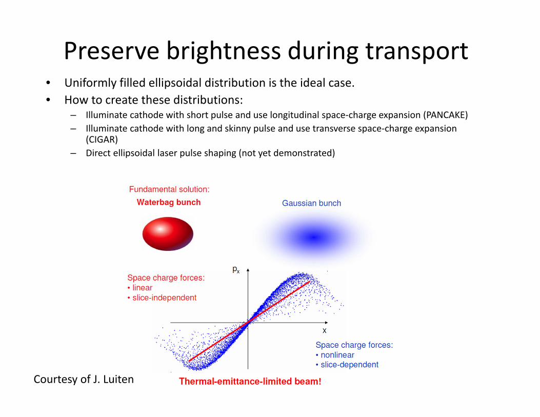
Preserve brightness during transport• Uniformly filled ellipsoidal distribution is the ideal case.• How to create these distributions:
– Illuminate cathode with short pulse and use longitudinal space‐charge expansion (PANCAKE)– Illuminate cathode with long and skinny pulse and use transverse space‐charge expansion
(CIGAR)– Direct ellipsoidal laser pulse shaping (not yet demonstrated)
Courtesy of J. Luiten

Charge 20 pC. Laser spot size 400 m rms (limited by asymmetry due to image charge)
rms length ~300 fs
Very sharp ellipsoidal beam boundary due to the ultrashort beam on the cathode.
When charge exceeds 10% strong asymmetry develops.
Ellipsoidal beam experimental demonstrationAt Pegasus
Deflector off
Deflector on
P. Musumeci, J. T. Moody, R. J. England, J. B. Rosenzweig, and T. Tran, Phys. Rev. Lett. 100, 244801 (2008)

Longitudinal phase space• Use vertically deflecting cavity in conjunction with horizontally dispersing
dipole• Record resolution in time (50 fs) and energy (1 keV).
• Advantages of measurement on low energy beams. • Can compress !
Very linear phase space
High 6D beam brightness
Ultralow longitudinal emittance (<0.5 um)

Cigar beams• “Blow‐out” or “pancake” regime requires large initial laser spot by definition.• Large cathode (thermal) emittance contribution• Alternative :
– Focus laser to tight transverse spot on cathode.– Stretch laser pulse and use long parabolic temporal profile.– Transverse space charge expansion creates ellipsoidal beam (again!) preserving emittance
(transverse counterpart of blow‐out).
10
20
35
25 50 75 100 125 150 175 2000123456789
1020 40 60 80 100 120 140 160
Thermal emittance (nm)
RMS spot size (um)
Cha
rge
(pC
)
Virtu
al c
atho
de fo
rmat
ion
nm emittance beam
40 MV/m
Blow-out

Ultralow charge nm‐emittance beams. Electron sources in low charge regime. 0.1 pC – 1 pC.
UED FELs laser‐based Advanced Accelerators
Normalized transverse emittance below 20 nm (comparable with TEMs)
Short pulse Long pulse
TEM grid‐based emittance measurement

Space charge limits in the emission
• PancakeMaximum surface charge density set by the cathode extraction field.
• CigarOnly charge within a radius distance from the cathode contributes to space charge field
D. Filippetto, P. Musumeci, M. Zolotorev, G. Stupakov, to appear in PRSTAB
2 cases:R > ze pancake aspect ratioR < ze cigar aspect ratio
2 0 0Q
2 ∝ 2
2 ∝ 0
Dowell, USPAS lecture

MeV UED science• Few published studies with time‐resolved data• Each one points to a specific MeV advantage
Single shot Thickness of sample < 100 fs temporal resolution
P. Musumeci et al. Applied Physics Letters, 063502 (2010)
S. Daraszewicz et al. Phys Rev B 184101 (2013)
P. Zhu et al. Appl. Phys. Lett. 103, 071914 (2013)

Beam compression Phase space manipulation to increase 5D brightness.
Pay a price in correlated energy spread Hard to apply to microscopy
Suggested first and demonstrated for DC gun. Van Oudheusden Phys. Rev. Lett. 105, 264801 (2010)
Workhorse for many RF compressed DC gun setups ! Concept can be applied to MeV beam as well
Pegasus beamlineRF gun
solenoidUED chamber
LinacDipole
Solenoid
Laser‐electron interaction chamber
Quads
Deflector
LPSdipole

RF linac compression• High shunt impedance linac• Independent RF feed
– Adjust phase and amplitude
• Beam too short for RF deflection resolution (?)
• CTR diagnostics (Xianhai Lu visiting student from Tsinghua University)

RF compression results• Maximize CTR signal with linac phase• Strong dependence on transverse spot size• Use filters at 1 THz and 5 THz to reconstruct spectral
content• Huge fluctuations due to RF – laser jitter !
Data analysis in progress
Due to fluctuations it is expected that the 1 THz detector should see near constant energy. 5 THz detector more sensitive.Take peak ratio of the two detectors and extract bunch length ~ 30 fs !

New hybrid gun compression• The idea: combine in a single structure beam
generation and beam compression.• Traveling wave section acts as a buncher• Beam tests at UCLA Pegasus Laboratory
(A.Fukasawa)• Bunch length measurements with 9.6 GHz
deflecting cavity• Obtained 1 pC ‐ 100 fs resolution limited• Scaling to X‐band gun (UCLA/SLAC/INFN
collaboration) yields sub‐10 fs beams in simulations.
11.5 MW
10.5 MW
9.5 MW
Measurement

Beyond time jitter‐limited resolution
• Time stamp using laser triggered streak camera kick on the main beam after diffraction
– Low charge– < 50 fs resolution (high voltage photoswitch stability)
• Electro‐Optic Sampling based time stamping before sample
– Down to 1 pC– MeV beams
C. M. Scoby, P. Musumeci et al., PRSTAB 13, 022801 (2010)
Timing jitter is at this point the main limitation in temporal resolution of electron scattering instruments.

New concepts for time stamping• Electron beam controlled transmission through
semiconductor membrane– Done with X‐ray demonstrated < 5 fs accuracy– Routinely used in laser accelerators (Ge and Co2)– Challenge to create enough electron‐hole pairs
• THz streaking– Also used at LCLS– THz with laser (optical rectification). Generates MV/m THz
field.– Use IFEL interaction with TEM01 mode to angular streak or
with TEM00 mode to energy streak– 10 fs resolution– Can use THz to compress too….
M. Harmand, Nature Photonics, 2013
From UCLA BNL IFEL experiment
0 1 2 3 4 50.000
0.003
0.006
0.009
Pow
er S
pect
ral D
ensi
ty (a
rb)
Frequency (THz)
100K Power Spectral Density 300K Power Spectral Density

Liquid cells• Take advantage of larger penetration of MeV beams• Collaboration with UCLA C. Regan’s group • Assembled from Si3N4 75 nm thick windows• Cell thickness set using 4.5 um polystyrene beads as
spacers (EMFP@ 3 MeV 1.5 um)• Illuminated with beam. Imaging and diffraction pattern
(ring from Si3N4)• Open the door to time‐resolved liquid phase experiments !• Post mortem after 4 hrs (1011 e‐ total dose) shows gas
bubbles: pulsed radiolysis?
Not irradiated After e‐beam Electron image
Single shot Diffraction pattern
Optical microscope

UCLA concept for MeV‐ps microscopy• Limit to incoherent imaging, 10 ps
temporal resolution and 10 nm spatial resolution.
– Dislocation and shock dynamics studies
• A simple path would be to modify an existing MeV microscope….
• Based on cigar aspect ratio regime• Condenser stage: energy spread silencing• Objective lenses: permanent magnet
quadrupoles
Parameters Values
Gun gradient 120 MV/m
Initial beam charge 1 pC
Laser spot‐size 40 um rms
Laser pulse length 10 ps
Normalized emittance 10 nm
Kinetic beam energy 5.00 MeV
Relative energy spread 5e‐6 rms
Sample plane
Energy spread Silencer
Objective lens
Projector Stages (1 or 2)
Objective Aperture
Detector plane
1.4 cell gun
GunSolenoid
Laser system
2nd condenser (optional)
Condenser Aperture
Photocathode driver
Pump arm
MeV electron beam

Energy spread silencing • Radiofrequency accelerating field not constant in time• 10 ps (10 deg @S‐band) long pulse shows large curvature in
longitudinal phase space and large energy spread• Use 3rd harmonic cavity to compensate and cancel 2nd order
curvature
• Partial compensation of slice energy spread too… • Final rms energy spread < 10‐5 or in absolute terms < 20 eV !
0cos
0 cos 3cos 3 with 3 0/9

Conical illumination MeV TEM• Collaboration with J. Spence & C. Koch• Reciprocity theorem• Equivalent to HAADF‐STEM• Could obtain atomic resolution with large angle
illumination (incoherent illumination)• BUT need extremely large flux (2 orders of magnitude
larger than current state‐of‐the‐art)
GPT simulations
STEM Image simulation: 30 nm thick SrTiO3Detector collects scattering angles from 10 .. 60 mradProbe convergence semi‐angle: 4.3 mrad
STEM
TEM
Acknowledgements
• Pegasus Laboratory: R. Li, H. To, E. Curry, K. Roberts, L. Ho, E. Threlkeld, J. Moody, X. Lu
• UCLA: A. Fukasawa, J. Rosenzweig, B. Spataro, S. Tochitsky, C. Regan, E. White
• External collaborators: L. Faillace, S. Boucher, F. Carbone, J. Luiten, X. J. Wang, D. Xiang, D. Filippetto, W. Wan, B. Reed

Conclusions• Better beam brightness key to all electron scattering
research• Phase space shaping might help specific applications (UED,
UEM). Pancake, Cigar and Beam Compression.• Relativistic electrons from RF photoinjectors competitive
with other approaches. Lots of room for improvements– Lower thermal emittance cathode research– High field RF cavity design
• MeV UED taking advantage of its unique characteristics.– Liquid phases– sub‐50 fs time‐resolution.
• Future goal within reach: MeV UEM with 10 nm‐10 psresolution