high-energy astrophysics and gas-filled ionization detectors · overview of ionization detectors...
TRANSCRIPT

High-Energy Astrophysics and Gas-Filled Ionization Detectors
Scott Griffiths
High-Energy Astrophysics
• High-energy astrophysical phenomena emit x-rays • X-rays are less susceptible to scattering from
interstellar dust • X-rays are often emitted from ultraluminous sources,
which allows observation of distant objects • X-ray data can be combined with optical, IR, and radio
band data • Typical x-ray emitting astrophysical objects:
– Black holes and AGNs – Neutron Stars – Supernovae and SNRs – Gamma Ray Bursts (GRBs)
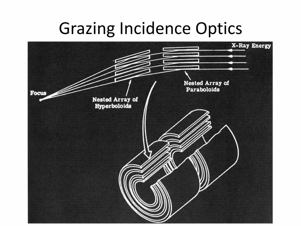
Grazing Incidence Optics
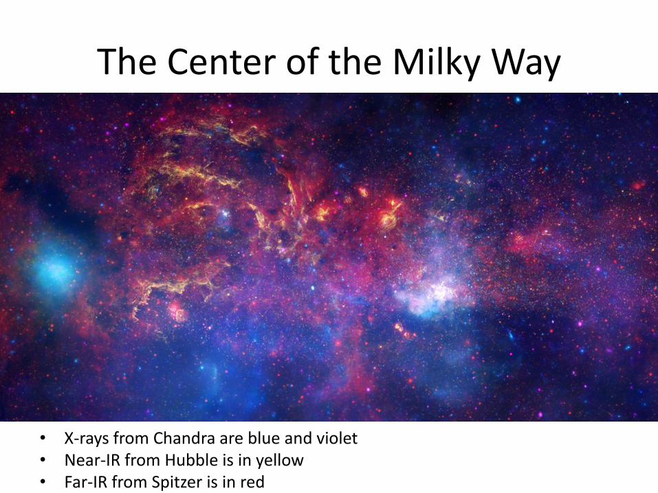
The Center of the Milky Way
• X-rays from Chandra are blue and violet • Near-IR from Hubble is in yellow • Far-IR from Spitzer is in red
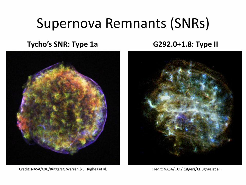
Supernova Remnants (SNRs) Tycho’s SNR: Type 1a G292.0+1.8: Type II
Credit: NASA/CXC/Rutgers/J.Hughes et al. Credit: NASA/CXC/Rutgers/J.Warren & J.Hughes et al.
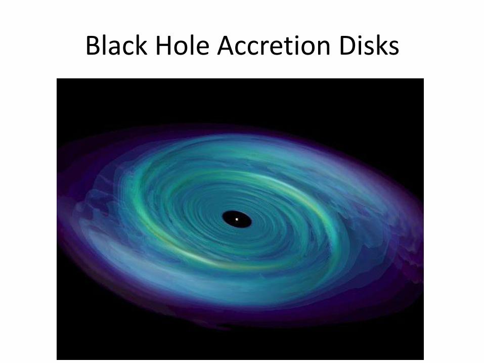
Black Hole Accretion Disks
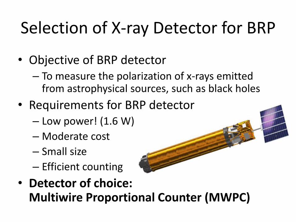
Selection of X-ray Detector for BRP
• Objective of BRP detector – To measure the polarization of x-rays emitted
from astrophysical sources, such as black holes
• Requirements for BRP detector – Low power! (1.6 W)
– Moderate cost
– Small size
– Efficient counting
• Detector of choice: Multiwire Proportional Counter (MWPC)
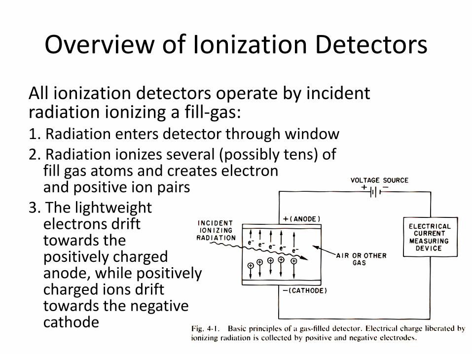
Overview of Ionization Detectors
All ionization detectors operate by incident radiation ionizing a fill-gas: 1. Radiation enters detector through window 2. Radiation ionizes several (possibly tens) of
fill gas atoms and creates electron and positive ion pairs
3. The lightweight electrons drift towards the positively charged anode, while positively charged ions drift towards the negative cathode
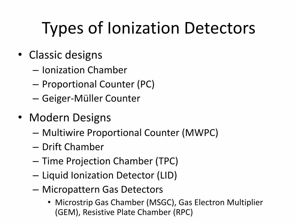
Types of Ionization Detectors
• Classic designs – Ionization Chamber
– Proportional Counter (PC)
– Geiger-Müller Counter
• Modern Designs – Multiwire Proportional Counter (MWPC)
– Drift Chamber
– Time Projection Chamber (TPC)
– Liquid Ionization Detector (LID)
– Micropattern Gas Detectors • Microstrip Gas Chamber (MSGC), Gas Electron Multiplier
(GEM), Resistive Plate Chamber (RPC)
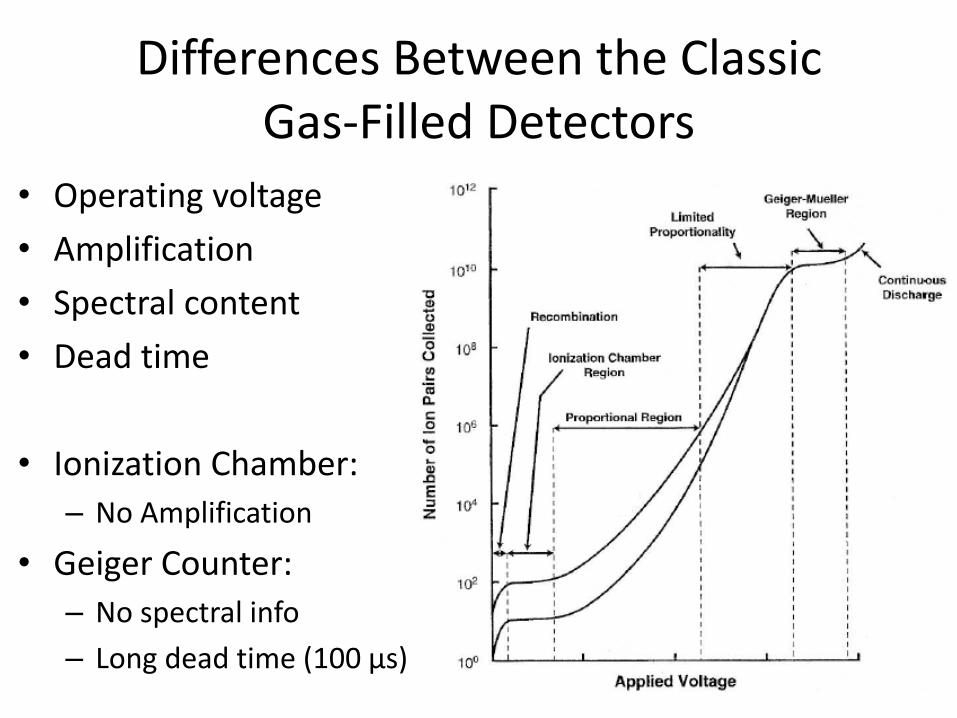
Differences Between the Classic Gas-Filled Detectors
• Operating voltage
• Amplification
• Spectral content
• Dead time
• Ionization Chamber:
– No Amplification
• Geiger Counter:
– No spectral info
– Long dead time (100 µs)
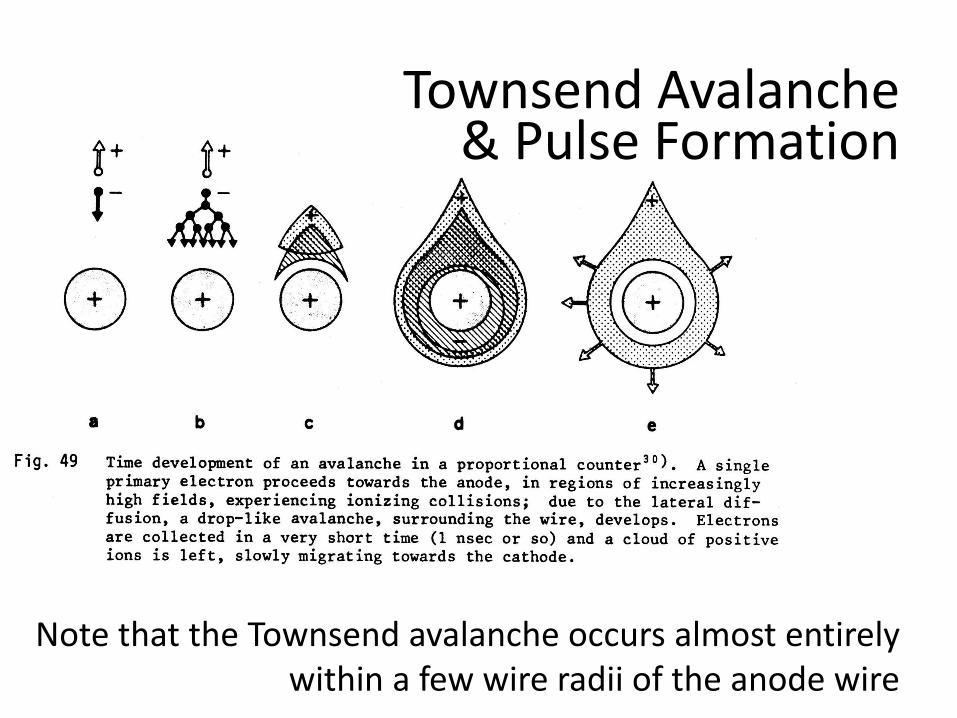
Townsend Avalanche & Pulse Formation
Note that the Townsend avalanche occurs almost entirely within a few wire radii of the anode wire
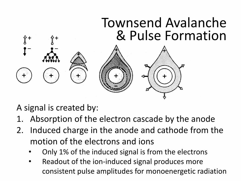
Townsend Avalanche & Pulse Formation
A signal is created by: 1. Absorption of the electron cascade by the anode 2. Induced charge in the anode and cathode from the
motion of the electrons and ions • Only 1% of the induced signal is from the electrons • Readout of the ion-induced signal produces more
consistent pulse amplitudes for monoenergetic radiation
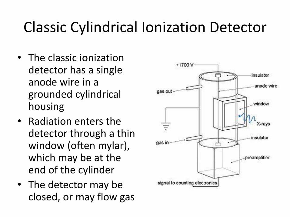
Classic Cylindrical Ionization Detector
• The classic ionization detector has a single anode wire in a grounded cylindrical housing
• Radiation enters the detector through a thin window (often mylar), which may be at the end of the cylinder
• The detector may be closed, or may flow gas
Fill Gas Interactions
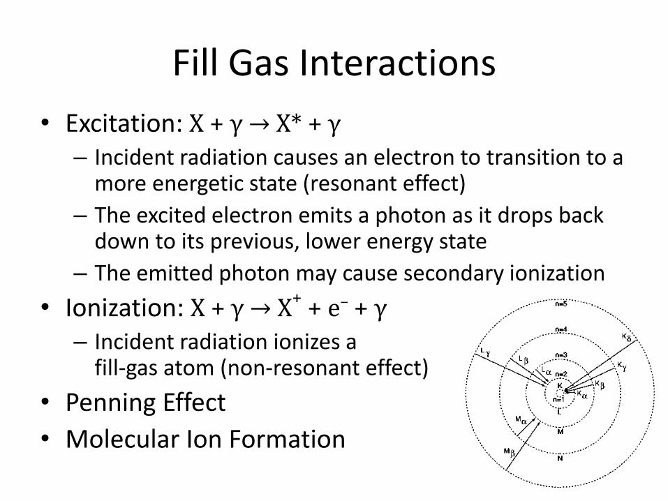
• Excitation: X + γ → X* + γ
– Incident radiation causes an electron to transition to a more energetic state (resonant effect)
– The excited electron emits a photon as it drops back down to its previous, lower energy state
– The emitted photon may cause secondary ionization
• Ionization: X + γ → X+ + e– + γ
– Incident radiation ionizes a fill-gas atom (non-resonant effect)
• Penning Effect
• Molecular Ion Formation
Fill Gas Selection Considerations
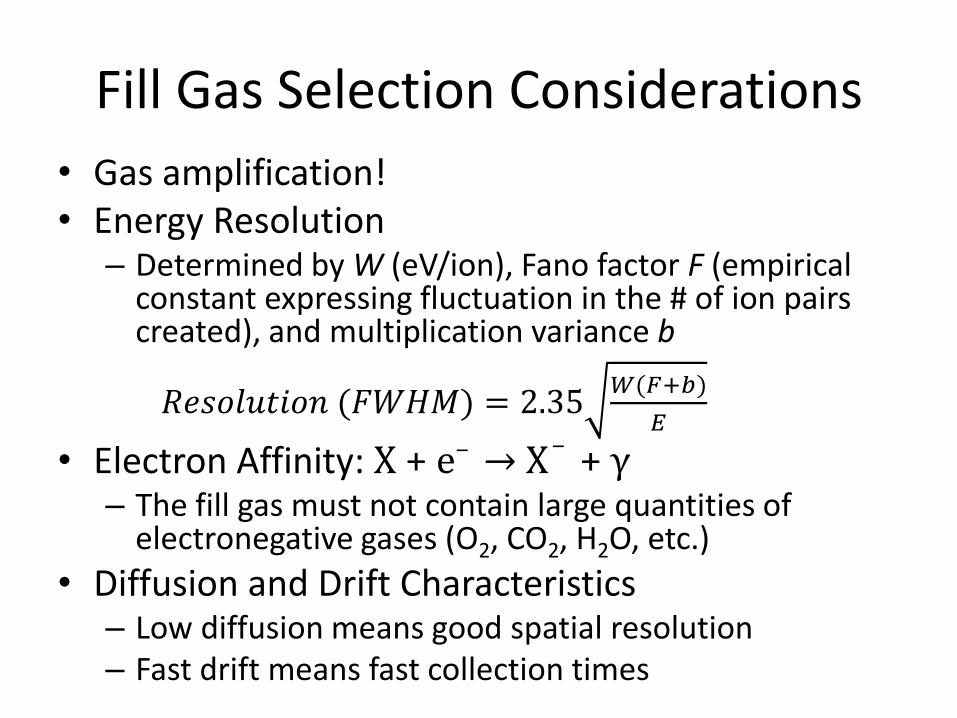
• Gas amplification! • Energy Resolution
– Determined by W (eV/ion), Fano factor F (empirical constant expressing fluctuation in the # of ion pairs created), and multiplication variance b
𝑅𝑒𝑠𝑜𝑙𝑢𝑡𝑖𝑜𝑛 (𝐹𝑊𝐻𝑀) = 2.35𝑊(𝐹+𝑏)
𝐸
• Electron Affinity: X + e– → X
– + γ – The fill gas must not contain large quantities of
electronegative gases (O2, CO2, H2O, etc.)
• Diffusion and Drift Characteristics – Low diffusion means good spatial resolution – Fast drift means fast collection times

Fill Gas Selection Considerations
• Quench Gas – A small amount of (typically) organic quench gas can
be used to preferentially absorb photons emitted from excitation and dissipate this energy in non-ionizing modes
– Prevents continuous discharge and allows for higher gas gains (~106 instead of ~104)
• Build-up Prevention Gas – Removes build-up from spent organic quench gas,
which can cause continuous discharge
• Environmental Impact (No Freon!) • Cost ($$$)
Continued
Multiwire Proportional Counters
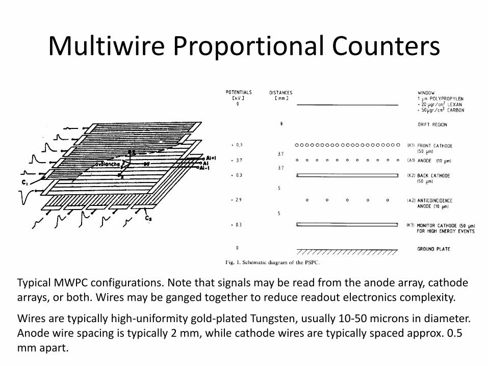
Typical MWPC configurations. Note that signals may be read from the anode array, cathode arrays, or both. Wires may be ganged together to reduce readout electronics complexity.
Wires are typically high-uniformity gold-plated Tungsten, usually 10-50 microns in diameter. Anode wire spacing is typically 2 mm, while cathode wires are typically spaced approx. 0.5 mm apart.

Field Geometry, Anodes Only
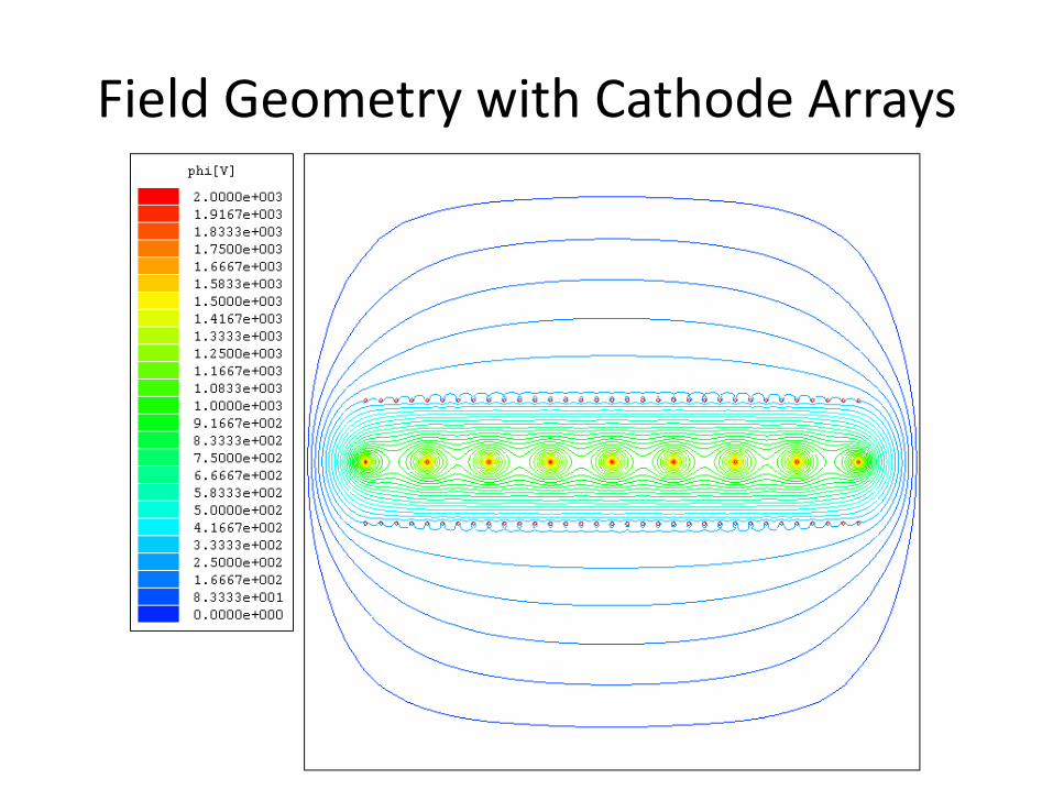
Field Geometry with Cathode Arrays
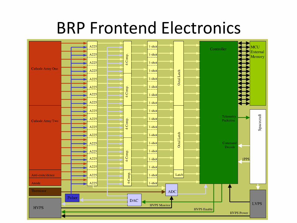
BRP Frontend Electronics
BRP Fill Gas Selection
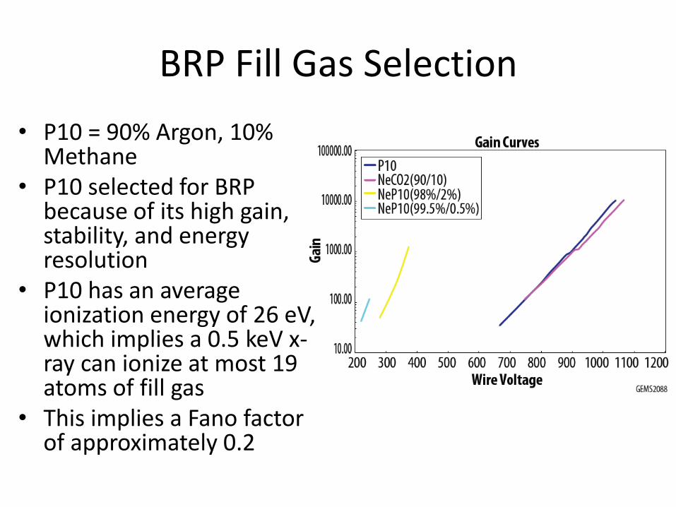
• P10 = 90% Argon, 10% Methane
• P10 selected for BRP because of its high gain, stability, and energy resolution
• P10 has an average ionization energy of 26 eV, which implies a 0.5 keV x-ray can ionize at most 19 atoms of fill gas
• This implies a Fano factor of approximately 0.2
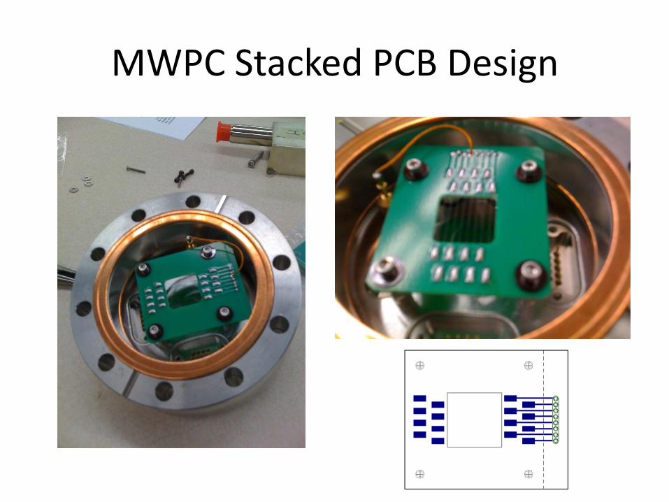
MWPC Stacked PCB Design
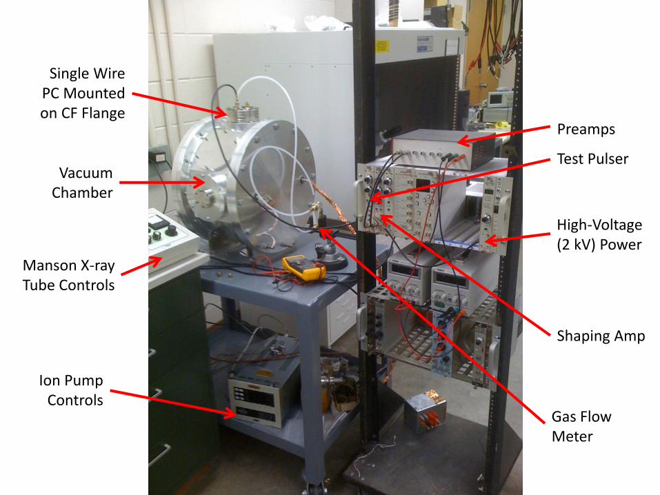
Preamps
Shaping Amp
Test Pulser
High-Voltage (2 kV) Power
Ion Pump Controls
Manson X-ray Tube Controls
Vacuum Chamber
Gas Flow Meter
Single Wire PC Mounted on CF Flange
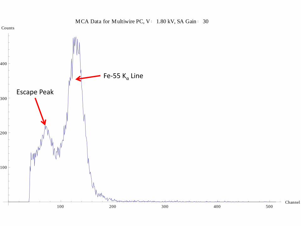
100 200 300 400 500Channel
100
200
300
400
Counts
MCA Data for Multiwire PC, V 1.80 kV, SA Gain 30
Escape Peak
Fe-55 Kα Line
10
100
1000
10000
100000
1000000
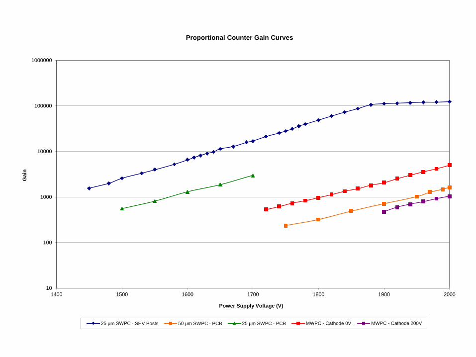
1400 1500 1600 1700 1800 1900 2000
Gain
Power Supply Voltage (V)
Proportional Counter Gain Curves
25 μm SWPC - SHV Posts 50 μm SWPC - PCB 25 μm SWPC - PCB MWPC - Cathode 0V MWPC - Cathode 200V
Primary References: