high energy lithium batteries for phev applications
TRANSCRIPT

High Energy Lithium Batteries for PHEV Applications
Subramanian Venkatachalam Envia Systems
Project ID: ES211
This presentation does not contain any proprietary, confidential, or otherwise restricted information
DOE Vehicle Technologies Program Annual Merit Review Washington D.C. June 16–20, 2014
Program Overview
2
Time line Start Date: Oct. 2013 End Date: Sept. 2015 Status: 25% Completed Budget Total Project Funding $3.79 M DOE: 80% Cost Share: 20%
Barriers • Meeting PHEV power specifications • Loss of power with cycling • Cycle and Calendar life Partners
• Lawrence Berkeley National Laboratory (LBNL)
• General Motors (GM)
• Oak Ridge National Laboratory (ORNL)
Project Lead – Envia Systems

Goals Develop a high capacity cathode, Si-C based anode and integrate them and build high capacity (0.25-40Ah) pouch cells that exceed the ABR minimum target goals for PHEVs
Project Tasks • Material development • Nanocoating engineering • Atomistic and cell-level modeling • Material scale-up • Large cell development • Large cell testing
3
Project Objectives - Relevance
Relevance • High DC-Resistance from HCMRTM Li-rich
cathodes reduce the power and usable energy of the cell
• Growth in DC-Resistance with cycling reduce the life of the cell
Cell Targets

HCMRTM Cathode Layered-Layered Structure
Li2MnO3
LiMO2 (M = Ni, Co, Mn)
x Li2MnO3 (1-x) LiMO2
During the First Charge:
(1) LiMO2 Li1-xMO2 + xLi+ + xe- where M = Ni, Co oxidation occurs ~ 3.7 V
(2) Li2MnO3 MnO2 + 2Li+ + 2e- + 1/2O2 which is irreversible and is limited only to 1st charge
During the Discharge:
(3) Li1-xMO2 + xLi+ + xe- LiMO2
(4) Li++MnO2+e- LiMnO2 (Li insertion into MnO2)
(Typical of HCMRTM)
(Classical reaction)
4
Envia has developed HCMR™ (High Capacity Manganese Rich ) cathodes based on layered-layered composite structures
Key benefits: • High Capacity • Low Cost • High safety
Key issues: • High DC-Resistance • Voltage fade upon cycling • Poor durability
Envia has licensed Lithium-rich Layered-Layered Li2MnO3
. LiMO2 composite patents from Argonne National Laboratory

HCMRTM Cathode: Development Status HEV, PHEV & EVs have different battery requirements ranging from power characteristics to cycle life. Envia solves the problem at the materials level by tailoring the cathode for each application. Morphology:
• Particle size, shape, distribution, tap density & porosity Composition:
• Ni, Co, Mn ratio, & Li2MnO3 content • Dopants concentration
Nanocoating: • Chemistry: fluorine, oxide, etc. • Thickness & uniformity
HCMRTM
Type C/10 Capacity Range mAh/g (4.6V-2.0V)
Status
XP 200 ~ 220 Commercialization
XE 225 ~ 240 R & D
XLE 240 ~ 280 R&D
5
In the ABR program, Envia is currently using HCMRTM – XLE cathode
Detailed cathode specifications are shared with the partners

PHEV Cell with HCMRTM XP Cathode 107 Wh, 27 Ah Cell 180 Wh/Kg at 1C
with graphite anode
0
5
10
15
20
25
30
0 1000 2000 3000 4000 5000
Cell
Capa
city
(Ah)
Cycles
1C charge & 2C discharge cycling (90% DOD)
75% retention (5000 cycles)
1
1.5
2
2.5
3
0.7
0.75
0.8
0.85
0.9
0.95
1
1.05
0 200 400 600
R/Ro
(@80
% S
OC)
Disc
harg
e Ca
paci
ty/I
nitia
l Ca
paci
ty
Number of Days
27Ah cells stored at 80% SOC and 45oC. Capacity measured @1C rate every 30 days
6
HCMR™ XP cells show no Voltage Fade
100% DOD: 4.35 ~ 2.2 V

HCMRTM XLE Cathode – Electrochemical Chemical Performance
160170180190200210220230240250
0 20 40 60
Spec
ific
Capa
city
[mAh
/g]
Cycle Number
80
85
90
95
100
11 21 31 41 51
Nor
mal
ized
Vol
tage
[%]
Cycle Number
XLE-1 Pristine
XLE-2 Nanocoated
C/10
C/5
C/3
1C
2C
C/3
Cycling at C/3 rate
• Baseline HCMRTM cathodes shipped to all program partners • Nano-coating increases specific capacity (~15mAh/g) showing good capacity
retention after 50 cycles at C/3 • Pristine material shows ~30mV higher voltage than the nanocoated material at the 1st
C/3 cycle, however, at the 50th cycles both materials show similar average voltage • Nanocoted cathode has lower voltage fade about 2.8% in a half cell. In a full cell the
average voltage stabilizes to 2-3% fade after 150 cycles
~15 mAh/g Average Voltage retention: XLE-2: 97.2 % retention XLE-1: 96.3 % retention
7
Tested in half cell 4.6V to 2.0V Tested in half cell 4.6V to 2.0V

DC-R Improvement by Carbon Coating
8
0
25
50
75
100
125
150
175
200
10 20 30 40 50 60 70 80 90
ASI [Ω
*cm
2]
ASI [%]
Cathode: 92% CAM Anode: 96% graphite Design: full-cell, pouch-cells Test: 4.4-2.0V
NCM [4.2-2.5V]
Baseline Material with Envia’s Nanocoating
XLE-2
Baseline Material with Envia’s Nanocoating
XLE-2 + Carbon Need to close DC-R Gap by doping, coating, morphology & composition engineering
DC-R improvement by Carbon coating

0
25
50
75
100
125
150
175
0 10 20 30 40 50 60 70 80 90 100
ASI [Ω
*cm
2]
SOC [%]
DC-R Impact on Usable Energy and Power
9
• HCMR™ XLE cathodes show a sharp increase in DC-R starting at 50% SOC which translates to a significant drop in power and lower usable energy
• On the contrary, HCMR™ XP cathodes show a flat DC-R profile from 90% to ~20% SOC translating to higher power and greater usable energy
HCMR™-XLE
Amount of Li2MnO3 in HCMRTM cathode materials determine the usable power and energy of the cell
0.00.20.40.60.81.01.21.41.61.82.0
0 10 20 30 40 50 60 70 80 90 100
Pow
er [W
] SOC [%]
An increase in DC-R translates to a significant loss of power
HCMR™- XP HCMR™-XLE
HCMR™- XP
Discharge DC-R test: 10 sec, 1C discharge pulse from single-layer pouch-cells

Li+
e-
DC-R– Models and Approaches for Improvement
10
Electronic conductivity
Charge transfer resistance
• Composition engineering of Li2MnO3
• Dopant engineering
• Reduction of particle size (morphology engineering)
• Reduction of O2 defects during formation
• Carbon coatings
• Dopant engineering
• Conducting polymer coatings
• LiPON nanocoating optimization (ionic)
• Nanocoating optimization (electronic)
Root cause Development Areas Team
Li+
e-
• Envia
• Envia/LBNL
• Envia
• LBNL/Envia
• Envia/GM
• Envia/LBNL
• LBNL
• ORNL
• LBNL/GM/Envia
Ionic conductivity

Project Development Roadmap
ALD (GM/Envia)
PVD (ORNL)
HCMRTM cathode (Envia) Coating development
Coated HCMRTM
Si-C anode (Envia)
Binder Development (LBNL)
High capacity cells to meet PHEV ABR cell targets
CELL INTEGRATION (Envia) & TESTING (All)
CATHODE DEVELOPMENT
Conductive binder + Si- based anode composite
ANODE DEVELOPMENT
PE-CVD (GM)
Mechano-Chemical (Envia)
Atomistic modeling & Synthesis (Envia, GM and LBNL)
Wet processing (Envia/LBNL)
GOAL: Develop a high capacity cathode and a Si-C based anode in order to build high capacity (0.25-40Ah) pouch cells that exceed the ABR target goals for PHEV applications.
11

12
LiPON • Stable to 5.5V • Stable against Li • Stable in liquid electrolyte • Grown by vapor deposition in N2 plasma
Nanocoating LiPON via Physical Vapor Deposition
0
1
2
3
4
5
0 5 10 15 20 25
P content from Lipon goes up with increasing deposition time
at%
P
Deposition Time (h)
Based ICP data
Increase in N content with deposition time
Source: ORNL
XPS
12
1. Secondary cathode particle aggregates appear to have similar morphology as uncoated or pristine cathode.
2. Shows nitrogen and phosphorus signal indicating homogenous coating 3. No attrition or degradation from grinding powders during deposition

96.096.597.097.598.098.599.099.5
100.0100.5
11 21 31 41 51
Nor
mal
ized
Volta
ge [%
]
Cycle Number
LiPON Coated HCMRTM Materials
160170180190200210220230240250
0 10 20 30 40 50 60
Spec
ific C
apac
ity [m
Ah/g
]
Cycle Number
XLE-1 Pristine
XLE-2 Nanocoated
XLE-1 Pristine
XLE-2 Nanocoated
XLE-1 LiPON – t1 deposition XLE-1 LiPON – t2 deposition XLE-1 LiPON – t3 deposition
XLE-1 LiPON – t1 deposition XLE-1 LiPON – t2 deposition XLE-1 LiPON – t3 deposition
~97%
• LiPON-coated cathodes show ~50mV higher average voltage than uncoated cathodes after 50 cycles at C/3
• LiPON-coated materials show ~5-10mAh/g higher capacity than uncoated cathodes • Voltage retention is improved from ~96% (uncoated) to ~97% (LiPON-coated) by LiPON
deposition, specially for low deposition times • Optimal LiPON thickness will be applied to the HCMR™-XLE2 to improve DC-R and high
voltage durability (cycle life and calendar life)
LiPON
Tested in half cell 4.6V to 2.0V
13

Nanocoating of HCMR™ Materials via ALD Process Objectives: (1) Explore different ALD nanocoatings - Al2O3, AlF3, AlN, ZnO, TiN etc. (2) Optimize the best ALD conditions to get uniform nanocoatings without compromising capacity (3) Investigate the effects of ALD-coated materials on the DC-R of HCMRTM cathode materials
AlF3 coatings with a thickness ~10nm are uniformly deposited on the surface of the HCMRTM particles
Source: GM 14

160170180190200210220230240250
0 10 20 30 40 50 60
Spec
ific C
apac
ity [m
Ah/g
]
Cycle Number
ALD Coated HCMRTM Materials
GM-1 ALD – Al2O3 GM-2 ALD – AlF3
XLE-1 Pristine
XLE-2 Nanocoated
C/10
C/5 C/3
1C
2C
C/3
96.096.597.097.598.098.599.099.5
100.0100.5
11 21 31 41 51
Nor
mal
ized
Volta
ge [%
]
Cycle Number
~97%
• ALD coated cathodes show capacities similar to pristine cathodes • ALD coated cathodes improve capacity retention, absolute average voltage and
average voltage retention (~1%) when compared to the pristine cathodes • Optimized ALD nanocoating will be applied to the HCMR™- XLE2 (Envia nanocoated)
to improve DC-R and high voltage durability (cycle life and calendar life)
GM-1 ALD – Al2O3 GM-2 ALD – AlF3
XLE-1 Pristine
C/3 cycling
Tested in half cell 4.6V to 2.0V
15

Material Challenges and Diagnostic Tools
Material Challenges • DC-R • DC-R growth with cycling • Capacity fade • Possible side reactions • Possible structural transformation
Full suite of tools
• EIS (Deeper insight in DC-R) • HPPC (Standard test of DC-R) • SEM/TEM (Morphology changes) • EDX (Elemental analysis) • XRD (Bulk structural changes) • FT-IR (Chemical bonding changes) • Raman (Chemical bonding changes) • Model system (Carbon and binder free)
0 50 100 150
-150
-100
-50
0
Z'
Z''
E4 HPPC RT 90% SOCE4 HPPC RT 80% SOCE4 HPPC RT 70% SOCE4 HPPC RT 60% SOCE4 HPPC RT 50% SOCE4 HPPC RT 40% SOCE4 HPPC RT 30% SOCE4 HPPC RT 20% SOC
10-2 10-1 100 101 102 103 104 105 106
-60
-30
0
Frequency (Hz)
Thet
a(°)
0 25 50
-25
0
Z'
Z''
Goal: Correlate electrochemical changes to their physical location in the cell to determine cause of these phenomena
Source: LBNL 16

Characterization Approach
• Pressing pure 100% cathode powder on Al foil • Ideal (Model) system • Testing in coin cell setup
• Cathode powder is laminated & calendared with additives (binder and carbons) into an Al current collector
• Testing in coin cell setup
Distribution Particle pressed into Al
Carbon and Binder Free Electrode Laminate Cathode Electrode
Advantages: •Approach reflects actual cell application •Testing matches DOE standards HPPC Testing
Advantages: •Signal is only from active cathode material •Easier for characterizing degradation
mechanisms
Surface laminate cathode
Source: LBNL 17

33.23.43.63.8
44.24.4
0% 50% 100%Volta
ge (V
) ver
sus
Li
State of Charge
HPPC – Laminate vs. Binder/Carbon Free Electrode Carbon and Binder Free Electrode Laminate Cathode Electrode
33.23.43.63.8
44.24.4
0% 50% 100%Vo
ltage
(V) v
ersu
s Li
State of Charge
• DC-R drops with cycling < 30% SOC • DC-R rises with cycling 30% to 90% SOC • Voltage Fade < 70% SOC
0
50
100
150
200
250
0% 50% 100%
Resi
stan
ce (Ω
/cm
2 )
Cycle 3
Cycle 8
Cycle 13
Cycle 33
0
20000
40000
60000
80000
0% 50% 100%
Resi
stan
ce (Ω
/cm
2 )
Cycle 3
Cycle 8
Cycle 13
Source: LBNL
18

0 10000 20000 30000
-30000
-20000
-10000
0
Z' (Ohm per square cm)
Z'' (
Ohm
per
squ
are
cm)
C20 HPPC RT Cycle 3C20 HPPC RT Cycle 8C20 HPPC RT Cycle 11
0 25 50 75
-75
-50
-25
0
Z' (Ohm per square cm)
Z'' (
Ohm
per
squ
are
cm)
E4 HPPC RT Cycle 3E4 HPPC RT Cycle 8E4 HPPC RT Cycle 13E4 HPPC RT Cycle 18E4 HPPC RT Cycle 23E4 HPPC RT Cycle 28E4 HPPC RT Cycle 33
Impedance for Insight into DC-R at 40% SOC Carbon and Binder Free Electrode
Laminate Cathode Electrode
• Cycling increases low frequency semicircle • DC-R growth because of slow time constant process (Slower than typical charge transfer process)
10-2 10-1 100 101 102 103 104 105 10610-1100101102103104105
Frequency (Hz)
|Z|
10-2 10-1 100 101 102 103 104 105 106100
101
102
Frequency (Hz)
|Z|
0 12 24 36
-12
0
Z' (Ohm per square cm)
Source: LBNL
19

Theoretical Modeling – DC-R and Phase Change Stable intermediate states as a function of SOC
(while keeping the layered structure) were predicted
At each stable intermediate state,
• Energy barrier calculation for Li hopping to a nearby site: Li ionic conductivity
• Density of states calculation to get the band gap: Electronic conductivity
Phase Transformation mechanism was revealed
• Mn-migration to the Li-layer, occurring at high charge (instantaneous at x<0.5, sluggish at 0.5<x<1 ), is a key factor resulting the phase transformation to spinel-like structures
How to prevent it? In BATT program, effect of doping on the voltage fade has been explored. In the ABR project we are looking at stabilizing the structure via doping to eliminate the DC-R growth with respect to cycling
• Partially dope for Li to decrease the tendency for Mn migration
• Partially dope for Mn and increase the Mn-migration barriers
Source: LBNL 20
Si-C Anode Development
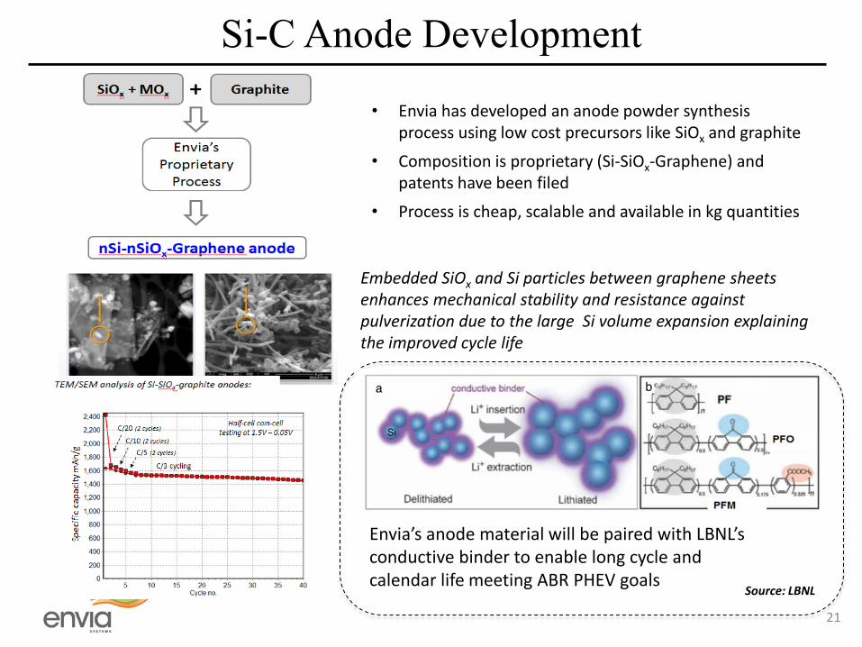
• Envia has developed an anode powder synthesis process using low cost precursors like SiOx and graphite
• Composition is proprietary (Si-SiOx-Graphene) and patents have been filed
• Process is cheap, scalable and available in kg quantities
Embedded SiOx and Si particles between graphene sheets enhances mechanical stability and resistance against pulverization due to the large Si volume expansion explaining the improved cycle life
Envia’s anode material will be paired with LBNL’s conductive binder to enable long cycle and calendar life meeting ABR PHEV goals
Source: LBNL
21

ABR Baseline Cell
930mAh capacity ABR baseline cells have been assembled and electrochemical performance (capacity & HPPC) is being tested and validated 12 ABR baseline cells were shipped to INL in April 2014 and testing protocols have been finalized DC-R measurements for the HCMR™/Si-C baseline cells show similar on-set as the Graphite cells Energy and power density evaluations, as well as, cycle life and calendar life are underway
22

Summary and Future Work Summary: • Conducting carbon coatings on cathode have reduced the DC-Resistance • LiPON coatings on cathode have improved average voltage without compromising specific
capacity • ALD coatings on cathode have improved capacity retention, absolute average voltage and
average voltage retention • Phase transition mechanisms have been revealed by Atomistic modeling suggesting Mn
migration to the Li layer Future Work: • Understand the root cause of DC-R and DC-R growth in HCMR™ cathodes using atomistic
modeling and diagnostic tools • Develop a cathode with low DC-R by optimizing the composition, dopants, nanocoating and
synthesis conditions • For LiPON coated HCMR™ materials (i) structural investigations using neutron diffraction &
aberration corrected electron microscopy and (ii) metal ion dissolution and oxygen loss will be studied
• Taylor unique conducting binders to improve the cycle life of Si-C based anodes • Optimize the integration of HCMRTM cathodes and Si-C anodes in a PHEV cell
23

Acknowledgements • Pedro Hernandez • Shabab Amiruddin • Bing Li • Charan Masarapu • Herman Lopez • Sujeet Kumar • Michael Sinkula • Jim Buckley • Envia Technical Team
• Bob Powell • Xingcheng Xiao • Mei Cai • K. Raghunathan
• Robert Kostecki • Vincent Battaglia • Guoying Chen • Gao Liu • Kristin Persson • Daniel Membreno • Lydia Terborg • Eunseok Lee • Alpesh K. Shukla
• Jagjit Nanda • Nancy Dudney • Gabrielle Veith
24

Technical Back up Slides

Baseline HCMR™-XLE Cathode Materials
Measurement Value Primary Particle (nm) 217±17 D50 (μm) 8.27 FWHM (μm) 8.11 BET (m2/g) 2.60 Tap Density (g/cc) 1.65 pH (Powder) 10.80 1st C/10 Charge (mAh/g) 284 1st C/10 Discharge (mAh/g) 238 Average Voltage at C/10 (V) 3.69
HCMRTM – XLE #1 (Uncoated) HCMRTM – XLE #2 (Envia Nanocoated)
26

27
HCMRTM-XLE cathode material shows Mn activity
upon repeated cycling
HCMR-XP cathode material showing no Mn activity with
cycling
Data from full cell: HCMR™-XP/XLE vs Graphite
2nd cycle 40th cycle 100th Cycle
Diffe
rent
ial C
apac
ity
dQ/dV plot comparing cycles 2,40,100
dQ/dV plot comparing cycles 2,40,100
HCMR™ XP vs. XLE - dQ/dV Analysis
