high explosive detection and destruction technology
TRANSCRIPT

!.
*
High Explosive Detection and Destruction Technology ApplicationsFor
Warhead Dismantlement Transparency
Dr. Rodion VoznyukFirst Deputy Director
Zababakhin Russian Federal Nuclear CenterSnezhinsk, Russia
M. Charles, A. Renlund, and R. RhoadesSandia National Laboratories
Albuquerque, New Mexico USA
ABSTRACT
This study identifies transparency measures and procedures that could be applied to the
process of High Explosive (HE) removal and destruction during warhead dismantlement. HighExplosive detection and destruction technologies were analyzed and demonstrated to a jointU.S./Russian Technical team. These included:● Gas analysis● Neutron-neutron. Neutron-gamma. Neutron activation. Hydro-j et cutting
Technical procedures and analysis of facility requirements for implementation were developed.An HE model assembly was also designed under this study to fully simulate all technicalparameters expected to be encountered during the actual dismantlement process. This model wasdesigned to meet the
● Required stability parameters of HE components● Adaptability to recycling technology. Physical-chemical, physical-mechanical properties
INTRODUCTION
With in the context of the Helsinki Summit Agreements, both the United States and theRussian Federation committed to “measures relating to the transparency of strategic nuclearwarhead inventories and the destruction of strategic nuclear warheads . . . . “. To help achieve abetter understand of those objectives within the Russian Federation, Sandia National Laboratoriesunder the auspices of the DOES Office of Arms Control and Non-Proliferation (NN-42) RussianLab to Lab Program, initiated a series of contracts with the Russian Nuclear Institutes to examinethe topic of Warhead Dismantlement and Transparency. The primary contributor to the High
Explosive detection and destruction analysis and technology development was the ZababakhinRussian Federal Nuclear Center of Technical Physics (VNHTF).
%rndia is a multiprogram laboratoryoperated by Sand& Corporation. aLockheed Martin Company. for theUnited Smw IIcpartnwn[ of Energyunder controct l) E-J\ C04-9-$AL850N.
DISCLAIMER
Portions of this document may be illegiblein electronic image products. Images areproduced from the best available originaldocument.
SNF/Ph4P 6.01.3(4/98, Rev. 1)
ASSIGNMENT PAGE
Summary of Preliminary Criticality Analysis forPeach Bottom Fuel in the
DOE Standardized Spent Nuclear Fuel Canister
DOCUMENT IDENTIFICATION NUMBER DoE/sNF/REP-041
DOCUMENT COPY NUMBER:
DOCUMENT HOLDER:NAME OR POSITION
DOCUMENT CONDITION STATEMENT
This document is subject to formal change control, audit,and recall; therefore, it should be carefidly maintained andkept readily available. The holder identified above isresponsible for maintaining this document in an up-to-datecondition by incorporating subsequent revisions as theybecome available. This document is the property of DOE-EM. On request, reassignment that ends the need for thedocument, or termination of employment with the DOE-EM, this document must be returned to the NSNFDocument Control Coordinator at the following address:
NSNF Document Control CoordinatorLockheed Martin Idaho Technologies Company
P. O. Box 1625Idaho Falls, ID 83415-3140
Phone: (208) 526-6837Fax: (208) 526-3730

DoE/sNF/REP-041Revision O
‘REGEIVEDUX 202000
fEN3TI
Summary of Preliminary Criticality Analysis forPeach Bottom Fuel in the
DOE Standardized Spent Nuclear Fuel Canister
Deborah J. Henrikson
Published January 1999
Idaho National Engineering and Environmental LaboratoryApplied Engineering and Development Laboratory
Lockheed Martin Idaho Technologies CompanyIdaho Falls, Idaho 83415
Prepared for theU.S. Department of Energy
Assistant Secretary for Environmental ManagementUnder DOE Idaho Operations Office
Contract DE-AC07-941D1 3223
DISCLAIMER
This report was prepared as an account of work, sponsored by an agency of theUnited States Government. Neither the United States Government nor any agencythereof, nor any of their employees, makes any warranty, express or implied, orassumes any legal liability or responsibility for the accuracy, completeness, orusefulness of any information, apparatus, product, or process disclosed, or representsthat its use would not infringe privately owned rights. References herein to anyspecific commercial product, process, or service by trade name, trademark,manufacturer, or otherwise, does not necessarily constitute or imply its endorsement,recommendation, or favoring by the United States Government or any agencythereof. The views and opinions of authors expressed herein do not necessarily stateor reflect those of the United States Government or any agency thereof.

. Summary of Preliminary Criticality Analysis forPeach Bottom Fuel in the
DOE Standardized Spent Nuclear Fuel Canister
Preparer: /.2$7.99Dt&orah J. Henrikson Date
Approvals
Independent Reviewer
PM/TL:
Manager, NSNF Support:
?
LL=-z4L,-\/ Leland’lvl . Mbhtierth
01d24JBQ%..
Doyle L. Batt~ o
-LktkLDate
NSNF Quality AssuranceProgram Manager (QAPM): )’?!)$AAA“
Robert D. Davis$4/?7
Date
NSNF Program Managec JJames H. Boyd U

Summary of Preliminary Criticality Analysis for Peach Bottom Fuel DOE/SNF/REP-041 Rev. O
Abstract
TheNational Spent Nuclear Fuel Program is developing a standardized set of canisters forDepartment of Energy (DOE) spent nuclear fuel (SNF). These canisters will be used for DOESNF handling, interim storage, transportation, and disposal in the national repository. Severalfuels are being examined in conjunction with the DOE SNF canisters.
This report summarizes the preliminary criticality safety analysis, that addresses general fissileloading limits for Peach Bottom graphite fuel in the DOE SNF canister. The canister isconsidered both alone and inside the 5-HLWIDOE Long Spent Fuel Co-disposal Waste Package,and in intact and degraded conditions.
Results are appropriate for a single DOE SNF canister. Specific facilities, equipment, canisterinternal structures, and scenarios for handling, storage, and transportation have not yet beendefined and are not evaluated in this analysis. Because these details are not yet available, resultstie not considered fully validated and are not suitable for establishing operational criticalitysafety controls. In addition, fmil DOE SNF canister or Waste Package design, operationalconsiderations, or facility configumtions could further restrict the canister loading. A completecriticality safety evaluation, including full validation and contingency and accident analyses,must be completed before Peach Bottom fuel is loaded into the DOE SNF canister.
The analysis assumes that the DOE SNF canister is designed so that it maintains reasonablegeometric integrity. Parameters important to the results are the canister outer diameter, innerdiameter, and wall thickness. These parameters are assumed to have nominal dimensions of45.7-cm (18.O-in.), 43.815-cm (17.25-in.), and 0.953-cm (0.375-in.), respectively.
Calculations assumed bare Peach Bottom fuel elements in the small-diameter, 456.9-cm-longDOE SNF canister. Assuming beginning-of-life 235Uand maximum end-of-life 233U,thecalculated results are: 15 intact elements in the DOE SNF canister, &ff+ 20 = 0.884; 15 elementsin degraded condition in the co-disposal waste package, ~ff + 20 = 0.977; 14 elements indegraded condition in the co-disposal waste package, &ff + 2G= 0.954. If 50 kg of iron in theform of geothite is added, ~ff + 20 = 0.883 for 15 elements in degraded condition in the co-disposal waste package.
Based on these results, the recommended fissile loading for the DOE SNF canister is 13 PeachBottom fuel elements if no internal steel is present, and 15 Peach Bottom fuel elements if creditis taken for internal steel.
Summary of Preliminary Criticality Analysis for Peach Bottom Fuel DOE/SNF/REP-041 Rev. O
m ii
This page intentionally blank.
Summary of Preliminary Criticality Analysis for Peach Bottom Fuel DOE/SNF/REP-041 Rev. O...
p. Ill
Terms and Acronyms
ANs
ANSI
BOL
DOE
ENDF/B-V
EOL
HLw
IFSF
hff
MCNP
OD
QARD
RW
SNF
Ss
A
G
American Nuclear Society
American National Standards Institute
beginning-of-life (pre-irradiation)
United States Department of Energy
evaluated nuclear data fde/version B-V
end-of-life (post-irradiation)
High Level Waste
Irradiated Fuel Storage Facility
effective neutron multiplication factor
Monte Carlo N-Particle Transport Code Systemm
outer diameter
Quality Assurance Requirements and Description, DOE/RW-0333P
OCRWM, DOE OffIce of Civilian Radioactive Waste Management
Spent Nuclear Fuel
stainless steel
delta, difference
standard deviation
Summary of Preliminary Criticality Analysis for Peach Bottom Fuel DOE/SNF/REP-041 Rev. O
D. iv
This page intentionally blank.
Summary of Preliminary Criticality Analysis for Peach Bottom Fuel DOE/SNF/REP-041 Rev. O
p. v
Table of Contents
Abstract .................................+............................................................................................ i
Terms and Acronyms...
....................................................................................................... Ill
Table of Contents .............................................................................................................. v
List of Tables ................................................................................................................... vii
List of Figures ................................................................................................................. vii
1.0
2.0
3.0
4.0
5.0
6.0
7.0
8.0
9.0
Introduction ........................................................................................................... 1
Description
2.1 Peach Bottom Fuel .................................................................................... 1
2.2 DOE Standardized SNF Canister .............................................................. 5
2.3 5-HLW/DOE Long Spent Fuel Co-disposal Waste Package .................... 5
Requirements Documentation ............................................................................... 6
Methodology
4.1 Calculational Codes and Cross Sections ................................................... 7
4.2 Validation .................................................................................................. 7
Discussion of Contingencies ................................................................................. 7
Evaluation &Results
6.1 Description of Model ................................................................................. 8
6.2 Calculations ............................................................................................... 9
Design Features and Administratively Controlled Limits & Requirements ....... 14
Summary & Conclusions .................................................................................... 14
References ........................................................................................................... 15
—

This page intentionally blank.
Summary of Preliminary Criticality Analysis for Peach Bottom Fuel DOE7SNF/REP-041 Rev. O
p. vi
Summary of Preliminary Criticality Analysis for Peach Bottom Fuel DOE/SNF/REP-041 Rev. O
m vii
Table 1.
Table 2.
Table 3.
Table 4.
Table 5.
Table 6.
Table 7.
Table 8.
Table 9.
Table 10.
Figure 1.
Figure 2.
List of Tables
Peach Bottom Fuel Elements: Beginning-of-Life Loadings (grams) .................4
Peach Bottom Fuel Element End-of-Life Loadings ........................................... 4
Peach Bottom End-of-Life Total Core Loadings ............................................... 5
Fuel Annulus Compositions ............................................................................... 8
Core 1 Type 3 Poison Rod Composition ............................................................ 9
Calculational results for canister design ........................................”...................... 9
Calculated results from 19-element spacing study ............................................ 10
Calculated resukfor triangular-pitched arrays ............................................... 11
Calculated results for degraded Iiel region ...................................................... 12
Calculated results for composition comparison ............................................. 13
List of Figures
Peach Bottom Standard Fuel Element .............................................................. 3
Several element configurations used for calculations ..................................... 10
Summary of Preliminary Criticality Analysis for Peach Bottom Fuel DOE/SNF/REP-041 Rev. O...
D. VIII
This page intentionally blank.
Summary of Preliminary Criticality Analysis for Peach Bottom Fuel DOE/SNF/REP-041 Rev. Op. 1 of 16
1.0 Introduction
The National Spent Nuclear Fuel Program is developing a standardized set of canisters forDepartment of Energy (DOE) spent nuclear fuel (SNF). These canisters will be used for DOESNF handling, interim storage, transportation, and disposal in the national repository. Severalfuels are being examined in conjunction with the DOE SNF canisters.
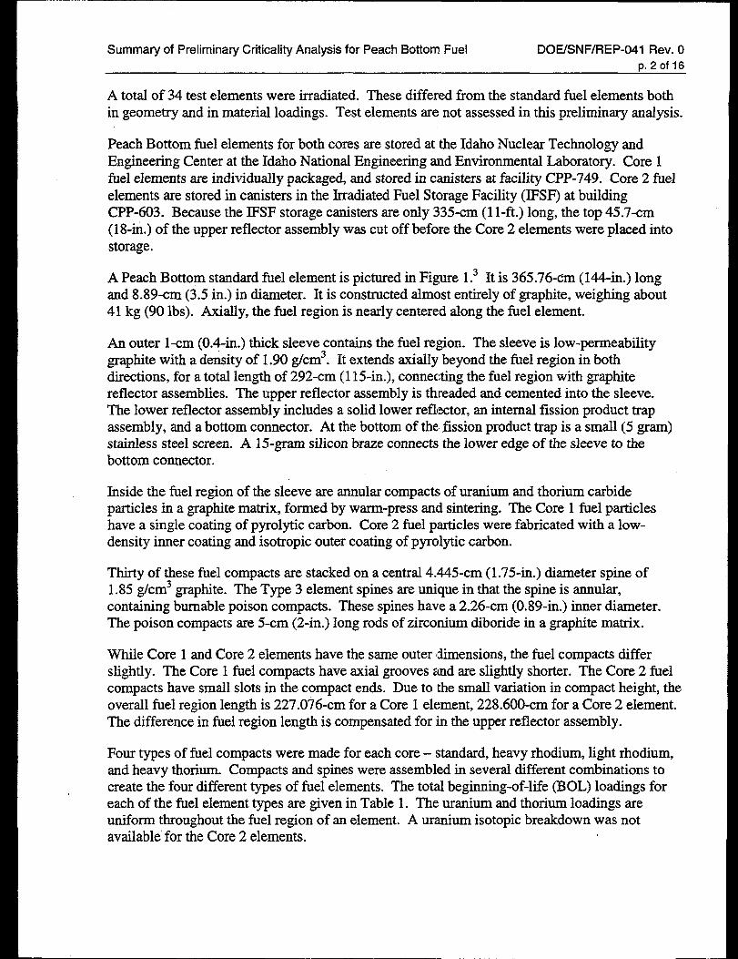
This report summarizes results from a detailed preliminary criticality safety analysisl thataddresses general fissile loading limits for Peach Bottom graphite fuel in the DOE SNF canister.The Peaeh Bottom fuel elements are considered in both intact and degraded conditions. Thecanister is considered both alone and inside the 5-HLWIDOE Long Spent Fuel Co-disposalWaste Package.
All data pertaining to the Peach Bottom fuel element geometry and material loadings is accuratebut considered unqualified. These data were not acquired, developed, or qualified in accordancewith an approved quality assurance program that meets DOE/RW-0333P (QARD).2 Resultspresented were determined using a qualified code per the QARD, but are not considered fullyvalidated.
Results are appropriate for a single DOE SNF canister. Specific facilities, equipment, canisterinternal structures, and scenarios for handling, storage, and transportation have not yet beendefined and are not evaluated in this analysis. Because these details are not yet available, resultsare not suitable for establishing operational criticality safety controls. In addition, final DOESNF canister or Waste Package design, operational considerations, or facility configurationscould further restrict the canister loading. A complete criticality safety evaluation, including fullvalidation and contingency and accident analyses, must be completed before Peach Bottom fuelis loaded into the DOE SNF canister.
2.0 Description
2.1 Peaeh Bottom Fuel Elements3
Peach Bottom Unit 1 was a prototype high-temperature gas-cooled reactor. It used graphitemoderation with highly enriched uranium-thorium carbide I%el. It operated from March 1966 toOctober 1974 using two fuel cores. Core 1 had a higher fissile loading and 450 days ofexposure. Core 2 had 900 days of exposure. Each core used four types of standard fielelements: I – heavy rhodium II – light rhodium; III – light rhodium with poison; and IV – heavythorium/light uranium. A nominal core loading contained 54 Type I elements, 564 Type II, 84Type III, and 102 Type IV.
Cores 1 and 2 eaeh had 36 instrumented fuel elements. These looked very much like thestandard fuel elements, with the exception of the bottom connector. The modified bottomconnector does not have a notched end like the standard bottom connector. All instrumentedelements had thermocouples; some were equipped with acoustic thermometers. Instrumented :fuel elements have the same fuel loadings as standard fiel elements and were used in place ofstandard fuel elements.
Summary of Preliminary Criticality Analysis for Peach Bottom Fuel DOE/SNF/REP-041 Rev. O
t).2of16
A total of 34 test elements were irradiated. These differed from the standard fuel eIements bothin geometry and in material loadings. Test elements are not assessed in this preliminary analysis.
Peach Bottom fuel elements for both cores are stored at the Idaho Nuclear Technology andEngineering Center at the Idaho National Engineering and Environmental Laboratory. Core 1fuel elements are individually packaged, and stored in canisters at facility CPP-749. Core 2 fuelelements are stored in canisters in the Irradiated Fuel Storage Facility (lI?SF) at buildingCPP-603. Because the IFSF storage canisters are only 335-cm (1 l-ft.) long, the top 45.7-cm(18-in.) of the upper reflector assembly was cut off before the Core 2 elements were placed intostorage.
A Peach Bottom standard fiel element is pictured in Figure 1.3 It is 365.76-cm (144-in.) longand 8.89-cm (3.5 in.) in diameter. It is constructed almost entirely of graphite, weighing about41 kg (90 lbs). Axially, the fiel region is nearly centered along the fbel element.
An outer l-cm (0.4-in.) thick sleeve contains the fuel region. The sleeve is low-permeabilitygraphite with a density of 1.90 g/cm3. It extends axially beyond the fieI region in bothdirections, for a total length of 292-cm (115-in.), connecting the fuel region with graphitereflector assemblies. The upper reflector assembly is threaded and cemented into the sleeve.The lower reflector assembly includes a solid lower reflector, an internal fission product trapassembly, and a bottom connector. At the bottom of the fission product trap is a small (5 gram)stainless steel screen. A 15-gram silicon braze connects the lower edge of the sleeve to thebottom connector.
Inside the fuel region of the sleeve are annular compacts of uranium and thorium carbideparticles in a graphite matrix, formed by warm-press and sintering. The Core 1 fuel particleshave a single coating of pyrolytic carbon. Core 2 fuel particles were fabricated with a low-density inner coating and isotropic outer coating of pyrolytic carbon.
Thirty of these fuel compacts are stacked on a central 4.445-cm (1.75-in.) diameter spine of1.85 g/cm3 graphite. The Type 3 element spines are unique in that the spine is annular,containing burnable poison compacts. These spines have a 2.26-cm (0.89 -in.) inner diameter.The poison compacts are 5-cm (2-in.) long rods of zirconium diboride in a graphite matrix.
While Core 1 and Core 2 elements have the same outer dimensions, the fuel compacts differslightly. The Core 1 fiel compacts have axial grooves and are slightly shorter. The Core 2 fuelcompacts have small slots in the compact ends. Due to the small variation in compact height, theoverall fuel region length is 227.076-cm for a Core 1 element, 228.600-cm for a Core 2 element.The difference in fiel region length is compensated for ~mthe upper reflector assembly.
Four types of fuel compacts were made for each core – standard, heavy rhodium, light rhodium,and heavy thorium. Compacts and spines were assembled in several different combinations tocreate the four different types of fuel elements. The total beginning-of-life (BOL) loadings foreach of the fuel element types are given in Table 1. The uranium and thorium loadings areuniform throughout the fuel region of an element. A uranium isotopic breakdown was notavailable’ for the Core 2 elements.

Summary of Preliminary Criticality Analysis for Peach Bottom Fuel DOE/SNF/REP-041 Rev. O~.3bf 16
—
86!
A A
‘an
core172.644cmcore2 71.120cm
v
Core1 227.076cmCore2 228.600cm
,
W34 cm
T-1 4
[
,/./..--’
...-———
!1
Figure 1. Peach Bottom Standard Fuel Element
/’/
/’/’
UPPERREFLECTORASSEMBLY
FUELCAP
SPINE
FUELCOMPACTASSEMBLY
SLEEVE
LOWERREFLECTOR
INTERNALTRAPASSEMBLY
SCREEN
SILICONBRAZE
BOITOMCONNECTOR
From Reference 3
Summary of Preliminary Criticality Analysis for Peach Bottom Fuel DOE/SNF/REP-041 Rev. OrJ.4.Of16
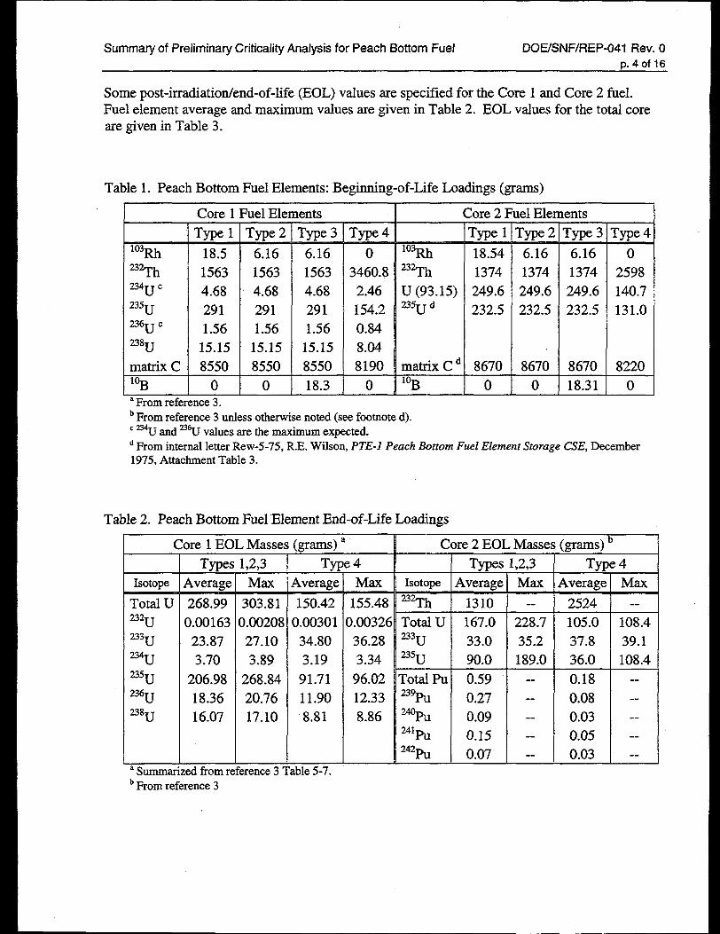
Some post-irradiation/end-of-Iife (EOL) values are specified for the Core I and Core 2 fbel.Fuel element average and maximum values are given in Table 2. EOL values for the total coreare given in Table 3.
Table 1. Peach Bottom Fuel Elements: Beginning-of-Life Loadings (grams)
Core 1 Fuel Elements i Core 2 Fuel Elements
Type 1
18.515634.68
2911.56
15.15
8550
0
Type 2
F15634.68
291
1.5615.15
8550
0
Type 3
%%_15634.68
2911.56
15.158550
18.3
Type 4 Type 1
18.541374249.6
232.5
rype 2
G1374249.6232.5
86700
Type 3
z1374
249.6
232.5
8670
18.31
rype 4
T2598
140.7
131.0
8220
0
103Rh‘~h234 cu235u236 Cu238u
matrix C
‘%
——103Rll
‘~hu (93.15)235 du
o
3460.82.46
154.20.848.048190 matrix C d
T—
8670
00‘From reference 3.bFrom reference 3 unless otherwise noted (see footnote d).c ‘U and % values are the maximum expected.dFrom internal letter Rew-5-75, R.E. Wilson, PTE-I PeachBottomFuelElementStorageCSE,December1975, Attachment Table 3.
Table 2. Peach Bottom Fuel Element End-of-Life Loadings
Core 1 EOL Masses (mans) a Core 2 EOL Masses (zrarns) b
T~
\verage
150.42
).00301
34.803.19
91.71
11.908.81
.ble5-7.
Type:
Averagt
x
1,2,3
Max
Types
Average
268.99
0.0016323.873.70
206.98
18.36
16.07
1,2,3 t4
Max
155.48
1.0032t36.283.34
96.0212.33
8.86
Typ
Average
2524
105.0
37.836.0
0.18
0.080.030.05
0.03
4
Max——
Isotope
23%
Isotope Max
Total U232u233u234u235U
236u238u
aSummm
303.81
3.0020827.10
3.89
268.8420.7617.10
-- --
Total U233u235u
167.0
33.090.0
228.7
35.2189.0
108.4
39.1108.4
Total Pu2%%
2%24%
242Pu
0.59
0.27
0.09
0.15
0.07
--
--
--
--
--
-.
-.
--
--
d from r( erence 3‘bFrom reference 3
Summary of Preliminary Criticality Analysis for Peach Bottom Fuel DOE/SNF/REP-041 Rev. OD.50f16
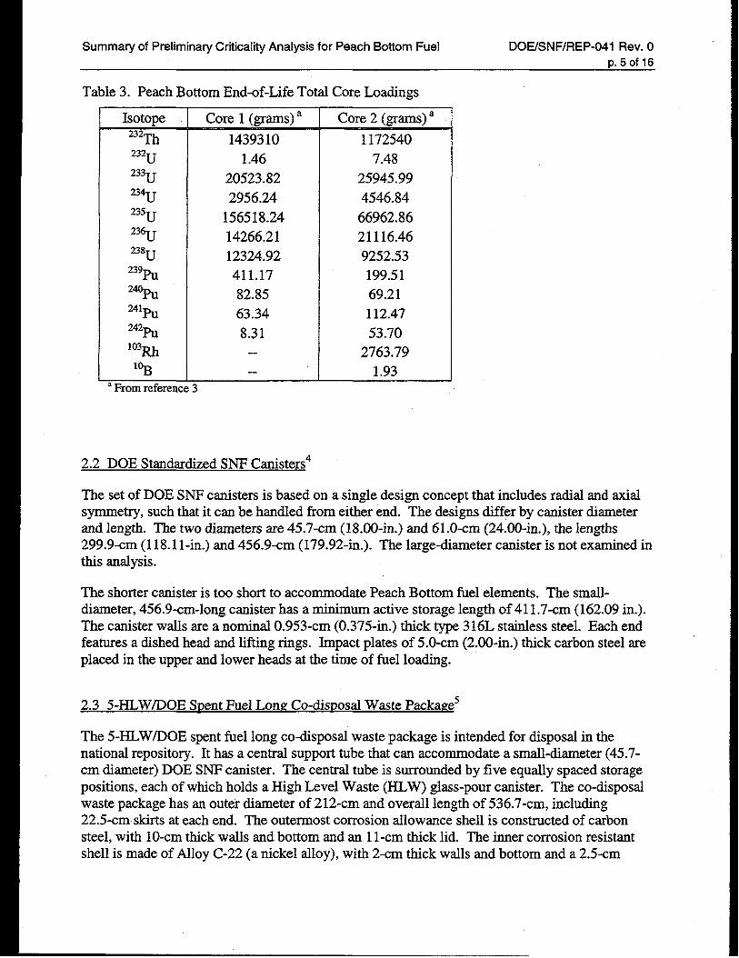
Table 3. Peach Bottom End-of-Life Total Core Loadings
Isotope
232Th232u233
23;235
‘3:238u
239PU
2%U
%%
242PU
103Rh
1%
Core 1 (grams) a
1439310
1.4620523.82
2956.24
156518.24
14266.2112324.92411.1782.8563.34
8.31.-
--
Core 2 (grams) a
1172540
7.48
25945.99
4546.84
66962.86
21116.46
9252.53199.5169.21112.47
53.702763.79
1.93aFrom reference 3
2.2 DOE Standardized SNF Canisters4
The set of DOE SNF canisters is based on a single design concept that includes radial and axialsymmetry, such that it can be handled from either end. The designs differ by canister diameterand length. The two diameters are 45.7-cm (18.00-in.) and 61.O-cm (24.00-in.), the lengths299.9-cm (118.1 l-in.) and 456.9-cm (179.92-in.). The large-diameter canister is not examined inthis analysis.
The shorter canister is too short to accommodate Peach Bottom fuel elements. The small-diameter, 456.9-cm-long canister has a minimum active storage length of 41 1.7-cm (162.09 in.).The canister walls are a nominal 0.953-cm (0.375-in.) thick type 316L stainless steel. Each endfeatures a dished head and lifting rings. Impact plates of 5.O-cm (2.00-in.) thick carbon steel areplaced in the upper and lower heads at the time of fuel loading.
2.3 5-HLWAOE Spent Fuel Long Co-disuosal Waste Packages
The 5-HLW/DOE spent fuel long co-disposal waste package is intended for disposal in thenational repository. It has a central support tube that can accommodate a small-diameter (45.7-cm diameter) DOE SNF canister. The central tube is surrounded by five equally spaced storagepositions, each of which holds a High Level Waste (HLW) glass-pour canister. The co-disposalwaste package has an outer diameterof212-cm and overall length of 536.7-cm, including22.5-cm skirts at each end. The outermost corrosion allowance shell is constructed of carbonsteel, with 10-cm thick walls and bottom and an 1l-cm thick lid. The inner corrosion resistantshell is made of Alloy C-22 (a nickel alloy), with 2-cm thick walls and bottom and a 2.5-cm
Summary of Preliminary Criticality Analysis for Peach Bottom Fuel DOE/SNF/REP-041 Rev. O
p.6of16
thick lid. A 3-cm closure lid gap separates the two lids. The inner cavity length is 461.7-cm.The central support tube is constructed of 3. 175-cm thick carbon steel. Web-like carbon steelplates connect the support tube to the inner shell and form the five external storage positions.Both the support tube and the plates are 459.7-cm long.
For this analysis, it is assumed that Hanford HLW Glass Pour canisters are in the externalstorage positions of the co-disposal waste package. These are representative of typical wasteglass canisters expeeted for the long co-disposal waste package. The canisters are constructed ofType 304L stainless steel with an outer diameter of 61-cm and length of 457.2-cm. The walltlikness is 1.05-cm.87% of the volume.
The total HLW canister weight is 4200 kg, with the waste glass occupying
3.0 Requirements Documentation
The Preliminary Design Specification for the DOE SNF canisters asserts that the SNF will beloaded into the canister such that criticality concerns during the canister’s design life will beprecluded. This can be achieved by proper fissile loading limits, by properly designed internals,or by a combination of both. The specification also states that for criticality concerns, the DOESNF canister must be capable of maintaining reasonable geometric integrity only.
This analysis is preliminary in nature. As such, standarci quality assurance criteria for a typicalcriticality safety evaluation do not specifically apply, but are invoked voluntarily whereappropriate. Criticality safety criteria are contained in national standards ANSI/ANS-8. 1,6-8.7,7and –8. 19,8standard DOE-STD-3007-93,9 and 10 CFR parts 60, 61,71, and 72. The analysis isrequired to be well documented, have a validated calculation method and verified software code,and to be independently reviewed. To be considered well documented, an analysis must bereported in sufficient detail to allow independent judgment and reproduction of results by aqualified criticality safety analyst. A documented criticality safety analysis is required todemonstrate fissile systems will be subcritical under normal and credible abnormal conditions.Some criteria require limits based on validated calculations not exceed a calculated km of 0.95.These standard quality assurance requirements are consistent and compatible with applicablecriteria of DOELRW-0333P, Quality Assurance Requirements and Description (QARD) for theOffice of Civilian Radioactive Waste Management (RW).2 The criticality safety analysissummarized in this report is well documented, was conducted with verified software code, andwas independently reviewed. The calculation method was validated only partially, but validationwas sufilcient to provide some confidence in results.
Summary of Preliminary Criticality Analysis for Peach Bottom Fuel DOE/SNF/REP-041 Rev. O
r).rof 16
4.0 Methodology
4.1 Calculational Codes and Cross Sections
The calculations for this evaluation were performed using MCNP 4B2, with the ENDF/B-Vcontinuous energy cross section library.l” Calculations were carried out on a networked systemof Hewlett-Packard 9000 series workstations under version 10.20 of the HPUX UNIX operatingsystem. MCNP is a generalized geometry Monte Carlo transport code qualified to comply withQARD requirements.*1 It is considered by the National Spent Nuclear Fuel Program to betransferred software.]2 The Iocal copy of this software and its accompanying data Iibraries aremaintained by RW-qualified personnel.
4.2 Validation
Complete validation for this analysis could not be accomplished because specific facilities,equipment, and scenarios for handling, storage, and transportation have not yet been defined.Several validation cases for the Peach Bottom fuel are included here to provide some confidencein results. It is recommended that, in addition to the experiments presented below, criticalexperiments with thoria-urania fuel from Argonne National Laboratory13 be added to thevalidation. Others should be added as appropriate.
The critical experiments used for initial validation efforts are documented in the InternationalHandbook of Evaluuted Criticali~ Safety Benchmurk Experiments.14’1 5>16*17’*8Results indicatethat if a bias is necessary, it will not be signtilcant to the extent that it would change theconclusions of this report. All validation cases were run under the RW-qualified version ofMCNP with ENDF/B-V cross sections.
5.0 Discussion of Contingencies
A discussion of contingencies is not included in this evaluation because specific facilities,equipment, and scenarios for handling, storage, and transportation have not yet been defined. Acontingency analysis must be performed when this information is available.
Summary of Preliminary Criticality Analysis for Peach Bottom Fuel DOE/SNF/REP-041 Rev. O
p.8of 16
6.0 Evaluation & Results
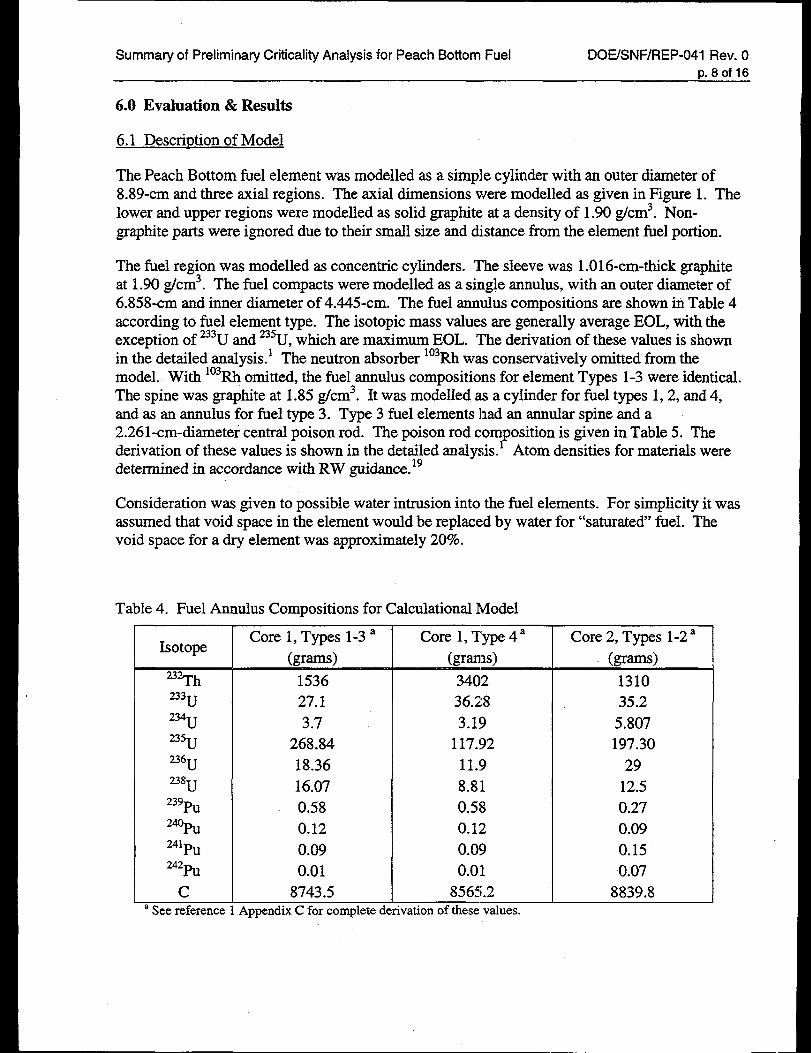
6.1 Description of Model
The Peach Bottom fuel element was modelled as a simple cylinder with an outer diameter of8.89-cm and three axial regions. The axial dimensions were modelled as given in Figure 1. Thelower and upper regions were modelled as solid graphite at a density of 1.90 g/cm3. Non-graphite parts were ignored due to their small size and distance from the element fuel portion.
The fuel region was modelled as concentric cylinders. The sleeve was 1.016-cm-thick graphiteat 1.90 g/cm3. The fuel compacts were modelled as a single annulus, with an outer diameter of6.858-cm and inner diameter of 4.445-cm. The fuel ammlus compositions are shown in Table 4according to fuel element type. The isotopic mass values are generally average EOL, with theexception of 233Uand 235U,which are maximum EOL. The derivation of these values is shownin the detailed analysis. 1 The neutron absorber *03Rhwas conservatively omitted from themodel. With 1°3Rhomitted, the fbel annulus compositions for element Types 1-3 were identical.The spine was graphite at 1.85 g/cm3. It was modeiled as a cylinder for l%eltypes 1,2, and 4,and as an annulus for fuel type 3. Type 3 fuel elements had an annular spine and a2.261 -cm-diameter central poison rod. The poison rod com osition is given in Table 5. Thederivation of these values is shown in the detailed analysis. ? Atom densities for materials weredetermined in accordance with RW guidance.lg
Consideration was given to possible water intrusion into the I%elelements. For simplicity it wasassumed that void space in the element would be replaced by water for “saturated” fuel. Thevoid space for a dry element was approximately 2070.
Table 4. Fuel Anm.dus Compositions for Calculational Model
Isotope
‘%h233U
234u235u236u238u
239PU
2%
241PU242PU
caSeereference
Core 1, Types 1-3a(grams)
153627.1
3.7268.84
18.3616.07
0.580.12
0.090.01
8743.5AppendixC forcompletede
Core 1, Type 4 a Core 2, Types 1-2a(grams) (grams)
340236.28
3.19117.!92
11.9
8.810.580.120.09
0.018565.2
ivationof thesevalues.
131035.2
5.807197.30
29
12.50.270.09
0.150.07
8839.8
Summary of Preliminary Criticality Analysis for Peach Bottom Fuel DOE/SNF/REP-041 Rev. O
p.9of16
Table 5. Core 1 Type 3 Poison Rod Composition
LLL&i_la See reference 1 Appendix C for complete
derivation of these values.
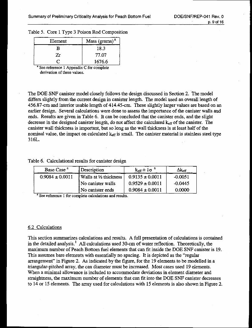
The DOE SNF canister model closely follows the design discussed in Section 2. The modeldiffers slightly from the current design in canister length. The model used an overall length of456.87-cm and interior usable length of 414.45-cm. These slightly larger values are based on anearlier design. Several calculations were done to assess the importance of the canister walls andends. Results are given in Table 6. It can be concluded that the canister ends, and the slightdecrease in the designed canister length, do not affect the calculated ~ff of the canister. Thecanister wall thickness is important, but so long as the wall thickness is at least half of thenominal value, the impact on calculated ~ff is small. The canister material is stainless steel type316L.
Table 6. Calculational results for canister design
I Base Case a IDescription IG?ff=k 10 a &.ff
0.9084 A0.0011 Walls at% thickness 0.9135 * 0.0011 -0.0051No canister walls 0.9529 A 0.0011 -0.0445No canister ends 0.9084 a 0.0011 0.0000
aSeereference1forcompletecalculationsandresults.
6.2 Calculations
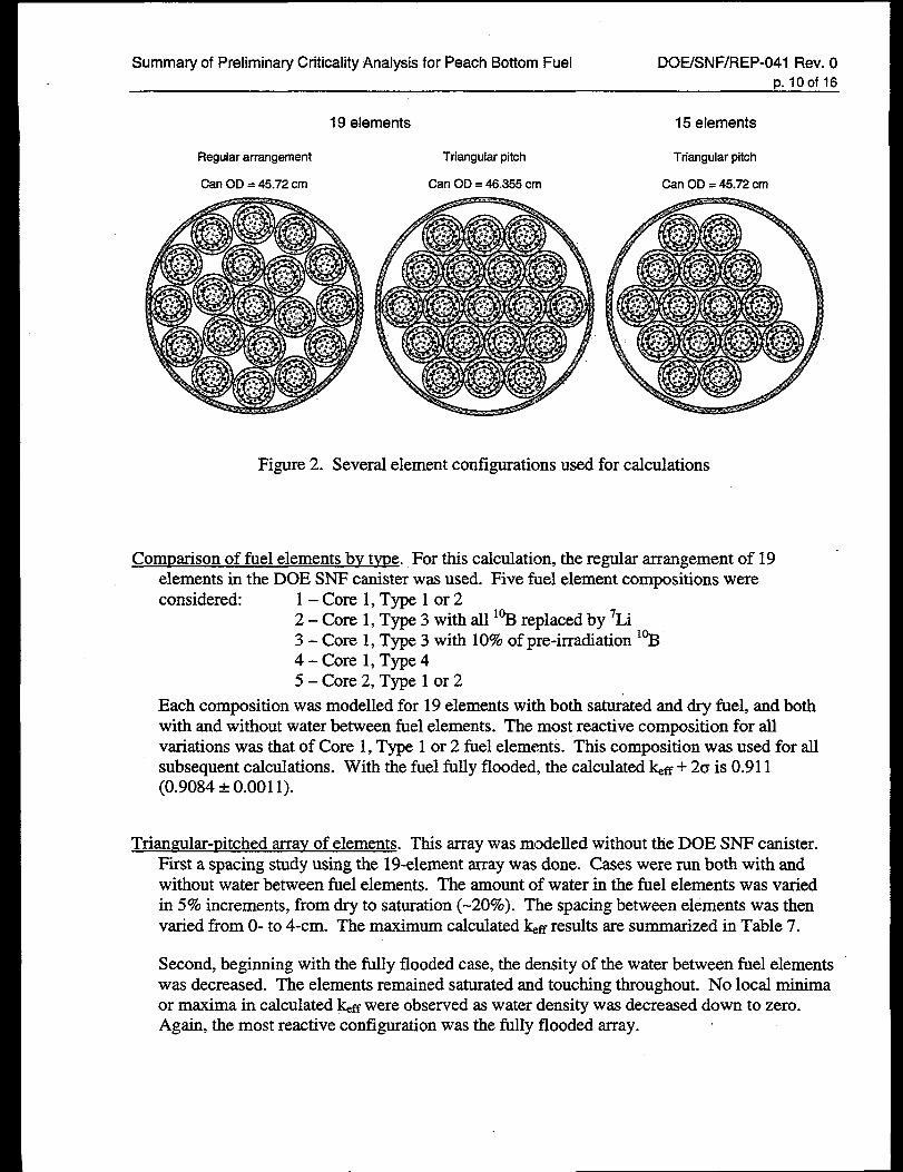
This section summarizes calculations and results. A full presentation of calculations is containedin the detaded analysis. 1 AIl calculations used 30-cm of water reflection. Theoretically, themaximum number of Peach Bottom fuel elements that can fit inside the DOE SNF canister is 19.This assumes bare elements with essentially no spacing. It is depicted as the “regulararrangement” in Figure 2. As indicated by the figure, for the 19 elements to be modelled in atriangular-pitched array, the can diameter must be increased. Most cases used 19 elements.When a minimal allowance is included to accommodate deviations in element diameter andstraightness, the maximum number of elements that can fit into the DOE SNF canister decreasesto 14 or 15 elements. The array used for calculations with 15 elements is also shown in Figure 2.
Summary of Preliminary Criticality Analysis for Peach Bottom Fuel DOE/SNF/REP-041 Rev. O
p.10of 16
19 elements
Regular arrangement
Can OD = 45.72 cm
Triangular pitch
Can OD = 46.355 cm
15 elements
Triangular pitch
Can OD. 45.72 cm
.
Figure 2. Several element configurations used for calculations
Comparison of fuel elements bv type. For this calculation, the regular arrangement of 19elements in the DOE SNF canister was used. Five fuel element compositions wereconsidered: 1 –Core l, Type 1 or2
2- Core 1, Type 3 with all 1% replaced by 7Li3 – Core 1, Type 3 with 109%of pre-irmdiation *!B4- Core 1, Type 45 – Core 2, Type 1 or 2
Each composition was modelled for 19 elements with both saturated and dry fuel, and bothwith and without water between fuel elements. The most reaetive composition for allvariations was that of Core 1, Type 1 or 2 fiel elements. This composition was used for allsubsequent calculations. With the fuel fully flooded, the calculated ~ff+20is0.911(0.9084 A 0.001 1).
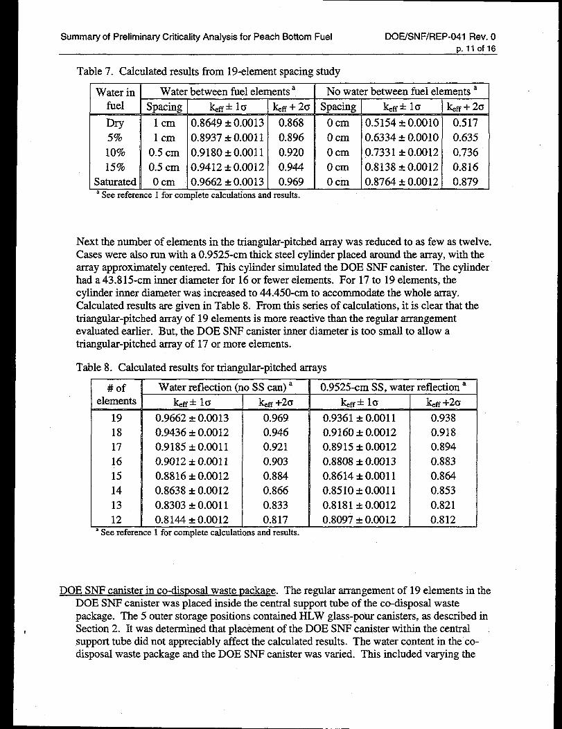
Triamzular-uitched array of elements. This array was modelled without the DOE SNF canister.First a spacing study using the 19-element array was done. Cases were run both with andwithout water between fuel elements. The amount of water in the fuel elements was variedin 5% increments, from dry to saturation (-20%). The spacing between elements was thenvaried from O-to 4-cm. The maximum calculated ~ results are summarized in Table 7.
Second, beginning with the fully flooded case, the density of the water between fuel elementswas decreased. The elements remained saturated and touching throughout. No local minimaor maxima in calculated &ffwere observed as water density was decreased down to zero.Again, the most reactive configuration was the fulIy flooded array.
r
Summary of Preliminary Criticality Analysis for Peach Bottom Fuel DOE/SNF/REP-041 Rev. On.llof16
Table 7. Calculated results from 19-element spacing study
Water in ! Water between fuel elements a ~ No water between fuel elements a—.-. -— H s
Dry
I1 cm 0.8649&0.0013 0.868
5!% 1cm 0.8937 k 0.0011 0.896
~a See reference 1 for complete calculations and results.
Ocm
Ocm
OcmOcm
Ocm
&ff* 10 &ff + 2G
0.5154 &0.0010 0.5170.6334 * 0.0010 0.635
0.7331 A0.0012 0.7360.8138&0.0012 0.8160.8764 * 0.0012 ().879
Next the number of elements in the triangular-pitched array was reduced to as few as twelve.Cases were also run with a 0.9525-cm thick steel cylinder placed around the array, with thearmy approximately centered. This cylinder simulated the DOE SNF canister. The cylinderhad a 43.815-cm inner diameter for 16 or fewer elements. For 17 to 19 elements, thecylinder inner diameter was increased to 44.450-cm to accommodate the whole array.Calculated results are given in Table 8. From this series of calculations, it is clear that thetriangular-pitched array of 19 elements is more reactive than the regular arrangementevaluated earlier. But, the DOE SNF canister inner diameter is too small to allow atriangular-pitched array of 17 or more elements.
Table 8. Calculated results for triangular-pitched arrays
#ofelements
1918171615141312
Water reflection (
km+ 10
0.9662 A0.00130.9436 A 0.00120.9185&0.00110.9012 * 0.00110.8816 * 0.00120.8638 * 0.00120.8303 A 0.00110.8144 * 0.0012
=See reference 1 for complete calculat
)Ss can) ak@ +20
0.9690.9460.9210.9030.8840.8660.8330.817
ns and results.
0.9525-em SS, watt
keff+ la
0.9361 &0.00110.9160 A 0.00120.8915 A 0.00120.8808 &0.0013
0.8614 * 0.00110.8510 &0.0011
0.8181 * 0.00120.8097 A 0.0012
reflection a
l@ +20
0.9380.9180.8940.8830.8640.853
0.8210.812
DOE SNF canister in co-disPosal waste uacka~e. The regular arrangement of 19 elements in theDOE SNF canister was placed inside the central support tube of the co-disposal wastepackage. The 5 outer storage positions contained HLW glass-pour canisters, as described inSection 2. It was determined that placement of the DOE SNF canister within the centralsupport tube did not appreciably affect the calculated results. The water content in the co-disposal waste package and the DOE SNF canister was varied. This included varying the
Summary of Preliminary Criticality Analysis for Peach Bottom Fuel DOE/SNF/REP-041 Rev. O~. 120f 16
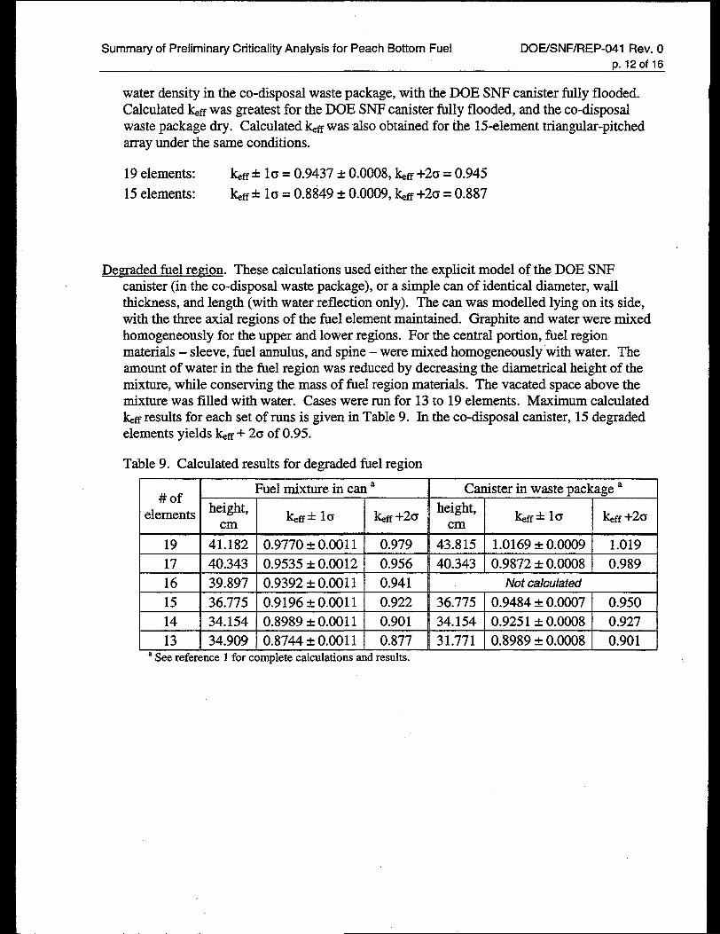
water density in the co-disposal waste package, with the DOE SNF canister filly flooded.Calculated kff was greatest for the DOE SNF canister filly flooded, and the co-disposalwaste package dry. Calculated ~ff was also obtained for the 15-element triangular-pitchedarray under the same conditions.
19 elements: ~ti+ 16 = 0.9437 &0.0008, ~fi +2c = 0.945
15 elements: ~fi+ 10 = 0.8849 &0.0009, ~fi+20 = 0.887
Demaded fuel region. These calculations used either the explicit model of the DOE SNFcanister (in the co-disposal waste package), or a simple can of identical diameter, wallthickness, and length (with water reflection only). The can was modelled lying on its side,with the three axial regions of the fuel element maintained. Graphite and water were mixedhomogeneously for the upper and lower regions. FOI:the central portion, fbel regionmaterials – sleeve, fiel annulus, and spine – were mixed homogeneously ‘withwater. Theamount of water in the I%elregion was reduced by decreasing the diametrical height of themixture, while conserving the mass of fiel region materials. The vacated space above themixture was filled with water. Cases were run for 13 to 19 elements. Maximum calculated~ff results for each set of runs is given in Table 9. In the co-disposal canister, 15 degradedelements yields kfi + 2CJof 0.95.
Table 9. Calculated results for degraded fuel region
Fuel mixture in can a Canister in waste package a#of
height, height,elements I@+ 10 &ff+20 &ff* 10 &ff +20cm cm
19 ~ 41.182 I 0.9770 *0.0011 I 0.979 ~ 43.815 I 1.0169 *0.0009 I 1.019 Is 1 n , 1
17 40.343 0.9535 * 0.0012 0.956 I 40.343 I 0.9872* 0.0008 I 0.989
16 39.897 0.9392 * 0.0011 0.941 Not calculatedn 1 , 0
15 I 36.775 I 0.9196& 0.0011 I 0.922 I 36.775 I 0.9484* 0.0007 I 0.950
14 ~ 34.154 [ 0.8989* 0.0011 \ 0.901 ~ 34.154 I 0.9251* 0.0008 I 0.927 I13 I 34.909 I 0.8744& 0.0011 I 0.877 I 31.771 I 0.8989* 0.0008 I 0.901
aSeereference1forcompletecalculationsandresults.
Summary of Preliminary Criticality Analysis for Peach Bottom Fuel DOE/SNF/REP-041 Rev. O
p. 130f ?6
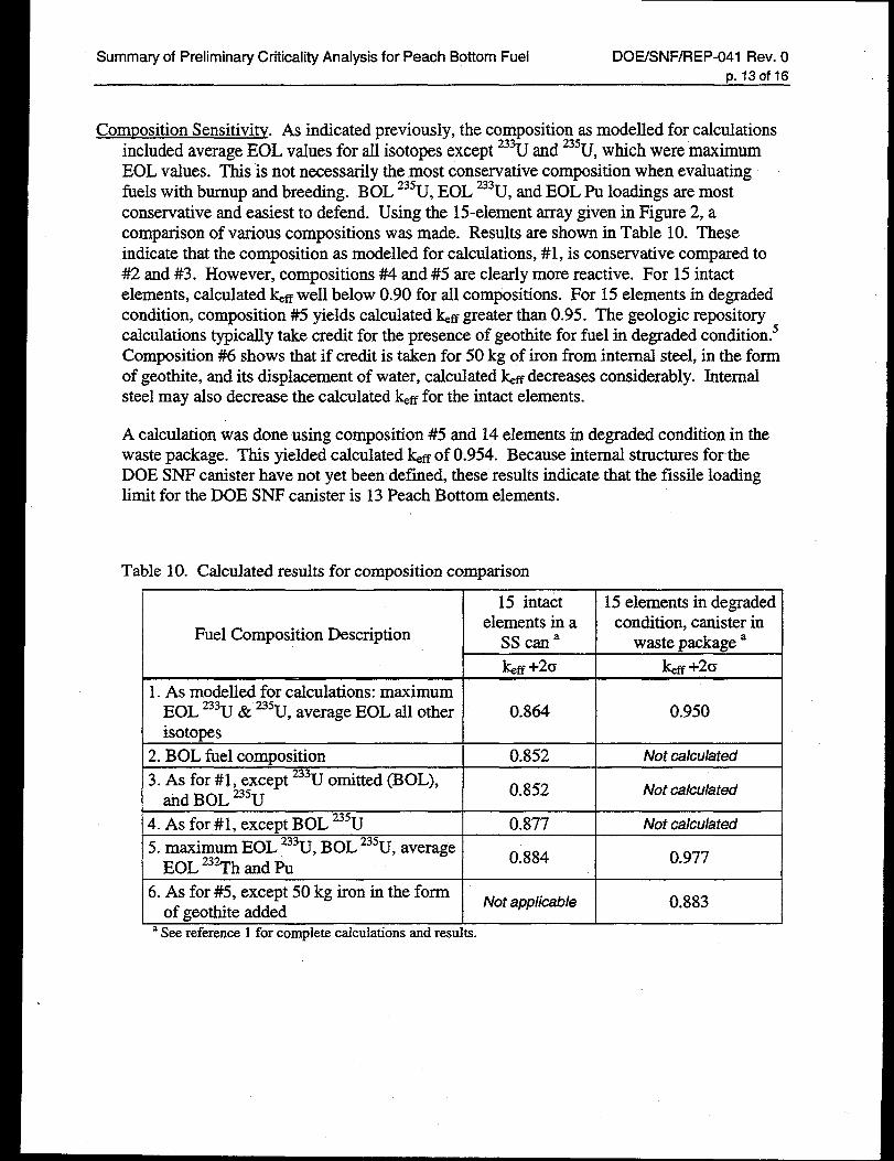
Composition Sensitivity. As indicated previously, the composition as modelled for calculationsincluded average EOL values for all isotopes except 233Uand 235U,which were maximumEOL values. This is not necessarily the most conservative composition when evaluatingfuels with burnup and breeding. BOL 235U,EOL 233U,and EOL Pu loadings are mostconservative and easiest to defend. Using the 15-element array given in Figure 2, acomparison of various compositions was made. Results are shown in Table 10. Theseindi~ate that the compositi~n as modelled for calculations, #1, is conservative compared to#2 and #3. However, compositions #4 and #5 are clearly more reactive. For 15 intacteIements, calculated ~ff well below 0.90 for all compositions. For 15 elements in degradedcondition, composition #5 yields calculated ~ff greater than 0.95. The geologic repositorycalculations typically take credit for the presence of geothite for fuel in degraded condition.5Composition #6 shows that if credit is taken for 50 kg of iron from internal steel, in the formof geothite, and its displacement of water, calculated ~ff decreases considerably. Internalsteel may also decrease the calculated ~ff for the intact elements.
A calculation was done using composition #5 and 14 elements in degraded condition in thewaste package. This yielded calculated ~ff of 0.954. Because internal structures for theDOE SNF canister have not yet been defined, these results indicate that the fissile loadinglimit for the DOE SNF canister is 13 Peach Bottom elements.
Table 10. Calculated results for composition comparison
15 intact 15 elements in degraded
Fuel Composition Descriptionelements in a condition, canister in
Sscana waste package a
I la +20 I lceff+20
1. As modelled for calculations: maximumEOL 233U& 235U,average EOL all other 0.864 0.950isotopes
2. BOL fuel composition 0.852 Not calculatedL .
3. As for #1, except 233Uomitted (BOL),0.852 Not calculated
ad BOL 235U
4. As for #1, except BOL 235U 0.877 Not calculated
5. maximum EOL ‘3U, BOL 235U,averageEOL 23% and 1%
0.884 0.977
6. As for #5, except 50 kg iron in the formNot app/icab/e 0.883
of geothite addedaSeereference1forcompletecalculationsandresults.
Summary of Preliminary Criticality Analysis for Peach Bottom Fuel DOE/SNF/REP-041 Rev. O~. 140f 16
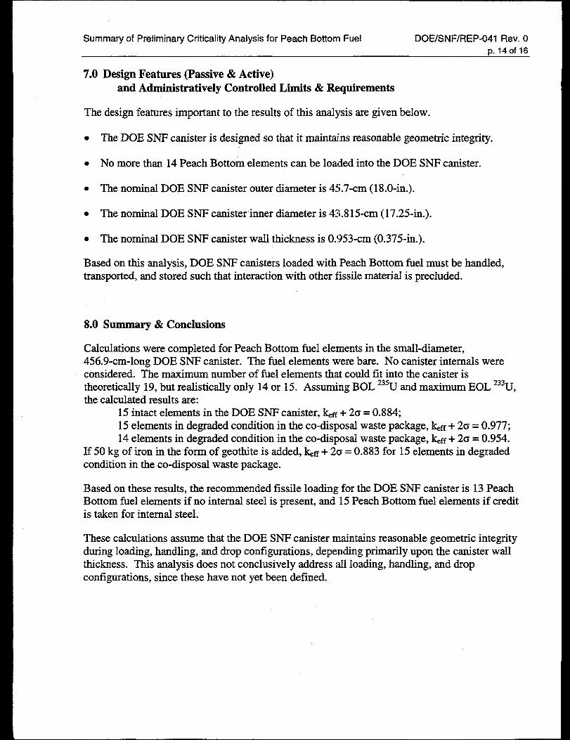
7.0 Design Features (Passive & Active)and Administratively Controlled Limits & Requirements
The design features important to the results of this analysis are given below.
. The DOE SNF canister is designed so that it maintains reasonable geometric integrity.
● No more than 14 Peach Bottom elements can be loaded into the DOE SNF canister.
. The nominal DOE SNF canister outer diameter is 45.7-cm (18.O-in.).
. The nominal DOE SNF canister inner diameter is 43.815-cm (17.25-in.).
. The nominal DOE SNF canister wall thickness is 0.953-cm (0.375-in.).
Based on this analysis, DOE SNF canisters loaded with Peach Bottom fhel must be handled,transported, and stored such that interaction with other fissile material is precluded.
8.0 Summary & Conclusions
Calculations were completed for Peach Bottom fuel elements in the small-diameter,456.9-cm-long DOE SNF canister. The fiel elements were bare. No canister internals wereconsidered. The maximum number of fiel elements that could fit into the canister istheoretically 19, but realistically only 14 or 15. Assuming BOL 235Uand maximum EOL ‘3U,the calculated results are:
15 intact elements in the DOE SNF canister, ~ff + 20 = 0.884;15 elements in degraded condition in the co-disposal waste package, ~ff + 2cJ= 0.977;14 elements in degraded condition in the co-disposal waste package, ~ff + 2a = 0.954.
If 50 kg of iron in the form of geothite is added, &ff + 20 = 0.883 for 15 elements in degradedcondition in the co-disposal waste package.
Based on these results, the recommended fissile loading for the DOE SNF canister is 13 PeachBottom fuel elements if no internal steel is present, and 15 Peach Bottom fuel elements if creditis taken for internal steel.
These calculations assume that the DOE SNF canister maintains reasonable geometric integrityduring loading, handling, and drop configurations, depending primarily upon the canister wallthickness. This analysis does not conclusively address all loading, handling, and dropconfigurations, since these have not yet been defined.
—
Summary of Preliminary Criticality Analysis for Peach Bottom Fuel DOE/SNF/REP-041 Rev. Op. 150f 16
9.0 References
1. D..J. Henrikson, Prelimina~ Criticality Safety Analysis for Peach Bottom Fuel in the DOEStandardized Spent Nuclear Fuel Canister, DOEISNWREP-036 Rev. O,U.S. DOE NationalSpent Nuclear Fuel Program, Lockheed Martin Idaho Technologies Company (Idaho Falls,ID) draft January 1999.
2. Civilian Radioactive Waste Management System (CRWMS) Management and OperatingContractor (M&O), Quali~ Assurance Requirements and Description, DOEA?W-0333P,Rev. 8, M&O (Las Vegas, NV), June 5, 1998.
3. R.P. Morissette, N. Tomsio, and J. Razvi, Characterization of Peach Bottom Unit 1 Fuel,GA-C18525, GA Technologies (San Diego, CA), October 1986.
4. Preliminary Design Specification for Department of Energy Standardized Spent NuclearFuel Canisters, DOE/SNF/REP-011 Rev. 1, U.S. DOE National Spent Nuclear FuelProgram, Lockheed Martin Idaho Technologies Company (Idaho Falls, ID), November 1998.
5. L.M. Montierth, Fast Flux Test Facility (FFTF) Reactor Fuel Criticality Calculations,Document Identifier BBAOOOOOO-01717-021O-OOO16 REV 00A, CRWMS M&O,Preliminary Check Copy.
6. American Nuclear Society Standards Committee Subcommittee ANS-8, Nuclear CriticalitySafety in Operations with Fissionable Materials Outside Reactors, an American NationalStandard, ANSI/ANS-8. 1-1998, American Nuclear Society (La Grange Park, IL), approved1998.
7. American Nuclear Society Standards Committee Working Group ANS-8.7, Guide forNuclear Criticality Safety in the Storage of Fissile Materials, an American NationalStandard, N16.5-1975/ANS-8.7 (R 1987), American Nuclear Society (La Grange Park, IL),approved April 12, 1975.
8. American Nuclear Society Standards Committee Subcommittee ANS-8, AdministrativePractices for Nuclear Criticali~ Safety, an American National Standard, ANSYANS-8. 19-1996, American Nuclear Society (La Grange Park, IL), approved April 17, 1996.
9. U.S. Department of Energy, DOE Standard: Guidelines for Preparing Criticali~ SafetyEvaluations at Department of Energy Non-Reactor Nuclear Facilities, DOE-STD-3007-93,Change Notice No. 1, Office of Scientific and Technical Information (Oak Ridge, TN),September 1998.
10. iklCNP~~ – A General Monte Carlo N-Particle Transport Code, Version 4B, CCC-660/MCNP4B2, LA-12625-M, contributed by Los Alamos National Laboratory to the RSICComputer Code Collection, Oak Ridge National Laboratory, March 1997.
11. S. Goluoglu and J.A. McClure, So@are Qualification Report for MCNP Version 4B2, AGeneral Monte Carlo N-Particle Transpoti Code, Computer Software Configuration Item30033 V4B2LV, Document Identifier 30033-2003 REV 01, CRWMS M&O (Las Vegas,NV), April 1998.
12. L.L. Montierth and V.L. Putman, MCNP4B2 as Transferred So~are for the HIC Project,DOEKNWDSN-O1O Rev. O,U.S. DOE National Spent Nuclear Fuel Program, LockheedMartin Idaho Technologies Company (Idaho Falls, ID) September 1998.
13. W.C. Redman et al., Critical Experiments with Thoria-Urania Fuel in Heavy Water,ANL-6378, Argonne National Laboratory (Argonne, IL) December 1961.
Summary of Preliminary Criticality Analysis for Peach Bottom Fuel DOE/SNF/REP-041 Rev. OD. 160f 16
14.V.F. Dean, “Critical Arrays of Polyethylene-Moderated U(30)FA-PolytetrafluoroethyleneOne-Inch Cubes,” IEU-COMP-THERM-001 Rev. O,March31, 1995. InternationalHandbook of Evaluated Criticali~ Safety Benchmark Experiments Volume 111,NEA/NSC/DOC(95)/03AII, September 1998 edition.
15. K. Woods, “Graphite and Water Moderated NRX-A3 and NRX-A4 Assemblies;’HEU-COMP-THERM-002 Rev. O,September 30, 1!398. International Handbook ofEvaluated Criticali~ Safety Benchmark Experiments Volume II, NEAlNSClDOC(95)/03111,September 1998 edition.
16. R.W. Brewer, “Benchmark Critical Experiment of a Thorium Reflected Plutonium Sphere:’PU-MET-FAST-O08 Rev. 1, December31, 1996. International Handbook of EvaluatedCriticaliQ Safely Benchmark Experiments Volume I, NEA/NSC/DOC(95)/03/1, September1998 edition.
17. J.L. Sapir, “Unreflected Spheres of 233UNitrate Solutions:’ U233-SOL-THERM-O01 Rev. O,August 31, 1996. International Handbook of Evaluated Cn”ticali@ Safety BenchmarkExperiments Volume V, NEA/NSC/DOC(95)/03/V, September 1998 edition.
18. J.L. Sapir, “A 48-Inch-Diameter Unreflected Sphere of 233UNitrate Solution,”
U233-SOL-THERM-O08 Rev. O, September 30, 1997. International Handbook of EvaluatedCriticali~ Safety Benchmark Experiments Volume V, NEA/NSCiDOC(95)/03/V, September1998 edition.
19. D. A. Thomas, Material Compositions and Number Densities For Neutronics Calculations(SCPB:N\A), BBAOOOOOO-01717-0200-OOO02 Rev. 00, CRWMS M&O (Las Vegas, NV),January 1996.