high-frequency protection concepts for the electric...
TRANSCRIPT

Metatech Corporation • 358 S. Fairview Ave., Suite E • Goleta, California • (805) 683-5681 Registered Mail: P.O. Box 1450 • Goleta, California 93116
Meta-R-324
High-Frequency Protection Concepts for the Electric Power Grid William Radasky Edward Savage Metatech Corporation 358 S. Fairview Ave., Suite E Goleta, CA 93117 January 2010 Prepared for Oak Ridge National Laboratory Attn: Dr. Ben McConnell 1 Bethel Valley Road P.O. Box 2008 Oak Ridge, Tennessee 37831 Subcontract 6400009137

Metatech
Front Matter
i
FOREWORD
This report is intended to provide a set of high-frequency (> 1 MHz) electromagnetic (EM) protection concepts for the U.S. power grid. The EM threats of interest are for the early-time (E1) high-altitude electromagnetic pulse (HEMP) produced from a nuclear detonation at high altitudes, and intentional electromagnetic interference (IEMI) from EM weapons. While these threats are low probability, they are likely to have a high impact unless some effort is made to protect against them. This report begins in Section 1 with an introduction. Section 2 summarizes recent reports with respect to the E1 HEMP threat and its impacts on the power delivery system. Section 3 summarizes recent reports with respect to the IEMI threat and its impacts on the power delivery system. Section 4 identifies the protection needs for both HEMP and IEMI and Section 5 identifies a set of protection plans for each of the identified threats and power system aspects. A bibliography is provided at the end of the report.

Metatech
Front Matter
ii
Table of Contents Section Page 1 Introduction 1-1 2 Summary of E1 HEMP Environments and Impacts 2-1
2.1 E1 HEMP Environment 2-1 2.2 E1 HEMP Coupling 2-3 2.3 E1 HEMP Impacts on the Power Grid 2-4
2.3.1 High Voltage Substation Controls and Communications .................... 2-5 2.3.2 Power Generation Facilities................................................................. 2-9 2.3.3 Power Control Centers......................................................................... 2-9 2.3.4 Distribution Line Insulators ................................................................. 2-9 2.3.5 Distribution Transformers.................................................................. 2-13
3 Summary of the IEMI Environment and Impacts 3-1 3.1 IEMI Environment 3-1 3.2 IEMI Coupling 3-2 3.3 IEMI Impacts on the Power Grid 3-2
3.3.1 High Voltage Substation Controls and Communications .................... 3-2 3.3.2 Power Generation Facilities................................................................. 3-3 3.3.3 Power Control Centers......................................................................... 3-3 3.3.4 Distribution Line Insulators ................................................................. 3-4 3.3.5 Distribution Transformers.................................................................... 3-4
4 Protection Concepts 4-1 4.1 Basic High Frequency Protection Concepts 4-1 4.2 Applications of High Frequency EM Protection 4-4 4.3 Applications of High Frequency EM Protection 4-9 4.4 IEC SC 77C Standards 4-9
5 Protection Applications 5-1 5.1 HEMP Protection Applications 5-1
5.1.1 High Voltage Substation Controls and Communications .................... 5-1 5.1.2 Power Generation Facilities................................................................. 5-1 5.1.3 Power Control Centers......................................................................... 5-2 5.1.4 Distribution Line Insulators ................................................................. 5-2 5.1.5 Distribution Transformers.................................................................... 5-3
5.2 IEMI Protection Applications 5-3 5.2.1 High Voltage Substation Controls and Communications .................... 5-3 5.2.2 Power Generation Facilities................................................................. 5-4 5.2.3 Power Control Centers......................................................................... 5-4 5.2.4 Distribution Line Insulators ................................................................. 5-4 5.2.5 Distribution Transformers.................................................................... 5-4
Bibliography B-1

Metatech
Front Matter
iii
List of Figures Figure Page 2-1 The various parts of a generic HEMP signal. ........................................................ 2-1 2-2 Comparison of HPEM environments..................................................................... 2-2 2-3 E1 HEMP exposed regions for several burst heights (red values), for a nuclear
burst over the central U.S. .................................................................................. 2-2 2-4 Capacitive (electric) coupling to a short cable. ..................................................... 2-4 2-5 Inductance (magnetic) coupling to a short cable. .................................................. 2-4 2-6 Exposure area for E1 HEMP burst at 170 km over Ohio. ..................................... 2-5 2-7 1765 EHV substations at 345 kV and higher (83%) exposed by the burst in
Figure 2-6............................................................................................................ 2-6 2-8 Grounding of control cable shields and j-boxes in control building. .................... 2-7 2-9 Distribution of control cables within building to cabinets..................................... 2-2 2-10 A typical above ground 15 kV distribution geometry in the U.S. ....................... 2-11 4-1 Electric leakage through an aperture. .................................................................... 4-1 4-2 Magnetic leakage through an aperture................................................................... 4-2 4-3 External cabling with poor termination at the subsystem...................................... 4-3 4-4 Options for EM hardening. .................................................................................... 4-4 4-5 Application of zones for EM protection. ............................................................... 4-5 4-6 Engineering design of EM shielding and conductor protection. ........................... 4-6 4-7 Management of cables to reduce the impact of high-frequency EM coupling...... 4-7 4-8 Example of high-frequency EM mitigation application. ....................................... 4-8 4-9 Setup to perform low level cw shielding test......................................................... 4-8 4-10 List of publications for IEC SC 77C dealing with HEMP and IEMI on civil
systems.............................................................................................................. 4-10

Metatech
Front Matter
iv
List of Tables Table Page 2-1 Summary of the distribution systems for the U.S. power grid............................ 2-10 2-2 Ratio of peak CFO voltage for steep front, short duration pulse to lightning
impulse............................................................................................................ 2-11 2-3 Peak voltage of flashover for insulators under operational voltage.................... 2-12

Metatech
Section 1 – Introduction 1-1
Section 1 Introduction
This report begins by summarizing the understanding of the threats of the early-time (E1) high-altitude electromagnetic pulse (HEMP) and intentional electromagnetic interference (IEMI) and their impacts on the U.S. electric power system. This is accomplished mainly through referencing other recent reports that were developed as part of this program for Oak Ridge National Laboratory (ORNL). Given the threats and the impacts, the main focus of this report is to identify both general and specific protection methods that may be applied to allow the U.S. power grid to operate in the face of these two different threats. It is noted that while these two different electromagnetic threats are greatly different in how they are created, the means to protect electronic systems from them is similar due to the fact that particular electromagnetic protection methods will be effective against both threats. Section 2 follows with a summary of the E1 HEMP threat and its impacts on the power system. Section 3 provides the same information for the threat of IEMI. Section 4 identifies a series of electromagnetic protection concepts that will be useful to eliminate high-frequency electromagnetic interference in general. Section 5 takes these general protection concepts and indicates how they should be applied to provide protection for the impacts identified as part of this ORNL program. A bibliography is found at the end of the report.

Metatech
Section 2 – Summary of E1 HEMP Environment and Impacts 2-1
Section 2 Summary of E1 HEMP Environment and Impacts
2.1 E1 HEMP Environment E1 HEMP is the first part of the intense electromagnetic signal that is generated by a nuclear burst that explodes high above the Earth – generally said to be “above the atmosphere” or in space. In order to generate a significant field, the usual altitude definition for the HEMP burst is 30 km or higher, although this definition is not precise. E1 HEMP is a fast narrow pulse, typically possessing high peak electromagnetic field levels not commonly seen from natural events. Figure 2-1 shows a generic waveform for a full HEMP signal – E1 HEMP is the “prompt gamma signal” part that lasts out to about a microsecond. The rest of the signal is much lower in magnitude, but also much longer in time extent. More details concerning the phenomenology of creating E1 HEMP can be found in the bibliography.
Figure 2-1. The various parts of a generic HEMP signal.
Figure 2-2 compares a generic example of the E1 HEMP portion of the frequency spectrum as compared to the EM fields from a nearby cloud-to-ground lightning strike at lower frequencies and from IEMI threats (wideband and narrowband) at higher frequencies. In comparing these high power electromagnetic (HPEM) threats, it is clear that HEMP is dominant between 1 MHz and 300 MHz to 1 GHz (depending on the actual HEMP threat waveform).

Metatech
Section 2 – Summary of E1 HEMP Environment and Impacts 2-2
Figure 2-2. Comparison of HPEM environments.
Figure 2-3 illustrates the area coverage aspect of the E1 HEMP, which shows that higher bursts create greater area coverage, however generally with lower field levels for the same threat weapon.
Figure 2-3. E1 HEMP exposed regions for several burst heights (red values), for a nuclear burst over the central U.S.

Metatech
Section 2 – Summary of E1 HEMP Environment and Impacts 2-3
The E1 HEMP field is generated in a way that it is linearly polarized with an orientation of the electric field vector perpendicular to the direction of propagation and the local Earth’s magnetic field. Within the incident plane, which contains the E1 HEMP fields, the electric field can be separated into the transverse magnetic (TM) and transverse electric (TE) components. For coupling to the cables and equipment near the Earth’s surface, these components are often further separated into vertical and horizontal components, as the Earth’s surface is a more useful geometry to consider. It is important to recognize that these E1 fields are propagating as a local plane wave with virtually no variation with distance over many kilometers.
2.2 E1 HEMP Coupling Electromagnetic signals generate voltages and currents on conductors exposed to the fields – so the E1 HEMP time-varying fields that encounter a conductor induce time-varying voltage and current signals on that conductor. Vulnerability issues occur when the conductor connects to a circuit with parts that could be destroyed. Coupling is a full electromagnetic effect, but often can be thought of in terms of individual electric (capacitive – Figure 2-4) or magnetic (inductive – Figure 2-5) coupling. In these figures we show a cable connected to a metal plate at both ends, such as the shields of a shielded cable that is fully bonded to the metal enclosures where it connects. The same effect applies if the cable is unshielded, except the currents and voltages signals would be seen directly on circuits attached to the cable ends (with the circuit impedances governing the exact currents and voltages). For capacitive coupling the electric field rearranges electric charges on the conductor – those charge movements are currents, and the force that moves them is a voltage. Similarly, there is an EMF (voltage) generated in the conductive loop by the time rate of change of the total magnetic flux through the loop, and a current is driven in response. There are also couplings that are electromagnetic in nature, such as high frequency wave coupling to long cables or antennas. This is exactly the process by which receiving antennas work, and so they will pick up E1 HEMP energy by their very nature. But any conductive object, not just antennas, will have induced signals. The coupling process for antennas and long lines can be very complex, depending on details of exactly which way the incident EM wave is propagating, and the field polarization (which direction the E and H fields point). The E and H must be in the plane perpendicular to the propagation direction, and H must be perpendicular to E in that plane, but otherwise there is no restriction on where E points within the plane (this defines the polarization of the field).

Metatech
Section 2 – Summary of E1 HEMP Environment and Impacts 2-4
Figure 2-4. Capacitive (electric) coupling to a short cable. The electric field (E) induces the voltages and currents shown.
Figure 2-5. Inductance (magnetic) coupling to a short cable. The magnetic field (H) induces the voltages and currents shown.
2.3 E1 HEMP Impacts on the Power Grid In this section we consider the likely impacts of the E1 HEMP on various parts of the electric power system. Metatech has performed a large number of test and analysis studies dealing with the U.S. power grid and has determined that there are five main areas of concern:
1. High voltage substation controls and communications 2. Power generation facilities 3. Power control centers 4. Distribution line insulators 5. Distribution transformers
It has been determined that the main pathway for the E1 HEMP to reach the electronic equipment that control the operation of the grid is through the coupling of the E1 HEMP fields to cables and wiring, producing conducted transients that can exceed the withstand capability of the connected electronics. In addition, the distribution line insulators and transformers connect to the aboveground electric wires, and so are also influenced by the coupled E1 HEMP fields. Details concerning the coupling to cables and the levels of equipment vulnerability for the cases that follow are found in the bibliography references.

Metatech
Section 2 – Summary of E1 HEMP Environment and Impacts 2-5
2.3.1 High Voltage Substation Controls and Communications It is important to evaluate the E1 HEMP threat to high voltage power networks, and to develop protection methods to deal with the threat. High voltage power substations are especially at risk as they are usually operating without on-site personnel, and many substations will be exposed simultaneously (within one power cycle) with high-frequency electromagnetic fields from one high-altitude nuclear burst, as shown in Figures 2-6 and 2-7.
Figure 2-6. Exposure area for E1 HEMP burst at 170 km over Ohio.

Metatech
Section 2 – Summary of E1 HEMP Environment and Impacts 2-6
Figure 2-7. 1765 EHV substations at 345 kV and higher (83%) exposed by the burst in Figure 2-6.
The biggest E1 HEMP concern within a high voltage substation is not the high voltage transmission lines and transformers, but rather the low voltage sensor and control lines that extend from the transformer yard to the relays and other control electronics in the control building. Even if these cables are in metallic conduits above ground, usually these conduits are not effective electromagnetic shields at high frequencies. Currents and voltages coupled to an external conduit are likely to leak into the internal cables at the joints and at connection points to sensors and the controls. Theses sensor and control cables run back to the control building in underground trays that also are not well shielded and will allow E1 HEMP pickup on the cables themselves. The main concern involves the possibility that the E1 HEMP currents on the cables will propagate into the control buildings and to the relay and other equipment. Figure 2-8 shows the grounding process inside the control building where the control cables have their insulation stripped back and the shields are connected to ground cables. It is noted that the ground cables are on the order of 30 cm long (or longer), which provides a high impedance at high frequencies. While this is sufficient for lightning frequencies (typically below 1 MHz), this will enable a significant portion of the high-frequency E1 HEMP transients to continue to propagate on the signal wires inside the control facility instead of being directed to ground.

Metatech
Section 2 – Summary of E1 HEMP Environment and Impacts 2-7
Figure 2-8. Grounding of control cable shields and j-boxes in control building.
In Figure 2-9 cables extend from the j-boxes to the individual racks of equipment. These cables will carry any remaining high-frequency transients that were coupled to the cables outside, and they will also carry high-frequency transients coupled from the electromagnetic fields that propagate through the walls of the building. It is important to note that the direct coupling of E1 HEMP fields inside the building is strongly influenced by the construction type of the building. There are strong variations for the penetrating electric fields at frequencies above 10 MHz due to whether the building is made of concrete (with or without reinforced bars), bolted metal, or wood.

Metatech
Section 2 – Summary of E1 HEMP Environment and Impacts 2-8
Figure 2-9. Distribution of control cables within building to cabinets.
While these figures are provided to give an indication of the scope of the problem, it will be necessary to evaluate many factors that are common or different in various power substations in order to determine the seriousness of the E1 HEMP threat and to recommend protection techniques that are cost effective. Based upon coupling calculations it appears that levels up to 10 kV may be coupled to horizontal buried lines in a substation yard (although 20 kV is possible under some scenarios). HEMP voltage levels on the order of 70 kV may also be induced on vertical conduits. While the amount of these voltages that could propagate to the relays and other electronic control equipment is extremely variable, the fact that upsets on relays begin at 3.2 kV and damage to PLCs and PCs begin at approximately 0.5 kV, indicates a serious concern for the continued operation of the substations. Even if the cable penetrations to the control building are protected, there is still the problem of the penetration of the E1 HEMP fields inside and their coupling to the cables just above the electronic cabinets. The level of the field penetrating the building is completely dependent on the type of wall and ceiling construction; however, tests performed in the past on telephone switching centers indicated that voltage levels as high as 10 kV could be induced on cables. Depending on the way that the cables enter the cabinets (whether the cable shields are bonded to the cabinet shield or not) will determine if these voltages reach the electronic equipment ports inside.

Metatech
Section 2 – Summary of E1 HEMP Environment and Impacts 2-9
2.3.2 Power Generation Facilities Power generator facilities are similar to industrial processing plants in that they use PLCs (Programmable Logic Controllers) to control the flow of fuel and other aspects of the power generation process. As indicated in previous test programs, damage may occur for E1-like pulses at levels as low as 0.6 kV, although only one manufacturer’s equipment failed at that level; the other failed at 3.3 kV. Since power generators are manned, the impact of upset may not be as important as damage, however, the damage levels indicated are quite low. In addition, it is not expected that the cabling within the generator facility will be better protected than in a substation, so again levels of induced voltages as high as 70 kV may be coupled to vertical cables and 20 kV for horizontal buried cables in some generation facilities. 2.3.3 Power Control Centers Power control centers can be described as distributed computer facilities with many communications lines entering and leaving the facility. Since these facilities do not deal directly with high voltage transformers nearby, most of the computer equipment is not afforded the same basic level of immunity as those found in substations, or in power generation facilities for that matter. Equipment like the PC is likely to fail its communications port due to E1 HEMP at 0.5 kV, and other test data indicates that Ethernet ports are generally vulnerable at low levels. Given that ordinary building protection levels will typically allow up to 10 kV to be coupled to internal cables, this indicates a potential problem. An important factor to consider is the location and type of wall construction of control centers. A control center built below the surface of the Earth has much better natural shielding than one built above grade in a high-rise building. 2.3.4 Distribution Line Insulators Approximately 78% of all electric power delivery to end-users is delivered via 15 kV class distribution lines, as highlighted in Table 2-1. Figure 2-10 also illustrates a typical distribution feeder geometry that indicates the variation of the orientation of the lines for a single feeder. This shows that the likelihood for an optimum exposure of a segment of the line is high and that at some point along the feeder the maximum E1 HEMP voltage will be induced, creating a possible insulator flashover.

Metatech
Section 2 – Summary of E1 HEMP Environment and Impacts 2-10
Table 2-1. Summary of the distribution systems for the U.S. power grid. U.S. Power Distribution
• Distribution systems in the U.S. o 5, 15, 25 and 35 kV o 15 kV is 77.5% of all load o 35,000 to 40,000 distribution substations o Substation size varies from ~1 - 100 MVA with an average of 20 MVA
• Multiple feeders leave the substations
o 4 to 14 feeders per substation o Typically 300 line segments per feeder o 60 fault protection and isolation devices per feeder o Average 3 phase feeder length is 10.8 miles o 93% of all U.S. feeders are of overhead construction
• End users supplied by feeders
o 13.0% industrial load o 18.4% supply urban/commercial load o 11.9% rural load o 55.7% suburban load
Soderville Substation
Heavy Line is 3 Phase Feeder
Thin Line is Single Phase Tap Line
Figure 2-10. A typical aboveground 15 kV distribution geometry in the U.S.

Metatech
Section 2 – Summary of E1 HEMP Environment and Impacts 2-11
At present, considerable uncertainty exists as to whether the typical insulation capability of these distribution assets will be sufficient to withstand the induced overvoltages due to the E1 environment of a HEMP threat. Prior analysis of the E1 threat by Metatech indicated that induced overvoltages ranging from 200 kV to over 400 kV (depending on the scenario) can occur on these distribution lines over geographically widespread regions, and that if large scale distribution line insulator failure or flashover occurs, the impacted regions will likely experience power grid collapse, especially if many flashovers occur within 1 mile of many substations, where the fault current will be high. Typical insulation designs for distribution feeders usually are based upon testing of the 1.2 µs rise time impulse due to lightning (with a 50 µs pulse width). For these lightning impulses, typical pin insulator withstand generally starts at ~100 kV. It has generally been observed that the shorter duration pulse widths of the E1 HEMP threat will increase the level of the flashover voltage for these insulators, but the amount of increase was not well substantiated until further testing was performed. Two sets of experiments and results are summarized here. The first is work done by Dr. Stan Gryzbowski from Mississippi State University (MSU), using standard insulator test techniques and testing of a wide variety of insulators found in the U.S. power grid. He also examined variations due to polarity of the impulse and other factors such as wet insulators. All of the testing was performed without power on the insulator, which is the usual method for testing insulators in the United States. The MSU test results are summarized in Table 2-2, showing the ratio of the peak critical flashover (CFO) levels of the steep front flashover to the standard lightning tests. It is noted that in most cases the E1 HEMP related tests indicate that the peak HEMP voltage required is often less than a factor of 50% higher than the lightning BIL (Basic Insulation Level) tests, and with negative polarity it is only about 10% higher. The polymer suspension insulator appears to be more robust to E1 HEMP waveforms. With the typical lightning BIL about 100 kV, it is also recognized that apparently peak CFO voltages of much less than 200 kV are a concern for flashover.
Table 2-2. Ratio of peak CFO voltage for steep front, short duration pulse to lightning impulse.

Metatech
Section 2 – Summary of E1 HEMP Environment and Impacts 2-12
Due to the fact that the Soviet Union indicated that some distribution insulators were damaged (resulting in power lines dropping to ground) during their high-altitude nuclear tests in 1962, they developed the capability to perform power-on tests on power line insulators. This testing is very difficult, but it was decided by the EMP Commission that such testing should be done, and Metatech Corporation was the prime contractor for this test program. Lab experiments with fast rising (E1-like HEMP waveforms) were performed for a set of Russian glass and porcelain insulators. The main emphasis for these experiments was the fact that the tests were performed both with no power on the insulators and also with the insulators energized with a portion of an AC waveform up to 1,000 amperes. Tests performed power off showed fairly repeatable results for multiple pulses. When power on testing was performed, a few of the insulators were physically damaged by the follow-on power. In addition, there was substantial degradation of the performance of the insulators even after one test shot, as shown in Table 2-3.
Table 2-3. Peak voltage of flashover for insulators under operational voltage.
It is likely that the mechanism for destruction has to do with small defects in the manufacture of the insulators. The Russian experimental team tried to determine whether these defects were present before the testing, but they were not able to find a simple way to evaluate this aspect. An important aspect of the multiple flashover testing under power is that while we do not expect large numbers of pulses to expose the U.S. power grid, lightning pulses occur in many locations in the U.S. and could therefore expose many insulators to previous impulses without causing noticeable failures. Thus a future E1 HEMP pulse could be the second or third pulse that some insulators will observe. While this Russian test data is very dramatic, it is noted that the tests were performed on Russian insulators and statistical damage data were not obtained due to limitations in test time and funding. More work is needed to determine whether the damage aspect is a real

Metatech
Section 2 – Summary of E1 HEMP Environment and Impacts 2-13
concern in the U.S., and if so, with which types of insulator designs. It is clear however, that flashovers of U.S. insulators can occur at E1 HEMP voltage levels much lower than previously thought, and therefore some consideration of mitigation measures are needed, especially near the substations where the follow current will be high.
2.3.5 Distribution Transformers During the ORNL power system studies in the 1980s, tests were performed to examine the possibility of E1 HEMP damage to distribution step-down transformers that can be found in the U.S. power grid. This testing included 19 samples of 7.2 kV/25 kVA power distribution transformers, using E1 HEMP like pulses. Damage that occurred was usually from dielectric breakdown within the windings – pinhole damage. It is noted in the ORNL test results that failures occurred when the peak fast pulse voltage was between 264 and 304 kV. No damage occurred for peak pulses of 290 and 296 kV, so there appears to be some variability within the group of 19 transformers, although the variation is not that great. When lightning surge arresters were added to the transformers, no damage was noted up to the capability of the pulser (which was 1000 kV). The conclusion reached by the test team, however, indicated that standard surge arresters mounting procedures often include a long wire lead to the transformer, and this method of mounting might not allow for the lightning surge arrester to protect the transformer from fast pulses (due to inductance of the long leads). Also, not all areas of the U.S. use lightning protection on distribution transformers (e.g. coastal California). It is noted that failure levels beginning at 264 kV for this type of distribution transformer is fairly high, as many of the E1 HEMP transients are expected to be in the range of 200 to 300 kV. The presence of surge arresters for lightning should certainly raise this level substantially, so the main issues are to evaluate the different types of surge arresters used in the U.S. and how they are mounted on distribution transformers.

Metatech
Section 3 – Summary of the IEMI Environment and Impacts 3-1
Section 3 Summary of the IEMI Environment and Impacts
3.1 IEMI Environment In the case of intentional electromagnetic interference (IEMI) created from EM weapons, there are many subcategories of terms that describe this electromagnetic threat, which we will clarify and discuss in this report. In general we are speaking of the intense electromagnetic fields generated by a repeatable (non-explosive) high-power generator, which are directed to a target by an antenna. Our concern is how to protect our power system infrastructure from these new mobile threats. In order to fully describe the terminology we will first describe the term “High Power Electromagnetics (HPEM)”; it has been used for many years and generally describes a set of transient EM environments where the peak electric and magnetic fields can be very high. The typical environments considered are the electromagnetic fields from nearby lightning strikes, the electromagnetic fields near an electrostatic discharge, the electromagnetic fields created in substations due to switching and arcing events, and the electromagnetic fields created by radar systems. In addition to these natural and accidental EM threats, we add the electromagnetic pulse (HEMP) created by high altitude nuclear bursts and intentional electromagnetic interference (IEMI). Figure 2-2 has shown the frequency coverage of each of these EM threats, with frequencies above 300 MHz being of the greatest interest to IEMI. We are interested in very fast (hyperband) wideband pulses that have rise times of less than 100 ps and pulse widths on the order of 1 ns. These pulses are considerably faster than E1 HEMP and can easily be produced at repetition rates between thousands and millions of pulses per second. At close ranges or for powerful generators, peak fields on the order of 10 kV/m can be propagated to the location of critical electronics, and effects on electronics have been noted as low as 1 kV/m. In addition, there are IEMI threats that are produced as narrowband EM waveforms that are generated in a pulse on the order of 1 microsecond long. These narrowband threats require more energy to generate than wideband pulses, but they can also create damage both through EM interactions and through the damage of integrated circuits directly. Field levels at 10 kV/m can easily be generated using surplus radar systems and can be damaging to many different types of commercial electronics below 1 kV/m. In both cases (wideband and narrowband) the IEMI environments tend to decrease as 1/r from the EM weapon source and therefore they are not as efficient as E1 HEMP in coupling to lines longer than 10 meters, as the IEMI fields are varying in both magnitude and angle of incidence when coupling to a cable. On the other hand, the IEMI threat can appear inside of a building at close range to sensitive electronics in the situation when the EM weapon fits inside of a briefcase. In general, the IEMI threat creates upset and

Metatech
Section 3 – Summary of the IEMI Environment and Impacts 3-2
damage to equipment through direct illumination of the equipment itself and the last several meters of cables connected to the equipment. 3.2 IEMI Coupling It has been established that at frequencies near 300 MHz the maximum coupling efficiency from electric field to induced voltage is approximately 1.0 (with units of meters). This means that an incident narrowband field of 10 kV/m at 300 MHz will induce 10 kV on a cable. A hyperband waveform with a pulse width of 1 ns would also have the same effectiveness in coupling (1.0) and again a 10 kV/m electric field would induce a peak voltage of 10 kV. Since the coupling process is only effective over 10 meter lengths of cable (or shorter), it is likely that the conducted threat is most important for the coupling to cables inside of a substation or power generator control building. It is also a threat to the sensors mounted in the high voltage yard. It is unlikely that the IEMI coupling to the control cables outside the control building will lead to an important vulnerability to the electronics inside. The same situation is true for power control centers, as the external cables leading to the building are unlikely to propagate very high frequency IEMI transients in a common-mode geometry. For distribution transformer winding insulation or power line insulators, the BIL ratings are typically 100 kV or higher, and the expected induced IEMI voltage levels of 10 kV at frequencies on the order of 1 GHz are unlikely to cause any problems. Reaching a level of 100 kV/m from IEMI weapons is very unlikely. 3.3 IEMI Impacts on the Power Grid 3.3.1 High Voltage Substation Controls and Communications It is important to evaluate the IEMI threat to high voltage power networks, and to develop protection methods to deal with the threat. High voltage power substations are especially at risk as they are usually operating without on-site personnel. The biggest IEMI concern within a high voltage substation is not the high voltage transmission lines and transformers, but rather the low voltage sensor and control lines that extend from the transformer yard to the relays and other control electronics in the control building. For IEMI we are most concerned with coupling to sensors in the transformer yard and with the cables inside of the control building, although the last few meters of trenway cables could be a factor. As in the case of the E1 HEMP, the poor grounding (at high frequencies) of control cables inside of the control building is a problem to be considered (Figure 2-8). In addition, the direct coupling to cables through the walls of the control building is even

Metatech
Section 3 – Summary of the IEMI Environment and Impacts 3-3
more important for the IEMI as coupling close to the electronics is more effective for IEMI than for E1 HEMP (Figure 2-9). As for the case of E1 HEMP, the IEMI field penetration inside the building is strongly influenced by the construction type of the building. There are strong variations for the penetrating electric fields at frequencies above 10 MHz due to whether the building is made of concrete (with or without reinforced bars), bolted metal, or wood. As summarized in Section 3.1, it appears that maximum levels of approximately 10 kV may be coupled to horizontal buried lines in a substation yard just before entering the substation building. The amount of these voltages that could propagate to the relays and other electronic control equipment is extremely variable, but upsets on relays begin at 3.2 kV and damage to PLCs and PCs begin at approximately 0.5 kV, indicating a serious concern for the continued reliable operation of substations. The more important problem for IEMI is that even if the cable penetrations into the control building are protected, there is still the problem of the penetration of the E1 HEMP fields inside and coupling to the cables just above the electronic cabinets. The level of the field penetrating the building is completely dependent on the type of wall and ceiling construction; given that field levels inside a poorly shielded control building could be as high as 10 kV/m, this means that up to 10 kV could be induced on cables leading to the electronics. Depending on the way that the cables enter the cabinets (whether the shields are bonded or not) will determine if these voltages reach the electronic equipment ports inside. 3.3.2 Power Generation Facilities Power generator facilities are similar to industrial processing plants in that they use PLCs to control the flow of fuel and other aspects of the power generation process. Damage may occur for IEMI-like pulses at levels as low as 0.6 kV, although only one manufacturer’s equipment failed at that level. The other failed at 3.3 kV. Since power generators are manned, the impact of upset may not be as important as damage, and the damage levels indicated are quite low. In addition, it is not expected that the cabling within the generator facility will be better protected than in a substation, so again levels of induced IEMI voltages as high as 10 kV are possible at the locations of control electronics. 3.3.3 Power Control Centers Power control centers can be described as distributed computer facilities with many communications lines entering and leaving the facility. Since these facilities do not deal directly with high voltage transformers nearby, most of the computer equipment is not afforded the same basic level of immunity as those found in substations or in power generation facilities for that matter. Equipment like the PC will fail its communications port due to a fast pulse at 0.5 kV, and other test data indicates that Ethernet ports are generally vulnerable at low levels of IEMI. Given that ordinary building protection

Metatech
Section 3 – Summary of the IEMI Environment and Impacts 3-4
levels will allow up to 10 kV of IEMI environments to be coupled to internal cables, this indicates a potential problem. An important factor to consider is the location and type of wall construction of control centers. A control center built below the surface of the Earth has much better natural shielding than one built above grade in a high-rise building. 3.3.4 Distribution Line Insulators As described in Section 2.3.4, flashover of distribution insulators begins for BIL levels of about 100 kV. For E1 HEMP, the levels can be higher due to a narrower pulse width, which requires longer times for arcs to close around the insulators. For IEMI the faster waveform will require even more time. Also, the fact that it is extremely difficult to generate a peak voltage pulse greater than 10 kV makes it clear that IEMI is not a real threat to distribution class insulators. 3.3.5 Distribution Transformers During the ORNL power system studies during the 1980s, tests were performed to examine the possibility of E1 HEMP damage to distribution step-down transformers that can be found in the U.S. power grid. This testing included 19 samples of 7.2 kV/25 kVA power distribution transformers, using E1 HEMP like pulses. Damage that occurred was usually from dielectric breakdown within the windings – pinhole damage. It is noted in the test results that failures occurred when the peak fast pulse voltage was between 264 and 304 kV. For IEMI the likely maximum induced voltage level is about 10 kV, which is much smaller than the levels required to damage this type of distribution transformer.

Metatech
Section 4 – Protection Concepts 4-1
Section 4 Protection Concepts
4.1 Basic High Frequency Protection Concepts Typically system and equipment vulnerabilities are due to small electronic components deep within the system, while the assaulting EM environment, such as E1 HEMP or IEMI environments, are outside. There are many paths by which the external EM energy can find its way down to the internal devices. One way to prevent the penetration of EM energy is through the use of a conductive (usually metallic) enclosure around the system. This can provide a barrier to external electromagnetic signals. In fact, a full conductive enclosure is known as a “Faraday cage”, which shields out EM signals by “shorting out” the electric field and reflecting it. A conductive barrier is also associated with the concept of diffusion skin depth:
µσπ=δ
f1
This gives an indication of penetration depth for EM signals. Higher conductivities (σ) and frequencies (f) mean better shielding. For good shielding, the enclosure thickness should be large compared to the skin depth. Besides being sure the metal is thick enough, we also need to worry about other issues, as presented in the following discussions. Generally they are more of a concern than enclosure wall thickness. The conductive case needs to totally enclose the system to be a good “Faraday cage” – any breaks (“apertures”) will allow EM energy to leak in. Figure 4-1 indicates how an external electric field normally “terminates” on a conductor (with surface charge re-arranging itself on the exterior accordingly). However, if there is an aperture, some of the field lines go inside, and end on the interior walls. Thus, some of the EM signal has penetrated inside, and besides the E field, there are the associated magnetic fields and currents from the moving surface currents. Figure 4-2 shows that magnetic fields parallel to the wall can also penetrate thorough the hole and get inside the shield. Surface currents are associated with such magnetic fields, and some of the external current can flow in, and then back out, of the aperture.
Figure 4-1. Electric leakage through an aperture.

Metatech
Section 4 – Protection Concepts 4-2
Figure 4-2. Magnetic leakage through an aperture.
Even small holes can create problems for sensitive electronic systems. If a shield is made of separate metal plates, the plate seams might have microscopic leaks if pressed or bolted together; the best connection approach is to use welded seams (and even those then need to be tested for leaks after welding, if very good shields are desired). Seams are especially of concern if they are parallel to the external magnetic field. Such magnetic field orientation implies an outside surface current perpendicular to the seam – and that surface current faces a barrier to its flow when it gets to the seam crack. In diverting that current, some current gets inside the enclosure wall (as shown in Figure 4-2). Generally a system cannot have such a perfect complete metallic enclosure and still provide some useful service – the system usually must provide for some exchanges of electricity and data between it and the outside world. Various types of access are needed. Access panels or doors are a special concern, and attention is given to making sure they seal well electromagnetically when closed. Generally visual windows are discouraged or else special treatments must be used to allow optical transparency while shielding at RF frequencies. Air-cooling of equipment and fresh air for manned rooms, are incompatible with a perfect barrier. For such cases and others in which the metal case must have openings, the concept of “waveguide below cutoff” can be used. An electromagnetic signal cannot go down a hollow metal pipe (a waveguide) unless its frequency is high enough (the smaller the pipe diameter, the higher the frequency required). This is why car AM radios lose reception when they go into a tunnel. However, it is important that there not be any floating (not connected to the pipe wall) conductors going down the “waveguide” – because this introduces another mode of EM propagation, and the waveguide protection is lost (some tunnels have such a wire so that car AM radios will get reception). Any metal conductor that needs to get inside the system may be a penetration path for EM signals. Thus, for example, a water pipe should be electrically sealed (welded) completely around its circumference where it enters the metal shield. However, some conductors might need to get inside and have electrical connectivity. Often a useful system must have “ports” that external cables connect to, in order to connect to internal

Metatech
Section 4 – Protection Concepts 4-3
circuits. These might be for power, communications, or control, for example. They require wires going through holes in the shield. Such unavoidable penetrations can be a major vulnerability for systems. Special treatment may be used at each such penetrating wire to lessen system vulnerability. One approach is to put protective circuits (TPDs, terminal protection devices or SPDs, surge protective devices) at the entry point. These circuits are designed to let the desired signal pass without hindrance, but block unwanted, and especially possibly damaging, signals. Two approaches to this are filtering and non-linear limiting. Frequency domain filtering uses a filter (low pass, high pass, or band pass) tuned to the desired signal, and energy at all other frequencies gets blocked. A more common approach is to use non-linear devices that change state for high-level signals, such as voltages or currents that are much higher than the normal signals on the lines. Such devices might either short the line to ground (low shunt impedance), or open up the line (high series impedance) in response to a high level input (of course, during such an event, the normal use of the line is disrupted, but hopefully all will return to normal operation when the assaulting signal is gone). Another approach is to use fiber optic wires for signal lines in and out of the system, as they will not conduct electrical current if no metal is present. Another approach to external cabling is to extend the shielding to include the wires too – use “shielded cables”. This is very common, for cases in which it is thought that the protection is worth the added expense. However, as for water pipes, the shield should have a full “circumferential bond” and be attached all 360o around to the enclosure. Especially bad would be a long thin wire connecting the shield to ground, as shown in Figure 4-3. Thin long wires (“pigtails”) can have high inductance, and so will provide a poor connection and high impedance at the high frequencies of E1 HEMP or IEMI environments.
Figure 4-3. External cabling with poor termination at the subsystem.
Much effort has gone into the study of system protection, not just for E1 HEMP and IEMI but also for other electromagnetic threats. This includes more common everyday issues such as EMI/EMC (electromagnetic interference and electromagnetic

Metatech
Section 4 – Protection Concepts 4-4
compatibility), which have been concerns since the early days of electronics, but have become more so as there are more and more electronic devices in our lives, and they become more complex, more miniaturized, and operate at higher frequencies. There are other approaches to providing EM protection for a system (“hardening” the system). The circuit design can consider the vulnerability of individual components when doing part selection. More robust parts can be selected, especially for devices most directly connected to incoming wiring. Also, especially for upset, the functional design can be very important. The system should be able to sense bad incoming signals (such as using error detection for digital data), and should allow the temporary interruption of its I/O (input/output) ports. There should also be ways to sense if everything is operating properly. If a circuit gets stuck in a dead end state, there should be a way to sense this and force the circuit to reset (a watchdog system). It would also be useful to have automated ways to look for dead circuits within an electronic system, instead of waiting for someone to realize that it was not responding, or worse, depending on it for protection but instead having it not correctly do its job at some critical moment. 4.2 Applications of High-Frequency EM Protection One of the first aspects of determining an electromagnetics protection scheme is to determine the most effective level for protection. As indicated in Figure 4-4 options are available to protect the electronics inside of a building by hardening at the building level, the system level (for example a room) or at the equipment level. For external EM threats such as E1 HEMP and part of the IEMI environment (e.g. a truck mounted EM weapon in the parking lot), all three options shown would work. The problem is that the cost of hardening may vary significantly due to details of the critical electronics and whether the building is to be built or already exists.
Figure 4-4. Options for EM hardening.
Metatech
Section 4 – Protection Concepts 4-5
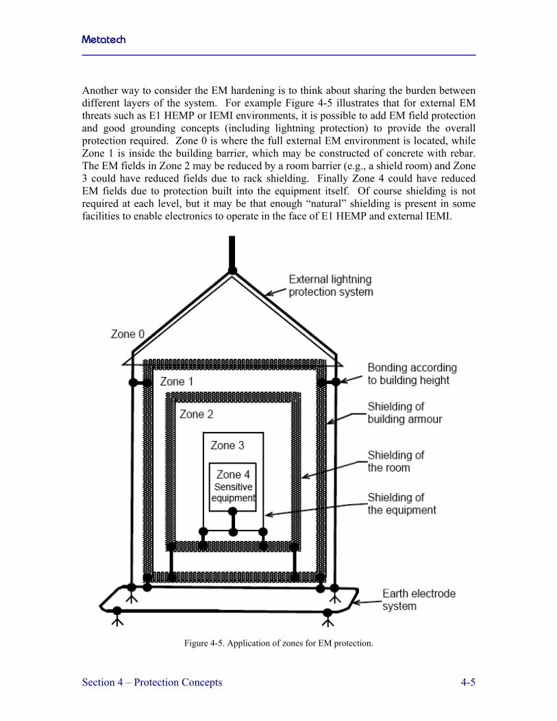
Another way to consider the EM hardening is to think about sharing the burden between different layers of the system. For example Figure 4-5 illustrates that for external EM threats such as E1 HEMP or IEMI environments, it is possible to add EM field protection and good grounding concepts (including lightning protection) to provide the overall protection required. Zone 0 is where the full external EM environment is located, while Zone 1 is inside the building barrier, which may be constructed of concrete with rebar. The EM fields in Zone 2 may be reduced by a room barrier (e.g., a shield room) and Zone 3 could have reduced fields due to rack shielding. Finally Zone 4 could have reduced EM fields due to protection built into the equipment itself. Of course shielding is not required at each level, but it may be that enough “natural” shielding is present in some facilities to enable electronics to operate in the face of E1 HEMP and external IEMI.
Figure 4-5. Application of zones for EM protection.

Metatech
Section 4 – Protection Concepts 4-6
In order to provide EM shielding at the room level, there are many companies that make shield rooms for applications varying from shielding hospitals from the effects of MRI machines to providing quiet rooms for performing EMC emission and immunity tests. Our application is to protect the electronics inside from the threats of E1 HEMP, IEMI and other EM environments (military radars nearby, radio transmitters, etc.). As indicated in Figure 4-6, in addition to metallic shield materials, it is important to provide protection to all cables entering and leaving the shield room. This includes power and communications. Protection for these lines can be done applying different techniques, depending on the relationship between the frequencies of the wanted signals to the unwanted signals.
Figure 4-6. Engineering design of EM shielding and conductor protection.
Another important issue is to properly deal with cables that are located within one of the EM zones of a building or room. One recommendation is to use non-metallic fiber optic cables to eliminate the EM coupling to the cables, but other approaches such as cable segregation, separation and proper routing can reduce the threat of high-frequency EM field coupling and impacts on cables and the equipment connected to them (Figure 4-7).

Metatech
Section 4 – Protection Concepts 4-7
Figure 4-7. Management of cables to reduce the impact of high-frequency EM coupling.
One example of a room hardening approach is shown in Figure 4-8. In this case a shielded room is constructed where all of the critical electronics is located. Air flow is provided through the use of a mesh-covered waveguide beyond cutoff to ensure that EM fields cannot penetrate the room. The external conductor shown could be a metallic cable data line that requires a filter or surge arrester at the entry point to the shield room. Any out of band or high-level E1 HEMP or IEMI currents would be shunted to the outer surface of the shield and will then flow to ground. If another nearby shielded area has the need for a connection to the equipment inside the shielded room, then shielded cables or a shield conduit could be used to connect the two shielded areas. These methods have been used by the U.S. military for many years, especially in MIL-STD-188-125-1, which defines the protection of time-urgent C4I systems to the threat of HEMP.

Metatech
Section 4 – Protection Concepts 4-8
Figure 4-8. Example of high-frequency EM mitigation application.
In all cases where EM shields are built, it is necessary to evaluate whether the shields have been constructed properly. The main way of checking shielding is through EM test methods, including the well-known low-level continuous wave test technique. This involves sweeping through a range of frequencies and measuring the fields outside the shielded facility and the fields or currents inside the facility. Figure 4-9 illustrates a typical setup for this type of test.
Shielded Facility
PowerAmplifier
Balun
ResistivelyLoadedWire
Dielectric Pole
Current Probe
Network Analyzer andMeasurement Equipment
ReferenceField Sensor
Internal Cable
CW Radiating Antenna
Figure 4-9. Setup to perform low level cw shielding test.

Metatech
Section 4 – Protection Concepts 4-9
4.3 Security Aspects of IEMI Mitigation While most of the focus of mitigation of high-frequency EM threats has been on hardening, the nature of IEMI is such that security measures can also be useful to reduce the impact of IEMI on critical electronics. Several recommendations that have value by keeping EM weapons away from sensitive electronics are listed below:
• Develop a “keep out” or buffer zone around your building • Prevent unauthorized access to all power and communications cables entering the
building • Keep important internal electronics equipment away from the outer walls of the
building • Prevent IEMI emitters from being placed near sensitive electronic systems • Monitor the EM environment near critical electronic systems.
These recommendations are aimed at reducing the level of any IEMI environment at the location of sensitive equipment and/or to detect an attack that may be underway. A combination of a security approach and an EM hardening approach should be considered for the threat of IEMI. 4.4 IEC SC 77C Standards In 1992, IEC Subcommittee 77C began to develop standards to protect commercial facilities and the infrastructure from the effects of the high-altitude electromagnetic pulse (HEMP). In 1999 this work was expanded to include all man-made high-power EM environments, including IEMI; the title of SC 77C was changed to: EMC-High Power Transients. The threat of IEMI has increased in recent years due to the increased sophistication of electronic equipment, the reliance of society on this equipment, and finally on the availability of electromagnetic weapons due to the development of high voltage generators of small size. Over the 18 years since the start of work in IEC SC 77C, 20 publications dealing with the threats and protection measures have been published. The publications dealing with HEMP and IEMI are fully integrated into the Electromagnetic Compatibility (EMC) publication system of the International Electrotechnical Commission. These publications cover topic areas of general interest, the EM environment, testing and measuring techniques, installation and mitigation guidelines and generic standards. The list of publications produced by IEC SC 77C is the most extensive of its kind dealing with HEMP and IEMI for commercial equipment and systems and is provided in Figure 4-10. Note that three publications are identified in a red font to indicate that they were just completed in 2009.

Metatech
Section 4 – Protection Concepts 4-10
61000-1-(General)
61000-2-(EMEnvironment)
61000-4-(Testing andMeasuringTechniques)
61000-5-(Installationand MitigationGuidelines)
61000-6-(Generic Standards)
-33HPEM
MEASUREMENTMETHODS
-3 HEMP EFFECTS ON SYSTEMS -5 HPEM EFFECTS ON SYSTEMS
-9 HEMPRADIATED
ENVIRONMENT
-10 HEMPCONDUCTED
ENVIRONMENT
-11CLASSIFICATION
OF HEMPENVIRONMENTS
-13HPEM
ENVIRONMENTS
-24TEST
METHODSCONDUCTED
-23TEST
METHODSRADIATED
-32HEMP
SIMULATORCOMPENDIUM
-25HEMP
IMMUNITYTESTS
-5 SPECIFICATIONSFOR CONDUCTED
PROTECTION
-7 EM CODE
-3 HEMPPROTECTIONCONCEPTS
-6 GENERICSTANDARD FOR HEMP
IMMUNITY
-6 MITIGATIONOF
EXTERNAL EMINFLUENCES
-4 SPECIFICATIONSFOR RADIATEDPROTECTION
-8 HEMP protectionmethods for thedistributed civilinfrastructure
-9 System-levelsusceptibility
assessments forHEMP and HPEM
-35 High Power EMSimulator Compendium
Figure 4-10. List of publications for IEC SC 77C dealing with HEMP and IEMI on civil systems.

Metatech
Section 5 – Protection Applications 5-1
Section 5 Protection Applications
5.1 HEMP Protection Applications This section takes the impacts to the power system described in Section 2 and indicates in general how the protection concepts discussed in Section 4 can be applied. 5.1.1 High Voltage Substation Controls and Communications The control building contains critical electronic equipment, such as safety relays, for ensuring the proper operation of a substation. These buildings and the cables that run from these buildings to the sensors and circuit breakers in the high voltage yard are ideal for applying standard high frequency shielding and cable protection technologies. The major effort suggested here is to determine the most cost effective means of providing this protection against E1 HEMP. The ideal approach is to perform comprehensive laboratory tests with actual field cable and high voltage PTs and CTs to determine the coupling and propagation characteristics of the cables and to determine the withstand levels of the sensors and circuit breakers. In addition, tests should be performed to determine cost effective ways of improving the high frequency grounding characteristics at the j-boxes inside of the control buildings. A third series of laboratory tests will involve the coupling to internal cabling types typically found inside of control buildings and how they penetrate racks. Examinations of improved grounding of these cables will be examined. Also techniques involving ferrites will be examined for common mode signals. After the laboratory tests are completed, the leading techniques will be applied at an actual high voltage substation control house to determine the practicality of the protection methods and to establish the costs of installation. In addition, the shielding effectiveness of different types of actual control house construction will be evaluated to develop an understanding of the amount of attenuation that would occur in the EM spectrum as a function of the building wall construction. Given the susceptibility data for relays, PLCs and RTUs, it will be possible to determine the amount of protection required and achieved at the end of this process. It will then be possible to develop standards through the IEEE or the IEC to ensure that the best hardening approaches will be used in the future. 5.1.2 Power Generation Facilities Power generation facilities are very similar to high-voltage substations except that these facilities are manned, providing the ability to deal with malfunctions on a more rapid basis. They also will have additional types of electronics that are similar to industrial

Metatech
Section 5 – Protection Applications 5-2
controls. These controls may well be more sensitive to high-frequency transients such as E1 HEMP or IEMI than the electronics in a high voltage substation. In order to evaluate this category of facility, it is recommended that several specific types of generation plants (nuclear, coal, natural gas, etc.) be evaluated in terms of the coupling of E1 HEMP into aboveground and buried control cables, with major attention given to the generator control centers. This will enable more realistic evaluation of the E1 HEMP voltages and currents expected at electronics controlling the power generation processes. When the analyses are completed, standard high-frequency protection methods will be evaluated in the laboratory to determine which methods are most cost effective for application to an actual generation facility. This would be done after the analysis and laboratory work is completed. The final stage of work will involve the writing of protection standards for the IEEE or IEC. 5.1.3 Power Control Centers Power control centers are considerably different than locations containing high voltage transformers and controls. In the control centers, PCs are used to monitor, control and communicate with the substations and power generators that control the operation of the grid. These facilities resemble computer centers with networked PCs and real time displays. The major concerns for these centers include the coupling of significant E1 HEMP transients on power and communications cables entering the facility from the outside. In addition, attention must be directed to the penetration of E1 HEMP fields into the control center itself. Based on the design and geometry of typical control centers, a program of measurement of shielding effectiveness should be done. In addition, the geometry of cables with power and communications entering the facilities should be analyzed. After this information is obtained, assessments of the vulnerability and the need for hardening will be completed. It is expected that because of the significant variations in the types of control centers, the output of this effort will be a set of guidelines on how to assess and improve the EM protection of power control centers. 5.1.4 Distribution Line Insulators For the threat of E1 HEMP on distribution line insulators, there is additional research required before the final approach for protection can be considered. First it is necessary to obtain statistical test data on the flashover and damage of U.S. power line insulators for E1-like voltage pulses while the insulators are powered by a typical supply voltage and current. The data obtained from the Russian testing is interesting, but may not be relevant to the vast majority of insulators in place in the U.S. at this time.

Metatech
Section 5 – Protection Applications 5-3
The lead option for protection of these distribution insulators is the placement of line-to-ground lightning surge arresters within 1 mile of the substation to ensure that the fault currents sensed at the substation are small enough to avoid tripping. In order for this protection approach to be effective, it will be necessary to test the efficiency of typical 100 kV BIL arresters for E1 HEMP voltage waveforms. If the power-on insulator testing illustrates a damage issue and the surge arrester testing provides a reasonable expectation that the arresters will work properly under E1 HEMP waveforms, then this protection scheme will be evaluated in more detail through HEMP analyses and costing. When completed, a hardening guideline document will be produced. 5.1.5 Distribution Transformers Based on the E1 HEMP injection testing done by Oak Ridge in the 1980s, the main issue regarding the vulnerability of distribution transformers is whether lightning protection was present. In addition an issue had been raised concerning the mounting of the lightning protection and whether the effectiveness of the lightning surge protectors for E1 HEMP would be impacted by the mounting procedure. A laboratory test program is recommended to examine the effectiveness of standard distribution transformer lightning surge arresters against E1 HEMP waveforms. This testing should also examine whether there are any issues involved in the mounting methods for lightning that could affect the protection afforded to E1 HEMP. Any conclusions from this testing should be documented in the form of guidelines for the power industry. 5.2 IEMI Protection Applications 5.2.1 High Voltage Substation Controls and Communications A similar approach for IEMI to that recommended for E1 HEMP would be followed except that there would be less emphasis on the cables in the high voltage yard and more emphasis on the EM field penetration through the walls of the substation control building. This additional data can be obtained by extending the frequency range of transfer function measurements to above 1 GHZ. Also, additional effort on grounding of cables at the j-box and at equipment racks will be necessary at the higher frequencies. After the laboratory tests are completed, the leading protection techniques will be applied at an actual high voltage substation control house to determine the practicality of the protection methods and to establish the costs of installation. In addition, the shielding effectiveness of different types of actual control house construction will be evaluated to develop an understanding of the amount of attenuation that would occur in the EM spectrum as a function of the building wall construction. For IEMI we would examine detector technologies and costs to see if monitors would be effective for the unmanned substations.

Metatech
Section 5 – Protection Applications 5-4
The final stage of work will involve the writing of protection standards for the IEEE or IEC. 5.2.2 Power Generation Facilities Power generation facilities are very similar to high-voltage substations except that these facilities are manned, providing the ability to deal with malfunctions on a more rapid basis. The IEMI approach would be similar to that for E1 HEMP, especially in terms of evaluating the penetration of EM fields into the generator control room, except at frequencies above 1 GHz. When the analyses are completed, standard high-frequency protection methods will be evaluated in the laboratory to determine which methods are most cost effective for application to an actual generation facility. This would be done after the analysis and laboratory work is completed. The final stage of work will involve the writing of protection standards for the IEEE or IEC. 5.2.3 Power Control Centers Power control centers are considerably different than locations containing high voltage transformers and controls. In the control centers, PCs are used to monitor, control and communicate with the substations and power generators that control the operation of the grid. These facilities resemble computer centers with networked PCs and real time displays. For IEMI, attention must be directed to the penetration of IEMI fields into the control center itself. Based on the design and geometry of typical control centers, a program of measurement of shielding effectiveness should be done. This can be done at the same time the measurements are performed for E1 HEMP, but in this case for frequencies above 1 GHz. After this information is obtained, assessments of the vulnerability and the need for hardening will be completed. It is expected that because of the significant variations in the types of control centers, the output of this effort will be a set of guidelines on how to assess and improve the EM protection of power control centers. 5.2.4 Distribution Line Insulators For distribution line insulators there is no real issue for IEMI since it is nearly impossible to couple voltages greater than 100 kV on an elevated power line. 5.2.5 Distribution Transformers For distribution transformers mounted on power poles, it is impossible to couple IEMI voltages greater than 100 kV, and the failure levels appear to be in the range of 300 kV.

Metatech
Bibliography B-1
Bibliography
Technical Reports and Papers
Air Force Weapons Laboratory, “EMP Interaction: Principles, Techniques, and Reference Data”, AFWL-TR-80-402 (EMP Interaction 2-1), Dikewood Industries, Inc., December 1980.
Glasstone, Samuel, and Philip J. Dolan, The Effects of Nuclear Weapons, U.S. Departments of Defense and Energy, 1977 (1st edition: 1957, 2nd edition 1962).
Grzybowski, Dr. S., and Yang Song, “Investigation on the Electrical Strength of the Distribution Line Elements Under Steep Front, Short Duration Pulses”, Mississippi State University, January 2004.
Longmire, C.L., “On the Electromagnetic Pulse Produced by Nuclear Explosions”, IEEE Trans. Ant. & Prop., Vol. AP-26, No. 1, January 1978.
MIL-HDBK-423, “High-Altitude Electromagnetic Pulse (HEMP) Protection for Fixed and Transportable Ground-Based Facilities, Volume I Fixed Facilities”, 15 May 1993.
MIL-STD-188-125-1, “Department of Defense Interface Standard. High-Altitude Electromagnetic Pulse (HEMP) Protection for Ground-Based C4I Facilities Performing Critical, Time-Urgent Missions, Part 1 Fixed Facilities”, 17 July 1998.
Northrop, John, Handbook of Nuclear Weapon Effects, Calculational Tools Abstracted from DSWA’s Effects Manual One (EM-1), Defense Threat Reduction Agency, September, 1996 (limited distribution).
Parfenov, Y., “Research of Physical Laws of the Flashover and Damage of Power Line Insulators due to Fast Voltage Pulses with Power On and Power Off is Important Problem”, Institute for High Energy Densities, January 25, 2004.
Radasky, W. A. and R. L. Knight, “HAPS — A Two Dimensional High Altitude EMP Environment Code”, Air Force Weapons Laboratory, EMP TN 125, November 1971.
Radasky, W. A., W. J. Karzas, G. K. Schlegel and C. W. Jones, “High Altitude Electromagnetic Pulse — Theory and Calculations”, Defense Nuclear Agency, DNA TR 88 123, 3 October 1988.
Radasky, W. A., “High-altitude EMP (HEMP) Environments and Effects”, NBC Report, Spring/Summer 2002, pp. 24-29.
Radasky, W. A., “High-Altitude Electromagnetic Pulse (HEMP): A Threat to Our Way of Life”, IEEE USA Today’s Engineer, September 2007.
Radasky, W., “Approach for Protection of HV Power Grid Network Control Electronics from Intentional Electromagnetic Interference (IEMI)”, CIGRE SC C4 2009 Kushiro Colloquium, June 2009.

Metatech
Bibliography B-2
Schaefer, R.R., F.C. Dumont, and C.R. Grain, “High-Altitude Electromagnetic Pulse (HEMP) Hardness Maintenance/Hardness Surveillance for Fixed, Ground-Based C4I Facilities, Volumes 1-3”, DNA-TR-93-186-V1 through V3, April 1995.
Sherman, R., et al., EMP Engineering and Design Principles, Bell Telephone Laboratories Report, 1975.
IEC References
IEC, “Electromagnetic compatibility (EMC) - Part 1-3: General - The effects of high-altitude EMP (HEMP) on civil equipment and systems”, IEC 61000-1-3, International Electrotechnical Commission, Geneva, Switzerland
IEC, “Electromagnetic compatibility (EMC) - Part 1-5: General - High power electromagnetic (HPEM) effects on civil systems”, IEC 61000-1-5, International Electrotechnical Commission, Geneva, Switzerland
IEC, “Electromagnetic compatibility (EMC) - Part 2: Environment - Section 3: Description of the environment - Radiated and non-network-frequency-related conducted phenomena”, IEC 61000-2-3, International Electrotechnical Commission, Geneva, Switzerland
IEC, “Electromagnetic compatibility (EMC) - Part 2: Environment - Section 5: Classification of electromagnetic environments. Basic EMC publication”, IEC 61000-2-5, International Electrotechnical Commission, Geneva, Switzerland
IEC, “Electromagnetic compatibility (EMC) - Part 2: Environment - Section 9: Description of HEMP environment - Radiated disturbance. Basic EMC publication”, IEC 61000-2-9, International Electrotechnical Commission, Geneva, Switzerland
IEC, “Electromagnetic compatibility (EMC) - Part 2-10: Environment - Description of HEMP environment - Conducted disturbance”, IEC 61000-2-10, International Electrotechnical Commission, Geneva, Switzerland
IEC, “Electromagnetic compatibility (EMC) - Part 2-11: Environment - Classification of HEMP environments”, IEC 61000-2-11, International Electrotechnical Commission, Geneva, Switzerland
IEC, “Electromagnetic compatibility (EMC) - Part 2-13: Environment - High-power electromagnetic (HPEM) environments - Radiated and conducted”, IEC 61000-2-13, International Electrotechnical Commission, Geneva, Switzerland
IEC, “Electromagnetic compatibility (EMC) - Part 4-1: Testing and measurement techniques - Overview of IEC 61000-4 series”, IEC 61000-4-1, International Electrotechnical Commission, Geneva, Switzerland
IEC, “Electromagnetic compatibility (EMC)- Part 4-2: Testing and measurement techniques - Electrostatic discharge immunity test”, IEC 61000-4-2, International Electrotechnical Commission, Geneva, Switzerland

Metatech
Bibliography B-3
IEC, “Electromagnetic compatibility (EMC) - Part 4-3 : Testing and measurement techniques - Radiated, radio-frequency, electromagnetic field immunity test”, IEC 61000-4-3, International Electrotechnical Commission, Geneva, Switzerland
IEC, “Electromagnetic compatibility (EMC) - Part 4-4: Testing and measurement techniques - Electrical fast transient/burst immunity test”, IEC 61000-4-4, International Electrotechnical Commission, Geneva, Switzerland
IEC, “Electromagnetic compatibility (EMC) - Part 4-5: Testing and measurement techniques - Surge immunity test”, IEC 61000-4-5, International Electrotechnical Commission, Geneva, Switzerland
IEC, “Electromagnetic compatibility (EMC) - Part 4-6: Testing and measurement techniques - Immunity to conducted disturbances, induced by radio-frequency fields”, IEC 61000-4-6, International Electrotechnical Commission, Geneva, Switzerland
IEC, “Electromagnetic compatibility (EMC) - Part 4-12: Testing and measurement techniques - Ring wave immunity test”, IEC 61000-4-12, International Electrotechnical Commission, Geneva, Switzerland
IEC, “Electromagnetic compatibility (EMC) - Part 4-18: Testing and measurement techniques - Damped oscillatory wave immunity test”, IEC 61000-4-18, International Electrotechnical Commission, Geneva, Switzerland
IEC, “Electromagnetic compatibility (EMC) - Part 4-20: Testing and measurement techniques - Emission and immunity testing in transverse electromagnetic (TEM) waveguides”, IEC 61000-4-20, International Electrotechnical Commission, Geneva, Switzerland
IEC, “Electromagnetic compatibility (EMC) - Part 4-21: Testing and measurement techniques - Reverberation chamber test methods”, IEC 61000-4-21, International Electrotechnical Commission, Geneva, Switzerland
IEC, “Electromagnetic compatibility (EMC) - Part 4-23: Testing and measurement techniques - Test methods for protective devices for HEMP and other radiated disturbances”, IEC 61000-4-23, International Electrotechnical Commission, Geneva, Switzerland
IEC, “Electromagnetic compatibility (EMC) - Part 4-24: Testing and measurement techniques - Section 24: Test methods for protective devices for HEMP conducted disturbance - Basic EMC Publication”, IEC 61000-4-24, International Electrotechnical Commission, Geneva, Switzerland
IEC, “Electromagnetic compatibility (EMC) - Part 4-25: Testing and measurement techniques - HEMP immunity test methods for equipment and systems”, IEC 61000-4-25, International Electrotechnical Commission, Geneva, Switzerland
IEC, “Electromagnetic compatibility (EMC) - Part 4-32: Testing and measurement techniques - High-altitude electromagnetic pulse (HEMP) simulator compendium”, IEC 61000-4-32, International Electrotechnical Commission, Geneva, Switzerland

Metatech
Bibliography B-4
IEC, “Electromagnetic compatibility (EMC) - Part 4-33: Testing and measurement techniques - Measurement methods for high-power transient parameters”, IEC 61000-4-33, International Electrotechnical Commission, Geneva, Switzerland
IEC, “Electromagnetic compatibility (EMC) - Part 4-35: Testing and measurement techniques - HPEM simulator compendium”, IEC 61000-4-35, International Electrotechnical Commission, Geneva, Switzerland
IEC, “Electromagnetic compatibility (EMC) - Part 5: Installation and mitigation guidelines - Section 1: General considerations - Basic EMC publication”, IEC 61000-5-1, International Electrotechnical Commission, Geneva, Switzerland
IEC, “Electromagnetic compatibility (EMC) - Part 5: Installation and mitigation guidelines - Section 2: Earthing and cabling”, IEC 61000-5-2, International Electrotechnical Commission, Geneva, Switzerland
IEC, “Electromagnetic compatibility (EMC) - Part 5-3: Installation and mitigation guidelines - HEMP protection concepts”, IEC 61000-5-3, International Electrotechnical Commission, Geneva, Switzerland
IEC, “Electromagnetic compatibility (EMC) - Part 5: Installation and mitigation guidelines - Section 4: Immunity to HEMP - Specifications for protective devices against HEMP radiated disturbance. Basic EMC Publication”, IEC 61000-5-4, International Electrotechnical Commission, Geneva, Switzerland
IEC, “Electromagnetic compatibility (EMC) - Part 5: Installation and mitigation guidelines - Section 5: Specification of protective devices for HEMP conducted disturbance. Basic EMC Publication”, IEC 61000-5-5, International Electrotechnical Commission, Geneva, Switzerland
IEC, “Electromagnetic compatibility (EMC) - Part 5-6: Installation and mitigation guidelines - Mitigation of external EM influences”, IEC 61000-5-6, International Electrotechnical Commission, Geneva, Switzerland
IEC, “Electromagnetic compatibility (EMC) - Part 5-7: Installation and mitigation guidelines - Degrees of protection provided by enclosures against electromagnetic disturbances (EM code)”, IEC 61000-5-7, International Electrotechnical Commission, Geneva, Switzerland
IEC, “Electromagnetic compatibility (EMC) - Part 5-8: Installation and mitigation guidelines - HEMP protection methods for the distributed infrastructure”, IEC 61000-5-8, International Electrotechnical Commission, Geneva, Switzerland
IEC, “Electromagnetic compatibility (EMC) - Part 5-9: Installation and mitigation guidelines - System-level susceptibility assessments for HEMP and HPEM”, IEC 61000-5-9, International Electrotechnical Commission, Geneva, Switzerland
IEC, “Electromagnetic compatibility (EMC) - Part 6-1: Generic standards - Immunity for residential, commercial and light-industrial environments”, IEC 61000-6-1, International Electrotechnical Commission, Geneva, Switzerland

Metatech
Bibliography B-5
IEC, “Electromagnetic compatibility (EMC) - Part 6-2: Generic standards - Immunity for industrial environments”, IEC 61000-6-2, International Electrotechnical Commission, Geneva, Switzerland
IEC, “Electromagnetic compatibility (EMC) - Part 6-5: Generic standards - Immunity for power station and substation environments”, IEC 61000-6-5, International Electrotechnical Commission, Geneva, Switzerland
IEC, “Electromagnetic compatibility (EMC) - Part 6-6: Generic standards - HEMP immunity for indoor equipment”, IEC 61000-6-6, International Electrotechnical Commission, Geneva, Switzerland