high idle kit - carid.com · pdf filethis high idle kit connects to the vehicle throttle pedal...
TRANSCRIPT

1
HIGH IDLE KIT
1036620 1998.5 – 2002 Dodge Cummins (24 valve) 2003-2004 Dodge Cummins (with APPS on motor)
1036621 2005-2006 Dodge Cummins
1036622 2007-2017 Dodge Cummins / 2014-2017 Dodge 3.0L Eco Diesel
1036627 2008- 2017 GMC Duramax U

2
K I T C O N T E N T S :Please check to make sure that you have all the parts listed in this kit before you start
the disassembly of your vehicle. 1036620 High Idle Kit
1301185 1331190-3 1003331
High idle Module Wiring Harness High Idle Decal
Qty: 1 Qty: 1 Qty: 1
1330050 1330052 1300348 1330054 1330053 1300131
Switch Bracket Screw Posi-tap Tape; DS Alcohol Swab Cable Tie
Qty: 1 Qty: 2 Qty: 1 Qty: 1 Qty: 1 Qty: 6

3
1036621 High Idle Kit
1301185 1331191-3 1003331
High idle Module Wiring Harness High Idle Decal
Qty: 1 Qty: 1 Qty: 1
1330050 1330052 1300348 1330054 1330053 1300131
Switch Bracket Screw Posi-tap Tape; DS Alcohol Swab Cable Tie
Qty: 1 Qty: 2 Qty: 1 Qty: 1 Qty: 1 Qty: 6

4
1036622 High Idle Kit
1301185 1331192-3 1003331
High idle Module Wiring Harness High Idle Decal
Qty: 1 Qty: 1 Qty: 1
1330050 1330052 1300348 1330054 1330053 1300131
Switch Bracket Screw Posi-tap Tape; DS Alcohol Swab Cable Tie
Qty: 1 Qty: 2 Qty: 1 Qty: 1 Qty: 1 Qty: 6

5
1036627 High Idle Kit
1301185 1331197-3 1003331
High idle Module Wiring Harness High Idle Decal
Qty: 1 Qty: 1 Qty: 1
1330050 1330052 1300348 1330054 1330053 1300131
Switch Bracket Screw Posi-tap Tape; DS Alcohol Swab Cable Tie
Qty: 1 Qty: 2 Qty: 1 Qty: 1 Qty: 1 Qty: 6

6 Tools Required
Wire Strippers Side Cutters Utility Knife
Flat Screwdriver Philips Screwdriver Soldering Equipment
Introduction
This high idle kit connects to the vehicle throttle pedal and allows the operator to increase engine speed easily by way of a control knob mounted on the dashboard. This kit is ideal for faster engine warm-ups, extended idling, running belt driven power take off equipment and high power electrical accessories including winches, inverters and pumps.
Closed loop control provides up to five engine speeds: 900, 1200, 1500, 1800, 2100 rpm.
Note: This kit does not control the transmission torque converter as is required for many forms of automatic transmission mounted power take-off equipment. This kit will work with manual transmission mounted PTO applications.
NOTE: Some 1998-2002 Dodge trucks, the 2100RPM setting will set a fault code for MAP vs. throttle correlation. This is due to a problem with the ECU calibration from Chrysler. If this problem arises, change the switch keying to disallow the 2100RPM setting.
INSTALLATION
VEHICLE SHOULD BE SAFELY SECURED BEFORE INSTALLATION.
1. To avoid setting possible fault codes, disconnect vehicle batteries before proceeding.
2. Locate vehicle accelerator pedal position sensor and disconnect the wiring harness.a. On 1998.5-2004 Dodge vehicles, this sensor is located under a plastic cover
below the intake elbow on the driver’s side of the engine. The sensorsconnector faces downward.

7
b. On all other models, the sensor is built into the top of the accelerator pedalbelow the dashboard.

8
3. Connect supplied wiring harness to the accelerator pedal position sensor and theother end to the factory wiring harness. Secure harness with zip ties so that it does notinterfere with pedal operation. Removal of the knee bolster may ease installation.
4. For 98.5-04 Dodge kits, disconnect the control knob harness from the main wiringharness. Route the small disconnect wire through the firewall and reconnect it to themain wiring harness. (Not required on other models).
For all applications other than the 98.5-04 Dodge kits, route the light blue wire (RPM signal) from below the dash into the engine bay through the firewall. 5. Connect the white brake light input wire to the brake light switch using supplied
positap. This connection may be soldered for better longevity if desired.
WHITE wire (brake light 12V) Location to tap 1998-2001 Dodge Pin 5 - White/Tan Brake Switch 2002-2009 Dodge Pin 2 – White/Tan Brake Switch 2010-2012 Dodge Pin 2 – White Brake Switch 2013-2017 Dodge Connector C5/E
Pin 31 – White/Violet Body Control Module
2014-2017 Dodge 3.0L (EcoDiesel)
Connector C6/F, Pin 39 White/Dark Green Body Control Module
2001-2007 GMC Pin A – White Brake Switch 2007.5-2011 GMC Pin A – Lt Blue/White Brake Switch 2012-2014 GMC Connector 5, Pin 5 – Lt Blue Body Control Module 2015-2017 GMC Connector 4, Pin 11 – Violet/White Body Control Module

9
Brake lamp switch – 1998-2009 Dodge The brake lamp switch is located on the brake pedal assembly under the dash.
1998-2001 (PIN 5 WH/TN) Brake lamp switch output 2002-2009 (PIN 2 WH/TN) Brake lamp switch output
Brake lamp switch - 2010-2012 Dodge The brake lamp switch is located on the brake pedal assembly under the dash.
(PIN 2 WT) Brake lamp switch output
Body Control Module – 2013-2017 Dodge The body control module is located on the firewall on the inside of the truck behind the dash on the driver’s side. 2013-2017 (PIN 31 WH/VT) Brake lamp switch output (connector C5/E) 2014-2017 (PIN 39 WH/DG) Ecodiesel - Brake lamp switch output (connector C6/F)

10
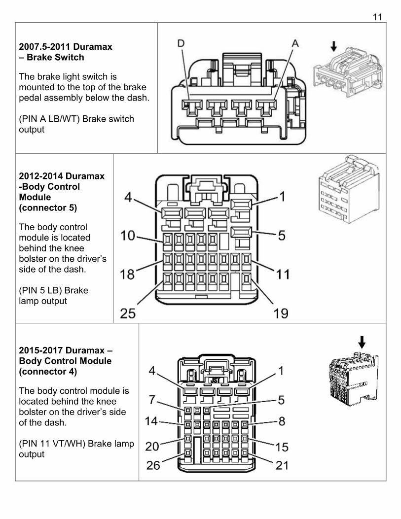
11
2007.5-2011 Duramax – Brake Switch
The brake light switch is mounted to the top of the brake pedal assembly below the dash.
(PIN A LB/WT) Brake switch output
2012-2014 Duramax -Body ControlModule(connector 5)
The body control module is located behind the knee bolster on the driver’s side of the dash.
(PIN 5 LB) Brake lamp output
2015-2017 Duramax – Body Control Module (connector 4)
The body control module is located behind the knee bolster on the driver’s side of the dash.
(PIN 11 VT/WH) Brake lamp output

12 6. Connect the light blue wire from the module onto the crankshaft or camshaft sensor
signal wire as indicated below. A positap has not been supplied for this connection asit is to be soldered.
Signal Wire RPM signal wire and suggested tap location
1998.5-2000 Dodge Camshaft Plug in connector supplied for cam position sensor
2001-2002 Dodge Camshaft Plug in connector supplied for cam position sensor
2003 Dodge Crankshaft White with Tan tracer Crank sensor pin 3
2004 Dodge Crankshaft Light Blue with Brown tracer -or- Brown with Light Blue tracer Crank sensor pin 3
2005-2017 Dodge Crankshaft Brown with Light Blue tracer Crank sensor pin 3
2014-2017 Dodge 3.0 (EcoDiesel)
Crankshaft Brown with light Blue tracer. Crank sensor pin 3
2008-2010 GM (LMM)
Crankshaft White with Black tracer Pin 17 – 40 way black main engine disconnect.
2011-2016 GM (LML)
Crankshaft White with Black tracer In orange loomed engine wire harness
2017 GM (L5P) Crankshaft Green wire Pin 3 of the 8 pin harness connector on top of engine.

13 1998-2002 Dodge 5.9 (24V) – Locate the engine camshaft position (CMP) sensor, just above the injection pump on the back side of the engine timing cover. Disconnect the camshaft position sensor connector and plug in the supplied connector in line with the sensor.
2003-2004 Dodge 5.9L (CR) – Locate the engine crankshaft position sensor, located toward the front of the engine on the left side beside the harmonic balancer. Cut off and discard the supplied three pin connector from the blue wire on the BD wiring harness (this is used only up to 2002). Tap the blue wire into the crankshaft sensor wire from pin 3 of the connector. Solder this connection and cover with heat shrink for longevity.
->2003 is a white wire with tan tracer ->2004 may be either light blue with brown tracer or brown with light blue tracer depending on build date.
2005-2017 Dodge 5.9/6.7L – Locate the engine crankshaft position sensor, located toward the front of the engine on the left side beside the harmonic balancer. Tap the brown wire with light blue tracer (connector pin 3). Solder this connection and cover with heat shrink for longevity.

14 2014-2017 Dodge 3.0L (EcoDiesel) - Locate the engine crankshaft position sensor connector. This is located in the rear of the engine oil pan, just ahead of the transmission as shown in the picture. Tap the brown wire with light blue tracer (connector pin 3). Solder this connection and cover with heat shrink for longevity.
2008-2010 GM LMM – Locate the 40 way black engine disconnect on top left of engine. Locate pin number 17 (white wire with black tracker). Tap blue wire from the module onto this wire. Solder this connection and cover with heat shrink for longevity.

15
2011-2016 GM LML – Locate the main engine wiring harness (orange color). Caution: other wires in this harness run up to 250 volts, use care not to damage other wires or tap the incorrect wire. Remove the harness tape from the orange loom. Locate the 20 gauge white wire with black tracer. Verify there are no duplicate wire colors in this harness as tapping into the incorrect wire may damage the module. Solder this connection and cover with heat shrink for longevity. Put wires back into orange loom and wrap loom with harness tape.
2017 GM L5P – Locate the 8 pin sub-harness disconnect on the top of the engine for the crankshaft position sensor. Locate the solid green wire in pin 3. Remove some harness tape to have some wire to work with. Attach the light blue wire here for RPM pickup. Solder the wire and cover with heat shrink for longevity. Rewrap with tape when complete.

16
7. By default, the control knob has six positions: off, 900, 1200, 1500, 1800 and 2100rpm. If a lower maximum rpm is desired, first turn the switch fully counter clockwise(off). Remove the knob and secondary mounting nut on the switch and lift out theswitch positioning ring. Reinstall the ring such that it reduces the number of switchpositions to the maximum rpm desired. Reassemble switch.
Check with the customer regarding what their needs are. If the high idle will be usedmainly for extended idling or faster warm-ups, it may be desirable to limit themaximum RPM.
NOTE: Some 1998-2002 Dodge trucks, the 2100RPM setting will set a fault code for MAP vs. throttle correlation. This is due to a problem with the ECU calibration from Chrysler. If this problem arises, change the switch keying to disallow the 2100RPM setting.
8. Install the control knob. If installing directly into the dashboard, drill a 1/4” hole for theswitch and a 1/16” hole for the locator tab. If using supplied bracket, install using thesupplied screws. Apply decal around the hole or the bracket and then install controlknob retainer nut. The knob requires a 1/16” Allen key to secure.
9. Remove coverfrom module.

17
10. For 1998.5-2000 Dodge 24V applications, setthe switch on the circuit board to position 3.
For 2001-2002 Dodge 24V applications, set the switch on the circuit board to position 2.
For all other applications leave switch in position 1.
11. Connect the module circuit board to the wiring harness with the cover still off andkeep away from metal objects that could cause a short circuit.
12. Reconnect vehicle batteries.
13. Before turning the ignition switch on make sure the high idle control switch is turnedoff or fault codes may be set.
Turn ignition switch to on position (not run) and then press and release the “LEARN PEDAL” button on the module. The READY and ACTIVE indicator lights will both illuminate. Slowly depress and release the throttle pedal a few times within 15 seconds. This will allow the module to learn you specific accelerator pedal sensor output. Make sure the pedal travel is not impeded by a floor mat. Once complete, the ACTIVE light will turn back off and the READY light should go back to flashing.
Note. If the pedal is replaced, it is a good idea to learn the module again.
14. Snap cover back on module and mount the module below the dashboard or in theengine bay for 1998.5-2004 Dodge trucks.
15. Check for correct operation. Ensure that pressing the brake pedal does stop highidle correctly. Installation is now complete.
2
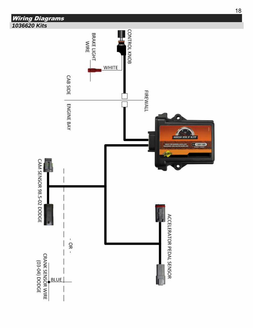
18 Wiring Diagrams
1036620 Kits
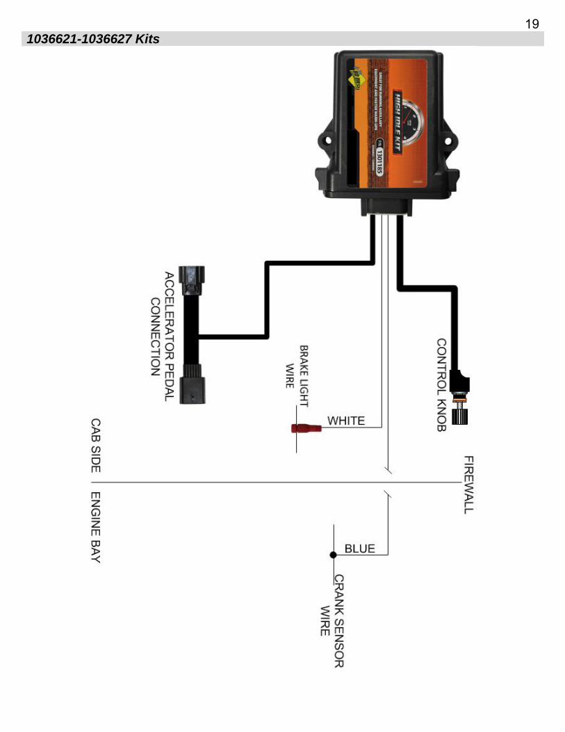
19 1036621-1036627 Kits

20
Operation Instructions
The high idle kit allows the operator to command the engine to idle up by rotating the control switch mounted on the dashboard. When the knob is fully counter counterclockwise, the module will not command high idle. Turning the knob clockwise will enable the module. The available engine RPMs are 900, 1200, 1500, 1800 and 2100 rpm.
If the brake is pressed or the throttle is pressed the module will stop high idle. If this happens, the switch must be turned off and then back on or to another position to re-enable high idle. If the engine is shut off and restarted, the module will be reactivated. This feature allows the user to leave the high idle module in the desired position so that it will start automatically when the engine is started.
If the module is already turned on when the truck is started, the module will wait for 5 seconds before starting high idle. This is to allow oil pressure to stabilize before increasing engine speed. If high idle is required immediately, turning the module off and back on will cancel the timer.
Note: Late model Duramax engines will not allow excessive engine speeds when remote started. For this reason, we recommend not exceeding 1500rpm for remote start warm-ups. This applies only to factory remote start, when the key is put in the ignition this restriction is removed. On these vehicles, exceeding approximately 2000 rpm when remote started will cause the engine to automatically shut off.

21 Troubleshooting
Vehicle Sets Codes for APPS Circuits
Check that the module is powered by removing the cover and checking for the POWER lamp. This should be lit whenever the ignition is on (and may remain powered after the ignition has been turned off for a short time on late model trucks).
Ensure the connectors are fully seated. Some connectors are harder to mate together than others, ensure they do not come apart if tugged on.
High Idle Does Not Function
Open the module and check that when the brake and throttle are not pressed and the engine is running, the READY lamp is illuminated and not flashing. This indicates that the modules safety inputs are working, the engine RPM is detected and the module is ready to operate when commanded. If the READY lamp is flashing, this indicates the brake and throttle are not pressed, but the engine is not running or has no RPM input signal. If the READY lamp is not illuminated, verify that the brake lights are not stuck on and throttle pedal is not stuck down. If the module has not been learned to the throttle pedal, the READY lamp may not illuminate.
Ensure that the ACTIVE light is on when the switch is turned on. If the ACTIVE light is flashing this indicates the control switch is commanding high idle, but the module is disabling it because it detected the brake or throttle was pressed or the engine is not running. If the ACTIVE light is on and not flashing, it should be ready to apply throttle to increase the idle speed.
The module must be learned to the throttle pedal for it to increase idle speed. If not setup correctly, refer to installation step 9 above.
Brake Pedal Does Not Cancel High Idle
Verify brake lights function. If nonfunctional, correct this first.
Verify the brake sense wire is tapped on the correct wire and use test light to verify that 12V is present on the white wire when the brake pedal is pressed.
Open module and observe READY light. This light should go out when the brake or throttle pedal are pressed.
Discover other fuel management on our website.