high kinetic processing of enamel, part i
TRANSCRIPT

Tel. No.: +49-2762-9756-0 Simo25-I-Paper.doc.DOC Fax No.: +49-2762-9756-7 Page 1
High Kinetic Processing of Enamel, part I cooperative project 09-8-4413
1H. Zoz, 1H.U.Benz, 2G. Schäfer, 3M. Dannehl, 4J. Krüll, 5F. Kaup, 1H. Ren, 1R. Reichardt
1Zoz GmbH, D-57482 Wenden, Germany 2Pfaudler Werke GmbH, D-68723 Schwetzingen, Germany
3Degussa-Hüls AG, D-63457 Hanau, Germany 4Wendel GmbH, D-35683 Dillenburg, Germany
5Miele & Cie. GmbH & Co., D-33332 Gütersloh, Germany
abstract Coatings of Enamels, Glass Fluxes and Glaze Frits are used in large quantities all over the world. The main application areas might be divided into household appliances, sign & signal (& arts), anti-corrosives and electronics. The conventional processing route of the rapidly quenched glass-material is mechanical grinding in a low kinetic (drum-) ball-mill down to fine solid particles in a liquid base (slurry). The present paper describes the application of High Energy Milling (HEM) which is usually used to perform Mechanical Alloying (MA), Reactive Milling (RM) as well as particle deformation and processing directly by HEM to produce nanocrystalline and amor-phous materials, ductile metal flakes and others. The reported preliminary testing has been performed in a lab-scale system (Simoloyer CM01-2l) in dry and batch-processing route. The results do show that the HEM-route leads to finer powder (average size about 5 µm) in a very short time (< 2 minutes). Based on the short processing time, a semi-continuously route has been considered to be applied. The initial testing in continuously operation by depression did lead to a particle-size D50-value of 6µm after a processing time of 20-40 seconds where the starting particle size was about 6 mm. Here the comparison leads to 3 times finer particles in a 500-600 times shorter process which will also be explained due to an insitu classification/separation. The even more prospective route, the semi-continuously operation mode by compression, where a carrier-gas-system is fed outside the processing-chamber with starting material and cycled in a closed gas-system will be discussed here. Due to the tremendous decrease of processing time and it’s principle based on collision of grinding media, contamination by the milling tools might be controlled perfectly. Together with a high possibility of insitu adaptation of further follow-up processing steps, this dry and high kinetic processing route promises an increase of quality at a decrease of producing cost and an increase of product flexibility at the same time. Considering that the future target for the particle size distribution will become < 10 µm, probably at a narrower size distribution, this potential appears even more interesting. The characterization of materials has been done by scanning electron microscopy and particle size distribution measurement by laser diffraction, results of melting tests are discussed.
1. Introduction Coatings of Enamels, Glass Fluxes and Glaze Frits are used in large quantities all over the world. Applications cover equipment of everyday use up to high-tech products. Important advantages of enamel are the good physical and at the same time excellent chemical properties and the nice and shiny appearance of the material. An important commercial criteria is a safe and easy applica-tion as well as quite low cost. The present paper is a summary of Part I of the cooperative project 09-8-4413 of Zoz GmbH, Pfaudler Werke GmbH, Degussa-Hüls AG, Wendel GmbH and Miele & Cie. GmbH & Co. in Germany. The aim of this work is first to replace a common processing technique by a new, much faster processing route reaching the same product quality at much lower processing cost and much higher product flexibility. The second goal is to produce a different/better quality which means in case of the enamel a finer particle size than possible by the conventional route. Since Zoz is originally a manufacturer of simple low-kinetic milling devices (drum-ball-mills) which is the equipment that is worldwide commercially used for the here described conventional route and on the other hand a manufacturer and end-user of high-kinetic processing equipment, it has been quite obvious to explore the application of a high-kinetic processing route for what is done in a low-kinetic route since centuries. In fact some very initial and simple tests have been that promising, that the cooperative project with major enamel producers and applicators has been founded.

Simo25-I-Paper.doc Tel. No.: +49-2762-9756-0 Page 2 Fax No.: +49-2762-9756-7
heat treatment (substrate with l)
application by dipping, spraying, i i
sieving and magnetic-filter
grinding of slurry in low-kinetic milling drummills alumina-
Starting i lenamel, glass-
fHigh Energy Milling
batch, semi-continuous in depression and compression mode
Zoz GmbH
1. Initial testing in batch process finer powder, 150 times
2. Initial continuous testing 3 times finer powder, 500
3. Stable semi-continuous operation 3 times finer powder, 500
Pfaudler Werke GmbH Degussa-Hüls AG Wendel GmbH Miele & Cie. GmbH &
5 h d 15-20 50
Fig. 01: flow-chart of Cooperative Project 09-8-4413
2. State of the art of processing enamels and glass fluxes, applications
Enamels, Glass Fluxes and Glaze Frits seem to be simple isotropic materials since they just consist of metal-oxides and some other inorganic additives. In fact it starts to get very complicated when adjusting the melting temperatures, in particular very low tempera-tures, the adhesion behavior in particular on metal, the surface before and after application by varying the composition and surface treatment (coating) of the particles. The table in figure 02 shows that the melting temperature is a determining factor for potential applications since it e.g. limits the potential substrate-materials, application techniques etc.
Glass-fluxes, enamels and glass frits, melting temperatures and typical applications glass-fluxes lt enamels glass fluxes ht glass frits melting temperature < 400°C 400 – 800°C 800-1200°C 1200-1400°C general applications soldering
printing coating of
metal substrates coating of
ceramic substrates source & high temperature
function !"isolation !"adhesion !"optical appearance
!"optical appearance !"surface !"chemical isolation
!"electrical (& chemical) isolation
!"optical appearance !"surface
!"glassware !"optical appearance !"surface
application • electronics, EP • transmitters • screens LCD • screens automotive • top-coatings
• sanitation • electronics • chemical • sign & signal • glass-screens
• sanitation • tile- and tableware • sign & signal • insulators • varistors
• electronics • high voltage • insulators • varistors
Fig. 02: Glass-fluxes, enamels and glass frits, melting temperatures and typical applications
The base resources for the glass-materials are mostly natural like SiO2, SiO4, sometimes synthetic SiO2 for high performance appli-cations. The resource materials are usually cleaned, washed, sometimes crushed or ground and then mixed with additives like B2O3, Al2O3 or TiO2 into a turn-tube-furnace and melted. The liquid glass base material is then rapidly quenched either into a wa-ter-flow or onto a cooling roll (figure 03). By this process, irregular (water-flow) or flake-shaped (cooling roll) frits are received in the size between 1 - 10 mm (figure 04).

Tel. No.: +49-2762-9756-0 Simo25-I-Paper.doc.DOC Fax No.: +49-2762-9756-7 Page 3
Fig. 03: unloading of a turn-tube-furnace into water-flow (left) and onto cooling roll (right) Fig. 04: irregular frits rapidly quenched into water-flow
(top) and onto cooling roll (bottom)
The next processing step is the particle size reduction of the rapidly quenched frits which is of the main interest in the present paper. The major applied conventional route here is described by a milling process based on the effect of shear and friction in a low kinetic (drum-) ball-mill [1-3] down to fine solid particles in a liquid base (slurry, usually water). At the same time a mixing-effect with further additives is performed. The wet-milling procedure itself decreases the kinetic impact again due to the dumping effect of the liquid (water) [4]. A good number of average particle-size is about 15-20 µ (D50) and is reached after 4 - 5 hours processing time in the wet operating ball-mill. The distribution is quite large which in fact is often wanted e.g. for a good melt-on-solid behavior in case of metal substrates. Whit respect to contamination during processing, in particular any metal-impurities must be avoided since this would e.g. cause black oxide spots (Fe) or sensitive coloristic change (Ni) on the substrates after application. Therefore the milling device is usually lined with alumina which is also the material of the grinding media (figure 05). Due to the recently introduced application of (dry) ready to use material (RTU) with the increase of electrostatic application, a dry process does obviously not show a disadvantage from its principle any longer which is important for the here reported new process-ing attempt (see chapter 3ff).
Fig. 05: conventional drummill (AxxNA), cross-section, length-section
The received slurry is then sieved, magnetically filtered and finally used to coat substrates like bath tubs, ceramic pre-fired parts, valves, vessels etc. by dipping, spraying or just painting. Also coil-coating does exist. By heat-treatment of substrate with slurry coat-ing and a slow cooling route, a fully glass-phase coating on the substrates is performed. This is the most common of several proc-essing techniques and leads to coatings for products in household appliances, technical anti-corrosives etc. (figure 06).

Simo25-I-Paper.doc Tel. No.: +49-2762-9756-0 Page 4 Fax No.: +49-2762-9756-7
Fig. 05: coatings for house-hold appliances and technical anticorrosives
The annual worldwide consumption of enamels and glass fluxes may be estimated to 5000 to. The following table gives an example for the consumption of enamel in Germany (figure 06).
consumption of enamel in Germany year turnover variation turnover variation 1999 8.514 t 100,00 % DM 30.400.000,00 100,00 % 2000 9.063 t 106,45 % DM 30.700.000,00 100,99 %
Fig. 06: annual consumption of enamel in Germany (source DEV-Deutscher Email-Verband, 15.03.2001)
The current problems or better interesting goals for improvements are the limit of the common process to a particle size of about 15µm as well as the fact that a batch process and in particular a time consuming process in mass-production is disadvantageous since it usually costs to much labor, causes a low flexibility and needs a lot of producing space which is often not available for expan-sion since most of the producing companies look back to a long history and are in fact often located inside the in the meantime grown cities.
3. suggested technique: High Energy Milling for rapid particle size re-duction of brittle solids
The present paper suggests the application of High Energy Milling (HEM) in order to perform a very rapid particle size reduction as well as finer particles compared to the conventional technique as described under chapter 2. HEM is a semi-commercially used technique related to Mechanical Alloying (MA) [5-7] and Reactive Milling (RM) [8] as one of the three major routes of High Kinetic Processing (HKP) [09]. The historical base has been MA and describes the principle for all three routes where the difference is related to the application, not to the process principle. Now this principle is in the literature described as a process where powder particles are treated by repeated deformation, fracture and welding by highly energetic collisions of grinding media in a milling process. What happens is a transfer of energy into the (powder)-material and which may lead to plastic deformation, surface energy increase, lattice transformation etc. A high defect structure of the lattice with atomic dislocations and an immense magnification of the bound-ary surface with a high diffusion rate leads to low activation energies for solid state reactions. Of course a part of the total energy input is lost in kind elastic deformation, heat, noise, radiation etc. [10-12]. This route has been found to be very effective in producing powders with interesting properties since it is possible to synthesize alloys or composite materials with highly dispersed components [13] far away from thermal equilibrium state like amorphous or nanocrystalline materials [14] or to combine elemental or pre-alloyed components to materials which are generally not receivable by conventional processing techniques due to e.g. the immiscibility of their components [15]. If the same technique is applied for particle size reduction and / or particle deformation [16-18] of single-systems to receive a special particle geometry (e.g. flakes of ductile metals), this route is better described as High Energy (ball) Milling (HEM). The definition of Reactive Milling (RM) is suitable e.g. if during milling a chemical reaction is wanted and observed. The advantage here can be an ultra-fine (nanoscaled) dispersion of particles/grains in a matrix and sometimes cost saving due to a cheaper starting material [8, 19, 20]. The following table gives most important applications of the three High Kinetic Processing routes in survey where of course no strict borders exist:

Tel. No.: +49-2762-9756-0 Simo25-I-Paper.doc.DOC Fax No.: +49-2762-9756-7 Page 5
High Kinetic Processing, Applications, Products High Energy Milling Mechanical Alloying Reactive Milling
surface, shape, particle size (geometry) alloy (pseudo) + chemical reaction • Flakes (Particle Deformed Powder) • Nanocrystalline Materials • Contact Material • Particle Coating (LPS, S) • Amorphous Materials • Nanocrystalline Materials • Nanocrystalline Materials • Oxide Dispersion Strengthened Alloys (ODS) • Mechanochemistry • Highly Dispersed Phased Materials • Iron and Oxide based Magnetic Materials • Solid state synthesis • Soft Magnetics • Bearing Materials containing Solid Lubricants • Hydride - Dehydride • Particle size reduction (e.g. enamel) • Ceramic Metal Composites (MMC, CMC, MMC, CCC) • Activation (Catalysts)
Fig. 07: applications / products of Mechanical Alloying, High Energy Milling and Reactive Milling
Since the collision of grinding media is the main event of kinetic energy transfer from the milling tools into the powder, the depend-ency of accelerated mass (grinding media) and velocity (Ekin = ½ m v²) leads to the simple conclusion, that the relative velocity is the most determining factor [04, 21]. Here it is very important to obey that the processing principle is based on collision and not on shear and friction like in lower kinetic milling systems. Consequently, a different load ratio must be obeyed since if inside the milling chamber is no free space for free movement of the media, no relative velocity can occur (no bead-mill effect). The following (figure 08) shows the different grinding media motion in (a) a high kinetic system (Simoloyer) and (b) in a low kinetic system (drummill/rollermill RM1). The maximum relative velocities are compared in the given table (figure 09) where in case of the drum(ball)mill a determination is only possible at a fixed diameter of the vessel, therefore this has been set to 3 meters since this is assumed to be the economical maximum.
Fig. 08: grinding media motion in (a) a high kinetic system (Simoloyer) and (b) in a low kinetic system (Rollermill RM1)
some devices used for HKP device Simoloyer® Planetary Ball Mill Attritor® Drum(ball)mill max. diameter [m] 0.9 0.2 1 3 max. total volume [l] 400 8 1000 20000 max. rel. velocity [m/s] 14 5 4.5-5.1 x-5 graphic (cross section)
Simoloyer® is a brand of Zoz GmbH, Germany; Attritor® is a brand of Union Process, USA;
Fig. 09: devices used for High Kinetic Processing
4. initial testing phase in batch process, powder characterization The mechanical properties, in particular the tensile-strength of any glass-bulk increases tremendously with the decrease of dimen-sion in small scale since the relation of number and size of surface cracks to the bulk-volume decreases super-proportional (see e.g. glass-fibers). Vice versa the same is valid which is the simple explanation that by the described repeated shock-treatment by HEM a

Simo25-I-Paper.doc Tel. No.: +49-2762-9756-0 Page 6 Fax No.: +49-2762-9756-7
very rapid particle size reduction of the large frits can be expected. Further the applied rapidly quenching to produce the frits leads to a pre-broken bulk like a loose agglomerate of smaller single parts which is expected to be separated by HEM quickly, as well. This may have been the motivation to apply a device with a high kinetic impact for the particle size reduction process of enamel-frits, practically the idea came by chance and the motivation has been set up later. The initial batch tests have been performed in a lab scale high energy mill (Simoloyer CM01). Various kinds of enamle frits produced by rapidly quenching into water-flow as well as onto cooling roll have been milled for the maximum of 30 minutes where samples have been extracted after shorter periods. The as received powders have been investigated by scanning electron microscopy using a Cambridge CamScan 24. The process parameters are given in the following table (figure 10):
Process parameters of initial testing in batch process, used materials Device Simoloyer CM01, 2.7 kW, Maltoz 3.1 grinding unit W01-2l (2 liter, watercooled) grinding media chromium steel, 100Cr6, 5mm, 2 kg weight of initial frits charge 200 g product/ball weight ratio 1:10 rotational speed 1500 rpm cycle operation no total milling time 30 min samples after 2, 5, 10, 20 min Atmosphere no (air) Tested materials (frits) 01 02 03 04/05 06 Producer Wendel Pfaudler Pemco Miele Degussa rapidly quenched into/onto water-flow water-flow cooling roll cooling roll water-flow Shape irregular irregular flake flake irregular average size 4-8 mm 4-6 mm 4-8 mm 6-10 mm 8-10 mm Color black blue white/bs white/brown white
Fig. 10: process parameters and used materials in initial batch testing
The investigation of the as received powder-samples by SEM did show very similar results. Therefore it is only given for examples No. 01 and No. 02 as follows (figure 11):
Starting material and SEM investigation of materials 01 (upper) and 02 (lower)
black-enamel frit (01) 01 after 5 min 01 after 10 min
blue-enamel frit (02) 02 after 2 min 02 after 5 min
Fig. 11: starting material and SEM investigation of materials 01 and 02
The results show that an extremely reduction of the particle size appears already after a few minutes. Visual observation of the dis-charged powder did show that some relatively very large particles in the scale of up to 0.5 mm still exist which gives the assumption that the very fine particles cause a dumping effect in the kinetic system. The weight fraction of these particles had been determined to < 5 wt% by sieve-analysis using a vibrating screen Zoz SW28. Since the initial testing has shown up a high potential of HEM for the milling job of enamel, the co-operative project has been set up. The expectation insofar has been to realistically reach a processing time below 2 min which means a cut of time with a factor of 150.

Tel. No.: +49-2762-9756-0 Simo25-I-Paper.doc.DOC Fax No.: +49-2762-9756-7 Page 7
Due to the short processing time, the relation of milling operation and discharging operation is expected to cause a major problem. If e.g. frits are milled in a drummill in wet-operation for about 5 h and the slurry is discharged maybe in 20 min by pressure or just by gravity using a drain-strainer without the mill in operation, there is no difficulty. However, if in case of the high kinetic system, the material is processed in 2 min or less and the discharged under operation for maybe 1 min, there is a tremendous problem appear-ing. The material that is discharged at the beginning is expected to be different from the one being discharged at the end of the discharging process since operation even with lower rotational speed must go on during discharging. This is even worse since during discharging, the amount of powder inside the system is reduced which means the weight proportion between media and powder is dramatically changed which means the kinetic is increased by the same time. Consequently the high kinetic route in batch operation does not show a real potential for a commercial application here. In other words an alternative processing or at least discharging route had to be found.
5. initial continuously testing phase, powder characterization In principle there a two possibilities, either a continuously process which seems possible due to the short processing time or at least an auto-batch operation, which means the discharging (and charging) is supported by a gas flow which allows then no or only an extremely low rotational speed during unloading. A continuous procedure with insitu separation certainly would show the highest potential since then the before reported problem with remaining few large particles in the scale of up to 0.5 mm would be solved since the fine fraction causing the dumping effect would not any longer be present in the vessel. Therefore a corresponding cyclone has been calculated and made by paperwork and alabaster. Units of a standard vacuum-air-lock system has been used to operate as a vane feeder and a common vacuum-cleaner (Kärcher) has been used to produce a gas/multiphase flow through the milling chamber of the adapted Simoloyer CM01 with a grinding unit W01-2l. In the following, the configuration of the device (figure 12), the process parameters as well as the starting glass-frit is shown (figure 13).
configuration of CM01 for initial testing in continuously process 01 charging frit
02 cyclone
03 discharging powder
04 exhaust
Fig. 12: configuration of Simoloyer CM01-2l in initial continuously testing
Process parameters of initial testing in continuously process, used material device Simoloyer CM01, 2.7 kW, Maltoz 3.1 grinding unit W01-2l (2 liter, watercooled) grinding media chromium steel, 100Cr6, 5mm, 2 kg weight of initial frits charge continuously feeding product/ball weight ratio 1:10 rotational speed 1000 rpm feeding system duo-valve system of a standard air-lock CM01 discharging modified side adapter of CM01 separation cyclone handicraft estimated remaining time 20-40 sec tested materials (frits) No. 03 (Pemco) white-enamel frit (03)
Fig. 13: process parameters and used material in initial continuously testing
In this configuration, the vessel of the Simoloyer has been continuously fed with frits using an improvised duo-valve as a vane feeder. The discharging has been realized via the side-port using another duo-valve unit being connected to the handicraft cyclone.

Simo25-I-Paper.doc Tel. No.: +49-2762-9756-0 Page 8 Fax No.: +49-2762-9756-7
A more-less constant gas-flow has been supplied by the vacuum-cleaner through the cyclone supported by a first bypass in the charging-duo-valve unit and a second one in the discharging-duo-valve unit. After some initial adjusting work but almost right away powder has been produced by this really exotically looking configuration. The particle size distribution has been investigated by laser diffraction, using a Coulter LS200, the results are given as follows (figure 13):
Particle size distribution by laser diffraction
D10: 1.191 µm D50: 6.030 µm D90: 19.47 µm
white-enamel 03 after an estimated remaining time of 20-40 sec
Fig. 14: particle size distribution of material 03 after 20-40 seconds
The result is absolutely impressive. First of all it has been shown that with a minimum investment, good results can be achieved. Second, the received particle size with a d50-value of about 6 µm is roughly 3 times smaller than the target has been and this in an estimated processing time of 20-40 sec, being up to 600 times faster than in the conventional route. The distribution curve (width) looks very similar to the one of the commercially produced enamel today.
6. stable semi-continuously operation in laboratory scale using de-pression mode, powder characterization
To improve the charging process, a rotary vane feeder in lab scale size had been developed. The grinding unit has been exchanged, now a semi-continuously device W01-2ls1 is used, where the vane feeder is connected to one of the tangential ports. The handicraft cyclone has been substituted by a stainless steel cyclone with transparent parts, to observe the turbulence and mass flow inside. The air flow was still supplied by the vacuum cleaner as before, however, the bypass-positions have been modified in order to accelerate the processed powder with bypass 01 and support the outflow with bypass 02. In the following, the configuration of the device (figure 15), the process parameters as well as the starting glass-frit is shown (figure 16).
configuration of CM01 for stable continuously process 01 charging frit
02 rotary vane feeder
03 cyclone 04 discharging powder
05 exhaust

Tel. No.: +49-2762-9756-0 Simo25-I-Paper.doc.DOC Fax No.: +49-2762-9756-7 Page 9
Fig. 15: configuration of Simoloyer CM01-21s1 for stable continuously process
Process parameters of stable continuously process, used material device Simoloyer CM01, 2.7 kW, Maltoz 3.1 grinding unit W01-2ls1 (2 liter, semi-continuous, watercool.) grinding media chromium steel, 100Cr6, 5mm, 2 kg weight of initial frits charge continuously feeding product/ball weight ratio 1:10 rotational speed 1000 rpm feeding system rotary vane feeder ZS40m discharging modified side adapter of CM01 separation pilot-cyclone ZK70-L estimated remaining time 10-50 sec
tested materials (frits) No. 02 (Pfaudler) blue-enamel frit (02)
Fig. 16: process parameters and used material in stable continuously testing
In this configuration, the vessel of the Simoloyer again has been continuously fed with frits but this time using a professional rotary vane feeder. Discharging and gas-flow has been realized as before, too, but this time using a transparent cyclone in order to opti-mize configuration and flow parameters which has been done. The produced powder has been investigated by laser diffraction, the results are given as follows (figure 17):
Particle size distribution by laser diffraction
d10: 1.213 µm d50: 6.676 µm d90: 23.46 µm
white-enamel 03 after an estimated remaining time of 10-50 sec
Fig. 17: particle size distribution of material 02 after 10-50 seconds
The result is as impressive and very similar to the result received during initial continuously testing under chapter 5 and here it has been possible to repeatedly produce material of several hundreds of grams under constant feeding which had to be done more-less manually before. The comparison of both testing and average commercial data is given as follows (figure 18) and shows a very high potential of the HEM-technique here:
comparison of particle size and time d10
[µm] d50
[µm] d90
[µm] remaining
time d50
factor (average) time
factor initial testing 1.191 6.030 19.47 20-40 sec 1 1 stable process 1.213 6.676 23.46 10-50 sec 1.1 1 conventional -- 15-20 -- 4-5 h 2.5-3.3 480-600
Fig. 18: comparison of both continuously testing and commercial data
During this work also a two-cyclone configuration has been investigated as an attempt for an insitu classification during processing which is of interest in further work (see chapter 7 and 9). This configuration is shown in the following (figure 19):

Simo25-I-Paper.doc Tel. No.: +49-2762-9756-0 Page 10 Fax No.: +49-2762-9756-7
2-cyclone configuration of CM01-2ls1 01 charging frit
02 air-lock
03 cyclone -a-
04 discharging powder -a-
05 cyclone -b-
06 discharging powder -b-
07 bypass -a-
08 bypass -b-
09 exhaust
Fig. 19: 2-cyclone configuration of Simoloyer CM01-21s1
7. general idea of HEM in compression mode What has been done under 6. and 5. can be classified as a processing in depression mode [17] since the gas-flow used for the transport of solids is caused by the suction effect in this case of a simple vacuum-cleaner. In previous work [16-18] of a large ongoing R&D-project a processing technique by HEM using an industrial-scale Simoloyer CM100s1 for the semi-continuously production of ductile metal flakes (Ag and Cu) has been reported. Here after a batch start-up the semi-continuously production route in depression mode has been set up and is commercially used in Japan. Even the producing cost is up to 40% lower than in batch-wise processing, which is mainly related to saved labor-cost, the superiority related to the powder yield has been not so exciting. Here a powder yield of 0.08 t/h has to face a 3-minutes-batch-process with a yield of 0.06 t/h. The capability of a continuously processing based on the batch-wise capability had been theoretically calculated to 0.4 t/h which is 5 times more than achieved by the depression mode. Therefore a public funded project has been set up and approved in Germany where the major target is the development of a semi-continuously processing route for a monitored production of ductile metal flakes based on compression mode with adapted insitu separation and classification. Compression mode means in general that a high pressure carrier gas-flow is used in a closed circuit where the gas flow is fed with starting material outside the Simoloyer-vessel by injection and the processed material is separated and classified after passing the chamber [17]. Even the processing of ductile metal flakes and the particle size reduction of brittle glass seem to be very different, the application of the same processing route seems to be very promising. In fact the grinding unit type xx-s1 which has been used in the work here as described under chapter 6 has been originally designed for the processing of ductile metal flakes, in other words for a continuous route using a carrier gas. This is the reason, that the vessel is equipped with 4 additional ports in tangential arrangement which is shown in the given graphic (figure 20).
Fig. 20: cross-section of grinding unit CM100-s1 with tangential ports

Tel. No.: +49-2762-9756-0 Simo25-I-Paper.doc.DOC Fax No.: +49-2762-9756-7 Page 11
In the work of the above briefly described project, the experimental unit VS01a (figure 21) has been designed and set up and is now also used in easier configuration for the enamel project which is the topic of the present paper.
8. experimental unit VS01a, initial testing in compression mode & auto-batch operation
In general the experimental unit VS01a (figure 21) is based on a closed carrier-gas system driven by the side-channel-turbine 02 adapted to a Simoloyer CM01-2ls1 (01) with 2 cyclones (06+07) for separation/classification, some valves (11-13) for circuit-control, rotary vane feeders (08-10) with air-locks, filter, evacuation pump, computer- and electrical control, a special separation and other units.
Fig. 21: experimental unit VS01a,based on Simoloyer CM01-2ls1, images, graphic and table of components
The system has two connected circuits, a primary circuit and a secondary circuit. Since for the here discussed processing of brittle solids like enamel, the secondary circuit is not expected to be useful, it is simply closed by means of the valve 12. The bypass between the rotary vane feeder 09 and the junction 7tube 27 is disconnected and used as the discharging route where the cyclone 06 is now only used for a solid-separation of the multiphase-flow coming out of the grinding chamber of the HEM-device 01. The air-lock parts 21, 23 and 25 on the injection-side are replaced by a simple plastic funnel for charging the enamel frits since no inert atmosphere is needed. Since the unit is originally designed for producing
metal flakes where the starting material is in the scale of up to maybe 100 µm but not up to 10 mm like the starting enamel frits, the dimensions of the two tangential ports on the flow-in side did cause major problems. Therefore the DN16 draingratings on the flow-in side where fully opened (figure 22).
ID unit function 01 Simoloyer CM01-s1 High Kinetic Processing 02 side-channel-turbine
SKV180a-DN40 carrier gas drive
03 vacuum pump DUO 10 air-lock operation 04 gas-bottle 10 liter Gas supply internal & air-lock 05 electronic cabinet additional Maltoz-support, control of pump, rotary vane feeders &
carrier gas drive 06 laboratory cyclone ZK70-L (a) separation of to heavy particles in primary circuit 07 laboratory cyclone ZK70-L (b) separation of all particles in secondary circuit 08 rotary vane feeder ZS40m (a) pressure compensation supply in injection device 09 rotary vane feeder ZS25m pressure compensation supply in bypass cyclone (a) 10 rotary vane feeder ZS40m (b) pressure compensation supply at product port 11 butterfly valve KV-DN40 (a*) velocity control of multiphase-flow in primary- and secondary circuit 12 butterfly valve KV-DN40 (b*) velocity control of multiphase-flow in primary- and secondary circuit 13 butterfly valve KV-DN40 (c*) velocity control of multiphase-flow in primary- and secondary circuit 14 transparent pipe module GR-DN40x100 visual control of injection process of starting powder 15 transparent pipe module GR-DN25x75 visual control of separation process at cyclone (a) 16 transparent pipe module GR-DN40x200 visual control of feed-rate at ZS40m (b) at product port 17 pipe switch RW40-16-A transfer of multiphase-flow in and out of grinding unit W01-s1 18 KF-space-switch RW40-B separation in multiphase-flow 19 pipe bends RBA-DN40 & DN25 transfer of multiphase-flow in primary- and secondary circuit 20 adapter KF-A transfer of multiphase-flow in primary- and secondary circuit 21 valve adapter DN*G*DN* transfer of multiphase-flow in primary- and secondary circuit 22 KF-glass-container DN40-G1-500 cc display-container for product after air-lock out 23 KF-valve-container DN40-G1-2l container for starting powder or granules before air-lock in 24 vacuum screen unit VSK28 protection-filter for carrier gas drive 25 KF-calming pipes cross-tube for air-lock evacuation and gas-supply 26 KF-tubes, straight adaptation of measurement sensors and gas-supply 27 KF-junction-tubes flow switch, bypass and injection 28 pressure-gauge DMD16 record of flow-parameters * to be exchanged by aero-dynamic valve BV-DN40 later on
05
02
04
03
22
01
10
16
07
24
25211408
27
19
26
1509
18
17
12
06
28 23
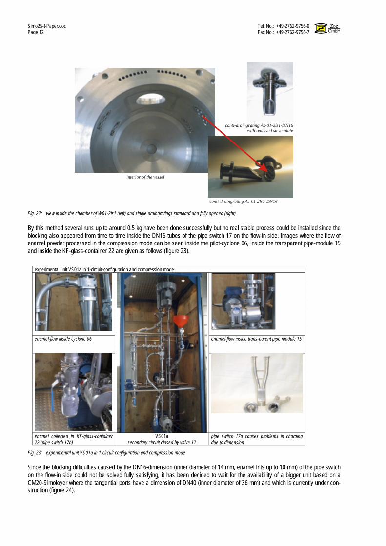
Simo25-I-Paper.doc Tel. No.: +49-2762-9756-0 Page 12 Fax No.: +49-2762-9756-7
interior of the vessel
conti-draingrating As-01-2ls1-DN16
conti-draingrating As-01-2ls1-DN16with removed sieve-plate
Fig. 22: view inside the chamber of W01-2ls1 (left) and single draingratings standard and fully opened (right)
By this method several runs up to around 0.5 kg have been done successfully but no real stable process could be installed since the blocking also appeared from time to time inside the DN16-tubes of the pipe switch 17 on the flow-in side. Images where the flow of enamel powder processed in the compression mode can be seen inside the pilot-cyclone 06, inside the transparent pipe-module 15 and inside the KF-glass-container 22 are given as follows (figure 23).
experimental unit VS01a in 1-circuit-configuration and compression mode
enamel-flow inside cyclone 06 enamel-flow inside trans-parent pipe module 15
enamel collected in KF-glass-container 22 (pipe switch 17b)
VS01a secondary circuit closed by valve 12
pipe switch 17a causes problems in charging due to dimension
Fig. 23: experimental unit VS01a in 1-circuit-configuration and compression mode
Since the blocking difficulties caused by the DN16-dimension (inner diameter of 14 mm, enamel frits up to 10 mm) of the pipe switch on the flow-in side could not be solved fully satisfying, it has been decided to wait for the availability of a bigger unit based on a CM20-Simoloyer where the tangential ports have a dimension of DN40 (inner diameter of 36 mm) and which is currently under con-struction (figure 24).

Tel. No.: +49-2762-9756-0 Simo25-I-Paper.doc.DOC Fax No.: +49-2762-9756-7 Page 13
Fig. 24: W20-20ls1, semi-continuously grinding unit with DN40 tangential ports
The results insofar are expected for part II/III of this work. Here the next step has been the investigation of auto-batch operation in compression mode (see chapter 5). For this the VS01a-unit is used in exactly the same configuration as before, only the charging of the frits is not done via the injection unit 26ff but done batch-wise via the standard main-port p01. In principle auto-batch means that the gas flow is used to transport the starting material into the grinding chamber, the processing is done in batch and then the gas flow is used again to transport the powder (ground material) out of the vessel into the closed circuit and then separated by the cyclone. By this procedure the significant disadvantage of in relation very long discharging times (see chapter 4) can be solved since the time is cut to a very much shorter period and most important, the Simoloyer does not have to be operated at lower speed, it can be oper-ated at lowest speed, so just that the rotor is going a little bit around in order to get the grinding media out of the way for the passing multiphase-flow. Insofar here only the second but most important part of this procedure is used since the starting material is manually fed into the vessel via main-port p01. The operation could be easily performed and repeated. The processing parameters are given as follows (figure 25):
VS01a, process parameters and used material in auto-batch operation, used material device VS01a, Simoloyer CM01, 2.7 kW, Maltoz 3.1 grinding unit W01-2ls1 (2 liter, semi-continuous, watercool.) grinding media chromium steel, 100Cr6, 5mm, 2 kg weight of initial frits charge 200 g product/ball weight ratio 1:10 rotational speed operation 1300 rpm processing time 2 min rotational speed discharging 200 rpm discharging tangential ports Z03 and Z04, pipe switch discharging time 3 min discharging velocity 0-32 ms-1 turbine power 0-1.5 kW, converter driven separation pilot-cyclone ZK70-L, auto-batch
tested materials (frits) No. 01 (Wendel) black-enamel frit (01)
Fig. 25: VS01a, process parameters and used material in auto-batch operation
The discharging procedure has been tested in dependency of the velocity of the multiphase-flow. The side-channel-turbine is con-trolled by a frequency-converter which is connected to the main-control unit. The velocity in the circuit has been measured via a bypass route. This procedure has been done in one-cyclone configuration and in two-cyclone configuration (see chapter 6). The yield-data (figure 26, left) shows that at a capacity of about 25 % of the turbine, which refers to a flow-velocity of about 10 ms-1 in the 3-D-velocity diagram (figure 26, right) at a 90° bypass-valve-position (fully open).

Simo25-I-Paper.doc Tel. No.: +49-2762-9756-0 Page 14 Fax No.: +49-2762-9756-7
VS01a, powder yield (left) and multiphase-flow velocity (right) in auto-batch operation
0
20
40
60
80
100
120
140
160
180
200
0 0,2 0,4 0,6 0,8 1 1,2 1,4 1,6
Side-channel-turbine power (kW)
Pow
dery
ield
(g/2
00g)
Pow
der y
ield
(g/2
00g)
0% 50% 100% one-cyclon model (1)two-cyclon model cyclon 1two cyclon model cyclon 2
0°
90° 60°30°
yield after 3 minutes discharging in auto-batch velocity diagram
Fig. 26: VS01a, powder yield (left) and multiphase-flow velocity (right) in auto-batch operation
At this limit the maximum possible yield within 3 minutes discharging is reached at a level of about 90 %. Further increase of the velocity does not increase the yield. In other words, for this operation mode, the capacity of the turbine is larger than necessary and what is important here, the batch can be discharged at lowest rotational speed (200 rpm) in an acceptable time (3 min>90%). For reference with respect to the particle size, a low kinetic rollermill RM1 (see figure 08) has been used where the parameters are given as follows (figure 27).
process parameters of the reference test by a low kinetic rollermill RM1 in batch operation, used material device Rollermill RM1 grinding container RBS005 (0.5 liter) grinding media chromium steel, 100Cr6, 5mm, 1.7 kg weight of initial frits charge 70 g total filling ratio 70 % product/ball volume ratio 1:7 rotational speed 100 rpm processing time 5 h discharging/separation manually
tested materials (frits) No. 01 (Wendel) steel containers RBS*
Fig. 27: process parameters of the reference test by a low kinetic rollermill RM1 in batch operation
In the given results of laser diffraction (figure 28), the red curve shows the reference material produced by the rollermill, the blue exhibits the powder being obtained after 2.5 min processing in the VS01a, the green one after 5 minutes and the yellow one after 10 minutes in the auto-batch procedure.

Tel. No.: +49-2762-9756-0 Simo25-I-Paper.doc.DOC Fax No.: +49-2762-9756-7 Page 15
particle size distribution by laser diffraction
powder as processed
100040020010040201064210.4Particlesize [µm]
10
8
6
4
2
0
Volu
me
[%]
Particle Size of processed enamel red
red
green
green
blueblue
yellow
yellow
red RM1 5h d50: 1134 µm low kinetic blue VS01a 2.5 min d50: 27.26 µm green VS01a 5 min d50: 22.10 µm yellow VS01a 10 min d50: 9.12 µm
high kinetic
Red RM1 5h d50: 1134 µm low kinetic blue VS01a 2.5 min d50: 27.26 µm green VS01a 5 min d50: 22.10 µm yellow VS01a 10 min d50: 9.12 µm
high kinetic
Fig. 28: particle size distribution, VS01a and rollermill RM1
The particle size distribution of the enamel processed for 5 h in the 0.5 liter vessel on the rollermill with a d50 of more than 1100 µm does not meet at all the in chapter 2 described state of the art of low kinetic processing with an average particle size of 20 µm after a time of 4-5 h. The explanation here is that this data is based on commercial production, which means that large drummills in the size of 1000-5000 liter are used (see figure 05). Here the diameter of the vessel varies from 1.1 – 2.0 m. The vessel RBS005 has a di-ameter of 85 mm which is about 13-24 times smaller. Consequently the kinetic in this system is much lower and also the level of pressure inside the ball-packet is much lower since there are much less layers inside [3].
comparison of effort in processing time against particle size reduction time time-variation
-a- d50 d50-variation
-b- d50-variation/min
b : a 0 min 0 ca. 2000 µm 0
2.5 min + 2.5 min 27.26 µm - 1972.74 µm 789.09 µm 5 min + 2.5 min 22.10 µm - 5.16 µm 2.06 µm 10 min + 5.0 min 9.12 µm - 12.98 µm 2.59 µm
VS01a, starting frit and auto-batch processing after 2.5, 5 and 10 minutes
Fig. 29: comparison of effort in processing time against particle size reduction, VS01a
The comparison of the 3 different curves (figure 29) of the powder obtained by auto-batch processing in VS01a after 2.5, 5 and 10 minutes, show very well, that the main effort takes place below 2 minutes. This is of course very obvious anyway but it should be additionally taken into account, that in case of the 2.5 and the 5 minutes operation, a large number of particles build up a narrow peak around 1000 µm level. If now this fraction (as described under chapter 4) would be separated, the d50-value would be signifi-cantly moved to a lower level. Since this is not valid for the 10 minutes operation, the particle size reduction effort as given in the table (figure 29) would successively decrease. Furthermore in a high kinetic process a present fine particle fraction is significantly hindering the size reduction effort due to dumping effect, which means, that under constant extraction during semi-continuously processing in compression mode, the size reduction effort can be expected significantly higher. Taking this all into account, the difference between the laser diffraction results of the operation in depression mode (see chapter 6) and compression mode can probably be explained and it can be estimated, that it will be possible to reach similar results (around 6 µm) once the compression mode can be executed under the availability of the larger unit (based on CM20).
9. melting tests with produced powder, discussion of the tool-system and impurity effects
For the acceptance of the enamel in particular the contamination during processing is a sensitive matter. Since that the commercial processing is done in drummills with a ceramic lining, usually by alumina which is then also the material of the grinding media. In most of the products, in particular in those that are produced in large volumes, alumina contamination is not problematic, since the product itself contains small fractions of alumina or at least similar metal-oxides anyway. In some applications and in particular if the alumina contamination comes to higher levels caused by longer milling operations to reach particle sizes below 10 µm which is very

Simo25-I-Paper.doc Tel. No.: +49-2762-9756-0 Page 16 Fax No.: +49-2762-9756-7
difficult with the conventional ball-milling technique, it does cause unacceptable problems e.g. due to an opaque-change in sensitive colors. The work here has up to this point not at all taken care to avoiding Fe-impurities since first the processing itself should be explored and get under an acceptable level of control. In fact it is expected, due to the tremendous decrease of processing time and it’s princi-ple based on collision of grinding media and not shear and friction, that contamination by the milling tools might be controlled per-fectly. So from the beginning it was not clear, if a change from the metal-based milling tools to ceramic ones would be necessary at all. To not to change would of course be most preferably, because of the poor shock-resistibility of almost any ceramic in a high kinetic process and of course and simply because of costs. If a change will be identified to be necessary, milling tools by alumina will not be of any interest since previous work did show that the properties are suitable for the vessel lining which is not exposed to high kinetic but not at all for the rotor and in particular not for the grinding media [22]. A special type of fully stabilized zirconia does show up a solution for the media but not for the rotor [23]. The preferred solution today is in fact the application of this zirconia media and vessel and rotor by Si3N4. In order to easily get some early quality-data on the material produced by HEM, some melting test have been performed (figure 30). But no chemical analysis yet. For a melting test, a metal- or a ceramic substrate is cleaned and coated with a slurry made with the supplied powder and then heat-treated which is insofar a realistic compare to real application. By this it is easy to check for a to high level of impurities, for wettability and for the viscosity under the heat-treatment temperature.
melting tests of white and black enamel produced in VS01a
material 04 material 01 8 min 2.5 min 1.5 min 0 min reference 2 min
processing time in auto-batch mode
Fig. 29: melting tests of white and black enamel
Metal impurities, in particular those containing Ni cause a sensitive change of color in case of white enamel, even in the range of 100ppm-level. Also Fe-impurities can easily be identified in case of light colored enamel since after heat-treatment they cause black oxide spots in the coating. Since the vessel as well as the base of the rotor of the used Simoloyer is made by Cr-Ni-steel, white enamel has been chosen for the first tests. The second series has been applied for black enamel. Compared to the applied white enamel without any processing, the 8 minutes sample shows a clear change of color to slightly yellow. The 2.5 minutes one very much less and the 1.5 minutes almost no change. The enamel has been applied on a metal-substrate, the black one on a ceramic plate which has been fixed in the furnace on a small angel, so that after cooling the viscosity can be judged to the reference material which is a commercial enamel material. A slight difference can be observed where this up to now is not identified as a difficulty. The tests with the white enamel do support the possibility that in case of further decrease of processing time, a change of the material of the milling tools at least for the material tested here might be avoided. An impor-tant attempt may be also not to avoid metal in principle but to avoid Ni-metal. On the other hand, once using the before described ceramic system, this can be of a high potential for high quality materials.

Tel. No.: +49-2762-9756-0 Simo25-I-Paper.doc.DOC Fax No.: +49-2762-9756-7 Page 17
10. Conclusions, Outlook, Acknowledgement & References Summary The state of the art of processing Enamels and Glass Fluxes has been shown, applications have been given. The principle of High Kinetic Processing (HEM, MA, RM) has been explained, examples of applications have been given. High Energy Milling has been applied for the processing of enamels in the initial approach in batch operation, then in semi-continuously operation using depression and finally in the compression mode. Here an experimental plant VS01a based on a Si-moloyer CM01-2ls1 originally made for the processing of ductile metal flakes has been used. The general principle is a multiphase-flow of a carrier gas fed and separated outside the milling chamber. Powder characterization has been given by SEM and Laser Diffraction, the flow velocity has been determined. Contamination and the tool system have been discussed and melting tests have been reported. Results Experiments in initial batch phase did show up a potential, that HEM might be a technique to produce enamel powder in a much shorter time and possibly could reach finer particles than the conventional low kinetic ball milling technique. A batch operation with extremely short milling times can not be used commercially since the relation between discharging and opera-tion is not expected to lead to unique products. In an initial continuously testing phase which could be set to a stable lab-scale production in semi-continuously operation in depres-sion mode, enamel powder could successfully be processed from the starting frits in 4-10 mm range to powder with a d50 of about 6 µm in a processing time below 1 minute. In comparison to the common process, this is 480-600 times faster and the particles are 2.5 - 3.3 times smaller. The goal for an industrial production is the application of the semi-continuously route in compression mode where a high pressure carrier gas is used. This could not be set up in a stable process since the inlet-piping of the experimental unit VS01a made for the processing of metal flakes were to small for the up to 10 mm large starting enamel frits. The then tested auto-batch procedure, where the feeding via this piping is skipped, did show promising results. The contamination discussion and melting tests have been very promising, too and show a high potential of either being able to perform the processing without ceramic tools since the process is so fast and based on collision or performing the process with ceramic tools to a better quality than available today or booth. Outlook The next important step is to set up a semi-continuous unit in compression mode in larger scale based on a CM20 Simoloyer since here the piping into the vessel has not a DN16 dimension with an inner diameter of 14 mm but a DN40 dimension with an inner diameter of 36 mm which is considered to be large enough to easily transport starting frits up to 10 mm scale into the grinding cham-ber by the multiphase flow. If it will be possible to set up the processing itself in a stable and then large industrial scale, which is already expected for the CM20-base-system, careful attention has to be given to contamination. The produced powders will have to be examined by chemical analy-sis, further melting tests have to be performed and maybe ceramic tool systems that are already available will have to be applied. In case this processing route will be fully available for commercial production, a high possibility of insitu adaptation of further follow-up processing steps like in particular particle coating with organics like silan, teflon, stearic acid, PVC-wax and others to improve wettability and avoid agglomeration before pasting etc., is expected. Message This dry and high kinetic processing route does promise an increase of quality at a tremendous decrease of producing time conse-quently with a decrease of cost and an increase of product flexibility at the same time. If this promising will become true must be found out by present and future work which shall later be reported in part II/III of this work. Acknowledgement The authors appreciate and acknowledge the important contribution of
The State of Nordrhein-Westfalen, Germany
for the main funding of TPW-project continuously and monitored flake-production by HEM with aerodynamic
separation & classification and rapid particle size reduction of brittle solids (aux. target, enamel) project no. 2507200

Simo25-I-Paper.doc Tel. No.: +49-2762-9756-0 Page 18 Fax No.: +49-2762-9756-7
References
[01] K. Schönert: Über die Eigenschaften von Bruchflächen, Chemie-Ingenieur-Technik Vol. 46, 1974, pp. 711-752 [02] H. Zoz: Keramische Zeitschrift, Vol. 47, 1995, pp. 190-92 [04] H. Zoz: Performance of the Simoloyer, 4th International Conference on Powder Metallurgy in Aerospace, Defense and Demanding Applications, eds. P.S.
Goodwin, R.B. Schwarz, in Annaheim, Los Angeles, USA, May 08-10, 1995 [05] J.S. Benjamin, Metall. Trans., Vol. 1, 2943 (1970) [06] J.S. Benjamin, T.E. Volin, Metall. Trans. Vol. 5, 1929 (1974) [07] H. Zoz: Mechanical Alloying, Powder Metallurgy in Aerospace, Defense and Demanding Applications, 1995, eds P.S. Goodwin, R.B. Schwarz [08] H. Zoz, H. Ren, N. Späth: Improved Ag-SnO2 Electrical Contact Material Produced by Mechanical Alloying, Proceeding of 1998 Powder Metallurgy World
Congress & Exhibition, Granada, Spain, October 18-22, 1998 [09] H. Zoz, D. Ernst, R. Reichardt, High Energy Milling / Mechanical Alloying / Reactive Milling, 3rd International Symposium of the school of chemical engi-
neering, University of Mexico City, May 1998 [10] H. Zoz, D. Ernst, I. S. Ahn, W.H. Kwon, Mechanical Alloying of Ti-Ni-based Materials using the Simoloyer®, TMS Annual Meeting 1997, eds. C.M. Ward-
Close, F.H. Froes, S.S. Cho, D.J. Chellman: Synthesis/Processing of lightweight Metallic Materials, (Proceedings 1997) [11] H. Zoz, D. Ernst, H. Weiss, M. Magini, C. Powell, C. Suryanarayana, F.H. Froes, Mechanical Alloying of Ti-24Al-11Nb (at%) using the Simoloyer® ( Zoz -
horizontal rotary ball mill), Part I, ISMANAM 96 / Rome, Proceedings [12] H. Zoz, R. Reichardt, H. Ren, Energy Balance during Mechanical Alloying, Measurement and Calculation Method supported by the Maltoz®-software,
PM2Tech´99 Conference MPIF/APMI, June 20 – 24, Vancouver, Proceedings in print [13] CRAFT Project BE-S2-3506 Ctr BRST-CT98-5490: Advanced Hard Coatings based on Ceramic Nanocomposites, 1998- [14] J.Y. Chung, J. Kim, Y.D. Kim, Formation of Nanocrystalline Fe-Co Powders Produced by Mechanical Alloying, Dept. of Metallurgy and Materials Science,
Hanyang University, Ansan, Korea, 1999 [15] H. Zoz, H.U.Benz, K. Hüttebräucker, L. Furken, H. Ren, R. Reichardt, Stellite bearings for liquid Zn-/Al-Systems with advanced chemical and physical
properties by Mechanical Alloying and Standard-PM-Route, Part I, KPMI Spring Meeting, April 7th, 2000, Hanyang University, Seoul, Korea [16] H. Zoz, D. Ernst, T. Mizutani, H. Okouchi, Simoloyer®* CM100s, semi-continuously Mechanical Alloying in a production scale using Cycle Operation-Part I,
Advances in Powder Metallurgy & Particulate Materials–1997, PM2Tech´97, Chicago, Vol.2, p.11-35, 1997 [17] Brite-Euram Project BE-95-1321, Novel Processing Technique for AgSnO2 Electrical Contact Materials, 1996 – 1999 [18] H. Zoz, R. Reichardt, H. Ren, H.U.Benz, Ductile Metal Flakes based on [Au], [Ag], [Cu], [Ti], [Al], [Ni] and [Fe] by High Energy Milling (HEM) – Part I,
PM2Tech´99 Conference MPIF/APMI, June 20 – 24, Vancouver, Proceedings in print [19] Report of Brite Euram Project BE-95-1231, Novel processing technique for AgSnO2. electrical contact Materials, 1996-1999 [20] Patent No. 2644284, 14/09/90 CLAL, Nouveaux matériaux à base d´argent et d´oxyde d´étain pour la réalisation de contacts électriques. [21] R.M. Davis, B. McDermott, C.C. Koch, Mechanical Alloying of Brittle Materials, Metall. Trans. Vol. 19a, 2867 (1988) [22] H. Zoz: HEM/MA/RM – Devices in use, 3rd Intern. Symp. of THE SCHOOL OF CHEMICAL ENGINEERING, May 27-29, 1998 [23] H. Ren and H Zoz, Ceramic Powder using High Energy Milling, ICCI Orlando, Orlando, 1999, Paper