high-output alternator installation guidecandela-sales.com/s/dc power installation...high-output...
TRANSCRIPT
High-Output Alternator Installation Guide
DC Power Engineering, Inc. 9339 Douglas Drive, Riverside, CA 92503 (888) 441-0144 phone
(951) 509-4517 fax http://www.dcpowerinc.com/
Congratulations on your purchase of the finest high-output alternator available at any price! This universal installation guide covers general installation procedures that apply to all of our alternators. Should you require assistance for your specific application, either contact the dealer you purchased the alternator from or contact us directly at (888) 441-0144. Proper installation of your new alternator is imperative to ensure that it works properly and delivers what we promise, as well as offering you the reliability that DC Power high-output alternators are famous for! Tools & Supplies Required in addition to Various Hand Tools: Digital Multi Meter Crimp Tool designed for large gauge cable OR Star washers Wire cutters Propane / Mapp Gas torch & 60/40 solder Cable ties Razor blade Drill & wire brush Wire of appropriate size Wire strippers Safety Glasses Ring Terminals STEP 1: Remove the battery negative ( - ) cable
STEP 2: Verify the charge state of the battery (or batteries)
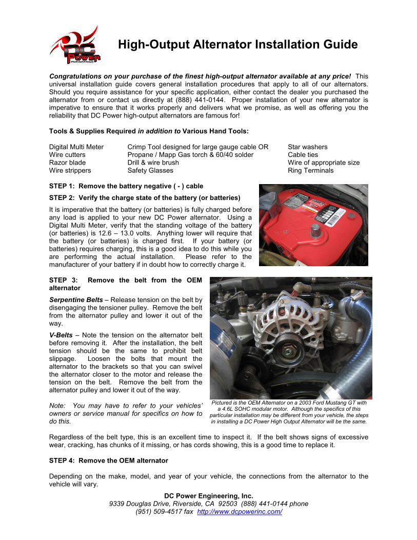
It is imperative that the battery (or batteries) is fully charged before any load is applied to your new DC Power alternator. Using a Digital Multi Meter, verify that the standing voltage of the battery (or batteries) is 12.6 – 13.0 volts. Anything lower will require that the battery (or batteries) is charged first. If your battery (or batteries) requires charging, this is a good idea to do this while you are performing the actual installation. Please refer to the manufacturer of your battery if in doubt how to correctly charge it.
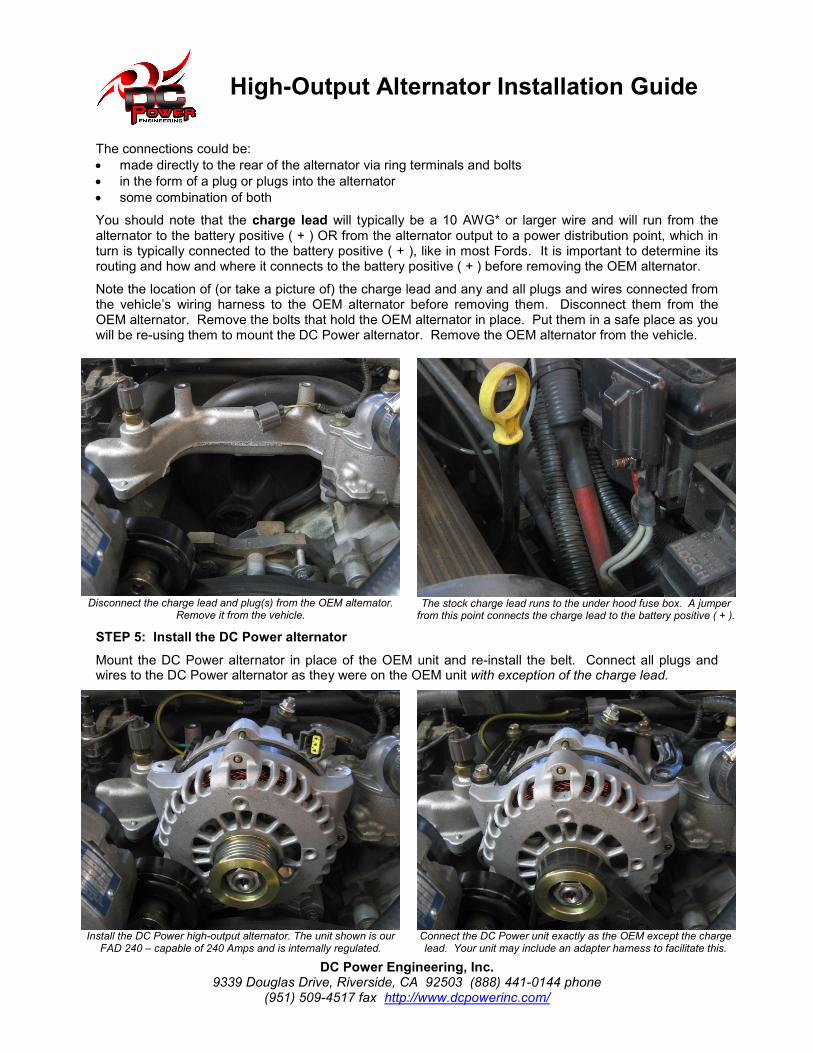
STEP 3: Remove the belt from the OEM alternator
Serpentine Belts – Release tension on the belt by disengaging the tensioner pulley. Remove the belt from the alternator pulley and lower it out of the way.
V-Belts – Note the tension on the alternator belt before removing it. After the installation, the belt tension should be the same to prohibit belt slippage. Loosen the bolts that mount the alternator to the brackets so that you can swivel the alternator closer to the motor and release the tension on the belt. Remove the belt from the alternator pulley and lower it out of the way. Note: You may have to refer to your vehicles’ owners or service manual for specifics on how to do this.
Pictured is the OEM Alternator on a 2003 Ford Mustang GT with a 4.6L SOHC modular motor. Although the specifics of this
particular installation may be different from your vehicle, the steps in installing a DC Power High Output Alternator will be the same.
Regardless of the belt type, this is an excellent time to inspect it. If the belt shows signs of excessive wear, cracking, has chunks of it missing, or has cords showing, this is a good time to replace it. STEP 4: Remove the OEM alternator Depending on the make, model, and year of your vehicle, the connections from the alternator to the vehicle will vary.
High-Output Alternator Installation Guide
DC Power Engineering, Inc. 9339 Douglas Drive, Riverside, CA 92503 (888) 441-0144 phone
(951) 509-4517 fax http://www.dcpowerinc.com/
The connections could be:
• made directly to the rear of the alternator via ring terminals and bolts
• in the form of a plug or plugs into the alternator
• some combination of both
You should note that the charge lead will typically be a 10 AWG* or larger wire and will run from the alternator to the battery positive ( + ) OR from the alternator output to a power distribution point, which in turn is typically connected to the battery positive ( + ), like in most Fords. It is important to determine its routing and how and where it connects to the battery positive ( + ) before removing the OEM alternator.
Note the location of (or take a picture of) the charge lead and any and all plugs and wires connected from the vehicle’s wiring harness to the OEM alternator before removing them. Disconnect them from the OEM alternator. Remove the bolts that hold the OEM alternator in place. Put them in a safe place as you will be re-using them to mount the DC Power alternator. Remove the OEM alternator from the vehicle.
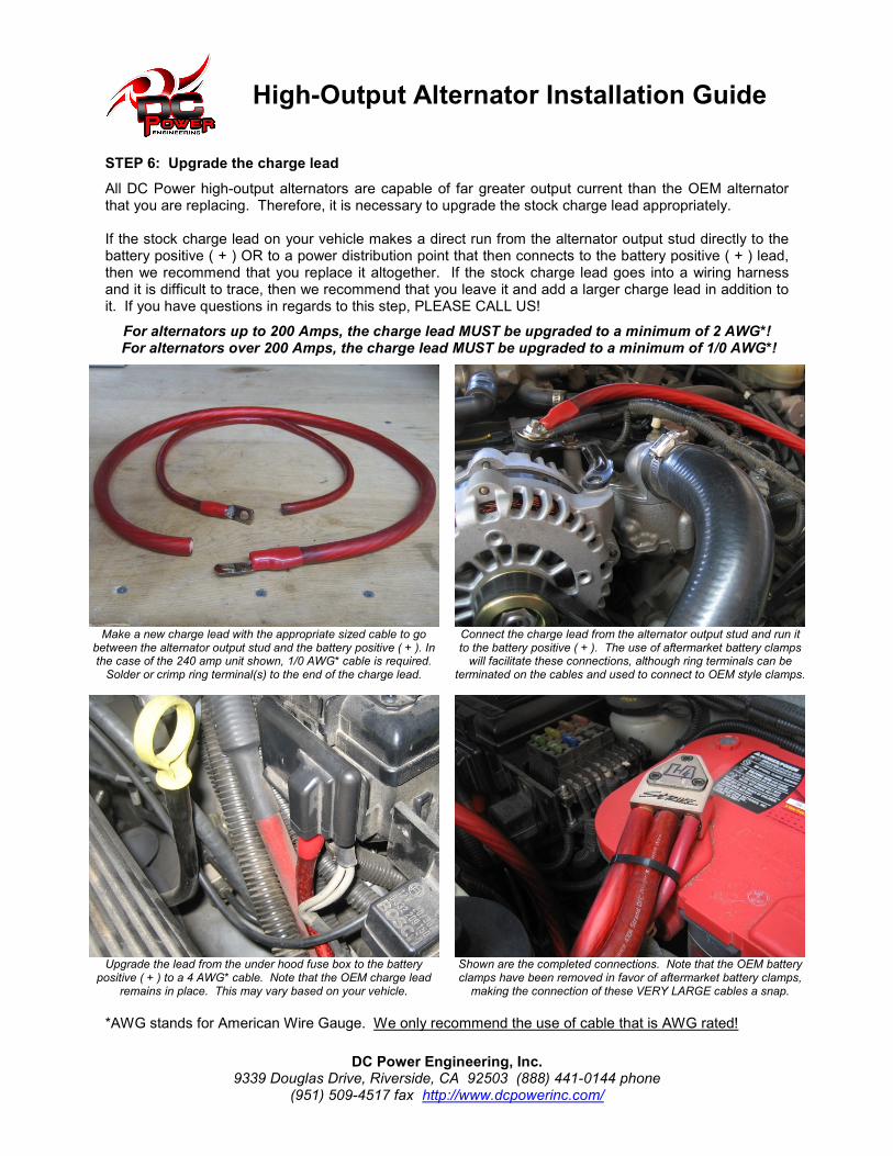
Disconnect the charge lead and plug(s) from the OEM alternator.
Remove it from the vehicle.
The stock charge lead runs to the under hood fuse box. A jumper from this point connects the charge lead to the battery positive ( + ).
STEP 5: Install the DC Power alternator
Mount the DC Power alternator in place of the OEM unit and re-install the belt. Connect all plugs and wires to the DC Power alternator as they were on the OEM unit with exception of the charge lead.
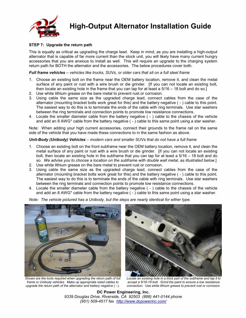
Install the DC Power high-output alternator. The unit shown is our
FAD 240 – capable of 240 Amps and is internally regulated.
Connect the DC Power unit exactly as the OEM except the charge lead. Your unit may include an adapter harness to facilitate this.
High-Output Alternator Installation Guide
DC Power Engineering, Inc. 9339 Douglas Drive, Riverside, CA 92503 (888) 441-0144 phone
(951) 509-4517 fax http://www.dcpowerinc.com/
STEP 6: Upgrade the charge lead
All DC Power high-output alternators are capable of far greater output current than the OEM alternator that you are replacing. Therefore, it is necessary to upgrade the stock charge lead appropriately. If the stock charge lead on your vehicle makes a direct run from the alternator output stud directly to the battery positive ( + ) OR to a power distribution point that then connects to the battery positive ( + ) lead, then we recommend that you replace it altogether. If the stock charge lead goes into a wiring harness and it is difficult to trace, then we recommend that you leave it and add a larger charge lead in addition to it. If you have questions in regards to this step, PLEASE CALL US!
For alternators up to 200 Amps, the charge lead MUST be upgraded to a minimum of 2 AWG*! For alternators over 200 Amps, the charge lead MUST be upgraded to a minimum of 1/0 AWG*!
Make a new charge lead with the appropriate sized cable to go
between the alternator output stud and the battery positive ( + ). In the case of the 240 amp unit shown, 1/0 AWG* cable is required. Solder or crimp ring terminal(s) to the end of the charge lead.
Connect the charge lead from the alternator output stud and run it to the battery positive ( + ). The use of aftermarket battery clamps will facilitate these connections, although ring terminals can be
terminated on the cables and used to connect to OEM style clamps.
Upgrade the lead from the under hood fuse box to the battery
positive ( + ) to a 4 AWG* cable. Note that the OEM charge lead remains in place. This may vary based on your vehicle.
Shown are the completed connections. Note that the OEM battery clamps have been removed in favor of aftermarket battery clamps, making the connection of these VERY LARGE cables a snap.
*AWG stands for American Wire Gauge. We only recommend the use of cable that is AWG rated!
High-Output Alternator Installation Guide
DC Power Engineering, Inc. 9339 Douglas Drive, Riverside, CA 92503 (888) 441-0144 phone
(951) 509-4517 fax http://www.dcpowerinc.com/
STEP 7: Upgrade the return path
This is equally as critical as upgrading the charge lead. Keep in mind, as you are installing a high-output alternator that is capable of far more current than the stock unit, you will likely have many current hungry accessories that you are anxious to install as well. This will require an upgrade to the charging system return path for BOTH the alternator and the accessories. The below procedures cover both.
Full frame vehicles – vehicles like trucks, SUVs, or older cars that sit on a full steel frame
1. Choose an existing bolt on the frame near the OEM battery location, remove it, and clean the metal surface of any paint or rust with a wire brush or die grinder. [If you can not locate an existing bolt, then locate an existing hole in the frame that you can tap for at least a 5/16 – 18 bolt and do so.]
2. Use white lithium grease on the bare metal to prevent rust or corrosion. 3. Using cable the same size as the upgraded charge lead, connect cables from the case of the
alternator (mounting bracket bolts work great for this) and the battery negative ( - ) cable to this point. The easiest way to do this is to terminate the ends of the cable with ring terminals. Use star washers between the ring terminals and connection points to promote low resistance connections.
4. Locate the smaller diameter cable from the battery negative ( - ) cable to the chassis of the vehicle and add an 8 AWG* cable from the battery negative ( - ) cable to this same point using a star washer.
Note: When adding your high current accessories, connect their grounds to the frame rail on the same side of the vehicle that you have made these connections to in the same fashion as above.
Unit-Body (Unibody) Vehicles – modern cars and smaller SUVs that do not have a full frame
1. Choose an existing bolt on the front subframe near the OEM battery location, remove it, and clean the metal surface of any paint or rust with a wire brush or die grinder. [If you can not locate an existing bolt, then locate an existing hole in the subframe that you can tap for at least a 5/16 – 18 bolt and do so. We advise you to choose a location on the subframe with double wall metal, as illustrated below.]
2. Use white lithium grease on the bare metal to prevent rust or corrosion. 3. Using cable the same size as the upgraded charge lead, connect cables from the case of the
alternator (mounting bracket bolts work great for this) and the battery negative ( - ) cable to this point. The easiest way to do this is to terminate the ends of the cable with ring terminals. Use star washers between the ring terminals and connection points to promote low resistance connections.
4. Locate the smaller diameter cable from the battery negative ( - ) cable to the chassis of the vehicle and add an 8 AWG* cable from the battery negative ( - ) cable to this same point using a star washer.
Note: The vehicle pictured has a Unibody, but the steps are nearly identical for either type.
Shown are the tools required when upgrading the return path of full frame or Unibody vehicles. Make up appropriate sized cables to upgrade the return path of the alternator and battery negative ( - ).
Locate an existing hole in a thick part of the subframe and tap it to accept a 5/16-18 bolt. Grind the paint to ensure a low resistance connection. Use white lithium grease to prevent rust or corrosion.

High-Output Alternator Installation Guide
DC Power Engineering, Inc. 9339 Douglas Drive, Riverside, CA 92503 (888) 441-0144 phone
(951) 509-4517 fax http://www.dcpowerinc.com/
Connect the return path cable to the battery negative ( - ) terminal.
Note the use of an aftermarket battery clamp to facilitate this.
Connect the return path cable to one of the mounting points of the
alternator. Use a star washer under the ring terminal.
Connect the return path cables from the alternator and from the battery negative ( - ) to the subframe. Use star washers between the subframe and ring terminal, and between multiple ring terminals to ensure a low resistance connection. Tighten this bolt securely with a long handled ratchet. This step is VERY important!
Upgrade the OEM accessory ground lead from the battery ( - ) to the chassis with an 8 AWG* lead from the battery negative ( - ).
We can not stress enough how important it is to upgrade the return path. This is not an optional step! STEP 8: Reconnect the negative ( - ) battery cable to the battery The installation of your DC Power high-output alternator is now complete. Your installation should look something like the photo at the right. You are now ready to test it for proper operation. Please refer to the following page for instructions how to do so.
The completed installation ⇒
High-Output Alternator Installation Guide
DC Power Engineering, Inc. 9339 Douglas Drive, Riverside, CA 92503 (888) 441-0144 phone
(951) 509-4517 fax http://www.dcpowerinc.com/
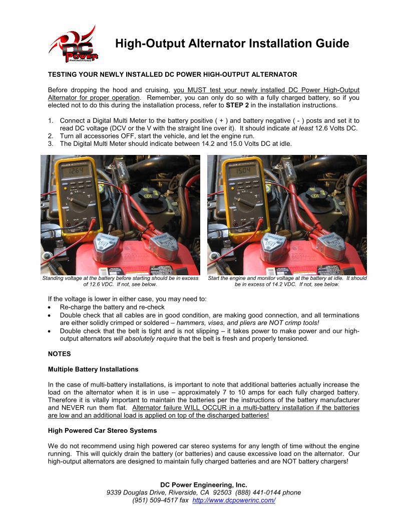
TESTING YOUR NEWLY INSTALLED DC POWER HIGH-OUTPUT ALTERNATOR Before dropping the hood and cruising, you MUST test your newly installed DC Power High-Output Alternator for proper operation. Remember, you can only do so with a fully charged battery, so if you elected not to do this during the installation process, refer to STEP 2 in the installation instructions. 1. Connect a Digital Multi Meter to the battery positive ( + ) and battery negative ( - ) posts and set it to
read DC voltage (DCV or the V with the straight line over it). It should indicate at least 12.6 Volts DC. 2. Turn all accessories OFF, start the vehicle, and let the engine run. 3. The Digital Multi Meter should indicate between 14.2 and 15.0 Volts DC at idle.
Standing voltage at the battery before starting should be in excess
of 12.6 VDC. If not, see below.
Start the engine and monitor voltage at the battery at idle. It should
be in excess of 14.2 VDC. If not, see below.
If the voltage is lower in either case, you may need to:
• Re-charge the battery and re-check
• Double check that all cables are in good condition, are making good connection, and all terminations are either solidly crimped or soldered – hammers, vises, and pliers are NOT crimp tools!
• Double check that the belt is tight and is not slipping – it takes power to make power and our high-output alternators will absolutely require that the belt is fresh and properly tensioned.
NOTES Multiple Battery Installations In the case of multi-battery installations, is important to note that additional batteries actually increase the load on the alternator when it is in use – approximately 7 to 10 amps for each fully charged battery. Therefore it is vitally important to maintain the batteries per the instructions of the battery manufacturer and NEVER run them flat. Alternator failure WILL OCCUR in a multi-battery installation if the batteries are low and an additional load is applied on top of the discharged batteries! High Powered Car Stereo Systems We do not recommend using high powered car stereo systems for any length of time without the engine running. This will quickly drain the battery (or batteries) and cause excessive load on the alternator. Our high-output alternators are designed to maintain fully charged batteries and are NOT battery chargers!