high-performance multi-coil inductive power … for electromagnetic research methods and application...
TRANSCRIPT
Forum for Electromagnetic Research Methods and Application Technologies (FERMAT)
1
Abstract— Inductive power transmission is widely used
to energize implantable microelectronic devices (IMDs),
and recharge batteries in mobile electronics and electric
cars. Power transfer efficiency (PTE) and power delivered
to the load (PDL) are two key parameters in wireless links.
To improve the PTE, additional coils have been added to
conventional 2-coil links to form 3- and 4-coil inductive
links. Several analytical methods for estimating PTE of
inductive links have been devised based on circuit and
electromagnetic theories. Here, we have analyzed the PTE
for multiple capacitively-loaded inductors based on both
circuit and coupled-mode theories. We have proven that
both methods basically result in the same set of equations
in steady state and either method can be applied for short-
or mid-range coupling conditions. Through our
comprehensive circuit analysis, we have also compared the
PTE and PDL of 2-, 3-, and 4-coil links. Our analysis
suggests that the 2-coil links are suitable when the coils are
strongly coupled and a large PDL is needed. Three-coil
links are the best when the coils are loosely coupled, the
coupling distance varies considerably, and large PDL is
necessary. Finally, 4-coil links are optimal when large PTE
is key, the coils are loosely coupled, and their relative
distance and alignment are stable.
Index Terms—Inductive Links, Wireless Power
Transmission, Resonance Circuits, Power Transfer
Efficiency, Near-Field, Coupled-Mode Theory.
I. INTRODUCTION
Inductive power transmission can be used to either
continuously power up a device or temporarily recharge its
batteries without any direct electrical contact between the
energy source and that device. A high efficiency power
amplifier (PA), connected to the main energy source on the
transmitter side (Tx), often drives the primary coil, which is
mutually coupled to a secondary coil on the receiver side (Rx),
which is connected to the load (RL). The load can cover a wide
range of applications from high performance and
sophisticated implantable microelectronic devices (IMD) with
relatively high-power consumption (>100 mW), such as
cochlear and retinal implants, to simple and low power radio
frequency identification (RFID) tags that cannot use primary
batteries due to their cost, size, or lifetime constraints[1]-[6].
The use of this technique to wirelessly transfer energy across
a short distance is expected to see an explosive growth over
the next decade to cut the power cord in charging mobile
electronic devices, operating small home appliances, and
energizing electric cars, which have higher power
consumptions in the order of hundreds of milliwatts to
kilowatts [7]-[12].
The mutual inductance between a pair of coupled coils, M,
is proportional to d-3, where d is the center-to-center spacing
between the coils when they are in parallel planes and
perfectly aligned [5]. A key requirement in all of the above
applications is to deliver sufficient power to the load with high
power transfer efficiency (PTE) when d is relatively large or
the coils are misaligned, i.e. when M is very small (PTE is
already large enough for small d). Large PTE is meant to
reduce heat dissipation within the coils, tissue exposure to AC
magnetic field, which can cause additional heat dissipation in
IMDs, size of the main energy source, and interference with
nearby electronics to satisfy regulatory requirements [13]-
High-Performance Multi-Coil Inductive Power
Transmission Links
Mehdi Kiani(1) and Maysam Ghovanloo(2)
(1) Pennsylvania State University, University Park, PA 16802
(Email: [email protected])
(2) Georgia Institute of Technology, Atlanta, GA 30308
(Email: [email protected])
(a)
(b) (c)
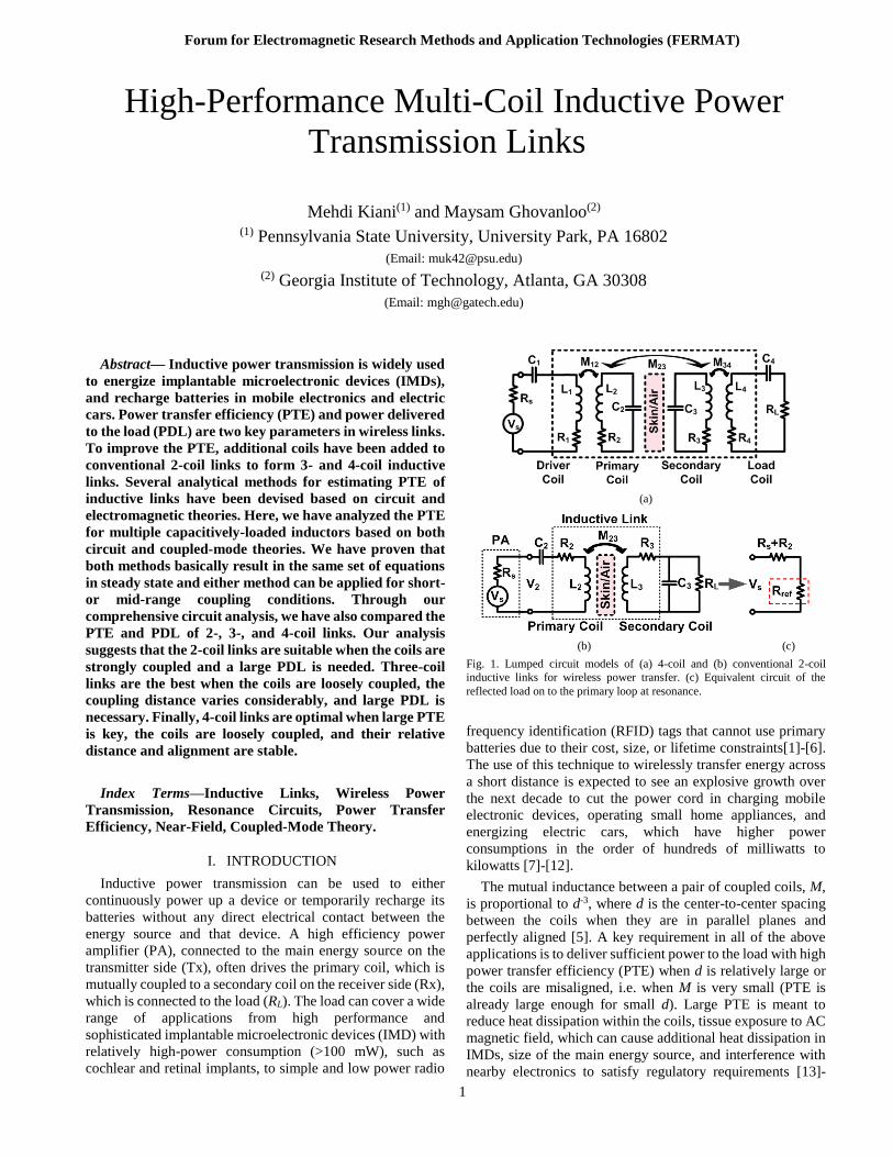
Fig. 1. Lumped circuit models of (a) 4-coil and (b) conventional 2-coil
inductive links for wireless power transfer. (c) Equivalent circuit of the
reflected load on to the primary loop at resonance.

Forum for Electromagnetic Research Methods and Application Technologies (FERMAT)
2
[15]. At the same time, the link should deliver sufficient power
to the load while considering practical limitations of the
energy source and the PA. When RL is constant, PDL would
be equivalent to the inductive link voltage gain all the way
from the source to the load. Increasing the source voltage, Vs
in Fig. 1a, to increase PDL can reduce the driver efficiency,
require larger transistors in the PA, and make it more difficult
and costly to meet the safety requirements.
Design, theoretical analysis, and geometrical optimization
of the conventional 2-coil inductive links have been covered
extensively in the literature over the last three decades [16]-
[27]. More recently, a 4-coil power transmission link was
proposed by physicists in [28] based on coupled-mode theory
(CMT) to further increase the PTE, particularly at large d. In
the 4-coil arrangement, which schematic diagram is shown in
Fig. 1a, a pair of coils is used on the Tx side, which are
referred to as the driver, L1, and primary, L2, coils. A second
pair of coils is used on the Rx side, which are referred to as
the secondary, L3, and load, L4, coils. All of these coils are
tuned at the same resonance frequency, f0, using capacitors C1
~ C4. The coils’ parasitic resistances are also shown by R1 ~
R4. The 4-coil method has so far been adopted for transferring
power to multiple small receivers, transcutaneous power
transmission for d = 10~20 mm, and recharging mobile
devices in [29], [30], and [31], respectively.
In this paper, we have analyzed multi-coil inductive links
in the form of 3- and 4-coil links utilizing both circuit and
coupled-mode theories, and compared them with their
conventional 2-coil counterpart. Our analyses show 1) circuit
and coupled-mode theories both results in the same set of
equations for PTE, 2) utilizing the 4-coil method increases the
PTE at large d at the cost of a significant reduction in the
power delivered to the load (PDL). Therefore, unless the
application requires a small amount of power (10s of mW or
less), a high driving voltage (Vs) will be required, which can
reduce the driver efficiency and lead to safety issues in
medical applications. 3) A 3-coil link, initially proposed in
[32], not only provides as high PTE as the 4-coil method but
also offers a PDL that is significantly higher than both 2- and
4-coil links at large d. In the following section we have
constructed a circuit-based theoretical framework to analyze
and compare 2-, 3-, and 4-coil inductive links. Section III
describes the theory of multi-coil links based on CMT.
Measurement results are included in Section IV, followed by
concluding remarks in Sections V.
II. CIRCUIT THEORY OF MULTI-COIL INDUCTIVE LINKS
Fig. 1b shows the simplified schematic diagram of a 2-coil
inductive link. It is known that the highest PTE across this link
can be achieved when both LC tanks are tuned at the same
resonance frequency, f0 [24]. The effect of the Rx side on the
Tx side can be modeled at resonance by calculating the
reflected impedance,
LsLref QQRRkQLkR 322
2
23320
2
23 )( , (1)
where k23=M23/√L2L3, Q2 = ω0L2/(Rs+ R2) , and Q3L = Q3QL/
(Q3+QL), in which Q3 = ω0L3/R3 and QL = RL/ω0L3 [5]. QL is
often referred to as the load quality factor, Rs is the loss
associated with the PA, and the value for M23 can be calculated
from [26]. Hence, the primary loop can be simplified at
resonance as the circuit shown in Fig. 1c.
To derive an equation for the PTE at resonance, we should
consider that the power provided by Vs divides between Rs+R2
and Rref, and the power delivered to Rref, i.e. the power that is
received by the secondary loop, divides between R3 and RL,
which are the only power consuming components on the Rx
side. This will lead to [24]
L
L
L
Lcoil
Q
Q
QQk
QQk 3
32
2
23
32
2
232 .
1 . (2)
Note that the first and second terms in (2) correspond to the
power division between Rs+R2 and Rref, and R3 and RL,
respectively.
The amount of power delivered to the load (PDL), on the
other hand, can be calculated by multiplying the power
provided by Vs, i.e. Vs2/2(Rs + R2+Rref), by the PTE from (2)
L
L
L
L
s
scoilL
Q
Q
QQk
QQk
RR
VP 3
2
32
2
23
32
2
23
2
2
2,)1()(2
. (3)
If the simple 2-coil inductive link in Fig. 1b is extended to
an m-coil link, in which 1st and mth coils are connected to the
energy source and load, respectively, the reflected load from
the (j+1)th coil to the jth coil can be found from
Ljjjjjjref QLkR )1(0
2
1,1, , j = 1, 2, … , m-1 (4)
where kj,j+1 is the coupling coefficient between the jth and
(j+1)th coils and all coils are tuned at the same resonance
frequency, f0. Q(j+1)L is the loaded quality factor of the (j+1)th
coil which can be found from
Ljjjj
j
jjrefj
j
jLQQk
Q
RR
LQ
)1(
2
1,1,
0
1
, j = 1, 2, …, m-1
(5)
where Qj = ω0Lj/Rj and Rj are the unloaded quality factor and
parasitic series resistance of the jth coil, Lj, respectively. It
should be noted that for the last coil, which is connected to the
load in series, QmL = ω0Lm/(Rm+RL) and for the first coil, which
is connected to the source, R1 also includes the source output
impedance, Rs. Therefore, assuming that the coupling between
non-neighboring coils is negligible, the PTE from the jth coil
to (j+1)th coil can be written as
Ljjjj
Ljjjj
jjrefj
jjref
jjQQk
QQk
RR
R
)1(
2
1,
)1(
2
1,
1,
1,
1,1
. (6)
Using (4), (5), and (6), the overall PTE in such a multi-coil
inductive link can be found from
L
mLm
j
jjcoilmQ
Q
1
1
1, , (7)
and the PDL from
coilm
Ls
scoilmL
QQkRR
VP
21
2
121
2
,1
1
)(2. (8)

Forum for Electromagnetic Research Methods and Application Technologies (FERMAT)
3
For (7) and (8) to be valid, all coils should be tuned at the same
resonance frequency to also achieve the highest PTE and PDL
between each neighboring pair of coils [24], and maximize the
PTE and PDL of the multi-coil link.
A. Optimal 2-Coil Power Transfer Link
The PTE profile of the 2-coil inductive link according to (2)
is a monotonically decreasing function of the coils’ coupling
distance, d23. However, for a given set of Q2, Q3 and k23 values,
there is an optimal load, RL,PTE = ω0L3QL,PTE, which can
maximize the PTE at that particular d23. QL,PTE can be found
by calculating the derivative of (2) vs. QL from
2/1
32
2
23
3,
)1( QQk
QQ PTEL
. (9)
The maximum PDL at a certain d23 can be achieved when
the reflected impedance from (1) matches the overall loss of
the primary coil, i.e. Rref = Rs + R2 [33]. It should also be noted
that in this condition, the PTE is always less than 50%,
because half of the power is dissipated in Rs + R2. Thus, the
coupling coefficient which maximizes PDL for a certain RL
can be found from,
2/1
32
,23)(
1
L
PDLQQ
k . (10)
Alternatively, by calculating the derivative of (3) vs. QL, one
can find the optimal load, RL,PDL = ω0L3QL,PDL, which can
maximize the PDL at a particular d23, where
32
2
23
3,
1 QQk
QQ PDLL
. (11)
It is important to note that according to (9) and (11), the
maximum PTE and PDL cannot be achieved simultaneously
with the same RL or d23. In the 2-coil links, each of these
conditions requires a specific set of k23, Q2, and Q3, which may
not be feasible within the designated constraints. On the other
hand, a multi-coil solution provides the designer with more
degrees of freedom to optimize the inductive link based on
either one of the above requirements. This is the basic idea
behind the 3- and 4-coil inductive links, despite their potential
negative impact on the size-constrained applications.
B. Three-Coil Power Transfer Inductive Link
The 3-coil inductive link circuit model, which comprises of
the primary coil, L2, on the Tx side and the secondary and load
coils (L3 and L4) on the Rx side, has been shown in Fig. 2. If
we ignore k24 due to large separation between L2 and L4, the
PTE of 3-coil link can be found by reflecting RL back to the
primary coil using (4) and calculating PTE from (6) and (7),
34234
43
2
3443
2
3432
2
23
43
2
3432
2
233 .
)]1)(1[(
))((
L
L
LL
Lcoil
Q
Q
QQkQQkQQk
QQkQQk
(12)
where
LL
L
QQkQQk
QQk
QQk
QQk
43
2
3432
2
23
32
2
23
32
2
23
32
2
2323
11
,
L
L
L
L
Q
Q
QQk
QQk 4
43
2
34
43
2
3434 .
1 .
(13)
Similarly, the PDL of the 3-coil link can be written as,
L
L
L
L
s
scoilL
Q
Q
QQkQQk
QQkQQk
RR
VP 4
2
43
2
3432
2
23
43
2
3432
2
23
2
2
3,)1(
))((
)(2
(14)
The problem with the optimal 2-coil power transfer link in
section II.A was that for a given set of Q2, Q3, and k23, the
optimal PTE could only be achieved for a certain load, RL,PTE,
which could be far from the nominal RL. In the 3-coil power
transfer inductive link, however, L3, L4 and M34 in Fig. 3 can
play the role of an impedance matching circuit (compare with
Fig. 1b), which can convert any arbitrary RL to RL,PTE. This is
equivalent to having a load quality factor of QL = QL,PTE in the
secondary loop of a 2-coil link, which was defined in (9).
This leverage in the design of the 3-coil links has been
provided by k342
Q3Q
4L term in (12)-(14). Lowering k34
2Q
3Q
4L
tends to increase η23 and at the same time reduces η34 in (13),
both of which affect the overall PTE in (12). To better
understand the PTE variations in a 3-coil inductive link, the
effects of k34 and d23 on the PTE are shown in Fig. 3a for the
coils specified in Table-I. The optimal value for k342
Q3Q
4L that
maximizes the PTE for a certain d23 (or k23) can be found by
differentiating (12) with respect to k34,
4/1
2
4
2
3
2
432
2
23
4/1
2
4
2
3
32
2
23,34
/1.11
RRQQk
QQkk L
L
PTE.
(15)
For a certain RL, if the choice of k34 in the design of a 3-coil
inductive link satisfies (15), then the reflected load onto the
secondary loop will satisfy (9) and maximizes the PTE.
Fig. 3b shows the effects of k34 and d23 on the PDL of the 3-
coil inductive link in Table-I, based on (14). It can be seen that
there are optimal values for both k34 and k23, which can
maximize PDL, and in order to find them, (14) should be
differentiated with respect to k34 and k23,
2/1
32
43
2
34,23
1
QQkk L
PDL , (16)
Fig. 2. Lumped circuit model of the 3-coil inductive link.

Forum for Electromagnetic Research Methods and Application Technologies (FERMAT)
4
2/1
43
32
2
23,34
1
L
PDLQQ
QQkk . (17)
These values result in the reflected load on to the primary coil
to be equal to R2, in order to satisfy (11) for any arbitrary RL.
C. Four-Coil Power Transfer Inductive Link
The PTE in the 4-coil inductive link, shown in Fig. 1a, can
be found by reflecting the resistive components to the left
from the load coil back to the driver coil loop, one stage at a
time using (4), and calculating the portion of the power that is
delivered to the following stage, using (6), until it reaches RL
L
L
LL
Lcoil
Q
Q
QQkQQkQQkQQkQQk
QQkQQkQQk 4
43
2
3432
2
2332
2
2343
2
3421
2
12
43
2
3432
2
2321
2
124
]1].[)1).(1[(
))()((
(18)
To simplify this equation, k13, k14 and k24 have been
neglected in comparison to coupling coefficients between
neighboring coils, which are k12, k23 and k34 [30]. Using the
same method, the PDL in the 4-coil inductive link can be
found from
L
L
L
L
s
scoilL
Q
Q
QQkQQkQQk
QQkQQkQQk
RR
VP 4
2
32
2
2343
2
3421
2
12
43
2
3432
2
2321
2
12
1
2
4,])1).(1[(
))()((
)(2
(19)
The PTE between loosely coupled primary and secondary
coils, L2 and L3, is the dominant factor in determining the
overall PTE of the 4-coil link at a large coupling distance, d23.
Similar to 3-coil links, when RL reflects onto L3 from L4
according to (4), it reduces the quality factor of L3 from Q3 =
ω0L3/R3 to
L
LQQk
43
2
34
33
1 , (20)
based on (5). In order to maximize the PTE between L2 and
L3, Q3L in (20) should satisfy (9). k34 in (20) is, therefore, a key
parameter in 4-coil links which allows designers to maximize
the PTE for any arbitrary RL. As mentioned in section II.A,
this flexibility is not available in a 2-coil link. Similarly, the
total impedance in the secondary coil reflects onto the primary
coil, based on (4), and reduces the primary coil’s quality factor
from Q2 = ω0L2/(Rs+R2) to
L
LQQk
32
2
23
22
1 . (21)
From (21) and (6) it can be inferred that a strong coupling
between the primary and secondary coils (i.e. a high k23)
reduces Q2L and consequently η12, which is the PTE between
L1 and L2. It should also be noted that according to (21), Q2L
is roughly proportional to k23-2
, where k23 is further proportional
to d23 -3
[5]. Therefore, Q2L is proportional to d236
, implying that
η12 will significantly reduce at small d23 if k12 is not chosen
large enough. This effect has been demonstrated in Fig. 4a,
which shows the PTE of a 4-coil inductive link as a function
of k12 and d23 for the coils specified in Table I. It can be seen
that for small k12, near the origin, the PTE has dropped at short
coupling distances due to the small η12. Therefore, small Q1
and k12 will result in a significant drop in η12 at small coupling
(a)
(b)
Fig. 3. Simulated (a) PTE and (b) PDL for a 3-coil inductive link as a function
of k34 and d23 for the coils in Table I. Vs = 1 V and RL = 100 .
(a)
(b)
Fig. 4. Simulated (a) power transfer efficiency (PTE) and (b) power delivered
to the load (PDL) for a 4-coil inductive link as a function of k12 and d23 when
k34 = 0.22 for the coils specified in Table I. Vs = 1 V and RL = 100 .

Forum for Electromagnetic Research Methods and Application Technologies (FERMAT)
5
distances according to (6).
In order to avoid the above problem, k12 should be kept
large, which according to (4) results in a large reflected load
onto L1. This can reduce the available power from the source,
according to (8), unless Vs is increased. However, large Vs can
cause safety issues in medical applications, and this is a major
disadvantage of the 4-coil arrangement for inductive power
transfer to IMDs, particularly when a high PDL is required.
Fig. 4b shows the PDL from (19) as a function of k12 and
d23 for the coils in Table I. It can be seen that increasing k12
results in reducing the PDL when Vs is kept constant. A
comparison between Figs. 4a and 4b is instructive by
observing that the high PTE and high PDL areas of these
surfaces do not overlap, which means that in a 4-coil inductive
link there is always a compromise between the highest PTE
that can be achieved while delivering sufficient power to the
load without surpassing safe Vs limits.
The optimal PTE with respect to d23 in a 4-coil link can be
found by differentiating (18) in terms of k23, which gives
2/1
32
43
2
3421
2
12
,23
)1.(1
QQkQQkk
L
PTE . (22)
This equation helps designers to shift the peak of the PTE
profile in Fig. 4a towards the nominal coupling distance for
certain k12 and k34 values. Similarly, the optimal PDL, can be
found by differentiating (19) in terms of k23, which results in
2/1
32
43
2
3421
2
12,23
)1).(1(
QQkQQkk L
PDL (23)
D. Optimal Multi-coil Link
A comparison between Figs. 2 and 4 reveals a key
advantage of the 3-coil links over their 4-coil counterparts,
which suffer from poor PDL in areas of the curve that PTE is
high (see section II.C). Comparing Figs. 3a and 3b, however,
shows that by proper choice of k23 and k34, which depend on
the coil values and their geometries, designers can establish 3-
coil inductive power transfer links that offer both high PTE as
well as high PDL. Another advantage of the 3-coil links is that
they are not affected by the inefficiency between the driver
and primary coils (12 < 1). However, in the applications that
involve small PDL or large Rs, k12 helps to decouple Rs from
loosely coupled L2-L3 link and, therefore, improve the PTE of
the 4-coil link over its 3-coil counterpart.
Fig. 5a compares the 2-coil and 3-coil links’ optimal load
quality factors, QL,PTE, vs. d23 to maximize the PTE for the
coils in Table I. Three important points to learn from these
curves are: 1) The 2-coil link needs an exceedingly higher
QL,PTE as d23 increases, which may not be feasible, particularly
in small coils. On the other hand, the 3-coil link satisfies the
PTE optimization requirement at various distances with much
smaller QL,PTE, which is quite feasible by connecting RL in
series with L4 as shown in Fig. 2. 2) The optimal QL,PTE in the
3-coil link is adjustable with k34 based on (15), as shown in
Fig. 5b, where the optimal PTE has been maintained for the 3-
coil link in a wide range of RL (10 – 1 k) at d23 = 5 cm. On
the other hand, with a 2-coil link the optimal PTE has been
achieved in these conditions only for a specific RL,PTE = 200
that satisfies (9). 3) At small d23, the 2-coil link requires
smaller QL,PTE, which is relatively easy to achieve. Therefore,
for short distance inductive power transmission, which is the
case in most transcutaneous IMD applications, a conventional
2-coil inductive link that is properly designed can be very
close to the optimal choice [26], [27].
III. COUPLED-MODE THEORY OF MULTI-COIL LINKS
In this section, we derive the closed-form PTE equations for
multi-coil inductive links based on the coupled-mode theory
(CMT) and compare them with parallel equations derived
from reflected load theory (RLT) is Section II. We prove that
both CMT and RLT result in the same set of equations.
CMT Equations for a pair of capacitively-loaded inductors
in [32] can be extended to m inductors, in which the 1st and
mth inductors are connected to the energy source and load,
respectively, as shown in Fig. 6 for m = 4 [34]. The time-
domain field amplitudes of each inductor, ai(t), can be
expressed as,
)()()()()(
11,1,1 tajKtajKtajdt
tdaiiiiiiii
i ,
i = 2, 3, … , m-1 (24)
(a)
(b)
Fig. 5. (a) Optimal load quality factor, QL,PTE, needed to achieve the highest PTE vs. coils’ spacing in 2- and 3-coil inductive links (k34 = 0.22, RL = 100
, and other parameters from Table-I). (b) k34 adjustments based on (15) to
maintain the optimal PTE in a 3-coil link vs. RL at d23 = 5 cm. The 2-coil link
only reaches the optimal PTE for a specific RL = 200 that satisfies (9).

Forum for Electromagnetic Research Methods and Application Technologies (FERMAT)
6
where Ki,i+1 and Γi are the coupling rate between the ith and
(i+1)th inductor and resonance width of the ith inductor,
respectively. For the sake of simplicity, the coupling between
non-neighboring inductors has been considered negligible.
For the 1st and mth inductors, the field amplitudes are [34],
)()()()()(
212111 tFtajKtajdt
tdaS
)()()()(
1,1 tajKtajdt
tdammmmLm
m . (25)
In the steady state mode, the field amplitudes in each
inductor is considered constant, i.e. ai(t) = Aie-jωt. Therefore,
the differential equations in (24) and (25) result in a set of m-
1 equations,
011,1,1 iiiiiiii AjKAjKA , i = 2, 3, … , m-1
0)( 1,1 mmmmLm AjKA . (26)
One can solve (26) to find Ai constants based on the load field
amplitude, Am. From these values, the average power at
different nodes of the inductive power transmission link can
be calculated. The absorbed power by the ith inductor and the
delivered power to RL can be expressed as Pi = 2Γi|Ai|2 and PL
= 2ΓL|Am|2, respectively, from which the total delivered power
to the system from source can be found from PS = ∑ Pi+PLmi=1 ,
using the law of conservation of energy. Finally, the PTE of
the m-coil system can be found from [34],
21
1
m
i m
iiLm
L
S
Lcoilm
A
AP
P . (27)
A. Two-Coil Inductive Links
The PTE of the 2-coil system, which only includes L2 and
L3 in Fig. 6, can be found by simplifying (27) from
1
2
3
2
323 )1(
111
L
L fom , (28)
where fom=K23/√Γ2Γ3 is the distance-dependent figure-of-
merit for energy transmission systems [32]. Resonance
widths, Γ2,3, and coupling rate, K23, are equivalent in terms of
circuit model parameters to ω/2Q2-3 and ωk23/2,
respectively[32]. Similarly, the load resonance width, ΓL, is
equal to ω/2QL. By substituting these in fom and ΓL / Γ3,
LL
L
Q
Q
QQkQQ
kKfom
3
33
3223
2/1
32
23
32
23
2/
2
222
(29)
In the next step, we substitute the CMT parameters from (29)
into (28) and recalculate the PTE,
L
LL
L
L
QQQk
QQQQ
Q
Q
Q
QQkQ
Q
32
2
23
2
33
3
23
32
2
233
23)(
)1(1
11
1
3
3
32
2
233
32
2
23 .QQ
QQQkQQ
QQk
L
L
LL . (30)
After simplification and considering that Q3L = QLQ3/(QL+Q3),
the PTE formula in (30) can be further simplified to,
L
L
L
L
L
L
LL
LL
Q
Q
QQk
QQk
Q
Q
QQQQQk
QQQQQk 3
32
2
23
32
2
233
332
2
23
332
2
2323 .
1.
)/(1
)/(
,
(31)
which is the same as (2) that was derived via RLT.
B. Three-Coil Inductive Links
The 3-coil inductive link only includes the L2-L3-L4 link of
the circuit shown in Fig. 6. If we ignore K24 due to large
separation between L2 and L4, the field amplitudes at each
inductor can be calculated by solving a set of two equations in
(26), which leads to
34
4
4
3
3423
43
2
34
4
2 )( ,
)(
jKA
A
KK
K
A
A LL
. (32)
PTE of the 3-coil link can then be found by substituting (32)
in (27), which leads to (33) after some minor simplifications.
)(])([)]([ 4
2
34
2
23
2
43
2
23
2
43
2
342
2
34
2
233
LLL
Lcoil
KKKK
KK
(33)
The resonance widths, Γ2-4, and coupling rates, K23,34, in
CMT based on circuit parameters are defined as ω/2Q2-4 and
ωk23,34/2, respectively [32]. By substituting these parameters
in (33) and multiplying both numerator and denominator with
Q2Q3
2Q4L
2 , the 3-coil PTE can be found from
])1[(
/
4
2
32
2
34
2
2332
2
23
2
43
2
34
2
4
2
32
2
34
2
233
LL
LLcoil
QQQkkQQkQQk
QQQQkk
L
L
LL
L
Q
Q
QQkQQkQQk
QQQkk 4
43
2
3432
2
23
2
43
2
34
4
2
32
2
34
2
23 .)]1()1[(
, (34)
where 1/Q4L = 1/Q4 + 1/QL. It can be seen that (34), which is
derived from the CMT is the same as (12), which is based on
the RLT. Therefore, these two formulations are not different
in the steady state analysis.
C. Four-Coil Inductive Links
Fig. 6 shows an inductive power transfer link consisting of
Fig. 6. (a) Four capacitively-loaded, mutually coupled, inductors for wireless power transmission, in which L1-K12 and L4-K34 serve as impedance matching
elements to improve the PTE.

Forum for Electromagnetic Research Methods and Application Technologies (FERMAT)
7
four capacitively-loaded inductors, in which L2 and L3 are the
main coils responsible for power transmission, similar to the
2-coil link, while L1 and L4 are added for impedance matching.
The field amplitudes at each inductor can be found by solving
a set of three equations in (26). A2 and A3 can be found based
on A4 from (32) and A1 can be found from,
342312
4
2
232
2
3443241
)()(/
KKjK
KKAA LL
. (35)
To simplify the analysis, K13, K14 and K24 have been neglected
in comparison to coupling rates between neighboring coils.
One can find the 4-coil PTE utilizing CMT by substituting
(32) and (35) in (27), which after simplification leads to
D
KKK Lcoil
2
34
2
23
2
124 , (36)
where
2
4
2
232
2
344321 )]()([ LL KKD
2
43
2
23
2
12
2
43
2
342
2
12 )()]([ LL KKKK
)( 4
2
34
2
23
2
12 LKKK . (37)
We can prove that CMT and RLT equations in (36) and (18)
are basically the same by substituting the resonance widths,
Γ1-4, and coupling rates, K12, K23, and K34 in (36) and (37) with
their equivalent circuit parameters, ω/2Q1-4, ωk12/2, ωk23/2,
and ωk34/2, respectively [32]. Once both numerator and
denominator of (36) are multiplied by Q1Q
2
2Q3
2Q4L
2 , the CMT-
based 4-coil PTE leads to,
L
LLcoil
QQkQQkQQkQQkQQkBQQkA
QQQQQkkk
43
2
3432
2
2321
2
1232
2
2321
2
12
2
21
2
12
2
2
4
2
3
2
21
2
34
2
23
2
124
/
(38)
where A and B are
32
2
23 QQkBA , LQQkB 43
2
341 . (39)
The third and fourth terms of the denominator in (38) can be
written in terms of B as,
BQQkQQkBQQkA
QQQQQkkk LLcoil
32
2
2321
2
12
2
21
2
12
2
2
4
2
3
2
21
2
34
2
23
2
124
/
)(
/
32
2
2321
2
12
2
2
4
2
3
2
21
2
34
2
23
2
12
QQkBBQQkA
QQQQQkkk LL
. (40)
By further manipulation of the numerator and denominator,
)(
/
21
2
12
2
2
4
2
3
2
21
2
34
2
23
2
124
ABQQkA
QQQQQkkk LLcoil
L
LL
Q
Q
BQQkAA
QQkQQkQQk 4
21
2
12
43
2
3432
2
2321
2
12 .)(
L
LL
Q
Q
QQkQQkBA
QQkQQkQQk 4
32
2
2321
2
12
43
2
3432
2
2321
2
12 .])1([
))()((
, (41)
Once A and B are substituted from (39) in (41), it will be
identical to (18), which was derived from the RLT. It should
be noted that the transient response of inductive links based
on circuit and physics theories have been discussed in [34].
IV. SIMULATION AND MEASUREMENT RESULTS
Table I summarizes the results of our optimization
procedure in [33] for 2-, 3-, and 4-coil inductive links that
operate at f0 = 13.56 MHz and deliver power to a load of RL =
100 as efficiently as possible from a nominal coupling
distance of d23 = 12 cm. The coils on the Tx side were
considered overlapping hexagonal shaped printed-spiral coils
(PSCs), fabricated on cost effective 1.5 mm thick FR4 printed
circuit boards (PCB) with 1-oz copper weight (35.6 m thick),
and those on the Rx side were considered wire-wound coils
(WWCs) made of magnet wire (enameled copper). The PSC
diameter on the Tx side (Do1, Do2) was limited to 16.8 cm due
to PCB fabrication constraints. The total weight of the Rx
coils was limited to 1.6 g, which relate to the WWC
geometries according to [33]. Hence, WWC wire diameter on
the Rx side (w3, w4) was limited to 0.64 mm (AWG-22).
To accurately measure the PTE and PDL of multi-coil links,
resonance capacitors and RL are connected to the primary and
load coils, which are then considered a complete 2-port system
along with the multi-coil inductive link, as shown in Fig. 7.
TABLE I
INDUCTIVE LINK OPTIMIZED GEOMETRIES

Forum for Electromagnetic Research Methods and Application Technologies (FERMAT)
8
The network analyzer is then used to measure the S-
parameters, and consequently the Z-parameters are derived.
PTE and PDL are found from 2-port equations,
,22
,)cos(
2
422
22
2
2
2
4
2222
2
42
ZZR
V
R
VPDL
ZZR
ZPTE
LL
L
(42)
where Z22 = V2/I2 and Z42 = V4/I2 are derived when I4 = 0. The
I4 = 0 requirement in calculating Z-parameters ensures that the
network analyzer loading (often 50 ) on the inductive link
does not affect the results. In this method, as the network
analyzer sweeps a certain frequency range that includes f0,
actual power transfer does take place in the form of a small
signal injected from Port-1 of the network analyzer to RL.
Figs. 8a and 9a show the experimental setup for measuring
the PTE and PDL of the 3- and 4-coil inductive links,
respectively. These coils were fabricated based on the values
listed in the Table I, and held in parallel and perfectly aligned
using non-conducting Plexiglas sheets and plastic screws to
prevent power loss due to eddy currents. Figs. 8b and 9b show
3-D models of the same coils constructed in the HFSS
electromagnetic field simulator for 3- and 4-coil links,
respectively. In the 4-coil setup, k12 was adjusted for a fixed
d12 = 1.5 mm, by changing the amount of overlapping between
similar L1 and L2 (see Fig. 9). L3 and L4 were also similar and
provided k34 = 0.22 at d34 = 9 mm.
Figs. 10a and 10b compare the measured, simulated (via
HFSS), and calculated values of the PTE and PDL,
respectively, vs. coupling distance, d23, in 2-, 3- and 4-coil
inductive links for Rs = 0.1 Ω. The curves labeled as “Meas1”
show the measurement results according to the method
proposed in Fig. 7, using a ZVB4 network analyzer (R&S,
Germany). It can be seen that these results are in very good
agreement with HFSS simulation and calculation results,
labeled “Sim” and “Calc”, respectively. As an alternative, we
also measured the PTE and PDL of the inductive links using a
class-D PA with known power efficiency (ηPA = 30%) for 2-
and 3-coil links in three different distances of 4, 8, and 12 cm,
which are labeled as “Meas2” in Fig 10. In this case the
measurement results are probably less accurate because of the
parasitic components added by the probes for measuring
input/output power levels and the fact that the PA’s power
efficiency has some dependency on the reflected impedance
onto the Tx side, which changes with d23. Nonetheless they
are close to the other values.
It can be seen in Fig. 10a that the 3- and 4-coil inductive
link PTEs (37% and 35%, respectively) are significantly
higher than the PTE of the 2-coil link (15%) at d23 = 12 cm.
At the same coupling distance, however, the 3-coil inductive
link has achieved a PDL of 260 mW from Vs = 1 V, which is
1.5 and 59 times higher than the PDL of 2- and 4-coil links,
respectively. Despite its high PTE, the 4-coil link has only
been able to deliver 4.4 mW to the load under these conditions,
which may not be sufficient for most applications. It thus
requires a much higher Vs (~7.7 times in this case) to become
comparable to its 3-coil counterpart. It should be mentioned
that multi-coil links are more sensitive to resonance frequency
variations due to employed high-Q intermediate coils.
The Rs value, which depends on the PA design, plays an
important role in optimization of the overall power efficiency
from the energy source to the load. Other key parameters that
affect the PA design are the power required by the load (PL),
source voltage (Vs), supply voltage (VDD), transistors
breakdown voltage, and safety limits for the IMD applications
[14]. The available power from source, Pav, can be expressed
as Vs 2/8Rs, which implies that large Vs or small Rs are desired
when PL is large. In a class-E PA, zero-voltage-switching
allows for high power efficiency with peak voltages across the
coil and PA transistor that are 1.07 and 3.56 times VDD,
respectively [35]. Therefore, when the application involves
large PL in the order of 100s of mW, Rs should be reduced to
levels well below 1 Ω for the PA to provide sufficient Pav at
Fig. 7. PTE measurement setups for inductive links using network analyzer
with all the coils tuned at the carrier frequency and RL connected.
(a) (b)
Fig. 8. (a) Experimental setup for measuring the PTE and PDL in a 3-coil inductive link. (b) 3-coil inductive link model in the HFSS. Coil specifications
are listed in Table I.
(a) (b)
Fig. 9. (a) Experimental setup for measuring the PTE and PDL in a 4-coil
inductive link. (b) 4-coil inductive link model in the HFSS. Coil specifications
are listed in Table I.

Forum for Electromagnetic Research Methods and Application Technologies (FERMAT)
9
reasonable Vs and VDD.
To compare the effects of Rs on 2-, 3- and 4-coil inductive
links optimization, including the PA losses, we have
optimized our design example in Table I for different values
of Rs from 0.1 to 5 Ω based on the design procedure in [33]. It
can be seen in Fig. 11 that the 4-coil link maintains its high
PTE even at large Rs values due to its large reflected
impedance, Rref >> Rs, at the cost of very small PDL. On the
other hand, for Rs values below 1 Ω, the 3-coil link offers
almost the same PTE, while providing much higher PDL.
Therefore, we can conclude that for the applications that
require small amounts of PDL in the order of 10s of mW, a 4-
coil inductive link with a weak driver provides the highest
PTE while keeping Vs within reasonable range. Because
utilizing large transistors in this case to reduce Rs results in
increased dynamic switching losses [24].
V. CONCLUSIONS
We have extended conventional 2-coil inductive link
equations to a multi-coil arrangement to provide a platform
for the analysis and design of the state-of-the-art power
transmission inductive links. We have shown that both circuit
and couple-mode theories result in the same set of equations
for the PTE of multi-coil links. We have shown that the 3-coil
inductive links can significantly improve the PTE and PDL,
particularly at large coupling distances by transforming any
arbitrary load impedance to the optimal impedance needed at
the input of the inductive link. The coupling between L3 and
L4 on the Rx side (k34), provides designers with a new degree
of freedom for impedance transformation, which was not
feasible in 2-coil links. We showed that 4-coil inductive links
transform the load impedance to a very high reflected
resistance across the driver coil, which limit the available
power from source and drastically reduce PDL, particularly at
large coupling distances. Furthermore, a set of 2-, 3-, and 4-
coil links was optimized, modeled in HFSS, and fabricated
using magnet wires and PCB. Measured results at 12 cm
coupling distance showed PTE of 15%, 37%, and 35% for 2-,
3-, and 4-coil links, respectively. The 3-coil link, however,
achieved a PDL of 1.5 and 59 times larger than its 2- and 4-
coil counterparts, respectively.
REFERENCES
[1] G. M. Clark, Cochlear Implants: Fundamentals and
Applications. New York: Springer-Verlag, 2003.
[2] K. Chen, Z. Yang, L. Hoang, J. Weiland, M. Humayun,
and W. Liu, “An integrated 256-channel epiretinal
prosthesis,” IEEE J. Solid-State Circuits, vol. 45, no. 9,
pp. 1946-1956, Sep. 2010.
[3] R. R. Harrison, P. T. Watkins, R. J. Kier, R. O. Lovejoy,
D. J. Black, B. Greger, and F. Solzbacher, “A low-power
integrated circuit for a wireless 100-electrode neural
recording system,” IEEE J. Solid-State Circuits, vol. 42,
no. 1, pp. 123-133, Jan. 2007.
[4] J. Hirai, T. W. Kim, and A. Kawamura, “Study on
intelligent battery charging using inductive transmission
of power and information,” IEEE Trans. on Power
Electronics, vol. 15, pp. 335-345 , Mar. 2000.
[5] K. Finkenzeller, RFID-Handbook, 2nd ed. Hoboken, NJ:
Wiley, 2003.
[6] S.C.Q. Chen and V. Thomas, “Optimization of inductive
RFID technology,” in Proc. IEEE Int. Symp. Electron.
Env., pp. 82-87, May 2001.
(a)
(b)
Fig. 10. Comparison between measured, simulated (HFSS), and calculated
values of the (a) PTE and (b) PDL vs. d23 for 2-, 3-, and 4-coil inductive links
specified in Table I (Vs = 1 V).
Fig. 11. Calculated PTE and PDL vs. source resistance, Rs, for 2-, 3-, and 4-
coil inductive links (Vs = 1 V, d23 = 12 cm).

Forum for Electromagnetic Research Methods and Application Technologies (FERMAT)
10
[7] C. Kim, D. Seo, J. You, J. Park, and B. Cho, “Design of
a contactless battery charger for cellular phone,” IEEE
Trans. Indus. Elect., vol. 48, pp. 1238-1247, Dec. 2001.
[8] K. Hatanaka, F. Sato, H. Matsuki, S. Kikuchi, J.
Murakami, M. Kawase, and T. Satoh, “Power
transmission of a desk with a cord-free power supply,”
IEEE Trans. on Mag., vol. 38, pp. 3329-3331, Sept. 2002.
[9] S. Hui and W. Ho, “A new generation of universal
contactless battery charging platform for portable
consumer electronic equipment,” IEEE Trans. on Power
Electronics, vol.20, pp. 620-627, May. 2005.
[10] J. Hayes, M. Egan, J. Murphy, S. Schulz, and J. Hall,
“Wide-load-range resonant converter supplying the SAE
J-1773 electric vehicle inductive charging interface,”
IEEE Trans. Ind. App., vol. 35, pp. 884-985, Aug. 1999.
[11] C. Wang, O. Stielau, and G. Covic, “Design
considerations for a contactless electric vehicle battery
charger,” IEEE Trans. on Indus. Elect., vol. 52, pp. 1308-
1314, Oct 2005.
[12] P. Sergeant and A. Bossche, “Inductive coupler for
contactless power transmission,” IET Elect. Power Appl.,
vol. 2, pp. 1-7, Jan 2008.
[13] G. Lazzi, “Thermal effects bioimplants,” IEEE Eng. Med.
Biol. Mag., vol. 24, pp. 75-81, Sep. 2005.
[14] IEEE Standard for Safety Levels With Respect to Human
Exposure to Radio Frequency Electromagnetic Fields, 3
kHz to 300 GHz, IEEE Standard C95.1, 1999.
[15] Federal Communication Commission, Wireless
Medical Telemetry [Online]. Available:
http://www.wireless.fcc.gov/services/index.htm?job=service
_home&id=wireless_medical_telemetry.
[16] W. H. Ko, S. P. Liang, and C. D. F. Fung, “Design of
radio-frequency powered coils for implant instruments,”
Med. Biol. Eng. Comput., vol. 15, pp. 634-640, 1977.
[17] N. N. Donaldson and T. A. Perkins, “Analysis of resonant
coupled coils in the design of radio frequency
transcutaneous links,” Med. Biol. Eng. Comput., vol. 21,
no. 5, pp. 612-627, Sep. 1983.
[18] W. J. Heetderks, “RF powering of millimeter and
submillimeter-sized neural prosthetic implants,” IEEE
Trans. Biomed. Eng., vol. 35, pp. 323-327, May 1988.
[19] C. M. Zierhofer and E. S. Hochmair, “High-efficiency
coupling-in sensitive transcutaneous power and data
transmission via an inductive link,” IEEE Trans. Biomed.
Eng., vol. 37, no. 7, pp. 716-722, July 1990.
[20] C. M. Zierhofer and E. S. Hochmair, “Geometric
approach for coupling enhancement of magnetically
coupled coils,” IEEE Trans. Biomed. Eng., vol. 43, no. 7,
pp. 708-714, July 1996.
[21] C. R. Neagu, H. V. Jansen, A. Smith, J. G. E. Gardeniers,
and M. C. Elwanspoek, “Characterization of a planar
microcoil for implantable microsystems,” Sens.
Actuation A, vol. 62, pp. 599-611, July 1997.
[22] G. A. Kendir, W. Liu, G. Wang, M. Sivaprakasam, R.
Bashirullah, M. S. Humayun, and J. D. Weiland, “An
optimal design methodology for inductive power link
with class-E amplifier,” IEEE Trans. on Circuits and
Systems I, vol. 52, pp. 857-866, May 2005.
[23] R. R. Harrison, “Designing efficient inductive power
links for implantable devices,” IEEE International
Symposium on Cir. Syst., pp. 2080-2083, May 2007.
[24] M. Baker and R. Sarpeshkar, “Feedback analysis and
design of RF power links for low-power bionic systems,”
IEEE Trans. Biomed. Cir. Syst., vol. 1, pp. 28-38, Mar.
2007.
[25] Z. Yang, W. Liu, and E. Basham, “Inductor modeling in
wireless links for implantable electronics,” IEEE Trans.
on Magnetics, vol. 43, pp. 3851-3860, Oct. 2007.
[26] U. M. Jow, and M. Ghovanloo, “Design and optimization
of printed spiral coils for efficient transcutaneous
inductive power transmission,” IEEE Trans. Biomed. Cir.
Syst., vol. 1, pp. 193-202, Sep. 2007.
[27] U. Jow and M. Ghovanloo, “Modeling and optimization
of printed spiral coils in air, saline, and muscle tissue
environments,” IEEE Trans. Biomed. Cir. Syst., vol. 3,
no. 5, pp. 339-347, Oct. 2009.
[28] A. Kurs, A. Karalis, R. Moffatt, J. D. Joannopoulos, P.
Fisher, and M. Soljacic, “Wireless power transfer via
strongly coupled magnetic resonances,” Science Express,
vol. 317, pp. 83-86, July 2007.
[29] B. L. Cannon, J. F. Hoburg, D. D. Stancil, and S. C.
Goldstein, “Magnetic resonant coupling as a potential
means for wireless power transfer to multiple small
receivers,” IEEE Trans. on Power Electronics, vol. 24,
no.7, pp.1819-1825, July 2009.
[30] A. K. RamRakhyani, S. Mirabbasi, and M. Chiao,
“Design and optimization of resonance-based efficient
wireless power delivery systems for biomedical
implants,” IEEE Trans. Biomed. Cir. Syst., vol. 5, pp. 48-
63, Feb. 2011.
[31] A. P. Sample, D. A. Meyer, and J. R. Smith, “Analysis,
experimental results, and range adaptation of
magnetically coupled resonators for wireless power
transfer,” IEEE Trans. Indus. Elect., vol. 58, Feb. 2011.
[32] A. Karalis, J. Joannopoulos, and M. Soljacic, “Efficient
wireless non-radiative mid-range energy transfer,”
Annals of Physics, vol. 323, pp. 34-48, Apr. 2007.
[33] M. Kiani, U. Jow, and M. Ghovanloo, “Design and
optimization of a 3-coil inductive link for efficient
wireless power transmission,” IEEE Trans. Biomed. Cir.
Syst, vol. 5, pp. 579-591, Dec. 2011.
[34] M. Kiani and M. Ghovanloo, “The circuit theory behind
coupled-mode magnetic resonance based power
transmission,” IEEE Trans. Cir. Syst I., vol. 59, pp. 2065-
2074, Sept. 2012.
[35] M. K. Kazimierczuk, and D. Czarkowski, Resonant
Power Converters, NY: Wiley-Interscience, 1995.