high-performance rechargeable lithium-iodine batteries...
TRANSCRIPT

ARTICLE
Received 17 Dec 2012 | Accepted 18 Apr 2013 | Published 21 May 2013
High-performance rechargeable lithium-iodinebatteries using triiodide/iodide redox couplesin an aqueous cathodeYu Zhao1, Lina Wang1 & Hye Ryung Byon1
Development of promising battery systems is being intensified to fulfil the needs of
long-driving-ranged electric vehicles. The successful candidates for new generation batteries
should have higher energy densities than those of currently used batteries and reasonable
rechargeability. Here we report that aqueous lithium-iodine batteries based on the triiodide/
iodide redox reaction show a high battery performance. By using iodine transformed to
triiodide in an aqueous iodide, an aqueous cathode involving the triiodide/iodide
redox reaction in a stable potential window avoiding water electrolysis is demonstrated for
lithium-iodine batteries. The high solubility of triiodide/iodide redox couples results in an
energy density of B0.33 kWh kg� 1, approximately twice that of lithium-ion batteries. The
reversible redox reaction without the formation of resistive solid products promotes
rechargeability, demonstrating 100 cycles with negligible capacity fading. A low cost,
non-flammable and heavy-metal-free aqueous cathode can contribute to the feasibility
of scale-up of lithium-iodine batteries for practical energy storage.
DOI: 10.1038/ncomms2907
1 Advanced Science Institute, Byon Initiative Research Unit (IRU), RIKEN, Hirosawa 2-1, Wako, Saitama 351-0198, Japan. Correspondence and requests formaterials should be addressed to H.R.B. (email: [email protected]).
NATURE COMMUNICATIONS | 4:1896 | DOI: 10.1038/ncomms2907 | www.nature.com/naturecommunications 1
& 2013 Macmillan Publishers Limited. All rights reserved.
Advancement in clean-energy promoting renewable, safe,cost-effective and environmentally friendly energy tech-nology is one of the most significant scientific and
engineering duties to cut pollution and global warming.In particular, development of advanced electric vehicles is oneof the most critical challenges in clean-energy technology tolessen air pollution and the dependence on fossil fuels. As a result,rechargeable batteries have attracted much attention for battery-powered electric motors. According to the Battery Roadmap 2010announced by the New Energy and Industrial TechnologyDevelopment Organization in Japan, the main target forrechargeable batteries is an improvement of the energydensity up to 0.5 kWh kg� 1
cell (1.0 kWh l� 1cell) by 2030 (http://
www.nedo.go.jp/library/battery_rm2010_index.html) to enableelectric vehicles to extend the driving range to a comparablelevel with gasoline-powered internal combustion engine vehicles(ca. 500 km). However, achieving more than three times theenergy density raised from the currently employed batterysystems (o0.2 kWh kg� 1
cell) (ref. 1) is an exceptionalchallenge, because the current battery technology has almostreached its performance limitation. Accordingly, new batterysystems using new chemistries and system configurations areneeded, which are capable of achieving higher energy densitythan the current ones.
Among the new storage systems, non-aqueous lithium-sulfur(Li-S) and lithium-oxygen (Li-O2) batteries have thus far shownthe most promising energy density of 0.3� 0.5 kWh kg� 1
(refs 1,2). However, their poor cycling performance does notmeet the practical battery criteria, which is mostly due to theparasitic reactions in non-aqueous electrolytes such as theinternal shuttling of lithium polysulfides for Li-S batteries2 andinstability of non-aqueous electrolytes from superoxide radical2
and at high potential3,4 for Li-O2 batteries. In addition, theinsoluble insulating discharge products decrease in the electronicand ionic conductivities. The alternative to make a lessproblematic storage system is aqueous lithium batteries5–8. Theaqueous solution has a high ionic conductivity in the presence ofcompletely ionized substances, which leads to rapid redoxreactions in electrochemical cells. The idea has been to employthese aqueous electrolytes in a cathode, referred to as the aqueouscathode9,10, using redox couple reactions that do not deterioratethe aqueous cathode and electrically conductive current collector,as well as not leave over any solid product and precipitationresidue at the aqueous cathode/current collector interface. Theaqueous cathode can, therefore, offer negligible polarization andvolume expansion.
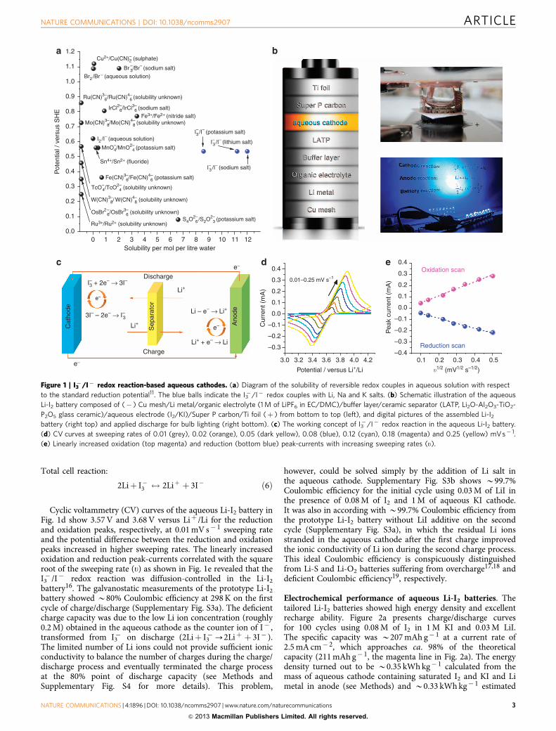
A promising aqueous cathode can be determined from theredox couples possessing high solubility and a suitable redoxpotential avoiding the electrolysis of water. The solubility isproportional to the energy density. In the diagram of redoxcouple solubility with respect to the standard reduction potential(Fig. 1a) (ref. 11), the triiodide/iodide (I3
� /I� ) redox couplereaction shows a favourable solubility (over 8 mol l� 1). Theredox potential of the I3
� /I� couples (0.536 V versus standardhydrogen electrode (SHE)) is also suitable to avoid waterelectrolysis. Therefore, in this work for the first time, wepresent the aqueous cathode operated by the I3
� /I� redoxcouples and apply this for a lithium-iodine (Li-I2) battery. Theaqueous Li-I2 battery we demonstrate is noticeably different fromeither the conventional all-solid-state or non-aqueous electrolyte-based Li-I2 batteries, which have performed at extremely lowdischarge current rate or shown low Coulombic efficiency withthe formation of a lithium iodide (LiI) layer12,13. The I3
� /I�
redox reaction in aqueous cathode is rapid and performed up12 mA cm� 2 of discharge current rate without serious potentialdrop. The aqueous Li-I2 battery attains superior storage capacity
(B98% of the theoretical capacity), Coulombic efficiency(499.5%), and cyclic performance (499.5% capacity retentionfor 100 cycles) which is, to the best of our knowledge, the bestresult among previous reports using new chemistries and systemconfigurations. The energy density reaches B0.33 kWh kg� 1,which is higher than that achieved in the conventionalbatteries.
ResultsI3� /I� redox reaction in aqueous cathode of Li-I2 batteries.
The I3� /I� redox reaction ideally occurs at 0.536 V versus
SHE (Fig. 1a) via two-electron transfer like the followingelectrochemical equation (1).
I�3 þ 2e� $ 3I� ; Eo¼ 0:536 V versus SHE ð1Þ
By using an aqueous half-cell of 1 M of KI solution, the for-mation of I3
� (brown) by the oxidation of I� (transparent) andits reverse reaction could be confirmed via the colour change ofelectrolyte on a glassy carbon (GC) electrode (see Methods andSupplementary Fig. S1), which occurred around 0.57 and 0.49 Vversus SHE.
The I3� /I� redox-couple-based aqueous cathode was
prepared with 1 M of aqueous KI by the addition of I2 to adjustthe I3
� concentration. The solubility of I2 is reasonablyhigh in the presence of alkaline iodide, which predominantlytransforms I2 to I3
� according to the following chemicalequation (2) (ref. 14)
I2ðsÞþ I� $ I�3 ; K ¼ 723�10 ð2Þ
where K is the equilibrium constant. From this, it is estimatedthat there is B0.1 M of I3
� in the given mixture of 0.1 M of I2 and1 M of aqueous KI. The potential of I3
� /I� redox reaction can becalculated by Nernst equation (3):
E¼ E0� RTnF
lnaI �
aI �3
ð3Þ
where E is the redox reaction potential, Eo is the standard cellpotential, R is the gas constant, T is the absolute temperature, n isthe number of moles of electrons transferred, F is the Faradayconstant, and aI �3 and aI � are the activity of I3
� and I� ,respectively. Assuming that the activity of I3
� and I� equals to itsconcentration, respectively, the redox reaction potential becomes0.508 V versus SHE in 0.1 M of I2 and 1 M of aqueous KI.
The I3� /I� aqueous cathode was directly used for the aqueous
Li-I2 battery. The aqueous Li-I2 batteries consist of Li anode(Cu mesh/Li metal/organic electrolyte/buffer layer), ceramicseparator, aqueous cathode, and current collector (Super P car-bon/Ti foil) as shown in Fig. 1b. Li metal with 1 M of LiPF6 inethylene carbonate (EC)/dimethyl carbonate (DMC) electrolytewas used for the anode. The Super P carbon-coated Ti foil wasemployed as the current collector in the aqueous cathode. Thewater-stable and Li ion conductive Li2O-Al2O3-TiO2-P2O5
(LATP) glass ceramic (see Supplementary Fig. S2 for the X-raydiffraction (XRD) pattern) separated the two electrodes andallowed only the Li ion to transfer across it15. The aqueous Li-I2
battery is operated as follows (Fig. 1c).Li anode:
Li$ Liþ þ e� ð4Þ
Aqueous cathode:
I�3 þ 2e� $ 3I� ð5Þ
ARTICLE NATURE COMMUNICATIONS | DOI: 10.1038/ncomms2907
2 NATURE COMMUNICATIONS | 4:1896 | DOI: 10.1038/ncomms2907 | www.nature.com/naturecommunications
& 2013 Macmillan Publishers Limited. All rights reserved.
Total cell reaction:
2Liþ I�3 $ 2Liþ þ 3I� ð6Þ
Cyclic voltammetry (CV) curves of the aqueous Li-I2 battery inFig. 1d show 3.57 V and 3.68 V versus Liþ /Li for the reductionand oxidation peaks, respectively, at 0.01 mV s� 1 sweeping rateand the potential difference between the reduction and oxidationpeaks increased in higher sweeping rates. The linearly increasedoxidation and reduction peak-currents correlated with the squareroot of the sweeping rate (u) as shown in Fig. 1e revealed that theI3� /I� redox reaction was diffusion-controlled in the Li-I2
battery16. The galvanostatic measurements of the prototype Li-I2
battery showed B80% Coulombic efficiency at 298 K on the firstcycle of charge/discharge (Supplementary Fig. S3a). The deficientcharge capacity was due to the low Li ion concentration (roughly0.2 M) obtained in the aqueous cathode as the counter ion of I� ,transformed from I3
� on discharge (2Liþ I3�-2Liþ þ 3I� ).
The limited number of Li ions could not provide sufficient ionicconductivity to balance the number of charges during the charge/discharge process and eventually terminated the charge processat the 80% point of discharge capacity (see Methods andSupplementary Fig. S4 for more details). This problem,
however, could be solved simply by the addition of Li salt inthe aqueous cathode. Supplementary Fig. S3b shows B99.7%Coulombic efficiency for the initial cycle using 0.03 M of LiI inthe presence of 0.08 M of I2 and 1 M of aqueous KI cathode.It was also in according with B99.7% Coulombic efficiency fromthe prototype Li-I2 battery without LiI additive on the secondcycle (Supplementary Fig. S3a), in which the residual Li ionsstranded in the aqueous cathode after the first charge improvedthe ionic conductivity of Li ion during the second charge process.This ideal Coulombic efficiency is conspicuously distinguishedfrom Li-S and Li-O2 batteries suffering from overcharge17,18 anddeficient Coulombic efficiency19, respectively.
Electrochemical performance of aqueous Li-I2 batteries. Thetailored Li-I2 batteries showed high energy density and excellentrecharge ability. Figure 2a presents charge/discharge curvesfor 100 cycles using 0.08 M of I2 in 1 M KI and 0.03 M LiI.The specific capacity was B207 mAh g� 1 at a current rate of2.5 mA cm� 2, which approaches ca. 98% of the theoreticalcapacity (211 mAh g� 1, the magenta line in Fig. 2a). The energydensity turned out to be B0.35 kWh kg� 1 calculated from themass of aqueous cathode containing saturated I2 and KI and Limetal in anode (see Methods) and B0.33 kWh kg� 1 estimated
3.0 3.2 3.4 3.6
Potential / versus Li+/Li
3.8 4.0 4.2
1.2
1.1
1.0
0.9
0.8
0.7
0.5
Pot
entia
l / v
ersu
s S
HE
0.6
0.4
0.3
0.2
0.1
0.00 1 2 3 4 5 6
Solubility per mol per litre water7 8 9 10 11 12
Ru3+/Ru2+ (solubility unknown)
OsBr2 –6/OsBr3–
6 (solubility unknown)S4O2–
6 /S2O2–3 (potassium salt)
I–3 /I– (potassium salt)+
–
I–3 /I– (lithium salt)
I–3 /I– (sodium salt)
I–3 + 2e– → 3I–
Discharge
3I– – 2e– → I–3
Li – e– → Li+
0.4
0.01–0.25 mV s–10.3
0.2
0.1
0.0
Cur
rent
(m
A)
–0.3
–0.2
–0.1
0.4Oxidation scan0.3
0.2
0.1
0.0
Pea
k cu
rren
t (m
A)
–0.3Reduction scan
–0.40.1 0.2
�1/2 (mV1/2 s–1/2)
0.3 0.4 0.5
–0.2
–0.1
e–
e–
Li+ + e– → Li
Li+
Charge
Sep
arat
or
Ano
de
Li+
Cat
hode
e–
e–
W(CN)3–8/ W(CN)4–
8 (solubility unknown)
TcO–4/TcO2–
4 (solubility unknown)
Fe(CN)3–6/Fe(CN)4–
6 (potassium salt)
Sn4+/Sn2+ (fluoride)
Cu2+/Cu(CN)–2 (sulphate)
Br –3/Br–
(sodium salt)
Br2 /Br – (aqueous solution)
IrCl2–6/IrCl3–
6 (sodium salt)Fe3+/Fe2+
(nitride salt)
Ru(CN)3–6/Ru(CN)4–
6 (solubility unknown)
Mo(CN)3–8/Mo(CN)4–
8 (solubility unknown)
MnO–4/MnO2–
4 (potassium salt)
I2 /I– (aqueous solution)
Figure 1 | I3�/I� redox reaction-based aqueous cathodes. (a) Diagram of the solubility of reversible redox couples in aqueous solution with respect
to the standard reduction potential11. The blue balls indicate the I3�/I� redox couples with Li, Na and K salts. (b) Schematic illustration of the aqueous
Li-I2 battery composed of (� ) Cu mesh/Li metal/organic electrolyte (1 M of LiPF6 in EC/DMC)/buffer layer/ceramic separator (LATP, Li2O-Al2O3-TiO2-
P2O5 glass ceramic)/aqueous electrode (I2/KI)/Super P carbon/Ti foil (þ ) from bottom to top (left), and digital pictures of the assembled Li-I2
battery (right top) and applied discharge for bulb lighting (right bottom). (c) The working concept of I3�/I� redox reaction in the aqueous Li-I2 battery.
(d) CV curves at sweeping rates of 0.01 (grey), 0.02 (orange), 0.05 (dark yellow), 0.08 (blue), 0.12 (cyan), 0.18 (magenta) and 0.25 (yellow) mVs� 1.
(e) Linearly increased oxidation (top magenta) and reduction (bottom blue) peak-currents with increasing sweeping rates (u).
NATURE COMMUNICATIONS | DOI: 10.1038/ncomms2907 ARTICLE
NATURE COMMUNICATIONS | 4:1896 | DOI: 10.1038/ncomms2907 | www.nature.com/naturecommunications 3
& 2013 Macmillan Publishers Limited. All rights reserved.

from the experimental result in I2 saturated Li-I2 battery(Supplementary Fig. S5), which is several times higherthan previously reported for alkaline aqueous cathodes9,10,20,redox-flow battery systems21 and other secondary batteries basedon aqueous electrolyte5,6,22. Furthermore, no significant capacityfading was observed during cycles. Figure 2b exhibits B99.6%capacity retention and 99.5� 100% Coulombic efficiency for 100cycles, which is superior to Li-S and Li-O2 batteries2, as wellas other aqueous Li batteries using a solid Ni(OH)2 cathode(95� 96% for 50 cycles)22, and aqueous cathodes comprisesFe3þ /Fe2þ redox reaction9 and Fe(CN)6
3� /Fe(CN)64�
(B98.6%) (ref. 10). The high capacity retention also sustained inhigh concentration, 1 M of I2 in the presence of 1 M KI, withB100% Coulombic efficiency for 20 cycles (SupplementaryFig. S6). The open circuit potential was B3.8 V versus Liþ /Liand the discharge and charge potentials were stable at 3.50 and3.70 V versus Liþ /Li on cycling, which resulted in overpotentials of0.04 and 0.16 V, respectively, from the thermodynamicallyreversible potential of I3
� /I� in the aqueous cathode (3.54 Vversus Liþ /Li). A larger overpotential on charge is due to the lowionic conductivity of LATP at a high current rate of 2.5 mA cm� 2.Nevertheless, the overpotential value at such a high current rateis still comparable to Li ion batteries23,24, and superior to Li-S(ref. 18) and Li-O2 (refs 19,25,26) batteries at current rates evenan order of magnitude lower, demonstrating B90% overall energyefficiency on cycling as shown in Supplementary Fig. S7.
Figure 2c shows a polarization graph recorded in the0.1� 12 mA cm� 2 range of current rates using 1 M of I2 and2 M of KI. The linear reduction in discharge potential withincreasing current rate (Supplementary Fig. S8) arose from thelarger internal resistance of the Li-I2 battery. The power densitycorrelated with the potential turned out to be B30 mW cm� 2 at10 mA cm� 2 current rate, which was more than three times higherthan the first aqueous cathode10 of Fe(CN)6
3� /Fe(CN)64� , and
twice that of its flow-through-mode system20. More importantly,the aqueous Li-I2 battery did not present any significant potentialdrop up to a current rate of 12 mA cm� 2, even though slightlyunsettled discharge potentials were observed over 5 mA cm� 2,which was notably different from the previous alkaline aqueouscathodes exhibiting a greater potential drop due to themass transport loss over 2.5 mA cm� 2 of current rate10,20.It was due to the fact that the suitable reduction potential ofI3� /I� suppresses a pronounced potential drop approaching to the
electrolysis potential of water, which would otherwise causedeterioration of the battery at high current rate. The power
density eventually approached B34.8 mW cm� 2 at 12 mA cm� 2
associated with a discharge potential of B2.9 V versus Liþ /Li.
DiscussionWe demonstrated reliable battery performance with high energydensity on cycles in aqueous Li-I2 battery. It was attributed to astable working potential window. The main redox reactionoccurred in the potential region of 3.5–3.7 V versus Liþ /Li thatwas converted to 0.46–0.66 V versus SHE. Although the potentialdrop/increase has been shown in the potential window of2.8–4.2 V versus Liþ /Li (� 0.24 to þ 1.16 V versus SHE) at theend of charge/discharge process the aqueous cathode containingthe excessive ionic concentration was electrochemically stable27
evidenced by neither H2 nor O2 evolution. The ceramic separatorof LATP, current collector and aqueous cathode were stable atthis operating condition. There was no significant structure andphase change of LATP on both sides communicating withthe organic (EC/DMC with Li salt in the anode side) and aqueous(I2/KI/LiI in the cathode side) electrolytes, confirmed by identicalXRD patterns before (Supplementary Fig. S2) and after 100 cycles(Fig. 3a). Nyquist plot using electrochemical impedancespectroscopy also revealed negligible decrease in ionic resistanceafter 100 cycles (Supplementary Fig. S9). The sturdy LATPceramic separator performed Li ion commute between anode andcathode on cycling. Inductively coupled plasma optical emissionspectrometry exhibited almost similar Li ion concentration in thefresh (27.7 mM) and 100-cycled (27.1 mM) aqueous electrodes(Fig. 3b). In addition, the current collector of Super P carbon/Tidid not deteriorate on cycling. We could not find any corrosionevidence of Ti foil by naked eye. Scanning electron microscopyimages in Fig. 3c,d and corresponding energy dispersivespectrometer analysis using transmission electron microscopy inSupplementary Fig. S10 revealed neither morphological changenor a precipitation layer on the Super P carbon. It was evidentthat the aqueous cathode was capable of sustaining over 100cycles with the LATP separator and current collector. Indeed, theaqueous Li-I2 battery constructed with the aqueous cathodecollected from the 100-cycled battery displayed comparableperformance to the fresh one. This rebuilt battery delivered acapacity of B200 mAh g� 1 (Fig. 3e) and 499.5% Coulombicefficiency for 50 cycles without any significant capacity fading(Fig. 3f).
By using the I3� /I� redox couples, the aqueous Li-I2 battery
has several advantages to achieve a reliable clean-energy storage
4.5
Specific capacity (mAhg–1)
0 50 100 150
Theoretical
200
Pot
entia
l (V
) ve
rsus
Li+
/Li
Cou
lom
bic
effic
ienc
y / %
Pot
entia
l (V
) ve
rsus
Li+
/Li
3.5
4.0
3.0
2.50.0 0.2 0.4 0.6 0.8 1.0
Cycle no. Time per 1,000 s
0 20 40 60 80 100 0 2 4 6 8 10 12
2.93.0
Current density (mAcm–2)
2.8
3.0
3.2
3.4
3.6
25034.8
30.2
40
32
24
16
8
0Spe
cific
cap
acity
(m
Ahg
–1)
Pow
er d
ensi
ty (
mW
cm–2
)
200
150
100
50
0
3.8
0.25
12107.5
53210.75
0.5
0.1
97
98
99
100
101
ChargeDischarge
102
Normalized capacity
Figure 2 | Electrochemical performance of aqueous Li-I2 batteries. (a) Hundred-times cycled charge/discharge profile at a current rate of
2.5 mA cm� 2 using 0.08 M of I2 in the presence of 1 M of KI and 0.03 M of LiI. The magenta dashed curve indicates the theoretical discharge profile.
(b) Cyclic performance presenting Coulombic efficiency and specific capacity upon charge/discharge cycles. (c) Polarization graph presenting
discharge potential (black circle) and corresponding power density (blue triangle) at current rates ranging from 0.1 to 12 mA cm� 2 in 1 M of I2and 2 M of KI.
ARTICLE NATURE COMMUNICATIONS | DOI: 10.1038/ncomms2907
4 NATURE COMMUNICATIONS | 4:1896 | DOI: 10.1038/ncomms2907 | www.nature.com/naturecommunications
& 2013 Macmillan Publishers Limited. All rights reserved.

system. The I2/KI aqueous electrolyte provides near-neutral pH(B6.3 in the as-prepared electrolyte, B7.2 in both I2 and KI thesaturated electrolyte), which removes the concern for degradationof the ceramic separator10 and additional chemical treatment tofacilitate redox reactions on the working system9. The aqueous KIenables the aqueous Li-I2 battery to be scaled up with a low costby eliminating the costly organic electrolyte and Li salts in thecathode. Besides, I2/KI electrolyte is non-flammable and heavy-metal free. In addition, again, the aqueous cathode containing theI3� /I� redox couples does not leave any solid product, which
leads to no volume expansion and promotes adequate rechargeability. The redox reaction potential is also suitable for use inaqueous solution, thereby rendering no deterioration of thebattery at high current rate despite the cooperation with low ionicconductivity of LATP ceramic separator. Therefore, the aqueouscathode using the I3
� /I� redox couples shows great promise toconstitute the new generation of energy storage system to satisfyboth high energy density and low environmental impact, andcould be suitably scaled up subsequent to development of aceramic separator with higher mechanical strength.
In summary, the I3� /I� redox reaction-operated aqueous Li-I2
battery exhibited excellent cyclic performance with considerableenergy and power densities. Ideal Coulombic efficiency andcapacity retention with no degradation of cathode establish theaqueous Li-I2 battery as one of the outstanding post Li batteries.The specific energy density (B0.33 kWh kg� 1) is fairly promis-ing in comparison to the conventional lead-acid, nickel-metalhydride and Li ion batteries, and can be further improved tobe B0.4 kWh kg� 1 using NaI or LiI instead of aqueous KI asreferred to the solubility diagram in Fig. 1a. The aqueous cathodesystem can be also extendable to aqueous Na-I2 and K-I2
batteries. We believe that this energy storage system can be scaledup with a reasonably increased energy density by combining aflow-through-mode system.
MethodsPreparation of aqueous Li-I2 batteries. The preparation and assembly of theanode side were conducted in an Ar-filled glove box (o1 p.p.m. of H2O and O2,Kiyon). A thin and flat Li metal (Honjo) attached to a copper (Cu) mesh (NilacoCorporation, 100 mesh) was set on a cylindrical glass shell. A polymer buffer layer(Celgard 2500, received from Celgard) was inserted between the Li metal and LATPto impede the formation of a highly resistive precipitation layer from the ceramicseparator28. An organic electrolyte of 1 M LiPF6 (Aldrich) in ethylene carbonate(EC, Kishida Chemicals)/dimethyl carbonate (DMC, Kishida Chemicals) withvolume ratio 3:7 was added into this glass cylinder. LATP (Li2O-Al2O3-TiO2-P2O5)glass ceramic separator (Ohara Corporation, B180±20mm in thickness) was fixedon top of the glass cylinder thus sealing in the anode. To prepare the currentcollector and aqueous cathode, Super P carbon (received from Timcal) and apolyvinylidene fluoride binder (PVDF, received from Kynar) were mixed with inan 80:20 mass ratio in N-methyl-2-pyrrolidone. This carbon slurry was cast on atitanium (Ti) foil (99.5% of purity, Nilaco Corporation, 40 mm in thickness) with aloading density of 1 mg cm� 2
carbon and dried at 115 �C for 12 h in air to removeany residual solvent. The current collector of Super P carbon-loaded Ti foil wasstuck on the other cylindrical shape of the glass shell, in which the aqueous cathodecontaining I2 (99%, Wako Chemicals), KI (99.5%, Wako Chemicals), and LiI(99.9%, Wako Chemicals) was added with a total volume of 150 ml, which was thensealed with the backside of the LATP employed in the anode assembly.The completed battery had a configuration of (� ) Cu mesh/Li metal/organicelectrolyte/buffer layer/LATP/aqueous cathode/Super P carbon/Ti foil (þ )(Fig. 1b). The geometric areas of the current collector and the ceramicseparator were B0.2 cm2 (5 mm in diameter) and 0.5 cm2 (8 mm in diameter),respectively.
Electrochemical measurements. The I3� /I� electrochemical reaction was
investigated using a potentiostatic method of CV and a galvanostatic methodof charge/discharge curve at room temperature in 1 atm using a battery cycler(WBCS3000, WonATech). The CV curves of the aqueous Li-I2 batteries wererecorded at sweeping rates from 0.01 to 0.25 mV s� 1 in the potential range from3.04 to 4.24 V versus Liþ /Li. The battery performance was carried out at 2.8 and4.2 V versus Liþ /Li for the cutoff discharge and charge potential, respectively.The current rate estimated from the applied current with the geometrical areaof current collector was from 0.1 to 12 mA cm� 2. The capacity was calculatedfrom the mass of active species of I2, for example, ca. 3 mg from 0.08 M ofI2 in 150 ml of total aqueous cathode.
I3�/I� redox reaction. The I3
� /I� redox reaction was investigated via poten-tiostatic mode (VMP3, Biologic). The CV was examined in a half-cell of 1 M KI at asweeping rate of 10 mV s� 1. A polished GC was used as the working electrodewith a Pt wire as the counter electrode, and a saturated calomel electrode as thereference electrode. Supplementary Fig. S1 shows the optical images of GCelectrode surface in 1 M aqueous KI and with the corresponding CV curve.From open circuit potential (OCP, B0.12 V), the curve was swept from (1)negative (black), (2)—(3) positive (blue) and (4)—(5) negative (black) potentialdirection in the potential range from 0.1 to 0.8 V. The oxidation reaction(3I�-I3
� þ 2e� ) was observed from B0.32 V by the CV curve and the elec-trolyte colour on the GC surface changed from transparent (I� ) to brown (I3
� ).The I3
� formed during (3)—(4) sweeping diffused out from the GC surface. Dis-appearance of I3
� close to the GC surface could be observed at B0.25 V due to thereduction reaction (I3
� þ 2e�-3I� ). The reduction and oxidation reactions,therefore, occurred B0.494 and B0.564 V versus SHE, presenting somewhatthe resistive behaviour from the thermodynamically reversible potential(0.536 V versus SHE).
Diffusion-controlled behaviour in aqueous Li-I2 batteries. SupplementaryFig. S4 shows quantitatively simulated diffusion-controlled charge/discharge
3.0 195
190
185
180
175
Cathode sideAnode side
ChargeDischarge
2.5
2.0
1.5
1.0
0.5
0.0
10 20 30 40 50 60 70Fr
esh
Cycled
2� (deg.)
Normalized capacity
Specific capacity (mAh g–1)
Cycle no.
0.02.5
3.0
Pot
entia
l (V
) ve
rsus
Li+
/Li
Cou
lom
bic
effic
ienc
y (%
)
3.5
4.0
4.50 50 100 150 200
0.2 0.4 0.6 0.8 1.097
98
99
100
101
102
103
0 10 20 30 40 50
Inte
nsity
(10
3 c.p
.s.)
Li+ c
once
ntra
tion
(mg
l–1)
Li+ c
once
ntra
tion
(mm
ol l–1
)29
28
27
26
25
Nor
mal
ized
cap
acity
1.2
1.0
0.8
0.6
0.4
0.2
0.0
5.0kV 8.4 mm x200k SE(U) 200 nm 200 nm5.0kV 8.2 mm x200k SE(U)
Figure 3 | Analyses of 100-times cycled aqueous Li-I2 batteries and
their post electrochemical performance. (a) XRD patterns of LATP
communicating with anode (magenta) and cathode (black) electrolytes for
100 cycles. (b) Inductively coupled plasma optical emission spectrometry
analysis of Li ion concentration. The Li ion concentration was 188 and
192 mg l� 1 (black column) or 27.1 and 27.7 mM (blue column) for the fresh
and 100-cycled aqueous electrodes, respectively. Scanning electron
microscopy images of Super P carbon before (c) and after (d) 100 cycles.
Scale bars, 200 nm. Charge/discharge profile (e) and cyclic performance
(f) upon 50 cycles from the battery constructed from 100-cycled aqueous
electrode (I2/KI/LiI with 0.08/1/0.03 M).
NATURE COMMUNICATIONS | DOI: 10.1038/ncomms2907 ARTICLE
NATURE COMMUNICATIONS | 4:1896 | DOI: 10.1038/ncomms2907 | www.nature.com/naturecommunications 5
& 2013 Macmillan Publishers Limited. All rights reserved.

behaviour of the prototype Li-I2 battery (the first cycle of Supplementary Fig. S3a)in terms of the ionic conductivities of LATP (s(LATP), 10� 3� 10� 4 S cm� 1)(http://www.ohara-inc.co.jp/en/product/electronics/licgc.html#04), Li ion (s(Liþ ))(ref. 29), I� (s(I� )) (ref. 29), I3
� (s(I3� )) (ref. 30), organic electrolyte (s(organic)
from 1 M LiPF6 in EC/DMC in the anode side, E1.1� 10� 2 S cm� 1) (ref. 31) andthe applied current rate (s(J)). The s(J) (olive solid line) at a current density of2.5 mA cm� 2 was estimated from the charge/discharge profile in SupplementaryFig. S3a according to equations (equations 7 and 8):
Discharge:
sðJÞdischarge ¼J � l
Edischargeð7Þ
Charge:
sðJÞcharge ¼J � l
Echarge � ½E0 � RTnF ln aI�
aI�3
� ��
ð8Þ
where J was the current rate (2.5 mA cm� 2), l was the distance between anode andcathode (3 mm), Edischarge was the discharge potential, Echarge was the chargepotential, and Eo, R, T, n, F, aI �3 and aI � are identical to Nernst equation(equation 3). The s(organic) (black dashed line) and s(I� ) (white solid line) werea few orders of magnitude higher than the others due to the high concentration andthus were not involved in the termination of discharge and charge process. Thetypical s(LATP) (blue dashed line) obtained from Li ion diffusion in the LATP washigher than s(J) on discharge, which contributed to smooth mass transport of Liions from the anode to the aqueous cathode. The discharge capacity was pre-dominantly governed by the I3
� concentration through the I3� /I� redox reaction
(2Liþ I�3 ! 2Liþ þ 3I� ). The s(I3� ) (pink solid line) steeply decreased at the end
of discharge and eventually reached s(J) as marked by the black square. Thenormalized discharge capacity was B0.97, which was consistent with the experi-mentally obtained capacity of B0.98 (normalized). Upon charge, abundant I�
ions (s(I� )) in aqueous KI did not contribute to the termination of the chargeprocess. Instead, s(Liþ ) (orange solid line) determined the termination by closelyreaching s(J). The limited Li ion concentration (roughly 0.2 M) in the aqueouscathode as the counter ion of I� transformed from I3
� could not provide sufficientionic conductivity to retain the charge process up to the same capacity of discharge.It was also probably related to the high resistance of LATP to migration of Li ionsfrom the aqueous cathode to the anode. The normalized capacity of B0.79 wasdeduced as indicated by the black square, which was comparable to the experi-mentally obtained value of B0.80 (normalized). With regard to the diagram shownin Supplementary Fig. S4, several methods can be proposed to increase Coulombicefficiency. The first one is to increase the concentration of Li ion or I2 in theaqueous electrode, which can increase the s(Liþ ) and retain the charge processfurther. The second is to decrease the applied current rate (J) during charge.Optimized electrode design such as shortening the I3
� or Li ion diffusion distance(l) would also be beneficial. Among them, the addition of Li salt in the aqueouscathode is the simplest route to increase the Coulombic efficiency while main-taining the existing battery performance. It is evidenced by B100% Coulombicefficiency on the second cycled battery (Supplementary Fig. S3a), in which theresidual Li ions stranded in the aqueous cathode after the first charge increased Liion conductivity. The additional Li salt in the fresh aqueous cathode improvedCoulombic efficiency at the initial cycle. Supplementary Fig. S3b shows B99.7%Coulombic efficiency by adding 0.03 M of LiI in the presence of 0.08 M of I2 and1 M of KI.
Estimation of energy density. Energy density of the aqueous Li-I2 battery basedon the total weight of the aqueous cathode and Li metal anode can be estimatedfrom equation (9):
ED¼ Erev � Q �mI2
Manodeþ cathode¼ Erev � Q �mI2
ðmLiÞanode þðmI2 þmXI þmH2 OÞcathode
ð9Þ
where ED is the energy density (kWh kg� 1), Erev (V) is the reversible potential(3.576 V versus Liþ /Li), Q is the theoretical capacity of I2 (211 Ah kg� 1), andManodeþ cathode (kg) is the total mass of Li metal anode (mLi) and aqueous cathode,which is itself the sum of the mass of I2 (mI2
), alkali iodide (mXI, X¼K, Li or Na) andwater (mH2O). Considering the high solubility (B8.5 mol l� 1) of I3
� /I� (Fig. 1a)and I2 in aqueous KI (equation 2), mI2
, mXI and mLi is 2.16, 1.41 and 0.118 kg,respectively, in the given 1 kg of aqueous solution (mH2O) at 298 K. The specificenergy density values were thus estimated to be 0.35 kWh kg� 1 or 0.70 kWh l� 1
(mass density at 298 K: B2 kg l� 1). The estimated value is consistent with theexperimental result of 0.33 kWh kg� 1 (Supplementary Fig. S5). When usingLiI or NaI instead of KI, mI2
, mXI and mLi were 2.84, 1.50 and 0.16 kg for LiI,and 3.05, 1.80 and 0.17 kg for NaI, respectively. The specific energy densityvalues were thus estimated to be 0.39 kWh kg� 1 for LiI and 0.38 kWh kg� 1
for NaI, respectively.
Characterizations. XRD patterns were attained from a parallel beam XRDinstrument (Smartlab, lCuKa¼ 1.542 Å, Rigaku). Inductively coupled plasmaoptical emission spectrometry characterization was performed on a Varian 720-ES.
Scanning electron microscopy observation was performed on a Hitachi S-4800T.Transmission electron microscopy and energy dispersive spectrometer analysis wasperformed on a JEOL JEM-2100F.
References1. Choi, N.-S. et al. Challenges facing lithium batteries and electrical double-layer
capacitors. Angew. Chem., Int. Ed. 51, 9994–10024 (2012).2. Bruce, P. G., Freunberger, S. A., Hardwick, L. J. & Tarascon, J.-M.
Li–O2 and Li–S batteries with high energy storage. Nat. Mater. 11, 19–29(2012).
3. Ryan, K. R., Trahey, L., Ingram, B. J. & Burrell, A. K. Limited stabilityof ether-based solvents in lithium-oxygen batteries. J. Phys. Chem. C 116,19724–19728 (2012).
4. Meini, S., Piana, M., Beyer, H., Schwammlein, J. & Gasteiger, H. A. Effect ofcarbon surface area on first discharge capacity of Li-O2 cathodes and cycle-lifebehavior in ether-based electrolytes. J. Electrochem. Soc. 159, A2135–A2142(2012).
5. Li, W., Dahn, J. R. & Wainwright, D. Rechargeable lithium batteries withaqueous electrolytes. Science 264, 1115–1118 (1994).
6. Luo, J.-Y., Cui, W.-J., He, P. & Xia, Y.-Y. Raising the cycling stability of aqueouslithium-ion batteries by eliminating oxygen in the electrolyte. Nat. Chem. 2,760–765 (2010).
7. Wang, H. et al. An ultrafast nickel-iron battery from strongly coupledinorganic nanoparticle/nanocarbon hybrid materials. Nat. Commun. 3, 917(2012).
8. Pasta, M., Wessells, C. D., Huggins, R. A. & Cui, Y. A high-rate and long cyclelife aqueous electrolyte battery for grid-scale energy storage. Nat. Commun. 3,1149 (2012).
9. Wang, Y., Wang, Y. & Zhou, H. A Li–liquid cathode battery based on a hybridelectrolyte. Chem. Sus. Chem 4, 1087–1090 (2011).
10. Lu, Y., Goodenough, J. B. & Kim, Y. Aqueous cathode for next-generationalkali-ion batteries. J. Am. Chem. Soc. 133, 5756–5759 (2011).
11. Dean, J. A. Lange’s Chemistry Handbook 14th edn (McGraw-Hill ProfessionalPublishing, 1992).
12. Owen, J. R. Rechargeable lithium batteries. Chem. Soc. Rev. 26, 259–267 (1997).13. Schmidt, C. L. & Skarstad, P. M. Development of an equivalent-circuit
model for the lithium/iodine battery. J. Power Sources 65,121–128 (1997).
14. Svensson, P. H. & Kloo, L. Synthesis, structure, and bonding in polyiodide andmetal iodide� iodine systems. Chem. Rev. 103, 1649–1684 (2003).
15. Adachi, G., Imanaka, N. & Aono, H. Fast Liþ conducting ceramic electrolytes.Adv. Mater. 8, 127–135 (1996).
16. Wang, Y. L., Sun, Q. L., Zhao, Q. Q., Cao, J. S. & Ye, S. H. Rechargeablelithium/iodine battery with superior high-rate capability by usingiodine-carbon composite as cathode. Energy Environ. Sci. 4,3947–3950 (2011).
17. Ji, X. & Nazar, L. F. Advances in Li-S batteries. J. Mater. Chem. 20, 9821–9826(2010).
18. Schuster, J. et al. Spherical ordered mesoporous carbon nanoparticles with highporosity for lithium-sulfur batteries. Angew. Chem. Int. Ed. 51, 3591–3595(2012).
19. Black, R. et al. Screening for superoxide reactivity in Li-O2 battereis:effect on Li2O2/LiOH crystallization. J. Am. Chem. Soc. 134,2902–2905 (2012).
20. Lu, Y. & Goodenough, J. B. Rechargeable alkali-ion cathode-flow battery.J. Mater. Chem. 21, 10113–10117 (2011).
21. Dunn, B., Kamath, H. & Tarascon, J.-M. Electrical energy storage for the grid: abattery of choices. Science 334, 928–935 (2011).
22. Li, H., Wang, Y., Na, H., Liu, H. & Zhou, H. Rechargeable Ni-Li batteryintegrated aqueous/nonaqueous system. J. Am. Chem. Soc. 131, 15098–15099(2009).
23. Recham, N. et al. A 3.6 V lithium-based fluorosulphate insertionpositive electrode for lithium-ion batteries. Nat. Mater. 9,68–74 (2010).
24. Whittingham, M. S. Lithium batteries and cathode materials. Chem. Rev. 104,4271–4302 (2004).
25. Freunberger, S. A. et al. The lithium–oxygen battery with ether–basedelectrolytes. Angew. Chem. Int. Ed. 50, 8609–8613 (2011).
26. Lim, H., Yilmaz, E. & Byon, H. R. Real-time XRD studies of Li-O2
electrochemical reaction in nonaqueous lithium-oxygen battery. J. Phys. Chem.Lett. 3, 3210–3215 (2012).
27. Wessells, C., Ruffo, R., Huggins, R. A. & Cui, Y. Investigations of theelectrochemical stability of aqueous electrolytes for lithium battery applications.Electrochem. Solid St. 13, A59–A61 (2010).
28. Zhang, T. et al. Li/polymer electrolyte/water stable lithium-conducting glassceramics composite for lithium-air secondary batteries with an aqueouselectrolyte. J. Electrochem. Soc. 155, A965–A969 (2008).
ARTICLE NATURE COMMUNICATIONS | DOI: 10.1038/ncomms2907
6 NATURE COMMUNICATIONS | 4:1896 | DOI: 10.1038/ncomms2907 | www.nature.com/naturecommunications
& 2013 Macmillan Publishers Limited. All rights reserved.

29. Lide, D. R. CRC Handbook of Chemistry and Physics 3rd edn (CRC Press, Inc.,2000).
30. Kolthoff, I. M. & Jordan, J. Voltammetry of iodine and iodide at rotatedplatinum wire electrodes. J. Am. Chem. Soc. 75, 1571–1575 (1953).
31. Xu, K. Nonaqueous liquid electrolytes for lithium-based rechargeable batteries.Chem. Rev. 104, 4303–4418 (2005).
AcknowledgementsWe gratefully acknowledge the financial support from RIKEN.
Author contributionsY.Z. and H.R.B. conceived and designed the experiments and co-wrote the paper. Y.Z.designed the battery and performed the experiments. L.W. participated in the experiment
measurement and data analysis. Y.Z. is thankful to RIKEN materials characterizationteam for their support on transmission electron microscopy operation.
Additional informationSupplementary Information accompanies this paper at http://www.nature.com/naturecommunications.
Competing financial interests: The authors declare no competing financial interest.
Reprints and permission information is available online at http://npg.nature.com/reprintsandpermissions/
How to cite this article: Zhao, Y. et al. High-performance rechargeable lithium-iodinebatteries using triiodide/iodide redox couples in an aqueous cathode. Nat. Commun.4:1896 doi: 10.1038/ncomms2907 (2013).
NATURE COMMUNICATIONS | DOI: 10.1038/ncomms2907 ARTICLE
NATURE COMMUNICATIONS | 4:1896 | DOI: 10.1038/ncomms2907 | www.nature.com/naturecommunications 7
& 2013 Macmillan Publishers Limited. All rights reserved.