high power factor pwm converter - fuji electric europe · 2017-04-12 · instruction manual high...
TRANSCRIPT

Instruction Manual
High Power Factor PWM Converterwith Power Regenerative Function (Stack Type)
RHC-D SeriesRHC132S-4DE to RHC315S-4DERHC630B-4DE to RHC800B-4DE
• Read through this instruction manual to become familiar with the handling procedure of this product, and proceed to installation, connection (wiring), operation, and maintenance inspection.
• Deliver this manual to the end user of this product. Keep this manual in a safe place until this product is discarded.• The product is subject to change without prior notice.
Fuji Electric Co., Ltd. INR-SI47-1722c-E

Copyright © 2014Fuji Electric Co., Ltd.All rights reserved.No part of this publication may be reproduced or copied without prior written permission from Fuji Electric Co., Ltd.
All products and company names mentioned in this manual are trademarks or registered trademarks of their respective holders.
The information contained herein is subject to change without prior notice for improvement.

i
Safety PrecautionsRead the safety precautions thoroughly for safe use of the product and become familiar with correct use before handling the product.
Safety precautions are classified into the following four categories in this manual: WARNING, CAUTION and NOTE.
Failure to heed the information indicated by this symbol may lead to dangerous conditions, possibly resulting in death or serious bodily injuries.
Failure to heed the information indicated by this symbol may lead to dangerous conditions,possibly resulting in minor or light bodily injuries and/or substantial property damage.
NOTEOffers important information for your under-standing and handling of the product.
WARNING and CAUTION are given in Safety Precautions and the section where injury or damage is anticipated. NOTE is given only in the section that requires additional information.
Failure to heed the information, even though its symbol is , may cause serious results depending on the situation. Since all WARNING and CAUTION contain important factors, always observe their precautions.
The converter system is used to drive machinery in various places, so it is impossible to anticipate all the situations where troubles will be caused by potential factors. Therefore, observe also the safety precautions needed for inverters, motors, equipment, and the places of use.
Remarks:- Serious bodily injuries include loss of eyesight,
injury, burn (hot or cold), electric shock, fracture of a bone, poisoning or the like. All of these cause aftereffect and require hospitalization or attendance at the hospital for a long term for cure.
- Minor and medium injuries indicate burns and electric shock that does not require hospitalization or long-term visiting care.
- Damage to the property means enlargement loss concerning breakage of property and damage to the equipment.
• Peripheral devices such as the filter stack, filtering resistors and reactors, and boosting reactors as well as the heat sink become hot. NEVER touch these devices while the power is ON and immediately after the power is turned OFF until they cool down.Burns and injuries may result.
• Mount the front cover or the like without fail on the peripheral devices to keep them away from the reach of people.Electric shock or injury may result.

ii
Application
• The PWM converter is intended for use in combination with a Fuji inverter that drives a three-phase induction motor, and must not be used for any other purposes.Fire could result.
• The PWM converter may not be used for a life-support system or other purposes directly related to the human safety.
• Though the product is manufactured under strict quality control, install safety devices for applications where serious accidents or property damages are foreseen in relation to the failure of it.An accident could occur.
Installation
• Mount the converter on a base made of metal or other non-flammable material.Otherwise, a fire could occur.
• Do not place flammable material nearby.Doing so could cause fire.
• Install the converter in an inaccessible place, e.g., in a control panel.Otherwise, electric shock or injuries could occur.
• Do not support the converter by its front cover during transportation.Doing so could cause a drop of the converter and injuries.
• Prevent lint, paper fibers, sawdust, dust, metallic chips, or other foreign materials from getting into the converter or from accumulating on the heat sink.Otherwise, a fire or an accident might result.
• Do not install or run a converter that is damaged or lacking parts.Doing so could cause injuries.
• When changing the positions of the mounting bases, use the attached screws.Otherwise, injuries could occur.

iii
Wiring
• When wiring the converter to the power source, insert a recommended molded case circuit breaker (MCCB) or residual-current-operated protective device (RCD)/earth leakage circuit breaker (ELCB) in the path of each pair of power lines to the converter.Otherwise, a fire could occur.
• Use the peripheral devices authorized by Fuji Electric for the converter.Otherwise, a fire or bodily injuries could occur.
• Use wires in the specified size.Otherwise, a fire could occur.
• Be sure to ground the converter's grounding terminals.Otherwise, electric shock or fire could occur.
• Qualified electricians should carry out wiring.Otherwise, an electric shock could occur.
• Ensure that the power is turned OFF (open circuit) before starting wiring.Otherwise, an electric shock could occur.
• Be sure to complete installation of the converter before wiring.Otherwise, an electric shock or injuries could occur.
• Never supply power to a converter whose parts are broken or coming off, or to a converter damaged in transportation.Doing so could cause an electric shock or fire.
• Never connect a DC reactor to the converter.Doing so could cause a fire.
• Ensure that the number of input phases and the rated voltage of the product match the number of phases and the voltage of the AC power supply to which the product is to be connected.Otherwise, injuries could occur.
• Ensure that the polarity of the converter’s DC terminals (P(+) and N(-)) match that of the inverter’s ones.Otherwise, an accident could occur.
• The converter, filter stack, inverter, motor and wiring generate electric noise. Be careful about malfunction of the nearby sensors and devices. To prevent them from malfunctioning, implement noise control measures.Otherwise, an accident could occur.
Operation
• Be sure to mount the front cover before turning the power ON. Do not remove the cover when the converter power is ON.An electric shock could occur.
• Do not operate switches with wet hands.Doing so could cause electric shock.
• Confirm that the Run signal is OFF before resetting an alarm. Resetting an alarm with the Run signal being ON may cause a sudden motor start.An accident could occur.
• Never touch the terminals when the power is supplied to the converter, filter stack or peripheral devices even if the converter is stopped.An electric shock could occur.

iv
• Do not touch the heat sink, filtering resistors, filtering reactors or boosting reactors because they become hot.Burns may result.
Maintenance and inspection, and parts replacement
• Before proceeding to the maintenance/inspection, turn the power OFF, make sure that the charging lamp is turned OFF. Further, make sure that the DC voltage across the terminals P(+) and N(-) and the terminal voltage of the filtering capacitor is +25VDC or below.Otherwise, an electric shock could occur.
• Maintenance, inspection, and parts replacement should be made only by qualified persons.• Take off the watch, rings and other metallic objects before starting work.• Use insulated tools.
Otherwise, an electric shock or injuries could occur.
Disposal
• Treat the product as an industrial waste when disposing of it.Otherwise, injuries could occur.
Others
• Never attempt to modify the product.Doing so could cause an electric shock or injuries.

PrefaceThank you for purchasing our PWM converter "RHC-D series." This product is intended for use in combination with a Fuji inverter (see the table below) as a bidirectional device for converting AC current to DC current and vice versa. Read through this instruction manual to become familiar with the handling procedure for correct use. Improper handling might result in incorrect operation, a short life, a failure of this product, or even substantial property damage. Even after reading this manual, read it again and again whenever necessary. For this purpose, keep this manual handy so that the user can refer to it any time.
If there is anything that you do not understand about the product or this instruction manual, contact the store you purchased or your nearest Fuji sales representative. This instruction manual does not contain the information on how to handle inverters. For the information, refer to the inverter instruction manual.
List of applicable inverters
The table below lists the inverters that can be used in combination with this product. The unit type and stack type of inverters can be used.
Inverter series Capacity Inverter type Stack/unit type
VG series All capacities FRN VG1S-4 FRN SVG1S-4 (*1) FRN BVG1S-4 (*1)
Unit type/stack type
MEGA series All capacities FRN G1S-4 (*1) Unit type
Ace series All capacities FRN E2S-4 (*1) Unit type
Eco series All capacities FRN F1S-4 (*1) Unit type
(*1) Contact Fuji Electric if using the combination.

1. Outline ................................................... 1-1 2. Before Use ............................................. 2-1
2.1 Acceptance Inspection .................. 2-1 2.2 Appearance of the Product ............ 2-3 2.3 Handling the Product ..................... 2-5 2.4 Transportation ............................... 2-6 2.5 Storage .......................................... 2-6
3. Installation and Connection ................... 3-1
3.1 Operating Environment ................. 3-1 3.2 Installation and Layout .................. 3-2 3.3 Connection .................................... 3-6 3.3.1 General precautions about connection .......................... 3-4 3.3.2 Terminal Function ......................... 3-7 3.3.3 Terminal Layout Drawing .............. 3-9 3.3.4 Basic Connection Diagram ........... 3-14 3.3.5 Details of Connection ................... 3-17 3.3.6 Precautions for Installation ........... 3-29 3.3.7 Tightening torque and wire size for devices applicable to the main circuit ..... 3-30 3.3.8 Peripheral Devices ....................... 3-32 3.3.9 Connecting Optional Devices ....... 3-34
4. Preparation for Operation ...................... 4-1
4.1 Inspection and Preparation ........... 4-1 4.2 Driving Method .............................. 4-1 4.3 Test Run ........................................ 4-1
5. Operation Using the Keypad ................. 5-1
5.1 Appearance ................................... 5-1 5.2 Operation and Display Screen ...... 5-2 5.2.1 Screen Immediately After Auxiliary Control Power Supply IsTurned On ........ 5-2 5.2.2 Screen immediately after the main circuit power supply is turned on .. 5-3 5.2.3 Switching LED monitor screens ... 5-4 5.2.4 Switching LCD screens ................ 5-5 5.2.5 Configuring function code data ..... 5-6 5.2.6 Checking function code settings .. 5-9 5.2.7 Monitoring the running status ....... 5-10 5.2.8 Checking I/O signal states ............ 5-11 5.2.9 Displaying maintenance information .................................. 5-12 5.2.10 Measuring load factor ................... 5-14 5.2.11 Displaying alarm information ........ 5-15 5.2.12 Displaying alarm history and cause .......................................... 5-17 5.2.13 Copying data ................................ 5-18
6. Description of Function Codes .............. 6-1
6.1 Function Code Tables .................... 6-1 6.2 Details of Function Codes ............. 6-2
7. Troubleshooting ..................................... 7-1
7.1 List of Protective Functions ........... 7-1 7.2 Error Reset .................................... 7-3 7.3 Troubleshooting ............................. 7-4 7.4 Converter Cannot Get Ready to Run ............................................ 7-13
8. Maintenance and Inspection ................. 8-1
8.1 Daily Inspection .............................. 8-1 8.2 Periodic Inspection ......................... 8-2 8.3 Measurement of Electrical Quantity in Main Circuit ............................... 8-4 8.4 Insulation Test ................................ 8-5 8.5 Replacement Parts ......................... 8-6 8.6 Inquiries about Product and Guarantee 8-6
Contents

9. Control Options ...................................... 9-1 9.1 Common Specifications ................. 9-1 9.1.1 Option list...................................... 9-1 9.1.2 Acceptance inspection ................. 9-1 9.1.3 Installing a built-in option (OPC-VG7) ................................... 9-2 9.2 T-Link Option ................................. 9-10 9.2.1 Product Overview ......................... 9-10 9.2.2 Model and specifications .............. 9-11 9.2.3 Specifications ............................... 9-11 9.2.4 External view ................................ 9-12 9.2.5 Basic Connection Diagram ........... 9-13 9.2.6 Function codes ............................. 9-15 9.2.7 Protective operation ..................... 9-15 9.3 SX Bus Option ............................... 9-16 9.3.1 Product Overview ......................... 9-16 9.3.2 Model and Specifications .............. 9-17 9.3.3 Specifications ............................... 9-17 9.3.4 External View ................................ 9-19 9.3.5 Basic Connection Diagram ........... 9-20 9.3.6 Function Codes ............................ 9-22 9.3.7 Protective Operation ..................... 9-23 9.4 CC-Link Option .............................. 9-24 9.4.1 Product Overview ......................... 9-24 9.4.2 Model and Specifications .............. 9-25 9.4.3 Specifications ............................... 9-25 9.4.4 External View ................................ 9-27 9.4.5 Basic Connection Diagram ........... 9-28 9.4.6 Protective Operation ..................... 9-29 9.5 DIO Option ..................................... 9-31 9.5.1 Outline of Product ......................... 9-31 9.5.2 Model and Specifications .............. 9-32 9.5.3 Specifications ............................... 9-32 9.5.4 Dimensioned Drawing .................. 9-33 9.5.5 Basic Connection Diagram ........... 9-35 9.5.6 Function Codes ............................ 9-36 9.5.7 Check Function ............................ 9-36 9.6 AIO Option ..................................... 9-37 9.6.1 Outline of Product ......................... 9-37 9.6.2 Model and Specifications .............. 9-38 9.6.3 Specifications ............................... 9-38 9.6.4 Dimensioned Drawing .................. 9-39 9.6.5 Basic Connection Diagram ........... 9-40 9.6.6 Function Codes ............................ 9-41 9.6.7 Check Function ............................ 9-41 9.7 SI Option ........................................ 9-42 9.7.1 Product Overview ......................... 9-42 9.7.2 Model ............................................ 9-42 9.7.3 Specifications ............................... 9-43 9.7.4 External drawings ......................... 9-44 9.7.5 Connection ................................... 9-45 9.7.6 Basic connection diagram ............ 9-49 9.7.7 Operation ...................................... 9-50 9.7.8 Protection functions ...................... 9-52 9.8 SIR Option ..................................... 9-54 9.8.1 Product Overview ......................... 9-54 9.8.2 Model ............................................ 9-54 9.8.3 Specifications ............................... 9-55 9.8.4 External drawings ......................... 9-56
10. Specifications ......................................... 10-1
10.1 Standard Specifications ................. 10-1 10.2 Common Specifications ................. 10-2 10.3 External Dimensions ..................... 10-4 10.4 Peripheral Devices ........................ 10-8 10.5 Generating Loss ............................ 10-11
11. Function Code Tables ............................ 11-1
11.1 Function Code Configuration ......... 11-1 11.2 Function Code Tables .................... 11-1 11.3 List of Communication-dedicated Function Codes ............................ 11-7 11.4 Data Format List ............................. 11-8
12. Conformity with Standards .................... 12-1
12.1 Compliance with European Standards 12-1 12.1.1 Compliance with EMC standards 12-1 12.1.2 Harmonic component regulation in the EU ...................................... 12-3 12.1.3 Compliance with the low voltage directive in the EU ...................... 12-4 12.2 Compliance with Functional Safety Standard ............................ 12-8 12.2.1 General ........................................ 12-8 12.2.2 Notes ........................................... 12-9 12.2.3 Functional safety performance .... 12-10 12.2.4 Safe Torque Off (STO) ................. 12-11 12.2.5 alarm ............................................ 12-12 12.2.6 Prevention of restarting ............... 12-13 12.3 Compliance with UL Standards
and Canadian Standards ............... 12-14
v
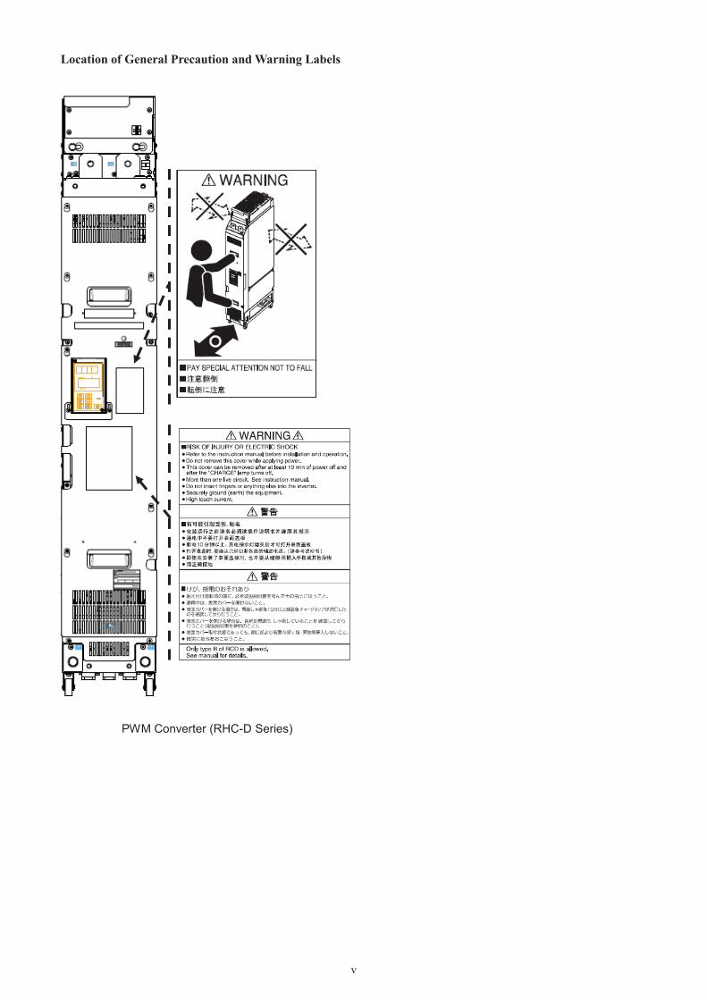
Location of General Precaution and Warning Labels
PWM Converter (RHC-D Series)

vi
Inside of the Products
PWM Converter (RHC-D Series)
If any of warning labels is torn, place an order for a new label with Fuji Electric and replace the torn label.
GENERAL PRECAUTIONSSome drawings in this manual may be illustrated without covers or safety shields for explanation of detail parts. Restore the covers and shields in the original state before using the products.

1-1
1 OutlineOutline of ProductThe high power factor PWM converter with power regenerative function, the RHC-D series is used in combination with a Fuji inverter to return the regenerative energy generated on the load side to the power source, improving the regenerating performance and saving energy.
The converter shapes an input current waveform into a sinusoidal waveform to enable driving at a power factorof 1 so that it is possible to reduce the capacity of the power supply equipment.
As well, the converter is useful for the replacement of conventional applications using braking resistors, such as cranes and vertical transfer machines and it is compliant with the "Guideline for Suppressing Harmonics by Customers Receiving High Voltage or Special High Voltage" (conversion coefficient Ki = 0).
With simplified operation, it is possible to monitor the input power supply, current, power, and load factor,configure function codes, and check alarm history.
Various communications options provided allow you to monitor data from a remote site easily or to integrate the converter in the customer's system without difficulty.
The converter also applies to large capacity, low-voltage inverters by controlling sharing of load to the inverter uniformly with the parallel connection option and input transformer.
Guideline for Suppressing HarmonicsThe PWM control regulates the power supply current into a sinusoidal wave to contribute to substantial reduction of harmonic currents.
Accordingly, the combination with an inverter canhandle the conversion coefficient Ki (specified in the "Guideline for Suppressing Harmonics by Customers Receiving High Voltage or Special High Voltage" issued by the Ministry of Economy, Trade and Industry) as "0" (that is, no generation of harmonics).
Possible to Reduce the Capacity of Power SupplyBy controlling the power factor, the converter suppliesthe in-phase current relative to the power phase voltage, enabling running at a power factor of 1. This makes itpossible to reduce the capacity of the power transformer or the size of the devices to less than those of the standard inverters.
Substantial Increase of Braking PerformanceThe regenerative energy obtained in frequent acceleration/deceleration operation or elevator returns to the power supply side, promoting energy savings.
Since the waveform of the regenerative current is sinusoidal wave, too, there is no need to be anxious about trouble in the power supply system.
MD (CT) mode LD (VT) mode
Continuous regeneration 100% 100%
Short time rating 1 min. 150% 1 min. 110%
Variety of Assured Functions• Monitors the source voltage, current, power, power
supply frequency and other trends.
• Provides three choices of languages (Japanese, English and Chinese) to be displayed on the panel.
• Saves the converter load factor calculated, cumulative run time, and data at the occurrence of alarm into the memory.
• Issues overload and converter overheat early warning signals before the converter stops due to an alarm.
• Shuts down the gate output at the time of amomentary power failure and continues operation immediately after the power is restored.
• Supports various communications protocols (Fuji links such as T-Link and SX bus, and Open links such as CC-Link and RS-485)

2-1
2 Before Use
• Inadequate handling of the product during lifting or transportation will cause injuries or breakage of the product. Trained personnel must handle the product, using suitable devices.Injury may result.
2.1 Acceptance InspectionUnpack the package and check if the converter unit, filter stack and peripheral devices are what you ordered and they are free from damage. Also check that the models of the filter stack and peripheral devices match the converter type,referring to Section 3.3.8 "Peripheral devices."If you suspect the product is broken or not working properly or if you have any questions about your product, contact your dealer or nearest Fuji sales representative and give him/her information about the following items.
(1) PWM converter
Check that the converter is the type you ordered. You can check the type and specifications on the rating plate shown in Figure 2.1-1. The keypad comes with the converter unit.
TYPE: Type of PWM converterRHC 220 S – 4 D E
SOURCE: Power supply ratingOUTPUT: Output ratingWEIGHT: MassSER. No.: Product number Manufacturing date
2 8 A 4 5 6 A 0 0 0 2 A A <2 3 2>Production weekThis indicates the week number that is numbered from 1st week of January.The 1st week of January is indicated as '01'.Production year: Last digit of year
Figure 2.1-1 Rating Plate
Shipping destination/Instruction manual languageJ: Japan/Japanese, E: EU/English, C: China/ChineseSeries name D seriesPower supply voltage 4: 400V classStack type S: Standard stack, B: Phase-specific stackStandard applied inverter capacity 220: 220 kWProduct model RHC
- Models of the converter, filter stack, and peripheral devices- Serial number (See below.)- Date of purchase- Inquiries (for example, point and extent of breakage, uncertainties, failure phenomena,
and other circumstances)

2-2
(2) Peripheral devicesWhen no filter stack is used, a boosting reactor, harmonics suppression filter (reactor, capacitor and resistor), magnetic contactor, AC fuse, charging resistor and other accessories are separately required. Select those models suitable for the PWM converter. For details, refer to Section 3.3.8 "Peripheral devices."
An AC fuse is separately required even when the filter stack is used.
Note: The peripheral devices do not come with the converter unit. Place a separate order for them.
a) Boosting reactor
b) Filtering reactor
c) Filtering capacitor
d) Filtering resistor
e) Magnetic contactor
f) AC fuse
g) Charging resistor
Note: The shape of each peripheral device varies according to the capacity of the converter.
(3) Optional devices
The following items are options given in Section 3.3.9 "Connecting optional devices."- Zero-phase reactor for reducing radio noise (ACL- B)- Power filter
The following items are options given in Chapter 10.- Control options (OPC-VG7-TL, OPC-VG7-CCL, OPC-VG7-SX, OPC-VG7-SI, OPC-VG7-SIR, OPC-VG7-DIO,
and OPC-VG7-AIO)

2-3
2.2 Appearance of the ProductPWM converter
Figure 2.2-1 Appearance of Converter (RHC132S to 200S-4DE (Rank 3))
Figure 2.2-2 Appearance of Converter (RHC220S to 315S-4DE (Rank 4))
Sub nameplate
Main circuit terminal block
Casters
Cooling fansHoist hole( 26)
P (+) bar
N (-) bar
Hoist hole( 26)
Hoist holes( 26)
Main nameplate
Keypad
Sub nameplate
Cooling fans
Main circuit terminal block
Keypad
Main nameplate
N (-) barHoist hole( 26)
Handle
Hoist holes( 26)
Hoist hole( 26)
Hoist hole( 26)
Handle
P (+) bar
Handle
Handle
Front coverCasters
Front cover

2-4
In the case of the phase-specific stack, a keypad is provided only on the S-PHASE stack.
Hoist hole ( 26)Main nameplate
Front cover
Handle
Keypad Handle
P (+) bar
N (-) bar
Hoist hole ( 26)
Hoist hole ( 26)
Hoist hole ( 26)
Cooling fans
Sub nameplat Casters
Main circuit terminal block
Figure 2.2-3 Appearance of Converter (RHC630B to 800B-4DE (Rank 4))

2-5
2.3 Handling the Product(1) Removing the front coverLoosen the front cover mounting screws and remove the front cover.
When removing the front cover from the PWM converter, slide the blanking cover beneath the keypad down beforehand as shown in the lower right figures.
In the case of the phase-specific stack, only the S-phase stack has a keypad.
Figure 2.3-1 Removal of Front Cover
(2) Removing the keypad
Loosen the keypad mounting screws, insert your finger into the cutout provided in the front cover and remove the keypad slowly. Rough handling may break the connectors.
Figure 2.3-2 Removal of Keypad
Front cover
Keypad mounting screws
Loosen the screws on the blanking cover beneath the keypad.
Slide the blanking cover down.

2-6
2.4 Transportation
Do not hold the covers or components during transportation.The converter may fall or turn over, causing injuries.
When carrying the product, be sure to hold the handles (provided on the front side) or the rear side of the unit. Holding the covers or components may fall or turn over the product. When carrying the product with casters, in particular, take extra care for avoiding turnover.
To use a hoist or crane for carrying the product, pass the hook or rope through hoist holes.
Figure 2.4-1 CarryingDirection and Location of Handles
2.5 Storage Environment(1) Temporary storageStore the product in an environment that satisfies the requirements listed below.
Table 2.5-1 Storage Environment
Item SpecificationAmbient temperature -10 to + 40°C
Places not subjected to abrupt temperature changes or condensation or freezing
Storage temperature (Note 1)
-25 to + 70°C
Relative humidity
5 to 95%(Note 2)
Atmosphere
The product must not be exposed to dust, direct sunlight, corrosive or flammable gases, oil mist, vapor, water drops or vibration. The atmosphere must contain only a low level of salt.
Note 1: Assuming comparatively short-time storage, e.g., during transportation or the like.Note 2: Even if the humidity is within the specified requirements, avoid such places where the product will be subjected to sudden changes in temperature that will cause condensation to form.
Precautions for temporary storage1) Do not leave the product directly on the floor.2) If the environment does not satisfy the specified
requirements listed above, wrap the product in an airtight vinyl sheet or the like for storage.
3) If the product is to be stored in a high-humidity environment, put a drying agent (such as silica gel) in the airtight package described in item 2).
(2) Long-term storageThe long-term storage method of the product varies largely according to the environment of the storage site. General storage methods are given below.
1) The storage site must satisfy the requirements specified for temporary storage.However, for storage exceeding three months, the ambient temperature range should be within the range from -10 to 30 C. This is to prevent electrolytic capacitors in the product from deterioration.
2) The package must be airtight to protect the product from moisture. Add a drying agent in the package to maintain the relative humidity inside the package within 70%.
3) If the product has been installed to the equipment or panel at construction sites where it may be subjected to humidity, dust or dirt, then temporarily remove the product and store it in a preferable environment.
4) If the product has not been powered on for a long time, the property of the electrolytic capacitors may deteriorate. Power the product on once a year.
Handle
Handle
Rear of the unit
Carrying direction

3-1
3 Installation and Connection3.1 Operating EnvironmentInstall the converter in an environment shown in Table 3.1-1.
Table 3.1-1 Environmental Requirements
Item Specifications
Site location Indoors
Ambient temperature -10 to +40°C
Relative humidity 5 to 95% (No condensation)
Atmosphere The converter must not be exposed to dust, direct sunlight, corrosive gases, flammable gases, oil mist, vapor or water drops.The atmosphere can contain a small amount of salt.The converter must not be subjected to sudden changes in temperature that will causecondensation to form.
Altitude 1000 m max.(Refer to Table 3.1-2 for altitudes exceeding 1000 m.)
Vibration 2 to 9 Hz: 0.3 mm (Max. amplitude)9 to 200 Hz: Less than 1 m/s2 (0.1 G)
Table 3.1-2 Output Current Derating Factor in Relation to Altitude
Altitude Output current derating factor
1000 m or lower 1.00
1000 to 1500 m 0.97
1500 to 2000 m 0.95
2000 to 2500 m 0.91
2500 to 3000 m 0.88

3-2
3.2 Installation and Layout
• Prevent lint, paper fibers, sawdust, dust, metallic chips, or other foreign materials from getting intothe converter and filter stack or from accumulating on the heat sink.Otherwise, a fire could occur.
• Do not install or run a damaged converter or filter stack. There should be no parts missing.Injury may result.
• Install the converter in a panel or at places where people can not touch it easily.Electric shock or injury may result.
1) Install the converter and filter stack vertically to arobust structure with specified bolts so that the "PWM CONVERTER" and "FILTER STACK"characters are visible correctly in front, respectively.Do not install them upside down, horizontally, or at an angle.
2) Do not place devices or components in front of the converter. The converter has the display and operating unit on the front and wiring or maintenance/inspection requires removing the front cover.
3) Ensure that the minimum clearances and air channelsshown in Figure 3.2-1 are maintained al all time for ventilation since the converter and filter stack generate heat during operation.The generated heat goes up, so do not route cables or wiring in the space above the converter and filter stack.
• Do not place flammable objects near the converteror filter stack.Fire may result.
Figure 3.2-1 Mounting Direction and Required Clearances
4) Follow Fig. 3.2-2 about clearances of between stacks of Phase-specific
5) The converter generates heat in running. When mounting the converter in a control panel, therefore, take extra care with ventilation inside the panel to prevent the ambient temperature from exceeding the specified limit. Do not install the converter in a small airtight box with poor ventilation.
6) The generated heat is radiated upwards by fans inside the converter and filter stack. Do not install the converter or filter stack beneath devices sensitive to heat.
• Install the converter and filter stack on a base made of metal or other non-flammable material.Fire may result.
7) When the converter is running, the temperature of the heat sink rises to in the vicinity of 90 C. Themounting surface of the heat sink on the back side of the converter and filter stack should be made of material being proof enough against the temperature rise.
• Prevent lint, paper fibers, sawdust, dust, metallic chips, or other foreign materials from getting into the converter or from accumulating on the heat sink.Otherwise, a fire could occur.
• Keep away from the heat sink, filtering resistor, filtering reactor and boosting reactor because they become very hot.Burns may result.
Table 3.2-1 ClearancesA B C D E
Between stacks
Rank 3 10 10 300 350 20Rank 4
From other devices 20 20 -- 350(100) 50
(Unit: mm)
1) Do not install stacks one above the other.2) In space "C" (above the stack's outlet fans),
only a fuse (authorized by Fuji Electric) can be mounted.To mount general devices in the space, select devices whose maximum operating temperature is 70 C and mount them so that they do not interfere with the outlet fans.
3) In space "D" (beneath the stack's inlet), do not block approximately 60% of the area in 350 mm clearance. To install devices in space "D," ensure 100 mm clearance.
E
Cooling fans
Exhaust direction
AB
C
D
3-3
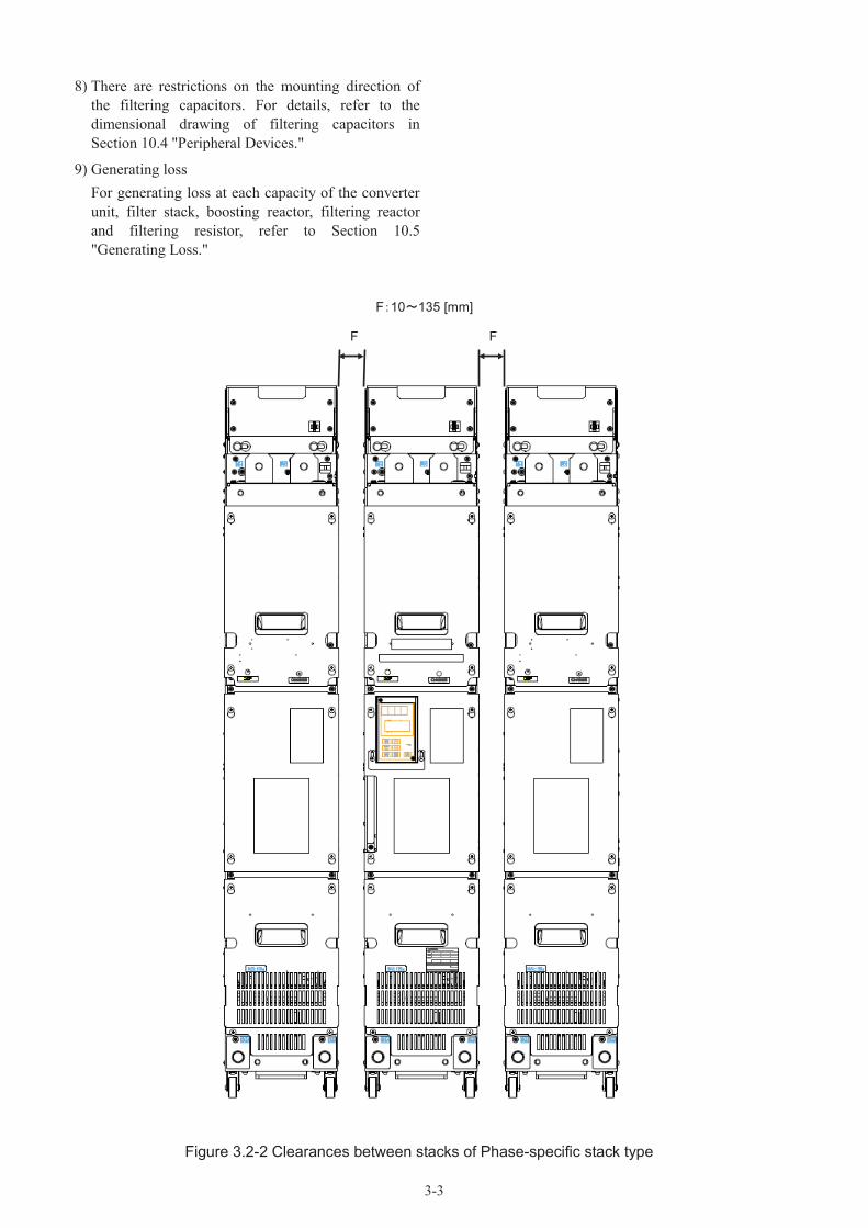
8) There are restrictions on the mounting direction of the filtering capacitors. For details, refer to the dimensional drawing of filtering capacitors in Section 10.4 "Peripheral Devices."
9) Generating lossFor generating loss at each capacity of the converterunit, filter stack, boosting reactor, filtering reactorand filtering resistor, refer to Section 10.5"Generating Loss."
F F
F 10 135 [mm]
Figure 3.2-2 Clearances between stacks of Phase-specific stack type

3-4
Mounting methodRank 3 (132 to 200 kW)1) The fixation plate of the upper part on the back side2) The fixation plate of the lower part on the back side3) The tapped holes for fixing of the upper part on the front side (2×M8-25: In case recommended thickness
of the metal fitting is 2.3mm)4) The tapped holes for fixing of the lower part on the front side (2×M8-25: In case recommended thickness
of the metal fitting is 2.3mm)
Fixing part 2)
Fixing part 1)
UpperMetal fitting
Fixing part 4)
LowerMetal fitting
Fixing part 3)
Figure 3.2-3 The stack mounting method of Rank 3 size (132 to 200 kW)

3-5
Rank4 (220 to 800 kW)1) The fixation plate of the upper part on the back side2) The fixation plate of the lower part on the back side3) The tapped holes for fixing of the upper part on the front side (2×M8-25: In case recommended thickness
of the metal fitting is 2.3mm)4) The tapped holes for fixing of the lower part on the front side (2×M8-25: In case recommended thickness
of the metal fitting is 2.3mm)
Fixing part 1)
Fixing part 2)
Fixing part 3)
UpperMetal fitting
Fixing part 4)
LowerMetal fitting
Figure 3.2-4 The stack mounting method of Rank 4 size (220 to 800 kW)

3-6
3.3 Connection3.3.1 General precautions about connection
• Connect the converter via a circuit protection circuit breaker or earth leakage breaker to the power supply.Fire may result.
• Use the cables of the designated size without fail.Fire may result.
• Connect the grounding cable without fail.Electric shock or fire may result.
• Have wiring work done by a qualified electrician.Electric shock may result.
• Check for power OFF (open circuit) before starting wiring.Electric shock may result.
• Install the main body first before starting wiring.Electric shock or injury may result.
• Do not turn on the product with missing or dropping parts or transportation damage.Electric shock or fire may result.
1) Be sure to connect the power cables to main circuit power terminals L1/R, L2/S, and L3/T of the PWM converter. If the cables are connected to other terminals, the PWM converter will be broken. Check if the source voltage is within the allowable voltage limits specified on the nameplate.
2) Connect the grounding terminal without fail to prevent electric shock, fire or other disasters and to reduce noise.
3) Use crimp terminals, which have high connection reliability, to connect a terminal with a cable.
4) After finishing connections (wiring), check the following items.a. Correct connectionsb. No missing connectionsc. Short circuit between terminals or cables and
grounding fault
5) It takes long time until the smoothingcapacitors of the DC part of the main circuit and filtering capacitors are discharged. To change connections after turning the power off, use a multimeter or the like to check if the DC voltage is reduced to a safe voltage (within +25 VDC) after the charge lamp is unlit. Before shorting a circuit, check that the voltage is reduced to zero; otherwise the remaining voltage (charge) causes a spark.
Figure 3.3-1 Charge Lamp
• Check if the phases and rated voltage of the product agree with the phases and voltage of the AC power supply.Injury may result.
• Check that the DC terminals (P (+), N (-)) of the PWM converter are consistent with the polarity (P (+), N (-)) of the DC terminals of the inverter.Accidents may result.
• Wiring of the PWM converter, filter stack, inverter and motor generates noise. Be careful of malfunction of nearby sensors and devices.Accidents may result.
Charge lampOFF

3-7
3.3.2 Terminal functions
Table 3.3-1 Main Circuit TerminalsConverter stack
Terminal symbol Name Specification
Mai
n ci
rcui
t
L1/R, L2/S, L3/T Main power input Connect to 3-phase power supply via an exclusive reactor or the like. For the phase-specific stack, one terminal connects to one phase (one stack).
P(+), N(-) Converter output Connect to the power input terminals P (+) and N (-) of the inverter.
G Grounding terminal Grounding terminal of the chassis (case) of the converter.R0, T0 Auxiliary control power
inputConnect to the same power system as the main circuit power supply and backup terminal of the control power supply.
R1, S1, T1 Synchronous power supply input for voltage detection
Voltage detection terminal used for the control inside converter; connect to the power supply of the special filter.
R2, T2 Control monitoring input Connection terminal for detection of a blown AC fuse.Connection not required when RHC132S to 315S-4DE is used.
R3, T3 Fan power input Connection terminal for AC cooling fan power inside the stack. Connect to the same power system as the main circuit power supply.Circuits across R1-R3 and T1-T3 are shorted with short wires by factory default. To use the fan power supply individually, remove the short wires and perform wiring individually.Check the configuration of the fan power switchingconnector. To change the configuration, refer to Section 3.3.5 "Details of connection," (6) Fan power switching connector(CN UX).
For the details of basic connection diagram and Phase-specific stack, refer to Section 3.3.4 "Basic connection
diagrams" and Section 3.3.5 "Details of connection".
PWM converter (RHC-D series)
UVW
Inverter
M
3Powersupply
Base drive signal
Auxiliary control power input
Current detection
Voltage detection
+
AVR: Auto voltage regulatorACR: Auto current regulatorPWM: Pulse width modulationfs: Carrier frequencyLr: Boosting reactorFac: AC fuseFdc: DC fuseEdc: DC link bus voltageCdc: Capacitor DC voltagePLC: Programmable logic controller52: Magnetic contactor (MC)73: Magnetic contactor for charging circuitRo: Charging resistor
30A30B30CY5A
Y1Y2Y3
Y5C
Arithmetic control unit
Communications optionPLC
MCCB or RCD/ELCB
FAN
DCF1DCF2
DCF1DCF2
Microswitch for DC fuse blowout
detection
Sequence circuit(Refer to Section 3.3.4 Basic
connection diagrams. )
Filter stack (RHF-D series)
Sequence circuit(Refer to Section 3.3.4 Basic
connection diagrams. )
Microswitch for AC fuse blowout
detection
Alarm output
Relay output (Operation preparation complete)
General-purpose transistor output
General-purpose analog output
Keypad
Display and setting process
Sig
nalo
utpu
tuni
t
Com
mun
icat
ion
proc
essi
ngun
itS
igna
linp
utun
it
RUN/STOPGeneral-purpose terminal
Alarm resetCommon
Figure 3.3-2 Basic Circuit Configuration and Terminals (When no filter stack is used)

3-8
Table 3.3-2 Control TerminalsConverter stack
Item Name Specifications
Inpu
t sig
nals
RUN/STOP command [RUN] Connect across RUN and CM to boost the voltage, or disconnect to stop.
Alarm reset command [RST] After removing the cause of the alarm upon alarm stop, connect across RST and CM to cancel protection and restart operation.
General-purpose transistor input [X1]
Digital input circuit specification
0V
+24V
6.8k
PLC
RUN,X1,RST
CM
PLC signal power supply [PLC] Connect the power supply of the PLC output signals. (Rated voltage 24 (22 to
27) VDC)Digital input common [CM] Common terminal for digital input signals
Out
put s
igna
ls
Alarm output[30A][30B][30C]
Signal is output upon alarm stop after the protective function of the converter is activated.(Contact: 1C. Upon alarm, ON across 30A and 30C)(Contact capacity: 250 VAC 0.3A cos = 0.3)
General-purpose transistor output (Standard: 3 points)
[Y1][Y2][Y3]
Transistor output circuit specification
28-30V
Y1-Y3
CME
Digital output common [CME] Common terminal for transistor output signals. Isolated from terminals CM.
Relay output(Standard: 1 point)
[Y5A][Y5C]
Signal can be selected similarly to Y1 to Y3 terminals.The contact capacity is the same as that of the batch alarm output.
General-purpose analog output [AO1] Outputs monitor signals of analog DC voltage (0 to ±10 VDC).
Analog output common [M] Common terminal for analog output terminals
Charging circuit control output
[73A][73C]
Output for controlling external charging circuitConnect the electromagnetic contactor included in standard accessories.(Contact capacity: 250 VAC 5A max.)
Item min. typ. max.Operating voltage
ON level 0 V - 2 VOFF level 22 V 22 V 27 V
Operating current at ON - 3.2 mA 4.5 mAAllowable leakagecurrent at OFF - - 0.5 mA
Item min. typ. max.Operating voltage
ON level - 1 V 2 VOFF level - 24 V 27 V
Max. load current at ON - - 50 mALeakage current at OFF - - 0.1 mA

3-9
3.3.3 Terminal layout drawing
(1) Main circuit terminals
Figure 3.3-3 (a) RHC132S to 200S-4DE (Rank 3)
Unit: mm

3-10
Figure 3.3-3 (b) RHC220S to 315S-4DE (Rank 4)
Unit: mmSelect terminal screws so that a clearance of at least 10 mm with respect to the frame can be created.
3-11
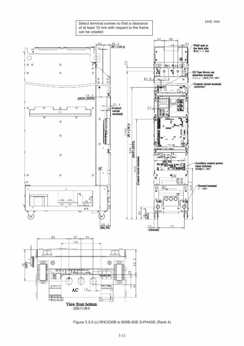
Figure 3.3-3 (c) RHC630B to 800B-4DE S-PHASE (Rank 4)
Unit: mmSelect terminal screws so that a clearance of at least 10 mm with respect to the frame can be created.

3-12
Figure 3.3-3 (d) RHC630B to 800B-4DE R/T-PHASE (Rank 4)
Select terminal screws so that a clearance of at least 10 mm with respect to the frame can be created.
Unit: mm

3-13
(2) Control circuit terminals
Figure 3.3-4 RHC S-4DE
Screw size: M4
Screw size: M3

3-14
3.3.4 Basic connection diagrams
Depending upon the converter capacity and the inverter to be used in combination, the wiring method of the filteringcircuit and sequencer differs. In the table below, select the appropriate basic connection diagram and perform wiring with correct connection sequence and correct polarity. For details of wiring of each section, refer to Section 3.3.5 "Details of Connection."
Basic connection
diagramFiltering circuit PWM converter No. of
converters Inverter
#1Filter stack (*1)RHF160S-4DE
to RHF355S-4DE
MD(CT) mode: RHC132S-4DE to RHC315S-4DELD(VT) mode: RHC132S-4DE to RHC315S-4DE 1 Stack type
#2Configured inperipheral device
MD(CT) mode: RHC630B-4DE to RHC800B-4DELD(VT) mode: RHC630B-4DE to RHC800B-4DE
3*3 stacks
= 1 setStack type
(*1) Contact Fuji Electric if using a peripheral device (73, Fac, Lr, Rf, Lf, Cf) other than a filter stack.

3-15
Basic connection diagram #1
RHC132S-4DE to RHC315S-4DE in MD(CT) modeRHC132S-4DE to RHC315S-4DE in LD(VT) mode
(Note 1) Connect a step-down transformer to lower the voltage of the sequence circuit to voltage shown by figure.(Note 2) Connect the auxiliary power supply input terminals (R0 and T0) of the PWM converter and inverter to the main
power supply via the normally closed contact of the magnetic contactor (52) for the charging circuit without fail. For application to a non-grounded power supply, insert an insulated transformer.
(Note 3) The power of the inverter's AC fan is supplied from terminals R1 and T1, so connect it to the main power supply without passing it through the normally closed contact of 52.
(Note 4) Configure a sequence where preparation for operation of the PWM converter is arranged first before operation signals are issued to the inverter.
(Note 5) Set the timer of 52T at 1 sec.(Note 6) When using microswitches for detection of an AC fuse blowout, assign the X1 terminal of the PWM converter to
an external alarm (THR) and connect microswitches in series.(Note 7) Connect cables to the L1/R, L2/S, L3/T, R1, S1 and T1 terminals in the correct phase order without fail.(Note 8) When supplying 200 VAC for the fan power supply, remove the short wires from terminals R11 and R12 and
from T11 and T12, and then connect it to terminals R12 and T12. These terminals are used only for internal AC fans. Do not use for other uses.
(Note 9) When using filter stack RHF-D series, be sure to configure a sequence which uses 73T. Set the timer of 73T at 1sec.
(Note 10) To use the fan power supply individually, remove the short wires from terminals R1 and R3 and from T1 and T3, and then connect it to terminals R3 and T3.
Symbol Part name of accessoryLr Boosting reactorLf Filtering reactorCf Filtering capacitorRf Filtering resistorR0 Charging resistorFac AC fuseFdc DC fuse73 Magnetic contactor for charging circuit52 Magnetic contactor for power supply

3-16
Basic connection diagram #2
RHC630B-4DE to RHC800B-4DE in MD(CT) modeRHC630B-4DE to RHC800B-4DE in LD(VT) mode
630 800kW Stack type inverter (Phase-specific stack) is consist of three set of Standard stacks of RANK 4 size. In addition to the example of connection of the above-mentioned standard stack, you need connection between eachstacks. The example of connection is shown below
(Note 1) Connect a step-down transformer to reduce the voltage of the sequence circuit to 220 V or below.(Note 2) Connect the auxiliary power supply input terminals (R0 and T0) of the PWM converter and inverter to the main
power supply via the normally closed contact of the magnetic contactor (52) for the power supply circuit without fail. For application to a non-grounded power supply, insert an insulated transformer.
(Note 3) The power of the inverter's AC fan is supplied from terminals R1 and T1, so connect it to the main power supply without passing it through the normally closed contact of 52.
(Note 4) Configure a sequence where preparation for operation of the PWM converter is arranged first before operation signals are issued to the inverter.
(Note 5) Set the timer of 52T at 1 sec.(Note 6) Assign any of the X1 through X9 terminals of the inverter stack to an external alarm (THR).(Note 7) Connect cables to the L1/R, L2/S, L3/T, R2, T2, R1, S1 and T1 terminals in the correct phase order without fail.(Note 8) To use the fan power supply individually, remove the short wires from terminals R1 and R3 and from T1 and
T3, and then connect it to terminals R3 and T3.
Symbol Part name of accessoryLr Boosting reactorLf Filtering reactorCf Filtering capacitorRf Filtering resistorR0 Charging resistorFac AC fuseFdc DC fuse73 Magnetic contactor for charging circuit52 Magnetic contactor for power supply6F Magnetic contactor for filtering circuit

3-17
3.3.5 Details of connection
Connect (1) Main power supply circuit, (2) DC link circuit, (3) Grounding circuit, (4) Control circuit, (5) Auxiliary control power input circuit in this order.
For the cable size, refer to Section 3.3.7 "Cable Size Applicable to Main Circuit."
• Check that the power is turned off (with open circuit) before conducting wiring.Electric shock may result.
• Do not turn on the converter with missing or dropping parts or damage given during transportation.Electric shock or fire may result.
• Check that the phases and rated voltage of the product agree with the phases and voltage of the AC power supply.Injury may result.
• Keep consistency in the polarity between the DC power supply terminals P (+) and N (-) of the converter and the main circuit DC terminals P (+) and N (-) of the inverter.Fire may result.
• The PN wiring length to the DC link bus terminal must not exceed 5 m.Fire may result.
(1) Main circuit power supply input terminals (L1/R, L2/S and L3/T)
RHC132S to 315S-4D (Filter stack)
Connect the L1/R, L2/S and L3/T main circuit power supply terminals to the U0, V0 and W0 terminals of the dedicated filter stack.
RHC630B to 800B-4D (Peripheral devices)
Connect the L1/R, L2/S and L3/T main circuit power supply terminals via AC fuses, boosting reactors, filtering circuits, magnetic contactors (52) for the power supply, MCCB or RCD/ELCB to the power supply as shown in Figure 3.3-5.
L1/R L3/TL2/S
R1
T1
S1
Pow
er
supp
ly
Circuit breake
r
Control terminal
Boosting reactor
Main power supply input terminal
Reactor for harmonic filter
Capacitor for harmonic filter
Resistor for harmonic filter
AC fuse52
Figure 3.3-5 Connection of Main Circuit Power Supply

3-18
a) The wiring distance between the capacitor for harmonic filter and power supply line must not exceed 5 m.
Note: Otherwise the wiring inductance deteriorates the effect of the filter.
L1/R L3/TL2/S
Boostingreactor
Capacitor for harmonic filterL
5m
Main power supply input terminal
Resistor for harmonic filter
Figure 3.3-6 Wiring Length of Filtering Capacitor
b) Connection of filtering resistor
Since a filtering resistor generates heat, install it at a place where other devices are not subject to the heat. Note that the wiring length should be 5 m or less.
• Connect the reactor for harmonic filter and boosting reactor in correct positions.Fire may result.
Note: There is danger of a broken converter.
c) When connecting the reactor for harmonic filter, do not make a mistake in the positions of the reactor for harmonic filter, resistor for harmonic filter, capacitor for harmonic filter and boosting reactor.
L1/R L3/TL2/S
R1 T1S1
52
Boostingreactor
Main power supply input terminal
Reactor for harmonic filter
Pow
er s
uppl
y
Capacitor for harmonic filterControl terminal
Resistor for harmonic filter
Figure 3.3-7 Connection of Reactor

3-19
d) Connect an electromagnetic contactor (MC) for power supply so that the converter or inverter can be disconnected from the power supply upon activation of the protective function to prevent the failure or accident from propagating.
L1/R L3/TL2/S
R1 T1S1
52
T0R0
Controlterminal
Circuitbreaker
Pow
er s
uppl
y
Reactor for harmonic filter
Main power supply input terminal
Control power supply terminal
Figure 3.3-8 Connection of Magnetic Contactor
• Never connect a DC reactor.Fire may result.
Note: Otherwise the voltage of the DC circuit resonates to become unstable, possibly resulting in breakage of equipment.

3-20
(2) Converter output terminals (P(+), N(-))
Connect the converter output terminals (P(+) and N(-)) to the inverter DC input P(+) and N(-). The premise is that this connection uses busbars. When using wires for connection, however, keep the wiring length between stacks within 2 m. When using wires for connection to the PN branch bars or PN branch terminals, keep the wiring length within 2 m and put the wires close together (or twist them together).
Figure 3.3-10 Restrictions on Using Wires for Connection to PN Terminals
(3) Grounding circuit
• Be sure to connect the grounding terminal E (G).Fire may result.
Be sure to connect the grounding terminal E (G) of the PWM converter and that of the filter stack for safety and noise reduction.From the view of noise reduction, a low circuit impedance is necessary to suppress noise generation and reduce mutual effects on pieces of equipment. Therefore connect a thick and short cable from the grounding terminal to the grounding electrode prepared in common with the inverter system.
PN busbar
DCF
Within 2 m
Within 2 m
Converter stack
Inverter stack
PN branch bar(PN branch terminal)
Put close together
DCF
Converter stack
Inverter stack
Within 2 m between stacks
Use identical wires.
Put close together

3-21
(4) Control circuit
In general, the covers of the control signal wires are not specifically designed to withstand a high voltage (i.e., reinforced insulation is not applied). Therefore, if a control signal wire comes into direct contact with a live conductor of the main circuit, the insulation of the cover might break down, which would expose the signal wire to a high voltage of the main circuit. Make sure that the control signal wires will not come into contact with live conductors of the main circuit.
Failure to observe these precautions could cause electric shock or an accident.
• Noise generates from the converter, inverter, motor and cables. Be careful of malfunction of nearby sensors and devices.Accidents may result.
• Take care of the polarity of the external power supply.Failure may result.
Notes:- Do not add voltage to control terminals other than control terminals Y5A, Y5C, 30A, 30B, 30C, 73A and 73C.
Otherwise the converter will be broken.
- The common terminals CM and CME are isolated from each other. Do not connect across these terminals. Otherwise mutual interference of circuits may cause malfunction. As well, do not ground the common terminal.
a) R1, S1 and T1 terminals
The R1, S1 and T1 terminals serve as input terminals of reference signals of the converter. Connect these terminals to the power supply side of a reactor for harmonic filter free from waveform distortion. The wiring length must not exceed 5 m.
L1/R L3/TL2/S
R1 T1S1
52
T0R0
Controlterminal
Circuitbreaker
Pow
er s
uppl
y
Reactor for harmonic filter
Main power supply input terminal
Control power supply terminal
Figure 3.3-11 Connection of Voltage Detection Terminals

3-22
b) Digital input terminals (RUN, X1, RST, PLC and CM)
1) Normally a circuit across the digital input terminal and the CM terminal is connected or disconnected. On the other hand, if the open collector output of a programmable logic controller driven by an external power supply is used to turn on or off, a routing circuit may cause malfunction.If this happens, use a PLC terminal to connect as shown in Figure 3.3-12.
2) When using a contact input, use a contact free from contact faults having high contact reliability.Example: Fuji Electric's control relay HH54PW
Programmablelogic controller Converter
PLC
RUN, X1, RST
CM
24 VDC
Externalpowersupply
Figure 3.3-12 Prevention of Routing Caused by External Power Supply
c) Transistor output terminals (Y1, Y2, Y3 and CME)
1) Take care of the polarity of the external power supply.
2) When connecting a control relay, connect a surge absorbing diode at both ends of the exciting coil.
d) Contact output terminals (Y5A, Y5C, 30A, 30B and 30C)
Contact capacity is 250 VAC 0.3A cos = 0.3. If these specification values are exceeded, connect a relay having a larger contact capacity. If two or more contacts are necessary, connect a relay having multiple contacts to increase contacts.
X
30A
30B
30C
Power supply
Contacts
Contactoutput
30
Figure 3.3-13 Increase in Contact Capacity and Number of Contacts
e) Charging circuit control signals (73A and 73C)
These are control output signals for the charging circuit. Perform wiring, referring to the basic connection diagrams.
f) Charging circuit drive input (73-1 and 73-2)
These are control input signals for the charging circuit. Perform wiring, referring to the basic connection diagrams.

3-23
g) Connection of surge absorber
When an exciting coil of an electromagnetic contactor, relay or the like in the control circuit or periphery circuit of the converter is opened or closed, surge voltage (noise) generates according to a steep change of the current. This surge voltage may cause malfunction of the converter control circuit or peripheral devices. If this happens, connect a surge absorber at both ends of the faulty coil.
X Y Z
AC DC+
- Diode
S2-A-Oor
S1-B-O
S2-A-Oor
S1-B-O
Excitingcoil
Figure 3.3-14 Connection of Surge Absorber

3-24
h) Wiring for control circuit
1) Route the control circuit wiring along the left-hand side of the converter as shown in Figure 3.3-15.
2) Route the auxiliary control power input wiring and auxiliary fan power input wiring along the right-hand side of the converter as shown in Figure 3.3-15.
Note: For wires to be connected to the control circuit terminals, use shielded wires or twisted vinyl wires.
Figure 3.3-15 Routes of Control Circuit Wiring
Control terminals
Control circuit wiring
Auxiliary control power input wiringAuxiliary fan power input wiring

3-25
i)Wiring between stacks of Phase-specific stack type
In case of Phase-specific stack type (RHC630-800B-4DE), you need to wire between each stacks after installation the inverters. Refer to Figure3.3-16 3.3-18.
Figure3.3-16 Wiring between GATE P.C.B, FUSE P.C.B and POWER P.C.B of Phase-specific stack type

3-26
Figure3.3-17 Wiring between AUXILIARY POWER P.C.B ,CT(current detector) cable of Phase-specific stack type.
Figure3.3-18 Detail of A that is wiring route of CT cable of Phase-specific stack type.

3-27
(5) Auxiliary control power supply circuit
• To apply to inverters belonging to group A, C, or E shown in Table 3.3-3, connect the control power auxiliary input (R0 and T0) through the b contact of an electromagnetic contactor (52).Fire may result.
Note: The energy of the boosting reactor may obstruct the control power supply circuit through the source circuit during converter operation, possibly causing an overheated or burned control power supply circuit. Be sure to connect through the b contact of the electromagnetic contactor (52) to the main power supply.
The wiring pattern of the R0 and T0, R1 and T1 terminals to the inverter varies according to the applicable inverter.As listed below, perform wiring according to the applicable inverter groups.
Table 3.3-3 Wiring Method to R0/T0/R1/T1 Terminal
Applicable inverter R0 and T0 terminal wiring method R1 and T1 terminal wiring method
FRN30SVG1S-4to FRN75SVG1S-4
Insert b contact of the contactor (52) in the wiring of R0 and T0.
No R1 or T1 terminal
FRN90SVG1S-4 or above Refer to the basic connection diagrams given in Section 3.3.4.
The converter operates even if the power is not supplied to the control power supply auxiliary input (R0 and T0) terminals. If the power supply electromagnetic contactor of the converter is turned off (with an open circuit) after the protective circuit is activated, the control circuit of the converter is turned off, too, to stop alarm warning outputs (30A, 30B and 30C) and cancel alarm display. To prevent this, supply the same AC voltage as that of the main circuit power supply to the control power supply auxiliary input (R0 and T0) terminals.
• Precautions for application to non-grounded power supply
If the converter is connected to a non-grounded power supply, a grounding fault accident occurring at the inverter output configures a routing circuit via the ground, causing breakage of the inverter.
To connect to the non-grounding power supply without possibility of breakage, connect an insulated transformerbetween the power supply and R0 and T0 for each of the converter and inverter. In this case, there is no need to insert the normally closed contact of 52 relay.
Connection of an insulated transformer is also recommended for an unknown power supply.
Choose the capacity of the transformer according to the capacity requirements of the converter and inverter, based on the table below.
Model Capacity of transformer Applicable converter
RHC 200VA RHC132S-4DE RHC315S-4DERHC630B-4DE RHC800B-4DE
Model Capacity of transformer Applicable inverter
SVG1 200VA FRN30SVG1S-4E FRN315SVG1S-4EFRN630BVG1S-4E FRN800BVG1S-4E
VG1G1
150VA FRN22VG1S-4 or below200VA FRN30VG1S-4 FRN220VG1S-4300VA FRN280VG1S-4 FRN630VG1S-4

3-28
(6) Fan power switching connector (CN UX)
When the main circuit source voltage is within the range shown in Table 3.3-4, set the auxiliary power switching connector "CN UX" on the U2 position. In other cases, leave it on the U1 position (factory default). For detailed switching instructions, see Figure 3.3-20.
Some inverters are equipped with similar auxiliary power switching connector "CN UX." For them, change the connector position in the same way. For detailedswitching procedure, refer to the inverter's instruction manual.
Table 3.3-4 Main Circuit Source Voltage RequiringConfiguration Change of Fan Power Switching Connector
Frequency (Hz) Source voltage range (V)
50 380 to 39860 380 to 430
The switching connectors are located on the power printed circuit board located above the control printed circuit board as shown in the figure at the right.
Note: To remove each of the jumpers, pinch its upper part of the tab between your fingers, unlock it, and pull it up.When mounting the jumper, fit it over the connector until it snaps into place.
<Enlarged view A>
The factory default position of CN UX is U1.
<Detail odd angle view A>
Factory default Jumper removed from After switching(CN UX: U1) the connector (CN UX: U2)
Figure 3.3-20 Power Switching Connector
CN UX
A
R0 T0Auxiliary control power input terminal
Fan power switching connector (CN UX)
U1 U2
F t d f lt Jumper removed from After switching
CN UX (red)

3-29
3.3.6 Precautions for installation(1) The circuit breaker on the power supply side may trip according to some failures of the converter.
In such a case, the auxiliary power supply is also turned off and the failure is not retained. When the circuit breaker is turned on to turn on the contactor, the breakage inside the converter may propagate.To prevent this kind of trouble from propagating, it is recommended to retain the alarm signal of the converter in an electrically reset relay.
The circuit without an electrically reset relay is shown below.
Figure 3.3-21 Precautions for installation
(2) Because a high frequency current flows through the boosting reactor, the reactor itself generates slight electromagnetic noise.
(3) Be sure to connect to a power supply rated at larger than the power supply capacity requirement specified in Section 10.1 "Standard Specifications."(If the power supply capacity is too small, the converter and/or inverter may be broken due to distortion of waveform of the power supply.)Among all, problems may arise if the power supply boosted with a small capacity transformer is used for the main circuit power supply for the sequence check of the control panel. In this case, disconnect the circuit across RUN and CM of the converter and perform the sequence check of other parts without operating the converter.
52 RUN
30A30C
Opera-tion
FX
Operation preparation
S
30X
R30
Reset
30X
RUN
CM
THR
CM
FWD
CM
30A
30B
30C
Y5A
Y5C
30C 30C
30A
30B
30C
PWM converter Inverter
30A 30A
5230
RUNFX
30X
RUN
CM
THR
CM
FWD
CM
30A
30B
30C
Y5A
Y5C
30B
30C
30A
30B
30C
PWM converter Inverter
52 RUN
30B30C
Operation
FX
Operation preparation
RUNFX
52

3-30
3.3.7 Tightening torque and wire size for devices applicable to the main circuit
(1) Tightening torqueConverter stack
Type Tightening torque (N•m)
RHC -4DE Input circuit[L1/R, L2/S, L3/T]
Output circuit[P(+), N(-)]
Groundingterminals
[ G]
[R0, T0][R1, S1, T1]
[R2, T2][R3, T3]
[73A, 73C]
[DCF1, DCF2]
Control terminals
M3 screw M4 screw
132S
48 48 48 1.8 0.5 0.7 1.2
160S
200S
220S
280S
315S
630B
710B
800B
(2) Recommended wire sizeConverter stack (Ambient temperature: 40°C)
RHC -4DE Main power input [L1/R L2/S, L3/T],
Converter output[P(+), N(-)] Grounding
terminals[ G]
(mm2)
Filteringresistorcircuit
(mm2)
Chargingresistorcircuit
(mm2)
[R0, T0][R1, S1, T1]
[R2, T2][R3, T3]
[73A, 73C](mm2)
Control terminals
[DCF1, DCF2]
(mm2)
MD(CT)mode
LD(VT)mode
Bus bar sizes
(mm2)
Wire sizes
(mm2)
Bus bar sizes
(mm2)
Wire sizes
(mm2)
132S -
t5×30(150)
60
t4×40(160)
60 22
- -
2 1.25
160S 132S 100 100 38
200S 160S
150 150
60
- 200S
220S -
t10×30(300)
t8×50(400)
280S - 200 200
315S 280S 250 250
- 315S 325 325 100
630B -
t10×125(1250)
325×2
t8×50(400) -
150
60
3.5710B 630B 325×3
100800B 710B 325×4
- 800B 325×5 200
(Note 1) The wire size in the above table is for the 600 V HIV insulated wires.(Note 2) The size of wire or bus bar of stack by phase is a part for 1 phase (1 stack).
(3) Rated current of Cu bus barsTable 3.3-5” shows the rated currents of bus bars. However, if the ambient temperature of the cabinet is lower
than 40°C and in some other cases, the derating of the current must be considered.[Precaution about the application of the current and capacity table of bus bars]Select a bus bar based on a temperature of 70°C, which means a temperature rise of 30 K from an ambienttemperature of 40°C. If ambient temperature drops below 40°C, the value of temperature rise increases. Consider a correction factor according to “Figure 3.3-22 Temperature correction factor.” In addition, the reduction rate of

3-31
the supplied current depends on the layout of bus bars. When supplying a large current, plan the current by making reference to Figure 3.3-23
Figure 3.3-22 Temperature correction factor Figure 3.3-23 Derating in installation direction (reference)
Table 3.3-5 Rated currents of CU bus bars
(Note) *1 The selection conditions applied to this table are ambient temperature: 40°C and temperature rise: 30K.
*2 The layout of bus bars is a vertical layout.

3-32
3.3.8 Peripheral devices
(1) RHC132S to 315S-4DE Filter stack application table
MD (CT) mode
RHC-D typeRHF-D (*1) Rated current
of MCCBand ELCB(A)
Magneticcontactor (52)
Fuse (Fac) Microswitch
Type Qty Type Qty. Type Qty. Type Qty.
RHC132S-4DE RHF160S-4DE 1 300 SC-N8 1 170M5446 3
170H3027 3
RHC160S-4DE RHF160S-4DE 1 350 SC-N11 1 170M6546 3
RHC200S-4DE RHF220S-4DE 1 500 SC-N12 1 170M6547 3
RHC220S-4DE RHF220S-4DE 1 500 SC-N12 1 170M6547 3
RHC280S-4DE RHF280S-4DE 1 600 SC-N14 1 170M6499 3
RHC315S-4DE RHF355S-4DE 1 700 SC-N14 1 170M6500 3
LD (VT) mode
RHC-D typeRHF-D (*1) Rated current
of MCCBand ELCB(A)
Magneticcontactor (52)
Fuse (Fac) Microswitch
Type Qty. Type Qty. Type Qty. Type Qty.
RHC132S-4DE RHF160S-4DE 1 350 SC-N11 1 170M5446 3
170H3027 3
RHC160S-4DE RHF220S-4DE 1 500 SC-N12 1 170M6546 3
RHC200S-4DE RHF220S-4DE 1 500 SC-N12 1 170M6547 3
RHC280S-4DE RHF355S-4DE 1 700 SC-N14 1 170M6499 3
RHC315S-4DE RHF355S-4DE 1 800 SC-N14 1 170M6500 3
(*1) Contact Fuji Electric if using a peripheral device (73, Fac, Lr, Rf, Lf, Cf) other than a filter stack.
(2) MCCB/ELCB applicable table
Converter stack typeRated current of
MCCB and ELCB(A)MD (CT)specifications
LD (VT)specifications
RHC132S-4DE 300
RHC160S-4DE RHC132S-4DE 350
RHC200S-4DE RHC160S-4DE 500
RHC220S-4DE RHC200S-4DE 500
RHC280S-4DE - 600
RHC315S-4DE RHC280S-4DE 700
- RHC315S-4DE 800
RHC630B-4DE 1400
RHC710B-4DE RHC630B-4DE 1600
RHC800B-4DE RHC710B-4DE 1800
- RHC800B-4DE 2200
The above table lists the rated current of MCCBs and RCD/ELCBs to be used in the power controlpanel with an internal temperature of lower than 50 C. The rated current is factored by a correctioncoefficient of 0.90 (800AF or below) or 0.85 (1000AF or above) as the RCDs'/MCCBs' and ELCBs'original rated current is specified when using them in a surrounding temperature of 40 C or lower.Select an MCCB and/or RCD/ELCB suitable for the actual short-circuit breaking capacity needed foryour power systems.

3-33
(3) RHC630B to 800B-4DE List of peripheral devices
MD (CT) mode
RHC-D typeCharging circuit
contactorPower supply
contactor Charger resistor AC fuse
(73) Qty. (52) Qty. (R0) Qty. (Fac) Qty.RHC630B-4DE SC-N3 1
SC-N12 3 GRZG400 12 parallel 6
SA598473 2RHC710B-4DE
SC-N4 1 HF5G2655 2RHC800B-4DE SC-N14 3
RHC-D typeBoosting reactor Filtering resistor Filtering reactor Filtering capacitor
(Lr) Qty. (Rf) Qty. (Lf) Qty. (Cf) Qty.RHC630B-4DE LR4-630C 1 RF4-630C 1 LFC4-630C 1 CF4-630C 1RHC710B-4DE LR4-710C 1 RF4-710C 1 LFC4-710C 1 CF4-710C 1RHC800B-4DE LR4-800C 1 RF4-800C 1 LFC4-800C 1 CF4-800C 1
RHC-D typeFilter circuit contactor
(6F) Qty.
RHC630B-4DE SC-N7/SF 1
RHC710B-4DESC-N11/SF 1
RHC800B-4DE
LD (VT) mode
RHC-D typeCharging circuit
contactorPower supply
contactor Charger resistor AC fuse
(73) Qty. (52) Qty. (R0) Qty. (Fac) Qty.RHC630B-4DE
SC-N4 1
SC-N12 3
GRZG400 12 parallel 6
HF5G2655 2RHC710B-4DE SC-N14 3
RHC800B-4DE SC-N16 3Contact your Fuji Electric
representative separately.
RHC-D typeBoosting reactor Filtering resistor Filtering reactor Filtering capacitor
(Lr) Qty. (Rf) Qty. (Lf) Qty. (Cf) Qty.RHC630B-4DE LR4-710C 1 RF4-710C 1 LFC4-710C 1 CF4-710C 1RHC710B-4DE LR4-800C 1 RF4-800C 1 LFC4-800C 1 CF4-800C 1RHC800B-4DE LR4-1000C 1 RF4-1000C 1 LFC4-1000C 1 CF4-1000C 1
RHC-D typeFilter circuit contactor
(6F) Qty.RHC630B-4DE
SC-N11/SF 1RHC710B-4DERHC800B-4DE

3-34
3.3.9 Connecting optional devices
If the power supply capacity is small, voltage distortion is not completely suppressed and electromagnetic noise may generate from the power supply transformer or other devices even if filters are installed.
Noise immunity of peripheral devices and wiring method of the main circuit give large effects on noise, so that the following devices may not be enough to suppress noise.Use shielded cables, metallic piping and other measures for the wiring up to the motor.
(1) Noise suppression option
The following pieces of optional equipment are prepared.Choose them when necessary.
Name (Model) Function
Ferrite ring for suppression of radio noise(ACL- B)
Applicable for suppression of radio noise.Be sure to install it as shown in below Figure, id not might cause “DC fuse blown” by mistake.
Power filter Use to suppress noise generating from inverter.
Capacitor for harmonic filterto reduce radio noise
Use to decrease radio noise.The effect of the noise decrease is achieved for the frequency band of 1 MHz or less that is the AM Radio Frequency belt.
For models and dimensioned drawings of the zero phase sequence reactor and the capacitor for harmonic filter, refer to catalog "Fuji's Inverter FRENIC Series Options" (MH596 ) and user’s manual "FRENIC-VG series For the STACK type"(24A7- -0018 ).
P(+)
N(-)
T0
R0
T0
R0
P(+)
N(-)
T0R0
L1/R
L3/T
L2/S
T0R0
Lr52
Lf
Cf
Rf R2
T2
F
R0
73
R1
T1S1
R3T3
Capacitorfor
harmonicfilter
Filter
FAB
Ferritering Power filter
Ferritering
Converter Inverter
M
U
W
V
G
Figure 3.3-24 Connecting Optional Devices

4-1
4 Preparation for Operation4.1 Inspection and PreparationBefore start, check the following.(1) Connection
• Check that the power cables are not connected to converter output terminals P (+) or N (-).
• Check that wiring to R1, S1 and T1 are made.• Check that wiring to 73A and 73C are made in
compliance with the basic connection diagram.• Check that the boosting reactor and filter are
connected in compliance with the basic connection diagram.
• Check that the grounding terminal is securely grounded.
• When the filter stack applies, check that main power inputs L1, L2 and L3 and main power outputs U0, V0 and W0 are not reversely connected.
• When the filter stack applies, contactor control inputs 73-1 and 73-2 for the charging circuit are connected in compliance with the basic connection diagram.
(2) Check that there is no short-circuit or grounding fault across terminals or naked charged parts.
(3) Check that terminals, connectors and screws are not loosened.
(4) Before turning the power ON, check that theswitches are turned OFF so that turning the power ON does not cause the inverter to start or malfunction. Remove the short bar (if any)between RUN and CM of the converter.
(5) After turning the power ON, check that:a) The charge lamp lights up.b) The LCD monitor on the keypad displays data
specified with function code F04 (LED monitor).(By factory default, the input power displays.)(Check if an alarm is displayed.)
c) The fans incorporated in the converter and filter stack rotate.
4.2 Driving Method
• Keep away from the heat sink because it becomes very hot.Burns may result.
There are various driving methods. Choose the most suitable one, referring to the basic connection diagram.
4.3 Test Run
• Be sure to mount the front cover before turning the power ON (closed circuit). Do not remove the cover when the power is ON.
• Do not operate switches with wet hands.Electric shock may result.
After checking that these is no problem in Section 4.1, arrange wiring for actual operation and perform a test run (with short-circuited between RUN and CM of the converter).For the test run procedure of the inverter, refer to the inverter instruction manual.
(1) Turn the power ON and check that the bar graph shows the correct input voltage and power supply frequency.
(2) Check that the RUN LED on the keypad is lit.(3) Select LED Monitor 4 (DC LINK VOLTAGE) and
check that the displayed value is within the following range. The DC link bus voltage should be automatically adjusted within the following range.Voltage range: 640 to 710 V
(4) Perform a test run of the inverter.
After checking for correct operation in the above test run, start regular operation.
Notes• In the event of a fault in the converter, inverter or
motor, immediately stop it. Investigate the cause of the fault, referring to Section 7.3 "Troubleshooting" or the inverter instruction manual.
• If the circuit breaker is turned ON (closed circuit) to supply power, voltage is output across DC output terminals P(+) and N(-) even if no run command is entered to the converter (even without connection across control terminals RUN and CM).
• To touch the electric circuit even after the power is shut down, make sure that the charge lamp is OFF or the voltage on the circuit has dropped to the safe level using a multimeter. This is because even if the power is shut down, the smoothing capacitors remaincharged and require time to be discharged.

5-1
5 Operation Using the Keypad5.1 Appearance
LED monitor- Four-digit, 7-segment LED monitor- Displays various monitor data as well as alarm codes. (By
factory default, the input power (%) is displayed.)
Indicators- The unit of the monitored data on the LED monitor is
indicated with a bar " " shown at the upper part of theLCD below the applicable unit.If there is an upper order page to the screen shown on the LCD, an UP arrow " " appears at the upper right of the LCD monitor; if there is a lower order page, a DOWNarrow " " appears at the lower right of the LCD monitor.
LCD monitor- Max. 13 characters by 5 lines- Displays various data such as the running status, function
code and data. Because an operation guide scrolls in the lower line of the LCD, the user can operate easily while referring to the guide, even if he/she is not familiar withthe operation method of the keypad. (A bar graph is displayed by factory default.)
RUN LED- Lit upon short circuit across RUN and CM at the terminal
block, or upon activation of the RUN bit in the link.- Unlit upon open circuit across RUN and CM, or upon
deactivation of the RUN bit in the link.
Operation keys- Used to switch screens or change data.
Table 5.1-1 lists major functions of the operation keys.
Table 5.1-1 Functions of Operation Keys
Operation keys Used to:
Go to the menu screen or go to the initial screen of the Running or Alarm mode.
Switch the LED monitor or settle the function code data.
Change data, move the cursor up or down (for selection), or scroll the screen.
Move the cursor among digits during data change or jump to the next function code block (when pressed together with the UP/DOWN key).
Cancel data halfway through modification and move the display screen. When there is an alarm, the key functions as an alarm reset key only on the initial screen of the Alarm mode.
Change the F00 setting (Data protection).
RUN

5-2
5.2 Operation and Display Screen5.2.1 Screen immediately after auxiliary control power supply is turned on
If the power is turned ON only with the control power auxiliary input terminals (R0 and T0) without turning the main circuit power supply ON, the 7-segment LED monitor shows "8888" and the LCD monitor shows "READY." This means that the main circuit is notcharged so that the converter waits for the main power to turn ON.
To change function codes, press the PRG key to switchto the Programming menu.
Initial screen Menu screen

5-3
5.2.2 Screen immediately after the main circuit power supply is turned on
(1) Initial Screen
(2) Operation ScreenF05=0 (GUIDANC)
No run command With run command(waiting for voltage boost)
During running During running(during power running) (during regeneration)
"100%" indicates the incoming power.
F05=1 (GRAPH 1)Bar graph screen 1
F05=2 (GRAPH 2) (* Factory default)Bar graph screen 2
(1) For one or two seconds immediately after the main circuit power is turned ON, the initial screen shown at the left is displayed on the LCD monitor.The 7-segment LED monitor changes in the order of "8888 3333 2222 1111" and switches to the operation screen shown at (2) when the converter is ready to run.
(2) The operation screen has two types: the screen where the converter running status and operation guidance are displayed, and the screen where the running status is displayed graphically with bar graphs.To switch between those screens, use function code F05 "LCD Monitor" (keypad indication "LCD MNTR").(The factory default is bar graph screen 2.)
Switching operation (Operation procedure from the operation screen)a. Press the PRG key to go to the program menu screen.b. In the program menu, use and V keys to move the
cursor to "1: DATA SET." Press the FUNC/DATAkey to go to the function code directory selection screen.
c. In the function code directory selection screen, use the and V keys to move the cursor to "F CODE." Press the FUNC/DATA or >> key to go to the function code selection screen.
d. In the function code selection screen, use the and V keys to move the cursor to F05 "LCD MNTR." Press the FUNC/DATA key to go to the function code setting screen.
e. In the function code setting screen, use the and Vkeys to select the desired screen and press the FUNC/DATA key to determine it. After determining, you will return to the function code selection screen.
f. In the function code selection screen, press the PRGkey to go to the operation screen. Or, press the RESET key three times to go to the directory structure screen, to the menu screen and to the operation screen.
PWM CONVERTER
RHC C-TYPE
STOPPRG PRG MENUF/D LED SHIFT
RUNPRG PRG MENUF/D LED SHIFT
DRVPRG PRG MENUF/D LED SHIFT
REGPRG PRG MENUF/D LED SHIFT
Input power
Effective input current
%PWR 100 200 %Iin 100 200
Input voltage fluctuation
Input frequency fluctuation
V418 440 462
Hz57 60 63
Input powerFull scale: 200% of rated capacity of converterEffective input currentFull scale: 200% of rated current of converter
The real time input voltage is displayed with a black barindicator (min., average and max. values).The real time input frequency is displayed with a black barindicator (min., average and max. values).

5-4
5.2.3 Switching LED monitor screens
Press the FUNC/DATA key when the operation screen is displayed, to switch the data displayed on the LED monitor.
Each time the FUNC/DATA key is pressed, the data displayed on the LED monitor changes.
The data displayed on the LED monitor immediately after the power is turned on follows the setting of function code F04 "LED Monitor (Display Selection)."
Table 5.2-1 Monitor Display
F04 LED monitor unit Resolution0 Input power 1 % 1
1 Input power 2 kW 0.1 to 999.9: 0.11000 to : 1
2 Effective input current A
0.01 to 99.99 : 0.01100.0 to 999.9 : 0.11000 to : 1
3 Effective input voltage V 1
4 DC link voltage V 1
5 Power supply frequency Hz 0.1
Forward scroll Reverse scroll
FUNC/DATAFUNC/DATA +
FUNC/DATA +

5-5
5.2.4 Switching LCD screens
The types of LCD screens of the keypad are as follows.
You can operate easily according to the following program menu displayed on the screen.
Program menu Function
DATA SET You can check data or select a function code to be changed.DATA CHECK A data list is displayed.OPR MNTR You can monitor the current operation status of the converter.I/O CHECK The state of the converter and I/O terminals is displayed.MAINTENANC Data concerning startup of the converter or that concerning trouble occurrence or
maintenance and inspection are displayed.LOAD FCTR The load factor is measured.ALM INF The operation data immediately before occurrence of the latest alarm is displayed.ALM CAUSE A history of 10 past alarms and data about multiple alarms currently occurring are
displayed.DATA COPY A set of function codes of the converter can be saved and copied to multiple converters.

5-6
5.2.5 Configuring function code data
(1) Transition of Data Setting Screen
1. DATA SET2. DATA CHECK3. OPR MNTR4. I/O CHECK
F00 DATA PRTCF01 HARM FILTRF02 RESTARTF03 IR SELECT
F/D
RESET
F CODEE CODEH CODEU CODE
F00 DATA PRTC
0:CHG OK0 1
F00 DATA PRTCF01 HARM FILTRF02 RESTARTF03 IR SELECT
F06 LANGUAGEF07 CONTRASTF08 CAREER FRQE01 X1 FUNC
or F/D
RESET
F/D
F CODEE CODEH CODEU CODE
F CODEE CODEH CODEU CODE
Operation screen
Menu screen
Function code selection screenFunction code settingscreenParent directory screen
F/D
PRG
F01 HARM FILTRF02 RESTARTF03 IR SELECTF04 LED MNTR
V418 440 462 Hz57 60 63
Press the PRG key on the operation screen to go to the menu screen.Using the and V keys, move the arrow at the left end in the menuscreen to select "1. DATA SET" and press the FUNC/DATA key todisplay the function code parent directory screen. Using the and Vkeys, select the parent directory of the desired function code and use theFUNC/DATA key or >> key to go to the function code selection screen.On the function code selection screen, use the and V keys to change thedesired function code.
On the function code setting screen, use the and V keys to enter a value,and press the FUNC/DATA key to determine it.

5-7
(2) Data Setting Method
Press and hold the and V key or select the desired digit with the cursor and change it directly to change data.
Select the function code and press the FUNC/DATA key to go to the data setting screen.
On the data setting screen, press and V keys to increase or decrease the least significant digit displayed on the LCD. Press and hold the and V keys to move the active digit to the left to change at a higher speed. Or press the >> key to select the desired digit and change the data directly. After data is changed, the previous data is simultaneously displayed. Use the old data as a reference. After the desired data is displayed, press the FUNC/DATAkey to save the new data. Or press the RESET key to cancel data change and return to the function code selection screen.
H09 485 ANS 0.01s
H09 485 ANS 0.01s
H09 485 ANS 0.01s
H09 485 ANS 0.01s
0.02s
H09 485 ANS 0.01s 0.03s
H09 485 ANS 0.01s 0.50s
H09 485 ANS 0.01s 0.60s
H09 485 ANS 0.01s 0.60s
H09 485 ANS 0.01s
H09 485 ANS 0.01s 0.70s
Press and hold five seconds.
Releas
H09 485 ANS 0.01s
H09 485 ANS 0.01s
H09 485 ANS 0.01s 1.00s
The active digit moves to the left and the digits in the lower order become "0."
Example of data change 1
Example of data change 2

5-8
The new data of the function code is not reflected on converter operation until the FUNC/DATA key is pressed to save it; there is no change in the action while the data is changed with and V keys. The data may not be changed if the data is protected or data change is prohibited during operation. The reason why the data is not changed includes the following.
Display Cause of prohibition of change Resetting method
DATA PRTCTD Data is protected with function code F00. Change function code F00 to "0."
CNV RUNNING A function code that cannot be changed during operation of the converter is being changed.
Stop converter operation.
Example of data change 3
F04 LED MNTR
0:PWR % 0 5
F04 LED MNTR0:PWR %1:PWR kW
0 5
F04 LED MNTR0:PWR %2:INPUT I
0 5
F04 LED MNTR0:PWR %5:FREQ
0 5
F04 LED MNTR0:PWR %4:DC LNKV
0 5
E14 I/O OP/CL OP
CLRUN X1 Y1 2 3 5 30
E14 I/O OP/CL OP CLRUN X1 Y1 2 3 5 30
E14 I/O OP/CL OP CLRUN X1 Y1 2 3 5 30
E14 I/O OP/CL OP CLRUN X1 Y1 2 3 5 30
E14 I/O OP/CL OP CLRUN X1 Y1 2 3 5 30
E15 RHC-OL-WARE16 FAN STOPE17 I-LIM HYSE18 AO1 FUNC
E14 I/O OP/CL OP CLRUN X1 Y1 2 3 5 30
F/D
The blinking cursor moves among active options only.
Press the F/D key to validate data entry.
or V key: movement in one direction only
• Example of data change 4 is for I/O function setting (normally open/closed).The function code cannot be changed during operation.
Example of data change 4

5-9
5.2.6 Checking function code settings
1. DATA SET2. DATA CHECK3. OPT MNTR4. I/O CHECK
F CODEE CODEH CODEU CODE
Operation screen Menu screen
PRG
F00 0: CHG OKF01 0: CONNECTF02*1: ACTIVEF03 0: CT
F00 DATA PRTC
0: CHG OK0 1
Function codeselection screen
Function codesetting screen
V418 440 462
Hz57 60 63
Press the PRG key on the operation screen to go to themenu screen. Using and V keys, move the arrow at theleft end in the menu screen to select "2. DATA CHECK"and press the FUNC/DATA key to display the functioncode and the setting on the LCD.
After the function code and data are displayed on thescreen, press and V keys to select the desired functioncode to be checked. The method for selecting thefunction code is similar to Section 5.2.5 "Function CodeSetting."
Select a function code, change the data and press theFUNC/DATA key to change data as if the operation ismade on the function code setting screen.

5-10
5.2.7 Monitoring the running status
1. DATA SET2. DATA CHECK3. OPR MNTR4. I/O CHECK
PWR = xxx.x kWIin = xxxx.x AVin = xxx Vf = xxx.x Hz
f = xx.xHzfmax = xx.xHzfmin = xx.xHz3 = xx.xHz
V = xxx VVmax = xxx VVmin = xxx V
Running status monitorscreen 2(Power supply frequency fluctuation)
Running status monitorscreen 3(Input voltage fluctuation)
Running screen
Menu screen
Running status monitorscreen 1
V418 440 462
Hz57 60 63
Press the PRG key on the running screen to go to the menu screen.Using and V keys, move the arrow at the left end in the menu screen to select "3. OPR MNTR" and press the FUNC/DATA keyto display the current state of the converter on the LCD.
The running status monitor includes three screens. Use and Vkeys to switch between screens and check the operation state.
Input power (in kW)Effective input current (in A)Effective input voltage (in V)Power supply frequency (in Hz)
Average power supply frequencyMax. power supply frequency(Maximum sampling value is displayed)Min. power supply frequency(Minimum sampling value is displayed.)Standard deviation of power supply frequency x 3 times (3 )(3 of normal distribution of sampled data)
The quality of the power supply can be judged from the valueof 3 . (Maximum value in each hour)
Note: The displayed maximum value may be a little larger than the actual value due to calculation error during power-on.
Average input voltageMax. input voltage (Maximum sampling value is displayed.)Min. input voltage(Minimum sampling value is displayed.)Note: The displayed maximum value may be a little larger than the actual value due to calculation error during power-on.

5-11
5.2.8 Checking I/O signal states
Press the PRG key on the operation screen to switch to the menu screen. Using and V keys at the left end in the menu screen, select "4. I/O CHECK" and press the FUNC/DATA key to display the state of the converter and optional equipment on the LCD.
Some screens are skipped if the optional equipment is not installed. The I/O check screen includes five screens. Use and V keys to switch between screens and check data.
1. DATA SET2. DATA CHECK3. OPR MNTR4. I/O CHECK
DIOA : OPC-VG7-DIOAIO : OPC-VG7-AIOTLINK : OPC-VG7-TLSI : OPC-VG7-SI (SIR)CCL : OPC-VG7-CCLSX : OPC-VG7-SXFIELD : --TRACE : OPC-RHC-TR
Operationscreen
Menu screen
V418 440 462
Hz57 60 63
I/O signal screenI/O signal (terminal)
: Signal OFF, : Signal ONAnalog output signal (A01)
Operation state screenOperation state
: Signal OFF, : Signal ONRUN: Running, INT: Converter shutoff (Inversion oflogic during operation)DRV: During power running, REG: During regenerationNUV: DC link establishment, ALM: Batch failure
Optional equipment installation data screenOptional equipment data
: Signal OFF, : Signal ONInstalled optional equipment is displayed.
* This screen is displayed if optional OPC-VG7-AIO isinstalled.
AIO option I/O data screenAi3 and Ai4 are invalid.AIO output state 1 (Ao4)AIO output state 2 (Ao5)
* This screen is displayed if optional OPC-VG7-DIO isinstalled.
DIOA option I/O data screenDIOA output state
: Signal OFF, : Signal ON

5-12
5.2.9 Displaying maintenance information
1. DATA SET2. DATA CHECK3. OPR MNTR4. I/O CHECK
TIME = xxxxx hEDC = xxx VTMPI = xxx°CTMPF = xxx°C
Imax = xxx.xx APmax = xxxx.x kW
TCAP = xxxxxh(61000h)
TFAN = xxxxxh(25000h)
5. MAINTENANC
Operation screen
Menu screen
Action state monitor screen 1
Action state monitor screen 2
Action state monitor screen 3
57 60 63
418 440 462V
Hz
Press the PRG key on the operation screen to go to themenu screen. Using and V keys, move the arrow at theleft end in the menu screen to select "5. MAINTENANC"and press the FUNC/DATA key to display data to bechecked during startup of the converter or duringmaintenance and inspection, on the LCD.
The maintenance data screen includes six screens.Using and V keys, switch between screens and checkdata.
Cumulative run hours (The cumulative power-up hours aredisplayed.)Detected DC link voltageMax. temperature inside converter (Maximum temperaturein hour)Max. temperature of heat sink (Maximum temperature inhour)
*Cumulative run hours : 1 is 10 run hours(ex: 1000h is 10000 run hours)
Effective max. input current (Maximum value in hour)Max. input power (Maximum value in hour)
Cumulative life of Pt board capacitorPt board capacitor life judgment level (Fixed)Cooling fan run hoursCooling fan life judgment level (Fixed)

5-13
NRK = xxxxxNRR = xxxxx xxNRO = xxxxx xxNRL = xxxxx xx
MAIN = H1xxxxPWR = H2xxxxKP = K xxxx
OP1 = Q1xxxxOP2 = Q1xxxx
Communication statemonitor screen
ROM versioncheck screen 1
ROM versioncheck screen 2
Communication retry cycles: KeypadCommunication retry cycles, latest error code: RS-485Communication retry cycles, latest error code: TL (CCL)/SXCommunication retry cycles, latest error code: SI option
Latest error codeCommunication error code displayed according to communication state in response to inquiry from linkFor the details of error codes, refer to Section 12.4 "Data Format List".
ROM version: Main control CPU (MAIN)ROM version: Power factor control CPU (PWR)ROM version: Keypad"-----" upon error of main control CPU or power factor control CPU
ROM version: 8-bit BUS option CPU (OP1)ROM version: 8-bit BUS option CPU (OP2)"-----" if CPU is not installed.

5-14
5.2.10 Measuring load factor
1. DATA SET2. DATA CHECK3. OPR MNTR4. I/O CHECK
5. MAINTENANC6.LOAD FCTR
T = 3600sImax = 0.00AIave = 0.00APave = 0%
T = 600sImax = 0.00AIave = 0.00APave = 0%
T = 120sImax = 0.00AIave = 0.00APave = 0%
T = 3600sImax = 56.40AIave = 23.50APave = 10%
Use , V or >> to change measuring time.Measuring condition setting
Measurement start
The displayed measuring time indicates the remaining measuring time. When the measuring time is reduced to zero, measurement is finished.
Load factor measuring timeMax. input currentAverage input currentAverage power consumption (Rated converter capacity:100%)
Running screen Menu screen
Load factor measurement screen
V418 440 462 Hz
57 60 63
Press the PRG key on the operation screen to go to themenu screen. Using and V keys, move the arrow atthe left end in the menu screen to select "6. LOADFCTR" and press the FUNC/DATA key to display theload factor measurement screen on the LCD.
On the load factor measurement screen, you can enterthe maximum current, average current and averagebraking power in the specified time.
The cursor is located at the measuring time. Use theand V key to change the digit at which the cursor blinks.Use the >> key to change the digit where the cursor islocated.
Press the FUNC/DATA key to start to measure the loadfactor. The displayed measuring time decreases. Whenthe time is reduced to "0," measurement is finished.Press the FUNC/DATA key during measurement tointerrupt measurement and display the value measuredup to the timing.
After measurement is finished, the measuring timereturns to the initial value, and the measured load ratiovalues are displayed.

5-15
5.2.11 Displaying alarm information
1. DATA SET2. DATA CHECK3. OPR MNTR4. I/O CHECK
5. MAINTENANC6.LOAD FCTR7.ALM INF
TIME = xxxxxhEDC = xxxVTMPI = xxxx°CTMPF = xxxx°C
PWR = xxx.x kWIin = xx.xx AVin = xxx.x Vf = xxx.x Hz
NRK = xxxxxNRR = xxxxxNRO = xxxxxNRL = xxxxx
Operation screen
Menu screen
Screen for checking operation state at alarm
Screen for checking action state at alarm
Screen for checking communication state at alarm
Screen for checking I/O signal at alarm
V418 440 462
Hz57 60 63
Press the PRG key on the operation screen to go to themenu screen. Using and V keys, select "7. ALM INF"and press the FUNC/DATA key to display the operationdata immediately before the latest alarm, on the LCD.
The alarm data screen includes 10 screens. Using and Vkeys, switch between screens to check data.
Use alarm data to display the data having been effectiveimmediately before the alarm.
Input power at alarmEffective input current at alarmEffective input voltage at alarmPower supply frequency at alarm
Cumulative run hours at alarmDetected link voltage at alarmInternal temperature of converter at alarmHeat sink temperature at alarm
Communication retry cycles at alarm: KeypadCommunication retry cycles at alarm: RS-485Communication retry cycles at alarm: TL (CCL)/SXCommunication retry cycles at alarm: SI option
Input signal at alarm (Terminal block/communication): Signal OFF, : Signal ON

5-16
0/1=xxx xxx-1=xxx xxx-2=xxx xxx-3=xxx xxx
5=xxx4=xxx3=xxx2=xxx
-4=xxx xxx-5=xxx xxx-6=xxx xxx-7=xxx xxx
-8=xxx xxx-9=xxx xxx
-10=xxx xxx
Screen for checking operation state at alarm
* This screen is displayed if optional OPC-VG7-DIO is installed.Screen for checking DIOA option output signal at alarm
Alarm history check screen 1
Multiple alarm check screen
Alarm history check screen 2
Alarm history check screen 3
Alarm codeFrequency
Operation state at alarm: Signal OFF, : Signal ON
Output signal at alarm: Signal OFF, : Signal ON
Latest alarm historyAlarm history (-1 to -3)(Updated each time an alarm occurs. If the new alarm is the same as an earlier one, the frequency increasesby one.)
Multiple alarms(Current alarms are displayed according to the number of alarms.)
Alarm history (-4 to -7)(Updated each time an alarm occurs. If the new alarm is the same as an earlier one, the frequency increasesby one.)
Alarm history (-8 to -10)(Updated each time an alarm occurs. If the new alarm is the same as an earlier one, the frequency increases by one.)

5-17
5.2.12 Displaying alarm history and cause
5=xxx4=xxx3=xxx2=xxx
0/1=xxx xxx-1=xxx xxx-2=xxx xxx-3=xxx xxx
-4=xxx xxx-5=xxx xxx-6=xxx xxx-7=xxx xxx
-8=xxx xxx-9=xxx xxx
-10=xxx xxx
xxxxxxxxxxxxxxxxxxxxxxxxxxxxxxxxxxxxxxxxxxxxxxxxxxxx
5. MAINTENANC6.LOAD FCTR7.ALM INF8.ALM CAUSE
0/1=xxx xxx-1=xxx xxx-2=xxx xxx-3=xxx xxx
Latest alarm
Alarm history
If the data size of selected alarms is too large to overflow the screen, use and V keys to scroll data.
Operation screen Menu screen
Alarm cause screen
0/1= OH1 1-1= LV 15-2= OH1 3-3= LV 1
Latest alarmOH1 Continuous one time
Another previous alarmLV Continuous 15 times
Another alarm having occurred before previous one
OH1 Continuous three timesAnother alarm having occurred before two previous ones
LV One time
Display example
V418 440 462 Hz
57 60 63
Press the PRG key on the operation screen to go to themenu screen. Using and V keys, move the arrow atthe left end in the menu screen to select "8. ALMCAUSE" and press the FUNC/DATA key to displaythe alarm history on the LCD.
Using and V keys, select the desired alarm in thedisplayed alarm history, and press the FUNC/DATAkey to display troubleshooting data of the selectedalarm.
Multiple alarms(Current alarms are displayed according to the numberof alarms.)
Latest alarm historyAlarm history (-1 to -3)(Updated each time an alarm occurs. If the new alarmis the same as an earlier one, the frequency increasesby one.)
Alarm history (-4 to -7)(Updated each time an alarm occurs. If the new alarmis the same as an earlier one, the frequency increasesby one.)
Alarm history (-8 to -10)(Updated each time an alarm occurs. If the new alarmis the same as an earlier one, the frequency increasesby one.)
Description of the alarm selected in the [LED] alarmhistory is displayed.The cause of the alarm selected in the [LCD] alarmhistory is displayed.

5-18
5.2.13 Copying data
Follow the procedure below to copy data.
Load the function code data on the keypad.Remove the keypad.Install the keypad to another converter.Save the function code data to the converter.
Using the verification function, you can verify the data recorded in the keypad against that recorded in the converter and pick up changes.
6. LOAD FCTR7. ALM INF8. ALM CAUSE9. DATA COPY
<COPY; KP-CNV>----- 30-4
READ
<COPY; KP-CNV>----- 30-4
READ
20% 13/64
<COPY; KP-CNV>30-4 30-4
READ
<COPY; KP-CNV>30-4 30-4
WRITE
<COPY; KP-CNV>30-4 30-4
WRITE
80% 51/64
<COPY; KP-CNV>30-4 30-4
READCOMPLETE
100% 64/64
Reading only is allowed if EEPROM data is invalid.
<COPY; KP-CNV>30-4 30-4
WRITE
<COPY; KP-CNV>30-4 = 30-4
VERIFY
<COPY; KP-CNV>30-4 = 30-4
VERIFYCOMPLETE
100% 64/64
<COPY; KP-CNV>30-4 30-4
WRITECOMPLETE
100% 64/64
<COPY; KP-CNV>30-4 = 30-4
VERIFY
80% 51/64
V418 440 462 Hz
57 60 63
Press the PRG key on the operation screen to go to the menuscreen. Using and V keys, move the arrow at the left end inthe menu screen to move the cursor to "9. DATA COPY" andpress the FUNC/DATA key to display the loading mode of datacopy on the LCD screen.
To change to loading, saving or verifying, use and V keys onthe loading mode screen.

5-19
Error handling of data copy function
1) Prohibition of change during operation
If data is saved during converter operation or if the converter is started during saving operation, an error occurs and the screen shows as shown on the right.Stop the converter and press RESET, then repeat saving.
2) Memory error
If data is saved though data has not been saved in the data loading mode to the data memory of the keypad (empty data), or if the converter type (capacity, model, voltage class, etc.) specified in the data having been loaded with data loading function is different from the type of the converter to which data is being saved, an error occurs and the screen shows as shown on the right.
3) Verify error
If difference from converter data is found during data verification in the data kept in the memory of the keypad, the function code number is displayed and an error is displayed as shown on the right, while the data check function is temporarily stopped.To continue the data check function and search for other differences, press FUNC/DATA; to terminate the data check function to do another process, press RESET.
4) Data protection
If data is protected using F00, the screen shows as shown on the right. To continue saving, change the F00 setting to enable data change.
<COPY; KP-CNV>30-2 30-2
WRITECNV RUNNING
Saving during operation
<COPY; KP-CNV>55-4 160-4
WRITEMEMORY ERROR
EEPROM checksum errorNo EEPROM data
Press F/D to continue, or RESET then PRG to interrupt.
<COPY; KP-CNV>30-2 30-2
VERIFYERR: F02
3% 2/64
Verify error
<COPY; KP-CNV>30-2 30-2
WRITEDATA PRTCTD
1% 1/64
Data protected with F00
Press RESET then PRG to interrupt.
Press RESET then PRG to interrupt.
Press F/D to continue, or RESET then PRG to interrupt.

6-1
6 Description of Function Codes6.1 Function Code Tables
Table 6.1-1 Function Codes
Func-tion
Function codesData setting range
Min. incre-ment
unit Factory defaultCode Name
Fund
amen
tal f
unct
ions
F00 Data protection 0 or 1
1 -
0F01 Harmonics suppressing filter (Connection selection) 0 or 1 0F02 Restart mode after momentary power failure 0 or 1 0
F03 Switching between MD and LD drive modes (Current rating switching) 0 or 1 0
F04 LED monitor (Item selection) 0 to 5 0F05 LCD monitor (Item selection) 0 to 2 2F06 LCD monitor (Language selection) 0 to 2 0F07 LCD monitor (Contrast adjustment) 0 to 10 5F08 Carrier frequency 5 to 15 5
Exte
nsio
n te
rmin
al fu
nctio
ns
E01 Terminal [X1] function 0 to 4
1 -
4E02 Terminal [Y1] function
0 to 14
0E03 Terminal [Y2] function 2E04 Terminal [Y3] function 3E05 Terminal [Y5] function 1E06 Terminal [Y11] function
Functions for optional OPC-VG7-DIO
0E07 Terminal [Y12] function 0E08 Terminal [Y13] function 0E09 Terminal [Y14] function 0E10 Terminal [Y15] function 0E11 Terminal [Y16] function 0E12 Terminal [Y17] function 0E13 Terminal [Y18] function 0E14 I/O function (Normally open/closed) 0000 to 007F 0000E15 Converter overload early warning level 50 to 105% 1 % 80E16 Cooling fan ON/OFF control 0 or 1 1 - 0E17 Current limiting signal (Hysteresis width) 0 to 30% 1 % 10E18 Terminal [AO1] function
0 to 10 1 -1
E19 Terminal [AO4] function Functions for optional OPC-VG7-AIO
0E20 Terminal [AO5] function 0E21 AO1 gain
-100.00 to 100.00 (times) 0.01 (times)
1.00E22 AO4 gain Functions for optional
OPC-VG7-AIO1.00
E23 AO5 gain 1.00E24 AO1 bias
-100.0 to 100.0% 0.1 %0.0
E25 AO4 bias Functions for optional OPC-VG7-AIO
0.0E26 AO5 bias 0.0E27 AO1-AO5 filter 0.000 to 0.500 s 0.001 s 0.010
Hig
h pe
rfor
man
ce fu
nctio
ns
H01 Station address (RS-485) Function for built-in RS-485 0 to 255 1 - 1
H02 Error processing Common functions for communicationsoptions and RS-485
0 to 3 1 - 3
H03 Timer 0.01 to 20.00 s 0.01 s 2.00H04 Baud rate (RS-485)
Functions for built-in RS-485
0 to 4
1 -
2H05 Data length (RS-485) 0 or 1 0H06 Parity check (RS-485) 0 to 2 0H07 Stop bits (RS-485) 0 or 1 0
H08 Communications link break time (Timeout) (RS-485) 0.0 to 60.0 s 0.1 s 60.0
H09 Response interval (RS-485) 0.00 to 1.00 s 0.01 s 0.05H10 Protocol selection (RS-485) 0 to 3 1 - 0

6-2
Func-tion
Function codesData setting range
Min. incre-ment
unit Factory defaultCode Name
Hig
h pe
rfor
man
ce fu
nctio
ns
H11 TL transmission format Function for OPC-VG7-TL 0 or 1
1 -
0
H12 Parallel system Functions for OPC-VG7-SI,OPC-VG7-SIR
0 or 1 0
H13 Number of slave stations in parallel system 1 to 5 1
H14 Alarm data deletion 0 or 1 0H15 Current limiter valve (Driving 1)
0 to 150%
1 %
150H16 Current limiter valve (Driving 2) 150H17 Current limiter valve (Braking 1)
-150 to 0%-150
H18 Current limiter valve (Braking 2) -150H19 Current limiter early warning (Level) -150 to 150% 100H20 Current limiter early warning (Timer) 0 to 60 s 1 s 0
Use
r app
licat
ion
func
tions
U01 Reserved. Functions for optionalOPC-VG7-SX
-32768 to 32767
1 -
0
U02 SX bus station number monitor -32768 to 32767 0
U03 Reserved. 0000 to FFFF 0000U04 AVR control response -32768 to 32767 0U05 DC voltage command mode -32768 to 32767 0U06 Reserved. -32768 to 32767 0U07 Reserved. -32768 to 32767 0U08 Reserved. -32768 to 32767 0U09 Reserved. -32768 to 32767 0U10 Reserved. -32768 to 32767 0
Note 1: U01 and U06 to U10 are the function codes for particular manufacturers. Do not change the factory defaults.Note 2: On the keypad, U codes are displayed as USER P1 to USER P10.Note 3: The data of shaded function codes ( ) can be changed when the converter is running. To change the data of other
function codes, stop the converter.

6-3
6.2 Details of Function Codes
F codes (Fundamental functions)
F00 Data protection
F00 specifies whether to protect function code data from accidentally getting changed from the keypad. When the data is protected, the "DATA PRTCTD" displays on the LCD monitor.
To change the F00 data, press STOP + or V.
Setting data Data protection0 Allow data change1 Protect data
F01 Harmonics suppressing filter(Connection selection)
The factory default is "0."
The converter is usually connected with the filter, so leave the F01 default as it is.
Setting data Harmonics suppressing filter0 With filter1 Without filter
Note: Be sure to connect the filter circuit to the converter; otherwise, harmonics will be omitted, damaging other devices.
F02 Restart mode after momentary power failure
F02 specifies the action to be taken by the converter in the event of a momentary power failure. When F02 = 0,the converter activates the undervoltage protective function; when F02 = 1, the converter automatically restarts after restoration of source voltage.
If the circuit across terminals [RUN] and [CM] is short-circuited, an undervoltage alarm occurs when the power is shut down. To avoid this, it is recommended to set F02 to "1."
Setting data Restart mode after momentary power failure
0 Disable1 Enable
F03 Switching between MD and LD drive modes (Current rating switching)
F03 switches between the MD (CT) and LD (VT) drive modes. The standard setting is "0" (MD mode). "100%" means the rated current of the converter unit.
Setting data Current rating switching Overload
0 MD (CT) mode 150%, 1 min.1 LD (VT) mode 110%, 1 min.
Note: Selecting the LD (VT) mode increases the rated current of the converter unit. When switching to the LD (VT) mode, change the external reactor and other peripheral devices, too.
F04 LED monitor (Item selection)
F04 specifies the running status item (listed below) to be monitored on the LED monitor. "100%" of input power 1 means the rated capacity of the converter unit.
Setting data Function Unit0 Input power 1 % 16 bits1 Input power 2 kW 16 bits2 Input current (rms) A 16 bits3 Input voltage (rms) V 16 bits4 DC link bus voltage V 10 bits5 Source frequency Hz
F05 LCD monitor (Item selection)
F05 selects the display contents of the LCD monitor in the Running mode. For each monitor screen, refer to Section 5.2.2 "Screen immediately after the main circuit power supply is turned on."
Setting data LCD monitor (Item selection)0 Operation guide screen1 Bar graph of running data 1
(Input power and input current (rms))2 Bar graph of running data 2
(Source voltage fluctuation and source frequency fluctuation)

6-4
F06 LCD monitor (Language selection)
F06 selects the language to display on the LCD monitor.
Setting data Language0 Japanese1 English2 Chinese
F07 LCD monitor (Contrast adjustment)
F59 adjusts the contrast of the LCD monitor. Increasing the setting data increases the contrast and decreasing it decreases the contrast
Setting data 0, 1 , 2, , 8, 9, 10Contrast Low High
F08 Carrier frequency
The carrier frequency is fixed at 5 kHz even if any value is set to F08. When the OPC-VG7-SIR is mounted, it is fixed at 2.5 kHz.
E codes (Extension terminal functions)
E01 Terminal [X1] function
E01 defines the function of digital input terminal X1.
Setting data Function Symbol0 Enable external alarm trip THR1 Cancel current limiters LMT-CCL2 73 answerback 73ANS3 Switch current limiter values I-LIM4 Option DI OPT-DI
Setting procedure• Select the desired function. Take "73 Answerback" for
example.
• To assign the "73 answerback" function to [X1], set E01 to "2" (73ANS).
• Turn the terminal [X1] (73ANS) ON from an external device to supply a 73 answerback signal.
• Check if the ON/OFF status of [X1] is acknowledged, on the I/O check screen of the keypad.
Turning [X1] ON changes X1 to X1 in the figure shown at the right.
• When the terminal is accessed viathe communications link, use the same screen for checking.
< Configuring contacts as a "normally open" or "normally closed" contact" >Contacts can be configured as a "normally open" or "normally closed" contact, with Function code E14 (I/O function (Normally open/closed)). For details, refer to the description of E14.
Function code data = 0Enable external alarm trip -- THRUpon receipt of THR, the converter trips with alarm
. This signal is internally held, so an input of RSTresets the tripped state. Use this signal to stop the converter because of a failure of an external device.The factory default is a "normally open" contact. To use it as a "normally closed" contact, use Function code E14 to change the setting.
Function code data = 1Cancel current limiters -- LMT-CCLThis digital input signal cancels the current limiters defined by H15 through H18. Upon receipt of LMT-CCL, the converter disables all those current limiters.
RUN Y1 Y5ARST Y2X1 Y3
AO1 = xx.xV

6-5
Function code data = 273 answerback -- 73ANSSince the charging circuit is configured outside the converter, use this function to add an auxiliary contactof the charging circuit magnetic contactor (73) to theready-to-run conditions of the converter.When E01 = 2, if the converter receives no 73ANSwithin 500 ms after the charging circuit control output (73A, 73C) is activated, then the converter trips with alarm .Since this condition is judged only when the main circuit power of the converter is turned ON; the converter does not trip if the 73ANS is turned OFFwhen the main circuit power is ON.
500 ms 500 ms
t
DC
link
bus
vol
tage
Power-on (52)Charging circuit
control output (73A)73 answerback (73ANS)
alarm
Note: When E01 2, no alarm occurs.
Function code data = 3Switch current limiter values -- I-LIMThis digital input signal switches the current limiter values defined by H15 to H18.
Function code dataCurrent limiter values to apply
3
OFF H15 (Drive 1), H17 (Brake 1)
ON H16 (Drive 2),H18 (Brake 2)
Function code data = 4Option DI -- OPT-DIUse this function for special purposes. This function is selected by factory default; however, there is no effect on the control action.
E02 to E13 Y terminals functions
E02 through E13 assign part of control and monitor signals to output terminals [Y1] through [Y3], [Y5], and [Y11] through [Y18].
Setting data Function Symbol
0 Converter running RUN1 Converter ready to run RDY2 Source current limiting IL3 Lifetime alarm LIFE4 Heat sink overheat early warning PRE-OH5 Overload early warning PRE-OL6 Power running DRV7 Regenerating REG8 Current limiter early warning CUR9 Restarting after momentary
power failureU-RES
10 In synchronization with source frequency
SY-HZ
11 Alarm content AL112 Alarm content AL213 Alarm content AL414 Option DO OPT-DO
Setting procedure• Select the desired function. Take "Converter ready to
run" for example.• Assign "Converter ready to run" function to one of
the available contacts (Y1 to Y3, Y5A, and Y11 to Y18). To assign it to Y3, for example, set E04 to "1" (RDY).
• Turn the power ON. When the converter is ready to run, the terminal [Y3] comes ON.
• Check if the ON/OFF status of [Y3] is acknowledged, on the I/O check screen of the keypad.Changing [Y3] from "normally open" to "normally closed" changes Y3 to Y3 in the figure shown at the right.
< Configuring contacts as a "normally open" or "normally closed" contact" >Contacts can be configured as a "normally open" or "normally closed" contact, with Function code E14 (I/O function (Normally open/closed)). For details, refer to the description of E14.
RUN Y1 Y5ARST Y2X1 Y3
AO1 = xx.xV

6-6
Function code data = 0Converter running -- RUNThis output signal comes ON when the converter outputs a voltage (during boosting of DC link bus voltage).
Note: If the DC link bus voltage drops due to amomentary power failure, the converter comes to a stop, turning the RUN off.
Function code data = 1Converter ready to run -- RDYThis output signal comes ON when the converter becomes ready to run after the main circuit power is supplied and a RUN command is entered.
This signal is used as an interlock signal for a run command of the inverter connected with the converter, as shown in the basic connection diagram.
Function code data = 2Source current limiting -- ILThis output signal comes ON when the current command value is limited by current limiter values (H15 to H18).
The hysteresis width for prevention of chattering of signal output is set with E17 "Current limiting signal."
Function code data = 3Lifetime alarm -- LIFEThis output signal comes ON when the cumulative run time of any of the DC link bus capacitor (smoothing capacitor), electrolytic capacitors on the control printed circuit board, and cooling fan inside the converter has approached the end of the service life.
The life judgment depends on the following. The cumulative run time information can be monitored on the maintenance info screen in real time.
Part Life judgment levelDC link bus capacitor Cumulative 87,600 hours
(Cumulative power-on hours of main circuit)
Electrolytic capacitors on control printed circuit board
Cumulative 87,600 hours(Cumulative control power-onhours of converter)
Cooling fans 87,600 hoursThis is the estimated life of the cooling fan at ambient temperature of 30°C.
This function should be used merely as a guide. Daily inspection and periodic inspection are necessary to avoid failures and to continue reliable operation over a long time.
Function code data = 4Heat sink overheat early warning -- PRE-OHThis signal comes ON when the temperature of the heat sink reaches a temperature 5°C lower than the "heat sink overheat alarm ( )" level (X°C).
The heat sink overheat alarm level (X°C) varies according to the combination of the converter capacity and the current rating level (MD (CT) or LD (VT)mode), and it is fixed within the range of approximately70°C to 110°C.
X-15 X-5 X
10 5
Hysteresis: 10�Heat sink overheat
early warning
Active
Inactive Temperature of heat sink
Heat sink overheat alarm level: X�
Function code data = 5Overload early warning -- PRE-OLThis output signal comes ON when the converter overload reaches the converter overload early warning level specified by E15. For details, refer to the description of E15.
Function code data = 6Power running -- DRVFunction code data = 7Regenerating -- REGThe DRV or REG output signal is turned ON during power running or regeneration of the converter,respectively. During no-load running (with current command within 3%), the converter is in the RUN state and both the DRV and REG are turned OFF.
The state can be monitored on the running screen (GUIDANC) of the keypad.
DRV
RUN
REG
- -3% -1% 1% 3% +
: Hysteresis width zone
Current reference value of converter
0

6-7
Function code data = 8Current limiter early warning -- CURThis output signal comes ON when the currentcommand value exceeds the current limiter early warning level specified by H19 and it is kept for the timer period specified by H20.
This signal enables the converter to reduce the load before the current limiter function is activated.
Early warning timer (H20)
Early warning timer (H20)
CUR
Early warning level (H19)
Current limiter activation level
Current command value
t
Function code data = 9Restarting after momentary power failure -- U-RESThis output signal comes ON when the converter detects a momentary power failure and shuts off its output. After the power is restored and the DC link bus voltage exceeds the undervoltage recovery level, this signal goes OFF.
If such a long-time power failure that the control power of the converter is lost occurs when the U-RES is ON, then restoring the power causes the converter to start in the regular startup sequence with the U-RES being OFF.
Function code data = 10In synchronization with source frequency -- SY-HZThis output signal comes ON when the control frequency inside the converter is synchronized with the source frequency. It goes OFF upon detection of out-of-synchronization, momentary power failure, or frequency alarm.
This signal may go OFF when there is distortion or dipping in the source voltage waveform due to adverse power supply conditions.
I
Function code data = 11, 12, 13Alarm content -- AL1, AL2, AL4The combination of these output signals shows the activation state of the converter protective functions.
Alarm content(Converter protective function)
Output terminals[AL1] [AL2] [AL4]
No alarm OFF OFF OFFCurrent error(AOC, ACE) ON OFF OFF
Voltage error(AOU, dOU, ALU, dLU) OFF ON OFF
Main circuit error(ACF, PbF, Er8) ON ON OFF
Input error or external fault(LPU, FrE, OH2) OFF OFF ON
CPU, operation or communications error(Er1, Er2, Er3, Er4, Er6, Erb)
ON OFF ON
Overheat or overload(OH1, OH3, OLU) OFF ON ON
Others (Ar1 to Ar8) ON ON ON
Function code data = 14Option DO -- OPT-DOProvided for particular manufacturers.
E14 I/O function (Normally open/closed)
E14 configures contacts RUN, X1, Y1 to Y3, Y5 and 30RY individually as a "normally open" or "normally closed" contact by software.
OP: OpenCL: Closed
Setting data State0 Normally open1 Normally closed
E15 Converter overload early warning level
E15 specifies the overload early warning signal level to apply before the overload protective function is activated.
To issue an overload early warning, set E15 to less than 100%. When E15 = 100%, the early warning will be issued at the same timing as the overload alarm.
Setting range: 50 to 105%
The overload early warning will be issued when PRE-OL is assigned to any of control terminals [Y1] through [Y3], [Y5], and [Y11] through [Y18] using any of E02 to E13.
E14 I/O OP/CL OP
CLRUN X1 Y1 2 3 5 30

6-8
E16 Cooling fan ON/OFF control
E16 specifies whether to detect the temperature of the heat sink inside the converter and control the cooling fan ON/OFF automatically.
The standard specification is "0" (Disable).
Setting data Cooling fan ON/OFF control0 Disable (Always in operation)1 Enable (ON/OFF control)
Note: The cooling fan works when the converter is running irrespective of the E16 setting.
E17 Current limiting signal (Hysteresis width)
E17 specifies the hysteresis width of the source current limiting signal IL.
Setting range: 0 to 30%
ON
OFF
Current command value
Hysteresis width(E17)
Current limiter value
H15, H16
IL
E18 to E20 AO terminals functions
E18 through E20 assign signals to analog outputterminals [AO1], [AO4] and [AO5] and select AO adjustment signals.
Settingdata Function Symbol Scale
0 Input power PWR ±200%/±10V1 Input current (rms) I-AC +200%/+10V2 Input voltage (rms) V-AC 500 V/10 V3 DC link bus voltage V-DC 1000 V/ 10V4 Source frequency FREQ 100 Hz/10 V5 +10V output test P10 --6 -10V output test N10 --
* Do not set "7" or larger value to E18 to E20 since they are for adjustment by Fuji.
* [AO4] and [AO5] are available only when the OPC-VG7-AIO is mounted.
Setting procedure• Check the devices such as a meter to be connected to
AO terminals together with wiring. Setting "5" enables a +10V output test.
• Select the desired function. Take "DC link bus voltage" for example.
• Assign "DC link bus voltage" function to one of the available AO terminals ([AO1], [AO4] and [AO5]). To assign it to [AO1], for example, set E18 (Terminal [AO1] function) to "3" (V-DC).
• The voltage issued onto the terminal [AO1] can be checked on the I/O check screen of the keypad.
• The gain, bias, and filter can be specified with E21 to E23, E24 to E26, and E27, respectively, for analog outputs.

6-9
Function ApplicationBias Setting bias. For details, refer to the description of E24 to E26.Gain Use gain to view a small output range of data in an enlarged scale or to view a wide output range of data
in a reduced scale. Enter a negative value to inverse the polarity. For details, refer to the description of E21 to E23.
Filter There is no need to change from the factory default 0.010 s (10 ms). If wiring between the AO terminal and the device (e.g., meter) or the device itself is susceptible to noise, this filter function has no effect. Take measures against noise outside the terminal. For details, refer to the description of E27.
Output resolutionThe AO output is the result of D/A conversion of a 12-bit digitaloutput. Because 11 bits (2047) on a single side are issued to the half scale (+12V), the output resolution is 5.86 mV. Accordinglythe binary number for 10 V becomes 1705 (2047 x 10/12).
Voltage output
+12 V
1 bit
5.86 mV (12 V/2047)
+2047 (11 bits)
-12V
4095 (12 bits)
Internal data0
Output cycleSignals are output in sampling cycle of approximately 500 s.
M
P(+)
N(-)
U
W
V
P(+)
N(-)
L1/R
L3/T
L2/S
Lr52
Lf
Cf
Rf
E(G)E(G)
F
R0
73
0: Input power PWR2: Input voltage (rms) V-AC4: Source frequency FREQ
1: Input current (rms) I-AC
3: DC link bus voltage V-DC
Converter Inverter
Motor
To control terminal
To control terminal
Filter
5: +10V output test P106: -10V output test N10
+10V and -10V fixed values are output for adjustment of analog output.

6-10
E21 to E23 AO gain setting
E21 to E23 specify the gain for analog outputs AO1, AO4 and AO5, respectively.Setting range: -100.00 to 100. 00 (times)Note: [AO4] and [AO5] are available only when the OPC-VG7-AIO option is mounted.
+10V
2.50
1.00
0.50
+10V
-1.00
-10V
-10V 0
Output voltage
Control internal data
-2.50
E24 to E26 AO bias setting
E24 to E26 specify the bias for analog outputs AO1, AO4 and AO5, respectively.Setting range: -100.0 to 100.0 (%)Note: [AO4] and [AO5] are available only when the OPC-VG7-AIO option is mounted.
+10V
100.0%
0.0%
-40.0%
+10V
-100.0%
-10V
-10V 0
Output voltage
Control internal data
E27 AO1-AO5 filter setting
E27 specifies the output filter time constant for all analog outputs AO1, AO4 and AO5.Setting range: 0.000 to 0.500 (s)Note: [AO4] and [AO5] are available only when the OPC-VG7-AIO option is mounted.
H codes (High performance functions)
H01 Station address (RS-485)
H01 specifies the station address for the RS-485 communications link.Setting range: 0 to 255
H02 Error processing
H02 specifies the error processing to be performed if a communications error occurs in RS-485, T-Link, SX bus or CC-Link.
Setting data Function0 Forcibly stop ( )1 Run for the period specified by H03 and
then trip.
2 Trip if a communications error persists exceeding the period specified by H03.
3 Continue to run.
H03 Timer
H03 specifies an error processing timer for RS-485,T-Link, SX bus or CC-Link.The timer is available when H02 = 1 or 2.Setting range: 0.01 to 20.00 (s)

6-11
H04 Baud rate (RS-485)
H04 specifies the transmission speed for RS-485 communication.
Setting data Transmission speed0 38400 bps1 19200 bps2 9600 bps3 4800 bps4 2400 bps
H05 Data length (RS-485)
H05 specifies the character length for RS-485communication.For the SX protocol or Modbus RTU protocol, the data length is fixed at 8 bits irrespective of the H05 setting.
Setting data Data length0 8 bits1 7 bits
H06 Parity check (RS-485)
H06 specifies the property of the parity bit for RS-485communication.For the SX protocol, the setting is fixed at even parityirrespective of the H06 setting.
Setting data Parity0 None1 Even parity2 Odd parity
H07 Stop bits (RS-485)
H07 specifies the number of stop bits for RS-485 communication.For the SX protocol, the setting is fixed at 1 bit.
Setting data Stop bits0 2 bits1 1 bit
H08 Communications link break time (Timeout) (RS-485)
H08 specifies the time interval from when the converter detects no access due to a wire break until it outputs a trip signal. This applies to a system that always accesses its station within a predetermined interval during communication using the RS-485communications link.
Setting range: 0.1 to 60.0 (s)(When H08 = 0: No detection)
H09 Response interval (RS-485)
H09 specifies the latency time after receipt of a query sent from the host equipment until sending of the response via the RS-485 communications link.This function allows the converter to send a response timely to a PC whose response is slow.Setting range: 0.00 to 1.00 (s)
H10 Protocol selection (RS-485)
H10 specifies the communications protocol for RS-485 communication.
Setting data Protocol0 Fuji's general-purpose inverter protocol1 SX protocol (Loader protocol)2 Modbus RTU protocol3 Trace protocol
For details, refer to Chapter 9 "Using Standard RS-485Interface."
H11 TL transmission format
H11 specifies the transmission format to be used in transmission via the T-Link with the OPC-VG7-TL option.
Setting data TL transmission format0 4W + 4W1 8W + 8W
For details, refer to Chapter 10 "Control Options."
H12 Parallel system
H12 specifies whether to enable the parallel system functions using the OPC-VG7-SI (SIR) option.
Setting data Parallel system0 Disable1 Enable
For details of this function, contact your Fuji Electric representative.
H13 Number of slave stations in parallel system
H13 specifies the number of slave stations (excluding master) available in the parallel system using the OPC-VG7-SI (SIR) option.
Setting range: 1 to 5For details of this function, contact your Fuji Electric representative.

6-12
H14 Alarm data deletion
Setting H14 to "1" deletes all the alarm history and alarm information held in the converter.
After that, the H14 data automatically reverts to "0."
Setting range: 0 or 1
H15 to H18 Current limiter values(Drive 1 or 2, Brake 1 or 2)
The current limiter values can be specified in two ways--one using H15 to H18 and the other via the communications link.
To select those values, use the digital input signals LMT-CCL (Cancel current limiters) and I-LIM (Switch current limiter values). For details, refer to the description of E01 (Terminal [X1] function).
Setting range: (Driving) 0 to 150%(Braking) -150 to 0%
H19, H20 Current limiter early warning(Level, Timer)
If the current command value exceeds the current limiter early warning level specified by H19 and it is kept for the timer period specified by H20, then the converter issues the current limiter early warning (CUR).
For details, refer to the description of the Y terminals functions (E02 to E13).
Setting range: (Level) -150 to 150%(Timer) 0 to 60 (s)
U codes (User application functions)
U01 (Reserved)
Function code reserved for particular manufacturers. Do not change the setting from the factory default.
Changing the setting from the factory default could influence converter running.Accidents or injury may result.
U02 SX bus station number monitor
This function code applies only when the SX bus option card (OPC-VG7-SX) is used.
U02 reads out the SX bus station number allocated to the converter itself by the MICREX-SX, depending upon the system configuration. (Read-only function)
Note: The U02 data is displayed in decimal. When setting the station number with the rotary switches, however, use the hexadecimal value.
U03 (Reserved)
Function code reserved for particular manufacturers. Do not change the setting from the factory default.
Changing the setting from the factory default could influence converter running.Accidents or injury may result.

6-13
U04 AVR control response
U04 adjusts the control response of the automaticvoltage regulator (AVR).
If the output DC voltage or the input current is not stabilized when the converter is running due to the applied system, then use this function code for adjustment.
Setting data AVR operation mode
0Standard high-response mode(In combination with the same capacity inverter)
1Control mode 1(Applying to a generator power supply or for two or more converters combined)
2 Control mode 2(Others)
U04 = 0 (Standard high-response mode):Select this setting when the converter is used in combination with an inverter of the same capacity and it is connected with the commercial power supply.
U04 = 1 (Control mode 1):Select this setting when- the converter applies to a battery or generator power
supply,- the converter is used in combination with an inverter
of the different capacity or in combination with two or more inverters in DC common connection, or
- two or more converters are connected with the same power supply so that the input current is not stabilized.
U04 = 2 (Control mode 2):This setting suppresses the control response. Select this setting when the DC voltage or input current is not stabilized even when U04 = 1.
U05 DC voltage command mode
When the converter runs, the output DC voltage is boosted from the rectified voltage of the source voltage to a constant value.
The factory default is a variable mode based on the source voltage (U05 = 0). Using U05 enables a fixed mode in which the output DC voltage is constant irrespective of the source voltage, just as the previous models.
Setting data Control mode DC voltage command value
0 Variable mode 320 to 355 V (200 V)640 to 710 V (400 V)
1Fixed mode(Equivalent to previousmodels)
340 V (200 V)680 V (400 V)
U06 to U10 (Reserved)
Function codes reserved for particular manufacturers. Do not change these settings from the factory defaults.
Changing the setting from the factory default could influence converter running.Accidents or injury may result.

7-1
7 Troubleshooting7.1 List of Protective Functions
When resetting the alarm stop state, be sure to check that a run signal is OFF beforehand. Resetting it with the RUN and CM being short-circuited may cause a sudden restart.Accidents may result.
If an alarm occurs in the converter, the converter activates the protective function to immediately stop (trip) itselfand displays an alarm code on the LED monitor. Remove the cause that has activated the protective function or replace faulty parts, and then enter a reset command to cancel the protective function and restart converter operation. Even if a reset command is entered without removal of the alarm cause, the protective function cannot be canceled. For the description of alarms, refer to Table 7.1-1.
Table 7.1-1 Alarm Indication and List of Protective Functions
Name of alarm Indication Description
AC fuse blown ACF The AC fuse outside the converter is blown out due to a short or broken internal circuit.
AC overcurrent AOC The momentary AC current has exceeded the overcurrent detection level due to a short circuit or grounding fault in the power supply circuit.
AC undervoltage ALV
The source AC voltage has dropped below the undervoltage detection level during converter operation.Note that no alarm is issued when F02 (Restart Mode After Momentary Power Failure) = 1.AC undervoltage detection level (400 V system: 176 Vrms)
AC input current error ACE
The difference between the current reference value of the converter and the detected input AC power value has exceeded the input current error detection level.Note that no alarm is issued when F02 (Restart Mode After Momentary Power Failure) = 1.
AC overvoltage AOVThe source AC voltage has exceeded the AC overvoltage detection level.AC overvoltage detection level (400 V system: 552 Vrms)
DC overvoltage dOV
The regenerative current of the inverter has increased (until the regenerative energy has exceeded the braking capacity) so that the DC link bus voltage has exceeded the DC overvoltage detection level.DC overvoltage detection level (400 V system: 800 Vdc)
DC undervoltage dLV
The DC link bus voltage has dropped below the undervoltage detection level due to a voltage drop of the power supply during converter operation.Note that no alarm is issued when F02 (Restart Mode After Momentary Power Failure) = 1.DC undervoltage detection level (400 V system: 371 Vdc)
Input phase loss LPV
This function works immediately after the power is turned ON.The converter has stopped due to a phase loss in the three-phase power supply connected to main power inputs L1/R, L2/S and L3/T or an interphase voltage unbalance in the three-phase source voltage.To reset the alarm state, restart the converter.

7-2
Name of alarm Indication Description
Power line frequency synchronization error FrE
The detected source frequency has gone out of the range from 46 to 54 Hz or 56 to 64 Hz (immediately after power-on only) or it has exceeded the "basic frequency (50/60 Hz) ±15%," or the standard deviation of the source frequency multiplied by three (3 ) has exceeded 5 Hz (at the time of a run command input).Note that no alarm is issued when F02 (Restart Mode After Momentary Power Failure) = 1.
Charging circuit error PbF
This function is enabled only when 73ANS (73 answerback) is selected using the X1 function.There has been no X1 input (that is, the output signals of charging circuit has not output or the magnetic contactor for bypassing the charging circuit has not closed) within 0.5 sec after the charging circuit control output 73A signal wasissued. To reset the alarm stop state, change the X1 function selection or restart the converter.
Heat sink overheat OH1 Due to a stop of the cooling fan(s), etc., the temperature around the heat sink that cools down semiconductor elements of the main circuit has risen.
External alarm OH2 The converter has stopped due to the entry of the external signal THR.
Overheat inside converter OH3 The temperature around the control printed circuit board has risen due to poor
ventilation inside the converter.
Converter overload OLU
The AC source current has exceeded the inverse-time characteristic overload level of the converter shown in Figure 7.1-1.For MD (CT) mode: 150% / 60 sFor LD (VT) mode: 110% / 60 s
Memory error Er1 A data writing error or other errors in the memory have occurred.
Keypad communications error Er2 A keypad transmission error has occurred.
CPU error Er3 A CPU error has occurred.
Network device error Er4
When the converter was driven through the communications link such as RS-485, T-Link, SX bus or CC-Link, a transmission error has occurred due to noise.This alarm is caused by a PLC failure, wire break in the communication path, or failure of options.
Operation procedure error Er6 Two or more network option boards (T-Link, SX Bus, or CC-Link) are mounted.
A/D converter error Er8 An error has occurred in the A/D converter circuit.
Optical network error Erb A transmission error has occurred in the communications link between converters using high-speed serial cards (SI or SIR option).
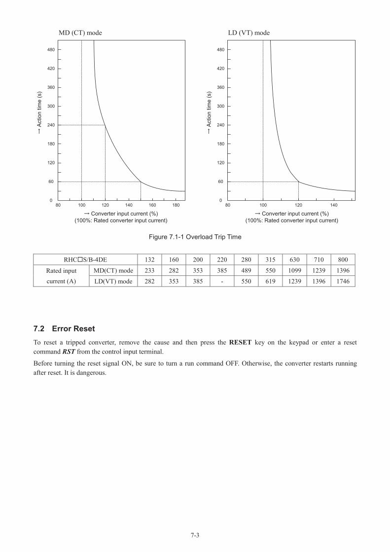
7-3
MD (CT) mode LD (VT) mode
80 100 120 140 160 1800
60
120
180
240
300
360
420
480
Act
ion
time
(s)
Converter input current (%)(100%: Rated converter input current)
80 100 120 1400
60
120
180
240
300
360
420
480
Act
ion
time
(s)
Converter input current (%)(100%: Rated converter input current)
Figure 7.1-1 Overload Trip Time
RHC S/B-4DE 132 160 200 220 280 315 630 710 800
Rated inputcurrent (A)
MD(CT) mode 233 282 353 385 489 550 1099 1239 1396
LD(VT) mode 282 353 385 - 550 619 1239 1396 1746
7.2 Error ResetTo reset a tripped converter, remove the cause and then press the RESET key on the keypad or enter a reset command RST from the control input terminal.
Before turning the reset signal ON, be sure to turn a run command OFF. Otherwise, the converter restarts running after reset. It is dangerous.

7-4
7.3 TroubleshootingWhen the protective function is activated:
(1) Overcurrent (AOC)
Perform wiring correctly. Is the phase order of wiring at L1/R, L2/S, L3/T, R1, S1and T1 correct?
Reduce the load or select a converter having a larger capacity.
Connect the converter to the suitable power supply.
Is the load too large?
Does the source voltage exceed the specification?
OvercurrentAOC
Failure of the converter is probable. Contact FUJI.
NO
NO
NO
NOYES
YES
Remove the short circuit or grounding fault.
Is there a short circuit or grounding fault in wiring or devices in the AC or DC circuit?
YESYES
(2) AC fuse blown (ACF)
[RHC630B~800B-4D]
AC fuse blown ACF
The wiring inside the converter may be short-circuited. Contact FUJI.
Correct the wiring.Are the phase order in the wiring to the AC fuse blowout detection terminals R2 and T2 correct?
NO
NO
Remove devices not specified in the basic connection diagram.
Are devices other than those specified in the basic connection diagram connected between the charging circuit magnetic contactor and converter?
YES
YES

7-5
(3) Overvoltage (AOV, dOV)
Reduce the source voltage to within the upper limit.
Is the source voltage within the specification range?
Is there a power failure during regeneration operation?
Is the regeneration load too large?
Is the function activated at the end of quick acceleration?
Is the function activated when the load is quickly reduced?
Is a generator used for AC power supply?
Set a longer acceleration time to the inverter.
Internal converter adjustment is required.
OvervoltageAOV,dOV
The braking system must be examined. Contact FUJI.Contact FUJI.
NO
NO
NO
NO
NO
YES
YES
YES
YES
YES
YES
NO
Perform wiring correctly. Is the phase order of wiring at L1/R, L2/S, L3/T, R1, S1and T1 correct?
NO
· Set a longer deceleration time to the inverter.
· Examine the regeneration load.
· Examine the converter capacity.

7-6
(4) Undervoltage (ALV, dLV)
Examine the power supply system to satisfy the specifications.
UndervoltageALV,dLV
Is there any defective device or poor connection in the power supply circuit?
Reset and restart operation.
Replace defective devices and correct connection.
The converter may be broken. Contact FUJI.
A converter control circuit failure or malfunction caused by noise is probable. Contact FUJI.
Is the DC (P-N) voltage of the main circuit larger than the detection level specified in Table 7.1-1?
Is this protective function activated when the circuit breaker or magnetic contactor is turned ON?
Is the power supply transformer capacity correct?
Is the source voltage within the specified range?
YES
NO
NO
YES
YES
YES
NO
NO
NO
NO
YES Examine the power supply transformer capacity.
NO
YESYES
Does the charging circuit magnetic contactor (73) go active only when the power is turned on?
Check the sequence circuit of the charging circuit magnetic contactor.
NO
YES
Was there a power failure (incl. momentary one)?
Is there any load requiring a large starting current in the same power supply system?
(5) Overheat inside converter (OH3), heat sink overheat (OH1)
Is the cooling airflow path blocked?
Is the load too large?
Is the ambient temperature within the specified range?
Is the cooling fan rotating?
Improve the environment to keep the ambient temperature within the specified range.
Reduce the load.
Converter failure or malfunction caused by noise is probable. Contact FUJI.
Remove obstacles.
Replace the cooling fan.
YES
YES
YES
YES
NO
NO
NO
NO
Overheat inside converter
OH3
Heat sink overheatOH1

7-7
(6) Converter overload (OLU)
Converter overloadOLU
Is the load too large or has it exceeded the converter overload capability?
Has acceleration/ deceleration repeated frequently?
Converter failure is probable. Contact FUJI.
Examine the operation pattern or select a converter having a larger capacity.
Reduce the load or select a converter having a larger capacity.
NO
YES
NO
YES
(7) Memory error (Er1), CPU error (Er3)
Memory error, CPU errorEr1, Er3
Is the error code removed?
Turn the power OFF temporarily. After the charge lamp (CHARGE) goes OFF, turn the power ON again.
The converter is normal. Continue operation.
Is there any noise source in the vicinity?
Correct faults.
NONO
YES
YES
Converter failure or malfunction caused by noise is probable. Contact FUJI.

7-8
(8) Input phase loss (LPV)
Input phase lossLPV
Are power supply wires connected to all of terminals L1/R, L2/S and L3/T of the main circuit?.
Connect power supply wires to all the three phases.
Are screws on the terminal block loosened?
Is the interphase voltage unbalance large in the three-phase source voltage?
Power supply failure. Examine the power supply system including wiring.
Retighten the screws on the terminal block.
YES
NO
NO
YES
YES
NO
Converter failure or malfunction caused by noise is probable. Contact FUJI.
(9) A/D converter error (Er8)
Converter failure or malfunction caused by noise is probable. Contact FUJI.
A/D converter errorEr8
Is there a short circuit or dust accumulation on the printed circuit board?
Correct faults.YES
NO
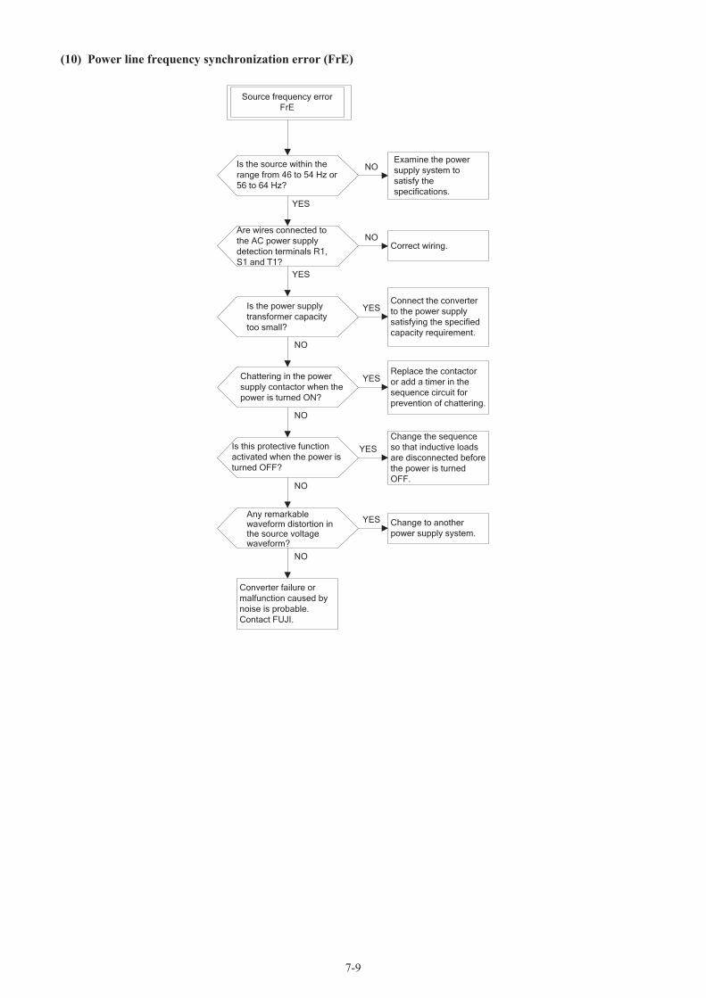
7-9
(10) Power line frequency synchronization error (FrE)
Source frequency errorFrE
Is the source within the range from 46 to 54 Hz or 56 to 64 Hz?
Are wires connected to the AC power supply detection terminals R1, S1 and T1?
Any remarkable waveform distortion in the source voltage waveform?
Chattering in the power supply contactor when the power is turned ON?
Is the power supply transformer capacity too small?
Examine the power supply system to satisfy the specifications.
Change the sequence so that inductive loads are disconnected before the power is turned OFF.
Replace the contactor or add a timer in the sequence circuit for prevention of chattering.
Connect the converter to the power supply satisfying the specified capacity requirement.
Correct wiring.
Change to another power supply system.
Converter failure or malfunction caused by noise is probable. Contact FUJI.
Is this protective function activated when the power is turned OFF?
YES
NO
YES
NO
NO
YES
NO
YES
NO
YES
NO
YES

7-10
(11) Keypad communications error (Er2)
Keypad communication errorEr2
Are the keypad connectors and sockets inserted securely?
Correct faults.
Turn the power OFF temporarily. After the charge lamp goes OFF, turn the power ON again.
Is correct data displayed on the keypad?
Converter failure. Contact FUJI.
The converter is normal. Continue operation.However, if this error occurs frequently, converter failure is probable. Contact FUJI.
YES
NO
NO
YES
(12) External alarm (OH2)
External alarmOH2
Is the alarm signal line of an external device connected to the THR-assigned digital input terminal (X terminal)?
Does the definition of the alarm signal issued by an external device match the definition specified by E14(Normally open/normallyclosed)?
Connect an alarm signal contact.If the terminal is left unconnected, changethe definition of the digital input (X terminal).
Change the "normallyopen/normally closed"definition.
Converter failure or malfunction caused by
noise is probable.Contact FUJI.
YES
NO
YES
NO
Is the alarm function of the connected external device activated?
Remove the cause that activates the alarm function from the external device.(Ex. AC fuse blown )
YES
NO

7-11
(13) Charging circuit error (PbF)
This function is enabled only when 73ANS (73 answerback) is selected using the X1 function.
Charging circuit errorPbF
Is the the output signals of chargingcircuit or auxiliary contact of the magnetic contactor for bypassing the charging circuit connected to the 73ANS-assigned digital input (Xterminal)?
Does the auxiliary contact of the charging circuit magnetic contactor function within 0.5 sec. after the charging circuit control output 73Asignal is issued.*For 280 kW or above capacities:the auxiliary contact of magnetic contactor for power supply should be connected.
Converter failure or malfunction caused by noise is probable.Contact FUJI.
Connect the auxiliary contact to the digital input. Or if the terminal is left unconnected, change the definition of the digital input (Xterminal).
Check the sequence circuit of the charging circuit magnetic contactor.
NO
NO
YES
YES
(14) AC input current error (ACE)
AC input current errorACE
Is there a short circuit or grounding fault in wiring or devices in the AC or C circuit?
Has the load exceeded the current limit level (H15 to H18)?
Was there a momentary power failure?
Correct the short circuit or grounding fault.
Reset and restart operation. Or select the "Restart mode after momentary power failure" (F02 = 1).
Increase the current limit level. Or reduce the load or select a converter having a larger capacity.
Contact FUJI.
NO
NO
NO
YES
YES
YES

7-12
(15) Other errorsThe following alarms are related with options. For details, refer to the description of each option.
Er4: Network device errorThis error could occur when the communications option (RS-485, T-Link, SX Bus, or CC-Link) is used.
Erb: Optical network errorThis error could occur when the high-speed serial card (OPC-VG7-SI or OPC-VG7-SIR) is used.
Er6: Operation procedure errorThis error could occur when option cards are mounted in the wrong way (e.g., mounting options not allowed for use in combination) or a hardware station number of the high-speed serial card (OPC-VG7-SI, SIR) is wrongly set.

7-13
7.4 Converter Cannot Get Ready to RunUpon receipt of a RUN command, the converter outputs the RDY signal ("Converter ready to run") that acts also as an inverter's run condition.
This section provides the troubleshooting procedure to apply when no RDY signal is issued even after the receipt of a RUN command.
No output of RDY signal
Is the charge lamp (CHARGE) lit and does the keypad display something?
Is a RUN command entered?
Are the power supply circuit breaker and magnetic contactor turned ON?
Is the voltage at the power supply terminals (L1/R, L2/S and L3/T)normal?
Is the wiring as specified in the basic connection diagram? Is the phase order correct?
Are synchronous power supply input terminals (R1, S1 and T1) wired?
Alarm trip?
Remove the cause of the alarm, reset the alarm state, and run the converter
Perform correct wiring.
Perform correct wiring to R1, S1 and T1.
Enter a RUN command.
Converter failure is probable. Contact us.
Converter failure is probable. Contact FUJI.
Check for voltage drop,phase loss, poorconnection, poor
continuity and other faults and take corrective
measure.
Turn the power ON.
YES
NO
YES
YES
YES
YES
YES
NO
NO
NO
NO
NO
NO
Are recommended filter stack model, reactormodel and cable size used?
YES
YES
Is the magnetic contactor for the charging resistorand the power supply turned ON with the charging circuit control output 73A signal?
Examine the sequence circuit.
Perform correct wiring and apply adequate peripheral devices.
NO
NO
Does "2222" persist on the LED monitor?
Perform correct wiring to R1, S1 and T1.
NO
YES
YES

8-1
8 Maintenance and InspectionPerform daily and periodic inspections to avoid trouble and keep reliable operation of the converter for a long time. When performing inspections, follow the instructions given in this chapter
• Before proceeding to the maintenance/inspection, turn the power OFF and make sure that the charging lamp (CHARGE) is turned OFF. Further, make sure that the DC voltage across the terminals P(+) and N(-) and the terminal voltage of the filtering capacitor have dropped to the safe level (+25 VDC or below).Otherwise, an electric shock could occur.
• Maintenance, inspection, and parts replacement should be made only by qualified persons.• Take off the watch, rings and other metallic objects before starting work.• Use insulated tools.
Otherwise, an electric shock or injuries could occur.• Never attempt to modify the product.
Electric shock or injury could occur.
Reference: Necessary tools• Phillips screwdrivers Nos. 2 and 3 (for M5 and M6)• Ratchet wrench and sockets (10, 13, 17, and 19 mm)
and extension bar (150 mm desirable)• Nippers and small pliers (required for correction of external wiring)
8.1 Daily Inspection
Visually inspect the converter for operation errors from the outside without removing the covers when the converter is running or the power is ON, as listed below.• Check that the expected performance (satisfying the standard specifications) is obtained.• Check that the surrounding environment satisfies the standard requirements.• Check that the monitors and indicators on the keypad are normal.• Check for abnormal noise, odor or excessive vibration.• Check for traces of overheat, discoloration and other defects.

8-2
8.2 Periodic InspectionBefore performing periodic inspection, be sure to stop the operation, shut down the power, and remove the front cover. According to the items listed in Table 8.2-1, perform periodic inspection including points that cannot be inspected when the power is ON.After turning the power OFF, make sure that the charging lamp (CHARGE) is turned OFF and the DC voltage across the terminals P(+) and N(-)and the filtering capacitor has dropped to the safe level (+25 VDC or below) using a multimeter or the like. This is because even if the power is shut down, the smoothing capacitors remain charged and require time to be discharged.
Table 8.2-1 List of Periodic Inspections
Check point Check item How to inspect Evaluation criteriaEnvironment 1) Check the ambient temperature,
humidity, vibration, and atmosphere (dust, gas, oil mist, or water drops).
2) Check that tools or other foreign materials or dangerous objects are notleft around the equipment.
1) Check visually or measure using apparatus.
2) Visual inspection
1) The standard specifications must be satisfied.
2) No foreign or dangerousobjects are left.
Voltage Check that the AC and DC circuit voltages are correct.
Measure the voltages using a multimeter or the like.
The standard specifications must be satisfied.
Monitor displays
1) Check that the display is clear.2) Check that there is no missing part in
the displayed characters.
1), 2)Visual inspection
1), 2)The display can be read and there is no fault.
Frame, coversand other structural parts
Check for:1) Abnormal noise or excessive vibration2) Loose bolts (at clamp sections).3) Deformation and breakage4) Discoloration caused by overheat5) Contamination and accumulation of
dust or dirt
1) Visual and auditory inspection
2) Retighten.3), 4), 5)
Visual inspection
1), 2), 3), 4), 5)No abnormalities
Mai
n ci
rcui
t
Common 1) Check that bolts and screws are tight and not missing.
2) Check the devices and insulators for deformation, cracks, breakage and discoloration caused by overheat or deterioration.
3) Check for contamination or accumulation of dust or dirt.
1) Retighten
2), 3)Visual inspection
1), 2), 3)No abnormalities
Note: Discoloration of bus bars, if caused, is regarded as normal in the characteristics.
Conductors and wires
1) Check conductors for discoloration and distortion caused by overheat.
2) Check the sheath of the wires for cracks and discoloration.
1), 2)Visual inspection
1), 2)No abnormalities
Terminal blocks
Check that the terminal blocks are not damaged.
Visual inspection No abnormalities
DC link bus capacitor (Smoothing capacitor)
1) Check for electrolyte leakage, discoloration, cracks, and swelling of the casing.
2) Check that the safety valve does not protrude or extend remarkably.
1), 2)Visual inspection
1), 2)No abnormalities
Resistors 1) Check for abnormal odor or cracks in insulators caused by overheat.
2) Check for wire breakage.
1) Olfactory and visual inspection
2) Check the wires visually, or disconnect either wire and measure the conductivity with a multimeter.
1) No abnormalities
2) Within about ±10% of the indicated resistance
Transformer and reactor
Check for abnormal roaring noise and odor.
Auditory, visual, and olfactory inspection
No abnormalities
Magnetic contactor and relay
1) Check for chatters during operation.2) Check that the contact surface is not
rough.
1) Auditory inspection2) Visual inspection
1), 2)No abnormalities

8-3
Inspection point Inspection item Inspection method CriteriaC
ontro
l circ
uit Printed
circuit board and connectors
1) Check for loose screws and connectors.
2) Check for odor and discoloration.3) Check for cracks, breakage,
deformation and remarkable rust.4) Check the capacitors for electrolyte
leaks and deformation.
1) Retighten.
2) Olfactory and visual inspection
3), 4)Visual inspection
1), 2), 3), 4)No abnormalities
Coo
ling
syst
em
Cooling fans 1) Check for abnormal noise and excessive vibration.
2) Check for loose bolts.3) Check for discoloration caused by
overheat.
1) Auditory and visual inspection, or turn manually (be sure to turn the power OFF).
2) Retighten.3) Visual inspection4) Life judgment based on
maintenance info (See Note below.)
1) Smooth rotation
2), 3)No abnormalities
Ventilation path
Check the heat sink, intake and exhaust ports for clogging and foreign materials.
Visual inspection No abnormalities
Remove dust accumulating on the converter with a vacuum cleaner. If the converter is stained, wipe it off with a chemically neutral cloth.
Note: Life judgment based on maintenance infoRefer to the maintenance info shown on the converter keypad for the life judgment of the electrolytic capacitors on the control printed circuit board and that of the cooling fans. Use the info as a guide for the replacement timing.
(1) Life of electrolytic capacitor on the control printed circuit boardThe actual capacitance of the capacitor is not measured but the cumulative power-on time of the control power isdisplayed. The time counter increases in units of hours and ignores the time shorter than an hour.The actual life of the electrolytic capacitor depends largely on the temperature. Use the data merely as a guide.
(2) Life of cooling fanThe cumulative run time of the cooling fan is displayed. The time counter increases in units of hours and ignores the time shorter than an hour.The actual life of the fan depends largely on the temperature. Use the data merely as a guide.
Table 8.2-2 Life Judgment Based on Maintenance Info
Parts Judgment level
Electrolytic capacitor on control printed circuit board 87,600 hours
Cooling fan 87,600 hours *1
*1 Life expectancy of the cooling fan at an ambient converter temperature of 30°C

8-4
8.3 Measurement of Electrical Quantity in Main CircuitBecause the voltage and current of the main circuit power supply (input) and DC output of the converter contain harmonic components, the readings may vary with the type of the meter. Use meters specified in Table 8.3-1 when measuring with meters for commercial frequencies. For measurement at the inverter side, refer to the inverter instruction manual.The power factor cannot be measured by a commercially available power-factor meter that measures the phase difference between the voltage and current. To obtain the power factor, measure the power, voltage and current on each of the input and output sides and use the following formula.
Power factor = x 100(%]
Table 8.3-1 Meters for Measurement of Main Circuit
Item
Input (power supply) side DC link bus voltage(Between P(+) and N(-))
Voltage Current
Name of meter AmmeterAR, S, T
VoltmeterVR, S, T
WattmeterWR, S, T
DC voltmeterV
Type of meter Moving iron type Rectifier ormoving iron type Digital AC power meter Moving coil type
Symbol of meter -
Note: Because the waveform at the input terminals (L1/R, L2/S and L3/T) of the converter is under PWM, measurement with a multimeter or the like causes large measurement errors. To measure the input voltage, measure at the point shown in Figure 8.3-1.
M
E(G)
UVW
N(-)
P(+)
L1/R
L2/S
L3/T
E(G) N(-)
P(+)
VR VT
VS
AT
AR
AS
WR
WT
V+
-
Converter Inverter
F
R0
Figure 8.3-1 Connection of Meters
Electric power(W)
3 x Voltage(V) x Current(A)

8-5
8.4 Insulation Test
Since the converter has undergone an insulation test before shipment, avoid making a Megger test at the customer's site. If a Megger test is unavoidable for the main circuit, observe the following instructions; otherwise, the converter may be damaged.A withstand voltage test may also damage the converter if the test procedure is wrong. When the withstand voltage test is necessary, consult your Fuji Electric representative.Breakage may result.
- +
Megger
E(G)
Terminals of power supply circuit
R1 S1 T1 R0 T0 R2 T2
L1/R L2/S L3/TP
(+)N(-)
R3 T3
Figure 8.4-1 Megger Test
(1) Megger test of main circuita) Use a 500 VDC Megger and shut off the main power supply without fail before measurement.b) If the test voltage leaks to the control circuit due to the wiring, disconnect all the wiring from the control circuit.c) Connect the main circuit terminals with a common line as shown in Figure 8.4-1.d) The Megger test must be limited to across the common line of the main circuit and the ground (G).e) Value of 5 M or more displayed on the Megger indicates a correct state. (The value is measured on a converter
alone.)
(2) Insulation test of control circuitDo not make a Megger test or withstand voltage test for the control circuit. Use a high resistance range tester for the control circuit.a) Disconnect all the external wiring from the control circuit terminals.b) Perform a continuity test to the ground. One M or a larger measurement indicates a correct state.
(3) Insulation test of external main circuit and sequence control circuit Disconnect all the wiring connected to the converter so that the test voltage is not applied to the converter.

8-6
8.5 Replacement PartsEach part of the converter has its own service life that will vary according to the environmental and operating conditions. It is recommended that the following parts be replaced at the intervals specified in Table 8.5-1.
When the replacement is necessary, consult your Fuji Electric representative.
Table 8.5-1 Standard Replacement Intervals
Part name Standard replacement intervals Replacement
Cooling fan 10 years Replace with a new part.DC link bus capacitor (Smoothing capacitor) 10 years Replace with a new part.
(To be determined according to investigation.)Electrolytic capacitor on printed circuit board 10 years Replace with a new board.
(To be determined according to investigation.)Fuse 10 years Replace with a new part.Other parts - To be determined according to investigation.
Notes- These replacement intervals are based on the converter service life estimated at an ambient temperature of 30 C at
100% (HD mode) or 80% (LD mode) of full load. In environments with an ambient temperature above 30 C or a large amount of dust or dirt, the replacement intervals may be shorter.
- Standard replacement intervals mentioned above are only a guide for replacement, not a guaranteed service life
8.6 Inquiries about Product and Guarantee
(1) When making an inquiryUpon breakage of the product, uncertainties, failure or inquiries, inform your Fuji Electric representative of the following information.a) Converter typeb) SER. No. (Serial number)c) Date of purchased) Inquiries (For example, point and extent of breakage, uncertainties, failure phenomena, and other circumstances)
(2) Product warrantyThe product warranty period is ''1 year from the date of purchase'' or 12 months from the manufacturing weekimprinted on the name plate, whichever date is earlierNote that in any of the following cases, repair shall be charged even in the warranty period.a) The breakdown was caused by inappropriate use, modifications, repairs or disassembly.b) The breakdown was caused by out-of-specification use.c) The breakdown was caused by drop after purchase, or damage or breakage during transportation.d) The breakdown was caused by an earthquake, fire, flood or wind, lightning, excessive source voltage, or other
natural disaster or secondary accident.

9-1
9 Control Options9.1 Common Specifications9.1.1 Option list
Division Name Model SpecificationsAnalog card Aio expansion card OPC-VG7-AIO Expansion card for additional two Ao points
Digital card (compatible with 8-bit bus)
Dio expansion card OPC-VG7-DIO With DIOA settingExpansion card for additional eight Do points
T-Link interface card OPC-VG7-TL T-Link interface cardCC-Link interface card OPC-VG7-CCL CC-Link interface card
High-speed serial card
OPC-VG7-SIFor driving converters connected in parallel.Max. 6 multiplex (when AC power source is insulated)
OPC-VG7-SIRFor driving converters connected in parallel.Max. 3 multiplex (when AC power source is not insulated)
Digital card (compatible with 16-bit bus)
SX bus interface card OPC-VG7-SX SX bus interface card
All option cards are available with no constraints of the ROM version of the converter unit.
Availability of combination of card configuration
Division Max. pieces that can be mountedAnalog card
1 analog + 1 digital cards or 2 digital cardsDigital card (compatible with 8-bit bus)Digital card (compatible with 16-bit bus) 1Field bus interface unit 1
9.1.2 Acceptance inspection
• Do not use a damaged part or a product with a missing part.Injury or damage may result.
After the product is delivered, check the following items.
(a) Check if the delivered the product is what you ordered. Check the model printed on the option.Example of model: OPC-VG7-TL
(b) Check if the delivered item is free from transportation damage.
(c) Check if all accessories are included.
Name of option: TL T-Link interface

9-2
Accessories
Model of option Screws and spacers
Power supply harness Optical cable Plug and housing
OPC-VG7-AIO
Screw (M3): 3Spacer: 3
For ±15V (Connection at CN12)
-
-
OPC-VG7-DIOFor ±24V(Connection atCN24)
Sumitomo 3M Co., Ltd.Plug: 10130-30000VEHousing: 10336-52F0-008
OPC-VG7-SI, SIR
-
Plastic optical cable 5 m, 1 piece/1 board
-OPC-VG7-TL
-OPC-VG7-CCL
OPC-VG7-SX Screw (M3): 1Spacer: 6
9.1.3 Installing a built-in option (OPC-VG7)
• Do not perform inappropriate work when installing or removing the product.Breakage may result.
• Before installing or removing the option, turn the power supply of the converter off and wait until the CHARGE lamp is unlit. Even when the main circuit, control power and auxiliary power of the converter are turned off (to open these circuits), control terminals 30A, 30B, 30C, Y5A and Y5C of the converter may be powered by an external power supply.Electric shock may result.
(1) Removing the front cover
Loosen the front cover mounting screws and remove the front cover.When removing the front cover from the PWM converter, slide the blanking cover beneath the keypad down beforehand as shown in the lower right figures.
Figure 9.1-1 Removal of the Front Cover
Front cover
Loosen the screws on the blanking cover beneath the keypad.
Slide the blanking cover down.

9-3
(2) How to install the communication option
There are the following limitations for the installation of the corresponding communication option.
Install the communication option card in either of two installation positions (CN2 on the left side or CN3 on the right side) on the control board while referring to "(a) Installation Method 1-1" described below. However, if an analog card (OPC-VG7-AIO) is installed on the same control board, be sure to install the communication option card at CN2 and install the analog card at CN3.
To install the communication option card together with OPC-VG7-SX, install at either installation position (CN2 on the left side or CN3 on the right side) on the control board while referring to "(b) Installation Method 1-2." The following options cannot be installed on the same card: TL and SX, or CCL and SX.
(a) Installation method 1-1 (When OPC-VG7-SX is not installed simultaneously)
(Installation at CN2 on left side)
1) Install three spacers g, which come with the option,to the option installation fittings (a, b and c) on the control board.
2) Install the option so that the connector of the option (CN1; located on the back side) fits the connector(CN2) on the control board.
3) Tighten three accessory screws h at the installation holes of the option to fix the option.
4) While referring to Figure 9.1-1 "Removal of theFront Cover," reverse the removal procedure to install the front cover.
(Installation at CN3 on right side)
1) Install three spacers g, which come with the option,to the option installation fittings (d, e and f) on thecontrol board.
2) Install the option so that the connector (CN1;located on the back side) of the option fits theconnector (CN3) on the control board.
3) Tighten three accessory screws h at the installationholes of the option to fix the option.
4) While referring to Figure 9.1-1 "Removal of theFront Cover," reverse the removal procedure toinstall the front cover.
Figure 9.1-2 How to install the communication option (Installation at CN2)
Figure 9.1-3 How to install the communication option (Installation at CN3)
Applicable options
OPC-VG7-TLOPC-VG7-SI, SIROPC-VG7-CCL
Control board
Option
CN3
CN2
ab
g
h
c
h
g
f
ed

9-4
(b) Installation method 1-2 (When OPC-VG7-SX is installed simultaneously)
• Dimensions of the spacers that come with the communication option are slightly different from those of the spacers included in accessories of OPC-VG7-SX. Use them differently according to the procedure described below.Incorrect use will cause breakage of products.
13.0
11.4
1) Install OPC-VG7-SX so that it fits the connector (CN10) on the control board.
2) Install and fix six spacers h and an M3 screw i, which come with OPC-VG7-SX, to the installation holes (a, b, c, d, e and f) of OPC-VG7-SX.
3) Install the option so that the connector (CN1; located on the back side) of the option fits the connector (CN3) on the control board.
4) Tighten three accessory screws j to the installation holes of the option to fix the product.
5) While referring to Figure 9.1-1 "Removal of the Front Cover," reverse the procedure to install the front cover.
Figure 9.1-4 How to install the communication option
Spacer attached to communication option
Spacer attached to OPC-VG7-SX Unit: mm
CN10
CN3
j
i
h
a
bc
de
f
Option
OPC-VG7-SX
Control board

9-5
(3) Installing the analog option
There are the following limitations in the installation of the following analog option.
Analog option (OPC-VG7-AIO)
Install the analog option on the right side (at CN3) without fail among two installation positions provided on the control board, while referring to "(a) Installation Method 2-1"described below. If the digital option card or a communication card is installed together, be sure to install the digital option card (or communication card) on the left side (at CN2).
To install the analog option simultaneously with OPC-VG7-SX, install the analog option on the right side (at CN3) among two installation positions provided on the control boardwhile referring to "(b) Installation Method 2-2."
(a) Installation method 2-1 (When OPC-VG7-SX is not installed simultaneously)
1) Install three spacers g, which come with the option, to the option installation fittings (d, e and f) on the control board.
2) Install the option so that the connector of the option (CN1; located on the back side) fits the connector (CN3) on the control board.
3) Tighten three accessory screws h to the installation holes of the option to fix the option.
4) Connect the accessory power supply harness at CN2 of the option and CN12 of the control board.
5) While referring to Figure 9.1-1 "Removal of the Front Cover," reverse the removal procedure to install the front cover.
Figure 9.1-5 How to install the analog option
Applicable option
OPC-VG7-AIO
Control board
Power supply harness
CN12
CN3
d
h
g
e
CN2
f
Option

9-6
(b) Installation method 2-2 (When OPC-VG7-SX is installed simultaneously)
• Dimensions of the spacers that come with the communication option are slightly different from those of the spacers included in accessories of OPC-VG7-SX. Use them differently according to the procedure described below.Incorrect use will cause breakage of products.
13.0
11.4
1) Install OPC-VG7-SX so that it fits the connector (CN10) on the control board.
2) Install six spacers h and an M3 screw, which come with OPC-VG7-SX, to the installation holes (a, b, c, d, e and f) of OPC-VG7-SX.
3) Install the option so that the connector (CN1) of the option fits the connector (CN3) on the control board.
4) Tighten three accessory screws j at the installation holes of the option to fix the product.
5) Connect the accessory power supply harness at CN2 of the option and CN12 of the control board.
6) While referring to Figure 9.1-1 "Removal of the Front Cover," reverse the removal procedure to install the front cover.
Figure 9.1-6 How to install the analog option
Spacer attached to analog option
Spacer attached to OPC-VG7-SX Unit: mm
Control board
Power supply harness
Option
CN12
CN10
a f
h
j
CN3
CN2
db
h
e
c
i
k

9-7
(4) How to install the digital option
There are the following limitations in the installation of the following digital option.
Install the digital option at either installation position (CN2) on the left side or CN3 on the right side) among two installation positions provided on the control board, while referring to "(a) Installation Method 3-1." However, if the analog option (OPC-VG7-AIO) is installed on the same control board, be sure to install the digital option at CN2 while installing the analog option at CN3.
To install the digital option together with OPC-VG7-SX, install the digital option at either installation position (CN2 on the left side or CN3 on the right side) among two installation positions provided on the control board, while referring to "(b) Installation Method 3-2."
(a) Installation method 3-1 (When OPC-VG7-SX is not installed simultaneously)
(Installation at CN2 on left side)
1) Install three spacers g, which come with the option,to the option installation fittings (a, b and c) on the control board.
2) Install the option so that the connector (CN1; located on the back side) of the option fits theconnector (CN2) of the control board.
3) Connect the power supply harness of the option to CN24 on the control board.
4) Tighten three accessory screws h at the installationholes of the option to fix the option.
5) While referring to Figure 9.1-1 "Removal of the Front Cover," reverse the removal procedure to install the front cover.
(Installation at CN3 on right side)
1) Install three spacers g, which come with the option,to the option installation fittings (d, e and f) on thecontrol board.
2) Install the option so that the connector (CN1;located on the back side) of the option fits theconnector (CN3) of the control board.
3) Connect the power supply harness of the option toCN24 on the control board.
4) Tighten three accessory screws h to the installationholes of the option to fix the option.
5) While referring to Figure 9.1-1 "Removal of theFront Cover," reverse the removal procedure toinstall the front cover.
Figure 9.1-7 How to install the digital option (Installation at CN2)
Figure 9.1-8 How to install the digital option (Installation at CN3)
Applicable option
OPC-VG7-DIO
Control board
Option
Power supplyharness
Powersupplyharness
CN24
CN3
CN2
CN24
ab
g
h
c
h
g
f
ed
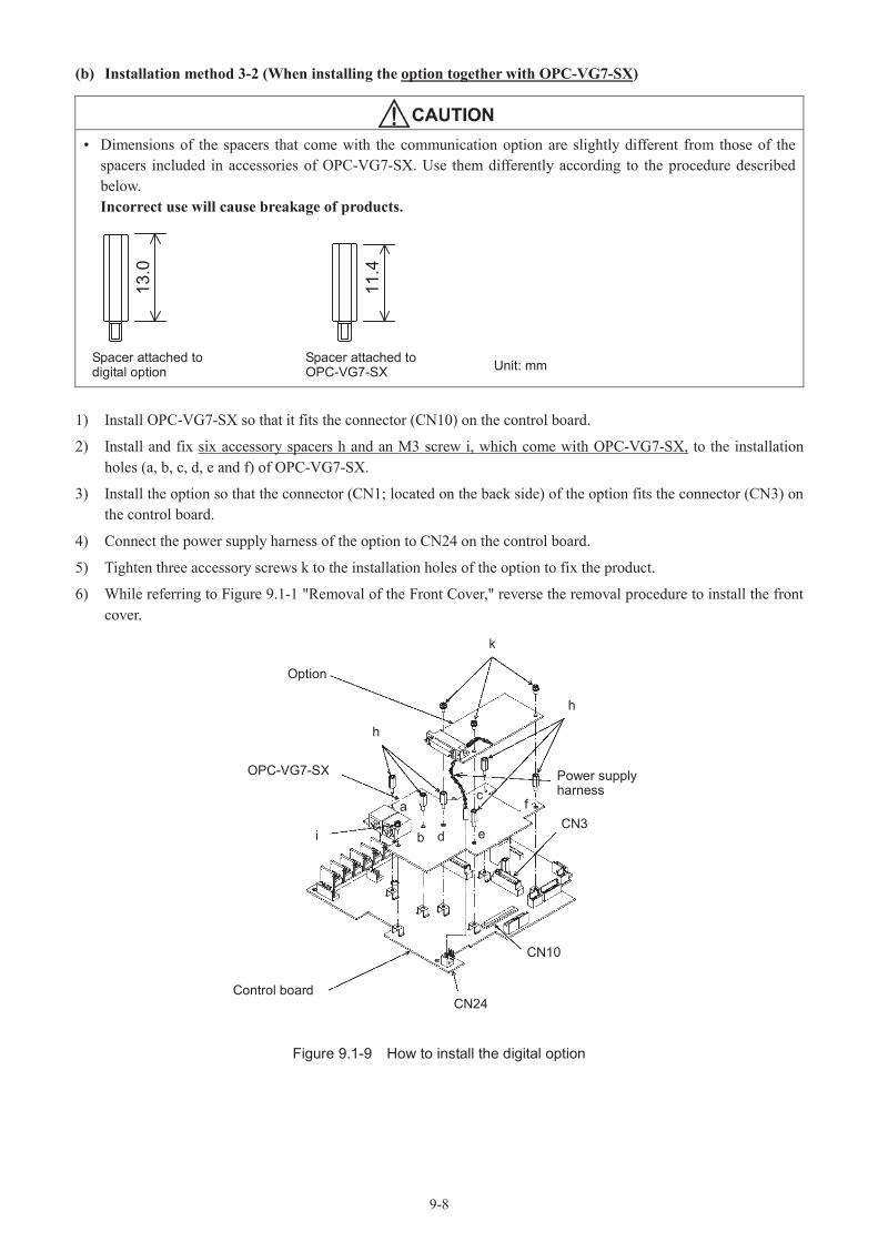
9-8
(b) Installation method 3-2 (When installing the option together with OPC-VG7-SX)
• Dimensions of the spacers that come with the communication option are slightly different from those of the spacers included in accessories of OPC-VG7-SX. Use them differently according to the procedure described below.Incorrect use will cause breakage of products.
13.0
11.4
1) Install OPC-VG7-SX so that it fits the connector (CN10) on the control board.
2) Install and fix six accessory spacers h and an M3 screw i, which come with OPC-VG7-SX, to the installation holes (a, b, c, d, e and f) of OPC-VG7-SX.
3) Install the option so that the connector (CN1; located on the back side) of the option fits the connector (CN3) on the control board.
4) Connect the power supply harness of the option to CN24 on the control board.
5) Tighten three accessory screws k to the installation holes of the option to fix the product.
6) While referring to Figure 9.1-1 "Removal of the Front Cover," reverse the removal procedure to install the front cover.
Figure 9.1-9 How to install the digital option
Spacer attached to digital option
Spacer attached to OPC-VG7-SX Unit: mm
CN24
CN10
CN3
k
Option
OPC-VG7-SX
Control board
Power supplyharness
h
h
cfa
b d ei

9-9
(5) How to install the SX option (OPC-VG7-SX)
Install this option according to the following procedure. To install this option together with another option, refer to pages describing the corresponding option.
a) Install the option so that it fits the connector (CN10) on the control board.
b) Install six spacers and an M3 screw, which come with this option, to the installation holes of the option as shown in the figure below.
c) While referring to Figure 9.1-1 "Removal of the Front Cover," reverse the removal procedure to install the front cover.
Figure 9.1-10 How to install OPC-VG7-SX
CN10
Control board
Modular jack
M3 screw
Spacer
OPC-VG7-SX

9-10
9.2 T-Link Option9.2.1 Product overview
Use this option to control RHC-D Series from Fuji's programmable logic controller MICREX-F or MICREX-SX (T-Link module).
Main applications
The following functions are provided with this option.
• Signal input such as RUN, X1 and RST
• Monitoring the operation status
• Running, converter shutoff, power running, regeneration, DC link voltage establishment, batch failure (alarm), T-Link writing error
• Operation data monitor (Input power, effective input current, effective input voltage, DC link current, power supply frequency)
• Check of each function code setting
• Referring to or changing each function codeFunction codes other than the S code may not be changed through communication.
[Limitations in installation]
Prohibited combination (Operation procedure error)
The T-Link option may not be used together with the CC-Link option. If installation is attempted, operation procedure error "Er6" is caused.
RHC-D
Empty
OPC-VG7-TL OPC-VG7-CCL
Note: This section describes merely the outline of each product. For detailed specifications, refer to the separate operation manual of the corresponding unit.

9-11
9.2.2 Model and specifications
Model
Description of model: OPC-VG7-TL
Name of option: TL T-Link interface option
Accessories: Spacer 3 piecesM3 crew 3 pieces
9.2.3 Specifications
• For the settings of the switches (RSW1, 2) on the option, read the following and give correct settings.Accidents may result.
Hardware specifications
Item SpecificationsName T-Link interface optionTransmission mode T-Link slave, I/O transmissionBaud rate 500kbpsNo. of occupied words for transmission
Use function code H11 "Transmission Format" to select.Total 16 words (8W + 8W): 8W for transmission from MICREX to RHC-D,
8W for transmission from RHC-D to MICREXTotal 8 words (4W + 4W): 4W for transmission from MICREX to RHC-D,
4W for transmission from RHC-D to MICREXTerminals TX+, TX-, SDRotary switches RSW1, 2 Address setting, 99W space
4W + 4W: Allows connection of 12 stations.8W + 8W: Allows connection of 6 stations.
Rotary switches RSW1, 2
Set the station number at rotary switches RSW1 and RSW2 on the option board.
12 3 4
5
79 86
0
12 3 4
5
79 86
0
RSW1 RSW2
RSW1: Upper order (tens digit)
RSW2: Lower order (ones digit)
• If two or more units are connected, give each unit a unique address.
• The factory shipment setting is station number 00 (RSW1: 0.RSW2: 0).
Software specifications
Item SpecificationsData updating cycle 4 ms
OperationOperation command Operation command, alarm reset command, X1 command
Operation state output Running, power running, regeneration, DC link establishment, converter shutoff, batch alarm signal
Function code
The function code assigned to the link number in the function code list can be referred to.Function codes other than the S code may not be changed through communication.
Option function codes H02, H03, H11
Protective functionsNetwork error: Er4* Minor failure: The Er4 alarm can be controlled with H02 and H03.* Serious failure: Immediate alarm
* Minor failure: Transmission error caused by noise or the like. If noise is not frequent, the Er4 alarm can be controlled with H02 and H03 to continue operation.
* Serious failure: Failure such as PLC shutoff and hardware failure.

9-12
9.2.4 External view
Description of terminal function
T1 T2 SD
(1) Terminal layoutTerminalTB11
(2) Description of terminals
Terminal symbol Name Description
T1T2SD
(Shield)
T-Link cable connection terminal For connection of T-Link cable
RSW1 RSW2
T1 T2 SDTB1
OPC-VG7-TL
5 40 53- 3.6
CN1
TBL1
RSW2
50 3-M3

9-13
9.2.5 Basic connection diagram
Refer to the installation method for built-in option before conducting wiring or connection work.
• Have connection conducted by professionals. If electric circuits must be touched during connection after power-on, turn the power supply side circuit breaker off (open) to avoid electric shock.Electric shock or fire may result.
• Even after the circuit breaker is turned off (to open the circuit), the smoothing capacitors remain charged; wait until the CHARGE lamp of the converter is unlit and measure the DC voltage of the converter with a multimeter or the like to check that the voltage has dropped below the safe level.Electric shock may result.
• Do not use a product having a broken or missing part.Injury may result.
• Do not perform inappropriate work during installation or removal of the product.Breakage may result.
Basic connection diagram
The example of basic connection diagram is shown on the next page. Follow the precautions below when connecting.
[Precautions about connection]
(1) Use the T-Link cable specified below.
• Twisted pair cable made by Furukawa Electric Co., Ltd. ... CPEV-SB, ø 0.9 x 1 pair• Twisted pair cable made by Furukawa Electric Co., Ltd. ... KPEV-SB, 0.5mm2 x 1 pairFor the specifications of the above cables, refer to the reference data of MICREX.
(2) Connect a 100 (terminator attached to the P capsule at each of both ends of T-Link.
(3) Connect the T-Link cable to form a single loop as shown in the basic connection diagram. Correct transmission is impossible with cable branches.
(4) Route the T-Link cable as far away from main circuit wiring of the converter main body and other power cables as possible (at least 30 cm) to avoid malfunction caused by noise; never route these cables in the same duct.

9-14
Example of basic connection diagram
MICREXP capsule
T1
T2
SD
T1T2SD
DI capsule
T1T2SD
L1/R
L3/T
L2/S
N
P
RHC-D
OPC-VG7-TL
T1
T2
SD
Terminationresistor
Power supply to inverter
G
Station address 20
Station address 10
Stationaddress 50
DI capsule
Terminationresistor
Twis
ted
pair
cabl
es w
ith s
hiel
ded

9-15
9.2.6 Function codes
• Wrong function code data may cause danger. Check the data again after finishing data entry and writing.Accidents may result.
No.Name of parameter
Setting range Description of setting
Name Indication at keypad
H02
Operation selection upon error occurrence (Er4 upon minor failure)
MODE ON ER
0 Immediate forcible stop upon occurrence of minor failure(Er4 trip: Output shutoff)
1
After minor failure, operation continues for the timer interval (upon a communication error, the operation command sent in the immediately previous session is held). After the timer interval, forcible stop (Er4 trip: output shutoff)If communication is restored in the timer interval, the converter follows the command sent via communication. However, forcible stop after timer interval.
2
After occurrence of minor failure, operation continues for the timer interval (upon minor failure, the operation command sent in the immediately previous session is held). If the minor failure is not removed after the timer interval, forcible stop.If communication is restored in the timer interval, normal operation continues according to the command sent via communication.
3
Even if minor failure occurs, an alarm (Er4) is not developed. In the minor failure state, the operation command having been sent in the immediately previous session is held. Upon restoration of communication, normal operation continues according to the command sent via communication.
H03 Timer interval TIMER LINK0.00to
20.00s
Operation time timer setting for occurrence of minor failure.Valid if H02 = "1" or "2."
H11 TL transmission format 4W/8W SEL 0, 1 0: Format 1 (Standard format 4W + 4W)
1: Format 2 (8W + 8W)
• The factory shipment settings are: H02 = 3 and H03 = 2.00• For accessible function codes, refer to the function code list.
9.2.7 Protective operation
Minor failure and serious failure
There are two levels in the failure of the T-Link option: minor and serious.Upon occurrence of a failure, the converter issues Er4 "Network Error."
Item Minor failure Serious failure
Cause
Noise added to communication cableDuplicate address(Wrong setting of RSW1, 2)
Broken communication cableShutdown of MICREX (PLC)
Failure of T-Link option hardware (breakage or fault)
Resetting methodRemove the cause of the alarm (restore communication to automatically remove) and give a reset command (keypad panel, [RST] or resetting through communication).
Remove the cause of the failure of the hardware and reset the power.
Control of failure status
The alarm occurs only when operation commands are given through the T-Link.The alarm can be controlled with function codes H02 and H03.
Momentary Er4 alarm

9-16
9.3 SX Bus Option9.3.1 Product overview
This is an interface card (OPC-VG7-SX) for connecting the RHC-Dseries with Fuji's MICREX SX Series programmable logic controller via an SX bus. Using programs of MICREX-SX, you can start automatic operation, monitor, or change or check function code settings necessary for operation.
Main applications
The following functions are provided with this option.
• Signal input such as RUN, X1 and RST• Monitoring the operation status
Running, converter shutoff, power running, regeneration, DC link voltage establishment, batch failure (alarm), SXwriting error
• Operation data monitor (Input power, effective input current, effective input voltage, DC link voltage, power supply frequency)
• Referring to or changing each function codeFunction codes other than the S code may not be changed through communication.
[Limitations in installation]
Prohibited combination (Operation procedure error)
The SX option cannot be installed together with the CC-Link option. As well, no other option card can be connected to the connector (CN2) for eight-bit bus options on the left side.
If installation is attempted, operation procedure error "Er6" is caused.
Option card
RHC-D
OPC-VG7-SX
RHC-D
OPC-VG7-SX
OPC-VG7-CCLEmpty Empty
[System Definition]Choose the following, when you add a module in the programming support tool expert (D300Win).
Module attribute type : Individual type moduleModule group type : ConverterOutline specification : RHC-C RHC-C(S) or RHC-C/MONITOR RHC-C(M)
Note: This section describes an outline of each product only. For detailed specifications, refer to the operation manual of the corresponding unit

9-17
9.3.2 Model and specifications
Model
Description of model: OPC-VG7-SX
Name of option: SX SX bus interface option
Accessories: Spacer 6 piecesM3 screw 1 pieces
9.3.3 Specifications
• For the settings of the switches RSW1, 2 on the option, read the following and give correct settings.Accidents may result.
• Give switch (RSW1 and 2) settings on the option after turning off the converter.Electric shock may result.
Hardware specifications
Item SpecificationsName SX bus interface optionTransmission mode SX bus slave, I/O transmissionBaud rate 25 MbpsNumber of occupied transmission words
Standard format (8 words: 4W + 4W) ... Without T-Link optionMonitoring format (16 words: 4W + 12W) ... With T-Link option
Terminal/bus cable Special IN and OUT cables for SX bus *NP1C-P3 (0.3 m) - NP1C-25 (25 m)Rotary switch RSW1, 2 Station number setting; an arbitrary station number ranging from 1 to 238 can be
assigned.State indication LED (RUN and ERR)
State of own station (run or error) is indicated with an LED.
Rotary switches RSW1, 2
Set the station number, using rotary switches RSW1 and RSW2 on the option board. "RSW1" corresponds to the upper four bits, and "RSW2" corresponds to lower four bits. Read the setting in a decimal as a station number of the SX bus.
Example: Station number "194" is C2H. Set "C" at RSW1 and "2" at RSW2.
012 3456789ABCDE
F 012 3456789ABCDE
F
RSW1 RSW2
• Keep consistency with the SX bus station number specified in the system definition of MICREX-SX. Because the address assigned by MICREX-SX is the actual SX bus station number, the setting of this rotary switch may be different.
• If two or more units are connected, give each unit a unique address.• The factory shipment setting is station number 00 (RSW1: 0. RSW2: 0).• The RSW1 and RSW2 settings are recognized upon power-up or resetting of the SX
bus (MICREX-SX).

9-18
Software specifications
Item Specifications
Data updating cycle Minimum 1 ms
OperationOperation command Operation command, alarm reset command, X1 commandOperation state output
Running, power running, regeneration, batch alarm signal, etc.
Function codeThe function codes assigned to the link number in the function code list can be referred to.Function codes other than the S code may not be changed through communication.
Option function codes H02, H03
Protective functionsNetwork communication error (Er4: Network error)* Minor failure: The Er4 alarm can be controlled with H02 and H03.* Serious alarm: Immediate alarm
* Minor failure: Signal noise or the like. If noise is not frequent, the Er4 alarm can be controlled with H02 and H03 to continue operation.
* Serious failure: Serious failure such as hardware failure.
Note: The data refreshing period depends on the SX bus cycle of MICREX-SX and the task period of the application program.

9-19
9.3.4 External view
DA
TE
MA
DE
IN JA
PA
N
43
21
B
40 56.5
5 40
111.5 13.5
27 14 39.5
2772
51
715
65
150
1537
.510
.5
CN3
6.6
CN1
OPC-VG7-SX
10 11
38
- 4.0
12
D
E
AC
A
C
65
4
EP-4304C- CN
O.
1410
7416
10
RSW1 RSW2FG
CN2 CN3
OUTIN
13.64
CN1
M3
RSW2
FG
Connector CN2, CN3
OPC-VG7-SXEP-4304C-C
RSW1FG
OUTIN
RSW2
CN3CN2
0
8
4C
A
2E
6
1
9
5
D
F
7
3
B
0
8
4C
A
2E
6
1
9
5
D
F
7
3
B
RU
NER
R
• Keep the FG terminal unconnected. To prevent intrusion of noise, do not connect a grounding wire to the terminal.
• This printed option board is not equipped with an SX bus cable (special) or terminator connector. Prepare a cable having the desired length for the distance of bus connection. Connect a terminator connector on one of the connectors if the board is located at either end of the SX bus.
• The terminator connector is included in accessories of the MICREX-SX CPU module.
M3 screw

9-20
9.3.5 Basic connection diagram
• Have connection conducted by professionals. If electric circuits must be touched during connection after power-on, turn the power supply side circuit breaker off (open) to avoid electric shock.Electric shock or fire may result.
• Even after the circuit breaker is turned off (to open the circuit), the smoothing capacitors remain charged; wait until the CHARGE lamp of the converter is unlit and measure the DC voltage of the converter with a multimeter or the like to check that the voltage has dropped below the safe level.
• Because the power of the SX bus is supplied from the power module of the PLC, check that MICREX-SX and the converter are turned off before installing or removing this option.Electric shock may result.
• Do not use a product having a broken or missing part.Injury may result.
• Do not perform inappropriate work during installation or removal of the product.Breakage may result.
The example of basic connection diagram is shown on the next page. Observe the following precautions when connecting.
[Precautions about connection]
(1) Be sure to use the special cable for the SX bus cable.Model: NP1C-P3 (cable length 0.3m) to NP1C-25 (cable 25m)For the cable specifications, refer to the reference data of MICREX-SX.
(2) Check that MICREX-SX and the converter are turned off before starting work.
(3) Connect the terminator plug, which is attached to the MICREX-SX CPU module, at each of both ends of the SX bus.
(4) Route the SX bus cable as far away (at least 30cm) from the main circuit cables of the converter main body and other power cables as possible to avoid malfunction caused by noise. Never route them in the same duct.
(5) Connect the SX bus cable from OUT of the base board to IN. With OUT-OUT or IN-IN connection, communication fails and the system does not function. Route cables so that the bending radius of the cable becomes larger than 50mm.

9-21
Example of basic connection diagram
SX
+ +
+
+
+
+
IN
OUT
SX bus terminator plug
SX bus terminator plug
SX bus expansion cable
The maximum total length of the SX bus expansion cable is 25 m.
P P(+)N N(-)
E
E(G)
L1/RL2/SL3/T
RHC-D Inverter
OP
C-V
G7-
SX
IN
PN
E
E(G)
L1/RL2/SL3/T
RHC-D Inverter
OP
C-V
G7-
SX
IN
P(+)N(-)
OUT
OUT
SX bus expansion cable
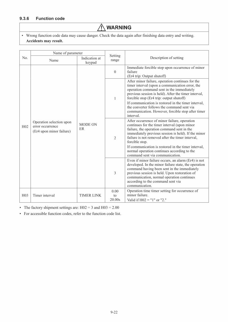
9-22
9.3.6 Function code
• Wrong function code data may cause danger. Check the data again after finishing data entry and writing.Accidents may result.
No.Name of parameter
Setting range Description of setting
Name Indication at keypad
H02Operation selection upon error occurrence (Er4 upon minor failure)
MODE ON ER
0Immediate forcible stop upon occurrence of minor failure(Er4 trip: Output shutoff)
1
After minor failure, operation continues for the timer interval (upon a communication error, the operation command sent in the immediately previous session is held). After the timer interval, forcible stop (Er4 trip: output shutoff)If communication is restored in the timer interval, the converter follows the command sent via communication. However, forcible stop after timer interval.
2
After occurrence of minor failure, operation continues for the timer interval (upon minor failure, the operation command sent in the immediately previous session is held). If the minor failure is not removed after the timer interval, forcible stop.If communication is restored in the timer interval, normal operation continues according to the command sent via communication.
3
Even if minor failure occurs, an alarm (Er4) is not developed. In the minor failure state, the operation command having been sent in the immediately previous session is held. Upon restoration of communication, normal operation continues according to the command sent via communication.
H03 Timer interval TIMER LINK0.00to
20.00s
Operation time timer setting for occurrence of minor failure.Valid if H02 = "1" or "2."
• The factory shipment settings are: H02 = 3 and H03 = 2.00• For accessible function codes, refer to the function code list.

9-23
9.3.7 Protective operation
Minor failure and serious failure
There are two levels in the failure of the SX bus option: minor and serious.Upon occurrence of a failure, the converter issues Er4 "Network Error."
Item Minor failure Serious failure 1 Serious failure 2
Cause• Communication data error
caused by noise intruding into communication cable
• All masters shutdown• Detection of broken wire• SX bus power shutdown
• Failure of option hardware• Improperly installed option
Resetting methodRemove the cause of the alarm (restore communication to automatically remove) and give a reset command (keypad panel, [RST] or resetting through communication).
After removing the cause of the alarm, turn the converter off then on again.
Control of failure status
Alarm detection is performed only while operation commands are given through the SX bus.The alarm can be controlled, using function codes H02 and H03.
Er4 alarm is caused immediately upon a serious failure.
Communicationerror codedisplayed atkeypad panel
1 2 3
Note: In serious failure category 1, the CPU must be reset, too, according to some states of the CPU of the MICREX-SX.
The communication error code in a minor or serious failure can be checked on the communication state screen in maintenance data at the keypad panel. To reach the communication state screen, press the PRG key on the operation mode screen to call up the menu screen, use the or key to move the arrow on the left end of the screen to "5.Maintenance," and press the FUNC/DATA key. Next, press the key three times to display the screen shown below.
NRK =xxxxxNRR =xxxxx xxNRO =xxxxx xxNRL =xxxxx xx
-: No error1: Minor failure2: Serious failure 13: Serious failure 2

9-24
9.4 CC-Link Option9.4.1 Product overview
Use this option to control the RHC-D via the CC-Link from the CC-Link master(CC-Link compliant sequencer).
Main applications
The following functions are provided with this option.
• Signal input such as RUN, X1 and RST
• Monitoring the operation statusRunning, converter shutoff, power running, regeneration, DC link voltage establishment, batch failure (alarm), CC-Link writing error
• Operation data monitor (Input power, effective input current, effective input voltage, DC link voltage, power supply frequency)
• Referring to or changing each function codeFunction codes other than the S code may not be changed through communication.
[Limitations in installation]
Prohibited combination (Operation procedure error)The CC-Link option cannot be installed together with the T-Link option card or SX bus interface card. If installation is attempted, operation procedure error "Er6" is caused.
RHC-D
OPC-VG7-TL OPC-VG7-CCL
RHC-D
OPC-VG7-SX
OPC-VG7-CCL
Note: This section describes merely the outline of each product. For detailed specifications, refer to the separate operation manual of the corresponding unit.

9-25
9.4.2 Model and specifications
Model
Description of model OPC-VG7-CCL
Name of option: CCL CC-Link interface option
Accessories: Spacer 3 piecesM3 screw 3 pieces
9.4.3 Specifications
• For the settings of the switches (RSW1, 2, 3) on the option read the following and give correct settings.Accidents may result.
• Turn the inverter off before setting the switches (RSW1, 2, 3) on the option.Electric shock may result.
Hardware specifications
Item SpecificationsName CC-Link interface optionStation type Remote device stationNo. of connected stations Max. 42 stations; various models can be connected.No. of occupied stations Fixed to occupy one station (standard profile). Set "0" at H11.Connection terminal block 5 terminal blocks (M3 x 5 screws)Connection cable Special cable for CC-Link compatible with CC-Link Ver. 1.10
For details, refer to the catalog of CC-Link or web home page of CC-LINK organization(http://www.cc-link.org/).
Rotary switches RSW1, 2 Station number setting. An arbitrary station number between "1" and "64" can be assigned.
Rotary switch RSW3 Communication speed (baud rate) setting. 10M / 5M / 2.5M / 625K / 156KbpsOperation state display LED
L.RUN Lit upon reception of correct refresh data. Unlit after interruption of certain interval.L.ERR Lit upon communication error of own station. Blinks upon operation of rotary switch during power-on.SD Lit during transmission.RD Lit during reception
Rotary switches RSW 1 and 2
Set the station number of the converter between "1" and "64" before turning the converter on.
12 3 4
5
79 86
0
12 3 4
5
79 86
0
RSW1 RSW2STATION No.
RSW1: Upper order (tens digit)
RSW2: Lower order (ones digit)
• Do not change the station number after the converter is turned on.Even if the station number is changed during power-on, datacommunication cannot be made with the new station number.
• If a duplicate station number is set or the station number is out of the setting range, correct communication cannot be made. (TheL.ERR LED lights up.)
• Give continuous station number in the order of connection.(Designate a "reserved station" for the skipped station number.

9-26
Transmission baud rate setting switch RSW3
Before turning on the converter, specify the transmission baud rate in the range from "0" to "4."
12 3 4
5
79 86
0
RSW3B.RATE
Baud rate specificationsNo. Baud rate0 156 Kbps (Initial value)1 625 Kbps2 2.5 Mbps3 5 Mbps4 10 Mbps
5 to 9 Setting error (The L.ERR LED lights up.)
Operation state display LED
The link state of CC-Link can be checked at four LEDs.
Specifications of operation state display LED
StateOperationL.RUN L.ERR SD RD
Correct communicationCorrect communication with frequent CRC error due to noiseFailure to respond due to CRC error of received dataNo data destined to own stationCRC error in refresh reception in spite of response to pollingCRC error in data destined to own stationNo data destined to own station or failure to receive data due to noiseIllegal baud rate or station address setting
(0.8s period)Baud rate or station address setting changed in the middle
Before link startFailure to receive data due to broken wire or the like, shutdown, hardware reset, occurrence of Er3, failure in power unit
: Lit, , Unlit, : Blink (The LED may erroneously seem to be lit at some transmission speeds.)
Note 1: If the LEDs are lit in a pattern other than those listed above, a hardware error is probable. Contact us.
Software specifications
Item Specifications
Ope
ratio
n Operation command Operation command, alarm reset command, X1 commandOperation state output Running, power running, regeneration, bit data such as batch alarm signal
Option function codes H02, H03, H11 (fixed at "0"): Factory shipment setting is "0."
Protective functions
Er4: Network error* Minor failure: Communication line error (Use function codes H02 and H03 to control
Er4.)* Serious failure: Option error (The stopping method can be selected with function
codes H02 and H03.)* Minor failure: If noise is not frequent, the Er4 alarm can be controlled with function codes H02 and H03 to continue
operation.* Serious failure: Failure such as hardware failure.

9-27
9.4.4 External view
Terminal block
TB1
FG SLD DG DB DA
Specifications of terminal block
Name of terminal Description RemarksDA
For communication data -DBDGSLD For connection of shield of cable SLD and FG are
connected inside the unit.FG For grounding

9-28
9.4.5 Basic connection diagram
• Have connection conducted by professionals. If electric circuits must be touched during connection after power-on, turn the power supply side circuit breaker off (open) to avoid electric shock.Electric shock or fire may result.
• Even after the circuit breaker is turned off (to open the circuit), the smoothing capacitors remain charged; wait until the CHARGE lamp of the converter is unlit and measure the DC voltage of the converter with a multimeter or the like to check that the voltage has dropped below the safe level.Electric shock may result.
• Do not use a product having a broken or missing part.Injury may result.
• Do not perform inappropriate work during installation or removal of the product.Breakage may result.
The basic connection diagram is shown below. Observe the following precautions when connecting.
[Connection precautions]
(1) Use the special cable for CC-Link.
Never use soldered cables; otherwise connections may be disconnected and broken wires may be caused.
(2) Use terminators attached to the programmable logic controller.
(3) For the maximum number of connected stations, refer to the number of connected stations in the hardware specifications.
To connect one converter
CC-Link master Converter
DADBDG
SLD
L1/R PL2/S NL3/T
OPC-VG7-CCLDADBDGSLDFG
Power supply Inverter

9-29
If two or more converters are connected················ For the allowable number of connected stations, refer to the hardware specifications.
DA
DB
DG
SLD
FG
DA
DB
DG
SLD
FG
DA
DB
DG
SLD
FG
MasterConverter
OPC-VG7-CCL
Twisted paircables with
shielded
Terminationresistor
ConverterOPC-VG7-CCL
Twisted paircables with
shielded
Terminationresistor
9.4.6 Protective operation
Minor failure and serious failure
The CC-Link option has two levels in the failure of the CC-Link option: minor and serious. Upon occurrence of a failure, the converter issues Er4 "Network Error."
Minor failure and serious failure
Item Minor failure(Action upon faulty communication line)
Serious failure(Action upon faulty option)
Cause of occurrence
• Master shutdown• Detection of broken wire• Error in communication data (Noise
intruding to communication cable, etc.)
• Option hardware error• Option installation fault
Resetting method
After removing the cause of the alarm (automatically removed upon restoration of communication), give a reset command (Note 1).
Turn the converter off and remove the cause of the alarm, then turn the converter on.
Control of alarm output
• The error is detected only in the CC-Link operation mode.
• The alarm output method upon detection of an error can be controlled with function codes H02 and H03.
Momentary Er4 alarm
Communication error code 01 02
Action upon minor failure (communication line error)
H02 setting
Upon communication line error Communication error after H03 time Upon removal of communication errorOperation
state Indication Batch failure output
Operation state Indication Batch failure
outputOperation
state Indication Batch failure output
0 RUN to OFF Immediate Er4 ON Output Continuation
of stoppageContinuation
of Er4Continuation
of output
1 RUN to OFF Regular display No output OFF Er4 ON Output Continuation
of stoppageContinuation
of Er4Continuation
of output
2 RUN to OFF Regular display No output OFF Er4 ON No output Restart Regular
display No output
3 RUN to OFF Regular display No output Restart Regular
display No output

9-30
Action upon serious failure (option error)
H02 setting
Upon faulty option error Communication error after H03 time Upon removal of faulty option errorOperation
state Indication Batch failure output
Operation state Indication Batch failure
outputOperation
state Indication Batch failure output
0 RUN to OFF Immediate Er4 ON Output Continuation
of stoppageContinuation
of Er4Continuation
of output
1 RUN to OFF Immediate Er4 ON Output Continuation
of stoppageContinuation
of Er4Continuation
of output
2 RUN to OFF Immediate Er4 ON Output Continuation
of stoppageContinuation
of Er4Continuation
of output
3 RUN to OFF Immediate Er4 ON Output Continuation
of stoppageContinuation
of Er4Continuation
of output
Note 1: "To give a reset command" means to reset the converter in one of the following methods.* RESET key input at keypad panel* Give a digital input to error reset [RST] terminal.* Reset command input via communication
Note 2: Upon minor failure with H02 being "0" or "1," the converter can be reset even if the cause of alarm is not removed. Upon minor failure with H02 being "2" or upon serious failure, the converter is not reset until the cause is removed.
Note 3: The communication error code of minor or serious failure can be checked at the keypad on the maintenance data communication state screen.

9-31
9.5 DIO Option9.5.1 Outline of product
Use option OPC-VG7-DIO to add maximum eight DO points for each piece. The digital input is not added.
Major applications
Use switch SW2 provided on the option to switch between DIOA and DIOB.
Select "DIOA" to use eight DO points. Through this, these points can be used for the RUN, life forecast, alarm description and other operation state monitoring signals. They may not be used if "DIOB" is selected.
Photocoupler isolation
The output interface is isolated with photocouplers. The signal cable can be extended up to several tens of meters.
Sink/source
The output interface can be connected with either the sink or source power supply.
Generally speaking, the sink interface is usually used in Japan and United States.
With this specification, the active signal is indicated with 0V.
The source interface is frequently used in Europe. With this specification, the active signal is indicated with a positive voltage.
I/O check function
The ON/OFF state of each output signal can be monitored at the keypad panel or through communications (RS485,T-Link or SX bus).
[Limitation in installation]
Prohibited combination (operation procedure error)
Two DIOA boards may not be installed simultaneously. Or the DIOB setting may not be given to two boards simultaneously.
If prohibition is neglected, operation procedure error "Er6" will be caused.
OPC-VG7-DIO
(DIOA)
RHC-D
Empty
OPC-VG7-DIO(DIOA)

9-32
9.5.2 Model and specifications
Model
Model nomenclature: OPC-VG7-DIO
Name of option: DIO - digital output option
Accessories: Plug (model: 10136-3000VE, Sumitomo 3M Limited; 36 pins)Housing (model: 10336-52F0-008, Sumitomo 3M Limited; 36 pins)Spacer: 3 piecesScrew (M3): 3 pieces
9.5.3 Specifications
• If the setting of the switch (SW2) provided on the option is wrong, the system fails to function correctly. Read the following and give a correct setting.Accidents may result.
Hardware specifications
Item SpecificationsName DIO expansion cardModel OPC-VG7-DIO
Out
put No. of contacts 8 points (Y11-Y18)
Ground CME; common ground for both points
CircuitCircuit isolated with photo-relays (50 mA DC max., 28 V max.)Capable of sink/source connection (sink/source)
Power supply24 VThe power is supplied from the printed circuit board of the main body. Connect the power supply harness to the connector provided on the main body.
1) Switch on printed circuit board
Refer to the figure to the right for approximate locations of switches in the view from the front of the printed circuit board.
Either the sink or source power supply can be connected to theoutput circuit.
Switch Factory shipment stateSW1 SINKSW2 DIOA
SW2
DIOADIOB
EP-4223-
SINKSOURCE
Connector
SW1
OPC-VG7-DIO
Power supply harness

9-33
2) Output circuit
Either the sink or source power supply can be connected. Because the CME common is common for all contacts (Y11 to Y18), simultaneous connection of sink and source types is prohibited. To connect a control relay, connect a surge absorber diode at both ends of the exciting coil as shown in the figure below.
CMESource voltage: 28VmaxPassing current: 50mAmax
Y11
CME is isolated from CM.
CMESource voltage: 28VmaxPassing current: 50mAmax
Y11
CME is isolated from CM.
3) Others
• If the protective function of the converter is activated, refer to Section 7.3 "Troubleshooting" described for the converter to remove the cause of the fault and restart.
• For the maintenance and inspection items, refer to Section 8.
Software specifications
Item Specifications
Output data Refreshment interval
Minimum 0.5 ms interval.Some output functions may be refreshed at an interval longer than 0.5 ms.
9.5.4 Dimensioned drawing
Printed circuit board

9-34
AccessoriesPlug Housing
21.59
1.27
27.8
9.1
7.5
15°
Pin 1
Pin 19
3M 1013
632.2
12.7
43.5
39.0
23.8
32.2 18.0
12.7
14.0
17.0
Model: 10136-3000VE Model: 10336-52F0-008Specifications: Sumitomo 3M Limited; 36 pins Specifications: Sumitomo 3M Limited; 36 pins
* The plug and housing come with the product.

9-35
9.5.5 Basic connection diagram
Basic connection diagram (DIOA)Table 9.5-1
Pin No. Name Function Pin
No. Name Function
19 2120 22
23 2524 26
27 2928 30
31 3332 34
1 32 4
5 76 8
9 1110 12
13 1514 16
3536
1718
<View from soldered terminal side of plug>
1 CM Common (M24) 13 Y11 Control output Y112-5 - Not connected 14 Y12 Control output Y126 CM Common (M24) 15 Y13 Control output Y137-12 - Not connected 16 Y14 Control output Y14
17 Y15 Control output Y1518 CME Output common19-30 - Not connected31 Y16 Control output Y1632 Y17 Control output Y1733 Y18 Control output Y1834, 35 - Not connected36 CME Output common
OPC
-VG
7-D
IO,S
W2
=D
IOAInverterRHC-DMain power supply
3-phase50/60Hz
E
P
NL1/R
L2/S
L3/T
[13]
[14]
[15]
[16]
[17]
[31]
[32]
[33]
Y11
Y12
Y13
Y14
Y15
Y16
Y17
Y18
[18]
[P24]
[M24]
[P24]
[M24]CN24
[CME]

9-36
9.5.6 Function codes
• Modification of the function code data may cause dangerous state. To be safe, check the data after entering and writing it.Accidents may result.
DIOA output
The following functions can be assigned to eight digital outputs (Y11 through Y18).Give the setting at function codes E06 through E13.
Setting Function Symbol Setting Function Symbol0 Running [RUN] 8 Current limit forecast [CUR]1 Ready [RDY] 9 Restart after momentary
power failure[U-RES]
2 Current limiting [IL] 10 Source frequency synchronization
[SY-HZ]
3 Life forecast [LIFE] 11 Alarm description [AL1]4 Heat sink overheat
forecast[PRE-OH] 12 Alarm description [AL2]
5 Overload forecast [PRE-OL] 13 Alarm description [AL3]6 Power running [DRV] 14 Option DO [OPT-DO]7 Regenerating [REG]
9.5.7 Check function
(1) Option installation check
You can check whether the DIO option is installed or not, on the keypad panel.
On the operation mode screen, switch to the program menu screen and select "4. I/O Check." There are total five I/O check monitor screens; use the or key to scroll the screen to go to the corresponding DIO option screen. In the system with DIOA setting, the square on the LCD screen changes to solid black square as shown in the figure to the right.
As well, the output state screen is displayed for the system equipped with a DIOA option.
(2) I/O check
The digital output state of the DIO option can be checked at the keypad panel of the converter. On the operation screen, switch to the program menu screen and select "4. I/O check." There are total five I/O check monitor screens; use the or key to scroll the screen to go to the corresponding DIO option digital output state screen. The screen shows the DIO digital output state. The active contact is indicated with a solid black square .
* There are some screens not displayed with the system not equipped with the option. The number of screens is five, including those not displayed.
DIOA AIOTLINK SICCL SXFIELD TRACE
Y11 Y15Y12 Y16Y13 Y17Y14 Y18

9-37
9.6 AIO Option9.6.1 Outline of product
The analog output built in the main body of the converter is only one point [A01]. Use option OPC-VG7-AIO to add two points [A04] and [A05]. Analog inputs are not added.
Major applications
The same control functions as those of the analog output built in the main body of the converter become available.
Relieving the shortage in analog output
Use the option to add analog output points.
This expansion card becomes necessary if the analog output terminal built in the main body of the converter is already used and more analog outputs are necessary.
I/O check function
The analog output signal statuses can be monitored on the I/O check screen of the keypad panel.
[Limitation in installation]
Available combination
The AIO option can be installed at the right side connector (CN3) when facing the control printed circuit board. Only one analog option can be installed.
OPC-VG7-AIO
RHC-D
Empty
Empty

9-38
9.6.2 Model and specifications
Model
Model nomenclature: OPC-VG7-AIO
Name of option: AIO; analog output option
Accessories: Spacers 3 piecesScrews (M3) 3 piecesPower supply harness (for 15V power supply) 1 piece
9.6.3 Specifications
• The adjusters (VR1 and VR2) inside the option are adjusted before shipment from the factory. Keep away from the adjusters.Accidents may result.
Hardware specifications
Item SpecificationsName AIO expansion cardModel OPC-VG7-AIOOutput No. of terminals 2 points ([AO4], [AO5])
Ground [M] (Connected with terminal [M] in the control printed circuit board)Circuit Output voltage: 0 to 10VDC, resolution: 12 bits
Output impedance: Min.3kPower supply 15V
Supplied from control printed circuit board. Connect the power supply harness to CN12.
Software specifications
Item SpecificationsOutput data Refreshment
interval1 ms
Function assignment
Can be configured with function codes E19 and E20

9-39
9.6.4 Dimensioned drawing
A B
54
32
1
1 3
CN22 12930CN1
OP
C-V
G7-
AIO
EP
-423
1-
3- 3.65
5
5 4050
40
125
85
VR
2V
R1
AI3 AI4 M MTB1 Ao4 Ao5
CN3
15
61
CN1CN2
VR2CN3
TB1
10.3
11.5
6
15.4
11.5

9-40
9.6.5 Basic connection diagram
• Have connection done by professional personnel. If electric circuits may be touched during connection work after the power is supplied, turn the main circuit breaker off to avoid electric shock.Risk of electric shock and fire
• Even if the circuit breaker is turned off, the smoothing capacitor remains charged. Wait until the CHARGE lamp of the converter is turned off, and check that the DC voltage of the converter has dropped below the safe voltage, using a multimeter or the like.Risk of electric shock
• Do not use the product if some parts are damaged or missing.Risk of injuries
• Do not conduct incorrect work during installation or removal of the product.Risk of breakage
P(+)
N(-)
InverterRHC-D
L1/R
L3/T
L2/S
[AO4]
[AO5]
[M]
[CN2]
[CN12]
OP
C-V
G7-
AIO
Analog output 4Analog output 5
E(G)
Main power supply3-phase50/60Hz
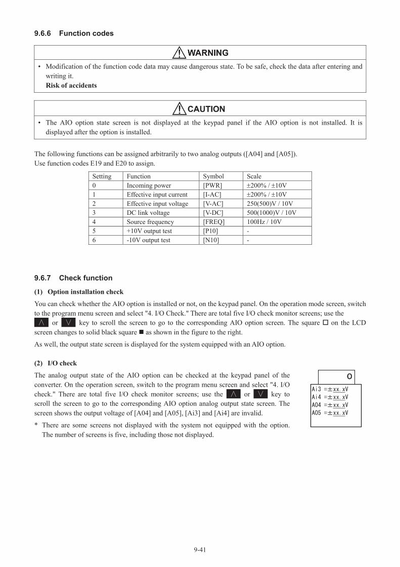
9-41
9.6.6 Function codes
• Modification of the function code data may cause dangerous state. To be safe, check the data after entering and writing it.Risk of accidents
• The AIO option state screen is not displayed at the keypad panel if the AIO option is not installed. It is displayed after the option is installed.
The following functions can be assigned arbitrarily to two analog outputs ([A04] and [A05]).Use function codes E19 and E20 to assign.
Setting Function Symbol Scale0 Incoming power [PWR] 200% / 10V1 Effective input current [I-AC] 200% / 10V2 Effective input voltage [V-AC] 250(500)V / 10V3 DC link voltage [V-DC] 500(1000)V / 10V4 Source frequency [FREQ] 100Hz / 10V5 +10V output test [P10] -6 -10V output test [N10] -
9.6.7 Check function
(1) Option installation check
You can check whether the AIO option is installed or not, on the keypad panel. On the operation mode screen, switch to the program menu screen and select "4. I/O Check." There are total five I/O check monitor screens; use the
or key to scroll the screen to go to the corresponding AIO option screen. The square on the LCD screen changes to solid black square as shown in the figure to the right.
As well, the output state screen is displayed for the system equipped with an AIO option.
(2) I/O check
The analog output state of the AIO option can be checked at the keypad panel of the converter. On the operation screen, switch to the program menu screen and select "4. I/O check." There are total five I/O check monitor screens; use the or key to scroll the screen to go to the corresponding AIO option analog output state screen. The screen shows the output voltage of [A04] and [A05], [Ai3] and [Ai4] are invalid.
* There are some screens not displayed with the system not equipped with the option. The number of screens is five, including those not displayed.

9-42
9.7 SI Option
9.7.1Product overviewLarge-capacity converter drive
The main circuit insulation system parallel system for the RHC-D Series PWM converter is used in combination with an insulation transformer to insulate the primary power supply, and connects to multiple units (2 multiplex, 3 multiplex) to drive the converter. This option applies to load sharing for all converters, and facilitates drive with up to a 6 multiplex system.
Current sharing
To drive an inverter with multiple converters, it is necessary to equip each converter with an optical link option. With this optical link, current commands allotted to converters are conveyed instantly. Current is controlled (feedback control) for each converter, enabling operation with load sharing determined by the drive capabilities of each converter.
Parallel/single system switching function
In cases such as where a single converter malfunctions when performing parallel system drive, parallel system operation can be canceled and switched to standard single system operation with the parallel/single system switching function.
[Installation restrictions]
It is not possible to equip converters with two SI options at the same time. By doing so, operation procedure error "Er6"will occur.
9.7.2 Model
Model: OPC-VG7-SI
Accessories: Spacer x 3Screw (M3) x 3Optic fiber cable x 1 (for transmission/receipt)

9-43
9.7.3 Specifications
Control specifications
Item SpecificationsApplicable converter capacity
MD (CT) spec. (up to 4,800kW: 6 multiplex), LD (VT) spec. (up to 6,000kW: 6 multiplex)
Parallel control method AVR constant control with DC ACR minorOutput voltage 640 - 710 VDCCarrier frequency 5kHzInput power 380 - 440 V 50Hz, 380 - 460 V 60Hz * The capacity must be reduced if less than 400 V.
Input power factor
Approx. 0.99 (with 100% load)The power supply power factor drops to approx. 0.95 when the voltage is 420 V (210 V) or higher, and when operating with a load of 50% or greater. (regenerative operation only)
Input harmonic current The METI harmonic suppression countermeasure guidelines state that the scale factor Ki can be 0.
Restart following momentary power interruption
Output is cut following a momentary power interruption, and the converter is restarted when power is restored.
Control function Slave units have partial functional restrictions.
Ded
icat
edfu
nctio
ns
Hardwaresettings
Parallel system settings
Sets optional applications.The parallel system setting is (SW2-1 = ON, SW2-2 = OFF).
Station address setting
Optional hardware switch SW1SW1=0: master
"1", and slave 2 is set to "2".
Codesettings
Parallelsystem
Parallel/single system switching is performed with function code H12 "Parallel system".0: Parallel system disabled (factory default)1: Parallel system enabledWhen set to function code H12 = "Parallel system enabled", dynamic parallel/single system switching is possible with digital input signal [OPT-DI].
Slave qty setting
The number of optically linked slave units is set with function code H13 "No. of parallel system slave stations". With a two unit parallel system, for example, the number of slaves will be "1".
Main circuit insulation system parallel system specifications
The optical link option is applied to multipleconverters, control is synchronized across each converter, and load current sharing is controlled.
If using a common connection for the converter output side DC circuit, an isolation transformer isrequired to insulate the main power supply.
One of the features of parallel systems is that they are compatible with large-capacity loads greater than thesingle unit capacity.
If, for example, driving three 200 kW converters in parallel, converter output equivalent to 600 kW is possible.
Master(RHC-4DE)
Slave 1(RHC-4DE)
Slave 2(RHC-4DE)
P,N P,N P,N
Inverter power supply
OPC-VG7-SI
R,S,T R,S,T
OPC-VG7-SI
R,S,T
OPC-VG7-SI
Isolationtransfomer

9-44
9.7.4 External drawings
5 3- 3.6
5BA
54
32
1P
H1
PH
2
15
CN2SW1 SW2
21
1415
1617 29
30
21
-E
P-4
222B
-CO
PC
-VG
7-S
I
15.4
CN1
11.5
CN2
PH1
1040550
85
125
40
Unit: mmOptional PCB external dimensions
Set the station address switch to the master-slave setting, and set the function selection switch to the fixed (parallel system) setting as shown below.
05
987
64 3 2
1
OFF
1 2
Station address switch (SW1) Function selection switch (SW2)
Plastic optic fiber cable
Connector with lock(Gray)
Connector with lock(Blue)
5 m
Optic plastic cable
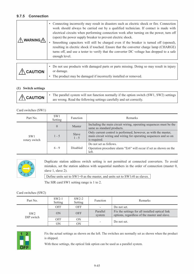
9-45
9.7.5 Connection
• Connecting incorrectly may result in disasters such as electric shock or fire. Connectionwork should always be carried out by a qualified technician. If contact is made with electrical circuits when performing connection work after turning on the power, turn off (open) the power supply breaker to prevent electric shock.
• Smoothing capacitors will still be charged even if the breaker is turned off (opened), resulting in electric shock if touched. Ensure that the converter charge lamp (CHARGE) turns off, and use a tester to verify that the converter DC voltage has dropped to a safe enough level.
• Do not use products with damaged parts or parts missing. Doing so may result in injury or damage.
• The product may be damaged if incorrectly installed or removed.
(1) Switch settings
• The parallel system will not function normally if the option switch (SW1, SW2) settings are wrong. Read the following settings carefully and set correctly.
Card switches (SW1)
Part No. SW1 Setting Function Remarks
SW1rotary switch
0 Master Including the main circuit wiring, operating sequences must be the same as standard products.
1 - 5 Slave1 - 5
Only current control is performed, however, as with the master, main circuit wiring and wiring for operating sequences and so on is required.
6 - 9 DisabledDo not set as follows.Operation procedure alarm "Er6" will occur if set as shown on the left.
05
987
64 3 2
1Duplicate station address switch setting is not permitted at connected converters. To avoidmistakes, set the station address with sequential numbers in the order of connection (master 0,slave 1, slave 2).
Define units set to SW1=0 as the master, and units set to as slaves.
The SIR card SW1 setting range is 1 to 2.
Card switches (SW2)
Part No. SW2-1Setting
SW2-2Setting Function Remarks
SW2DIP switch
OFF OFF - Do not set.
ON OFF Parallel system
Fix the settings for all installed optical link options, regardless of the master and slave.
OFF ON- Do not set.
ON ON
OFF
1 2 Fix the actual settings as shown on the left. The switches are normally set as shown when the product is shipped.
With these settings, the optical link option can be used as a parallel system.

9-46
(2) Optic fiber cable connection
• If the plastic optic fiber cable is bent for long periods of time with curvature of 35 mm orless, a converter link error (Erb) may occur, resulting in an alarm. If this happens, converter output will be cut. Always ensure that the optic fiber cable has a curvature of 35 mm or greater.
Connect the OPC-VG7-SI/SIR cards on each converter with the optic fiber cables provided.
Each of the plugs on the end of the optic fiber cables is a different color (blue, gray), and should be connected to the same corresponding color on each card. Connect the cables to create a complete loop. If, for example, connecting three units (1, 2, 3), use three
Option card optical connectors
Part No. Name Color OverviewT-1528 TX Gray Transmitter (optical communication - transmission)R-2528 RX Blue Receiver (optical communication - receipt)
R-2528 T-1528
OPC-VG7-SI/SIRSlave 1
R-2528 T-1528
05
987
64 3 2
1
05
987
64 3 2
1
OPC-VG7-SI/SIRSlave 2
SW1 SW1
R-2528 T-1528
05
987
64 3 2
1
Blue(receipt)
Gray(transmission)
OPC-VG7-SI/SIRMaster
SW1
3 unit example
Blue(receipt)
Blue(receipt) Blue
(receipt)
Blue(receipt)
Blue(receipt)
Gray(transmission)
Gray(transmission)
Gray(transmission)
Gray(transmission)
Gray(transmission)
Plastic fiber cable absolute maximum rating
Item Min. Max. Unit RemarksStorage temp. range -40 +75 C
Tension 50 N Within 30 minutes
Short-term bend radius 10 - mm Operation will cease within 1 hour, and a converter link error (Erb) will occur.
Long-term bend radius 35 - mm If bent with curvature of 35 mm or less for long periods, a converter link error (Erb) may occur. Ensure a curvature of 35 mm or greater.
Tensile strength(over long periods) - 1 N
Flexibility - 1000 times 90 bend on 10 mm mandrel (shaft, spindle)Impact - 0.5 kg Impact test based on MIL-1678, Mothod2030, Procefurel
Guaranteed minimum distance 20 m Minimum guaranteed value due to transmission loss (0 - 70 C)
Weight 4.6 g/m* A Mitsubishi Rayon plastic optic cable (accessory) is used.

9-47
(3) Parallel/single system switching
1) Function overview
Parallel system operation with high-speed serial card (OPC-VG7-SI/SIR) can be canceled and switched to single system operation for a single unit with external digital input signal [OPT-DI].
This switching function is used as an emergency backup in cases where a malfunction occurs at a converter in a parallel system, and operation is continued at reduced load capacity with a functional converter only.
The function code for parallel system switching is H12 "Parallel system".
The following diagram illustrates basic connection for parallel system and single system switching.
OPC-VG7-SI/SIR
X1 (E01=4)
CM
[OPT-DI]
RST[RST] RHC-D
Master[CM]
OPC-VG7-SI/SIR
(E01=4) X1
CM
RST RHC-DSlave
[OPT-DI]
[RST]
[CM]
Optical communication
DC common
2) Parallel/single system switching specifications
Parallel/single system switching is performed with function code H12 and digital input [OPT-DI]. If the X1 terminal is the normal open setting with function code H12 = 1 "parallel system", [OPT-DI] = ON (closed) will be the single system (parallel system canceled), and [OPT-DI] = OFF (open) will be the parallel system.
Table 9.7-1
Function CodeH12 "Parallel System" [OPT-DI] Drive System
0: DisabledOFF Single
ON Single
1: EnabledOFF Parallel
ON Single
<Precautions>
1. Switching input is disabled during operation, and is not updated until the converter stops.
2. This function is only valid when the system is equipped with a high-speed serial card, and the X1 terminal is assigned to [OPT-DI].
3. If using this switching function, it is only possible to run a single converter among those that make up the parallel system. Do not run multiple converters simultaneously with the single system.
4. If using the remaining two systems of a three converter system in parallel system operation when one of the converters has malfunctioned, it is first necessary to reconfigure the system as a two converter system by making changes to the optic fiber cable wiring, changing the station address switch settings on the option card, and resetting the function code.

9-48
(4) Parallel system alarm indication
If an alarm occurs at the master or slave unit when performing parallel system operation, all units switch to alarm mode simultaneously and stop. At the same time, an alarm code for the 1st alarm cause is displayed on the keypadLED display area of all units.
The unit at which the alarm occurred can be determined from the displayed alarm code. Even if multiple alarms occur simultaneously, it is only the 1st alarm cause that is displayed as the cause alarm for other stations. Furthermore, the alarm history displays normal alarm codes.
(5) Setting the number of connected units
It is necessary to set the number of slave units connected by optic fiber for the function code. This is not the setting for the number of units including the master.
Number of connected units and function codes
Item Function H13 Setting Remarks
Function code H13 Parallel systemNo. of slave stations
1 1 master + 1 slave = 2 unit system setting
2 1 master + 2 slave = 3 unit system setting
3 1 master + 3 slave = 4 unit system setting
4 1 master + 4 slave = 5 unit system setting
5 1 master + 5 slave = 6 unit system setting
The H13 setting range when equipped with SIR card is 1 to 2.
Setting example
When using a 2 unit systemSet to H13=1 for all units.
When using a 3 unit systemSet to H13=2 for all units.
If the H13 setting is incorrect, an alarm will occur, and the parallel system will cease to function normally.Ensure to set correctly.
When alarm occurs at other station(Alarm trip due to other station cause)
OH2.0=OH2
External alarmPRGRESET
When alarm occurs at local station
Dot display OH20=OH2
External alarmPRGRESET
(Alarm trip due to local station cause)
MasterH13=1
SlaveH13=1
MasterH13=2 H13=2 H13=2
Slave 1 Slave 1

9-49
9.7.6 Basic connection diagram
The following is a connection example (3 unit system) when performing parallel system operation.
Special instructions:
1. An alarm stoppage condition occurs simultane-ously at all units when an alarm occurs (30X operation), however, the RUN signal should beopened at all converters in the interests of safety.
2. After ensuring that all converter units are ready for operation [RDY], specify a sequence that issues a run command to the inverter (ensure that it is theinverter).
3. Alarms can be reset simultaneously at all units by inputting an [RST] signal from any unit. Ifswitched over to a single system, only the unit to which the [RST] signal is input is reset.
4. When using the parallel/single system switching function, [OPT-DI] is assigned to the X1 contact input.When switching to a single system, input an[OPT-DI] signal, bypass alarm circuits for other than single operation units, and create a sequence circuit so that a run command is input only to the single operation unit.
30X IRX
MASTER
RDY
30A
30 3030C
MASTER SLAVE 230A
30C Y5A
Y5C
Y5A
Y5C
RDY
SLAVE 2
Converteroperationcommand
CRX
30X
Inverteroperationcommand
30
SLAVE 130A
30C
Y5A
Y5C
RDY
SLAVE 1
MASTERbypass
SLAVE 1bypass
SLAVE 2bypass
MASTERbypass
SLAVE 1bypass
SLAVE 2bypass
Figure 9.7-1
OP
C-V
G7-
SI/S
IR RX TX
[X1]
[RUN]
[RST]
[30C]
[Y5A]
[30A][30B]
[Y5C]
Main power
High-speed communication (1 Mbps), optic fiber
[CM]
Control powerR0,T0
[RDY]
[30]
RHC D-TypeMASTER
SW
1=0
SW
2-1=
ON
SW
2-2=
OFF
L1/R,L2/S,L3/T
RHC D-TypeSLAVE 1
RHC D-TypeSLAVE 2
P,N
Power supply to inverter
R1,S1,T1
R2,T2
[73A][73C]
CRX
OPC
-VG
7-SI
/SIR RX TX
[X1]
[RUN]
[RST]
[30C]
[Y5A]
[30A][30B]
[Y5C]
Main power
[CM]
Control powerR0,T0
[RDY]
[30]
SW
1=1
SW
2-1=
ON
SW
2-2=
OFF
L1/R,L2/S,L3/T
P,N
R1,S1,T1
R2,T2
[73A][73C]
CRX
OPC
-VG
7-SI
/SIR RX TX
[X1]
[RUN]
[RST]
[30C]
[Y5A]
[30A][30B]
[Y5C]
Main power
[CM]
Control powerR0,T0
SW
1=2
SW
2-1=
ON
SW
2-2=
OFF
L1/R,L2/S,L3/T
P,N
R1,S1,T1
R2,T2
[73A][73C]
CRX[RDY]
[30]

9-50
9.7.7 Operation
(1) Settings prior to operation
• Certain function codes must be set to the same value for both master and slave units. Normal operation will not be possible without this setting.
Before starting operation, always ensure that the following function codes are the same for both the master and slave units. The function codes are set to the same values when the product is shipped, but should be checked again.
Applicable Code Function RemarksF03 Current rating switching These must be the same.E15 Overload warning level These must be the same.H12, H13 Dedicated parallel system codes These must be the same.
(2) Turning on the power
• Input a "RUN" operation command to both the master and slaves.The system will not start up if this command is given only to the master or slave.
• Certain slave unit function code settings are disabled at the keypad display.• After turning on the control power, it is not possible to start the initial operation for the
first 10 seconds while initial processing is being performed.If the power is turned on with a run command input, operation starts approximately 10 seconds later.
• If operation is started without the power turning on at even one of the units in a parallel system, a converter link error (Erb) occurs. This alarm does not occur if operation is not started.
There is no need to turn on the power for all units simultaneously. Furthermore, there is no particular order in which the power must be turned on. No alarms are detected unless operation is started, and therefore the power can be turned on in any order.
Run/stop commands
Run and stop commands are input to both master and slave units. It is necessary to understand that multiple slave units that are optically linked are simply hardware used to perform current control.
I/O function
The master unit has no restrictions, however, slave units have the following functional restrictions.
Valid slave I/O functionsValid Functions for
Parallel System Slaves(Items not listed are invalid)
Terminal Signal Remarks
Digital input
Run/stop command [RUN]Error reset [RST] Resets all system units.External alarm [THR]73 answer back signal [73ANS]Option DI [OPT-DI] Performs parallel/single system switching.
Digital output
Batch alarm [30A, 30B, 30C]
Running [RUN]
Functions with"Operating information from master","Terminal block/communication RUN"AND information.
Ready [RDY]Lifetime warning [LIFE] Unit's own lifetimeCooling fan overheat warning [PRE-OH]

9-51
Valid Functions for Parallel System Slaves
(Items not listed are invalid)Terminal Signal Remarks
Digital output
Overload warning [PRE-OL]Driving [DRV]Regenerating [REG]Synchronizing power supply frequency [SY-HZ]
Alarm details [AL1 - 3] Outputs with alarm information from master added.
Option DO [OPT-DO]Analog input All invalid -
Analog output
Input power [PWR] Outputs input power calculated by unit itself.Input current effective value [I-AC] Outputs voltage and current detected by unit
itself.Input voltage effective value [V-AC]
Intermediate DC voltage [V-DC] Outputs intermediate voltage detected by unit itself.
Power supply frequency [FREQ] Outputs frequency detected by unit itself.+10, -10 V test [P10, N10]
(3) Keypad functions
The keypad functions can be used without restrictions for either the master or slave.
(4) Function codes (F - U)
The master unit can be used without restrictions, however, slave units have functional restrictions. Code "1" must be set to the same value for both the master and slave.
Slave function codes
Code Class Code Class Code Class Code Class Code Class Code Class Code ClassF00 2 E01 2 E10 2 E19 2 H01 2 H10 2 H19 0F01 0 E02 2 E11 2 E20 2 H02 2 H11 2 H20 0F02 0 E03 2 E12 2 E21 2 H03 2 H12 3F03 1 E04 2 E13 2 E22 2 H04 2 H13 3F04 2 E05 2 E14 2 E23 2 H05 2 H14 2F05 2 E06 2 E15 1 E24 2 H06 2 H15 0F06 2 E07 2 E16 2 E25 2 H07 2 H16 0F07 2 E08 2 E17 2 E26 2 H08 2 H17 0F08 0 E09 2 E18 2 E27 2 H09 2 H18 0
(5) Function codes (S: Command data, M: Monitor)
S codes (command data)
The master unit can use all codes, however, only S01 "Operation" is valid for slave units.However, section "9.7.7 I/O Function" restrictions apply.
M codes (monitor data)
Both master and slave units can be used without restrictions.
0: Setting invalid1: Setting valid (code for which same value as master must be
set)2: Setting valid (code for which no need to set same value as
master)3: Setting valid (code for which setting unique to parallel system
required)

9-52
9.7.8Protection functions
• When an alarm occurs for some reason at even a single converter unit of a parallel system comprising two or more units, there will be insufficient capacity even when continuing operation with the remaining unit(s), resulting in cases where the machine system is unable to function normally. To eliminate such cases, an instantaneous (within several ms) alarm occurs at all units in the parallel system connected by optical link option. Furthermore, it is also necessary for the customer to create sequences that stop all units using 30X (batch alarm output).
• After the converter protection function has activated and the cause of the alarm has been eliminated, converters are restarted by resetting the alarms with the run command ON. There is a risk of injury, and therefore alarms should be reset only after ensuring that the run command is OFF (open).
• If the optic fiber cable connecting units is cut or damaged during converter operation, normal operation will no longer possible, and so an alarm (converter link error: Erb) status is forcibly triggered at the converter side. This alarm does not occur while converters are stopped.
(1) Converter link error (Erb)
If the optic fiber cable is cut or damaged, or comes away from the connector during converter operation, a converter link error (Erb) occurs, resulting in an alarm at all units. If converter alarm output is based on inverter external alarm conditions, an alarm trip condition also occurs at the inverter, resulting in a free-run stop.
The alarm status cannot be cleared even by inputting a reset command (via keypad, terminal block or communication system) if the cause of the alarm has not been eliminated. Always reset the alarm status after investigating the cause of the alarm.
"Erb" troubleshooting
The following causes are likely when an Erb alarm occurs.
(1) The optic fiber cable is not connected, or the connector has not been fully inserted.
(2) The optic fiber cable is twisted with a curvature of less than 35 mm, or the cable is bent.
(3) The optic fiber cable connection plug does not match the color (blue, gray) of the PCB connector.
(4) The optic fiber cable connection does not form a loop. Always ensure that signals from the master are looped back.
(5) Strong light (e.g., flashlight) is applied to the optical fiber.
(2) Operation procedure error (Er6)
An alarm occurs when the hardware switches are incorrectly set as follows.
• When optical link option hardware station address SW1 is set to 6 or higher.• When the optical link option hardware station address SW1 setting is greater than H13 "No. of parallel system
slave stations".
When equipped with two optical link options.

9-53
(3) Batch alarm processing
If an alarm occurs at the master (slave) unit, the same alarm is displayed at all stations by optical transmission, a 30X operation is performed, and the converters are cut off.
(4) Reset processing
All stations are batch reset provided that the alarm cause is cleared with a master (slave) reset command.
Reset conditions
Master Alarm Status Slave Alarm Status Applicable toReset command from master Valid Valid All unitsReset command from slave Valid Valid All units

9-54
9.8 SIR Option9.8.1 Product overview
Large-capacity converter drive
RHC-D Series PWM converter transformer-less parallel systems drive converters by connecting to multiple units (2 multiplex, 3 multiplex) without transformer at the primary side in contrast to standard parallel systems that require primary side power supply insulation with a transformer. This option applies to load sharing for all converters, and facilitates drive with up to a 3 multiplex system.
Current sharing
To drive an inverter with multiple converters, it is necessary to equip each converter with an optical link option. With this optical link, current commands allotted to converters are conveyed instantly. Current is controlled (feedback control) for each converter, enabling operation with load sharing determined by the drive capabilities of each converter.
Parallel/single system switching function
In cases such as where a single converter malfunctions when performing parallel system drive, parallel system operation can be canceled and switched to standard single system operation with the parallel/single system switching function.
[Installation restrictions]
It is not possible to equip converters with two SIR options at the same time. By doing so, operation procedure error "Er6" will occur.
9.8.2 Model
Model: OPC-VG7-SIR
Opt
Accessories: Spacer x 3Screw (M3) x 3Optic fiber cable x 1 (for transmission/receipt)

9-55
9.8.3 Specifications
Control specifications
Item SpecificationsApplicable converter capacity
MD (CT) spec. (up to 2,400kW: 3 multiplex), LD (VT) spec. (up to 3,000kW: 3 multiplex)
Parallel control method AVR constant control with DC ACR minorOutput voltage Fixed 710 VDCCarrier frequency 2.5kHzInput power 380 - 440 V, 50Hz/60Hz * The capacity must be reduced if less than 400 V.Input power factor Approx. 0.94 (30% load or higher)
Input harmonic current The METI harmonic suppression countermeasure guidelines state that the scale factor Ki can be 0.
Restart following momentary power interruption
Output is cut following a momentary power interruption, and the converter is restarted when power is restored.
Control function Slave units have partial functional restrictions.
Ded
icat
edfu
nctio
ns
Hardwaresettings
Parallel system settings
Sets optional applications.The parallel system setting is (SW2-1=ON, SW2-2=OFF).
Station address setting
Optional hardware switch SW1SW1=0: master
"1", and slave 2 is set to "2".
Codesettings
Parallelsystem
Parallel/single system switching is performed with function code H12 "Parallel system".0: Parallel system disabled (factory default)1: Parallel system enabledWhen set to function code H12 = "Parallel system enabled", dynamic parallel/single system switching is possible with digital input signal [OPT-DI].
Slaveqty setting
The number of optically linked slave units is set with function code H13 "No. of parallel system slave stations". With a two unit parallel system, for example, the number of slaves will be "1".
Main circuit non-insulation system parallel system specifications
The optical link option is applied to multipleconverters, control is synchronized across each converter, and load current sharing is controlled.
If using a common connection for DC circuits at the converter output side, there is no need for an isolation transformer at the main power supply side, enabling transformer-less connection of the primary side of each converter.
One of the features of parallel systems is that they are compatible with large-capacity loads greater than thesingle unit capacity.
Note: Input filters used for transformer-less parallel connections with RHC132S-4D to RHC315S-4Dshould be configured with a filter stack. It is not possible to configure filter circuits with peripheral equipment.
Master(RHC-4DE)
Slave 1(RHC-4DE)
Slave 2(RHC-4DE)
P,N P,N P,N
Inverter power supply
OPC-VG7-SIR
R,S,T R,S,T
OPC-VG7-SIR
R,S,T
OPC-VG7-SIR
RHF RHF RHF
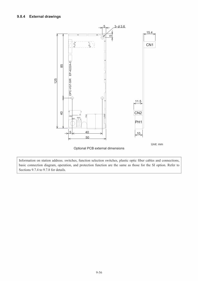
9-56
9.8.4 External drawings
5 3- 3.6
5BA
54
32
1P
H1
PH
2
15
CN2SW1 SW2
21
1415
1617 29
30
21
-E
P-4
222A
-CO
PC
-VG
7-S
IR
15.4
CN1
11.5
CN2
PH1
1040550
85
125
40
Unit: mmOptional PCB external dimensions
Information on station address. switches, function selection switches, plastic optic fiber cables and connections, basic connection diagram, operation, and protection function are the same as those for the SI option. Refer to Sections 9.7.4 to 9.7.8 for details.

10-1
10 Specifications10.1 Standard SpecificationsMD (CT)-mode converters for medium loadThree-phase 400 V class series (Stack type)
Item Specifications
Converter typeRHC S-4DE RHC B-4DE *1
132 160 200 220 280 315 630 710 800Applicable inverter capacity(kW) 132 160 200 220 280 315 630 710 800
Out
put
ratin
gs
Continuous capacity(kW) 150 182 227 247 314 353 705 795 896
Overload rating 150% of the continuous rating for 1 minuteOutput voltage 640 to 710 VDC (Varies depending upon the input voltage) *2
Required power supply capacity (kVA) 161 196 244 267 341 383 762 858 967
Carrier frequency (kHz) 5 *3
Inpu
tpow
er Number of phases, voltage and frequency Three-phase, 3-wire, 380-440 V/50 Hz, 380-460 V/60 Hz *4
Allowable voltage/frequency fluctuation
Voltage: -15 to +10%, Frequency: +5 to -5%Interphase voltage unbalance: 2% or less *5
Approx. mass (kg) *1 95 95 95 125 135 135 135 x 3 135 x 3 135 x 3Enclosure IP00, UL open type
Note: The above specifications apply when Function code F03 = 0 (MD (CT)).*1 A single RHC B-4DE unit consists of three stacks.*2 The output voltage is approximately 640 VDC for 400 V source voltage, 686 VDC for 440 V, and 710 VDC for 460 V.*3 2.5 kHz when the OPC-VG7-SIR is mounted (in transformerless connection).*4 For 380-398 V/50 Hz and 380-430 V/60 Hz, tap switching is required inside the converter.
For less than 400 V, capacity should be derated.
*5 67×(V) voltageaveragephase-Three(V) voltageMin.-(V) voltageMax.=(%)unbalanceVoltage
LD (VT)-mode converters for light loadThree-phase 400 V class series (Stack type)
Item Specifications
Converter typeRHC S-4DE RHC B-4DE *1
132 160 200 280 315 630 710 800Applicable inverter capacity(kW) 160 200 220 315 355 710 800 1000
Out
put
ratin
gs
Continuous capacity(kW) 182 227 247 353 400 795 896 1120
Overload rating 110% of the continuous rating for 1 minuteOutput voltage 640 to 710 VDC (Varies depending upon the input voltage)*2
Required power supply capacity (kVA) 196 244 267 383 433 858 967 1210
Carrier frequency (kHz) 5 *3
Inpu
t pow
er Number of phases, voltage and frequency Three-phase, 3-wire, 380-440 V/50 Hz, 380-460 V/60 Hz *4
Allowable voltage/frequency fluctuation
Voltage: -15 to +10%, Frequency: +5 to -5%Interphase voltage unbalance: 2% or less *5
Approx. mass (kg) *1 95 95 95 135 135 135 x 3 135 x 3 135 x 3Enclosure IP00, UL open type
Note: The above specifications apply when Function code F03 = 1 (LD (VT)).*1 A single RHC B-4DE unit consists of three stacks.*2 The output voltage is approximately 640 VDC for 400 V source voltage, 686 VDC for 440 V, and 710 VDC for 460 V.*3 2.5 kHz when the OPC-VG7-SIR is mounted (in transformerless connection).*4 For 380-398 V/50 Hz and 380-430 V/60 Hz, tap switching is required inside the converter.
For less than 400 V, capacity should be derated.
*5 67×(V) voltageaveragephase-Three(V) voltageMin.-(V) voltageMax.=(%)unbalanceVoltage

10-2
10.2 Common SpecificationsTable 10.2-1 Common Specifications
Item Specifications
Con
trol
Control method AVR control with DC ACR minor
Running/Stopping
Starts rectification when the converter is powered ON after connection. Starts boosting when it receives a Run signal (terminals [RUN] and [CM] short-circuited or a run command via the communications link). After that, the converter is ready to run.
Running status signal Running, power running, regenerative operation, ready-to-run, alarm output (for any alarm), etc.
MD/LD switching
Selection between:MD (CT): 150% of overload rating for 1 min.andLD (VT): 110% of overload rating for 1 min.
Carrier frequency Fixed at 5 kHz (2.5 kHz when the OPC-VG7-SIR is mounted)
Input power factor 0.99 or above (at full load) (except when the OPC-VG7-SIR is mounted) *1
Input harmonics current Conversion coefficient ki can be "0" according to the Japanese Guideline for Suppressing Harmonics by the Ministry of Economy, Trade and Industry.
Restart after momentary power failure
Shields the gate when the voltage level drops to the undervoltage level if a momentary power failure occurs. And restarts the converter automatically when the power is restored.
Power limiting control Controls the power not to exceed the preset limit.
Indi
catio
n
Alarm indication(Protective function)
AC fuse blown, AC overvoltage, AC undervoltage, AC overcurrent, AC input current error, input phase loss, power line frequency synchronization error, DC fuse blown, DC overvoltage, DC undervoltage, charging circuit error, heat sink overheat, external alarm, converter overheat, overload, memory error, keypad communications error, CPU error, network device error, operation procedure error, A/D converter error, optical network error
Alarm historySaves and displays the most recent 10 alarm records.Saves and displays the detailed information of the trip cause for the previous alarm.
Monitor Displays input power, input current in (RMS), input voltage (RMS), DC link bus voltage and power source frequency.
Load factor Allows the user to measure the load factor with the keypad.
Display language Function codes can be entered or referred to in any of the three languages--Japanese, English and Chinese.
Charge lamp Lights when the power is supplied to the converter. It also lights only when the control power is being charged.
Com
mun
icat
ion
General specificationsMonitoring (polling) the running information, running status and function code data, and controlling (selecting) the terminals [RUN], [RST] and [X1].Note: Function codes except S codes cannot be written.
Stru
ctur
e sp
ecifi
catio
n Enclosure IP00
Cooling system Forced cooling
Paint color Munsell 6PB3/3, semi-gloss
*1 The input power factor is reduced to approximately 0.95 during regenerative operation when the power supply voltage is 420 V and the operating load is 50% or above.

10-3
Item Name SpecificationIn
put s
igna
ls
Run/Stop command [RUN] Short-circuiting terminals [RUN] and [CM] starts boosting; opening them stops it.
Alarm reset command [RST]When the converter stops due to an alarm, removing the alarm factor and short-circuiting the terminals [RST] and [CM] cancels the protective function, restarting the converter.
General-purposetransistor input [X1]
0: Enable external alarm trip THR 1: Cancel current limiter LMT-CCL2: 73 answerback 73ANS 3: Switch current limiter I-LIM4: Option D I OPT-DI
Digital input common [CM] Common terminal for digital input signals
Out
put s
igna
ls
Alarm output[30A][30B][30C]
Outputs a signal when the converter protective function is activated so that the converter stops due to an alarm.(Contact: 1C, Upon alarm, 30A-30C: ON)(Contact capacity: 250 VAC, 0.3A, cos =0.3 )A "b" contact (normal close) can be set with Function code E14. Upon alarm, 30A-30C OFF.
General-purposetransistor output (Standard 3 points, extended 8 points)
[Y1][Y2][Y3]
0: Converter running RUN, 1: Converter ready to run RDY,2: Power supply current limiting IL, 3: Lifetime alarm LIFE,4: Heat sink overheat early warning PRE-OH,5: Overload early warning PRE-OL, 6: Power running DRV,7: Regenerating REG, 8: Current limiting early warning CUR,9: Restarting after momentary power failure U-RES,10: In synchronization with source frequency SY-HZ,11: Alarm content 1 AL1, 12: Alarm content 2 AL2,13: Alarm content 4 AL4, 14: Option DO OPT-DO* Mounting the OPC-VG7-DIOA option makes 8 points of DO extended
functions available. (DI functions are not available.)
[Y11]to
[Y18]
Digital output common [CME]
Relay output (Standard 1 point)
[Y5A][Y5C]
General-purpose analog output (Standard 1 point, extended 2 points)
[AO1] 0: Input power PWR, 1: Input current in RMS I-AC,2: Input voltage in RMS V-AC, 3: DC link bus voltage V-DC,4: Power supply frequency FREQ, 5: +10V test P10, 6: -10V test N10* Mounting the OPC-VG7-AIO option makes 2 points of AO extended
functions available. (AI functions are not available.)
[AO4][AO5]
Analog output common [M] Common terminal for analog output signals
Charging circuit control output
[73A][73C]
Control output for external charging circuit(Contact capacity: 250 VAC 5A max.)
Com
mun
icat
ion
spec
ifica
tions
General communication specifications
Monitoring (polling) the running information, running status and function code data, and controlling (selecting) the terminals [RUN], [RST] and [X1].Note: Function codes except S codes cannot be written.
T-Link (Option) Mounting the OPC-VG7-TL option enables communication with a T-Link module of MICREX-F or MICREX-SX via a T-Link network.
SX Bus (Option) Mounting the OPC-VG7-SX option enables communication with a MICREX-SX via an SX bus network.
CC-Link (Option) Mounting the OPC-VG7-CCL option enables communication with a CC-Link master.

10-4
10.3 External DimensionsConverter stackRHC132S-4DE, RHC160S-4DE, RHC200S-4DE

10-5
Converter stackRHC220S-4DE, RHC280S-4DE, RHC315S-4DE

10-6
V-phase stack of RHC630B-4DE, RHC710B-4DE, RHC800B-4DE(The S-phase stack should be used in combination with the R- and T-phase stacks shown on the next page.)

10-7
Converter stack (U-/W-phase stack)U-/W-phase stack of RHC630B-4DE, RHC710B-4DE, RHC800B-4DE(The R- and T-phase stacks should be used in combination with the S-phase stack shown on the previous page.)

10-8
10.4 Peripheral Devices(1) Boosting reactor
Boosting reactor model
Rated current
(A)
Inductance (mH)
Rated capacity (kVA)
Dimensions (mm) Weight (kg) Figure
Heat-resistant
classW WP D DP DT H K M
LR4-630C 1200 0.068 110.3 600 200 440 390 285 640 19 - 450 A HLR4-710C 1350 0.060 104.5 645 215 440 390 295 730 19 - 510 B HLR4-800C 1520 0.053 118.2 690 230 450 400 290 850 19 - 600 B H
(2) Filtering reactor
Filtering reactor model
Rated current
(A)
Inductance (mH)
Rated capacity (kVA)
Dimensions (mm) Weight(kg) Figure
Heat-resistant
classW WP D DP DT H K M CW CH
LFC4-630C 1200 0.016 25.9 435 145 295 255 200 550 15 - 75 17.5 175 A HLFC4-710C 1350 0.014 24.5 480 160 295 255 215 570 15 - 100 30 190 A HLFC4-800C 1520 0.013 27.7 480 160 320 270 220 600 15 - 100 30 220 A H
<Figure A> <Figure B>
LR4-710C CuP t8 100LR4-800C CuP t10 100
MA
X.H
MAX.W
MAX.DT
D
DP4 KWP
MA
X.H
MAX.W
MAX.DT
D
DP
4 K
WP
Nameplate Nameplate
Detail of terminal Detail of terminal
<Figure A> MAX.DT
DPWP
MA
X.H
CW
CH
LFC4-630C CuP t10 75LFC4-710C CuP t8 100LFC4-800C CuP t10 100
MAX.W D4
Mounting holes
Nameplate
Detail of terminal

10-9
(3) Filtering capacitor
Filtering capacitor model
Dimensions (mm)Figure Weight
(kg)A B C D E F G H ICF4-630C 435 400 - 100 80 15 x 20 elongate hole 460 275 M12 A 20.0CF4-710C 435 400 - 100 80 15 x 20 elongate hole 520 335 M12 A 23.0CF4-800C 435 400 - 100 80 15 x 20 elongate hole 610 425 M12 A 27.0
Note 1: There are restrictions on the mounting direction of the capacitors. Observe the mounting direction shown above.Note 2: Each of the CF4-630C to CF4-800C consists of two capacitors. The table above shows values for a single
capacitor.
(4) Filtering resistor
<Figure A>
Filtering resistor modelequipped with cover Figure Weight (kg) Q'ty
400 V seriesRF4-630C
A70
1RF4-710CRF4-800C 80
Note: A resistor is a heating element, so mount it at a place where it does not thermally affect other devices.
< Figure A >
mounting hole
- F
mounting hole

10-10
(5) AC fuse
(6) Charging resistor
Charging resistor model
Dimensions (mm)Weight
(kg)G H J L M Z D K t A C l
GRZG400 1 40 40 9.5 385 411 10 47 39 2.4 10 5.5 330 0.85
32
58
86
90.25
160.5
150
6
4x 15
74190
150
74.5
20
< Figure B> HF5G2655< Figure A> SA598473

10-11
10.5 Generating Loss(1) Generating loss in the MD (CT) mode
StacksConverter stack Filter stack
Model Generating loss (W) Model Generating loss
(W)RHC132S-4DE 2000 RHF160S-4DE 2850RHC160S-4DE 2950 RHF160S-4DE 2850RHC200S-4DE 3650 RHF220S-4DE 3650RHC220S-4DE 4150 RHF220S-4DE 3650RHC280S-4DE 5100 RHF280S-4DE 4600RHC315S-4DE 5750 RHF355S-4DE 5200RHC630B-4DE 11800 - -RHC710B-4DE 13200 - -RHC800B-4DE 14800 - -
Peripheral devices
Applicable converter model
Boosting reactor Filtering reactor Filtering resistor
Model Generating loss (W) Model Generating
loss (W) Model Generating loss (W)
RHC630B-4DE LR4-630C 2300 LFC4-630C 510 RF4-630C 4722RHC710B-4DE LR4-710C 2600 LFC4-710C 630 RF4-710C 5361RHC800B-4DE LR4-800C 2900 LFC4-800C 620 RF4-800C 6024
(2) Generating loss in the LD (VT) mode
StacksConverter stack Filter stack
Model Generating loss (W)) Model Generating loss
(W)RHC132S-4DE 2400 RHF160S-4D 2850RHC160S-4DE 3600 RHF220S-4D 3650RHC200S-4DE 3950 RHF220S-4D 3650RHC280S-4DE 5700 RHF355S-4D 5200RHC315S-4DE 6400 RHF355S-4D 5200RHC630B-4DE 13200 - -RHC710B-4DE 14650 - -RHC800B-4DE 18100 - -
Peripheral devices
Applicable converter model
Boosting reactor Filtering reactor Filtering resistor
Model Generating loss (W) Model Generating
loss (W) Model Generating loss (W)
RHC630B-4DE LR4-710C 2600 LFC4-710C 630 RF4-710C 5361RHC710B-4DE LR4-800C 2900 LFC4-800C 620 RF4-800C 6024RHC800B-4DE LR4-1000C 4500 LFC4-1000C 1080 RF4-1000C 7728

11-1
11 Function Code Tables11.1 Function Code Configuration
Table 11.1-1 Function Code Groups and Function Codes on Keypad
Function code group Function codes Remarks
Fundamental functions F codes F00 to F08 These function codes are alwaysdisplayed on the keypad.Extension terminal functions E codes E01 to E27
High performance functions H codes H01 to H20
Serial communication functions S codes S01 to S03 These function codes cannot be changed from the keypad.Monitoring functions M codes M09 to M52
User application functions U codes U01 to U10
11.2 Function Code TablesTable 11.2-1 provides descriptions about the column headers in function code tables.
Table 11.2-1 Column Headers in Function Code Tables
Column headers Description
Function code Function code group and code number
Communications address
Link No. Address to be used to refer to or change function code data via T-Link, SX bus or CC-Link. Function codes with no address specification are inaccessible.Data change is allowed only for S codes.
Function code name Name assigned to a function code
Data setting range Allowable data setting range and definition of each data.
Format Indicates a format type to be used to refer to or change function code data via T-Link, SX bus or CC-Link.
Code numberFunction code group

11-2
Table 11.2-2 Fundamental Functions (F codes)
Functioncode
Communicationsaddress Function code name Data setting range Format
485 No Link No.F00 0h 46h Data protection 0 or 1
0: Enable data change1: Protect dataThis write-protects data from the keypad.Use "STOP + / V" keys to change data.
40
F01 1h 47h Harmonics suppressing filter
0 or 10: With filter1: Without filter
41
F02 2h 48h Restart mode after momentary power failure (Selection)
0 or 10: Disable1: Enable
42
F03 3h 49h Current rating switching 0 or 10: MD (CT) mode (Overload current 150%)1: LD (VT) mode (Overload current 110%)
43
F04 4h 4Ah LED monitor (Display selection)
0 to 50: Input power 1 (%)1: Input power 2 (kW)2: Input current (rms) (A)3: Input voltage (rms) (V)4: DC link bus voltage (V)5: Source frequency (Hz)
44
F05 5h 4Bh LCD monitor(Display selection)
0 to 2Switches the Run mode screen on the keypad.0: Operation guide screen1: Bar graph of running data 1 (Input power and
input current (rms))2: Bar graph of running data 2 (Source voltage
fluctuation and source frequency fluctuation)
45
F06 6h 4Ch LCD monitor (Language selection)
0 to 20: Japanese1: English2: Chinese
46
F07 7h 4Dh LCD monitor (Contrast adjustment)
0 to 100 (Low) to 10 (High)
0
F08 8h 85h Carrier frequency Fixed at 5 kHz even any setting is made.(2.5 kHz when the OPC-VG7-SIR is mounted)
59

11-3
Table 11.2-3 Extension Terminal Functions (E codes)
Function code
Communications address Function code name Data setting range Format
485 No Link No.E01 101h 4Eh Terminal [X1] function 0 to 4
0: External alarm THR1: Cancel current limiter LMT-CCL2: 73 answerback 73ANS3: Switch current limit I-LIM4: Option DI OPT-DI
47
E02 102h 4Fh Terminal [Y1] function 0 to 140: Converter running RUN1: Converter ready to run RDY2: Power supply current being limited IL3: Lifetime alarm LIFE4: Heat sink overheat early warning PRE-OH5: Overload early warning PRE-OL6: Power running DRV7: Regenerating REG8: Current limiting early warning CUR9: Restarting after momentary power failure
U-RES10: In synchronization with source frequency
SY-HZ11: Alarm content 1 AL112: Alarm content 2 AL213: Alarm content 3 AL414: Option DO OPT-DO
48
E03 103h 50h Terminal [Y2] function Refer to Terminal [Y1] function. 48E04 104h 51h Terminal [Y3] function Refer to Terminal [Y1] function. 48E05 105h 52h Terminal [Y5] function Refer to Terminal [Y1] function. 48E06 106h 53h Terminal [Y11] function
(DIO option)Refer to Terminal [Y1] function. 48
E07 107h 54h Terminal [Y12] function(DIO option)
Refer to Terminal [Y1] function. 48
E08 108h 55h Terminal [Y13] function(DIO option)
Refer to Terminal [Y1] function. 48
E09 109h 56h Terminal [Y14] function(DIO option)
Refer to Terminal [Y1] function. 48
E10 10Ah 57h Terminal [Y15] function(DIO option)
Refer to Terminal [Y1] function. 48
E11 10Bh 58h Terminal [Y16] function(DIO option)
Refer to Terminal [Y1] function. 48
E12 10Ch 59h Terminal [Y17] function(DIO option)
Refer to Terminal [Y1] function. 48
E13 10Dh 5Ah Terminal [Y18] function(DIO option)
Refer to Terminal [Y1] function. 48
E14 10Eh 5Bh I/O function (Normal open/close)
0000 to 007FDefines the normal state of RUN, X1, Y1 to Y3, Y5, and 30RY.0: Normal open1: Normal close
35
E15 10Fh 5Ch RHC overload early warning
50 to 105% 0

11-4
Function code
Communications address Function code name Data setting range Format
485 No Link No.E16 110h 5Dh Cooling fan ON/OFF
control0 or 10: Disable1: EnableThis control detects the temperature of the heat sinkin the converter and turns the cooling fan on or off automatically. If "Disable" is selected, the cooling fan keeps running.
42
E17 111h 5Eh Current limiting signal(Hysteresis width)
0 to 30% 0
E18 112h 5Fh AO1 function selection 0 to 100: Input power PWR1: Input current (rms) I-AC2: Input voltage (rm) V-AC3: DC link bus voltage V-DC4: Source frequency FREQ5: +10V output test P106: -10V output test N10
50
E19 113h 60h AO4 function selection(AIO option)
Refer to AO1 function selection. 50
E20 114h 61h AO5 function selection(AIO option)
Refer to AO1 function selection. 50
E21 115h 62h AO1 gain setting -100.00 to 100.00 (times) 7E22 116h 63h AO4 gain setting
(AIO option)-100.00 to 100.00 (times) 7
E23 117h 64h AO5 gain setting(AIO option)
-100.00 to 100.00 (times) 7
E24 118h 65h AO1 bias setting -100.0 to 100.0% 6E25 119h 66h AO4 bias setting
(AIO option)-100.0 to 100.0% 6
E26 11Ah 67h AO5 bias setting(AIO option)
-100.0 to 100.0% 6
E27 11Bh 68h AO1-5 filter setting 0.000 to 0.500 s 4

11-5
Table 11.2-4 High Performance Functions (H codes)
Function code
Communications address Function code name Data setting range Format
485 No Link No.H01 401h 69h Station address for
RS-485 communication0 to 255Enter the station address of RS-485.
0
H02 402h 70h Error processing(Common to communications options and RS-485)
0 to 30: Stop forcibly (Er4)1: Stop (Er4) after running for the period specified
by timer H03.2: Stop (Er4) if a communications error persists
exceeding the period specified by timer H33.3: Continue to run
57
H03 403h 71h Timer 0.01 to 20.00 s 3H04 404h 6Ah Baud rate 0 to 4
0: 38400 bps1: 19200 bps2: 9600 bps3: 4800 bps4: 2400 bps
51
H05 405h 6Bh Data length 0 or 10: 8 bits1: 7 bits
52
H06 406h 6Ch Parity check 0 to 20: None1: Even parity2: Odd parity
53
H07 407h 6Dh Stop bits 0 or 10: 2 bits1: 1 bit
54
H08 408h Communications line break time
0.0 to 60.0 s0.0: Disable detection0.1 to 60.0: Enable detectionIf no access to stations (including own station) is detected for the period specified by H08 during operation due to any error (e.g., line break), the converter causes an alarm Er4.
2
H09 409h 6Eh Response interval 0.00 to 1.00 sEnter the time until the converter issues a reply in response to a request from the host.
3
H10 40Ah 6Fh Protocol selection 0 to 30: Fuji's general-purpose inverter protocol1: SX protocol (Loader protocol)(for in-house use)2: Modbus RTU protocol3: Trace protocol (OPC-RHC-TR)
55
H11 40Bh - TL communication format(OPC-VG7-TL option)
0 or 10 : 4W + 4W1 : 8W + 8W
56
H12 40Ch 72h Parallel system(OPC-VG7-SI/SIR option)
0 or 10: Disable1: Enable
42
H13 40Dh 73h Number of slave stations in parallel system(OPC-VG7-SI/SIR option)
1 to 5Enter the number of slaves (without master) whenthe parallel system is enabled.
0
H14 40Eh 74h Alarm data deletion 0 or 1Setting H14 to "1" deletes all alarm data held in the memory. After that, the H14 data automatically reverts to "0."
11

11-6
Function code
Communications address Function code name Data setting range Format
485 No Link No.H15 40Fh 75h Current limiter value
(Driving 1)0 to 150% 16
H16 410h 76h Current limiter value(Driving 2)
0 to 150% 16
H17 411h 77h Current limiter value(Braking 1)
-150 to 0% 16
H18 412h 78h Current limiter value (Braking 2)
-150 to 0% 16
H19 413h 79h Current limiter early warning (Level)
-150 to 150% 16
H20 414h 7Ah Current limiter early warning (Timer)
0 to 60 s 0
Table 11.2-5 User Application Functions (U codes)
Function code
Communications address Function code name Data setting range Format
485 No Link No.U01 B01h 7Bh Reserved. -32768 to 32767 5
U02 B02h 7Ch SX bus station number monitor -32768 to 32767 5
U03 B03h 7Dh Reserved. 0000 to FFFF 9U04 B04h 7Eh AVR control response -32768 to 32767 5U05 B05h 7Fh DC voltage selection -32768 to 32767 5U06 B06h 80h Reserved. -32768 to 32767 5U07 B07h 81h Reserved. -32768 to 32767 5U08 B08h 82h Reserved. -32768 to 32767 5U09 B09h 83h Reserved. -32768 to 32767 5U10 B10h 84h Reserved. -32768 to 32767 5

11-7
11.3 List of Communication-dedicated Function CodesS codes
Table 11.3-1 Serial Communication Functions (S codes)
Function code
Communications address Function code name Data setting range Format
485 No Link No.S01 701h 1h Operation 0000 to FFFF 32S02 702h 2h Power supply current limit (Driving) 0.01% / 1d 7S03 703h 3h Power supply current limit (Braking) 0.01% / 1d 7
Although the writing of S02 and S03 is always possible, as for reflection of write-in data, a converter is performed at the time of a stop.M codes
Table 11.3-2 Monitoring Functions (M codes)
Function code
Communications address Function code name Data setting range Format
485 No Link No.M01 to
M08- - Reserved. - -
M09 809h 17h Source frequency 0.1 Hz / 1d 2M10 80Ah 18h Input power 0.1 kW / 1d 2M11 80Bh 19h Input current (rms) 0.1 A / 1d 2M12 80Ch 1Ah Input voltage (rms) 0.1 V / 1d 2M13 80Dh 1Bh Run command 0000 to FFFF 32M14 80Eh 1Ch Running status 0000 to FFFF 21M15 80Fh 1Dh Output terminals Y1 to Y18 0000 to FFFF 33M16 810h 1Eh Alarm content, latest alarm 0000 to FFFF 14M17 811h 1Fh Alarm content, previous alarm 0000 to FFFF 15M18 812h 20h Alarm content, alarm before previous
one0000 to FFFF 15
M19 813h 21h Alarm content, alarm before two previous ones
0000 to FFFF 15
M20 814h 22h Cumulative run time 10h / 1d 0M21 815h 23h DC link bus voltage 1V / 1d 0M22 816h 24h DC link bus voltage (P.U.) 0 to 65535 V 0M23 817h 25h Model code 0000 to FFFF 29M24 818h 26h Capacity code 0 to 29 28M25 819h 27h Converter ROM (main control) version 0000 to FFFF 9M26 81Ah 28h Transmission error code 0 to 65535 34
M27 to M34
- - Reserved. - -
M35 823h 31h Source frequency at alarm 0.1Hz / 1d 2M36 824h 32h Input power at alarm 0.1kW / 1d 2M37 825h 33h Input current (rms) at alarm 0.1A / 1d 2M38 826h 34h Input voltage (rms) at alarm 0.1V / 1d 2M39 - - Reserved. - -M40 828h 36h Running status at alarm 0000 to FFFF 21M41 829h 37h Output terminal at alarm 0000 to FFFF 33M42 82Ah 38h Cumulative run time at alarm 10h / 1d 0M43 82Bh 39h DC link voltage at alarm 1 V / 1d 0M44 82Ch 3Ah Converter internal temperature at alarm 1 C / 1d 5M45 82Dh 3Bh Heat sink temperature at alarm 1 C / 1d 5M46 - - - - -M47 82Fh 3Dh Service life of capacitor on printed
circuit board10h / 1d 0
M48 830h 3Eh Cooling fan service life 10h / 1d 0M49 to
M51- - - - -
M52 834h 42h Control output 0000 to FFFF 125

11-8
11.4 Data Format ListData format 0 to 13
* Handle data formats 40 to 57 as format "0."
Format Description Display or setting Min. increment Remarks0 Integer 0, 1, 2, 3, ....... 11 Integer 0, 2, 4, 6, ....... 22
Fixed point0.0, 0.1, 0.2, ........ 0.1
3 0.00, 0.01, 0.02, ........ 0.014 0.001, 0.002, 0.003, ...... 0.0015 Integer (signed) -2, -1, 0, 1, 2, ........ 16
Fixed point (signed)-0.1, 0.0, 0.1, ...... 0.1
7 -0.01, 0.00, 0.01, ...... 0.018 -0.001, 0.000, 0.001, .... 0.0019 HEX 1A8E 1h10 Special data 3 0.75, 1 , 2, ...... 14, 15
11 Operation data 1After the data is written, the setting automatically reverts to "0."
12 Exponent/mantissa data 1 0.0113 Exponent/mantissa data 2 0.01
Data format 14 to 34, 125
Format [14]: (Cause of alarm)
15 12 8 7 0
Alarm code ···················0 to 31
Order of alarm ···············1st to 5th
Number of alarms············1 to 5 alarms
Alarm code
Code Display Description Code Display Description Code Display Description0 - - - No alarm 12 OH1 Heat sink overheat 24 Ar1 User alarm 11 ACF AC fuse blown 13 OH2 External alarm 25 Ar2 User alarm 2
2 AOU AC overvoltage 14 OH3 Overheat inside converter 26 Ar3 User alarm 3
3 ALU AC undervoltage 15 OLU Overload 27 Ar4 User alarm 44 AOC AC overcurrent 16 Er1 Memory error 28 Ar5 User alarm 5
5 ACE AC input current error 17 Er2 Keypad
communications error 29 Ar6 User alarm 6
6 LPU Input phase loss 18 Er3 CPU error 30 Ar7 User alarm 7
7 FrE Power line frequency synchronization error 19 Er4 Network device error 31 Ar8 User alarm 8
8 dCF DC fuse blown 20 Er6 Operation procedure error
9 dOU DC overvoltage 21 Er8 A/D converter error
10 dLU DC undervoltage 22 Erb Optical network error
11 PbF Charging circuit error

11-9
Format [15]: (Alarm history)
15 8 7 0
Alarm code ·························· 0 to 31 (Refer to format [14].)
Occurrence of same alarm ······ 0 to 255 times
Format [16]: (Ratio)
15 8 7 0
Ratio·········· -300% to 300% (-30000 to 30000)
Format [21]: (Running status)
15 8 7 0
0) RUN (Converter running)1) INT (Converter shutdown)2) DRV (Power running)3) REG (Regenerating)4) NUV (DC link bus voltage establishment)5) ALM (Batch failure)6 to 14) Not used.15) -···················· Writing
Format [28]: Converter capacity
Code Converter capacity Code Converter capacity Code Converter capacity Code Converter capacity0 0.05 9 7.5 18 75 27 3151 0.1 10 11 19 90 28 3552 0.2 11 15 20 110 29 4003 0.4 12 18.5 21 132 31 5004 0.75 13 22 22 160 32 6305 1.5 14 30 23 200 33 7106 2.2 15 37 24 220 34 8007 3.7 16 45 25 2508 5.5 17 55 26 280
Format [29]: Converter model (Common system with Fuji's inverters)
Code: C414h fixed
0: OFF, 1: ON

11-10
Format [32]: Run command, Format [33]: Y1 to Y18
This format is for S01 and M15.
15 8 7 0
[32] [33]0) RUN (Run command) Y11) X1 Y22) Not used. Y33) Not used. Not used.4) Not used. Y5A5) Not used. Not used.6) Not used. Not used.7) Not used. Not used.8) Not used. Y119) Not used. Y1210) Not used. Y1311) X11 Y1412) X12 Y1513) X13 Y1614) X14 Y1715) RST (Reset command) Y18
Format [34]: Communications error code
15 8 7 0
M26 code *1 Indication onkeypad *2 Communications error name Concrete operation specifications
0 - Not a communications error Normal communicationArbitrary data is written at function code with missing address.(Those having an excessive address are separately defined.)Data is read from missing address of the function code.( Reading "0000")Data exceeding the allowable range of the S area is written. The data is limited at the upper or lower limit value.
1 to 31 *3 - Characteristic alarm code exclusively for RHC-D-Type
Alarm code for other than communication characteristic to RHC-D
48 to 70 - Reserved. Not used with RHC-D.71 04 Checksum error, CRC error Software error The sum or CRC value does not agree.72 05 Parity error
Hardware error *4 The parity does not agree.73 06 Others (Overrun, framing, etc.) Physical (reception) error other than above74 01 Format error There is an error in the format. The transmission request character is
incorrect. The end of text character is not transmitted in the designated order.
75 01 Command error A code other than the designated command is sent.76 07 Link priority error Not used with RHC-D.77 07 Function code data writing right
errorNot used with RHC-D.
78 02 Function code error Data exceeding the function code address range is accessed (access to F09 or later).Data longer than 16 words is written.
79 07 Write protection A read-only code (except S codes) is written.80 03 Data error Not used.81 07 Error in writing cycle Not used.
*1 Communications error codes 71 to 81 are common among models. However, the cause of operation may be characteristic to specific models.
*2 The keypad does not display the communications error code value itself but displays "panel indication at keypad."*3 Alarm codes 1 to 31 are the code system characteristic to RHC-D different from inverter assignment.*4 The parity error is displayed as "other physical errors" (M26: 73) in the RS-485 communication mode.
0: OFF, 1: ON

11-11
Format [125]: Control output
15 8 7 0
0) Converter running RUN1) Converter ready to run RDY2) Power supply current being limited IL3) Lifetime alarm LIFE4) Heat sink overheat early warning PRE-OH5) Overload early warning PRE-OL6) Power running DRV7) Regenerating REG8) Current limiting early warning CUR9) Restarting after momentary power failure U-RES10) In synchronization with source frequency SY-HZ11) Alarm content 1 AL112) Alarm content 2 AL213) Alarm content 3 AL414) Option Do OPT-DO15) Not used.

12-1
12 CONFORMITY WITH STANDARDS 12.1 Compliance with European Standards ( ) The CE marking on Fuji products indicates that they comply with the essential requirements of the Electromagnetic Compatibility (EMC) Directive 2004/108/EC, Low Voltage Directive 2006/95/EC, and Machinery Directive 2006/42/EC which are issued by the Council of the European Communities.
Table 12.1-1 Conformity with Standards Standards
Combination
Diode rectifier : RHD200S-4D□,RHD315S-D□
Inverter : FRN30SVG1S-4□~FRN315SVG1S-4□ FRN630BVG1S-4□~FRN800BVG1S-4□
PWM converter : RHC132S-4D□~RHC315S-4D□ RHC630B-4D□~RHC800B-4D□
Inverter : FRN30SVG1S-4□~FRN315SVG1S-4□ FRN630BVG1S-4□~FRN800BVG1S-4□
EMC Directives
IEC/EN61800-3 :2004 +A1 2012 Immunity : Second environment (Industrial) Emission : Category C3 IEC/EN61326-3-1 : 2008
Low Voltage Directive IEC/EN61800-5-1: 2007
Machinery Directive
EN ISO13849-1 : 2008 PL-d, Category 3 IEC/EN 60204- : 2009 Stop category 0
Functional Safety Standard
IEC/EN 61800-5-2: 2007 SIL2 IEC/EN 62061 : 2010 SIL2
12.1.1 Compliance with EMC standards The CE marking on inverters does not ensure that the entire equipment including our CE-marked products is compliant with the EMC Directive. Therefore, CE marking for the equipment shall be the responsibility of the equipment manufacturer. For this reason, Fuji’s CE mark is indicated under the condition that the product shall be used within equipment meeting all requirements for the relevant Directives. Instrumentation of such equipment shall be the responsibility of the equipment manufacturer. Generally, machinery or equipment includes not only our products but other devices as well. Manufacturers, therefore, shall design the whole system to be compliant with the relevant Directives.
List of EMC-compliant filters To satisfy the requirements noted above, use inverters in combination with an external filter (option) dedicated to Fuji inverters. In either case, mount inverters in accordance with the installation procedure given below. To ensure the compliance, it is recommended that inverters be mounted in a metal panel.
Power supply voltage
PWM converter
type
Diode rectifier
type
MD/LDmode
Filter
Remarkstype
Leakage current *1 Under normal
conditions
Under worst-caseconditions
Three-phase 400V
RHC132S-4D□ - MD
FS5536-400-99-1 78 439
LD
RHC160S-4D□ - MD LD
RHC200S-4D□ RHD200S-4D□ MD LD
RHC220S-4D□ - MD
FN3359-800-99 38 227
LD
RHC280S-4D□ - MD LD
RHC315S-4D□ RHD315S-4D□ MD LD
RHC630B-4D□ - MD
FN3359-1600-99 38 227
LD
RHC710B-4D□ - MD LD
RHC800B-4D□ - MD LD FN3359-2500-99 38 227
*1 Calculated based on these measuring conditions: 400V, 50 Hz, interphase voltage unbalance ratio 2%.

12-2
Recommended installation procedure
To make the machinery or equipment fully compliant with the EMC Directive, have certified technicians wire the filter stack, the PWM converter, the diode rectifier, the inverter and the motor and in strict accordance with the procedure described below. When an EMC-compliant filter (option) is externally used 1) Mount the filter stack, the PWM converter, the diode rectifier, the inverter and the filter on a grounded panel or
metal plate. Use shielded wires for the motor cable and route the cable as short as possible. Firmly clamp the shields to the metal plate to ground them. Further, connect the shielding layers electrically to the grounding terminal of the motor.
2) For connection to control terminals of the filter stack, the PWM converter, the diode rectifier and the inverter and for connection of the RS-485 communication signal cable, use shielded wires. As with the motor, clamp the shields firmly to a grounded panel.
In the case of the combination of the PWM converter and the inverter.
In the case of the combination of the PWM converter.
In the case of the combination of the diode rectifier and the inverter.
Figure 12.1-1 Mounting an EMC-compliant Filter (option) in a Metal Panel

12-3
12.1.2 Harmonic component regulation in the EU
When you use general-purpose industrial inverters in the EU, the harmonics emitted from the inverter to power lines are strictly regulated as stated below. If an inverter is connected to public low-voltage power supply, it is regulated by the harmonics emission regulations from inverters to power lines (with the exception of industrial low-voltage power lines). Refer to Figure 12.1-3 below for details.
Figure 12.1-3 Power Source and Regulation
Compliance with IEC/EN 61000-3-2
Power supply voltage Diode rectifier / PWM converter type Conformity
Three-phase 400 V RHD200S-4D□,RHD315S-D□ RHC132S-4D□~RHC315S-4D□ RHC630B-4D□~RHC800B-4D□
○ *1
To obtain the data with the harmonics current data, contact your Fuji Electric representative. Use the inverter applied by combination within the limits of each diode rectifier or PWM converter.
*1 To conform to the diode rectifier or the PWM converter compliance with the IEC/EN 61000-3-12, connect
them to the power supply whose short-circuit ratio Rsce is 120 or above.

12-4
12.1.3 Compliance with the low voltage directive in the EU
General-purpose inverters are regulated by the Low Voltage Directive in the EU. Fuji Electric states that all our inverters with CE marking are compliant with the Low Voltage Directive.
Note If installed according to the guidelines given below, inverters marked with CE are considered as compliant with the Low Voltage Directive 2006/95/EC. Compliance with European Standards
Adjustable speed electrical power drive systems (PDS). Part 5-1: Safety requirements. Electrical, thermal and energy. IEC/EN61800-5-1: 2007
1. The ground terminal G should always be connected to the ground. Do not use only a residual-current-operated protective device (RCD)/earth leakage circuit breaker (ELCB)* as the sole method of electric shock protection. Be sure to use ground wires whose size is greater than power supply lines. *With overcurrent protection.
2. To prevent the risk of hazardous accidents that could be caused by damage of the inverter, install the specified fuses in the supply side (primary side) according to the following tables.
AC fuse : Breaking capacity: Min. 10 kA, Rated voltage: Min. 500 V DC fuse : Breaking capacity: Min. 10 kA, Rated voltage: Min. 800 V RHD□S-4D series SVG1 series
Power supply voltage
Diode rectifier type
HD/LD mode
AC Fuse rating (A)
Three- phase 400V
RHD200S-4D□ MD 630(IEC60269-4)LD 630(IEC60269-4)
RHD315S-4D□ MD 900(IEC60269-4)LD 1000(IEC60269-4)
RHC□S-4D series Power supply voltage
PWM converter type
HD/LD mode
AC Fuse rating(A)
Three- phase 400V
RHC132S-4D□ MD 400(IEC60269-4)LD 450(IEC60269-4)
RHC160S-4D□ MD 450(IEC60269-4)LD 630(IEC60269-4)
RHC200S-4D□ MD 630(IEC60269-4)LD 700(IEC60269-4)
RHC220S-4D□ MD 700(IEC60269-4)
RHC280S-4D□ MD 800(IEC60269-4)LD 900(IEC60269-4)
RHC315S-4D□ MD 900(IEC60269-4)LD 1000(IEC60269-4)
RHC630B-4D□ MD 1800(IEC60269-4)LD 2000(IEC60269-4)
RHC710B-4D□ MD 2000(IEC60269-4)LD 2500(IEC60269-4)
RHC800B-4D□ MD 2500(IEC60269-4)LD 3000(IEC60269-4)
Note: A box ( ) replaces an alphabetic letter depending on the enclosure or the shipping destination.
RHD□S-4D series
Power supply voltage
Nominalapplied motor (kW)
Inverter type HD/ LD mode
DC Fuse rating (A)
Three-phase 400V
30 FRN30SVG1S -4□
MD 200(IEC60269-4)
37 LD 200(IEC60269-4) FRN37SVG1S -4□
MD 200(IEC60269-4)
45 LD 200(IEC60269-4) FRN45SVG1S -4□
MD 250(IEC60269-4)
55 LD 250(IEC60269-4) FRN55SVG1S -4□
MD 250(IEC60269-4)
75 LD 315(IEC60269-4) FRN75SVG1S -4□
MD 315(IEC60269-4)
90 LD 400(IEC60269-4) FRN90SVG1S -4□
MD 400(IEC60269-4)
110 LD 400(IEC60269-4) FRN110SVG1S -4□
MD 400(IEC60269-4)
132 LD 500(IEC60269-4) FRN132SVG1S-4□
MD 500(IEC60269-4)
160 LD 630(IEC60269-4) FRN160SVG1S -4□
MD 630(IEC60269-4)
200 LD 800(IEC60269-4) FRN200SVG1S -4□
MD 800(IEC60269-4)
220 LD 800(IEC60269-4) FRN220SVG1S -4□
MD 800(IEC60269-4)
250 LD 900(IEC60269-4) FRN250SVG1S -4□
MD 900(IEC60269-4)
280 LD 1000(IEC60269-4)FRN280SVG1S -4□
MD 1000(IEC60269-4)
315 LD 1250(IEC60269-4)FRN315SVG1S -4□
MD 1250(IEC60269-4)355 LD 1250(IEC60269-4)630 FRN630BVG1S
-4□ MD 1800(IEC60269-4)
710 LD 1800(IEC60269-4)FRN710BVG1S-4□
MD 2000(IEC60269-4)
800 LD 2000(IEC60269-4)FRN800BVG1S-4□
MD 2000(IEC60269-4)1000 LD 2500(IEC60269-4)

12-5
Conformity to the Low Voltage Directive in the EU (Continued)
RHC□S-4D series
3. When used with the inverter, a molded case circuit breaker (MCCB), residual-current-operated protective
device (RCD)/earth leakage circuit breaker (ELCB) or magnetic contactor (MC) should conform to the EN or IEC standards.
4. When you use a residual-current-operated protective device (RCD)/earth leakage circuit breaker (ELCB) for protection from electric shock in direct or indirect contact power lines or nodes, be sure to install type B of RCD/ELCB on the input (primary) of the inverter if the power supply is three-phase 400 V.
5. The inverter should be used in an environment that does not exceed Pollution Degree 2 requirements. If the environment conforms to Pollution Degree 3 or 4, install the inverter in an enclosure of IP54 or higher.
6. Install the inverter, AC or DC reactor, input or output filter in an enclosure with minimum degree of protection of IP2X (Top surface of enclosure shall be minimum IP4X when it can be easily accessed), to prevent human body from touching directly to live parts of these equipment.
7. Do not connect any copper wire directly to grounding terminals. Use crimp terminals with tin or equivalent plating to connect them.
8. When you use an inverter at an altitude of more than 2000 m, you should apply basic insulation for the control circuits of the inverter. The inverter cannot be used at altitudes of more than 3000 m.
9. Use wires listed in IEC60364-5-52. RHD□S-4D series
Pow
er s
uppl
y vo
ltage
Diode rectifier type
HD
/LD
mod
e MCCB or RCD/ELCB
*1 Rated current
Recommended wire/copper bar size (mm2) Main circuit
Control circuit
Fan power supply
[R1, T1]
Main power input *2
[L1/R, L2/S, L3/T]
Diode rectifier output
[P(+),N(-)] *2
Groundterminal
[ G] Copper bar Wire Copper
bar Wire
Thre
e ph
ase
400
V RHD200S-4D□ MD 500 t5×30
(150)240 t4×40
(160)300 120
0.75 2.5 LD 500 240 150×2 120
RHD315S-4D□ MD 700 t10×30(300)
185×2 t8×50(400)
300×2 185 LD 800 240×2 300×2 240
RHC□S-4D series
Pow
er s
uppl
y vo
ltage
PWM converter type
HD
/LD
mod
e MCCB or RCD/ELCB
*1 Rated current
Recommended wire/copper bar size (mm2) Main circuit
Control circuit
R0,T0R1,S1,T1
R2,T2R3,T3
73A,73C
Main power input *2
[L1/R, L2/S, L3/T]
PWM converter output
[P(+),N(-)] *2,*3
Groundterminal
[ G]
Charging circuit
[L4,L5,L6] Copper bar Wire Copper
bar Wire
Thre
e ph
ase
400
V
RHC132S-4D□ MD 300
t5×30(150)
120
t4×40(160)
120 70
2.5 0.75 2.5
LD 350 150 150 95
RHC160S-4D□ MD 350 150 150 95 LD 500 240 240 120
RHC200S-4D□ MD 500 240 240 120 LD 500 240 300 150
RHC220S-4D□ MD 500
t10×30(300)
240
t8×50(400)
300 150
RHC280S-4D□ MD 600 150×2 185×2 185 LD 700 185×2 185×2 185
RHC315S-4D□ MD 700 185×2 185×2 185 LD 800 240×2 240×2 120×2
RHC630B-4D□ MD 1400
t10×125(1250)
240×4
t8×50(400) -
185 LD 1600 300×4 120×2
RHC710B-4D□ MD 1600 300×4 120×2LD 1800 240×5 120×2
RHC800B-4D□ MD 1800 240×5 120×2LD 2200 300×6 150×2

12-6
Conformity to the Low Voltage Directive in the EU (Continued)
SVG1 series
Note: A box ( ) replaces an alphabetic letter depending on the enclosure or the shipping destination. *1 The frame size and model of the MCCB or RCD/ELCB (with overcurrent protection) will vary, depending on
the power transformer capacity. Refer to the related technical documentation for details. *2 The recommended wire size for main circuits is for the 70°C 600 V PVC wires used at a surrounding
temperature of 40°C. *3 The size of wire or copper bar of stack by phase is a part for 1 phase (1 stack).
Pow
er s
uppl
y vo
ltage
N
omin
al a
pplie
d m
otor
(kW
)
Inverter type
HD
/LD
mod
e
Recommended wire/ copper bar size (mm2) Main circuit
Control circuit
Aux. control power supply
[R0, T0]
Fan power supply
[R1, T1]
DC input [P(+),N(-)]
*2
Inverter output [U,V,W]
*2 Groundterminal
[ G]Copper
bar Wire Copper bar Wire
Thre
e ph
ase
400
V
30 FRN30SVG1S-4□ MD
t3×25(75)
16
16 16
0.75 2.5
-
37 LD 25 25 16
FRN37SVG1S-4□ MD 25 25 16
45 LD 35 35 16
FRN45SVG1S-4□ MD 35 25 16
55 LD 35 35 16
FRN55SVG1S-4□ MD
t3×30(90)
35
35 16 75 LD 70 70 35
FRN75SVG1S-4□ MD 70 70 35
90 LD 95 70 50
FRN90SVG1S-4□ MD 95 70 50
2.5
110 LD 120 95 70
FRN110SVG1S-4□ MD 120 95 70
132 LD 150 120 95
FRN132SVG1S-4□ MD
t4×40(160)
150
t5×30(150)
120 95
160 LD 240 185 120
FRN160SVG1S-4□ MD 240 185 120
200 LD 300 240 150
FRN200SVG1S-4□ MD 300 240 150
220 LD 150×2 300 150
FRN220SVG1S-4□ MD
t8×50(400)
150×2
t10×30(300)
300 150
250 LD 185×2 150×2 185
FRN250SVG1S-4□ MD 185×2 150×2 185
280 LD 240×2 185×2 240
FRN280SVG1S-4□ MD 240×2 185×2 240
315 LD 300×2 240×2 300
FRN315SVG1S-4□ MD 300×2 240×2 300 355 LD 300×2 240×2 300 630
FRN630BVG1S-4□ MD
t8×50(400)
*3 -
t10×125(1250)
*3
240×4 185 *3
710 LD 300×4 120×2 *3
FRN710BVG1S-4□ MD 300×4 120×2 *3
800 LD 300×5 150×2 *3
FRN800BVG1S-4□ MD 300×5 150×2 *3LD 300×6 150×2 *3

12-7
Conformity to the Low Voltage Directive in the EU (Continued)
10. The inverter has been tested with IEC/EN61800-5-1 2007 5.2.3.6.3 Short-circuit Current Test under the
following conditions. Short-circuit current in the supply: 10,000 A Maximum 480 V for 400 V class series 11. Use this inverter at the following power supply system.
*1 Use this inverter at the following IT system.
Non-earthed (isolated from earth) IT system Can be used. In this case the insulation between the control interface and the main circuit of the inverter is basic insulation. Thus do not connect SELV circuit from external controller directly (make connection using a supplementary insulation.). Use an earth fault detector able to disconnect the power within 5s after the earth fault occurs.
IT system which earthed neutral by an impedance
Corner earthed / Phase-earthed IT system by an impedance
Can not be used.
*2 Cannot apply to Corner earthed / Phase-earthed TT system of 400V type 12. As the touch current (leakage current) of inverters is relatively high, it is of essential importance to always
assure a reliable connection to Protective Earth (PE). The minimum cross sectional area of the PE-conductor should be: - 10 mm2 (Cu-conductors) - 16 mm2 (Al-conductors)
Three Phase PDS (Power Drive System) with touch currents ≥ 3.5 mA AC or ≥ 10 mA DC An electric shock could occur.

12-8
12.2 Compliance with Functional Safety Standard 12.2.1 General In FRENIC-VG series of inverters, opening the hardware circuit between terminals [EN1]-[PS] or between terminals [EN2]-[PS] stops the output transistor, coasting the motor to a stop. (EN1: Enable input 1, EN2: Enable input 2) This is the Safe Torque Off (STO) function prescribed in IEC/EN60204-1, Category 0 (Uncontrolled stop) and compliant with Functional Safety Standard.
Using the Safe Torque Off (STO) function eliminates the need of external safety circuit breakers while conventional inverters need those breakers to configure the Functional Safety Standard compliant safety system.
• The output shutdown function of this inverter uses the Safe Torque Off (STO) function prescribed in IEC/EN61800-5-2 so that it does not completely shut off the power supply to the motor electrically. Depending upon applications, therefore, additional measures are necessary for safety of end-users, e.g., brake function that locks the machinery and motor terminal protection that prevents possible electrical hazard(s). • The output shutdown function does not completely shut off the power supply to the motor electrically. Before
starting wiring or maintenance jobs, turn OFF the power and wait at least ten minutes. Make sure that the LED monitor and charging lamp are turned OFF. Further, make sure, using a multimeter or a similar instrument, that the DC link bus voltage between the terminals P(+) and N(-) has dropped to the safe level (+25 VDC or below).
Enable terminals and peripheral circuit, and internal circuit configuration
Figure 12.2-1 Conventional Inverters
*Transistor output terminals (e.g., [Y1]-[CMY], DECF (Function code data=80), Refer to Section 6.1)
Figure 12.2-2 FRN□□VG1□-□□
Conventional inverter
Power supply
Reset
Safety switch complying with EN ISO13849-1 PL=d Cat. 3 or higher
Safety circuit breakers complying with EN ISO13849-1 PL=d Cat. 3 or higher
M 3~
Motor
"Enable" input
E-
Emergency stop button
CPU
6
Safety relay unit complying with EN ISO13849-1 PL=d Cat. 3 or higher
Emergency stop button
Reset
Power supply
FRENIC-VG (FRN VG1 - )
Output transistor
[U] [V]
[W]
6Gate driver "E
nabl
e"
inpu
t
M 3~
Motor [P(+)] [N(-)] [PS] [EN1] [EN2] [Y1]* [CMY]*

12-9
12.2.2 Notes for compliance to Functional Safety Standard 1) Wiring for terminals [EN1] (Enable input 1) and [EN2] (Enable input 2)
• [EN1]/[EN2] and [PS] are terminals prepared for connection of safety related wires; therefore, careful wiring should be performed to ensure that no short-circuit(s) can occur to these terminals.
• Stopping the current flowing through terminal [EN1] or [EN2] activates the safety stop function. For opening and closing the hardware circuit between terminals [EN1]/[EN2] and [PS], use safety approved components such as safety relays that comply with EN ISO13849-1 PL=d Cat. 3 or higher to ensure a complete shutoff.
• It is the responsibility of the machinery manufacturer to guarantee that a short-circuiting or other fault does not occur in wiring of external safety components between terminals [EN1]/[EN2] and [PS].
Fault examples: - Terminals [EN1]/[EN2] and [PS] are short-circuited due to the wiring being caught in the door of the panel so
that a current continues to flow in terminal [EN1]/[EN2] although the safety component is OFF and therefore the safety function may NOT operate.
- The wiring is in contact with any other wire so that a current continues to flow in terminal [EN1]/[EN2] and therefore the safety function may NOT operate.
• To activate the STO function correctly, be sure to keep terminals [EN1] and [EN2] OFF for at least 50 ms. • When inputting test pulses sent from the safety PLC to terminals [EN1] and [EN2], keep the pulse width of the
OFF signal 1 ms or less. • When using the functional safety card OPC-VG1-SAFE, keep the jumper bars mounted between terminals
[EN1]/[EN2] and [PS] since those terminals cannot be used. For the Safe Torque Off (STO) function, use terminals [ST1] and [ST2] on the functional safety card.
2) Note for Safe Torque Off (STO) • When configuring the product safety system with this Safe Torque Off (STO) function, make a risk assessment
of not only the external equipment and wiring connected to terminals [EN1] and [EN2] (Enable input 1 and Enable input 2) but also the whole system including other equipment, devices and wiring against the product safety system required by the machinery manufacturer under the manufacturer's responsibility in order to confirm that the whole system conforms to the product safety system required by the machinery manufacturer.
In addition, as preventive maintenance, the machinery manufacturer must perform periodical inspections to check that the product safety system properly functions.
• To bring the inverter into compliance with Functional Safety Standard, it is necessary to install the inverter on a control panel with the enclosure rating of IP54 or above.
• To bring the inverter into compliance with Functional Safety Standard, it is necessary to bring it into compliance with European Standards IEC/EN61800-5-1 and IEC/EN61800-3.
• This Safe Torque Off (STO) function coasts the motor to a stop. When a mechanical brake is used to stop or hold the motor for the sake of the product safety system of whole system, do not use the inverter's control signals such as output from terminal [Y]. (Using control signals does not satisfy the safety standards because of software intervention.) Use safety relay units complying with EN ISO13849-1 PL=d Cat. 3 or higher to activate mechanical brakes.
• The safety shutdown circuit between terminal [EN1] and [EN2] input sections and inverter's output shutdown section is dual-configured (redundant circuit) so that an occurrence of a single fault does not detract the Safe Torque Off (STO).
If a single fault is detected in the safety shutdown circuit, the inverter coasts the motor to a stop even with the [EN1]-[PS] and [EN2]-[PS] states being ON, as well as outputting an alarm to external equipment. (Note that the alarm output function is not guaranteed to all of single faults. It is compliant with EN ISO13849-1 PL=d Cat. 3).
• The Safe Torque Off (STO) function does not completely shut off the power supply to the motor electrically. Before starting wiring or maintenance jobs, be sure to disconnect the input power to the inverter. For details, refer to "wiring" in the safety precautions given on page vi.
• In the case of a permanent magnet synchronous motor (PMSM), a voltage is generated on the motor terminals even during "coast to a stop" caused by the Safe Torque Off (STO) function. When handling the live parts, therefore, be sure to check that the motor is stopped and cut off the input power to the inverter beforehand.
3) Checking wiring
If wiring is changed in the initial start-up or maintenance, be sure to perform the following test with the inverter stopped.
• Turn each of terminals [EN1] and [EN2] OFF (open) and ON (short) and check on the I/O check screen of the keypad that the relevant section turns "signal ON" and "signal OFF," respectively.

12-10
12.2.3 Functional safety performance Table 12.2-1 lists the safety performance values required by the Functional Safety Standard.
Table 12.2-1 Functional Safety Performance
Stop function Safe Torque Off (STO) (IEC/EN61800-5-2: 2007) Response time 60 ms or less (From input to the terminal to Safe Torque Off) Safety integrity level SIL 2 (IEC/EN61800-5-2:2007) PFH 2.00 × 10⁻⁹ (Probability of a dangerous random hardware
failure per hour) (IEC/EN61800-5-2: 2007)
Category 3 (EN ISO13849-1: 2008) Performance level PL-d (EN ISO13849-1: 2008) Mean time to dangerous random hardware failure, MTTFd
150 years (EN ISO13849-1: 2008)
Hardware fault tolerance HFT1 (IEC/EN61800-5-2: 2007) Safe failure fraction SFF: 60% or above, Type B (IEC/EN61800-5-2: 2007) Systematic capability SC2 (IEC/EN61508: 2010) Proof test interval 10 years
• The proof test refers to a periodical test to detect safety-related failures. • The PFH is calculated with the Siemens standard model SN29500.

12-11
12.2.4 Inverter output state when Safe Torque Off (STO) is activated Turning the emergency stop button ON turns EN1 and EN2 OFF, bringing the inverter into the Safe Torque Off (STO) state. Figure 12.2-3 Inverter Output State when the Emergency Stop Button is Turned OFF with the Inverter being Stopped shows the timing scheme to apply when the emergency stop button is turned OFF with the inverter being stopped. Input to the EN1 and EN2 comes ON, making the inverter ready to run.
Figure 12.2-3 Inverter Output State when the Emergency Stop Button is Turned OFF with the Inverter being Stopped
Figure 12.2-4 Inverter Output State when the Emergency Stop Button is Turned ON with the Inverter Running shows the timing scheme to apply when the emergency stop button is turned ON with the inverter running. Input to the EN1 and EN2 goes OFF, bringing the inverter into the Safe Torque Off (STO) state and coasting the motor to a stop.
Input to EN1/EN2
RunRun command
Inverter output
ON OFF
Running
Emergency stop button
OFF ON
Stop
Safe Torque Off(STO)
Figure 12.2-4 Inverter Output State when the Emergency Stop Button is Turned ON with the Inverter Running

12-12
12.2.5 ecf alarm (caused by logic discrepancy) and inverter output state Figure 12.2-5 shows the timing scheme to apply when EN1 and EN2 inputs are not aligned so that an alarm ecf occurs. Turning the emergency stop button ON turns EN1 and EN2 inputs OFF, which usually brings the inverter into the Safe Torque Off (STO) state. If the misalignment of the EN1 and EN2 inputs is within 50 ms, no alarm occurs; if it is more than 50 ms, the inverter interprets it as a logic discrepancy, outputting an alarm ecf. The alarm can be cleared by restarting the inverter.
Input to EN1
RunRun command
Inverter output
ON OFF
Running
Emergency stop button
OFF ON
Stop
Safe Torque Off(STO)
Input to EN2 ON OFF
50 ms
alarm No alarm Alarm issued
50 ms
Alarm issued
ON
OFF
OFF
No alarm
Safe Torque Off(STO)
Wait for a run command
Power OFF
OFF
ON
ON
Power ON
Figure 12.2-5 ecf Alarm (Caused by Logic Discrepancy) and Inverter Output State

12-13
12.2.6 Prevention of restarting To prevent the inverter from restarting just by turning the emergency stop button OFF, configure the Enable input circuit as shown below. Figure 12.2-7 shows the timing scheme for prevention of restarting. Assigning the HLD ("Enable 3-wire operation") to any digital input terminal and setting the E01 data to "6" sets up the HLD function at the [X1] terminal. After the FWD comes ON with the HLD being ON, even turning the FWD OFF keeps the inverter running due to the HLD. Turning the emergency stop button ON under the condition causes the motor to coast to a stop. After that, turning the emergency stop button OFF no longer starts the inverter to run. To run the inverter, turn the FWD ON again.
*1 Digital input terminal (e.g., [X1]) *2 If SW1 is in the SINK mode, [CM] applies; if in the SOURCE mode, [PLC] applies. *3 Transistor output terminals (e.g., [Y1]-[CMY], DECF (Function code data=80))
Figure 12.2-6 Connection Diagram and Internal Circuit Configuration
Figure 12.2-7 Prevention of Restart
CPU
6
Safety relay unit complying with EN ISO13849-1 PL=d Cat. 3 or higher
Emergency stop button
Power supply
Gate driver "Ena
ble"
in
put
[P(+)] [N(-)] [FWD] [X1]*1 [PLC]*2 [PLC] [EN1] [EN2] [Y1]*3
[CMY]*3
Reset
Output transistor
[U] [V]
[W]
6
E
FRENIC-VG
M 3~

12-14
12.3 Compliance with UL Standards and Canadian Standards (cUL certification) ( )
Originally, the UL standards were established by Underwriters Laboratories, Inc. as private criteria for inspections/investigations pertaining to fire/accident insurance in the USA. Later, these standards were authorized as the official standards to protect operators, service personnel and the general populace from fires and other accidents in the USA. cUL certification means that UL has given certification for products to clear CSA Standards. cUL certified products are equivalent to those compliant with CSA Standards.
Notes UL/cUL-listed inverters are subject to the regulations set forth by the UL standards and CSA standards (cUL-listed for Canada) by installation within precautions listed below.
1. Solid state motor overload protection (motor protection by electronic thermal overload relay) is provided in the inverter (FRN-SVG1S or FRN-BVG1S series). Use function codes F10 to F12 to set the protection level.
"WARNING – Operation of this equipment requires detailed operation instructions provided in the User’s Manual intended for use with this product. This information is provided on the CD ROM included in the container this device was packaged in. It should be retained with this device at all times. A hard copy of this information may be ordered through your local service representative of Fuji Electric co.,ltd"
2. Use Cu wire only. 3. Use Class 1 wire only for control circuits. 4. Short circuit rating "Suitable For Use On A Circuit Of Delivering Not More Than 100,000 rms Symmetrical Amperes, 480 Volts Maximum
when protected by Class J Fuses or a Circuit Breaker having an interrupting rating not less than 100,000 rms Symmetrical Amperes, 480 Volts Maximum."
"Integral solid state short circuit protection does not provide branch circuit protection. Branch circuit protection must be provided in accordance with the National Electrical Code and any additional local codes."
5. When wire is used, field wiring connections must be made by a UL Listed and CSA Certified closed-loop terminal connector sized for the wire gauge involved. Connector must be fixed using the crimp tool specified by the connector manufacturer.
6. All circuits with terminals L1/R, L2/S, L3/T, R0, T0, R1, T1 must have a common disconnect and be connected to the same pole of the disconnect if the terminals are connected to the power supply.
In case of the combination of Diode rectifier and Inverter
In case of the combination of PWM converter and Inverter

12-15
Conformity with UL standards and CSA standards (cUL-listed for Canada) (continued)
7. Environmental Requirements
・ Surrounding temperature Maximum Surrounding Air Temperature 40°C
・ Atmosphere For use in pollution degree 2 environments.(for Open-Type models)
8.Functional Description of Control Circuit Terminals
A power source for connection to the Integrated alarm output (30A, 30B, 30C) should be limited to overvoltage category II such as control circuit or secondary winding of power transformer.
Classification Terminal
Symbol Terminal Name
Functional description
Contact output [30A/B/C] Integrated alarm output
When the inverter stops with an alarm, output is generated on the relay contact (1C). Contact capacitance: AC250 V 0.3A cosφ=1, DC30 V 0.5 A
9. Combinations of Diode rectifier(RHD series) and inverter(SVG1S or BVG1S series) are shown in the table below.
Diode rectifier Applicable
inverter capacity
[kW] Combined conditions Type
MD/LDmode
RHD200S-4D□ MD 110 to 200 1.The inverter which may be combined with this converter is made into FRN-SVG1S or FRN-BVG1S series.
2.The total capacity of all inverters shall not exceed the applicable inverter capacity(kW).
3.If it is less than mentioned capacity, two or more sets or a different combination of capacity is possible for the inverter connected to this converter.
4.The number of the maximum connection to the converter of the inverters is not restrained.
LD 110 to 220
RHD315S-4D□ MD 180 to 315
LD 180 to 355
10. Combinations of PWM converter(RHC series) and inverter(FRN-SVG1S series or BVG1S series) are shown in the table below
PWM converter Applicable inverter capacity
[kW] Combined conditions
Type MD/LDmode
RHC132S-4D□ MD 132 max 1.The inverter which may be combined with this converter is made into FRN-SVG1S or BVG1S series.
2.The total capacity of all inverters shall not exceed the applicable inverter capacity(kW).
3.If it is less than mentioned capacity, two or more sets or a different combination of capacity is possible for the inverter connected to this converter.
4.The number of the maximum connection to the converter of the inverters is not restrained.
LD 160 max
RHC160S-4D□ MD
LD 200 max
RHC200S-4D□ MD
LD 220 max
RHC220S-4D□ MD
LD 250 max
RHC250S-4D□ MD
LD 280 max
RHC280S-4D□ MD
LD 315 max
RHC315S-4D□ MD
LD 355 max

12-16
Conformity with UL standards and CSA standards (cUL-listed for Canada) (continued)
11.Install UL certified fuses or circuit breaker between the power supply and the converter, referring to the table below. RHD series
Pow
er s
uppl
y vo
ltage
Converter type
MD
/LD
mod
e
Cla
ss J
fuse
siz
e *4
(A
)
Circ
uit b
reak
er
trip
size
*5
(A)
Required torque lb-in (N・m)
Main terminal/Grounding
Control circuit
Aux. fan power supply
L1/R,L2/S,L3/T
P,N, G R1,T1
Thre
e-ph
ase
400V
RHD200S-4D□ MD 600
500 424.7 (48)
10.6 (1.2)
10.6 (1.2)
LD -
RHD315S-4D□ MD - 700
LD - 800
Pow
er s
uppl
y vo
ltage
Converter type
MD
/LD
mod
e
Copper bar size (mm2) Wire size AWG (mm2 )
Main terminal Grounding
Control circuit
Aux. fan power supply
L1/R,L2/S,
L3/T P,N G R1,T1
Thre
e-ph
ase
400V
RHD200S-4D□ MD
5 by 30 (150)
4 by 40 (160)
1 (42.4)
16 (1.25)
*1 *2
14 (2.1)
*2 LD 1/0
(53.5)
RHD315S-4D□ MD 10 by 30
(300) 8 by 50 (400)
2/0 (67.4) LD

12-17
Conformity with UL standards and CSA standards (cUL-listed for Canada) (continued)
RHC series P
ower
sup
ply
volta
ge
Converter type
MD
/LD
mod
e
Cla
ss J
fuse
si
ze *
4 (A
)
Circ
uit b
reak
er
trip
size
*5
(A)
Required torque lb-in (N・m)
Main terminal/Grounding Control
circuit
Aux. control power supply
Aux. fan power supply
L1/R,L2/S,L3/TP,N, G R0,T0 R1,S1,T1
Thre
e-ph
ase
400V
RHC132S-4D□ MD 300 300
424.7 (48)
6.1 (0.7)
10.6 (1.2)
10.6 (1.2)
LD 400 350
RHC160S-4D□ MD
LD 600
500 RHC200S-4D□ MD
LD -
RHC220S-4D□ MD
RHC280S-4D□ MD - 600
LD - 700
RHC315S-4D□ MD
LD - 800
RHC630B-4D□ MD - 1400
LD - 1600
RHC710B-4D□ MD
LD - 1800
RHC800B-4D□ MD
LD - 2200
Pow
er s
uppl
y vo
ltage
Converter type
MD
/LD
mod
e Copper bar size (mm2) Wire size AWG (mm2 )
Main terminal Grounding Controlcircuit
Aux. control power supply
Aux. fan power supply
L1/R,L2/SL3/T P,N G R0,T0 R1,T1
Thre
e-ph
ase
400V
RHC132S-4D□ MD
5 by 30 (150)
4 by 40(160)
4 (21.2)
16 (1.25)
*1 *2
14 (2.1)
*2
14 (2.1)
*2
LD 3 (26.7)
RHC160S-4D□ MD
LD 1 (42.4)
RHC200S-4D□ MD
LD 1/0
(53.5) RHC220S-4D□ MD
10 by 30 (150)
8 by 50(400)
RHC280S-4D□ MD
LD 2/0
(67.4) RHC315S-4D□ MD
LD
RHC630B-4D□ MD
10 by 125(1250)
8 by 50(3x400)
2/0×2 (67.4×2) LD
RHC710B-4D□ MD
LD 4/0×2
(107.2×2) RHC800B-4D□ MD
LD

12-18
Conformity with UL standards and CSA standards (cUL-listed for Canada) (continued)
FRN-SVG1S,FRN-BVG1S series P
ower
sup
ply
volta
ge
Nom
inal
app
lied
mot
or
Inverter type
MD
/LD
mod
e
DC Bus Fuse size
*3
Required torque lb-in (N・m)
Main terminal/
GroundingControlcircuit
Aux. control power supply
Aux. fan power supply
Type Rating(A)
L1/R,L2/S,L3/T
P,N, G R0,T0 R1,T1
Thre
e-ph
ase
400V
30 FRN30SVG1S-4□
MD 170M339
4 -XA
200 119.4 (13.5)
6.1 (0.7)
10.6 (1.2)
-
37 LD
FRN37SVG1S-4□ MD
45 LD
FRN45SVG1S-4□ MD
170M3395
-XA 250
55 LD
FRN55SVG1S-4□ MD
238.9 (27)
75 LD 170M339
6 -XA
315
FRN75SVG1S-4□ MD
90 LD
170M3448
-XA 400 FRN90SVG1S-4□
MD
10.6 (1.2)
110 LD
FRN110SVG1S-4□ MD
132 LD 170M444
5 -XA
500
FRN132SVG1S-4□ MD
424.7 (48)
160 LD 170M544
6 -XA
630
FRN160SVG1S-4□ MD
200 LD
170M6546
-XA 800 FRN200SVG1S-4□
MD
220 LD
FRN220SVG1S-4□ MD
250 LD 170M654
7 -XA
900
FRN250SVG1S-4□ MD
280 LD 170M654
8 -XA
1000
FRN280SVG1S-4□ MD
315 LD
170M6500
-XA 1250
FRN315SVG1S-4□ MD
355 LD
630 FRN630BVG1S-4□
MD 170M7532 1800
710 LD
170M7533 2000FRN710BVG1S-4□
MD
800 LD
FRN800BVG1S-4□ MD
1000 LD 170M7595 2500
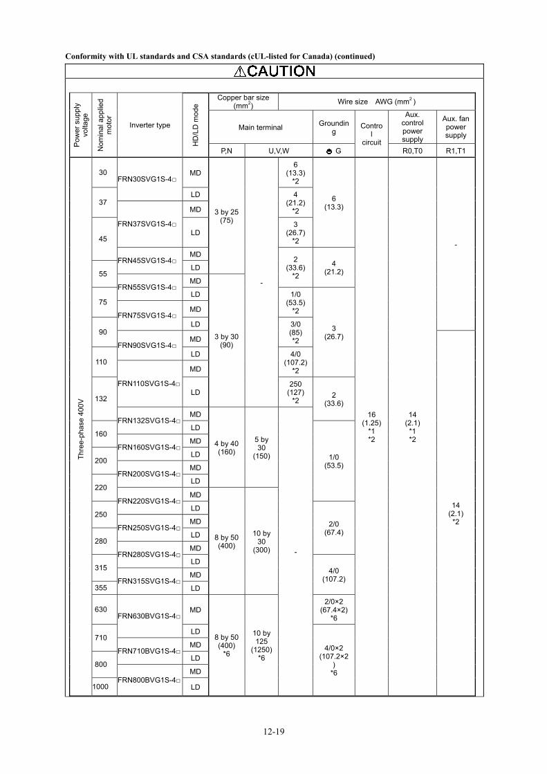
12-19
Conformity with UL standards and CSA standards (cUL-listed for Canada) (continued)
P
ower
sup
ply
volta
ge
Nom
inal
app
lied
mot
or
Inverter type
HD
/LD
mod
e
Copper bar size (mm2) Wire size AWG (mm2 )
Main terminal Grounding
Control
circuit
Aux. control power supply
Aux. fanpower supply
P,N U,V,W G R0,T0 R1,T1
Thre
e-ph
ase
400V
30 FRN30SVG1S-4□
MD
3 by 25(75)
-
6 (13.3)
*2
6 (13.3)
16 (1.25)
*1 *2
14 (2.1)
*1 *2
-
37 LD 4
(21.2)*2
FRN37SVG1S-4□
MD
45 LD
3 (26.7)
*2
FRN45SVG1S-4□ MD
2 (33.6)
*2
4 (21.2) 55
LD
FRN55SVG1S-4□ MD
3 by 30(90)
75 LD 1/0
(53.5)*2
3 (26.7)
FRN75SVG1S-4□ MD
90 LD 3/0
(85) *2 FRN90SVG1S-4□
MD
14 (2.1)
*2
110 LD 4/0
(107.2)*2
FRN110SVG1S-4□
MD
132 LD
250 (127)
*2 2
(33.6)
FRN132SVG1S-4□ MD
4 by 40(160)
5 by 30
(150)
-
160 LD
1/0 (53.5)
FRN160SVG1S-4□ MD
200 LD
FRN200SVG1S-4□ MD
220 LD
FRN220SVG1S-4□ MD
8 by 50(400)
10 by 30
(300)
250 LD
2/0 (67.4) FRN250SVG1S-4□
MD
280 LD
FRN280SVG1S-4□ MD
315 LD
4/0 (107.2) FRN315SVG1S-4□
MD
355 LD
630 FRN630BVG1S-4□
MD
8 by 50(400)
*6
10 by 125
(1250)*6
2/0×2 (67.4×2)
*6
710 LD
4/0×2 (107.2×2
) *6
FRN710BVG1S-4□ MD
800 LD
FRN800BVG1S-4□ MD
1000 LD

12-20
Conformity with UL standards and CSA standards (cUL-listed for Canada) (continued)
*1 No terminal end treatment is required for connection. *2 Use 75°C Cu wire only. *3 Supplier: Cooper Bussmann *4 6 rms Amperes for aux. control power supply. *5 5 rms Amperes for aux. control power supply. 12. Filter stack(RHF series) and peripheral devices of PWM converter(RHC series) are not contained in UL/cUL authorization range.
13. If the keypad is removed from the inverter and mounts it to the out of the cabinet, it will be out of UL/cUL authorization range.

High Power Factor PWM Converter, RHC-D Serieswith Power Regenerative Function (Stack Type)
Instruction ManualFirst Edition, April 2013Fourth Edition, July 2014
Fuji Electric Co., Ltd.
The purpose of this instruction manual is to provide accurate information in handling, setting up and operating of the converter and filter stack. Please feel free to send your comments regarding any errors or omissions you may have found, or any suggestions you may have for generally improving the manual.
In no event will Fuji Electric Co., Ltd. be liable for any direct or indirect damages resulting from the application of the information in this manual.

Fuji Electric Co., Ltd.
Gate City Ohsaki, East Tower, 11-2, Osaki 1-chome, Shinagawa-ku, Tokyo 141-0032, JapanURL http://www.fujielectric.com/
2014-07 (D13/D13)