high reliability low loss coaxial cable assemblies
TRANSCRIPT

GENERIC SPECIFICATION REF. : RAD-GEN-CSHF-001 Date: November, 20th 2020
ED/REV: 7/D
PAGE : 1/32
Reproduction interdite / Reproduction forbidden
Titre / Title
HIGH RELIABILITY
LOW LOSS COAXIAL
CABLE ASSEMBLIES
Rédigé par / Written by Responsabilité / Responsibility Date Signature
S. POIZAT
Space Project Manager 20/11/2020
Vérifié par / Verified by
V EUDELINE Space B. U. Manager 20/11/2020
Approuvée par / Approved by
C. DASPRES
Space Quality Manager 20/11/2020

GENERIC SPECIFICATION REF. : RAD-GEN-CSHF-001 Date: November, 20th 2020
ED/REV: 7/D
PAGE : 2/32
Reproduction interdite / Reproduction forbidden
DOCUMENTATION CHANGE NOTICE
REVISION OR
ISSUE
DATE CHANGE
4 -
5 -
5 A
6 –
7 – 7 A
7 B
7 C
7 D
24/10/12
03/06/2014
12/08/2015
15/02/2018
05/10/2018 19/10/2018
24/04/201
26/03/2020
20/11/2020
-Updated with new Radiall codification (§3): added two digits at the end and added SHF4.8MS codification, cancelled SHF4.2MS, 5MSLW2 and SHF13MS. - Updated sine vibration level: 30g instead of 26g - Updated random vibration level: 38.5 grms instead of 23.76grms - Updated Mechanical shock level: 800g, 0.3ms instead of 600g, 1ms Marking change: The Serial number configuration is modified (see §7.3) + add more information about marking type in function of the sign of ports if they are requested or not Delete Mechanical Shock during qualification test (according to ESCC requirement) Updated with: -Change of the qualification flow chart (identical at ESCC3408) -Added insertion loss stability criteria and procedure -Added new codifications for cable and connectors (§3.1 & 3.2) -Corrected the reference of IEC specification in §16.2: 61726 instead of 1726. -Corrected document: PAQP A 0019 (PID for SHF cable assemblies manufactured at Radiall IDA) replaced by PAQ CHR 0014 (PID for SHF cable assemblies manufactured by Radiall CHR) Updated to change the LAT chart: identical at ESCC3408 Updated with TAS recommendation: Add X-ray test at 100%, add Thermal cycling test in Final Production Test for FM Updated with minor correction: - §16.11 & 16.14: Added comments: Connect the connectors of
the cable assemblies under test with complementary savers or connectors during thermal cycling
- §16.18.1: Sine vibration: correction for typing error: 5Hz instead of 10Hz
- §16.12: Microsection: add of the number of sample to do Updated with: - Added new references documents in §2 - §16.4 & 16.5: added the number of frequency points : 401 pts
for EM, FM and LAT, and 801pts for Qualification - §16.9: Change requirement of drift variation of VSWR: 10%
instead of 5% Updated to add test set up for thermal cycles A, B & C (§16.11.1 to 16.11.3) and tested on operational temperature Added SMPM L codification and .047” & LPV cable code

GENERIC SPECIFICATION REF. : RAD-GEN-CSHF-001 Date: November, 20th 2020
ED/REV: 7/D
PAGE : 3/32
Reproduction interdite / Reproduction forbidden
Table of contents
1. SCOPE ................................................................................................................................................................................6
2. APPLICABLE AND REFERENCE DOCUMENTS ......................................................................................................6
3. CABLE ASSEMBLY PART NUMBERS ........................................................................................................................7
3.1. CABLE ASSEMBLY FOR FLIGHT MODEL (FM & EM) ...................................................................................................7
4. PIECE PART TECHNICAL DESIGN ............................................................................................................................8
4.1. COAXIAL CONNECTOR .................................................................................................................................................8 4.2. SHF COAXIAL CABLE ..................................................................................................................................................8
5. PIECE PART PROCUREMENT .....................................................................................................................................8
5.1. CONNECTOR ................................................................................................................................................................8 5.2. SHF COAXIAL CABLE ...................................................................................................................................................8
6. INSPECTION & RIGHTS ................................................................................................................................................8
7. REQUIREMENTS .............................................................................................................................................................8
7.1. SPECIFICATIONS ..........................................................................................................................................................9 7.1.1. Conditions and Methods of Test......................................................................................................................9 7.1.2. Manufacturer’s responsibility for performance of tests and inspections ....................................................9
7.2. DELIVERABLE COMPONENTS .......................................................................................................................................9 7.3. MARKING ......................................................................................................................................................................9 7.4. PHASE (APPLICABLE ONLY FOR FLIGHT MODEL) .....................................................................................................10
8. PRODUCTION CONTROL ...........................................................................................................................................10
9. FINAL PRODUCTION TESTS .....................................................................................................................................10
9.1. GENERAL ...................................................................................................................................................................10 9.2. TEST METHODS AND CONDITIONS ............................................................................................................................10 9.3. DOCUMENTATION ......................................................................................................................................................10
10. FAILURES ...................................................................................................................................................................10
10.1. LOT FAILURE FOR FINAL PRODUCTION TESTS: ....................................................................................................10 10.2. LOT FAILURE DURING 100 % TESTING FOR FINAL PRODUCTION TESTS .............................................................11 10.3. LOT FAILURE DURING SAMPLE TESTING FOR QUALIFICATION AND LOT ACCEPTANCE TESTS: ..........................11 10.4. FAILED COMPONENTS ...........................................................................................................................................11 10.5. FAILURE CRITERIA .................................................................................................................................................11
11. QUALIFICATION TESTS .........................................................................................................................................11
11.1. QUALIFICATION TESTING .......................................................................................................................................11 11.1.1. Sample Size .................................................................................................................................................11 11.1.2. Distribution within the Sample Lot for Qualification Testing ..................................................................11
11.2. DOCUMENTATION ..................................................................................................................................................12
12. LOT ACCEPTANCE TESTS .....................................................................................................................................12
12.1. LOT ACCEPTANCE TESTING ..................................................................................................................................12 12.1.1. Sample Size .................................................................................................................................................12 12.1.2. Distribution within the Sample Lot for Lot Acceptance Testing .............................................................12
12.2. DOCUMENTATION ..................................................................................................................................................12
13. FINAL PRODUCTION TEST FLOW CHART (100% TESTING) .......................................................................13

GENERIC SPECIFICATION REF. : RAD-GEN-CSHF-001 Date: November, 20th 2020
ED/REV: 7/D
PAGE : 4/32
Reproduction interdite / Reproduction forbidden
13.1. FOR ELECTRICAL MODEL (100% TESTING) ..........................................................................................................13 13.2. FOR FLIGHT MODEL (100% TESTING) ..................................................................................................................14
14. QUALIFICATION TEST FLOW CHART ...............................................................................................................15
15. LOT ACCEPTANCE TEST FLOW CHART ...........................................................................................................16
16. TESTS, METHODS AND PROCEDURES ...............................................................................................................17
16.1. VISUAL INSPECTION ...............................................................................................................................................17 16.2. SCREENING EFFECTIVENESS (IN REVERBERATION CHAMBER) ............................................................................17 16.3. DIELECTRIC WITHSTANDING VOLTAGE .................................................................................................................17 16.4. VSWR MEASUREMENT .........................................................................................................................................18 16.5. INSERTION LOSS MEASUREMENT .........................................................................................................................20 16.6. CABLE RETENTION FORCE .....................................................................................................................................20 16.7. BENDING TEST .......................................................................................................................................................21 16.8. VIBRATIONS ...........................................................................................................................................................21
16.8.1. Sine Vibrations .............................................................................................................................................21 16.8.2. Random vibrations ......................................................................................................................................21
16.9. INSERTION LOSS AND VSWR IN TEMPERATURE ..................................................................................................22 16.10. RADIOGRAPHIC INSPECTION (X-RAY) ...................................................................................................................23 16.11. THERMAL CYCLES .................................................................................................................................................24
16.11.1. Thermal Cycles- A .......................................................................................................................................24 16.11.2. Thermal Cycles- B .......................................................................................................................................24 16.11.3. Thermal Cycles- C ......................................................................................................................................24 16.11.4. Thermal Cycles- Final production test ......................................................................................................25
16.12. MICROSECTION ......................................................................................................................................................25 16.13. INSULATION RESISTANCE ......................................................................................................................................25 16.14. THERMAL STABILITY OF INSERTION LOSS ............................................................................................................25 16.15. AGEING ..................................................................................................................................................................26 16.16. MATING ENDURANCE .............................................................................................................................................26 16.17. CORONA .................................................................................................................................................................26 16.18. RF POWER HANDLING ..........................................................................................................................................27 16.19. MULTIPACTION .......................................................................................................................................................28 16.20. RF POWER CYCLING .............................................................................................................................................28 16.21. PERMANENCE OF MARKING ...................................................................................................................................29 16.22. MATING AND UNMATING FORCE .............................................................................................................................29 16.23. COUPLING PROOF TORQUE ...................................................................................................................................29 16.24. CABLE ASSEMBLY STABILITY UNDER AGITATION ...................................................................................................30
17. PACKAGING...............................................................................................................................................................32
18. DELIVERABLE DOCUMENTS ................................................................................................................................32
19. MOUNTING INSTRUCTIONS .................................................................................................................................32
20. ANGULAR POSITION FOR ANGLED CONNECTOR ASSEMBLIES ...............................................................32

GENERIC SPECIFICATION REF. : RAD-GEN-CSHF-001 Date: November, 20th 2020
ED/REV: 7/D
PAGE : 5/32
Reproduction interdite / Reproduction forbidden
LIST OF FIGURES Figure I (a) - SWEPT FREQUENCY TEST SET-UP – VECTORIAL METHOD (2 PORTS) ................................. 19 Figure I (b) - SWEPT FREQUENCY TEST SET-UP - VECTORIAL METHOD (1 PORT) .................................... 19 Figure II (a) - VECTORIAL METHOD OF RF INSERTION LOSS MEASUREMENTOF CABLE ASSEMBLIES .. 20
GENERIC SPECIFICATION REF. : RAD-GEN-CSHF-001 Date: November, 20th 2020
ED/REV: 7/D
PAGE : 6/32
Reproduction interdite / Reproduction forbidden
1. SCOPE
This specification covers the general requirements for procurement, including final production, lot acceptance and qualification testing, and delivery of flexible coaxial low loss cable assemblies to be used in « HI-REL » applications.
SHF cable assemblies are the assembly of coaxial connectors on low loss coaxial cables. All components of RADIALL cable assembly range are designed and manufactured in house.
The connectors are specially designed for SHF cables in order to offer the best VSWR. They are soldered on the cable to assume the best electrical continuity and in consequence a high screening effectiveness.
SHF cables use a wrapped low dielectric constant PTFE tape in order to get high precision of dimensions. This technology allows a very good repeatability of electrical and mechanical performances. The electrical shield is made with a Silver-Plated Copper tape wrapped on to the insulator with dedicated machines and tools.
This specification contains the appropriate inspection and test schedules and also specifies the data documentation requirements. Cable assemblies are delivered under RADIALL Quality Assurance Label.
2. APPLICABLE AND REFERENCE DOCUMENTS The latest issue for these documents is applicable:
APPLICABLE DOCUMENT
RQM RADIALL Quality manual
PAQ CHR 0014 PID for SHF cable assemblies
IEC Publication No 410 Sampling plans and procedures for inspection by attributes
REFERENCE DOCUMENT
ESCC 20600 Preservation, packaging and despatch of SCC Electronic Components
ESCC 3408 General specification for RF Cables Assemblies
ESCC 3402 General Specification for Connectors, Coaxial, Radio-frequency
ESCC 3902 General specification for Cables, Coaxial, Radio Frequency Fexible
MIL DTL 17 General specification for Cables, Radio frequency, Flexible and semi-rigid,
MIL-STD-348 Radio Frequency connector - Interfaces
GENERIC SPECIFICATION REF. : RAD-GEN-CSHF-001 Date: November, 20th 2020
ED/REV: 7/D
PAGE : 7/32
Reproduction interdite / Reproduction forbidden
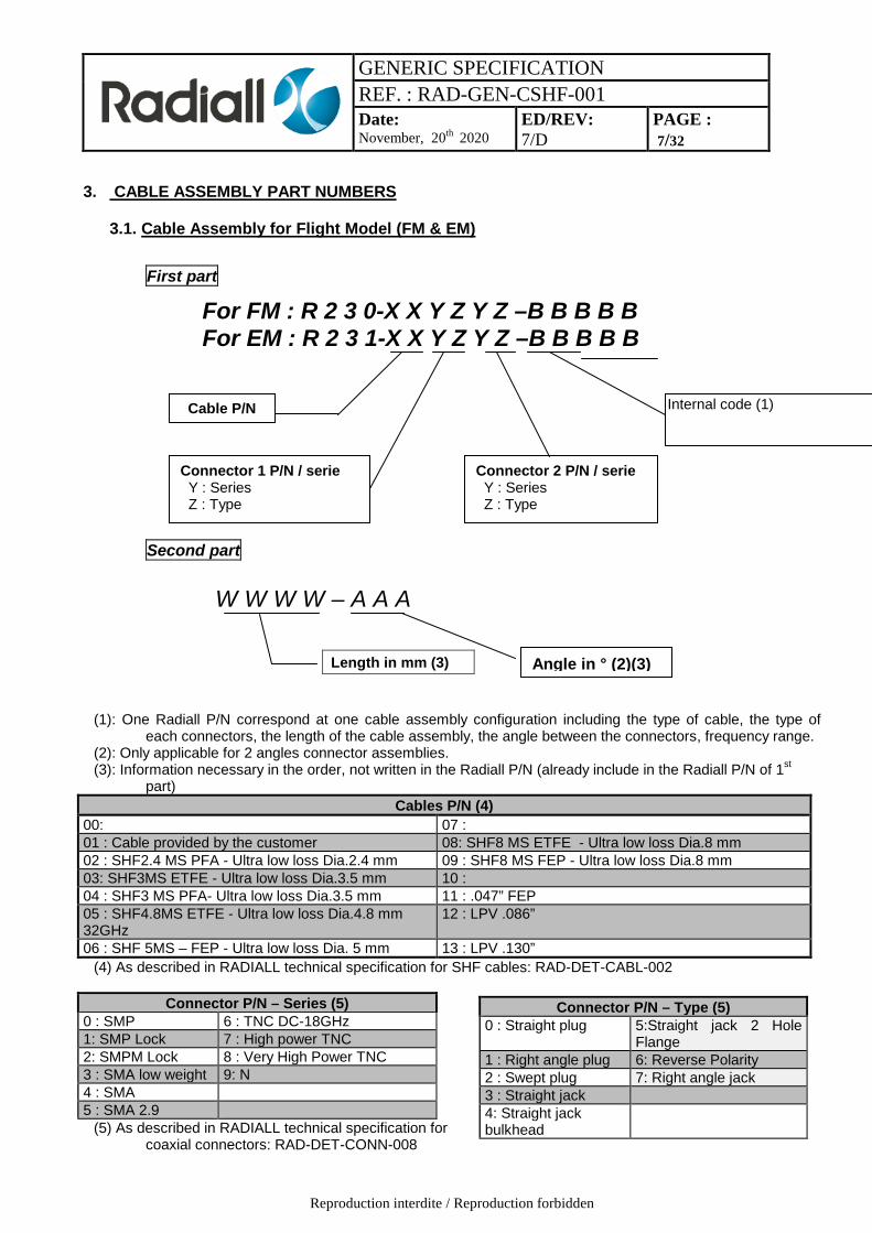
3. CABLE ASSEMBLY PART NUMBERS
3.1. Cable Assembly for Flight Model (FM & EM) First part
Second part (1): One Radiall P/N correspond at one cable assembly configuration including the type of cable, the type of
each connectors, the length of the cable assembly, the angle between the connectors, frequency range. (2): Only applicable for 2 angles connector assemblies. (3): Information necessary in the order, not written in the Radiall P/N (already include in the Radiall P/N of 1st
part) Cables P/N (4)
00: 07 : 01 : Cable provided by the customer 08: SHF8 MS ETFE - Ultra low loss Dia.8 mm 02 : SHF2.4 MS PFA - Ultra low loss Dia.2.4 mm 09 : SHF8 MS FEP - Ultra low loss Dia.8 mm 03: SHF3MS ETFE - Ultra low loss Dia.3.5 mm 10 : 04 : SHF3 MS PFA- Ultra low loss Dia.3.5 mm 11 : .047” FEP 05 : SHF4.8MS ETFE - Ultra low loss Dia.4.8 mm 32GHz
12 : LPV .086”
06 : SHF 5MS – FEP - Ultra low loss Dia. 5 mm 13 : LPV .130” (4) As described in RADIALL technical specification for SHF cables: RAD-DET-CABL-002
Connector P/N – Series (5) 0 : SMP 6 : TNC DC-18GHz 1: SMP Lock 7 : High power TNC 2: SMPM Lock 8 : Very High Power TNC 3 : SMA low weight 9: N 4 : SMA 5 : SMA 2.9
(5) As described in RADIALL technical specification for coaxial connectors: RAD-DET-CONN-008
For FM : R 2 3 0-X X Y Z Y Z –B B B B B For EM : R 2 3 1-X X Y Z Y Z –B B B B B
Connector P/N – Type (5) 0 : Straight plug 5:Straight jack 2 Hole
Flange 1 : Right angle plug 6: Reverse Polarity 2 : Swept plug 7: Right angle jack 3 : Straight jack 4: Straight jack bulkhead
Length in mm (3)
W W W W – A A A
Angle in ° (2)(3)
Cable P/N
Connector 1 P/N / serie Y : Series Z : Type
Connector 2 P/N / serie Y : Series Z : Type
Internal code (1)

GENERIC SPECIFICATION REF. : RAD-GEN-CSHF-001 Date: November, 20th 2020
ED/REV: 7/D
PAGE : 8/32
Reproduction interdite / Reproduction forbidden
4. PIECE PART TECHNICAL DESIGN
4.1. Coaxial Connector
All the technical requirements and dimensions are described in RADIALL Technical Specification for coaxial connectors RAD-DET-CONN-008
4.2. SHF Coaxial Cable
All the technical requirements, dimensions, electrical and mechanical parameters are described in RADIALL Technical Specification for SHF coaxial cable RAD-DET-CABL-002
5. PIECE PART PROCUREMENT
5.1. Connector
Piece part Inspection and control Document reference Connector Visual
Conformity of plating Dimensions Electrical tests
PAQ A 0010 for all cable assemblies Refer to PQAP and RADIALL technical specification for coaxial connectors
5.2. SHF Coaxial cable
Piece part Inspection and control Document reference SHF Cable Visual
Dimensions Inspection tests
Refer to PQAP, RADIALL technical specification for procurement of SHF coaxial cables
6. INSPECTION & RIGHTS RADIALL shall be responsible of inspections performed during the complete manufacturing, the Final Production Tests and Lot Acceptance Tests.
7. REQUIREMENTS The test requirements for procurement of qualified components shall only comprise Final Production Tests. Connectors and cables could be also provided from different identified batches of previous manufacturing lots. For LAT test (shall be specified in the order), the applicable tests shall included Final Production Test and LAT Tests. For Qualification (shall be specified in the order), the applicable tests shall included Final Production Tests and Qualification tests.

GENERIC SPECIFICATION REF. : RAD-GEN-CSHF-001 Date: November, 20th 2020
ED/REV: 7/D
PAGE : 9/32
Reproduction interdite / Reproduction forbidden
7.1. Specifications
Procurement and delivery of components shall be in conformity with this specification which shall apply in total unless otherwise specified in Detail Specification.
7.1.1. Conditions and Methods of Test
The conditions and methods of test shall be in accordance with the Product Quality Plan.
7.1.2. Manufacturer’s responsibility for performance of tests and inspections
RADIALL shall be responsible for the performance of tests and inspections. These tests and inspections shall be performed in house. For qualification and Lot acceptance tests, tests could be performed by agreed external facilities.
7.2. Deliverable components
Cable assemblies delivered to this specification shall be processed in accordance with the relevant Product Quality Plan. Each delivered coaxial cable shall be traceable to its production lot. Coaxial cables delivered to this specification shall have completed satisfactorily all tests with the relevant testing level. If required in the order, Lot Acceptance Testing shall be performed after the complete manufacturing (assembly and final production tests).
7.3. Marking
Unless otherwise specified by the customer, the cable assemblies shall be marked with the following data: - Radiall P/N: RXXXXXXXXXXXXX - YYYY
-The lot number: year + week (4 digits) followed by Serial number (7 to 9 digits) Example: R23006404000001-1000
1243 7830368 The serial number corresponds to the reference of Radiall order production. For each Radiall order production, there is ONLY one cable assembly. In this case, this number is unique. The number of the radiall order production is incremented automatically by the Radiall ERP for each cable assembly to be manufactured.
Note 1: The marking is made on space qualified heat shrink tubes at each end of the cable. Note 2: The coaxial cable assembly identification must be read from connector A to connector B.
Connector A Connector BMarking area

GENERIC SPECIFICATION REF. : RAD-GEN-CSHF-001 Date: November, 20th 2020
ED/REV: 7/D
PAGE : 10/32
Reproduction interdite / Reproduction forbidden
If there is a customer P/N (or sign of cable) requested without sign of ports, the marking will be done on two sleeves on each extremity of the cable assembly like it is shown on the figure above. If there are signs of ports requested, the main marking as defined §7.3 will be placed on the middle of the cable assembly (included the customer P/N or sign of cable is requested), and two others sleeves on each extremity of the cable will be placed with the sign of port requested. For all others configurations of marking, please contact Radiall.
7.4. Phase (Applicable only for Flight Model)
Radiall can manufacture the cable assemblies (same type of cable with same types of connectors) matched in phase. The tolerances of the phase matched (±x°) depends of the type of cable, the length of the cable assemblies and the frequency point of measurement. All these information’s are available under request, for that, please contact directly our marketing department. For the absolute phase, please contact directly our marketing department for more information. In case of contradiction between physical length requested by the customer and the phase delay specifications, the phase delay is only the one to be considered, the physical length shall be indicated as a rough order of magnitude.
8. PRODUCTION CONTROL The minimum requirements for production control are defined in the Product Quality Plan.
9. FINAL PRODUCTION TESTS
9.1. General All cable assemblies used for delivery and those submitted to Lot Acceptance Test, shall be subjected to tests and inspections in accordance with the Paragraph 13 of this specification.
9.2. Test Methods and Conditions Test methods and conditions are completely specified in the Product Quality Plan. Compiled test conditions are specified and performed in the order shown in the paragraph referenced in Final Production Test chart.
9.3. Documentation Documentation of Final Production Test data shall be in accordance with the requirements of Para. 18 of this specification.
10. FAILURES A component shall be counted as a failure in any of the following cases: - Mechanical failure, - Handling failure, - Lost components
10.1. Lot Failure for Final Production Tests: In case of lot failure, the manufacturer shall alert the Orderer. A lot shall be considered as failed if the allowable number defined in the paragraph 10-2 has been exceeded.
GENERIC SPECIFICATION REF. : RAD-GEN-CSHF-001 Date: November, 20th 2020
ED/REV: 7/D
PAGE : 11/32
Reproduction interdite / Reproduction forbidden
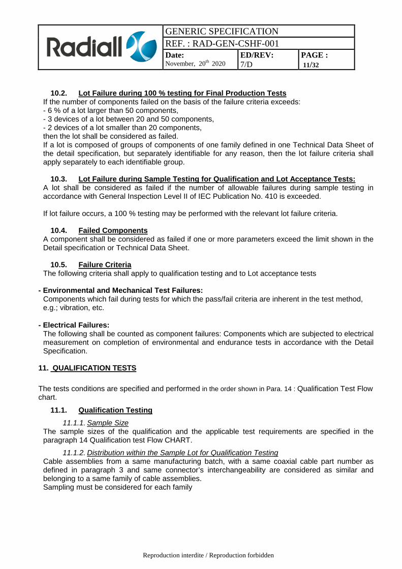
10.2. Lot Failure during 100 % testing for Final Production Tests If the number of components failed on the basis of the failure criteria exceeds: - 6 % of a lot larger than 50 components, - 3 devices of a lot between 20 and 50 components, - 2 devices of a lot smaller than 20 components, then the lot shall be considered as failed. If a lot is composed of groups of components of one family defined in one Technical Data Sheet of the detail specification, but separately identifiable for any reason, then the lot failure criteria shall apply separately to each identifiable group.
10.3. Lot Failure during Sample Testing for Qualification and Lot Acceptance Tests: A lot shall be considered as failed if the number of allowable failures during sample testing in accordance with General Inspection Level II of IEC Publication No. 410 is exceeded. If lot failure occurs, a 100 % testing may be performed with the relevant lot failure criteria.
10.4. Failed Components A component shall be considered as failed if one or more parameters exceed the limit shown in the Detail specification or Technical Data Sheet.
10.5. Failure Criteria The following criteria shall apply to qualification testing and to Lot acceptance tests
- Environmental and Mechanical Test Failures:
Components which fail during tests for which the pass/fail criteria are inherent in the test method, e.g.; vibration, etc.
- Electrical Failures: The following shall be counted as component failures: Components which are subjected to electrical measurement on completion of environmental and endurance tests in accordance with the Detail Specification.
11. QUALIFICATION TESTS The tests conditions are specified and performed in the order shown in Para. 14 : Qualification Test Flow chart.
11.1. Qualification Testing 11.1.1. Sample Size
The sample sizes of the qualification and the applicable test requirements are specified in the paragraph 14 Qualification test Flow CHART.
11.1.2. Distribution within the Sample Lot for Qualification Testing Cable assemblies from a same manufacturing batch, with a same coaxial cable part number as defined in paragraph 3 and same connector’s interchangeability are considered as similar and belonging to a same family of cable assemblies. Sampling must be considered for each family
GENERIC SPECIFICATION REF. : RAD-GEN-CSHF-001 Date: November, 20th 2020
ED/REV: 7/D
PAGE : 12/32
Reproduction interdite / Reproduction forbidden
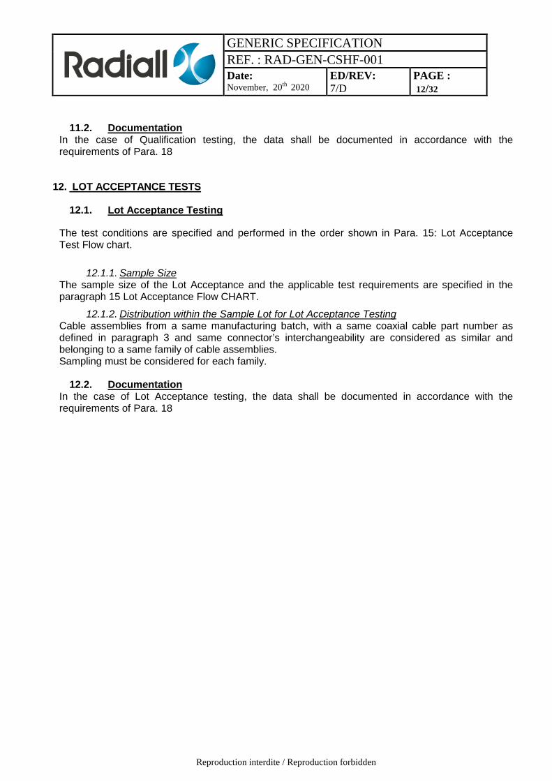
11.2. Documentation In the case of Qualification testing, the data shall be documented in accordance with the requirements of Para. 18
12. LOT ACCEPTANCE TESTS
12.1. Lot Acceptance Testing
The test conditions are specified and performed in the order shown in Para. 15: Lot Acceptance Test Flow chart.
12.1.1. Sample Size The sample size of the Lot Acceptance and the applicable test requirements are specified in the paragraph 15 Lot Acceptance Flow CHART.
12.1.2. Distribution within the Sample Lot for Lot Acceptance Testing Cable assemblies from a same manufacturing batch, with a same coaxial cable part number as defined in paragraph 3 and same connector’s interchangeability are considered as similar and belonging to a same family of cable assemblies. Sampling must be considered for each family.
12.2. Documentation In the case of Lot Acceptance testing, the data shall be documented in accordance with the requirements of Para. 18

GENERIC SPECIFICATION REF. : RAD-GEN-CSHF-001 Date: November, 20th 2020
ED/REV: 7/D
PAGE : 13/32
Reproduction interdite / Reproduction forbidden
13. FINAL PRODUCTION TEST FLOW CHART (100% TESTING)
13.1. For Electrical Model (100% testing)
According to applicable Technical
Data Sheet

GENERIC SPECIFICATION REF. : RAD-GEN-CSHF-001 Date: November, 20th 2020
ED/REV: 7/D
PAGE : 14/32
Reproduction interdite / Reproduction forbidden
13.2. For Flight Model (100% testing)
(1) Test applied on 5% in each order
According to applicable Technical
Data Sheet

GENERIC SPECIFICATION REF. : RAD-GEN-CSHF-001 Date: November, 20th 2020
ED/REV: 7/D
PAGE : 15/32
Reproduction interdite / Reproduction forbidden
14. QUALIFICATION TEST FLOW CHART
+
Note: 1/ Not failure is permitted 2/ A control sample shall be used for reference purposes. Whenever
electrical measurements are made on any component under test, the control sample shall also be measured.
3/ Only if ordered by the customer. 4/ The tests shown in this chart are considered to be destructive and
therefore components so tested shall not be used as flight model
6 TVs 2 TVs
1 TV

GENERIC SPECIFICATION REF. : RAD-GEN-CSHF-001 Date: November, 20th 2020
ED/REV: 7/D
PAGE : 16/32
Reproduction interdite / Reproduction forbidden
15. LOT ACCEPTANCE TEST FLOW CHART
Note: 1/ The quantity of test vehicles (TV) to be subjected to each test or subgroup test sequence is
indicated in Chart LAT 2/ Not failure is permitted 3/ A control sample shall be used for reference purposes. Whenever electrical
measurements are made on any component under test, the control sample shall also be measured.
4/ Only if specified in the Detail Specification and ordered by the customer (quoted as an option)
4 TVs 1 TV
3 TVs

GENERIC SPECIFICATION REF. : RAD-GEN-CSHF-001 Date: November, 20th 2020
ED/REV: 7/D
PAGE : 17/32
Reproduction interdite / Reproduction forbidden
16. TESTS, METHODS AND PROCEDURES
16.1. Visual Inspection
This inspection shall be done by naked eyes (NE): • Aspect of cable shall be free of any visual defect like stripes, pleats, notches that could impact the good working of the cable assembly. • The marking on the thermal sleeves shall meet the requirements. • Aspect of connectors shall meet the criteria required in MIL-PRF-39012 Specification (visual inspection of connector interfaces for plating damage, contamination and excessive wear should be carried out). • All parts of cable assembly shall be cleaned, particularly in the connector interface areas. • Connector orientation in accordance with customer requirements.
16.2. Screening Effectiveness (in reverberation chamber)
The method consists of placing the component under test in a quasi-homogeneous and isotropic electromagnetic field, so that the orientation and polarisation of the incident field do not influence the measurement. These conditions are achieved using an over sized cavity, called reverberation chamber, coupled to a generator through a matched antenna. A mode stirrer (rotating reflector) which incessantly provides modifications of the geometrical structure of the cage, is used in order to get an homogeneous field. Frequency range of the reverberant chamber: 500Mhz to 40 GHz Number of measurement points: 100 pts/decade. The screening effectiveness (SE) is done by the formula: SE (dB) = (Pi/Pt) dB - Xc Where Pi is the incident Power (from the generator) Pt is the transmitted Power to the component Xc is the cage Loss (dB). Xc measured with an additional matched antenna in the chamber. Test fixture and method according to IEC Technical Report: IEC 61726
16.3. Dielectric Withstanding Voltage
Method - Test according to MIL C 17 - - Test voltage :AC 50 Hz, according to cable assembly Detail Specification. Requirement No breakdown after 1mn.

GENERIC SPECIFICATION REF. : RAD-GEN-CSHF-001 Date: November, 20th 2020
ED/REV: 7/D
PAGE : 18/32
Reproduction interdite / Reproduction forbidden
16.4. VSWR Measurement
The reflection coefficient or VSWR shall be measured in accordance with one of the following methods: - Vector method (test set-up shown in Figure I(a) or I (b), Across the full frequency range by the swept frequency technique or, alternatively, with
- 401pts minimum across the frequency range for Electrical, Flight Model and Lot Acceptance Test
- 801 pts minimum across the frequency range for qualification test The measured values shall not exceed those given in the Detail Specification. The cable assembly must be connected to the standard precision adapter No. 3 (see figure I (a) or I (b)).

GENERIC SPECIFICATION REF. : RAD-GEN-CSHF-001 Date: November, 20th 2020
ED/REV: 7/D
PAGE : 19/32
Reproduction interdite / Reproduction forbidden
Figure I (a) - SWEPT FREQUENCY TEST SET-UP – VECTORIAL METHOD (2 PORTS)
POSSIBLE CALIBRATION PLANES OF FULL TWO PORTS CALIBRATION
Figure I (b) - SWEPT FREQUENCY TEST SET-UP - VECTORIAL METHOD (1 PORT)
POSSIBLE CALIBRATION PLANES OF S11 CALIBRATION (REFLECTION) REQUIREMENT: According to Detail Specification of cable assemblies.
1 I II
2
3 DUT
2
4
5
1 : Vector network analyser with RF generator and S parameter test set. 2-5 : Cable assemblies. 3-4 : Standard precision adapters
1 I II
2
3 DUT
2
4
5
1 : Vector network analyser with RF generator and S parameter test set. 2: Cable assembly 3-4 : Standard precision adapters 5 : Precision termination (reflection coefficient <0.017 (-35 dB) in the test frequency range

GENERIC SPECIFICATION REF. : RAD-GEN-CSHF-001 Date: November, 20th 2020
ED/REV: 7/D
PAGE : 20/32
Reproduction interdite / Reproduction forbidden
16.5. Insertion Loss Measurement
The cable assemblies shall be tested as shown in Figure II (a). This measure includes the reflection losses of the cable assembly and dissipating losses.
Procedure: The equipment is calibrated. Insert the cable assembly between the two ports. The insertion losses of the cable assembly are measured and the values are recorded. Measurement shall be performed across the full frequency range by the swept frequency technique or, alternatively, with:
- 401pts minimum across the frequency range for Electrical, Flight Model and Lot Acceptance Test
- 801 pts minimum across the frequency range for qualification test
Requirement: According to Detail Specification of cable assemblies.
Figure II (a) - VECTORIAL METHOD OF RF INSERTION LOSS MEASUREMENTOF CABLE ASSEMBLIES
POSSIBLE CALIBRATION PLANES OF FULL TWO PORTS CALIBRATION
16.6. Cable retention force Method: - VSWR measurement according to paragraph 16-4 - When the cable assembly is fixed at one end, it shall be in a vertical state. - Apply, for 2 minutes, a force F at the other end. - Force: Specified according to Detail Specification of cable assemblies. - VSWR measurement according to 16-4. Requirement - VSWR according to Detail Specification of cable assemblies. - Interface dimensions.
1 I II
2
3 DUT
2
4
5
1 : Vector network analyser with RF generator and S parameter test set. 2-5 : Cable assemblies. 3-4 : Standard precision adapters

GENERIC SPECIFICATION REF. : RAD-GEN-CSHF-001 Date: November, 20th 2020
ED/REV: 7/D
PAGE : 21/32
Reproduction interdite / Reproduction forbidden
-
16.7. Bending test
Method The cable assembly is wrapped and unwrapped (one turn) five times around the minimum bending dynamic radius of the relevant cable. See Detail Specification of cable assemblies. Requirement - No crack on the jacket. - VSWR and insertion loss and screening effectiveness according to Detail Specification of cable assemblies. - Interface dimensions.
16.8. Vibrations
According to MIL-PRF 39 012 § 4.6.15 REQUIREMENT: No discontinuity greater than 1 µs shall appear during the test. No visible damage on the cable assembly shall appear. During these tests, any continuity between the central and external conductors shall be checked, under a current of 100 mA max.
16.8.1. Sine Vibrations
Along 3 axes: - Frequency range and level 5 - 26 Hz : ± 11 mm 26-100 Hz : 30 g
- Sweep frequency: 5-100-5Hz. For the entire frequency range of 5 to 100Hz and return to 5Hz, The slope rate shall be 2 oct/mn maximum - Total number of cycles: 9 (3 times in each of the 3 mutually perpendicular axes) - Clamping of cable at about 15cm of the vibrating part.
16.8.2. Random vibrations
Perpendicular & Parallel axes to the mounting plane
Range (Hz) PSD Level
20 – 60 60 – 400 400 –800
800 – 1000 1000 –2000
+ 6 dB/oct. 2 g²/Hz
- 6 dB/oct. 0.5 g²/Hz -6 dB/oct.
Global : 38.5 g RMS
Duration = 180s per axis

GENERIC SPECIFICATION REF. : RAD-GEN-CSHF-001 Date: November, 20th 2020
ED/REV: 7/D
PAGE : 22/32
Reproduction interdite / Reproduction forbidden
16.9. Insertion Loss and VSWR in temperature
The cable assembly shall be submitted to the following cycles:
Test Parameters Parameters Tolerances Ts: Stabilisation time (hour) 1 / Cycle Number 3 / TOH: Temperature Operation High (°C) See TDS -0 / +3
Ambient (°C) 22 +3 / -3 TOL: Temperature Operation Low (°C) See TDS +0 / -3
Test method: - These RF measurements shall be performed with two cable assemblies (in orange colors in figure on next page) of 1 to 1.5m to link the VNA cable to the DUT - The VNA shall be calibrated with their own cables (purple colors in figure on next page) - The DUT with their two cables of 1 / 1.5m connected is placed in the thermal chamber. Only the extremities of the two cables are out of the thermal chamber, see figure on next page - The VNA cable are connected on the two cables of the DUT - The RF measurements include the RF performances of the two cables and the DUT. - The RF tests results will be a comparison between the measurements at room, High and Low temperature.
Temperature change rate ∆T/∆t = 5°C/mn ±2°C/mn
Ambient
Atmospheric Vacuum
Time (h)
Pressure
N Cycles
Time (h)
T(°c)
RF measurements: Insertion Loss and VSWR, included the measurement cables, see figure below Ts
TOH
TOL
Ts
RF measurements without the measurement cables

GENERIC SPECIFICATION REF. : RAD-GEN-CSHF-001 Date: November, 20th 2020
ED/REV: 7/D
PAGE : 23/32
Reproduction interdite / Reproduction forbidden
Figure of this setup
COMMAND CONDITIONS SANCTION UNIT
Min Max
RF MEASUREMENTS Insertion Loss See TDS for frequency range
∆ILT ≤0.25%/°C dB
VSWR See TDS for frequency range
No significant variation (∆VSWRT ≤10%) -
16.10. Radiographic Inspection (X-Ray)
Radiographic examination shall be performed on both cable-to-connector connections for each RF cable assembly. As a minimum, radiographs of solder joints shall be taken perpendicularly to the centreline of the connectors as follows:
• The solder joint between the outer conductor of the cable and the connector body, if one exists. • The solder joint between the centre conductor of the cable and the centre conductor of the
connector, if one exists. The radiographs shall be examined against the following acceptance criteria:
• There shall be no evidence of solder projections, spikes, splashes or loose particles. • Centre conductor :
• The centre conductor of the cable shall be inserted into the contact hole for a minimum of 80% of the cavity length. • The centre conductor of the cable shall present a straight shape in the connector. • The solder in the joint between the pin and the cable centre conductor shall show a
maximum of 30% voids within the solder joint. • The solder in the joint between the pin and the cable centre conductor shall not show a
single void bigger than 25% within the solder joint

GENERIC SPECIFICATION REF. : RAD-GEN-CSHF-001 Date: November, 20th 2020
ED/REV: 7/D
PAGE : 24/32
Reproduction interdite / Reproduction forbidden
• Outer conductor :
• The outer conductor shall be inserted into the connector body or ferrule with a minimum of 70% of dedicated length. • The outer conductor to connector body joint shall show a maximum of 30% voids within the
solder joint • The outer conductor to connector body joint shall not show a single void bigger than 25%
within the solder joint.
Any bend of the cable in 90° connector types shall be smooth and continuous, with uniform foil overlap and braid lay.
16.11. Thermal Cycles
16.11.1. Thermal Cycles- A
- Number of Temperature Cycles: 25 cycles with 15 minutes minimum at each Operating temperature as specified in the Technical Data Sheet.
- Temperature transfer slope: ≤ 10°C/minute - Connect the connectors of the cable assemblies on the opposite connectors fixed on
a base plate with ty-rap during the thermal cycling according to the User’s Handbook - Data Points:
On completion of testing and after a recovery period of 2 hours minimum at room temperature conditions, the test vehicles shall be visually examined and there shall be no evidence of damage or loosening of parts. VSWR and Insertion Loss shall be measured at Tamb = +22 ±3°C
16.11.2. Thermal Cycles- B
- Number of Temperature Cycles: 200 cycles with 15 minutes minimum at each
Operating temperature as specified in the Technical Data Sheet. - Temperature transfer slope: ≤ 10°C/minute - Connect the connectors of the cable assemblies on the opposite connectors fixed on
a base plate with ty-rap an during the thermal cycling according to the User’s Handbook
- Data Points: On completion of testing and after a recovery period of 2 hours minimum at room temperature conditions, the test vehicles shall be visually examined and there shall be no evidence of damage or loosening of parts. VSWR and Insertion Loss shall be measured at Tamb = +22 ±3°C
16.11.3. Thermal Cycles- C
- Number of Temperature Cycles: 100 cycles with 15 minutes minimum at each
Operating temperature as specified in the Technical Data Sheet. - Temperature transfer slope: ≤ 10°C/minute - Connect the connectors of the cable assemblies on the opposite connectors fixed on
a base plate with ty-rap during the thermal cycling according to the User’s Handbook

GENERIC SPECIFICATION REF. : RAD-GEN-CSHF-001 Date: November, 20th 2020
ED/REV: 7/D
PAGE : 25/32
Reproduction interdite / Reproduction forbidden
- Data Points:
On completion of testing and after a recovery period of 2 hours minimum at room temperature conditions, the test vehicles shall be visually examined and there shall be no evidence of damage or loosening of parts. VSWR and Insertion Loss shall be measured at Tamb = +22 ±3°C
16.11.4. Thermal Cycles- Final production test
- Number of Temperature Cycles: 3 cycles with 15 minutes minimum at each storage temperature extreme as specified in the Technical Data Sheet.
- Temperature transfer slope: ≤ 10°C/minute - Connect the connectors of the cable assemblies under test with complementary
savers or connectors during thermal cycling - Data Points:
On completion of testing and after a recovery period of 2 hours minimum at room temperature conditions, the test vehicles shall be visually examined and there shall be no evidence of damage or loosening of parts. VSWR and Insertion Loss shall be measured at Tamb = +22 ±3°C
16.12. Microsection
Microsection shall be performed on a longitudinal axis. A visual inspection is performed and no visible damage shall appear.
16.13. Insulation Resistance
Insulation resistance shall be tested in accordance with MIL-C-17. The insulation resistance between the inner and outer conductor of each cable assembly shall be not less than 200 MΩ under a voltage of 500Vdc. The measurements shall be read after 1 minute of voltage application.
16.14. Thermal Stability of Insertion Loss
Test vehicles shall be subjected to temperature cycling with the following conditions: - Number of Temperature Cycles: 3 cycles with 15 minutes minimum at each operating
temperature extreme as specified in Maximum Ratings in the Detail Specification. - Temperature transfer slope: 3 ±1°C/minute - Power Applied During Cycling: 0dBm minimum.
Operating Frequency: the maximum operating frequency as specified in the Detail Specification, unless otherwise specified.
- Data Points: During testing, Insertion Loss shall be continuously monitored and recorded once every 500ms as a minimum or alternatively an analogue recorder may be used. The following acceptance criteria shall apply:
- No single Insertion loss discontinuity, step or spike shall exceed 0.1dB. NOTE: In order for any observed glitch to be considered as a single Insertion Loss discontinuity, step or spike, it shall be evident on more than one temperature cycle. Otherwise it may be ignored.

GENERIC SPECIFICATION REF. : RAD-GEN-CSHF-001 Date: November, 20th 2020
ED/REV: 7/D
PAGE : 26/32
Reproduction interdite / Reproduction forbidden
16.15. Ageing
MIL-STD-202, Test Method 108 (non-operating) and as follows: - Test Temperature: maximum storage temperature specified in Maximum Ratings in
the Detail Specification - Duration: 240h - Connect the connectors of the cable assemblies on the opposite connectors during
the test. - Data Points:
On completion of testing and after a recovery period of 2 hours minimum at room temperature conditions, VSWR and Insertion Loss shall be measured at Tamb = +22 ±3°C.
16.16. Mating endurance
Mating Endurance shall be performed in accordance with Endurance as specified in Radiall Generic Specification n° RAD-GEN-CONN-001, and as follows:
- Cycle Rate: ≤ 12/minute - Number of Mating/Unmating Cycles: 50
One connector of each connector type in each test vehicle shall be tested:
16.17. Corona
Only required if ordered by the customer. Test vehicles shall be subjected to corona testing under thermal vacuum in accordance with the following conditions:
- Mounting: The test vehicles shall be mounted in a thermal vacuum chamber by means of a port-plate. The chamber shall be filled with air or dry nitrogen. Precautions shall be taken to avoid any condensation during testing.
- Test Conditions: - Test temperature shall be +22 ±3°C (at sensor Sr). - The maximum RF power level without corona breakdown as specified in the
Technical Data Sheet. - Operating frequency: 1GHz, CW mode. - Vacuum pumping sequence: start pumping from ambient pressure, while RF
power is ON. Once the pressure in the vacuum chamber has reached 5mPa, maintain the RF power for duration of 1 hour.

GENERIC SPECIFICATION REF. : RAD-GEN-CSHF-001 Date: November, 20th 2020
ED/REV: 7/D
PAGE : 27/32
Reproduction interdite / Reproduction forbidden
- Data Points:
During testing, Insertion Loss and VSWR shall be continuously monitored and recorded once every 500ms as a minimum or alternatively an analogue recorder may be used. Measurements shall meet the limits specified in the Technical Data Sheet. During testing, the test vehicles shall be continuously monitored and there shall be no corona breakdown/discharge. Corona breakdown/discharge shall be detected using an appropriate method (e.g. Global method based on the RF signal analysis: Transmit power, Reflected power, 3rd harmonic, phase nulling, Close-to-carrier noise, Local methods: Optical detection, Electron probe). On completion of testing and after a recovery period of 2 hours minimum at room temperature conditions, unless otherwise specified, Dielectric Withstanding Voltage, Voltage Proof Leakage Current, Insulation Resistance, VSWR and Insertion Loss shall be measured at Tamb = +22 ±3°C as specified in Technical Data Sheet.
16.18. RF Power Handling
Only required if ordered by the customer. Test vehicles shall be subjected to an RF power handling test under thermal vacuum in accordance with the following requirements:
- Mounting: Test vehicles shall be mounted in a vacuum chamber on thermally conductive brackets. Precaution shall be taken to avoid thermal conduction of the cable through the base plate. Poor thermally conductive stand-off supports are recommended to hold the cable. Temperature of the base plate should be monitored when applicable.
- Pre-test Venting: Unless otherwise specified, the test vehicles shall be vented for the purpose of outgassing, for a minimum duration of 24 hours prior to application of RF power, in a vacuum of ≤ 1mPa, at Tamb specified in the Detail specification.
- Test Conditions: - Test temperature: As specified in the Technical Data Sheet (at sensor Sr). - Test pressure: ≤ 1mPa. - After thermal stabilisation of the test vehicles at the test temperature, rated RF
power as specified in the Technical Data Sheet shall be applied. - Operating Frequency: the maximum operating frequency as specified in the
Technical Data Sheet, unless otherwise specified. - Test duration: 6 hours.
- Data Points:
During testing, Insertion Loss and VSWR shall be shall be continuously monitored and recorded once every 500ms as a minimum or alternatively an analogue recorder may be used. Measurements shall meet the limits specified in Technical Data Sheet. During testing, the test vehicles shall be monitored and there shall be no corona breakdown/discharge. Corona breakdown/discharge shall be detected using an appropriate method (e.g. Global method based on the RF signal analysis: Transmit power, Reflected power, 3rd harmonic, phase nulling, Close-to-carrier noise; Local method: Optical detection, Electron probe). On completion of testing and after a recovery period of 2 hours minimum at room temperature conditions, unless otherwise specified, Dielectric Withstanding Voltage, Voltage Proof Leakage Current, Insulation Resistance, VSWR and Insertion Loss shall be measured at Tamb = +22 ±3°C as specified in Technical Data Sheet.

GENERIC SPECIFICATION REF. : RAD-GEN-CSHF-001 Date: November, 20th 2020
ED/REV: 7/D
PAGE : 28/32
Reproduction interdite / Reproduction forbidden
16.19. Multipaction
Only required if ordered by the customer. A multipaction test shall be performed in accordance with ECSS-E-20-01. The multipaction classification of component type shall be as specified in the Technical Data Sheet. Unless otherwise specified, the following conditions shall apply:
- Applied Power: Rated RF pulse power as specified in Maximum Ratings in the Technical Data Sheet and Detail specification.
- Test Temperatures: at maximum temperature without derating of power specified in the Detail Specification.
- Operating Frequency: At 1GHz - Data Points:
A completion of testing and after a recovery period of 2 hours minimum at room temperature conditions, electrical measurements as specified in the Technical Data Sheet shall be performed.
16.20. RF Power cycling
Only required if ordered by the customer. Test vehicles shall be subjected to an RF power cycling test under thermal vacuum in accordance with the following conditions:
- Mounting: Test vehicles shall be mounted in a vacuum chamber on thermally conductive brackets. Precaution shall be taken to avoid thermal conduction of the cable through the base plate. Poor thermally conductive stand-off supports are recommended to hold the cable. Temperature of the base plate should be monitored when applicable.
- Pre-test Venting: Unless otherwise specified, the test vehicles shall be vented for the purpose of outgassing, for a minimum duration of 24 hours prior to application of RF power, in a vacuum of ≤ 1mPa, at Tamb = +100°C.
- Test Conditions: - Test temperature: As specified in the Detail Specification (at sensor Sr). - Test pressure: ≤ 1mPa. - After thermal stabilisation of the test vehicles at the test temperature, RF power
as specified in the Detail Specification shall be applied in cycles as follows: - Number of OFF/ON cycles: 6 - During each OFF period: no RF power shall be applied. - During each ON period: the specified RF power shall be applied as quickly as
possible. - Operating frequency: As specified in Detail Specification and Technical Data
Sheet. - Test duration during each OFF period: 15 minutes after temperature stabilisation. - Test duration during each ON period: 15 minutes after temperature stabilisation.

GENERIC SPECIFICATION REF. : RAD-GEN-CSHF-001 Date: November, 20th 2020
ED/REV: 7/D
PAGE : 29/32
Reproduction interdite / Reproduction forbidden
- Data Points:
During testing, Insertion Loss and VSWR shall be shall be continuously monitored and recorded once every 500ms as a minimum or alternatively an analogue recorder may be used. Measurements shall meet the limits specified in Technical Data Sheet. During testing, the test vehicles shall be monitored and there shall be no corona breakdown/discharge. Corona breakdown/discharge shall be detected using an appropriate method (e.g. Global method based on the RF signal analysis: Transmit power, Reflected power, 3rd harmonic, phase nulling, Close-to-carrier noise; Local method: Optical detection, Electron probe). On completion of testing and after a recovery period of 2 hours minimum at room temperature conditions, unless otherwise specified, Dielectric Withstanding Voltage, Voltage Proof Leakage Current, Insulation Resistance, VSWR and Insertion Loss shall be measured at Tamb = +22 ±3°C as specified in the Technical Data Sheet.
16.21. Permanence of marking
In accordance with ESA/SCC Basic Specification N° 24800, not applicable to engraved parts
16.22. Mating and unmating force
This test may be performed on unassembled connectors. In which case, the connectors must originate from the same connector lot as those used in the cable assembly lot. Mating and Unmating Forces shall be performed in accordance with Mating and Unmating Forces as specified in Radiall Generic Specification No. RAD-GEN-CONN-001 and the RF cable assembly Detail Specification. Both connectors in each cable assembly shall be tested.
16.23. Coupling proof torque
Coupling Proof Torque shall be performed in accordance with Coupling Proof Torque as specified in Radiall Generic Specification No. RAD-GEN-CONN-001 and the RF cable assembly Detail Specification. Both connectors in each RF cable assembly shall be tested.

GENERIC SPECIFICATION REF. : RAD-GEN-CSHF-001 Date: November, 20th 2020
ED/REV: 7/D
PAGE : 30/32
Reproduction interdite / Reproduction forbidden
16.24. Cable assembly stability under agitation
This test is here to check the insertion loss stability of the cable assembly under agitation. This test is NOT APPLICABLE for the cable assemblies phase matched. This test can be done only on the cable assemblies with a minimum length of 500mm. For cable assemblies with a length lower than 500mm, this test is forbidden to do.
- Method: - The cable must keep the natural bend (about a diameter of 30-40cm) - Protect the cable-connector connexion - Protect the connectors
- Procedure: 1st step: For cable length >2m For cable length <2m
- -
- - - - - - - - - - - - - - - -
The cable is placed on the work surface with the right hand holding the cable behind the connectors in order to protect the connectors on the bench (about at 200mm) and the left hand engaged on the cable. Perform the RF measurement (Insertion Loss) and store the measurements in the Vectorial Network Analyszer.
200mm
200mm

GENERIC SPECIFICATION REF. : RAD-GEN-CSHF-001 Date: November, 20th 2020
ED/REV: 7/D
PAGE : 31/32
Reproduction interdite / Reproduction forbidden
2nd step For cable length >2m For cable length <2m
The left hand lifts the cable 10-15cm above the work surface 3rd step For cable length >2m For cable length <2m
IMPORTANT: Gradually but quickly release the turns to cause shocks against the table and prevent the cable from returning to its equilibrium state - Repeat the operation 5 times Hold and record the RF measurement on the Vectorial Network Analyzer just after the 5th cycles of agitation. Compare the insertion Loss measurement after 5th cycle of agitation and the initial measurement. The variation of insertion loss shall not exceed 0.1dB at any frequencies.

GENERIC SPECIFICATION REF. : RAD-GEN-CSHF-001 Date: November, 20th 2020
ED/REV: 7/D
PAGE : 32/32
Reproduction interdite / Reproduction forbidden
17. PACKAGING Each cable assembly is delivered in a waterproof bag static free, with a desiccator. Each connector shall be protected by a cap (no PVC should be used). In addition, the static bag shall be packed in a second bag with a rigid cardboard.
18. DELIVERABLE DOCUMENTS For each flight model deliverable unit, an End Item Data Package (EIDP) shall be compiled. Unless otherwise specified by the customer, as minimum, the EIDP will contain: - Record of mating and unmating - Record of VSWR and insertion loss (numeric and/or graphic), - Final inspection record, - Non conformance reports, if necessary - Radiographs (if required) - Certificate of conformance For LAT and Qualification model a specific test report shall be compiled.
19. MOUNTING INSTRUCTIONS Each coaxial cable assembly must be mounted carefully with respect of recommendations given in document RAD-GEN-CSHF-001.UHD: User Handbook for High Reliability SHF cable assemblies.
20. ANGULAR POSITION FOR ANGLED CONNECTOR ASSEMBLIES On assemblies with 2 angled connectors, the relative position of the 2 connectors must be specified to avoid the application of excessive torque to the assembly during installation. Angular position should be specified per the following drawing : Position the assembly so that the Front-end angle connector faces downward ( 0° position per the drawing). Sight along the assembly to determine the angular position of the Back-end angle connector, as compared to the Front-end connector. The standard manufacturing tolerance on a specified angular position is ± 10° for any longer. If relative angular position in not specified, we will consider that a zero degree displacement (connectors in the same plane) is desired.
End of Document