how to test an rf coaxial cable using a vna · how to test an rf coaxial cable using a vna...
TRANSCRIPT
April 2017
How to Test an RF Coaxial Cable using a VNA
IntroductionRF coaxial cables are high precision test assemblies, which along with a calibration kit, adapters and a torque wrench ensure the integrity of the measurements taken by test equipment such as a Vector Network Analyzer. An ideal cable transfers maximum RF energy while incurring as little loss as possible. To choose the best cable for a test solution, one has to consider several factors such as: operating frequency, characteristic impedance, insertion loss, return loss/VSWR, power handling capacity, operating temperature, flexibility, size, weight, shielding and ruggedness, with cost as a primary trade-off.
In its simplest form, an RF cable consists of a center conductor which is mechanically separated from a cylindrically symmetric outer conductor by an air-like dielectric. In the recent years, with advancement in modeling tools and manufacturing technology, many cable manufacturers have adopted modern techniques to develop higher quality materials for use in the conductors and dielectrics to support a variety of applications.
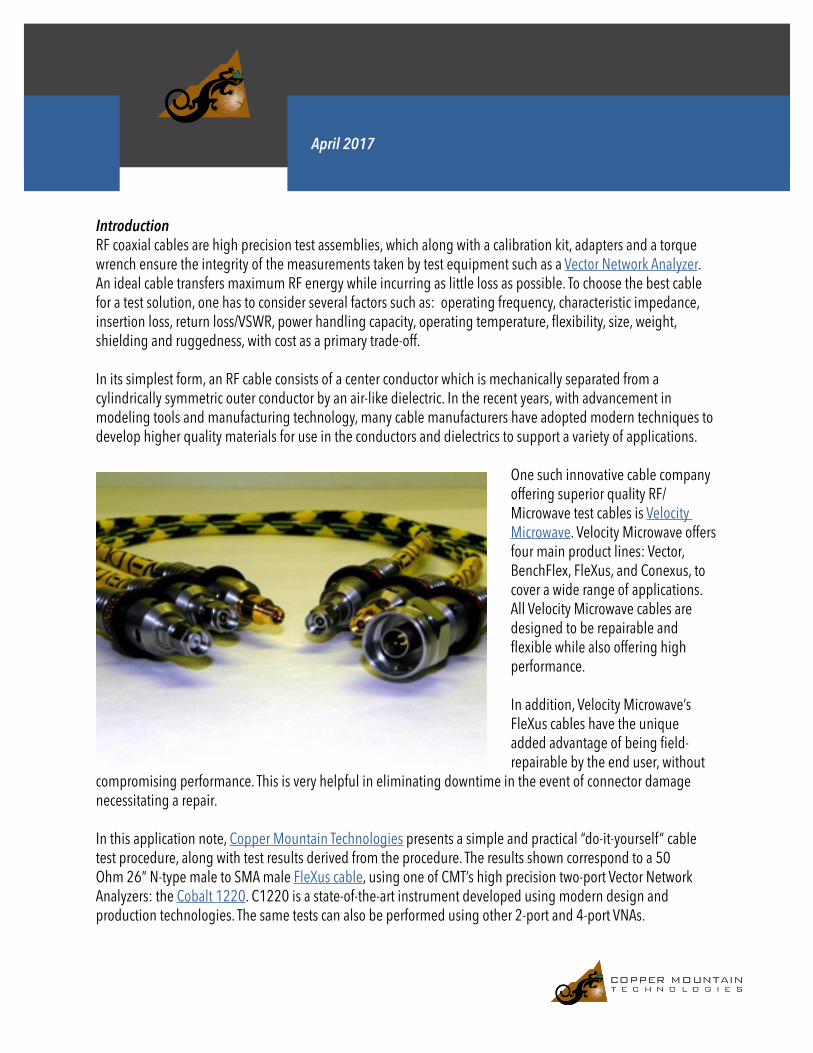
One such innovative cable company offering superior quality RF/Microwave test cables is Velocity Microwave. Velocity Microwave offers four main product lines: Vector, BenchFlex, FleXus, and Conexus, to cover a wide range of applications. All Velocity Microwave cables are designed to be repairable and flexible while also offering high performance.
In addition, Velocity Microwave’s FleXus cables have the unique added advantage of being field-repairable by the end user, without
compromising performance. This is very helpful in eliminating downtime in the event of connector damage necessitating a repair.
In this application note, Copper Mountain Technologies presents a simple and practical “do-it-yourself” cable test procedure, along with test results derived from the procedure. The results shown correspond to a 50 Ohm 26” N-type male to SMA male FleXus cable, using one of CMT’s high precision two-port Vector Network Analyzers: the Cobalt 1220. C1220 is a state-of-the-art instrument developed using modern design and production technologies. The same tests can also be performed using other 2-port and 4-port VNAs.

Test Method
The test method is organized into three stages: connector verification, electrical test, and stability test.
1. Connector verification
First, visually check to see if the cable’s connector is contaminated by dust or any foreign object. If contaminated, measurements can be affected, so it is necessary to clean the connectors. We recommend the following procedures for cleaning:
- Clean the connector surfaces with a lint-free cotton swab dampened by isopropyl alcohol.- Dry the connector with low-pressure compressed air.- Repeat the process if the connector is still contaminated.
Next, check the connectors for any mechanical damage. If there is no damage, then proceed with pin depth measurements of the connectors. For pin depth measurement, you will require a good connector gage of the appropriate gender and type. Another innovative product line from Velocity Microwave is connector gages that are capable of measuring both male and female connectors with a single gage. The connectors are considered to be “pass”, if the pin depth measured by the gage is within the acceptable range of the IEEE 287-2007 standard.
During examination, if the pin depth appears to be out of specification, or if the pin is mechanically damaged, then the cable needs to be repaired at a manufacturer-recommended service center. In the particular case of Velocity Microwave’s FLeXus test cables, then you can easily repair it yourself by following the procedure in this video.

2. Basic electrical test
This test assesses the cable’s insertion loss (attenuation), and the return loss (VSWR), by comparing the results obtained with the specifications in the cable’s datasheet.
To begin the test, first perform a full two-port SOLR calibration using a good calibration kit, adapters, and preferably a different cable (other than the one being tested). To achieve accurate results, it is recommended to configure the C1220 VNA settings as follows: Start -> VNA’s lowest frequency; Stop -> Cable’s maximum frequency; Sweep -> Linear; IFBW -> 1kHz; Power -> -5 dBm.
Connect the test cable as the DUT, and measure S11 VSWR and S21 Log Mag. Make use of markers to identify the max and min peaks of the traces. Compare the values obtained with the specifications of the cable.
The test is considered “passed” if the measured values are within the specified ranges for the cable.
In an ideal case, the VSWR would be close to 1.00, and the insertion loss would be approach 0 dB. However, this would correspond to a perfect cable, and is highly unrealistic. The measurements displayed below are of a sample FleXus cable, showing a maximum VSWR and insertion loss of 1.19 dB and 1.43 dB respectively.
Test setup of the cable and the C1220
Connector hub extracted from the cable during repair
3. Stability test
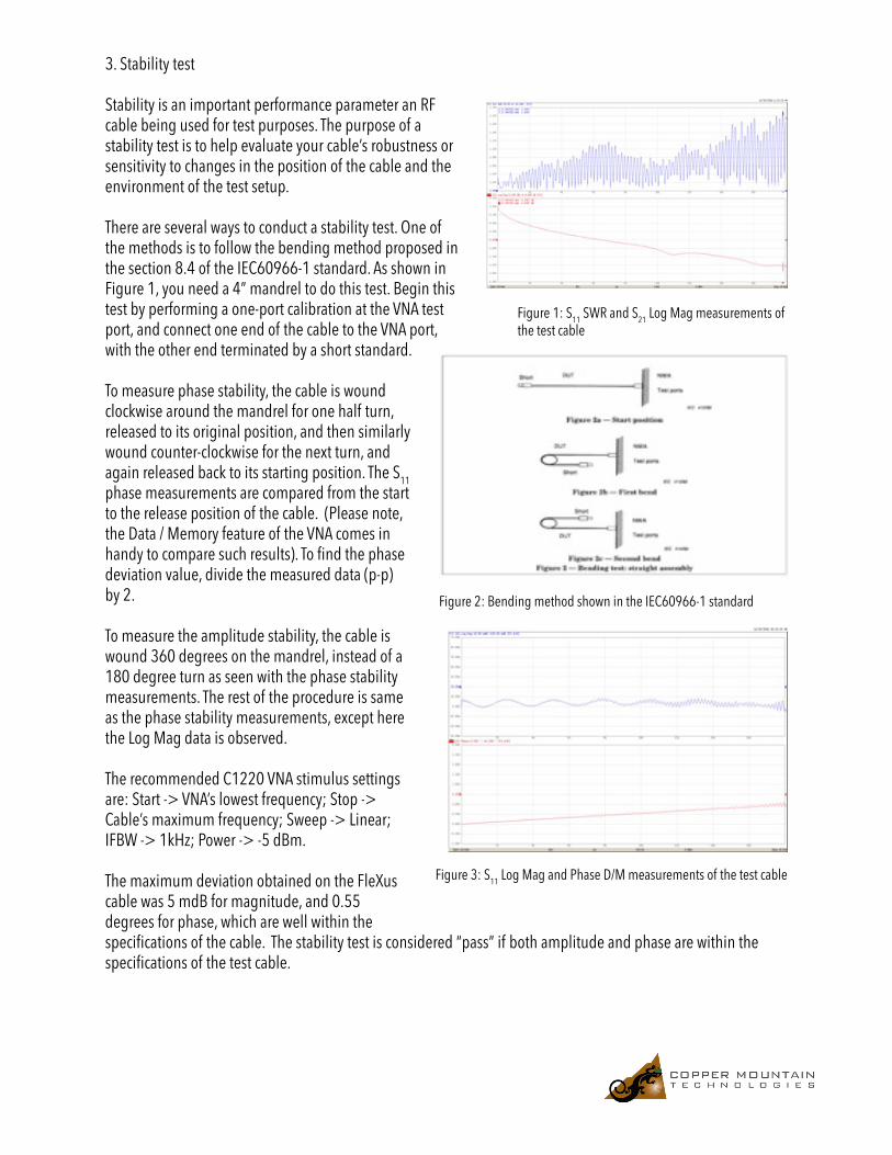
Stability is an important performance parameter an RF cable being used for test purposes. The purpose of a stability test is to help evaluate your cable’s robustness or sensitivity to changes in the position of the cable and the environment of the test setup.
There are several ways to conduct a stability test. One of the methods is to follow the bending method proposed in the section 8.4 of the IEC60966-1 standard. As shown in Figure 1, you need a 4” mandrel to do this test. Begin this test by performing a one-port calibration at the VNA test port, and connect one end of the cable to the VNA port, with the other end terminated by a short standard.
To measure phase stability, the cable is wound clockwise around the mandrel for one half turn, released to its original position, and then similarly wound counter-clockwise for the next turn, and again released back to its starting position. The S11 phase measurements are compared from the start to the release position of the cable. (Please note, the Data / Memory feature of the VNA comes in handy to compare such results). To find the phase deviation value, divide the measured data (p-p) by 2.
To measure the amplitude stability, the cable is wound 360 degrees on the mandrel, instead of a 180 degree turn as seen with the phase stability measurements. The rest of the procedure is same as the phase stability measurements, except here the Log Mag data is observed.
The recommended C1220 VNA stimulus settings are: Start -> VNA’s lowest frequency; Stop -> Cable’s maximum frequency; Sweep -> Linear; IFBW -> 1kHz; Power -> -5 dBm.
The maximum deviation obtained on the FleXus cable was 5 mdB for magnitude, and 0.55 degrees for phase, which are well within the specifications of the cable. The stability test is considered “pass” if both amplitude and phase are within the specifications of the test cable.
Figure 2: Bending method shown in the IEC60966-1 standard
Figure 1: S11 SWR and S21 Log Mag measurements of the test cable
Figure 3: S11 Log Mag and Phase D/M measurements of the test cable

Copper Mountain Technologiescoppermountaintech.com
US Office: +1.317.222.5400 | Singapore Office: +65.63.23.6546
Other Stability Tests
There are many other ways to perform stability tests of a cable. Some of them are drift test, longitudinal pressure test, and waver test. The initial setup procedure remains the same as the previous bending stability test (perform one-port calibration at the VNA port, connect one end of the cable to the VNA, and terminate the unused end by a short standard). However, you would not require a mandrel for these tests. Please begin the test by performing Data / Memory operation.
Drift Test: Hold the cable in wound status for a period of two minutes. Compare the drift seen with the stability limits.
Longitudinal Pressure Test: Apply mild longitudinal pressure along the axis of the cable until it is slightly bent, and release back to its original position. Compare the deviation seen with the stability limits.