high-rise buildings: h-01 - orange county fire authority · high-rise buildings: h-01 january 1,...
TRANSCRIPT

Orange County Fire Authority Community Risk Reduction
1 Fire Authority Road, Building A, Irvine, CA. 92602 www.ocfa.org 714-573-6100
High-Rise Buildings
Guideline H-01
Serving the Cities of Aliso Viejo • Buena Park • Cypress • Dana Point • Irvine • Laguna Hills • Laguna Niguel • Laguna Woods • Lake Forest •
La Palma • Los Alamitos • Mission Viejo • Placentia • Rancho Santa Margarita • San Clemente • San Juan Capistrano • Seal Beach • Santa
Ana • Stanton • Tustin • Villa Park • Westminster • Yorba Linda • and Unincorporated Areas of Orange County
High-Rise Buildings: H-01 January 1, 2017
2
High-Rise Buildings
PURPOSE This document is intended to provide developers, building owners, property managers, and
businesses with a comprehensive outline of the requirements for high-rise buildings as they
pertain to plan submittal, inspection, emergency pre-fire planning, and maintenance of high-
rise buildings.
SCOPE This document has been broken down into 4 distinct sections:
1. Section I – Plan Review: This section provides a comprehensive outline of fire code
requirements necessary for high-rise design.
2. Section II – Construction: This section provides the Orange County Fire Authority
(OCFA) inspection and communication process that helps ensure the project manager
is informed of and the steps necessary to allow OCFA staff to verify project compliance
during the construction process.
3. Section III – Emergency Incident Pre-Plan (subject to modification): To provide
property management teams and OCFA emergency responders with a guideline to
assist in creating an emergency pre-plan document of the building’s life safety systems
for utilization prior to and during an incident.
4. Section IV – Existing Buildings (currently under revision): Buildings, facilities, or
conditions which were constructed or officially authorized prior to the adoption of the
current code shall be maintained in accordance with the code they were constructed
under. Alterations, repairs, additions, and changes of occupancy to existing structures
shall comply with the provisions for alterations, repairs, additions, and changes of
occupancy in accordance with the requirements of the code for new construction (see
part I – Plan Review).
High-Rise Buildings: H-01 January 1, 2017
3
New High-Rise Buildings
Section I – Plan Review
PURPOSE This section describes the submittal requirements for high-rise buildings (HRB) which are
buildings where the highest occupied floor is more than 75 feet above the lowest floor level
having building access.
SCOPE This guideline provides the requirements for all HRB within the jurisdiction of OCFA.
Definitions: For the purposes of this guideline, certain terms are as follows:
CBC: 2016 California Building Code
CFC: 2016 California Fire Code
High-Rise Building or Structure: A building where the highest occupied floor is more than 75 feet above the lowest floor level that provides access to the interior of the building.
Fire Command Center (FCC): The principal attended or unattended location where the status of the detection, alarm communications and control systems is displayed, and from which the system(s) can be manually controlled.
Fire Control Room: See Fire Command Center
NFPA 13: 2016 Edition of the National Fire Protection Association 13: Standard for the installation of Sprinkler Systems.
NFPA 14: 2013 Edition of the National Fire Protection Association 14: Standard for the installation of Standpipe, Private Hydrant, and Hose Systems
NFPA 20: 2016 Edition of the National Fire Protection Association 20: Standard for Stationary Pumps for Fire Protection.
NFPA 22: 2013 Edition of the National Fire Protection Association 22: Standard for Water Tanks for Private Fire Protection.
NFPA 24: 2016 Edition of the National Fire Protection Association 24: Standard for the installation of Private Fire Service Mains and Their Appurtenances.
NFPA 72: 2016 Edition of the National Fire Protection Association 72: National Fire Alarm Code.
Occupiable Space: A room or enclosed space designed for human occupancy in which individuals congregate for amusement, educational or similar purposes or in which occupants are engaged in labor and which is equipped with the means of egress and light and ventilation facilities meeting the requirements of the CBC.
Penthouse: An enclosed, unoccupied structure above the roof of a building, other than a tank, tower, spire, dome, cupola or bulkhead, occupying not more than one-third of the roof area.

High-Rise Buildings: H-01 January 1, 2017
4
PLAN SUBMITTAL REQUIREMENTS 1. General Information: All new plan submittals and revisions will consist of 2 plan copies
and 1 electronic copy. All electronic formats will be accepted and may be submitted on
CD, DVD, or memory stick. Plans will need the following information and items:
A. Complete address of the project, including the tract and lot numbers
B. Architect name, address and phone number with a wet signature
C. Occupancy classification(s)
D. Type of construction
E. Total square footage
F. Number of floors
G. Regulating codes and their edition, e.g. 2016 CBC, 2016 CFC, etc.
H. Deferred submittals, e.g. fire sprinklers, fire alarm, etc.
I. Architectural, mechanical, plumbing, and electrical sheets
J. Door schedule that identifies hardware and fire resistive ratings
K. OCFA architectural notes, which can be located at www.ocfa.org under the Planning
and Development section in Fire Prevention
2. Specific Requirements:
Fire Department Access: Basic fire department access and hydrant requirements can
be found in OCFA guideline B-09. However, tactics for emergency response at high-rise
buildings focus more on aerial suppression and interior attack via the stairwells as
opposed to ground-level operations. In light of this, portions of the high-rise building’s
perimeter that do not contain building entry points may be located up to 300 feet from a
fire lane. In addition, the site design for high-rise buildings shall incorporate the specific
provisions listed below to facilitate aerial operations and roof access. Where unique site
or building conditions or restrictions prohibit compliance with these access and hydrant
provisions, the fire code official may modify or exempt individual provisions provided
that an acceptable level of alternative access, water availability, and safety is provided.
A. Vehicle laddering and staging areas:
1) A minimum of 2 laddering areas shall be provided for a high-rise building. The
laddering areas shall meet the criteria in sections B, C, D.1 through D.5, and E.3.
Buildings meeting the exception in D.1 or D.2 shall meet the criteria in B.2
through B.4, D.3 and D.5.
2) A staging area shall be provided for the FDC serving a high-rise building. The
FDC staging area shall meet the criteria in sections B, D.3, D.4, D.6, E.1 and E.3.
3) A staging area shall be provided for the fire command center. This staging area
shall meet the criteria in sections B, D.3, D.4, and D.7.
B. Laddering/Staging area design:
1) Laddering and FDC staging areas shall be rectangular with a length of at least 50
feet and a width of at least 16 feet; for buildings higher than 120’, the laddering

High-Rise Buildings: H-01 January 1, 2017
5
C.2: Laddering area X provides ladder access to two façades;
laddering area Y provides access to one façade.
X Y
area shall be at least 75 feet long. The staging area for the fire command center
shall be at least 50 feet by 10 feet.
2) Laddering/staging areas and fire lane leading to them shall be a permanent,
hard-surfaced material such as concrete, asphalt, or decorative pavers.
3) Laddering/staging areas are art of the fire lane and shall meet all standard fire
lane criteria. They shall not be used for any purpose that may potentially delay or
hinder emergency response by the fire department including, but not limited to:
parking, loading/unloading zone, waiting/drop-off area, valet services, or other
similar activities.
4) Laddering/staging areas shall be flat and provide with only enough slope/cross-
slope to facilitate drainage (~2%).
C. Location of laddering areas:
1. Laddering areas shall be located near opposing corners of the high-rise building
or near adjacent corners of one or more of the longest sides of the building in a
manner that optimizes access to the building façades and roof areas.
2. At least one laddering area shall provide
ladder access to two adjoining façades of
the structure.
3. Where a high-rise structure has multiple
roof levels that are not accessible from
each other, all such independent roof areas
shall be served by at least one laddering
area.
Exception: roof levels
higher than 90’ to the top
of the parapet or railing.
D. Laddering/Staging area setbacks:
1) For buildings no more than 90 feet high, as measured from the fire lane to the top
of the roof parapet or railing, laddering areas shall be provided 20 feet from the
façade as measured from the nearest edge of the laddering area.
Exception: When approved by the fire code official, designated laddering
areas are not required provided that the nearest edge of the fire lane is
located 20 feet from the structure along the entire length of at least 2 sides
C.1: Laddering areas at opposing corners. C.1: Laddering areas at adjacent corners of
the longest side of the building.

High-Rise Buildings: H-01 January 1, 2017
6
of the building, 1 of which is the longest side of the structure, or along at
least 50% of the perimeter of the structure, whichever is greater. An
unobstructed minimum 26 foot wide fire lane shall be provided; parking
and other obstructions shall not intrude into this clear width.
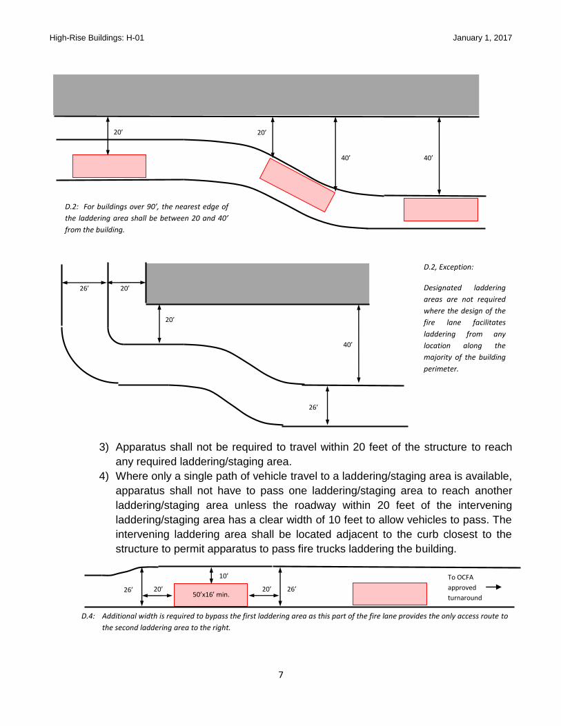
2) For buildings over 90 feet, the laddering areas shall be no less than 20 and no
more than 40 feet from the façade.
Exception: When approved by the fire code offici8al, designated laddering
areas are not required provided that the nearest edge of the fire lane is
located between 20 and 40 feet from the structure along the entire length
of at least 2 sides of the building, 1 of which is the longest side of the
structure, or for at least 50% of the perimeter of the structure, whichever is
greater. An unobstructed minimum 26 foot wide fire lane shall be provided;
parking and other obstructions shall not intrude into this clear width.
D.1: For buildings up to 90’ tall, the nearest edge of the laddering area shall be 20’ from the building.
20’ 20’
20’
16’
High-Rise Buildings: H-01 January 1, 2017
7
.
3) Apparatus shall not be required to travel within 20 feet of the structure to reach
any required laddering/staging area.
4) Where only a single path of vehicle travel to a laddering/staging area is available,
apparatus shall not have to pass one laddering/staging area to reach another
laddering/staging area unless the roadway within 20 feet of the intervening
laddering/staging area has a clear width of 10 feet to allow vehicles to pass. The
intervening laddering area shall be located adjacent to the curb closest to the
structure to permit apparatus to pass fire trucks laddering the building.
20’
40’
20’
40’
D.2, Exception:
Designated laddering
areas are not required
where the design of the
fire lane facilitates
laddering from any
location along the
majority of the building
perimeter.
20’
40’
20’
26’
26’
To OCFA
approved
turnaround
D.2: For buildings over 90’, the nearest edge of
the laddering area shall be between 20 and 40’
from the building.
26’ 26’ 20’ 20’ 50’x16’ min.
D.4: Additional width is required to bypass the first laddering area as this part of the fire lane provides the only access route to
the second laddering area to the right.
10’
High-Rise Buildings: H-01 January 1, 2017
8
5) Vegetation and other potential obstructions in the area between the building and
any portion of the fire department access roadway within 40 feet from the
structure shall not impede laddering operations and shall be restricted to 20 feet
in height at maturity.
6) Where the dimensions and topography of the site permit, the FDC staging area
shall be located at least 40 feet from the building and within 100 feet of the FDC.
When it is necessary to place it closer than 40 feet, it shall be located in such a
way as to minimize the potential for exposure to falling debris and heat/flame
impingement, such as adjacent to a wall without windows or other openings or
diagonally from a corner of the building.
7) A staging area shall be provided at least 20 but not more than 50 feet from the
fire command center in a position that is clearly visible from the door providing
access to that space.
E. Water:
1) Where the dimensions and topography of the site permit, the FDC and hydrant
serving it shall be located at least 40 feet from the building. They may be located
closer provided that they are located where exposure to falling debris or direct
flame impingement is minimized.
2) At least half, but not less than 2, of the hydrants required by CFC Appendix C to
serve the high-rise building shall be located at least 40 feet from the structure.
Where the dimensions and topography of the site do not permit this and with
approval of OCFA, they may be placed closer if they are in a location where
exposure to falling debris or direct flame impingement is minimized, such as a
wall without windows or other openings or diagonally from the corner of the
building.
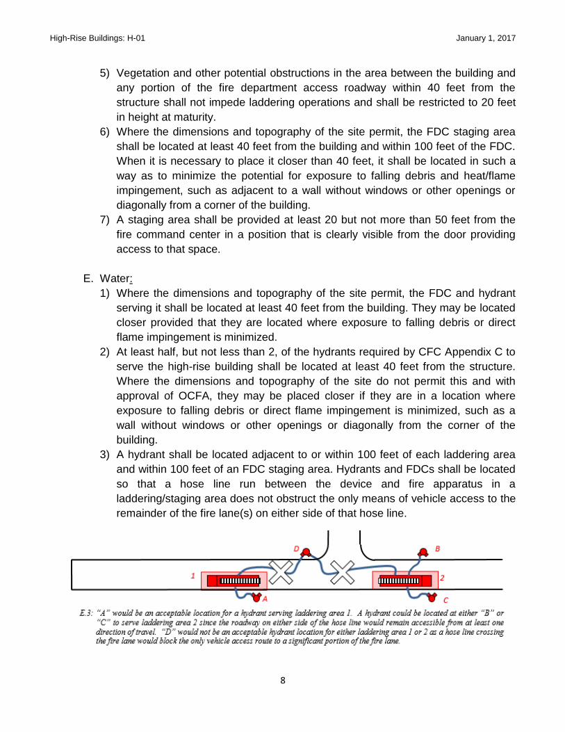
3) A hydrant shall be located adjacent to or within 100 feet of each laddering area
and within 100 feet of an FDC staging area. Hydrants and FDCs shall be located
so that a hose line run between the device and fire apparatus in a
laddering/staging area does not obstruct the only means of vehicle access to the
remainder of the fire lane(s) on either side of that hose line.

High-Rise Buildings: H-01 January 1, 2017
9
Fire Command Center (FCC): A FCC is required and shall be separated from the
building by a 1 hour fire barrier constructed in accordance with CBC Chapter 7. The
FCC shall be located so that it is accessible directly from the exterior door adjacent to
the fire department access roadway. The size of the room shall be a minimum of 200
square feet with the minimum dimensions of 10 feet. The FCC shall contain the
following equipment at a minimum:
A. Emergency voice/alarm communications
B. Fire alarm control panel (FACP)
C. Fire alarm/detection system annunciator unit
D. Elevator annunciator showing location and status
E. Status indicators and controls for air handling systems
F. Smoke control panel
G. Sprinkler valve and water-flow detector display panel
H. Emergency and standby power status indicators
I. Generator status panel with manual start and transfer features
J. Fire pump status panel
K. Controls for unlocking all stairway doors simultaneously
L. One work table (3’ x 5’) with 2 folding chairs
M. Knox key locker
N. Battery powered emergency lighting device (bug eyes)
O. Emergency contact information (building engineer, maintenance, property
management, security, alarm company, elevator company, major tenants point of
contact)
P. Schematic building plans in clearly labeled approved containers, indicating the
typical floor plan and detailing the building core, fire resistive separations, exit
facilities, on-site water supply, fire protection systems, firefighting equipment, and
fire department access.
Q. The entry door shall be provided with a Schlage lock with a “C” cylinder openable
with an OCFA master key. Once it has been installed, a licensed locksmith shall key
the cylinder. The locksmith shall contact OCFA fire prevention staff for the keying
sequence.
The panels/equipment shall be arranged on the wall in the following order starting left of
the entry door and proceeding in a clockwise direction.
A. Knox box
B. Controls for unlocking all stairway doors
C. Fire alarm annunciator (graphic display)
D. Fire alarm control panel (FACP)

High-Rise Buildings: H-01 January 1, 2017
10
E. Voice evacuation panel
F. Elevator status panel
G. Emergency and standby power status
H. Generator status panel
I. Fire pump status panel
J. Smoke control panel
K. Air handling unit status panel
L. Emergency contact information adjacent to telephone
Emergency Responder Radio Coverage System: 800 MHZ radio coverage shall be
provided in the building. The owner is responsible to retain a FCC-certified technician
who will test and certify the system before an issuance of a Certification of Occupancy.
Fire Alarm System: HRBs shall be provided with an approved automatic fire alarm
system meeting the requirements of 2016 CBC, 2016 CFC and 2016 NFPA 72. The
alarm plans may be submitted separately from other submittals. Prior to submitting the
alarm plans to OCFA, they shall be reviewed by the smoke control design engineer for
compliance of the smoke control design. The design engineer shall provide a letter
indicating compliance with the Smoke Control Rational Analysis.
Sequence of Operation:
1. General Alarm: Activation of a water flow switch, manual fire alarm box (if
any), smoke detector, or other fire protection or extinguishing system shall
activate the following:
a) Activation of all audible/visual devices and automatic voice evacuation on
the floor above, floor below, and the floor the initiating device is located
b) Activation of the stair pressurization fans
c) Activation of the smoke control system (if active system is provided) for
the floor involved, the floor above, and the floor below the floor involved
d) Stairwell doors to unlock (as applicable)
e) Release of all door hold open devices
f) Shut down heating ventilation air conditioning (HVAC) system
g) Closure of all fire and smoke dampers
h) Alarm to display on the FACP
i) Alarm to display on the graphic annunciator panel
j) Alarm signal to be sent to the central station
2. Elevator Recall: Smoke/heat detector activation in any elevator lobby,
elevator machine room, or elevator shaft shall recall to an alternate floor
approved by OCFA. Elevator shutdown is a separate function from elevator
recall that will need to occur only after completion of elevator recall. The

High-Rise Buildings: H-01 January 1, 2017
11
elevator shut down shall be initiated upon activation of a heat detector or
waterflow initiating device.
3. Duct Detectors: Activation of HVAC smoke detectors shall initiate the
following:
1. Shut down associated air handler system
2. Release all door hold open devices
3. Close all smoke dampers
4. Shows supervisory alarm on the FACP
5. Show supervisory alarm type on the graphic annunciator panel
6. Send supervisory alarm signal to the central station
Smoke Detectors: Smoke detectors shall be provided in the following locations:
A. Elevator machine rooms
B. Elevator lobbies
C. Telephone equipment rooms when not provided with sprinklers
D. Air handler systems with ≥ 2,000 CFM
1. In the main return air
2. Exhaust air plenum
3. At each connection to a vertical duct or riser serving 2 or more stories from a
return air duct or plenum of an air conditioning system
Audible Alarm & Voice Evacuation System: Activation of the audible fire alarm and
voice evacuation system shall be as follows:
A. Cycle: 3 slow-whoop tones (temporal pattern), electrically generated, followed by a
taped voice message.
B. The above cycle shall continue to sound until manually terminated by fire
department personnel. If the voice message fails to operate, the temporal pattern
shall continue to sound until terminated.
C. Unless an alternative message is approved by the OCFA, the voice message
recording shall state, “Attention, attention: An emergency has been reported in the
building. Please leave the building immediately through the marked exits. Do not use
the elevators, use only the exit stairwells.”
D. Speakers shall be provided throughout the structure and set up in paging zones. At
a minimum, the paging zones shall consist of:
1. Elevator groups
2. Exit stairways
3. Each floor
4. Areas of refuge
E. The system shall have a “live voice message” feature that allows broadcasting of live
voice messages through the paging zones on a selective and all-call basis.
High-Rise Buildings: H-01 January 1, 2017
12
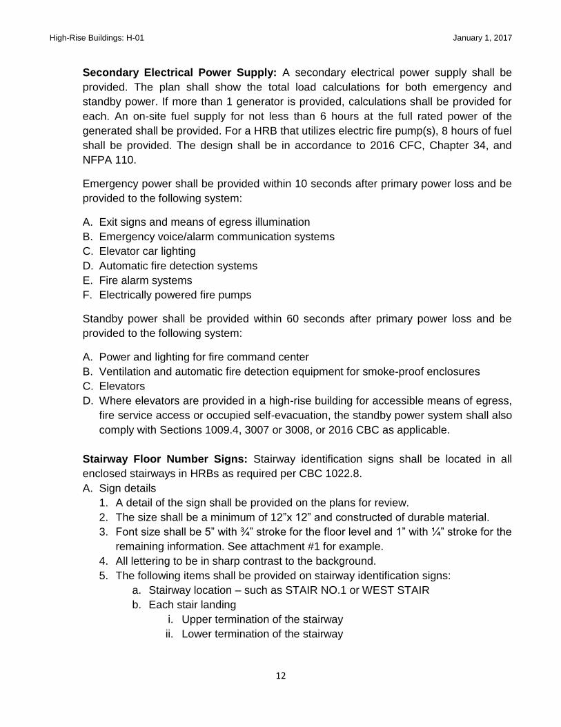
Secondary Electrical Power Supply: A secondary electrical power supply shall be
provided. The plan shall show the total load calculations for both emergency and
standby power. If more than 1 generator is provided, calculations shall be provided for
each. An on-site fuel supply for not less than 6 hours at the full rated power of the
generated shall be provided. For a HRB that utilizes electric fire pump(s), 8 hours of fuel
shall be provided. The design shall be in accordance to 2016 CFC, Chapter 34, and
NFPA 110.
Emergency power shall be provided within 10 seconds after primary power loss and be
provided to the following system:
A. Exit signs and means of egress illumination
B. Emergency voice/alarm communication systems
C. Elevator car lighting
D. Automatic fire detection systems
E. Fire alarm systems
F. Electrically powered fire pumps
Standby power shall be provided within 60 seconds after primary power loss and be
provided to the following system:
A. Power and lighting for fire command center
B. Ventilation and automatic fire detection equipment for smoke-proof enclosures
C. Elevators
D. Where elevators are provided in a high-rise building for accessible means of egress,
fire service access or occupied self-evacuation, the standby power system shall also
comply with Sections 1009.4, 3007 or 3008, or 2016 CBC as applicable.
Stairway Floor Number Signs: Stairway identification signs shall be located in all
enclosed stairways in HRBs as required per CBC 1022.8.
A. Sign details
1. A detail of the sign shall be provided on the plans for review.
2. The size shall be a minimum of 12”x 12” and constructed of durable material.
3. Font size shall be 5” with ¾” stroke for the floor level and 1” with ¼” stroke for the
remaining information. See attachment #1 for example.
4. All lettering to be in sharp contrast to the background.
5. The following items shall be provided on stairway identification signs:
a. Stairway location – such as STAIR NO.1 or WEST STAIR
b. Each stair landing
i. Upper termination of the stairway
ii. Lower termination of the stairway

High-Rise Buildings: H-01 January 1, 2017
13
c. The stairway upper terminus – such as ROOF ACCESS or NO ROOF
ACCESS
d. The stairway lower terminus – such as STAIR 3 ROOF ACCESS 1
THROUGH 12
e. Floor level number
i. The mezzanine levels shall have the letter “M” preceding the floor
number
ii. Basement levels shall have the letter “B” preceding the floor
number
B. Sign location
1. The plan shall specify that the Stairway Identification signs shall be located at
every stairway landing in buildings 4 or more stories in height.
a. Specify all signs shall be posted at a height no greater than 60” above the
floor level
b. Tactile signage shall comply with the CBC 1022.8, 1117B.5.11
Evacuation Signs: Evacuation signs are required per Title 19 Section 3.09 and Health
and Safety Code Section 13220.
A. Sign Details
1. Provide a detail of the signs for each floor-level
2. Specify that all signs shall include the following features:
a. Minimum lettering size 3/16 inch non decorative lettering
b. All lettering shall be in sharp contrast to the background
c. Constructed of durable material
d. Emergency exit routes, and map legend, shall include:
i. The pathway of the means of egress that indicates the evacuation
routes
ii. Exit doors

High-Rise Buildings: H-01 January 1, 2017
14
iii. Locations of manual fire alarm stations
iv. Schematic of manual fire alarm stations
v. Statements describing both audible and visual fire alarm systems
vi. Fire Department emergency telephone number 911
vii. Statement prohibiting the use of elevators in case of emergency
B. Sign Location
1. Identify the location of all evacuation signs for each floor. If the floor layout is
identical for multiple stories, the plan can be so indicated. A separate floor plan
for each subsequent identical floor-level will not be required.
2. Specify all signs shall be posed at a height no greater than 48” above the floor
level measured to the top of the sign.
3. The floor plan diagram on the evacuation sign shall be oriented directionally as it
is seen from the viewer’s perspective.
4. The following locations must be provided with an emergency evacuation sign:
a. All elevator landings
b. Every stairway landing (on the corridor side)
c. Immediately inside all public entrances to a public building
Fire Sprinkler System: All HRBs shall be protected by an automatic fire sprinkler
system. The sprinkler system design shall conform to NFPA 13, CBC Chapter 4 and
Chapter 9, and CFC Chapter 9. In the shell building, only quick response sprinklers
shall be used.
A fire pump shall be provided and rated to provide the demands of the sprinkler or
standpipe system whichever is greater. If the fire pump is electric, it shall be connected
to the emergency power system. The fire pump shall be designed and installed in
accordance to NFPA 20. In HRBs having an occupied floor more than 200 feet above
the lowest level of fire department vehicular access, 2 fire pumps shall be provided
(2016 CBC 403.3.2.1) and arranged in such a configuration to minimize the number of
pressure reducing valves or create multiple standpipe zones. Where a hose valve is
provided with a pressure reducing valve, the minimum size of the express drain shall be
3” with a capped groove outlet to test the pressure reducing valve.
The sprinkler system design shall be designed to minimize the use of pressure
regulating/reducing devices.
Standpipe System: The standpipe system shall be combined with the sprinkler system
risers and shall be installed according to CFC Chapter 9 and NFPA 14. The combined
systems shall be interconnected at the bottom between risers.
High-Rise Buildings: H-01 January 1, 2017
15
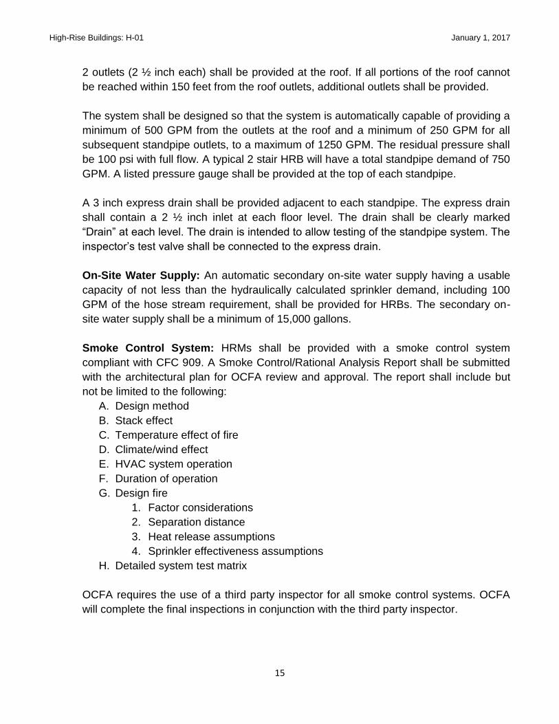
2 outlets (2 ½ inch each) shall be provided at the roof. If all portions of the roof cannot
be reached within 150 feet from the roof outlets, additional outlets shall be provided.
The system shall be designed so that the system is automatically capable of providing a
minimum of 500 GPM from the outlets at the roof and a minimum of 250 GPM for all
subsequent standpipe outlets, to a maximum of 1250 GPM. The residual pressure shall
be 100 psi with full flow. A typical 2 stair HRB will have a total standpipe demand of 750
GPM. A listed pressure gauge shall be provided at the top of each standpipe.
A 3 inch express drain shall be provided adjacent to each standpipe. The express drain
shall contain a 2 ½ inch inlet at each floor level. The drain shall be clearly marked
“Drain” at each level. The drain is intended to allow testing of the standpipe system. The
inspector’s test valve shall be connected to the express drain.
On-Site Water Supply: An automatic secondary on-site water supply having a usable
capacity of not less than the hydraulically calculated sprinkler demand, including 100
GPM of the hose stream requirement, shall be provided for HRBs. The secondary on-
site water supply shall be a minimum of 15,000 gallons.
Smoke Control System: HRMs shall be provided with a smoke control system
compliant with CFC 909. A Smoke Control/Rational Analysis Report shall be submitted
with the architectural plan for OCFA review and approval. The report shall include but
not be limited to the following:
A. Design method
B. Stack effect
C. Temperature effect of fire
D. Climate/wind effect
E. HVAC system operation
F. Duration of operation
G. Design fire
1. Factor considerations
2. Separation distance
3. Heat release assumptions
4. Sprinkler effectiveness assumptions
H. Detailed system test matrix
OCFA requires the use of a third party inspector for all smoke control systems. OCFA
will complete the final inspections in conjunction with the third party inspector.

High-Rise Buildings: H-01 January 1, 2017
16
High-Rise Buildings Section II - Construction
PURPOSE High rise construction sites are challenging to manage and inspect. This guideline is intended
to assure that minimum requirements are communicated and that communication between the
construction manager and the assigned OCFA inspectors are maintained throughout the
construction process. This will allow issues to be resolved in ways that are beneficial to the
building owner, developer, and OCFA.
SCOPE This guideline addresses minimum concerns and requirements for high rise construction sites
from an inspector and emergency response perspective. This document may not address all
issues that may be encountered at a high rise construction site. In those instances, the CFC
and assigned OCFA inspector should be consulted for guidance.
REQUIREMENTS 1. Pre-Construction: A meeting between the lead OCFA inspector, project manager and
job superintendent is strongly recommended to discuss all requirements including the
following:
A. Site phasing that may be necessary due to the complexity or size of the site,
business and/or construction needs. Phasing should be discussed during the review
process for the Fire Master Plan, so that planning for emergency access can be
addressed. A phasing plan may be required (see guideline B-09).
B. Inspection(s) scheduling will need to be adjusted based on phasing, number of
stories, number of devices, specialty systems, etc. A representative who has a basic
understanding of the information necessary to schedule the inspection should
contact the scheduling office in order to avoid any undue confusion and delays.
Additional fees may be due for phased or time intensive inspections.
C. Inspection Sequencing – A coordinated effort between automatic fire sprinkler,
alarm, specialty system contractors is needed to determine the order in which
inspection(s) should be completed. For example, the alarm system must be installed
and functioning prior to the testing of the smoke control system. Any questions
should be discussed with your inspector well in advance of the needed inspection
date.
D. Temporary Certificate of Occupancy (TCO) requirements vary from project to
project. At a minimum, fire and life safety systems and monitoring must be
operational and acceptance tested. OCFA will not recommend, or concur with a
TCO issuance from the building department until all testing and inspections
necessary for the high rise shell building has been completed. TCO and Certificate
High-Rise Buildings: H-01 January 1, 2017
17
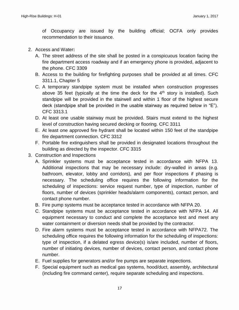
of Occupancy are issued by the building official; OCFA only provides
recommendation to their issuance.
2. Access and Water:
A. The street address of the site shall be posted in a conspicuous location facing the
fire department access roadway and if an emergency phone is provided, adjacent to
the phone. CFC 3309
B. Access to the building for firefighting purposes shall be provided at all times. CFC
3311.1, Chapter 5
C. A temporary standpipe system must be installed when construction progresses
above 35 feet (typically at the time the deck for the 4th story is installed). Such
standpipe will be provided in the stairwell and within 1 floor of the highest secure
deck (standpipe shall be provided in the usable stairway as required below in “E”).
CFC 3313.1
D. At least one usable stairway must be provided. Stairs must extend to the highest
level of construction having secured decking or flooring. CFC 3311
E. At least one approved fire hydrant shall be located within 150 feet of the standpipe
fire department connection. CFC 3312
F. Portable fire extinguishers shall be provided in designated locations throughout the
building as directed by the inspector. CFC 3315
3. Construction and Inspections
A. Sprinkler systems must be acceptance tested in accordance with NFPA 13.
Additional inspections that may be necessary include: dry-walled in areas (e.g.
bathroom, elevator, lobby and corridors), and per floor inspections if phasing is
necessary. The scheduling office requires the following information for the
scheduling of inspections: service request number, type of inspection, number of
floors, number of devices (sprinkler heads/alarm components), contact person, and
contact phone number.
B. Fire pump systems must be acceptance tested in accordance with NFPA 20.
C. Standpipe systems must be acceptance tested in accordance with NFPA 14. All
equipment necessary to conduct and complete the acceptance test and meet any
water containment or diversion needs shall be provided by the contractor.
D. Fire alarm systems must be acceptance tested in accordance with NFPA72. The
scheduling office requires the following information for the scheduling of inspections:
type of inspection, if a delated egress device(s) is/are included, number of floors,
number of initiating devices, number of devices, contact person, and contact phone
number.
E. Fuel supplies for generators and/or fire pumps are separate inspections.
F. Special equipment such as medical gas systems, hood/duct, assembly, architectural
(including fire command center), require separate scheduling and inspections.

High-Rise Buildings: H-01 January 1, 2017
18
G. Smoke control – a smoke control rational analysis must be reviewed and accepted
by the fire protection engineer from OCFA prior to inspection. OCFA requires the
use of a third party inspector for all smoke control systems. OCFA will complete the
final inspections in conjunction with the third party inspector.
H. Fire Master Site Plan final inspection for access, hydrants, fire lanes, signage, etc. is
required.
4. Miscellaneous
A. Combustible debris shall not be accumulated within buildings. Waste shall be
removed at the end of each work shift. CFC 3304.2
B. Motor equipment shall be located where exhausts do not discharge against
combustible material. Exhausts shall be piped to the outside of the building when
possible. Equipment shall not be refueled while in operation. Fuel for the equipment
shall be stored in an approved area outside of the building. CFC 3316
C. Heating devices must be of an approved type, kept away from combustible material,
and attended by competent personnel. CFC 3303
D. Smoking is prohibited within the building except in approved designated areas.
Suitable signs shall be posted. CFC 3304.1
E. Use and storage of flammable liquids shall comply with CFC 3404. Permits and/or
plans are required for the storage of more than 10 gallons of Class I flammable
liquids, or to install or operate tank vehicles, equipment, tanks, or fuel-dispensing
stations where flammable or combustible liquids are stored, dispensed, or used.
F. Asphalt kettles shall not be used inside or on the roof of a building. They shall not be
located within 20 feet of any combustible material, combustible building surface or
building opening and be equipped with a tight fitting cover, located and maintained
according to Section 303.CFC 3303.2
G. Cutting, welding or flame producing devices (hot work) are a significant fire risk and
are a major cause of fires during construction. Strict adherence to the fire code
requirements for hot work shall be followed
1) Hot work area shall not be located where flammable materials are being used or
stored without a fire resistive shield. CFC 3504.1.1
2) A minimum 2A:20BC extinguisher shall be provided within 30’ of any hot work on
the same floor. CFC 1408.5, 3504.2.6
3) A fire watch shall be provided and remain in place for a minimum of 30 minutes
after the hot work has concluded. CFC 3504.2
4) Complete pre-hot check as outlined in CFC 3504.3.1
Additional information that may be helpful regarding site construction, phasing, fees, and
temporary tanks can be found at www.ocfa.org.
High-Rise Buildings: H-01 January 1, 2017
19
High-Rise Buildings Section III – Emergency Incident
Pre-Plan (this section is under construction and subject to
modification)
PURPOSE To provide property management teams and OCFA emergency responders with a guideline to
assist in creating an emergency pre-plan document of the building’s life safety systems for
utilization prior to and during an incident.
COORDINATION The OCFA inspector will provide a copy of this document to the building representative during
building construction (at least 60 days prior to expected building occupancy). In cooperation
with OCFA operations department, the inspector will provide the name and phone number of
the designated OCFA fire captain who will actively participate with the building representative
in the development of the Emergency Incident Pre-Plan. The inspector will consult with the
designated fire captain prior to the OCFA project final to ensure that the developer’s portion of
the Emergency Incident Pre-Plan has been completed.
REQUIREMENTS Prior to OCFA concurrence for a release of a Certificate of Occupancy for any new high rise
structure, the fire inspector will coordinate with the building owner or their representative and
the fire captain to obtain specific information and documentation that will allow the
development of an Emergency Response Pre-Plan (ERP). While a majority of the ERP is best
developed by the property management team, some elements are more effective when
coordinated with OCFA operations personnel. This document outlines the responsibilities of
both parties.
Content Summary: The pre-plan will include 8 basic sections including:
1. *Section 1 Site Map
2. *Section 2 Face Page and Special Building Information
3. *Section 3 Floor Plans
4. *Section 4 Sprinkler Valve Locations
5. Section 5 Building Systems
6. *Section 6 Emergency Contacts
7. Section 7 Permits and Conditions
8. Section 8 Notes/Comments
High-Rise Buildings: H-01 January 1, 2017
20
Format:
Digitized Data
1. * The information contained in the Table of Contents (above), Sections 1-4 and Section
6 must be included on the CD.
2. Electronic drawing files to be provided in “.dwg” or “.dxf” and “.tif” or “.pdf” formats.
3. All information must be sized to allow the information to be clearly understood when
printed in an 8.5” x 11” or 11” x 17” formats.
4. Text shall be standardized in Arial font (6 point or larger).
5. The CD must be labeled with the project name, date, project address (e.g. 123 Main
Street), and City in which the project is located.
Hard Copy
1. All sections will be clearly divided numerically, tabbed, and section number with page
numbers on provided, in a standard 3 ring binder, red in color, with the words
“Emergency Pre-Plan” on both the cover and spine.
2. A minimum of 6 binders will be required for each building.
3. All 6 copies of the completed document must be retained in the Fire Control Room and
readily available for use by emergency response personnel (6 binders are needed for
the various operational teams that are formed during an incident and may be modified if
special circumstances warrant more copies).
Content Details:
Table of Contents (Responsibility – Applicant)
1. The Table of Contents will be a single page, clearly color-coded to identify each of the 8
sections contained in the document. A description of each section will be printed next to
each section title number (i.e. Section 1 – Site Map).
Section 1 – Site Map (Responsibility – Applicant and OCFA operations personnel)
This section shall include:
1. A vicinity map indicating cross streets, interior roads, and driveways. The building
footprints and general parking areas shall be indicated. Fire control features such as fire
hydrants, fire department connections and emergency control room locations must also
be noted. Any impedance to fire access shall also be noted, such as vertical or
horizontal obstructions.
2. Special conditions affecting access, such as landscaping, including turf blocking must
be noted. Where possible, the OCFA captain will utilize the information that may have
been previously provided to OCFA during the processing of the Fire Master Plan.

High-Rise Buildings: H-01 January 1, 2017
21
3. The building owner is responsible to further prepare the drawing to meet the specific
requirements contained within this section and any identified operational needs.
Section 2 – Face Page/General Information (Responsibility – Applicant and OCFA operations
personnel)
The Face Page shall include:
1. An artist’s rendering of the building including: address, building name, type of business
(office, residential, mixed use), fire control systems, occupancy load, construction type
(UBC descriptions), floors (number of floors above and below grade).
2. Information regarding special system, equipment or hazards. OCFA operations
personnel will define this information during construction walk-through and training
exercises and update the content accordingly.
Section 3 – Floor Plans (Responsibility – Applicant)
Floor plans shall include but not be limited to:
1. Show the basic footprint and plan of each floor with only the necessary detail to access,
locate and control fires, areas of refute, or provide medical assistance.
2. Show only as much interior wall detail as practical given the page restrictions, but
should display firewalls.
3. Each residential unit (if applicable) shall be identified by its address and/or unit number.
4. The building facility rooms shall be identified by their individual use, such as laundry,
electrical, mechanical, etc.
5. All floor plans shall use the standard OCFA pre-plan symbols (to be provided by the
OCFA fire captain) to indicate interior features that are important to firefighting
operations.
6. Every page of the floor plan section will have a “Floor Plan Level indicator” drawing in
the upper left corner. This drawing will show the floor location in relation to the entire
building.
Section 4 – Sprinkler Sectional Valves (Responsibility – Applicant)
This section will include:
1. A floor plan which indicates the location of sectional valves and the coverage area for
each valve. The valve coverage area is to be indicated by gray shading.
Section 5 – Building Systems (Responsibility – OCFA operations personnel)
This section will include all systems related to fire protection and life safety equipment within
the building. These systems may include but are not limited to:

High-Rise Buildings: H-01 January 1, 2017
22
Alarm systems Fire pumps Fire phones Generators
Air handling systems Elevators Communication systems
Smoke Control System
Chemical Storage Areas
Areas of Refuge
1. Include operating instructions, diagrams, photographs, and other pertinent information
that could assist firefighters in the rapid interpretation and use of building systems.
Section 6 – Emergency Contacts (Responsibility – Applicant)
This section includes:
1. Emergency contact information: names, 24 hour phone numbers (can be broken into
day and evening numbers), is knowledgeable about the building, has the codes or keys
necessary for the building, and the authority to manage the building after hours.
Section 7 – Permits and Conditions (Responsibility –OCFA FPS (Fire Prevention Specialist)
This section will be left blank and will be used by the OCFA’s FPS (new construction or annual
team) to provide documentation of the permits, conditions, and/or limitations allowed within the
structure by the OCFA.
Section 8 – Notes/Comments (Responsibility –OCFA operations personnel)
This section is left blank and intended to be used at the time of an emergency incident for
operations personnel utilizing the plan to keep notes and comments. Blank white paper is
placed here.
Note: This guidance document includes selective samples of the content for Sections 1-
5 of a completed High Rise Emergency Pre-Plan to assist in developing information that
meets OCFA needs.

High-Rise Buildings: H-01 January 1, 2017
23
High-Rise Buildings Section IV – Annual Maintenance
(This section is currently under revision)