high security sound - adsworldwide · pava product range overview and references 4-5 sinaps diva /...
TRANSCRIPT

Catalogue 2009
Public Address - Voice Alarm - Commercial Audio - Intelligent Acoustic Solutions - Counter Intercom
Hig
h S
ecu
rity
So
un
d
http : //www.ateis-international.com

W h o a r e w e ?
Few companies have such a drive for innovative developments that their name automatically links to a particular market sector however, ATEÏS has become synonymous with high quality Voice Alarm and Public Address systems in the transportation sector across Europe. With governments currently putting extra resources into their country’s infrastructure and transportation systems in order to create a boost for their economies, ATEÏS finds itself in a unique position, as serving the transportation sector with audio and data networking is what we do best. With our own audio networking and data-routers, voice over IP solutions and our latest development, Intercom over IP, we are leading the industry!
The ATEÏS brand name is found on many prestigious Public Address and Voice Alarm installations throughout the world, such as Hong Kong Airport, Dubai Jumeirah Beach Hotel or SNCF France to name just a few.
At the heart of the company’s success sits a team of young engineers who are highly motivated to apply the latest technologies into our designs. With its operational heart in Switzerland and factories in France, Taiwan and China, and offices across the globe, ATEÏS has become a true multinational that is expanding faster than ever before.
ATEÏS serves three key audio sectors; Public Address and Voice Alarm, Commercial Audio and Intelligent Acoustic Solutions. The newest, Intelligent Acoustic Solutions, has already become an important sector for ATEÏS, with the introduction of steerable line arrays, the new Bass and Compact Arrays and our involvement in Electronic Acoustic Modeling systems.
The company’s ultimate goal is to meet the needs of our customers and to provide the best possible solutions to them. For ATEÏS, doing business is all about the relationship we build and maintain with our customers, and ensuring that your trust and partnership will turn into success, opportunities and satisfaction!
“Thank you for the opportunity and the privilege to be of service!”
Albert van der HoutInternational Sales & Marketing Manager
Lyon International airportBasel International airportLiege International airportUniversity Hospital GenevaParis subwayLausanne subwayMarseille Train stationValence Train stationJohanesburg CasinoTorino Palaoval Olympic stadiaDubai Snow CenterTurning torso Building (Sweden)Milan hospitalNestlé European HeadquarterDubaï Jumeirah Beach HotelLiverpool CathedralDubai Festival City shopping mallRoyal Festival Hall LondonZara shops (Spain + France)Carrefour shopping center (Bern)East TGV Railway stations - FranceMarseille Subway - FranceNice airport - FranceEuropean Parlement of BrusselsMoscow TV StationFrankfurt AirportDutch RailwaysAirport, Zürich
A few references
PAVA product range overview and references 4-5
SINAPS DIVA / DIVA8M 6
SINAPS COMPACT / IDA4 7
SINAPS M/XM / IDA4M - IDA4Ms / IDA4XM - IDA4XMs / IDA4SU 8-10
SINAPS SWITCHING and IDA4SU / IDA4SW - IDA4SWs 11
VOX@NET / Vox@net softserver - Vox@net control - Vox@net remote -Vox@net-In - Vox@net-Out 12-13
SINAPS with LAPG2 for networked applications / LAPG2 14
SINAPS SECURITY MICROPHONES / PSM8 - PSM-keypad - PSSDT - PSSKB - SHM1 - SPM1 - IDASEC 15
SINAPS MICROPHONES and ACCESSORIES / DIGIM1 - DIGIM4 - DIGIM8 - DIGIINT - PABFMP - PS24 - SONaes - EVAC-BOARD - IDA-INT 16
SECURITY AMPLIFIERS / SPA480 - SPA2060 - SPA2120 - SPA2240 17
D-CLASS POWER AMPLIFIER / DPA4120 18
NETWORKED PROGRAMMABLE DIGITAL AUDIO SYSTEM / LAPG2 19 - 23
FULLY PROGRAMMABLE AUDIO MATRIX / UAP88 24 - 25
STACKABLE FULLY PROGRAMMABLE AUDIO MATRIX WITH ENHANCED DSP POWER / UAPG2 26 - 28
VERTICAL LOUDSPEAKER ARRAY / SMARTVOX II® 29
LINE ARRAYS / MESSENGERG2® 30 - 31
STEEREBAL BASS-ARRAY DSP CONTROLLER 32
LOW CEILING HORN / LCH70T 33 - 34
FULL DUPLEX DIGITAL INTERCOM / MAGELLAN 35 - 36
FULL DUPLEX SPEAKER PHONE / MAGELLAN COMPACT 37
FULL DUPLEX SPEAKER PHONE / MAGELLAN VOCAL POINT 38
REFERENCES 39
PUBLIC ADDRESS - VOICE ALARM
COMMERCIAL AUDIO
INTELLIGENT ACOUSTIC SOLUTIONS
COUNTER INTERCOM
Index
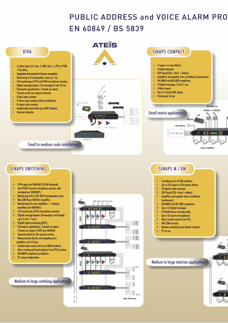
5 audio inputs (2 x line, 1x MIC/ line, 1 x PSS or PSM, 1 Fire Mic.).
Integrated and monitored Firemen microphone. Monitoring of 8 Loudspeaker zones (a+b). Full monitoring of PSS and PSM microphone consoles. Digital message players (16 messages) 4 min 22 sec. Parametric equalization: 3 bands on inputs, 7 bands on the two outputs channels. 8 logic input contacts. 9 alarm input contacts (with surveillance). 8 output relay contacts. Incident data record with up to 2047 incidents. Internal scheduler.
DIVA
4 PA inputs per IDA4SW/S (0 dB balanced). One PSSDT security microphone consoles with
touchpad per IDA4SW/S. Monitoring of 8 to 256 100 V Loudspeaker zones. Max 500 W per IDA4SU /amplifier. Monitoring of 4 zone amplifiers +1 backup
amplifiers per IDA4SW/S. Full monitoring of PSS microphone consoles. Digital message players (8 messages, total length
up to 2 min 11 sec.). Digital signal processing (DSP). Parametric equalization: 3 bands on inputs,
7 bands on outputs (1OUT per IDA4SU). Separate levels for the security sources. Measurements (levels and impedance) of amplifiers and LS lines. Incident data record with up to 2048 incidents. Music routing and level selection from PSS consoles. EN 60849 compliant surveillance. PC setup configuration.
SINAPS SWITCHING
Cascading up to 64 IDA modules. Up to 256 inputs to 256 outputs Matrix. 32 digital audio channels. DSP based (EQ+level+delays). Amplifiers and speaker lines surveillance
(continuous). EN 60849 and BS 5839 compliance. Up to 12 Digital messages. 4 Simultaneous messages play. Up to 32 security microphones. Music remote control from PSS. AGC (XM version). Remote controlling from Master location. PC set up.
SINAPS M / XM
5 Inputs x 4 zones Matrix. 4 Audio channels. DSP based (EQ+level +delays). Amplifiers and speaker lines surveillance (continuous). EN 60849 and BS 5839 compliance. 4 Digital messages, 2 min 11 sec. 4 Music inputs. Up to 2 security MIC inputs. Front panel set up.
SINAPS COMPACT
Small to medium-scale installations
Small matrix application
Medium to large switching application
Medium to large matrixes applications
PUBLIC ADDRESS and VOICE ALARM PRODUCT RANGEEN 60849 / BS 5839

Ethernet, TCP/IP, VLA compliant. adjustable audio data rate (MP3 compression). 1 sec. max. latency time. Up to 99 priority levels. Scheduler for automatic audio messages
brodcasting.
Up to 200 remote stations. Up to 99 control stations. Thousands of pre-recorded messages/
songs. Up to 10 simultaneous audio channels. Remote station status reporting global. Remote configuration of the Sinaps systems.
VOX@NET
TCP / IP Audio distribution system
AV 1500
R 1400
Up to 32 LAPs. Up to 12 zones per LAP. Up to 16 inputs per LAP. More than 16 microphones per LAP. 44 Digital PA channels. 4 Alarm channels. Free DSP architecture. Amplifiers and speaker lines surveillance (continious).
EN 60849 and BS 5839 compliance. 8 Digital messages per LAP rack. 4 Simultaneous messages play. Remote controlers (sources+levels). Presets. AGC. Remote contolling from Master location. PC set up. User friendly GUI.
Networked applications
LAP with SINAPS
PUBLIC ADDRESS and VOICE ALARM PRODUCT RANGEEN 60849 / BS 5839

B
PU
BL
IC A
DD
RE
SS
- V
OIC
E A
LA
RM
SINAPS DIVA
DIVA8M
5 audio inputs (2 x line, 1x MIC/ line, 1 x PSS or PSM, 1 Fire Mic.). Integrated and monitored Fireman microphone. Monitoring of 8 Loudspeaker zones (a+b). Full monitoring of PSS and PSM microphone consoles. Digital message player up to 45 min. Low and high pass filtering on inputs. Parametric equalization: 3 bands on inputs, 7 bands on the two outputs channels. 8 logic input contacts. 21 priority levels 4 user levels 9 alarm evacuation input contacts (with surveillance). 8 output relay contacts. Possibilities to export the event log Incident data record with up to 2047 incidents. 2 fault relays Internal scheduler.
MAIN PROPERTIES
The DIVA8M module unit houses: audio digital signal processing (DSP), a matrix, a digital message player, a fully monitored fireman microphone, amplifiers monitoring with switchover to backup amplifier and loudspeaker lines monitoring. It can process and route one PSSxxDT security microphone console or up to eight cascaded PSM paging microphones and two 0 dB audio inputs, plus one Mic/Line input, into 2 different channels (Music + Voice). Each input is fitted with volume controls and equalizers. All audio inputs feature contact and VOX activation (ideal when using the cordless microphone, for example). Up to 45 minutes of digital messages can be downloaded and recorded as WAV files directly from a computer into DIVA8M. Two messages can be played simultaneously in different zones. One of the messages can be used as a chime for the PSS microphone. Nine monitored alarm inputs making it possible to obtain the pre-programmed routings.Each DIVA module has eight output zones with a+b wiring. Each zone can be routed manually or automatically to one of the system’s audio channels (Music and Voice). The number of zones can be extended up to 128 zones with DIVA8Ms (Slave-module). The two Music channels can be switched ON/OFF in each zone separately. In case of Evacuation, the Music channel can be used as a second alarm channel.A DIVA system requires only one 2 channel amplifier (one for Music, one for Voice). The Music amplifier will act as a backup amplifier in case of a Voice amplifier failure. Each channel can handel up to 500 W of audio power (100 V).
From the front panels, the user can manually route the fireman microphone signal and three digital messages into the selected zones, adjust the audio level and switch (ON/OFF) the music in each zone separately. In case of evacuation, the zones attenuators are automatically bypassed.One output contact per zone (eight per unit) can be activated each time the zone is occupied with a source having a higher priority than the music (Alarm or microphone paging…).
As an EN 60849 security system, all DIVA components and peripherals are constantly monitored (without music interruption). All incidents are recorded into a data file which can be consulted on the DIVA display or on a PC. Also any
detected faults and alarm status are signalled by general fault and alarm output contacts. A local loudspeaker enables selective listening to all the sources and the system’s output signals.
The setup of DIVA is realised through a PC computer and the PCDIVA configuration software (Windows compatible). Access can be password-protected.The routing and the level of the music sources can be controlled directly from the PSS microphone.
All these features make DIVA the ideal system for shopping malls, hotels, restaurants, museums and many other public places.
Sma l l and Med ium I n s t a l l a t i on sDIVA
DIVA8M responds to public address requirements and Voice Alarm EN 60849/BS 5839 compliance for
small to medium installations.
B
PU
BL
IC A
DD
RE
SS
- V
OIC
E A
LA
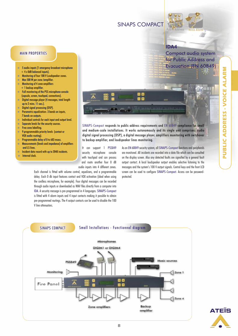
RM 5 audio inputs (1 emergency broadcast microphone
+ 4 x 0dB balanced inputs). Monitoring of four 100 V Loudspeaker zones. Max 500 W per zone /amplifier. Monitoring of 4 zone amplifiers
+ 1 backup amplifier. Full monitoring of the PSS microphone console
(capsule, screen, touchpad, connections). Digital message player (4 messages, total length
up to 2 mins. 11 secs.). Digital signal processing (DSP). Parametric equalization: 3 bands on inputs, 7 bands on outputs. Individual controls for each input and output level. Separate levels for the security sources. Free zone labelling. 9 programmable priority levels (contact or
VOX audio routing). Programmable delay of 0 to 683 msecs. Measurements (levels and impedance) of amplifiers
and LS lines. Incident data record with up to 2048 incidents. Internal clock.
SINAPS COMPACT
It can support 1 PSS849 security microphone console with touchpad and can process and route another four 0 dB
audio inputs into 4 different zones. Each channel is fitted with volume control, equalizers, and a programmable delay. Each 0 db input features contact and VOX activation (ideal when using the cordless microphone, for example). Four digital messages can be recorded through audio inputs or downloaded as WAV files directly from a computer into IDA. A security message is pre-programmed in 4 languages. SINAPS-Compact is fitted with 4 alarm inputs and 4 input contacts making it possible to obtain pre-programmed routings. The 4 output contacts can be used to disable the 100 V line attenuators.
As an EN 60849 security system, all SINAPS-Compact functions and peripherals are monitored. All incidents are recorded into a data file which can be consulted on the display screen. Also any detected faults are signalled by a general fault output contact. A local loudspeaker output enables selective listening to the messages and the system’s 100 V output signals. Control keys and the front LCD screen can be used to configure SINAPS-Compact. Access can be password-protected.
IDA4Compact audio system for Public Address and Evacuation (EN 60849)
MAIN PROPERTIES
Sma l l I n s t a l l a t i on s - Fun c t i onna l d i ag ramSINAPS COMPACT
SINAPS-Compact responds to public address requirements and EN 60849 compliance for small and medium-scale installations. It works autonomously and its single unit comprises: audio digital signal processing (DSP), a digital message player, amplifiers monitoring with switchover to backup amplifier, and loudspeaker lines monitoring.
B
PU
BL
IC A
DD
RE
SS
- V
OIC
E A
LA
RM
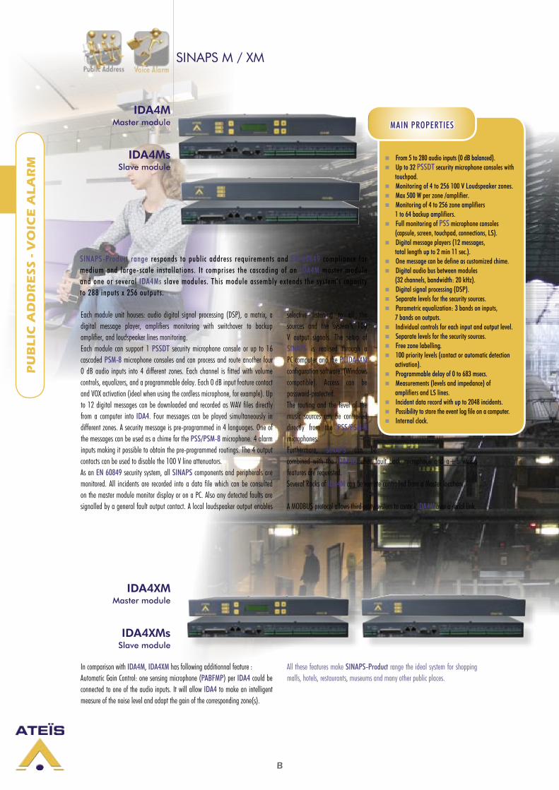
IDA4MsSlave module
SINAPS M / XM
IDA4MMaster module
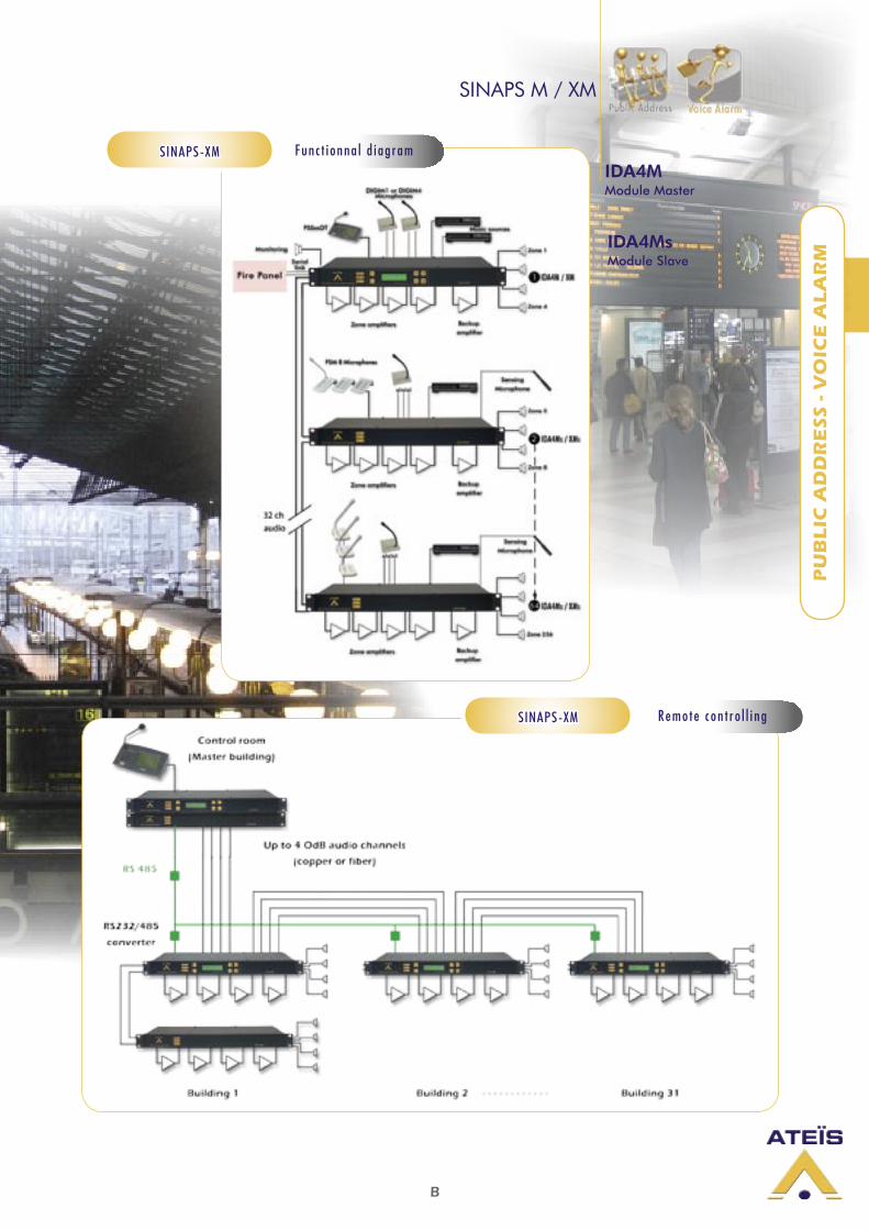
Each module unit houses: audio digital signal processing (DSP), a matrix, a digital message player, amplifiers monitoring with switchover to backup amplifier, and loudspeaker lines monitoring.Each module can support 1 PSSDT security microphone console or up to 16 cascaded PSM-8 microphone consoles and can process and route another four 0 dB audio inputs into 4 different zones. Each channel is fitted with volume controls, equalizers, and a programmable delay. Each 0 dB input feature contact and VOX activation (ideal when using the cordless microphone, for example). Up to 12 digital messages can be downloaded and recorded as WAV files directly from a computer into IDA4. Four messages can be played simultaneously in different zones. A security message is pre-programmed in 4 languages. One of the messages can be used as a chime for the PSS/PSM-8 microphone. 4 alarm inputs making it possible to obtain the pre-programmed routings. The 4 output contacts can be used to disable the 100 V line attenuators. As an EN 60849 security system, all SINAPS components and peripherals are monitored. All incidents are recorded into a data file which can be consulted on the master module monitor display or on a PC. Also any detected faults are signalled by a general fault output contact. A local loudspeaker output enables
selective listening to all the sources and the system’s 100 V output signals. The setup of SINAPS is realised through a PC computer and the PCIDA4XM configuration software. (Windows compatible). Access can be password-protected. The routing and the level of the music sources can be controlled directly from the PSS/PSM-8 microphones. Furthermore, SINAPS can be combined with the IDA4SU when fault back microphone and a+b wiring features are requested.Several Racks of IDA4M can be remote controlled from a Master location.
A MODBUS protocol allows third party system to control IDA4M over a serial link.
From 5 to 280 audio inputs (0 dB balanced). Up to 32 PSSDT security microphone consoles with touchpad. Monitoring of 4 to 256 100 V Loudspeaker zones. Max 500 W per zone /amplifier. Monitoring of 4 to 256 zone amplifiers 1 to 64 backup amplifiers. Full monitoring of PSS microphone consoles (capsule, screen, touchpad, connections, LS). Digital message players (12 messages, total length up to 2 min 11 sec.). One message can be define as customized chime. Digital audio bus between modules (32 channels, bandwidth: 20 kHz). Digital signal processing (DSP). Separate levels for the security sources. Parametric equalization: 3 bands on inputs, 7 bands on outputs. Individual controls for each input and output level. Separate levels for the security sources. Free zone labelling. 100 priority levels (contact or automatic detection activation). Programmable delay of 0 to 683 msecs. Measurements (levels and impedance) of amplifiers and LS lines. Incident data record with up to 2048 incidents. Possibility to store the event log file on a computer. Internal clock.
MAIN PROPERTIES
IDA4XMsSlave module
IDA4XMMaster module
In comparison with IDA4M, IDA4XM has following additionnal feature :Automatic Gain Control: one sensing microphone (PABFMP) per IDA4 could be connected to one of the audio inputs. It will allow IDA4 to make an intelligent measure of the noise level and adapt the gain of the corresponding zone(s).
All these features make SINAPS-Product range the ideal system for shopping malls, hotels, restaurants, museums and many other public places.
SINAPS-Product range responds to public address requirements and EN 60849 compliance for medium and large-scale installations. It comprises the cascading of an IDA4M master module and one or several IDA4Ms slave modules. This module assembly extends the system’s capacity to 288 inputs x 256 outputs.
B
PU
BL
IC A
DD
RE
SS
- V
OIC
E A
LA
RM
SINAPS M / XM
IDA4MModule Master
IDA4MsModule Slave
Fun c t i onna l d i ag ramSINAPS-XM
Remo te c on t r o l l i ngSINAPS-XM
B
PU
BL
IC A
DD
RE
SS
- V
OIC
E A
LA
RM
SINAPS M / XM
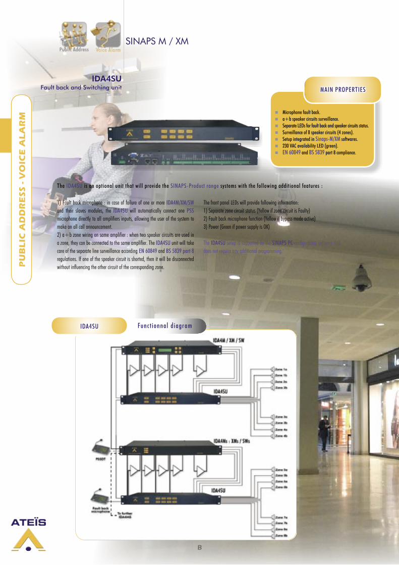
IDA4SUFault back and Switching unit
Microphone fault back. a+b speaker circuits surveillance. Separate LEDs for fault back and speaker circuits status. Surveillance of 8 speaker circuits (4 zones). Setup integrated in Sinaps-M/XM softwares. 230 VAC availability LED (green). EN 60849 and BS 5839 part 8 compliance.
MAIN PROPERTIES
1) Fault back microphone : in case of failure of one or more IDA4M/XM/SW and their slaves modules, the IDA4SU will automatically connect one PSS microphone directly to all amplifiers inputs, allowing the user of the system to make an all call announcement.2) a+b zone wiring on same amplifier : when two speaker circuits are used in a zone, they can be connected to the same amplifier. The IDA4SU unit will take care of the separate line surveillance according EN 60849 and BS 5839 part 8 regulations. If one of the speaker circuit is shorted, then it will be disconnected without influencing the other circuit of the corresponding zone.
The front panel LEDs will provide following information:1) Separate zone circuit status (Yellow if zone circuit is Faulty)2) Fault back microphone function (Yellow if bypass mode active)3) Power (Green if power supply is OK)
The IDA4SU setup is supported by the SINAPS PC configuration software and does not require any additional programming.
Fun c t i onna l d i ag ramIDA4SU
The IDA4SU is an optional unit that will provide the SINAPS-Product range systems with the following additional features :
B
PU
BL
IC A
DD
RE
SS
- V
OIC
E A
LA
RM 4 PA inputs per IDA4SW/s (0 dB balanced).
One PSSDT security microphone consoles with touchpad per IDA4SW/s. Monitoring of 8 to 256 100 V Loudspeaker zones. Max 500 W per IDA4SU /amplifier. Monitoring of 4 zone amplifiers + 1 backup amplifiers per IDA4SW/s. Full monitoring of PSS microphone consoles (capsule, screen, touchpad, connections, LS). Digital message players (8 messages, total length up to 2 min 11 sec.). Play back of up to 4 simultaneous digital messages. One message can be define as customized chime. Digital audio bus between IDA4SW/s modules (32 channels, bandwidth: 20 kHz). Digital signal processing (DSP). Parametric equalization: 3 bands on inputs, 7 bands on outputs (1 OUT per IDA4SU). Individual controls for each input and output level (1 OUT per IDA4SU). Separate levels for the security sources. Free zone labelling on PSS. 100 priority levels (contact or automatic detection activation). Programmable delay of 0 to 683 msecs per Output. Measurements (levels and impedance) of amplifiers and LS lines. Incident data record with up to 2048 incidents. Possibility to store the event log file on a computer. Internal clock. Music routing and level selection from PSS consoles. Monitoring loudspeaker output. Remote controlling of Slave racks from a Master location. EN 60849 compliant surveillance. PC setup configuration.
SINAPS SWITCHING and IDA4SU
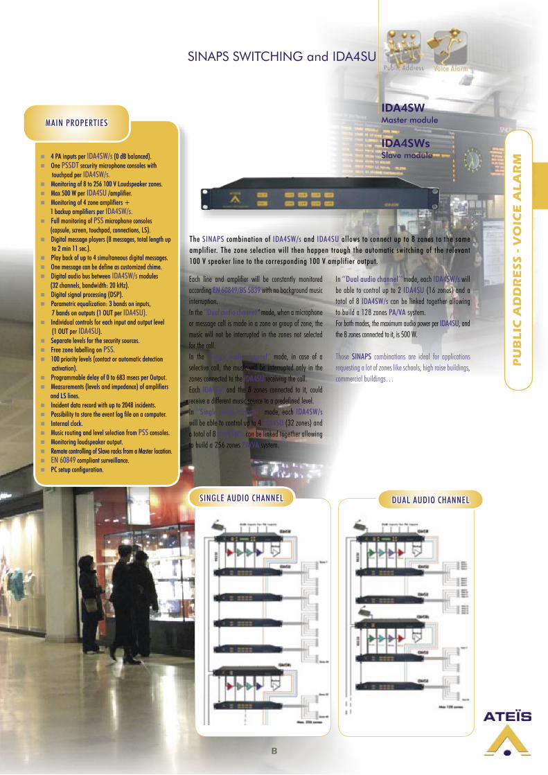
Each line and amplifier will be constantly monitored according EN 60849/BS 5839 with no background music interruption.In the ‘’Dual audio channel’’ mode, when a microphone or message call is made in a zone or group of zone, the music will not be interrupted in the zones not selected for the call.In the ‘’Single audio channel’’ mode, in case of a selective call, the music will be interrupted only in the zones connected to the IDA4SU receiving the call.Each IDA4SU, and the 8 zones connected to it, could receive a different music source to a predefined level.In ‘’Single audio channel’’ mode, each IDA4SW/s will be able to control up to 4 IDA4SU (32 zones) and a total of 8 IDA4SW/s can be linked together allowing to build a 256 zones PA/VA system.
In ‘’Dual audio channel’’ mode, each IDA4SW/s will be able to control up to 2 IDA4SU (16 zones) and a total of 8 IDA4SW/s can be linked together allowing to build a 128 zones PA/VA system.For both modes, the maximum audio power per IDA4SU, and the 8 zones connected to it, is 500 W.
Those SINAPS combinations are ideal for applications requesting a lot of zones like schools, high raise buildings, commercial buildings…
IDA4SWMaster module
IDA4SWsSlave module
MAIN PROPERTIES
SINGLE AUDIO CHANNEL DUAL AUDIO CHANNEL
The SINAPS combination of IDA4SW/s and IDA4SU allows to connect up to 8 zones to the same amplifier. The zone selection will then happen trough the automatic switching of the relevant 100 V speaker line to the corresponding 100 V amplifier output.
B
PU
BL
IC A
DD
RE
SS
- V
OIC
E A
LA
RM
Vox@Net-SoftserverVox@Net-ControlVox@Net-Remote
Vox@Net-InVox@Net-Out
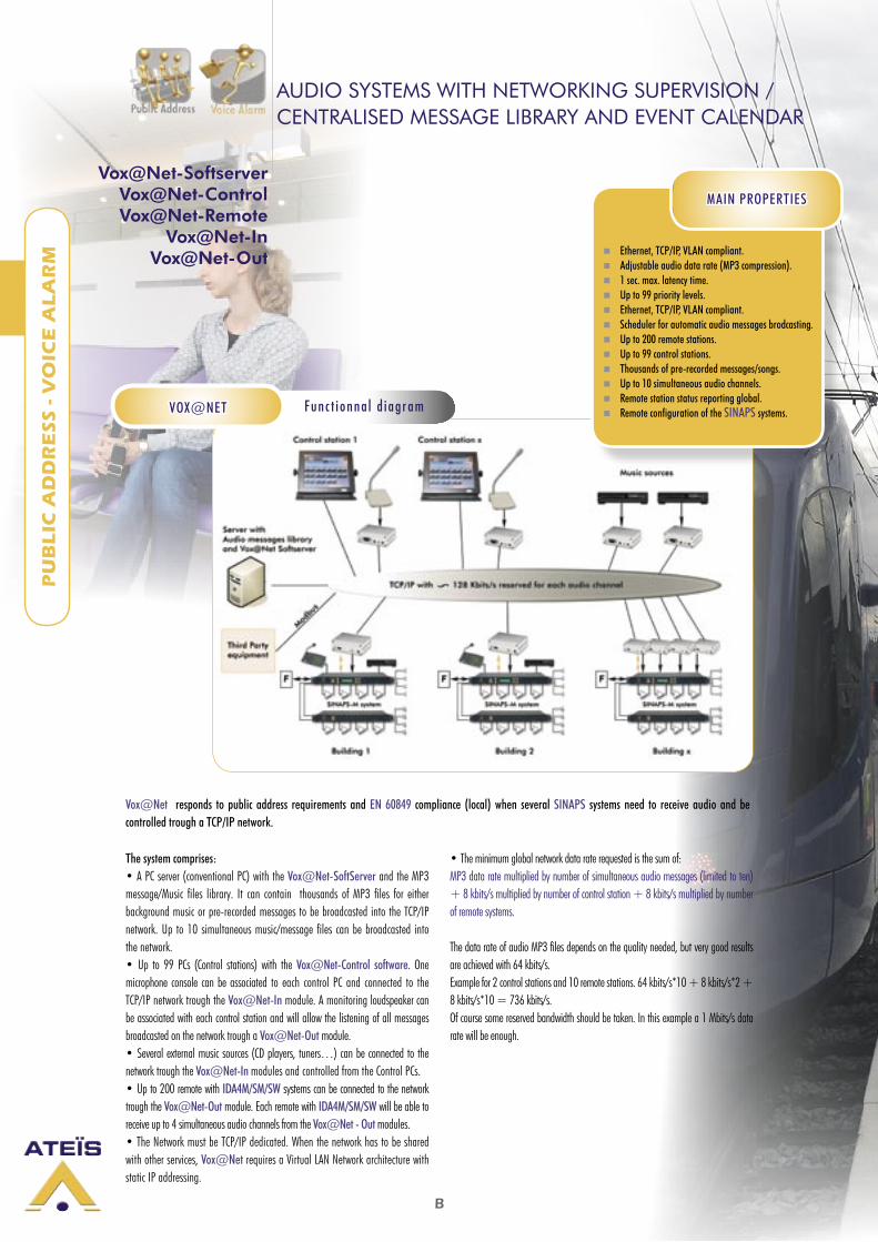
The system comprises:• A PC server (conventional PC) with the Vox@Net-SoftServer and the MP3 message/Music files library. It can contain thousands of MP3 files for either background music or pre-recorded messages to be broadcasted into the TCP/IP network. Up to 10 simultaneous music/message files can be broadcasted into the network.• Up to 99 PCs (Control stations) with the Vox@Net-Control software. One microphone console can be associated to each control PC and connected to the TCP/IP network trough the Vox@Net-In module. A monitoring loudspeaker can be associated with each control station and will allow the listening of all messages broadcasted on the network trough a Vox@Net-Out module.• Several external music sources (CD players, tuners…) can be connected to the network trough the Vox@Net-In modules and controlled from the Control PCs.• Up to 200 remote with IDA4M/SM/SW systems can be connected to the network trough the Vox@Net-Out module. Each remote with IDA4M/SM/SW will be able to receive up to 4 simultaneous audio channels from the Vox@Net - Out modules. • The Network must be TCP/IP dedicated. When the network has to be shared with other services, Vox@Net requires a Virtual LAN Network architecture with static IP addressing.
• The minimum global network data rate requested is the sum of:MP3 data rate multiplied by number of simultaneous audio messages (limited to ten) + 8 kbits/s multiplied by number of control station + 8 kbits/s multiplied by number of remote systems.
The data rate of audio MP3 files depends on the quality needed, but very good results are achieved with 64 kbits/s.Example for 2 control stations and 10 remote stations. 64 kbits/s*10 + 8 kbits/s*2 + 8 kbits/s*10 = 736 kbits/s. Of course some reserved bandwidth should be taken. In this example a 1 Mbits/s data rate will be enough.
Vox@Net responds to public address requirements and EN 60849 compliance (local) when several SINAPS systems need to receive audio and be controlled trough a TCP/IP network.
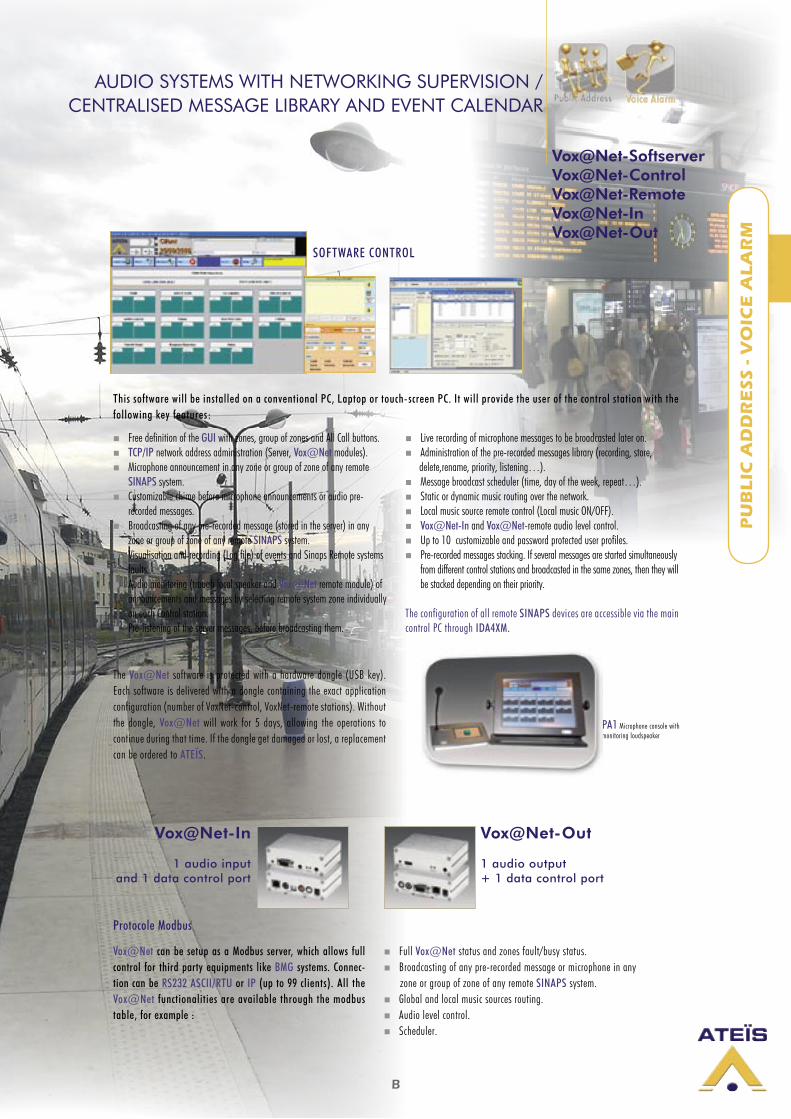
AUDIO SYSTEMS WITH NETWORKING SUPERVISION / CENTRALISED MESSAGE LIBRARY AND EVENT CALENDAR
Fun c t i onna l d i ag ramVOX@NET
Ethernet, TCP/IP, VLAN compliant. Adjustable audio data rate (MP3 compression). 1 sec. max. latency time. Up to 99 priority levels. Ethernet, TCP/IP, VLAN compliant. Scheduler for automatic audio messages brodcasting. Up to 200 remote stations. Up to 99 control stations. Thousands of pre-recorded messages/songs. Up to 10 simultaneous audio channels. Remote station status reporting global. Remote configuration of the SINAPS systems.
MAIN PROPERTIES
B
PU
BL
IC A
DD
RE
SS
- V
OIC
E A
LA
RM
Vox@Net-In
1 audio input and 1 data control port
Vox@Net-Out
1 audio output + 1 data control port
The Vox@Net software is protected with a hardware dongle (USB key). Each software is delivered with a dongle containing the exact application configuration (number of VoxNet-control, VoxNet-remote stations). Without the dongle, Vox@Net will work for 5 days, allowing the operations to continue during that time. If the dongle get damaged or lost, a replacement can be ordered to ATEÏS.
PA1 Microphone console withmonitoring loudspeaker
Protocole Modbus
Vox@Net can be setup as a Modbus server, which allows full control for third party equipments like BMG systems. Connec-tion can be RS232 ASCII/RTU or IP (up to 99 clients). All the Vox@Net functionalities are available through the modbus table, for example :
Full Vox@Net status and zones fault/busy status. Broadcasting of any pre-recorded message or microphone in any zone or group of zone of any remote SINAPS system. Global and local music sources routing. Audio level control. Scheduler.
Free definition of the GUI with zones, group of zones and All Call buttons. TCP/IP network address administration (Server, Vox@Net modules). Microphone announcement in any zone or group of zone of any remote
SINAPS system. Customizable chime before microphone announcements or audio pre-
recorded messages. Broadcasting of any pre-recorded message (stored in the server) in any
zone or group of zone of any remote SINAPS system. Visualisation and recording (Log file) of events and Sinaps Remote systems
faults. Audio monitoring (trough local speaker and Vox@Net remote module) of
announcements and messages by selecting remote system zone individually on each Control station.
Pre-listening of the server messages, before broadcasting them.
Live recording of microphone messages to be broadcasted later on. Administration of the pre-recorded messages library (recording, store, delete,rename, priority, listening…). Message broadcast scheduler (time, day of the week, repeat…). Static or dynamic music routing over the network. Local music source remote control (Local music ON/OFF). Vox@Net-In and Vox@Net-remote audio level control. Up to 10 customizable and password protected user profiles. Pre-recorded messages stacking. If several messages are started simultaneously
from different control stations and broadcasted in the same zones, then they will be stacked depending on their priority.
The configuration of all remote SINAPS devices are accessible via the main control PC through IDA4XM.
SOFTWARE CONTROL
AUDIO SYSTEMS WITH NETWORKING SUPERVISION / CENTRALISED MESSAGE LIBRARY AND EVENT CALENDAR
Vox@Net-SoftserverVox@Net-ControlVox@Net-RemoteVox@Net-InVox@Net-Out
This software will be installed on a conventional PC, Laptop or touch-screen PC. It will provide the user of the control station with the following key features:
B
PU
BL
IC A
DD
RE
SS
- V
OIC
E A
LA
RM
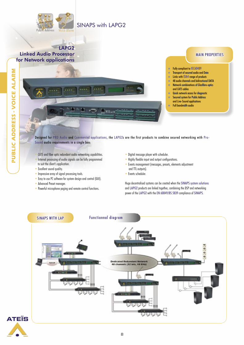
SINAPS with LAPG2
LAPG2Linked Audio Processor
for Network applications
Fully compliant to IEC60489 Transport of secured audio and Data Links with IDA4 range of products 48 audio channels and bidirectional DATA Network combinations of Glasfibre-optics
and CAT5 cables Quick network access for diagnostic Secured system for Public Address
and Live-Sound applications Full bandwidth audio
MAIN PROPERTIES
• CAT5 and fiber optic redundant audio networking capabilities.• Internal processing of audio signals can be fully programmed to suit the client’s application.• Excellent sound quality.• Impressive array of signal processing tools.• Easy to use PC software for system design and control (GUI).• Advanced Preset manager.• Powerful microphone paging and remote control functions.
• Digital message player with scheduler.• Highly flexible input and output configurations.• Events management (messages, presets, elements adjustment and TTL outputs).• Events scheduler.
Huge decentralised systems can be created when the SINAPS system solutions and LAPG2 products are linked together, combining the DSP and networking power of the LAPG2 with the EN 60849/BS 5839 compliance of SINAPS.
Fun c t i onna l d i ag ramSINAPS WITH LAP
Designed for PRO Audio and Commercial applications, the LAPG2s are the first products to combine secured networking with Pro-Sound audio requirements in a single box:
B
PU
BL
IC A
DD
RE
SS
- V
OIC
E A
LA
RM
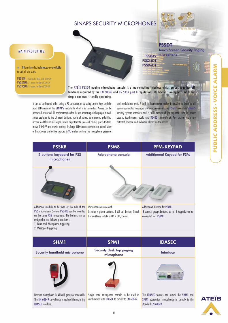
SHM1 SPM1 IDASEC
Security handheld microphoneSecurity desk top paging
microphoneInterface
Firemen microphone for All call, group or zone calls. The EN 60849 surveillance is realised thanks to the IDASEC interface.
Single zone microphone console to be used in combination with IDASEC to comply to EN 60849.
The IDASEC secures and surveil the SHM1 and SPM1 evacuation microphones to comply to the standard EN 60849.
PSSKB PSM8 PPM-KEYPAD
2 buttons keyboard for PSS microphones
Microphone console Additionnal Keypad for PSM
Additional module to be fixed at the side of the PSS microphone. Several PSS-KB can be mounted on the same PSS microphone. The buttons can be assigned to the following functions :1) Fault back Microphone triggering2) Messages triggering
Microphone console with: 8 zones / group buttons, 1 All call button, Speak button (Press to talk or ON / OFF, chime)
Additionnal Keypad for PSM8: 8 zones / groups buttons, up to 11 keypads can be connected to 1 PSM8.
Different product references are available to suit all site sizes:
PSS849: 12 zones for IDA4 and 4XM/SWPSS24DT: 24 zones for IDA4M/XM/SWPSS96DT: 96 zones for IDA4M/XM/SW
It can be configured either using a PC computer, or by using control keys and the front LCD screen of the SINAPS module to which it is connected. Access can be password-protected. All parameters needed for site operating can be programmed: zones assigned to the different buttons, name of zones, zone groups, priorities, access to different messages, levels adjustments, pre-call chime, press-to-talk, music ON/OFF and music routing. Its large LCD screen provides an overall view of busy zones and active sources. A VU meter controls the microphone presence
and modulation level. A built-in loudspeaker makes it possible to listen to all system-generated messages and announcements. The PSSDT console is SINAPS security system interface and is fully monitored (microphone capsule, power supply, touchscreen, audio and RS485 connections). Any system faults are detected, located and indicated clearly on the screen.
SINAPS SECURITY MICROPHONES
MAIN PROPERTIESPSS849
PSS24DTPSS96DT
PSSDTTouch Screen Security Paging microphone
The ATEÏS PSSDT paging microphone console is a man-machine interface which groups together all functions required by the EN 60849 and BS 5839 part 8 regulations. Its back-lit touchpad is made for simple and user-friendly operating.
B
PU
BL
IC A
DD
RE
SS
- V
OIC
E A
LA
RM
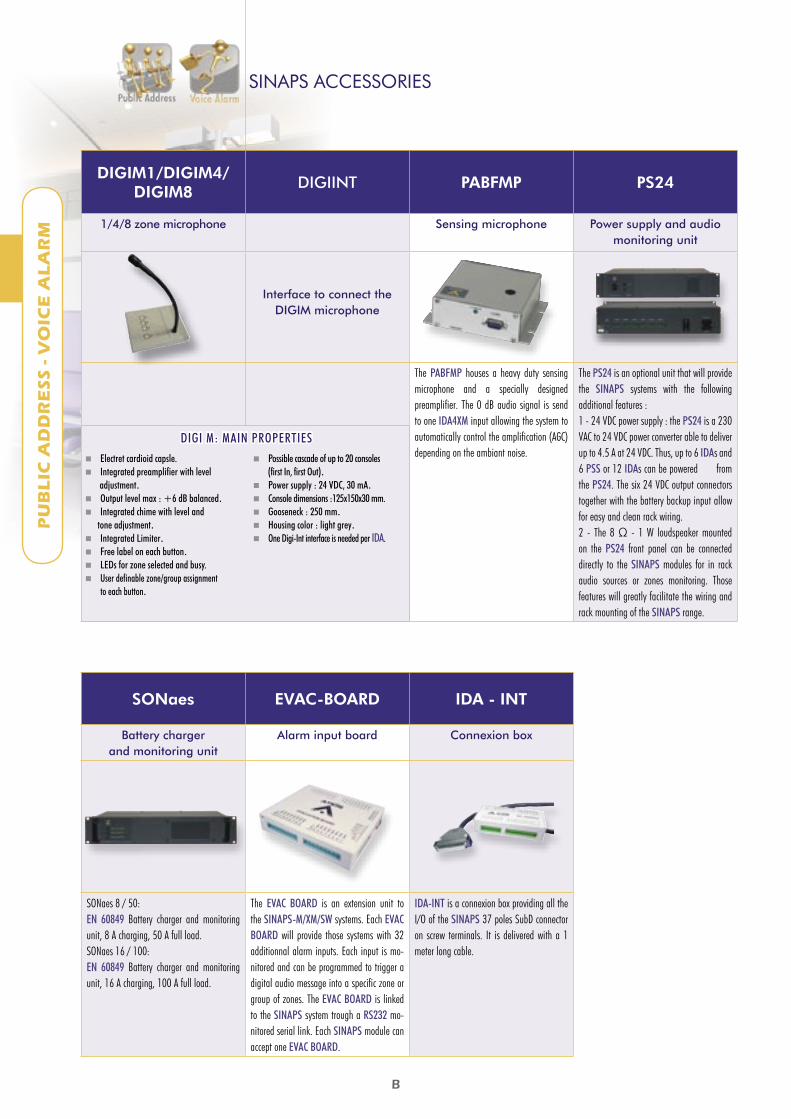
DIGIM1/DIGIM4/DIGIM8
DIGIINT PABFMP PS24
1/4/8 zone microphone Sensing microphone Power supply and audio monitoring unit
Interface to connect the DIGIM microphone
The PABFMP houses a heavy duty sensing microphone and a specially designed preamplifier. The 0 dB audio signal is send to one IDA4XM input allowing the system to automatically control the amplification (AGC) depending on the ambiant noise.
The PS24 is an optional unit that will provide the SINAPS systems with the following additional features :1 - 24 VDC power supply : the PS24 is a 230 VAC to 24 VDC power converter able to deliver up to 4.5 A at 24 VDC. Thus, up to 6 IDAs and 6 PSS or 12 IDAs can be powered from the PS24. The six 24 VDC output connectors together with the battery backup input allow for easy and clean rack wiring.2 - The 8 Ω - 1 W loudspeaker mounted on the PS24 front panel can be connected directly to the SINAPS modules for in rack audio sources or zones monitoring. Those features will greatly facilitate the wiring and rack mounting of the SINAPS range.
SONaes EVAC-BOARD IDA - INT
Battery charger and monitoring unit
Alarm input board Connexion box
SONaes 8 / 50:EN 60849 Battery charger and monitoring unit, 8 A charging, 50 A full load.SONaes 16 / 100:EN 60849 Battery charger and monitoring unit, 16 A charging, 100 A full load.
The EVAC BOARD is an extension unit to the SINAPS-M/XM/SW systems. Each EVAC BOARD will provide those systems with 32 additionnal alarm inputs. Each input is mo-nitored and can be programmed to trigger a digital audio message into a specific zone or group of zones. The EVAC BOARD is linked to the SINAPS system trough a RS232 mo-nitored serial link. Each SINAPS module can accept one EVAC BOARD.
IDA-INT is a connexion box providing all the I/O of the SINAPS 37 poles SubD connector on screw terminals. It is delivered with a 1 meter long cable.
SINAPS ACCESSORIES
Electret cardioid capsle. Integrated preamplifier with level adjustment. Output level max : +6 dB balanced. Integrated chime with level and tone adjustment. Integrated Limiter. Free label on each button. LEDs for zone selected and busy. User definable zone/group assignment to each button.
Possible cascade of up to 20 consoles (first In, first Out). Power supply : 24 VDC, 30 mA. Console dimensions :125x150x30 mm. Gooseneck : 250 mm. Housing color : light grey. One Digi-Int interface is needed per IDA.
DIGI M: MAIN PROPERTIES
B
PU
BL
IC A
DD
RE
SS
- V
OIC
E A
LA
RM
SPA21202 x 120 W100 V
SPA22402 x 240 W100 V
SPA20602 x 60 W100 V
SECURITY AMPLIFIERS
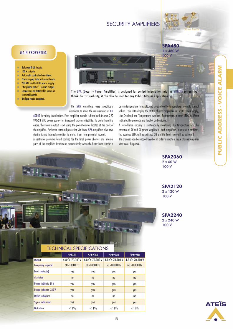
Balanced 0 db inputs. 100 V outputs. Automatic controlled ventilator. Power supply internal surveillance. 230 VAC and 24 VDC power supply. ‘’Amplifier status’’ contact output. Connexions on detachable screw-on terminal boards. Bridged mode accepted.
MAIN PROPERTIES
SPA4801 x 480 W 100 V
SPA480 SPA2060 SPA2120 SPA2240Output 4-8 Ω 70-100 V 4-8 Ω 70-100 V 4-8 Ω 70-100 V 4-8 Ω 70-100 VFrequency respond 60 -18000 Hz 60 -18000 Hz 60 -18000 Hz 60 -18000 Hz
Fault contact(s) yes yes yes yes
ok-status no no no no
Power Indicatie 24 V yes yes yes yes
Power Indicatie 230 V yes yes yes yes
Defect indication no no no no
Signal indication yes yes yes yes
Distortion < 1% < 1% < 1% < 1%
TECHNICAL SPECIFICATIONS
The SPA amplifiers were specifically developed to meet the requirements of EN
60849 for safety installations. Each amplifier module is fitted with its own 220 VAC/24 VDC power supply for increased system reliability. To avoid handling errors, the volume output is set using the potentiometer located at the back of the amplifier. Further to standard protection via fuses, SPA amplifiers also have electronic and thermal protection to protect them from potential hazards.A ventilator provides forced cooling for the final power shelves and internal parts of the amplifier. It starts up automatically when the heat shunt reaches a
certain temperature threshold, and stops when the temperature returns to normal values. Four LEDs display the status of each amplifiers: AC or DC power supply, Line Overload and Temperature overload. Furthermore, a three LEDs Vu-Meter indicates the presence and level of audio signal.A surveillance circuitry is continuously monitoring the temperature and the presence of AC and DC power supplies for both amplifiers. In case of a problem, the overload LEDs will be switched ON and the Fault relay will be activated. The channels can be bridged together in order to create a single channel amplifier with twice the power.
The SPA (Security Power Amplifier) is designed for perfect integration into the SINAPS system, but thanks to its flexibility, it can also be used for any Public Address application.
B
PU
BL
IC A
DD
RE
SS
- V
OIC
E A
LA
RM
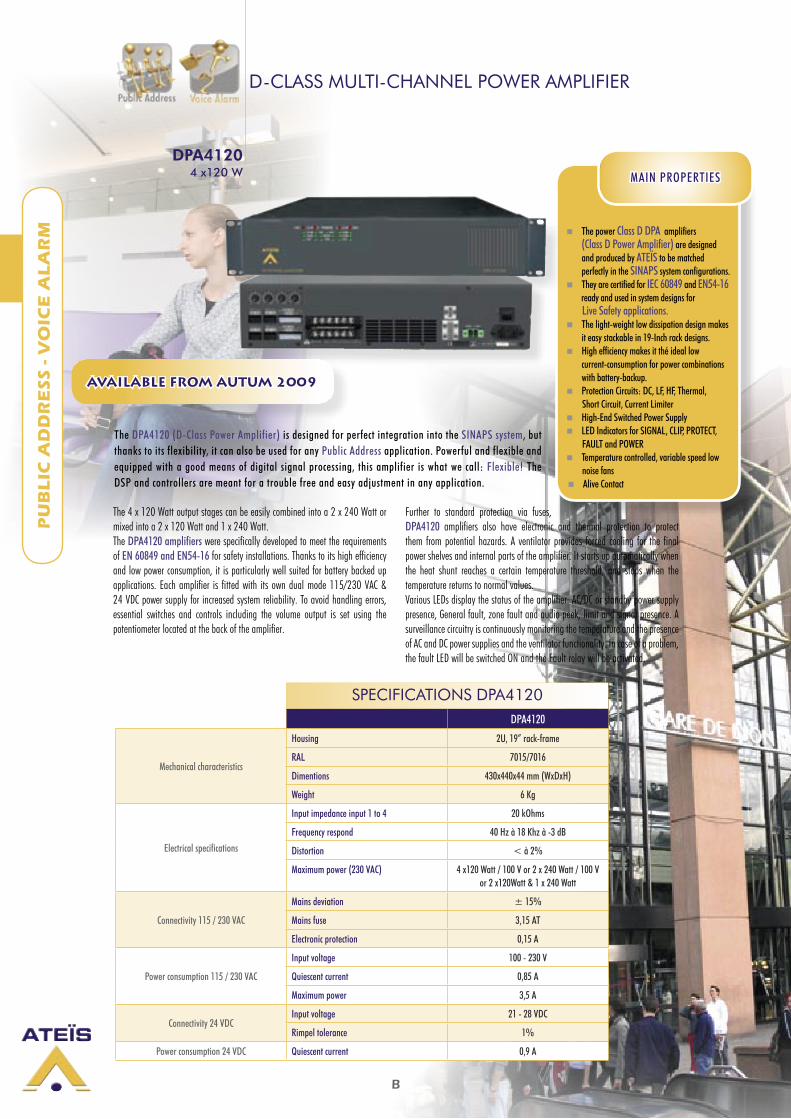
D-CLASS MULTI-CHANNEL POWER AMPLIFIER
The power Class D DPA amplifiers (Class D Power Amplifier) are designed and produced by ATEÏS to be matched perfectly in the SINAPS system configurations.
They are certified for IEC 60849 and EN54-16 ready and used in system designs for Live Safety applications. The light-weight low dissipation design makes
it easy stackable in 19-Inch rack designs. High efficiency makes it thé ideal low
current-consumption for power combinations with battery-backup.
Protection Circuits: DC, LF, HF, Thermal, Short Circuit, Current Limiter High-End Switched Power Supply LED Indicators for SIGNAL, CLIP, PROTECT, FAULT and POWER Temperature controlled, variable speed low noise fans Alive Contact
MAIN PROPERTIES
The 4 x 120 Watt output stages can be easily combined into a 2 x 240 Watt or mixed into a 2 x 120 Watt and 1 x 240 Watt. The DPA4120 amplifiers were specifically developed to meet the requirements of EN 60849 and EN54-16 for safety installations. Thanks to its high efficiency and low power consumption, it is particularly well suited for battery backed up applications. Each amplifier is fitted with its own dual mode 115/230 VAC & 24 VDC power supply for increased system reliability. To avoid handling errors, essential switches and controls including the volume output is set using the potentiometer located at the back of the amplifier.
Further to standard protection via fuses, DPA4120 amplifiers also have electronic and thermal protection to protect them from potential hazards. A ventilator provides forced cooling for the final power shelves and internal parts of the amplifier. It starts up automatically when the heat shunt reaches a certain temperature threshold, and stops when the temperature returns to normal values.Various LEDs display the status of the amplifier: AC/DC or standby power supply presence, General fault, zone fault and audio peek, limit and signal presence. A surveillance circuitry is continuously monitoring the temperature and the presence of AC and DC power supplies and the ventilator functionality. In case of a problem, the fault LED will be switched ON and the Fault relay will be activated.
DPA41204 x120 W
SPECIFICATIONS DPA4120DPA4120
Mechanical characteristics
Housing 2U, 19” rack-frame
RAL 7015/7016
Dimentions 430x440x44 mm (WxDxH)
Weight 6 Kg
Electrical specifications
Input impedance input 1 to 4 20 kOhms
Frequency respond 40 Hz à 18 Khz à -3 dB
Distortion < à 2%
Maximum power (230 VAC) 4 x120 Watt / 100 V or 2 x 240 Watt / 100 V or 2 x120Watt & 1 x 240 Watt
Connectivity 115 / 230 VAC
Mains deviation ± 15%
Mains fuse 3,15 AT
Electronic protection 0,15 A
Power consumption 115 / 230 VAC
Input voltage 100 - 230 V
Quiescent current 0,85 A
Maximum power 3,5 A
Connectivity 24 VDCInput voltage 21 - 28 VDC
Rimpel tolerance 1%
Power consumption 24 VDC Quiescent current 0,9 A
AVAILABLE FROM AUTUM 2009
The DPA4120 (D-Class Power Amplifier) is designed for perfect integration into the SINAPS system, but thanks to its flexibility, it can also be used for any Public Address application. Powerful and flexible and equipped with a good means of digital signal processing, this amplifier is what we call: Flexible! The DSP and controllers are meant for a trouble free and easy adjustment in any application.
C
CO
MM
ER
CIA
L A
UD
IO
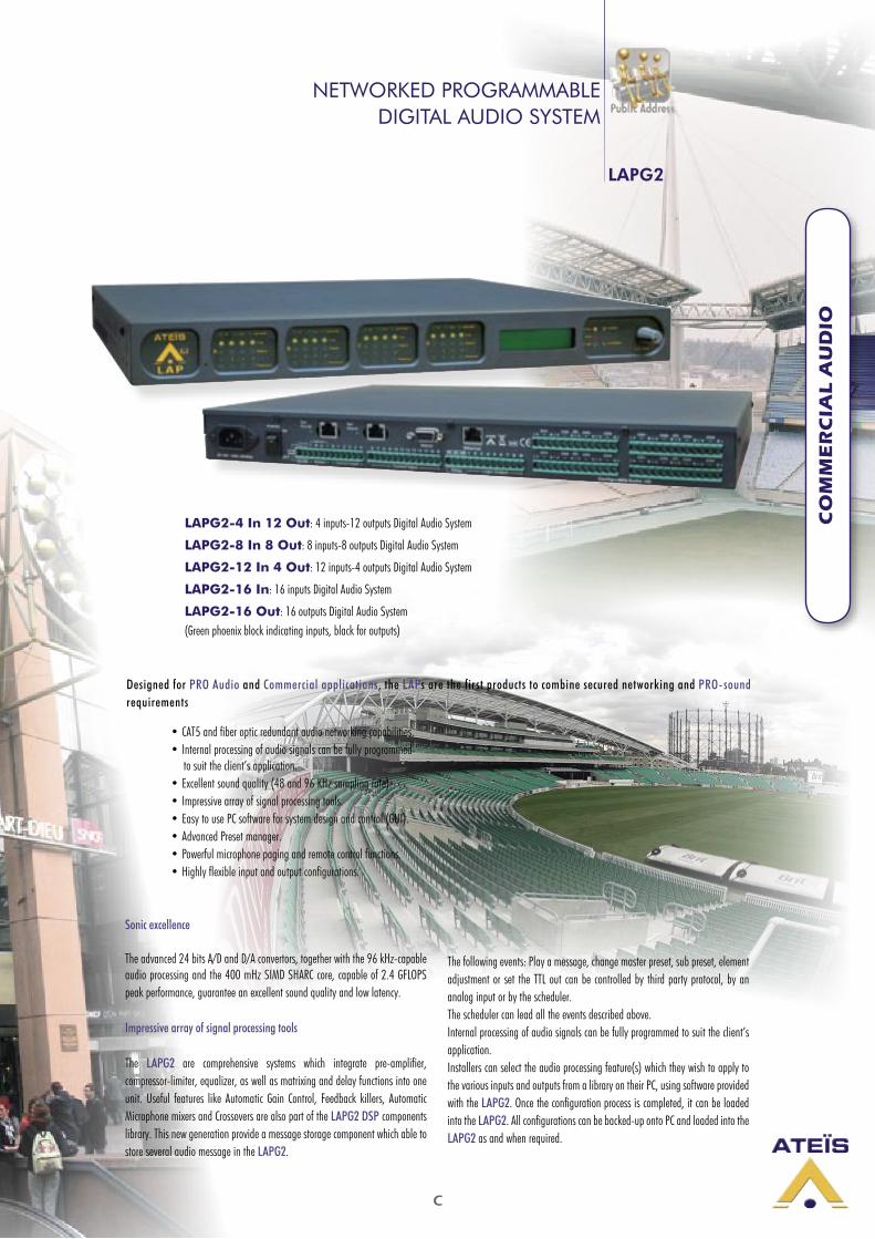
NETWORKED PROGRAMMABLEDIGITAL AUDIO SYSTEM
LAPG2
LAPG2-4 In 12 Out: 4 inputs-12 outputs Digital Audio System
LAPG2-8 In 8 Out: 8 inputs-8 outputs Digital Audio System
LAPG2-12 In 4 Out: 12 inputs-4 outputs Digital Audio System
LAPG2-16 In: 16 inputs Digital Audio System
LAPG2-16 Out: 16 outputs Digital Audio System(Green phoenix block indicating inputs, black for outputs)
• CAT5 and fiber optic redundant audio networking capabilities.• Internal processing of audio signals can be fully programmed
to suit the client’s application.• Excellent sound quality (48 and 96 KHz sampling rate).• Impressive array of signal processing tools.• Easy to use PC software for system design and control (GUI).• Advanced Preset manager.• Powerful microphone paging and remote control functions.• Highly flexible input and output configurations.
Sonic excellence
The advanced 24 bits A/D and D/A convertors, together with the 96 kHz-capable audio processing and the 400 mHz SIMD SHARC core, capable of 2.4 GFLOPS peak performance, guarantee an excellent sound quality and low latency.
Impressive array of signal processing tools
The LAPG2 are comprehensive systems which integrate pre-amplifier, compressor-limiter, equalizer, as well as matrixing and delay functions into one unit. Useful features like Automatic Gain Control, Feedback killers, Automatic Microphone mixers and Crossovers are also part of the LAPG2 DSP components library. This new generation provide a message storage component which able to store several audio message in the LAPG2.
The following events: Play a message, change master preset, sub preset, element adjustment or set the TTL out can be controlled by third party protocol, by an analog input or by the scheduler.The scheduler can lead all the events described above.Internal processing of audio signals can be fully programmed to suit the client’s application.Installers can select the audio processing feature(s) which they wish to apply to the various inputs and outputs from a library on their PC, using software provided with the LAPG2. Once the configuration process is completed, it can be loaded into the LAPG2. All configurations can be backed-up onto PC and loaded into the LAPG2 as and when required.
Designed for PRO Audio and Commercial applications, the LAPs are the first products to combine secured networking and PRO-sound requirements

C
CO
MM
ER
CIA
L A
UD
IO
Easy to use PC software for system design and control (GUI)
Advanced Preset managerThe LAP includes two types of presets :
More than 20 Parameter presets : they enable values of multiple parameters of the same design, such as levels, gains, EQ, etc. to be restored either from the PC software, the remote controllers or the control inputs.
More than 10 Design presets : they enable completely different designs to be restored. An application example for this feature are hotel meeting rooms with removable walls.
Remote control functions
To maintain simple, secure and intuitive interfaces for operators, the LAP offers different types of remote controllers:
Furthermore, LAPG2 now provides a TCP/IP port with RJ45 connector. PC-based custom control panels can now operate the LAPG2 from remote locations through a TCP/IP network.
RAC5 - RAC8Wall-mounted level and 5 or 8 sources selectors
URCProgrammable
Remote controller with display
NETWORKED PROGRAMMABLEDIGITAL AUDIO SYSTEM
LAPG2
The LAP-DESIGNER PC software provides all the necessary tools to setup and control the hardware and software elements of the LAP.

C
CO
MM
ER
CIA
L A
UD
IO
NETWORKED PROGRAMMABLEDIGITAL AUDIO SYSTEM
16 Analogue control inputs
The LAPG2 has 16 control inputs which can be configured as analog control input (0 to 5 VDC_ or as logic input (TTL) Each control can be associated to any of the variable audio processing functions of the LAPG2 (input level, output level, equalization, routing). Several parameters (Min + Max values, positive or negative variation, linear, log, anti-log) can be programmed for each of those controls.
16 Logic inputs, 8 Logic outputs (GPIOs)
In addition of the logic inputs, each LAPG2 is also equipped with 8 logic outputs (TTL). Each of those hardware input/output’s can be associated to virtually any software button the system designer requires to.The logic inputs could be use to mute or activate an audio signal while the logic outputs enable the LAPG2 to control external equipment. The logic inputs can be used in normal or binary mode.
RS-232 serial interfacing for third party control
The LAPG2 can be controlled from third party equipment like Vity, AMX or Crestron via its RS232 serial port. The RS232 link will also be used to control the SINAPS voice alarm equipment from the LAPG2.
Microphone paging
The LAPG2 can support the following paging microphones:
PPM-8: microphone console with - 8 zones/groups buttons - 1 All call button - Speak button (Press to talk or ON / OFF, pre and post chime). - Internal speakers
PPM Keypad: additionnal Keypad for PPM8 - 8 zones/groups buttons - Up to 11 Keypads can be connected to 1 PPM8.
Junction Box Easy chain-connection of LAPG2 peripherals (URC and PPM), using standard CAT5 cables.
LAPG2
PPM-8 PPM Keypad
C
CO
MM
ER
CIA
L A
UD
IO
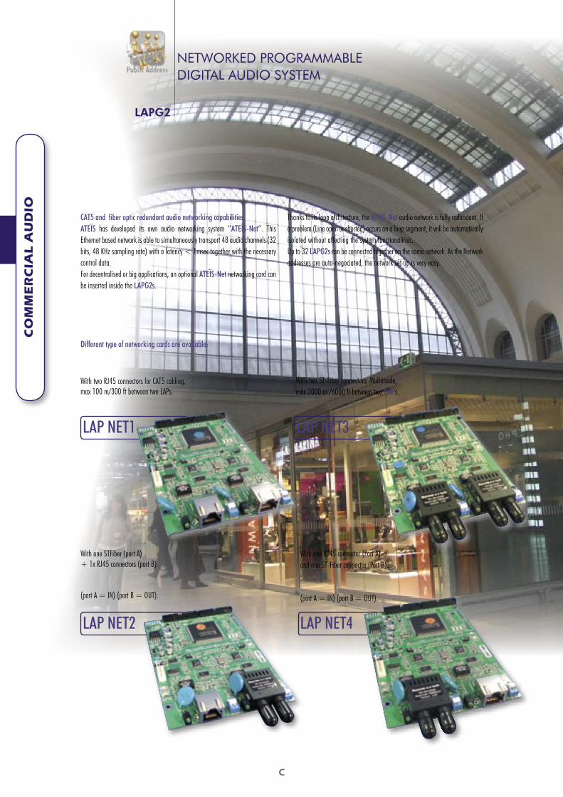
CAT5 and fiber optic redundant audio networking capabilitiesATEÏS has developed its own audio networking system ‘’ATEÏS-Net’’. This Ethernet based network is able to simultaneously transport 48 audio channels (32 bits, 48 KHz sampling rate) with a latency < 1msec together with the necessary control data. For decentralised or big applications, an optional ATEÏS-Net networking card can be inserted inside the LAPG2s.
Thanks to its loop architecture, the ATEÏS-Net audio network is fully redundant. If a problem (Line open or shorted) occurs on a loop segment, it will be automatically isolated without affecting the system functionalities.Up to 32 LAPG2s can be connected together on the same network. As the Network addresses are auto-negociated, the network set up is very easy.
LAP NET4
With one RJ45 connector (Port A) and one ST-Fiber connector (Port B).
(port A = IN) (port B = OUT).
With two ST-Fiber connectors, Multimode, max 2000 m /6000 ft between two LAPs.
LAP NET3
With one STFiber (port A) + 1x RJ45 connectors (port B).
(port A = IN) (port B = OUT).
LAP NET2
With two RJ45 connectors for CAT5 cabling, max 100 m/300 ft between two LAPs.
LAP NET1
Different type of networking cards are available:
NETWORKED PROGRAMMABLEDIGITAL AUDIO SYSTEM
LAPG2
C
CO
MM
ER
CIA
L A
UD
IO
LAP
NETWORKED PROGRAMMABLEDIGITAL AUDIO SYSTEM
LAPG2
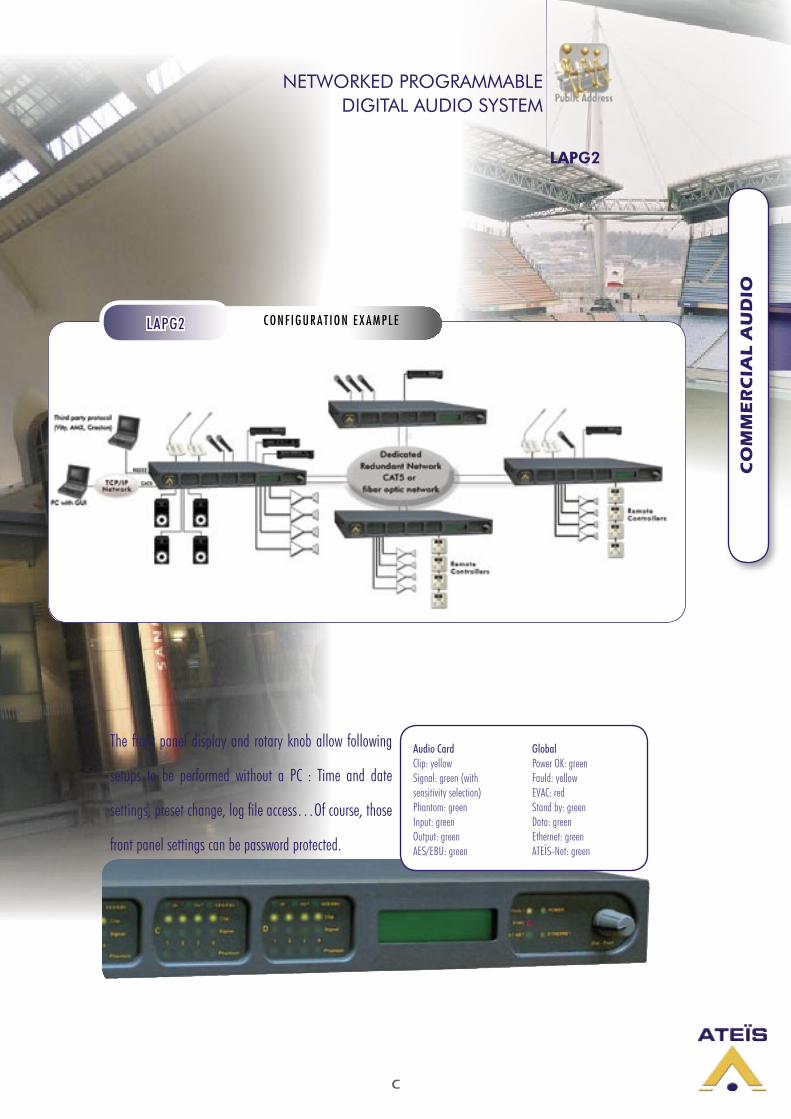
CONF IGURAT ION EXAMPLELAPG2
The front panel display and rotary knob allow following
setups to be performed without a PC : Time and date
settings, preset change, log file access…Of course, those
front panel settings can be password protected.
Audio CardClip: yellowSignal: green (with sensitivity selection)Phantom: greenInput: greenOutput: greenAES/EBU: green
GlobalPower OK: greenFauld: yellowEVAC: redStand by: greenData: greenEthernet: greenATEÏS-Net: green

C
CO
MM
ER
CIA
L A
UD
IO
FULLY PROGRAMMABLE AUDIO MATRIX,8 INPUTS - 8 OUTPUTS
UAP88
Internal processing of audio signals can be fully programmed to suit the client’s application.Installers can select the audio processing feature(s) which they wish to apply to the various inputs and outputs from a library on their PC, using software provided with the UAP. Once the configuration process is complete, it can be loaded into the UAP. All configurations can be backed-up onto PC and loaded into the UAP as and when required.The user interface comprises 8 rotary knobs on the front and 6 (0 to 5 VDC) analogue control inputs at the back. Each control can be associated to any of the variable audio processing functions of the UAP (input level, output level, source selection, routing, perset change...). The RAC5 and RAC8 ATEÏS DC remote controllers are ideally suited to be connected to the analogue control inputs for Level and Source Selection.The UAP can also be controlled via an external system such as Vity, Crestron, AMX, or via a PC using an operating program provided with the UAP. This program makes it possible, for example, to load a map or picture of the site and to only integrate the settings which we wish to make available to the final user.The UAP processor has 8 universal balanced audio inputs and 8 balanced audio outputs. It is also fitted with 8 inputs (TTL) and 8 logic outputs (TTL). Each of those hardware input/output can be associated to virtually any software button the system designer requires. The logic inputs can be use to load a preset, mute or
activate an audio signal, while the logic outputs enable the UAP to control external equipment. The UAP processor presents the end user with state-of-the-art technology, while remaining extremely user-friendly thanks to its user interface.
All of these functions make UAP the all-round product for audio applications requiring signal processing, such as churches, auditoriums, congress centres, night clubs, pubs and many other public places.
8 balanced audio inputs (-55 dB to 0 dB switchable). Balanced audio outputs (0 dB). Switchable Phantom Power supply. 8 logic inputs and 8 logic output (TTL). 6 analogue control inputs (0 to 5 VDC). 1 RS232 connection for configuration and
remote control.
MAIN FEATURES
RAC5 RAC8
Wall-mounted. Level control and 5 sources selectors
Wall-mounted. Level controland 8 sources selectors
A U D I O P R O C E S S I N G E X A M P L E
A C C E S S O R I E S
The UAP digital-audio processor is a comprehensive system which integrates pre-amplifier, compressor-limiter, equalizer, as well as matrixing and delay functions into one unit. Usefull features like Automatic Gain Control, Feedback killers, Automatic Microphone mixes and Crossovers are also part of the UAP impressive DSP components library. Thanks to its Page Control DSP component, the UAP is able to manage up to 8 microphones (VOX or contact activation) with different priority levels.

C
CO
MM
ER
CIA
L A
UD
IO
FULLY PROGRAMMABLE AUDIO MATRIX,8 INPUTS - 8 OUTPUTS
UAP88
CONF IGURAT ION EXAMPLEUAP88
Input ControlEach input can be disabled (Mute) or programmed for contact activation (C1 to C8). The input level can be adjusted and the Phantom power supply can be selected. VU meter display the different signal levels.
Gate Control Each input can be activated by signal detection (Attack time, Release time and Level settings).
Crossovers 2 ways, 3 ways, 4 ways with Butterworth, Linkwitz and Bessel curves slope selectable.
P.E.Q 2 to 16-band Parametric filters.
Filters High-Low Pass, Band Pass, Notch filters (Butterworth, Linkwitz-Riley, Bessel curves)
Matrix Mixer Matrixes 4 x 4 stereo and 8 x 8 mono with independent level settings for each input and output.
Delay Delay from 1 to 500 msecs. on output 1 to 8.
Compressor/Limiter Compressor/Limiter (Attack time, Release time, Threshold and Ratio settings).
Output Control Each output level can be adjusted. VU meters display the different signal levels.
AutomaticMicrophone Mixer 4, 8 or 16 inputs to 1 output. Manual or automatic priority, AGC, all levels adjustable.
Feedback killer Automatic feedback frequency search and filtering. Several filter types, sensivity and levels can be adjusted.
Page Control Routing matrix with contact or VOX input activation, 8 priority levels.
Source Selection Source selection module associated to one of the Analogue control inputs.
D S P C O M P O N E N T S
C
CO
MM
ER
CIA
L A
UD
IO
STACKABLE AND FULLY PROGRAMMABLE AUDIO PROCESSOR WITH ENHANCED DSP - POWER
UAPG2
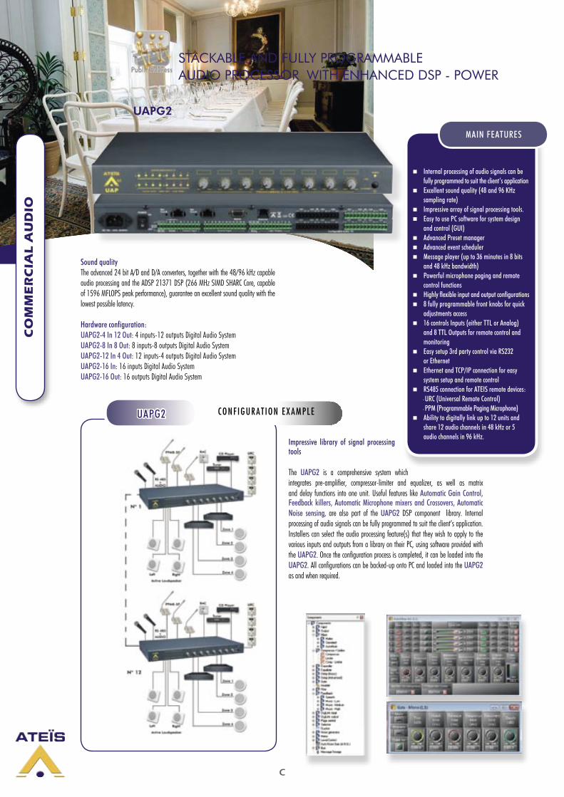
Sound qualityThe advanced 24 bit A/D and D/A converters, together with the 48/96 kHz capable audio processing and the ADSP 21371 DSP (266 MHz SIMD SHARC Core, capable of 1596 MFLOPS peak performance), guarantee an excellent sound quality with the lowest possible latency.
Hardware configuration:UAPG2-4 In 12 Out: 4 inputs-12 outputs Digital Audio SystemUAPG2-8 In 8 Out: 8 inputs-8 outputs Digital Audio SystemUAPG2-12 In 4 Out: 12 inputs-4 outputs Digital Audio SystemUAPG2-16 In: 16 inputs Digital Audio SystemUAPG2-16 Out: 16 outputs Digital Audio System
Impressive library of signal processing tools
The UAPG2 is a comprehensive system which integrates pre-amplifier, compressor-limiter and equalizer, as well as matrix and delay functions into one unit. Useful features like Automatic Gain Control, Feedback killers, Automatic Microphone mixers and Crossovers, Automatic Noise sensing, are also part of the UAPG2 DSP component library. Internal processing of audio signals can be fully programmed to suit the client’s application. Installers can select the audio processing feature(s) that they wish to apply to the various inputs and outputs from a library on their PC, using software provided with the UAPG2. Once the configuration process is completed, it can be loaded into the UAPG2. All configurations can be backed-up onto PC and loaded into the UAPG2 as and when required.
Internal processing of audio signals can befully programmed to suit the client’s application
Excellent sound quality (48 and 96 KHzsampling rate)
Impressive array of signal processing tools. Easy to use PC software for system design
and control (GUI) Advanced Preset manager Advanced event scheduler Message player (up to 36 minutes in 8 bits
and 48 kHz bandwidth) Powerful microphone paging and remote
control functions Highly flexible input and output configurations 8 fully programmable front knobs for quick
adjustments access 16 controls Inputs (either TTL or Analog)
and 8 TTL Outputs for remote control and monitoring
Easy setup 3rd party control via RS232or Ethernet
Ethernet and TCP/IP connection for easysystem setup and remote control
RS485 connection for ATEIS remote devices: - URC (Universal Remote Control) - PPM (Programmable Paging Microphone) Ability to digitally link up to 12 units and
share 12 audio channels in 48 kHz or 5 audio channels in 96 kHz.
MAIN FEATURES
CONF IGURAT ION EXAMPLEUAPG2
C
CO
MM
ER
CIA
L A
UD
IO
Easy to use PC software for system design and control (GUI)
The UAPG2-DESIGNER PC software provides all the necessary tools to set up and control the hardware and software elements of the UAPG2.
Advanced Preset managerThe UAPG2 includes two types of presets:More than 20 Parameter presets: They enable values of multiple parameters of the same design, such as levels, gains, EQ, etc. to be restored either from the PC software, the remote controllers or the control inputs.
More than 10 Design presets: they enable completely different designs to be restored. Application examples for this feature are hotel meeting rooms with removable walls.
Message player The Message player incorporated into the UAPG2 allows you to play any kind of message to be played. Only one message per UAPG2 can be run at a time. With the 100 Mbyte memory, the following storage times are available with WAV format: • 36 minutes of audio message at 48 kHz, 8 bits •18 minutes of audio message at 48 kHz, 16 bits or 96 kHz 8 bits• 9 minutes of audio message at 96 kHz, 16 bits
Scheduler and event managementThe scheduler allows planning of events (preset change, message play, close/open TTL out or change component’s adjustments). Up to 128 different schedules can be scheduled. In one schedule you can define up to 100 events.
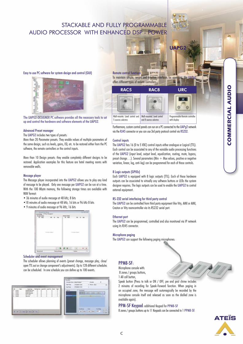
Remote control functionsTo maintain simple, secure and intuitive interfaces for operators, the UAPg2 offers different types of remote controllers:
Furthermore, custom control panels can run on a PC connected to the UAPg2 network via the RJ45 connector or you can use 3rd party protocol control via RS232.
Control inputsThe UAPG2 has 16 (0 to 5 VDC) control inputs either analogue or Logical (TTL). Each control can be associated to any of the variable audio processing functions of the UAPG2 (input level, output level, equalization, routing, mute, bypass, preset change…). Several parameters (Min + Max values, positive or negative variation, linear, log, anti-log) can be programmed for each of these controls.
8 Logic outputs (GPIOs)Each UAPG2 is equipped with 8 logic outputs (TTL). Each of those hardware outputs can be associated to virtually any software buttons or LEDs the system designer requires. The logic outputs can be used to enable the UAPG2 to control external equipment.
RS-232 serial interfacing for third party controlThe UAPG2 can be controlled from third party equipment like Vity, AMX or AMX, Creston or Vity roomcontroller via its RS232 serial port.
Ethernet portThe UAPG2 can be programmed, controlled and also monitored via IP network using its RJ45 connector.
Microphone pagingThe UAPG2 can support the following paging microphones:
PPM8-SF: Microphone console with: 8 zones / groups buttons,1 All call button,Speak button (Press to talk or ON / OFF, pre and post chime includes 2 minutes of recording for Speak-Forward function. When paging in an occupied zone, the message will automagically be recorded by the microphone console itself and released as soon as the dialled zone is available again).
PPM-SF Keypad: additional Keypad for PPM8-SF8 zones / groups buttons up to 11 Keypads can be connected to 1 PPM8-SF.
RAC5 RAC8 URC
Wall-mounte. Level control and 5 sources selectors
Wall-mounted. Level controland 8 sources selectors
Programmable Remote controller with display
STACKABLE AND FULLY PROGRAMMABLE AUDIO PROCESSOR WITH ENHANCED DSP - POWER
UAPG2

C
CO
MM
ER
CIA
L A
UD
IO
Te c h n i c a l s p e c i f i c a t i o n s :
Audio Inputs
Audio input impedance: 10 kOhms (symmetrical, screw terminal)Input sensitivity: 0 dB, -12dB, -24 dB,-40dB, -55 dB (software selection)Max input: +15 dBuBandwidth: 20 Hz to 20 kHzPhantom power soft config 48 VDC
Audio Outputs
Audio output impedance: 100 Ohms (symmetrical, screw terminal)Bandwidth 20 Hz to 20 kHzMax output +15 dBu.Total Harmonic Distortion < 0.03% , +0 dBu, 20~20 kHz, unity gain, 20 kHz BWS/N: (100 dB),( re+15 dBu), unity gain, 22 kHz BWS/N:(80 dB),( re+15 dBu),( 54 dB gain), 22 kHz BWDynamic range: (100 dB),( re+15 dBu), 22 kHz BW
Serial connectionsRS232 port: for ATEIS or third party equipment remote controlRS485 port: for Remote Controllers and Paging Microphones data controlRJ45 port: for PC control and system set up.
Digital LinkOne RJ45 TX to send data and audio to next deviceOne RJ45 Rx to receive data and audio from the previous device
Control outputs 8 TTL output 0 to 5 VDC, Contact NO and NC
Control inputs 16 TTL inputs or analogue inputs: 0 to 5 VDC (software selection)
Size and unitMetal unit 1 U 19” grey RAL 7016L x W x D: 431 x 44 x 240 mm
Power supply/Consumption
Power supply:AC: 100 to 240 VAC 50/60 HzDC: 21-28 VDCConsumption: 40 VA 10 VA in stand-by mode
STACKABLE AND FULLY PROGRAMMABLE AUDIO PROCESSOR WITH ENHANCED DSP - POWER
UAPG2
Junction BoxEasy chain-connection of UAPG2 peripherals (URC and PPM-SF), using standard CAT5 cables. Junction box is included with the PPM-SF.
UAPg2 Digital Link
If more inputs or outputs are required, it is possible to digitally link up to 12 UAPG2 (maximum distance between two UAPG2 is 10 meters). Through this link, you can share up to 16 channels at 48 kHz or 8 channels at 96 kHz sampling rate to the next device.
H
INT
EL
LIG
EN
T A
CO
US
TIC
SO
LU
TIO
NS
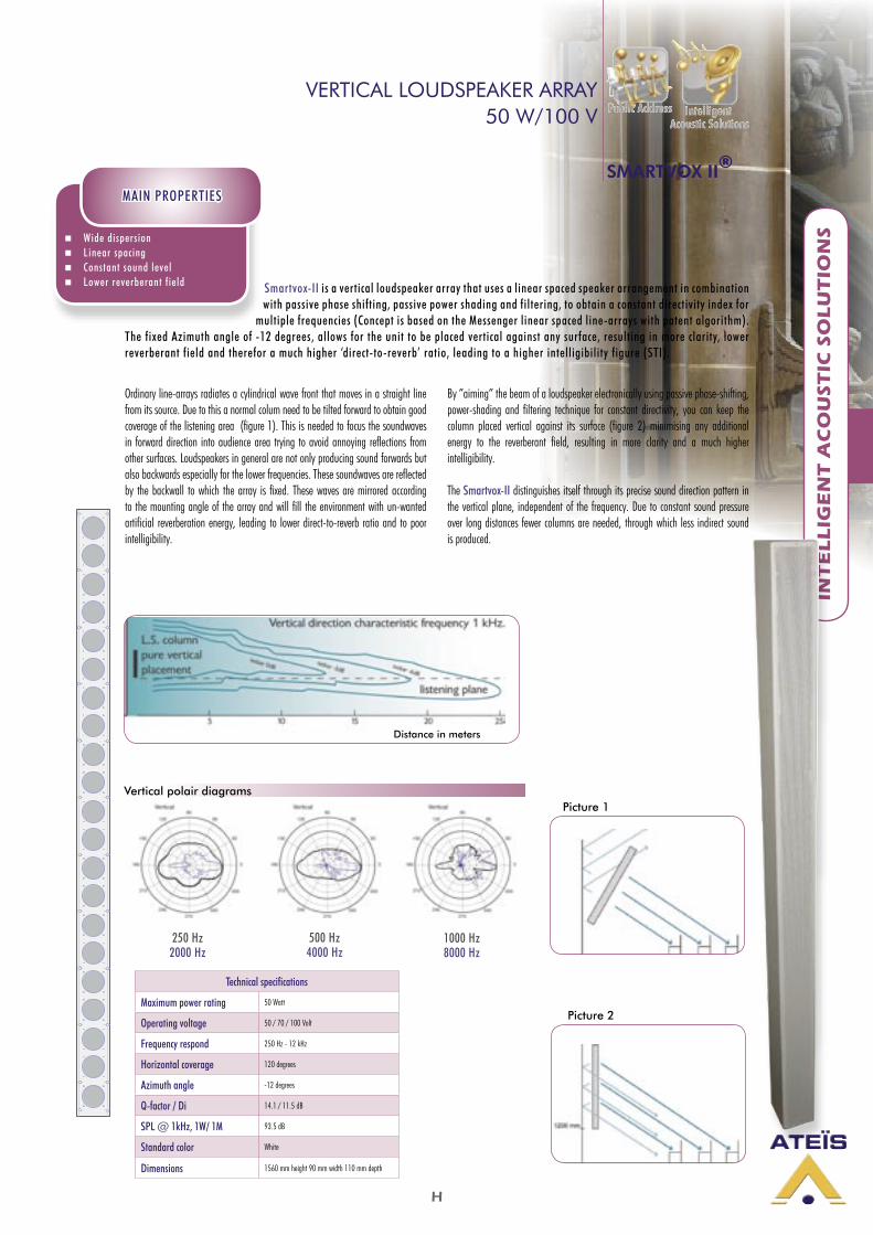
VERTICAL LOUDSPEAKER ARRAY50 W/100 V
Wide dispersion Linear spacing Constant sound level Lower reverberant field
MAIN PROPERTIES
1.2 m
Picture 2
Picture 1
250 Hz2000 Hz
500 Hz4000 Hz
1000 Hz8000 Hz
Vertical polair diagrams
SMARTVOX II®
Distance in meters
Technical specifications
Maximum power rating 50 Watt
Operating voltage 50 / 70 / 100 Volt
Frequency respond 250 Hz - 12 kHz
Horizontal coverage 120 degrees
Azimuth angle -12 degrees
Q-factor / Di 14.1 / 11.5 dB
SPL @ 1kHz, 1W/ 1M 93.5 dB
Standard color White
Dimensions 1560 mm height 90 mm width 110 mm depth
Smartvox-II is a vertical loudspeaker array that uses a linear spaced speaker arrangement in combination with passive phase shifting, passive power shading and filtering, to obtain a constant directivity index for
multiple frequencies (Concept is based on the Messenger linear spaced line-arrays with patent algorithm). The fixed Azimuth angle of -12 degrees, allows for the unit to be placed vertical against any surface, resulting in more clarity, lower reverberant field and therefor a much higher ‘direct-to-reverb’ ratio, leading to a higher intelligibility figure (STI).
Ordinary line-arrays radiates a cylindrical wave front that moves in a straight line from its source. Due to this a normal colum need to be tilted forward to obtain good coverage of the listening area (figure 1). This is needed to focus the soundwaves in forward direction into audience area trying to avoid annoying reflections from other surfaces. Loudspeakers in general are not only producing sound forwards but also backwards especially for the lower frequencies. These soundwaves are reflected by the backwall to which the array is fixed. These waves are mirrored according to the mounting angle of the array and will fill the environment with un-wanted artificial reverberation energy, leading to lower direct-to-reverb ratio and to poor intelligibility.
By ”aiming” the beam of a loudspeaker electronically using passive phase-shifting, power-shading and filtering technique for constant directivity, you can keep the column placed vertical against its surface (figure 2) minimising any additional energy to the reverberant field, resulting in more clarity and a much higher intelligibility.
The Smartvox-II distinguishes itself through its precise sound direction pattern in the vertical plane, independent of the frequency. Due to constant sound pressure over long distances fewer columns are needed, through which less indirect sound is produced.
INT
EL
LIG
EN
T A
CO
US
TIC
SO
LU
TIO
NS
D
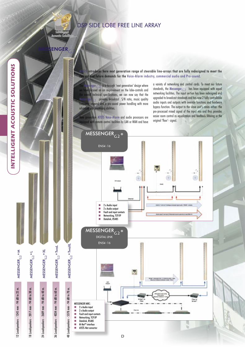
MESSENGERG2 ®DIGITAL LINK
EN54 -16
MESSENGER MRC: 2 x Audio input 2 x Audio output Fault and input contacts Networking, TCP/IP Datalink, RS485 M-NetTM interface ATEÏS-Net convertor
2 x Audio input 2 x Audio output Fault and input contacts Networking, TCP/IP Datalink, RS485
MESSENGERG2 ®
EN54 -16
12
Loud
spea
kers
- 13
45 m
m -
94 d
B to
25
m.
MES
SEN
GER
G2
® M
18
Loud
spea
kers
- 20
17 m
m -
94 d
B to
30
m.
MES
SEN
GER
G2
® L
24
Loud
spea
kers
- 26
89 m
m -
94 d
B to
40
m.
MES
SEN
GER
G2
® X
L
36
Loud
spea
kers
- 40
34 m
m -
94 d
B to
60
m.
MES
SEN
GER
G2
® T
woL
48
Loud
spea
kers
- 53
78 m
m -
94 d
B to
70
m.
MES
SEN
GER
G2
® T
woX
L
The MessengerG2 is a through ‘next generation’ design where we have focused on an improvement on the lobe-controls and the overall technical specifications, we can now say that the MessengerG2 provides broadcast S/N ratio, music quality frequency respond and a pro-sound power handling with more advanced pre-processing abilities.
New generation ATEÏS Voice-Alarm and audio processors are equipped with remote control facilities by LAN or WAN and have
a variety of networking and control cards. To meet our future standards, the MessengerG2 has been equipped with equal networking facilities. The input section has been redesigned and upgraded to broadcast standards and has now 2 fully controllable audio inputs and outputs with override functions and hardware bypass function. The output to the slave unit’s caries either the pre-processed mixed signal of the input mix and thus provides easier room control as equalization and feedback filtering or the original ‘floor’- signal.
MESSENGERG2
DSP SIDE LOBE FREE LINE ARRAY
ATEÏS introduces here next generation range of steerable line-arrays that are fully redesigned to meet the current and future demands for the Voice-Alarm industry, commercial audio and Pro-sound.
D
INT
EL
LIG
EN
T A
CO
US
TIC
SO
LU
TIO
NS
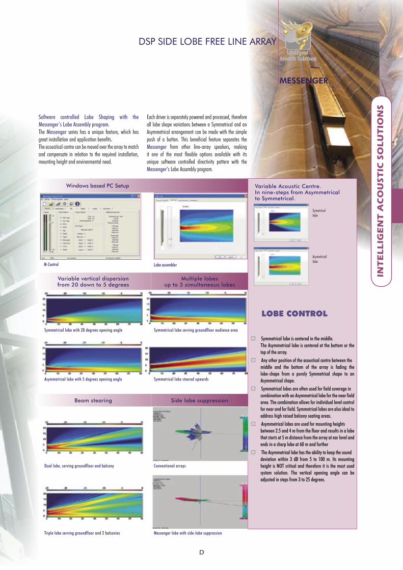
Variable Acoustic Centre. In nine-steps from Asymmetrical to Symmetrical.
Symetricallobe
Asymetricallobe
Symmetrical lobe is centered in the middle. The Asymmetrical lobe is centered at the bottom or the top of the array.
Any other position of the acoustical centre between themiddle and the bottom of the array is fading the lobe-shape from a purely Symmetrical shape to an Asymmetrical shape.
Symmetrical lobes are often used for field coverage incombination with an Asymmetrical lobe for the near field area. The combination allows for individual level control for near and for field. Symmetrical lobes are also ideal to address high raised balcony seating areas.
Asymmetrical lobes are used for mounting heightsbetween 2.5 and 4 m from the floor and results in a lobe that starts at 5 m distance from the array at ear level and ends in a sharp lobe at 60 m and further
The Asymmetrical lobe has the ability to keep the sounddeviation within 3 dB from 5 to 100 m. Its mounting height is NOT critical and therefore it is the most used system solution. The vertical opening angle can be adjusted in steps from 3 to 25 degrees.
LOBE CONTROL
Software controlled Lobe Shaping with the Messenger’s Lobe Assembly program.The Messenger series has a unique feature, which has great installation and application benefits. The acoustical centre can be moved over the array to match and compensate in relation to the required installation, mounting height and environmental need.
Each driver is separately powered and processed, therefore all lobe shape variations between a Symmetrical and an Asymmetrical arrangement can be made with the simple push of a button. This beneficial feature separates the Messenger from other line-array speakers, making it one of the most flexible options available with its unique software controlled directivity pattern with the Messenger’s Lobe Assembly program.
Windows based PC Setup
M-Control Lobe assembler
Variable vertical dispersionfrom 20 down to 5 degrees
Multiple lobesup to 3 simultaneous lobes
Symmetrical lobe with 20 degrees opening angle Symmetrical lobe serving groundfloor audience area
Asymmetrical lobe with 5 degrees opening angle Symmetrical lobe steered upwards
Beam stearing Side lobe suppression
Dual lobe, serving groundfloor and balcony Conventional arrays
Triple lobe serving groundfloor and 2 balconies Messenger lobe with side-lobe suppression
DSP SIDE LOBE FREE LINE ARRAY
MESSENGERG2
INT
EL
LIG
EN
T A
CO
US
TIC
SO
LU
TIO
NS
D
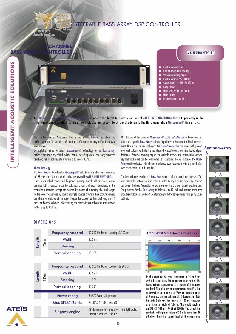
Controlled directivity. Low and Sub-Low steering. Variable opening angles. Controlled freq. 25 - 400 Hz. Signal decay, ± 1dB @ 100 m. Long throw. High SPL, 97 dB @ 100 m. High clarity. Effective size: 7 to 14 m.
MAIN PROPERTIES
8-CHANNEL BASS-ARRAY CONTROLLER
STEERABLE BASS-ARRAY DSP CONTROLLER
The combination of Messenger line arrays and a Bass-Array offers the perfect solution for speech and musical performance in any difficult acoustic environment. By applying the same patent Messenger® technology to the Bass-Array, makes it the first array of its kind that carries bass frequencies over long distances and keep the signal deviation within 2 dB over 100 m.
The technology:The Bass-Array is based on the Messenger® patent algorithm that was introduced in 1999 by Johan van der Werff and is now owned by ATEÏS INTERNATIONAL. Using a controlled power and frequency shading model, full directivity control and side-lobe suppression can be obtained. Upper and lower frequencies of this controlled directivity concept are defined by means of extending the total length for the lower frequencies by having multiple sources of which their acoustic centres are within ½ distance of the upper frequencies spaced. With a total length of 14 meter and only 8 cabinets, lobe steering and directivity control can be achievedown to 35 Hz up to 400 Hz.
With the use of the powerful Messenger® LOBE-ASSEMBLER software you can built and shape the Bass-Array-Lobe to fit perfectly in the acoustic difficult environ-ment. Use a dual or triple lobe and the Bass-Array-Lobe can cover both ground level and balcony with the highest directivity possible and with the lowest signal deviation. Variable opening angles for variable throws and symmetrical and/or asymmetrical lobes can be constructed. By changing the ½ distance, the Bass-Array can be adapted to fit with required cross-over frequencies with any midd-high tone array available in the market.
The bass cabinets used in the Bass-Array can be of any brand and any size. The lobe assembler software can be easily adapted to any size and brand. For this we can adapt the Lobe Assembler software to meet the 3rd part brand specifications. The processor for the Bass-Array is delivered as 19-inch rack mount frame that provides analogue as well as AES interfacing with the self-powered third party Bass-cabinets.
∆
λ
∆
∆
∆
∆
∆
∆
λambda-Array
λ
LOBE ASSEMBLE for BASS-ARRAY
In this example we have constructed a 14 m Array with 8 bass-cabinets. The ∆-spacing is set to 2 m. The lowest cabinet is positioned at a height of 4 m above ear level. The lobe has an asymmetrical base-FIR that is centred at speaker no. 3. With an opening angle of 7 degrees and an azimuth of -2 degrees, this lobe has only 2 db variation from 5 to 100 m, measured at a listening height of 1.80 m. This would result in an SPL @ 100 m of 94dB at 120 Hz. The signal that reach the ceiling at a height of 30 m is more than 10 dB down from the signal level at listening plane.
Leng
th
700 c
m
Frequency respond 50-340 Hz, Delta – spacing ∆ 100 cm
Width 43.6 cm
Steering ± 15°
Vertical opening 10 - 25
Leng
th
1400
cm
Frequency respond 35-200 Hz, Delta - spacing: ∆ 200 cm
Width 43.6 cm
Steering ± 10°
Vertical opening 5°-25°
Power rating 8 x 500 Watt Self powered
Max SPL@125 Hz 95 dB@ 5-100 m ±2 dB
3rd party engine15” long excursion cone driver, ferrofluid cooledCabinet resonance <45 Hz
D I M E N S I O N S
The Bass-Array Controller or Lambda Array is one of the latest technical creations of ATEÏS INTERNATIONAL that fits perfectly in the ‘Intelligent audio solution’ range of products and has proven to be a real add-on to the third generation Messenger® line arrays.

FF
INT
EL
LIG
EN
T A
CO
US
TIC
SO
LU
TIO
NS
Traffic tunnels. Industrial purpose. Long throw. High SPL. High intelligibility. Special purpose design. Durable.
MAIN PROPERTIES
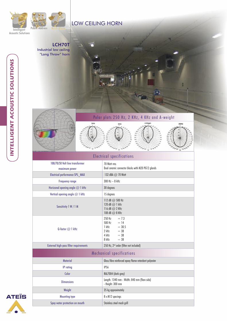
LCH70TIndustrial low ceiling “Long Throw” horn
LOW CEILING HORN
LCH70TIndustrial low ceiling “Long Throw” horn
λambda-Array
The LCH70T is made of reinforced fibre/epoxy and equipped with a strong and powerful 2” compression driver, capable of producing a fabulous 117 dB. The shape and structure allow for use in highly demanding environments like traffic tunnels and car parks. Also train tubes that need to be addressed during voice-evacuations are typical examples where the LCH70T would fit perfectly.
Due to its dimensions, its throw can reach from 40 up to 70 m, reducing ampli-fiers and delay lines when compared to conventional distributed sound systems for tunnels. This will bring the total costs down and due to a lower number of horns, it will bring the Q-factor up and so the intelligibility of the overall evacuation system.
The LCH70T has an extended frequency range that runs up to 8 kHz allowing for high-fidelity speech messages in situation where the acoustics are limited and therefore the demands on the soundsystem high. Highly directional horns will result in a bigger in between, repeating distance, reduced soundpoints and so reduced number of amplifiers and delay-lines and so, resulting in a better overall price performance.
The LCH70T is a typical symmetrical exponential horn (= where the horn length is exponentially related to the horn area) that uses the mounting surface as wave guide. This way a “half cell” construction can be used, reducing its mouth height that is important when used in environment with height restrictions. Once in the proper band pass region for a given size, an exponential horn presents a fairly consistent acoustical load to its driver. This helps both output level and evenness of frequency response, and is what makes this horn design simple and effective.
The LCH70T should be fixed against a large and flat surface that acts as a waveguide and mirror.. The small horizontal opening angle of only 30 degrees guarantees that the sound will stay unaffected by lateral distortion and so will increases the in-between distance of the horns.
M e c h a n i c a l d r a w i n g w i t h 8 x 1 2 m m f i x a t i o n h o l e s
a n d v e r t i c a l - r i b s f o r e x t r a s t a b i l i t y
The LCH70T is one of the latest products from ATEÏS INTERNATIONAL and especial ly designed for the voice -evacuation market. The LCH70T is a typical exponential horn that is designed to be used in placed with restr ic ted cei l ing heights and where far throws are requested.
Key features: - Boundary effect, low-spill - Increased repeating distance - Long-horn, straight patterns - 2-inch compression driver - High-SPL - High-directivity
Background-noise: 90 dBa SPL: 104 dBa @ 20 m
F
INT
EL
LIG
EN
T A
CO
US
TIC
SO
LU
TIO
NS
F
E l e c t r i c a l s p e c i f i c a t i o n s100/70/50 Volt line transformer
maximum power70 Watt rmsDual ceramic connector blocks with M20 PG12 glands
Electrical performance SPL_MAX 132 dBA @ 70 Watt
Frequency range 300 Hz – 8 kHz
Horizonal opening angle @ 1 kHz 30 degrees
Vertical opening angle @ 1 kHz 15 degrees
Sensitivity 1 W / 1 M
112 dB @ 500 Hz120 dB @ 1 kHz116 dB @ 2 KHz108 dB @ 8 KHz
Q-factor @ 1 kHz
250 Hz = 7.3500 Hz = 141 kHz = 30.52 kHz = 384 kHz = 388 kHz = 38
External high-pass filter requirements 250 Hz, 2nd order (filter not included)
M e c h a n i c a l s p e c i f i c a t i o n s
Material Glass fibre reinforced epoxy flame-retardant polyester
IP rating IP56
Color RAL7004 (dark-grey)
DimensionsLength: 1340 mm - Width: 840 mm (flare side) - Height: 300 mm
Weight 35 kg approximately
Mounting type 8 x M12 spacings
Spay water protection on mouth Stainless steel mesh grill
LOW CEILING HORN
LCH70TIndustrial low ceiling
“Long Throw” horn
INT
EL
LIG
EN
T A
CO
US
TIC
SO
LU
TIO
NS
Po l a r p l o t s 2 5 0 H z , 2 K H z , 4 K H z a n d A - w e i g h t
G
CO
UN
TE
R I
NT
ER
CO
M
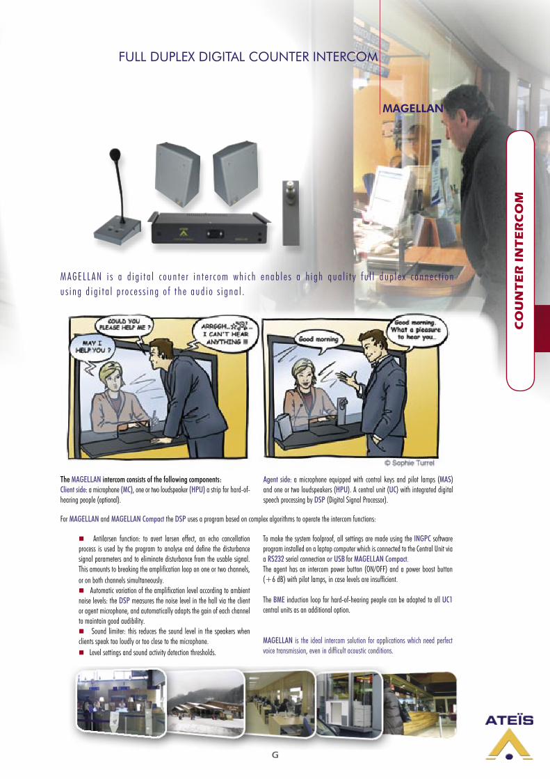
FULL DUPLEX DIGITAL COUNTER INTERCOM
M A G E L L A N i s a d i g i t a l c o u n t e r i n t e r c o m w h i c h e n a b l e s a h i g h q u a l i t y f u l l d u p l e x c o n n e c t i o n u s i n g d i g i t a l p r o c e s s i n g o f t h e a u d i o s i g n a l .
Antilarsen function: to avert larsen effect, an echo cancellation process is used by the program to analyse and define the disturbance signal parameters and to eliminate disturbance from the usable signal. This amounts to breaking the amplification loop on one or two channels, or on both channels simultaneously. Automatic variation of the amplification level according to ambient noise levels: the DSP measures the noise level in the hall via the client or agent microphone, and automatically adapts the gain of each channel to maintain good audibility. Sound limiter: this reduces the sound level in the speakers when clients speak too loudly or too close to the microphone. Level settings and sound activity detection thresholds.
To make the system foolproof, all settings are made using the INGPC software program installed on a laptop computer which is connected to the Central Unit via a RS232 serial connection or USB for MAGELLAN Compact.The agent has an intercom power button (ON/OFF) and a power boost button (+6 dB) with pilot lamps, in case levels are insufficient.
The BME induction loop for hard-of-hearing people can be adapted to all UC1 central units as an additional option.
MAGELLAN is the ideal intercom solution for applications which need perfect voice transmission, even in difficult acoustic conditions.
The MAGELLAN intercom consists of the following components:Client side: a microphone (MC), one or two loudspeaker (HPU) a strip for hard-of-hearing people (optional).
Agent side: a microphone equipped with control keys and pilot lamps (MAS) and one or two loudspeakers (HPU). A central unit (UC) with integrated digital speech processing by DSP (Digital Signal Processor).
MAGELLAN
For MAGELLAN and MAGELLAN Compact the DSP uses a program based on complex algorithms to operate the intercom functions:
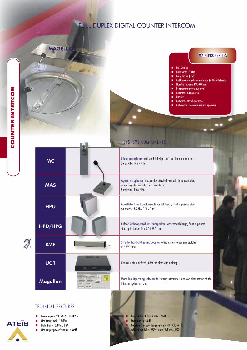
G
CO
UN
TE
R I
NT
ER
CO
MC
OU
NT
ER
IN
TE
RC
OM
MC Client microphone: anti-vandal design, uni-directional electret cell. Sensitivity: 14 mv / Pa.
MAS Agent microphone: fitted on flex attached to a built-in support plate comprising the two intercom contol keys. Sensitivity: 8 mv / Pa.
HPU Agent/client loudspeaker: anti-vandal design, front in painted steel, gain factor: 85 dB / 1 W / 1 m.
HPD/HPG Left or Right Agent/client loudspeaker : anti-vandal design, front in painted steel, gain factor: 85 dB / 1 W / 1 m.
BME Strip for hard-of-hearing people: coiling on ferrite bar encapsulated in a PVC tube.
UC1 Central unit: unit fixed under the plate with a clamp.
Magellan Magellan Operating software for setting parameters and complete setting of the intercom system on-site.
MAGELLAN
S Y S T E M E C O M P O N E N T S
T E C H N I C A L F E A T U R E S
Power supply: 230 VAC/50 Hz/0.2 A Max input level: -18 dBu Distortion:<0.4% to 1 W Max output power/channel: 4 Weff.
Bandwidth: 50 Hz - 7 KHz ±3 dB Dynamics: >58 dB Conditions for use: temperature of -10 °C to + °C, relative humidity: 100%, water-tightness: IP2
Full Duplex Bandwidth: 8 KHz Fully digital (DSP) Antilarsen via echo cancellation (without filtering) Nominal power: 4 W/8 Ohms Programmable output level Automatic gain control Limiter Automatic stand-by-mode Anti-vandal microphones and speakers
MAIN PROPERTIES
FULL DUPLEX DIGITAL COUNTER INTERCOM
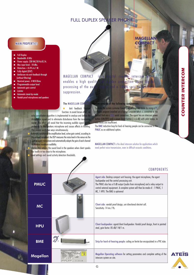
G
CO
UN
TE
R I
NT
ER
CO
M
Anti feedback function function: to avoid larsen effect, an
echo cancellation algorithm is implemented to analyse and define the disturbance signal and to eliminate disturbance from the incomming signal. This effect will avoid that the incoming audible signal will be picked-up by the speakers microphone and causes effects in howling. This process works two ways simultaneously.
Automatic variation of the amplification level, active gain control, according to the ambient noiselevel: the DSP measures the noise level in the venue via the client or agent microphone and automatically adapts the gain of each channel to maintain maximum audibility.
Limiter: this reduces the sound level in the speakers when client speaks too loudly or too close to the microphone.
Level settings and sound activity detection thresholds.
To make the system customer friendly, all settings are made by using a PC software program installed on a laptop computer which is connected to the Central Unit via a USB serial connection. The agent has an intercom power button (ON/OFF) and a power boost button (+6 dB) with pilot lamps, in case levels are insufficient. The BME induction loop for hard-of-hearing people can be connected to the PMUC as an additional option.
MAGELLAN COMPACT is the ideal intercom solution for applications which need perfect voice transmission, even in difficult acoustic conditions.
M A G E L L A N C O M PA C T i s a d i g i t a l c o u n t e r i n t e r c o m w h i c h e n a b l e s a h i g h q u a l i t y f u l l d u p l e x c o n n e c t i o n u s i n g d i g i t a l p r o c e s s i n g o f t h e a u d i o s i g n a l a n d a 1 0 0 % s e c u r e d f e e d b a c k s u p p r e s s i o n .
Full Duplex Bandwidth: 8 KHz Power supply: 230 VAC/50 Hz/0.2 A. Max input level: -18 dBu. Distortion:<0.4% to 1 W. Fully digital (DSP) Antilarsen via anti-feedback through (without filtering) Nominal power: 4 W/8 Ohms Programmable output level Automatic gain control Limiter Automatic stand-by-mode Vandal-proof microphones and speakers
MAIN PROPERTIES
MAGELLAN COMPACT
PMUC
Agent side: Desktop compact unit housing: the agent microphone, the agent loudspeaker and the central processing unit.The PMUC also has a 0 dB output (audio from microphone) and a relay output to control external equipment. A complete system will then be made of : 1 PMUC, 1 MC, 1 HPU. The BME is optionnal
MC Client side: vandal proof design, uni-directional electret cell. Sensitivity: 14 mv / Pa.
HPU Client loudspeaker: agent/client loudspeaker: Vandal proof design, front in painted steel, gain factor: 85 dB/1 W/1 m.
BME Strip for hard-of-hearing people: coiling on ferrite bar encapsulated in a PVC tube.
Magellan Magellan Operating software for setting parameters and complete setting of the intercom system on-site.
C O M P O N E N T S
FULL DUPLEX SPEAKER PHONE
The MAGELLAN COMPACT intercom consists of the following components:

G
CO
UN
TE
R I
NT
ER
CO
MC
OU
NT
ER
IN
TE
RC
OM
MAGELLAN VOCAL POINT
T h e A T E Ï S ‘ Vo c a l - Po i n t ’ i s t h e f i r s t d e s k - t o p v o i c e - a n d i n d u c t i o n l o o p a m p l i f i e r t h a t s h o u l d n o t b e m i s s e d o n y o u r c o u n t e r d e s k . I t s e r v e s p e o p l e t h a t h a v e a h e a r i n g d i s a b i l i t y a n d o r h a v e a h e a r i n g a i d t h a t c a n r e c e i v e i n d u c t i o n l o o p t r a n s m i s s i o n s . T h e s e d a y s w i t h t h e o p e n d e s k c o u n t e r s , d i s c r e t i o n b e c o m e s m o r e a n d m o r e a n i s s u e a n d a r a i s i n g v o i c e f r o m t h e s e r v i c e -a g e n t d o e s n o t a t t r i b u t e t o t h e d e s c r i t i o n . T h e Vo c a l - Po i n t h e l p s t o b r i n g t h e 2 0 d B s i g n a l a m p l i f i c a t i o n a b o v e t h e n o r m a l h e a r i n g l e v e l f o r p e o p l e w i t h a h e a r i n g d i s a b i l i t y a n d a t t h e s a m e t i m e m a i n t a i n s m a x i m u m d i s c r e t i o n d u e t o t h e c u s t o m e r s h a n d h e l d s p e a k e r p h o n e a n d i n d u c t i o n a n t e n n a .
The customer can either listen using the induction antenna through his or her ’s pick-up coil in the hearing aid, or can lift the handset that acts like a speakerphone.
Due to the long history of developing and manufacturing of electronics, ATEÏS knows best what to create when customers come to us with a need. ATEÏS has looked closely to the needs of their customers and used their long experience on counter-intercom to put this into the design of the ‘Vocal-Point’. Specialized in product industrialization, pick-up microphones with integrated functions like
auto-gain and peak-limiting, the ‘Vocal-Point’ will guarantee for durability and ease of use. The microphone in the desk-unit is carefully constructed to avoid any vibrations transmitted from the desk to the desk-unit. The induction antenna is complying with IEC 118-1.
IGME Agent side: Desktop unit that has an omnidirectional microphone and an on/off switch. It is linked to an induction antenna that can be mounted underneath a desk.
Combiné HP
Customer side: Handset that acts like a handheld speakerphone and contains a full rang high quality loudspeaker and amplifier.
BME Strip for hard-of-hearing people: coiling on ferrite bar encapsulated in a PVC tube.
C O M P O N E N T S
FULL DUPLEX DIGITAL SPEAKER PHONE

ATEÏS reserve the right to change specifications without notice
Graph
ic De
sign :
Help
rod.co
m - P
hotog
raphy
: ATE
ÏS - H
élène
BRISS
ET
: Im
prime
rie de
s Eau
x Clai
res -
Echir
olles.
India: Ashok Tower, Mubai Congnjzant Technology Solutions Mubai
Edelweis Hotel, Mubai Cricket Academy, Mumbai.
Middle East:
Abu Dhabi Church American school, Doha Jebal Ali, Dubai Festifal City Mall, Dubai Global Village Mall, Dubai
Jumeirah Beach Hotel, Dubai Ottoman Palace Hotel, Dubai
Palm Jumeraih, Dubai Ski Dubai, Dubai.
Denmark:
The Crowne Plaza i Part, Copenhagen Crowne Plaza Hotel Copenhagen ( Copenhagen Towers ) Opening nov 2009 H&M Main Store Amagertorv, Copenhagen Føtex Food Hasseris, Aalborg Føtex Food Guldsmedegade, Aarhus DS Centrals-tock, Aarhus H&M Nørrebro, Copenhagen H&M, Odense
Panum Institute, Copenhagen.
Germany:
Deutsche Oper, Berlin Bayrische Staatskanzlei, München n Kongresscenter, Würzburg Fraunhofer Umsicht, Oberhausen
Heeresflugplatz, Roth Handels-Lehr-Anstalt, Bruchsal
Deutsches Luft- und Raumfahrtzentrum, Oberpfaffenhofen
Hauptbahnhof Darmstadt, Darmstadt Campus Westend, Johann Wolfgang Goethe-Universität, Frankfurt am Main.
UK:
Royal festival Hall Royal Halls, Harrogate Victoria sq, Bel-fast Tallagh centre, Dublin Snow hill BASF Chemical plant, Midlands Lewisham Civic centre Eltham Leisure centreBahaus store, Iceland PFI Schools, Scotland St Mirrens Stadium White city Station Derby Shopping Centre Derby Theatre.
Belgium:
North Galaxy, Brussels European Parliament, Brussels Exxon Mobile, Brussels Grain cake Bakery, Ath Galery Theater Arenberg, Brussels Imagimons, Mons Carrefour, Belgium
Bierset Airport, Liège Axa Bank, Brussels Cynagogue de Forest, Brussels Swift La hulpe, Brussels Fire station, Brussels Fire station, Liège Musée des beaux arts, Mons
Hospital, Mouscron Galerie Anspach, Brussels Kempinski Hotel, Bruges.
Suitzerland:
M1 and M2 subway lines,Lausanne Universität, Sankt Gallen
Shopping mall and football stadia, Neuchâtel Hôpitaux Univer-sitaires, Genève Pictet bank, Geneva Theater, Sankt Gallen
Tramway maintenance center, Basel Notre-Dame church, Vevey Airport, Zürich.
Portugal:
Batalha Cathedral Stella Maris Pavillion Guarda Cathedral
Amadora Chruch.
Hong Kong:
Hong Kong Airport, Hong Kong.
Norway:
Bjørnholt VG skole, Oslo HIBU (Highschool), Drammen
Gjøvik Olympic Arena, Fjellhallen, Gjøvik Med vennlig, Hilsen.
Slovakia:
SAMSUNG LCD factory, Voderady HANSOL LCD, Voderady
BANG JOO Electronics, Šurany JMT SK, Hlohovec.
France:
Rolland Garros stadium, Paris Air france Roissy headquarter, Paris France Stadium, Paris St Exupery airport, Lyon
Department Hall, Marseille Pharo cultural center, Marseille
Communal headquarter, Marseille Borely Hippodrome, Mar-seille Congress Hall, Dijon Auditorium, Dijon Mediacenter, Montpellier Zenith, Pau Futuroscope, Poitiers Merignac Airport, Bordeaux Palais des sports, Grenoble Department Hall, Bastia Congress Hall, Toulon Zenith, Toulouse Airport St Martin, Antilles Zara shops, Paris, Lyon, Bordeaux, Marseille
St Microelectronics Plant, Grenoble Caisse d’epargne, bank Lyon RATP line 11 symphonie, Paris RER Nation/Etoile station, Paris SNCF railway stations, Metz, Besançon, Aix les Bains, Lyon Perrache, Frejus-St Raphael, Charleville Mézières, Mulhouse, Montluçon, Le Havre, Brive, Voiron, Villefranche sur saône, Ouest Lyonnais, Sarrebourg, Chambery, Brest, Morlaix, St Brieuc, Guingamp, Valence ville, Hazebrouk, Roanne, Paris Nord, Paris Est, Nîmes, Marseille St Charles, Monaco, Antibes, Angers, Lyon Part Dieu, Nancy stations TGV railway station East
Commercial Mall “Grand Littoral”, Marseille Nice côte d’azur T2, Airport Footbal stadium, Grenoble TRAM TRAIN, Aulnay
Bondy Grimaldi forum, Monaco.
South Africa:
ABSA 160 Main ABSA 170 Main Road JHB Edgewood College Fairlands Office Development Foschini Stanley Lewis Center Kendal Power Station IDC Building Sandton Melrose Arch New Car Park Parc Du Cap Momentum HQ-Centurion Nedbank BOE Spar Distribution Colloseum
Africa House Cavendish Connect SA NAVY ABSA 270 Main
UCT Woman Res.
Portugal:
Conference Rooms in the Hotel & Casino of “Chaves” City of Chaves “Colombo” Shopping, Lisbon Conference Room of “Carcavelos” local hall, Village of Carcavelos Conference Room of “Academia Militar” School, Lisbon City Hall swimming pool of “Covilhã”, City of Covilhã “LUZ” Stadium systems improvement (Benfica Football Club Stadium), Lisbon.
Italy:
Battistero del Duomo, Pisa Santuario Madonna dei Miracoli, Casalbordino, Chieti Santa Maria della Scala in San Fedele, Milano Duomo di Gambarare, Mira, Venezia.
REFERENCES
ATEÏS International S.A.
[email protected]://www.ateis-international.com
Chemin du Dévent Z.I. des Larges Pièces A1024 EcublensSwitzerland Tél : +41 21 881 25 10 Fax: +41 21 881 25 09
Public Address - Voice Alarm - Commercial Audio - Intelligent Acoustic Solutions - Counter Intercom
Catalogue2009
[email protected]://www.ateis-international.com
Chemin du Dévent Z.I. des Larges Pièces A
1024 EcublensSwitzerland
Tél : +41 21 881 25 10 Fax: +41 21 881 25 09