high speed asic design
TRANSCRIPT

8/3/2019 High Speed ASIC Design
http://slidepdf.com/reader/full/high-speed-asic-design 1/23
High Speed ASIC Design of
Complex
Multiplier Using VedicMathematics
Hardware implementation of NikhiIam Sutra

8/3/2019 High Speed ASIC Design
http://slidepdf.com/reader/full/high-speed-asic-design 2/23
INTRODUCTION V edic Mathematics is the ancient methodology of
Indian mathematics which has a unique technique of calculations based on 16 sutras(formulae).
It is used for calculating complicated arithmeticaloperations,and to a extent ,executing them mentally.
On account of those formulae, the partial productsand sums are generated in one step which reduces thecarry propagation from LSB to MSB.
The implementation of the V edic mathematics andtheir application to the complex multiplier ensuresubstantial reduction of propagation delay incomparison with DA based architecture and paralleladder based implementation.

8/3/2019 High Speed ASIC Design
http://slidepdf.com/reader/full/high-speed-asic-design 3/23
The functionality of these circuits was checked andperformance parameters like propagation delay
and dynamic power consumption were calculated by spice spectra using standard 90nm CMOStechnology.
The propagation delay of the resulting(16,16)X(16,16) complex multiplier is only 4ns andconsume 6.5mW power as compared to the normalmultiplier which takes 11 ns.
We achieve almost 25% improvement in speedfrom earlier reported complex multipliers

8/3/2019 High Speed ASIC Design
http://slidepdf.com/reader/full/high-speed-asic-design 4/23
VEDIC MULTIPLICATION
The proposed V edic multiplier is based on the V edic multiplication formulae NIKHILAMSUTRA.
These Sutras have been traditionally used for the
multiplication of two numbers in the decimalnumber system.
In this work, we apply the same ideas to the binary
number system to make the proposed algorithmcompatible with the digital hardware.
V edic multiplication based on NIKHILAM SUTRA as discussed below :-

8/3/2019 High Speed ASIC Design
http://slidepdf.com/reader/full/high-speed-asic-design 5/23
Nikhilam Sutra
Nikhilam Sutra literally means ³all from 9 and lastfrom 10´.
Although it is applicable to all cases of multiplicationit is more efficient when the numbers involved arelarge. Since it finds out the compliment of the large
number from its nearest base to perform themultiplication operation on it, larger is the originalnumber, lesser the complexity of the multiplication.
We first illustrate this Sutra by considering the
multiplication of two decimal numbers (96 * 93) wherethe chosen base is 100 which is nearest to and greaterthan both these two numbers.
We should take the power of 10 as base.

8/3/2019 High Speed ASIC Design
http://slidepdf.com/reader/full/high-speed-asic-design 6/23
Multiplication Using NikhilamSutra

8/3/2019 High Speed ASIC Design
http://slidepdf.com/reader/full/high-speed-asic-design 7/23
The right hand side (RHS) of the productcan be obtained by simply multiplying thenumbers of the Column 2 (7*4 = 28).
The left hand side (LHS) of the product can be f ound by cross subtracting thesecond number of Column 2 from the firstnumber of Column 1 or vice versa, i.e., 96 -
7 = 89 or 93 - 4 = 89. The final result isobtained by concatenating RHS and LHS(Answer = 8928)
8/3/2019 High Speed ASIC Design
http://slidepdf.com/reader/full/high-speed-asic-design 8/23
COMPLEX MULTIPLIER USING VEDIC
MATHEMATICS
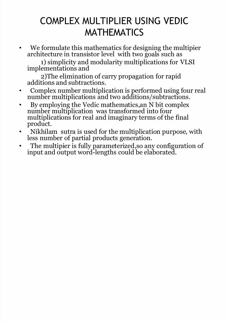
We formulate this mathematics for designing the multipierarchitecture in transistor level with two goals such as
1) simplicity and modularity multiplications for V LSIimplementations and
2)The elimination of carry propagation for rapidadditions and subtractions. Complex number multiplication is performed using four real
number multiplications and two additions/subtractions. By employing the V edic mathematics,an N bit complex
number multiplication was transformed into four
multiplications for real and imaginary terms of the finalproduct. Nikhilam sutra is used for the multiplication purpose, with
less number of partial products generation. The multipier is fully parameterized,so any configuration of
input and output word-lengths could be elaborated.

8/3/2019 High Speed ASIC Design
http://slidepdf.com/reader/full/high-speed-asic-design 9/23
HARDWARE IMPLEMENTATION OF
EXPONENT DETERMINENT

8/3/2019 High Speed ASIC Design
http://slidepdf.com/reader/full/high-speed-asic-design 10/23
PIPO(Parallel input Parallel Output) Shifter:
For the non-zero number shifting operation is executed usingPIPO shift registers.
Each bit is shifted to left ones till µ1¶ is obtained at the MSB.
The number of select lines is chosen as per the binary representation of the number(N-1)10
µSHIFT¶ pin is assigned in PIPO shifter to check whether thenumber is to be shifted or not.
To initialize the operation, SHIFT pin is initialized to low.

8/3/2019 High Speed ASIC Design
http://slidepdf.com/reader/full/high-speed-asic-design 11/23
Decrementer:
A decrementer has bee integrated to follow the maximum power of the radix.
For an N bit number, the value (N-1)10 is fed to the input of decrementer.
The decrementer is decremented based on a control signal which isgenerated by the searched results. If search bit is µ0¶ then the controlsignal becomes low then decrementer starts decrementing the input value. If search bit is µ1¶ then the control signal becomes high and the
decrementer stops further decrementing and shifter also stopsshifting operation.
The output of the decrementer shows the integer part(exponent) of the number.

8/3/2019 High Speed ASIC Design
http://slidepdf.com/reader/full/high-speed-asic-design 12/23
Using exponent determinent, the integer part or exponent of thenumber can be obtained by the maximunm power of the radix-2.
Input X is given to the PIPO shifter. The shifter shifts the input by 1 bitto the left.
With the help of select lines, MSB is selected and fed to thedecrementer. This acts as the control signal to the decrementer.
For an N bit number, the value (N-1)10 is fed to the input of decrementer.
If the MSB is µ0¶, control signal becomes low then decrementer startsdecrementing the input value. If the MSB is µ1¶ then the control signal becomes high and the decrementer stops further decrementing andshifter also stops shifting operation.
Output is obtained from the decrementer, which is the integerpart(exponent) of the input X.
WORKING :

8/3/2019 High Speed ASIC Design
http://slidepdf.com/reader/full/high-speed-asic-design 13/23

8/3/2019 High Speed ASIC Design
http://slidepdf.com/reader/full/high-speed-asic-design 14/23
The working of the RSU can be explained as per
the
Block diagram :- First the input X that is of N bits is given to
the exponent determinant which gives the
exponent of X.eg:- X is 17 i.e. 2^4+1
exponent is 4.
The exponent is fed to two blocks respectively
a) The adder and the shifter combination which calculates the value 2^n. The adderadds a carry to the maximum value of the
exponent and the shifter generates 2^n.

8/3/2019 High Speed ASIC Design
http://slidepdf.com/reader/full/high-speed-asic-design 15/23
b) The shifter block which shifts theexponent
to find 2^(n-1). The output of these two blocks is fed to the
mean determinant which determines themean
(2^(n-1)+2^n)/2. Next this output is fed to the comparator
which compares the output of the meandeterminant and the input X and gives a result0 or 1.
if X>A ; Output 1.if X<A ; Output 0.
Where A is the output of the mean determinant.

8/3/2019 High Speed ASIC Design
http://slidepdf.com/reader/full/high-speed-asic-design 16/23
In the end there is a mux which selects therequired radix depending upon the output
of the comparator.if Output is 1; radix is 2^n.
if Output is 0; radix is 2^(n-1).
Using these basic building blocks, the RSUand
the exponent determinator, the hardware
Implementation of NIKHILAM SUTRA can be
Carried out.

8/3/2019 High Speed ASIC Design
http://slidepdf.com/reader/full/high-speed-asic-design 17/23
Representation
We represent the numbersto be multiplied in theform as mentioned earlier
but with base number being powers of 2.
The RSU output gives theradix of the number thusrepresented as µk 1/2 ¶ and
the residue is represented by µz1/2¶ where 1/2 indicateseither input 1 or 2respectively.

8/3/2019 High Speed ASIC Design
http://slidepdf.com/reader/full/high-speed-asic-design 18/23
Equations

8/3/2019 High Speed ASIC Design
http://slidepdf.com/reader/full/high-speed-asic-design 19/23
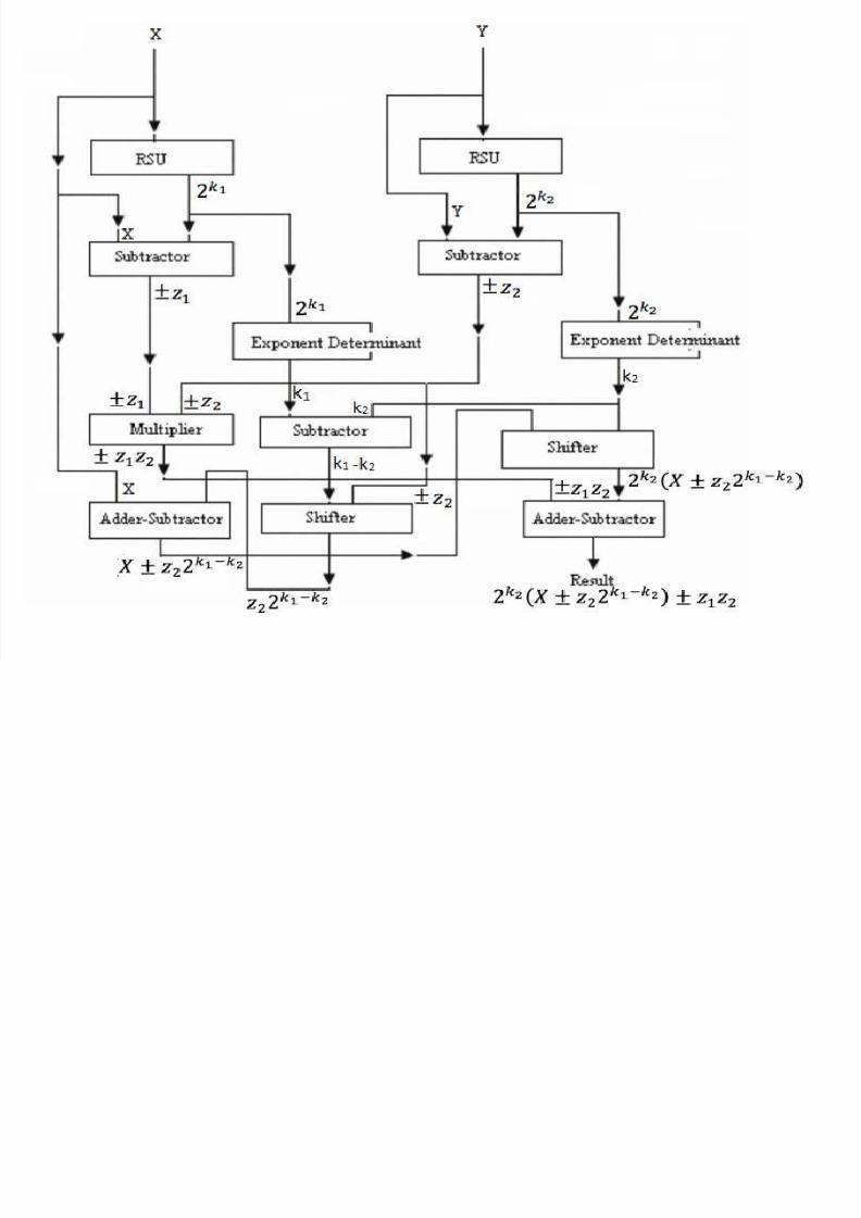
Implementation The block diagram of the implementation using
the equation obtained is as shown

8/3/2019 High Speed ASIC Design
http://slidepdf.com/reader/full/high-speed-asic-design 20/23
The hardware implementation logic
The input is given to the RSU to determine the nearestradix in the powers of 2.
The RSU output is given to the exponent determinator togive the exponent of the input number.
This value is subtracted from the input using asubtractor that gives the residue of the input.
The process is repeated for the other input as well.
Both the residues are multiplied using a multiplier to
obtain the highlighted portion of the equation.
Note: We also have the value of the exponent.

8/3/2019 High Speed ASIC Design
http://slidepdf.com/reader/full/high-speed-asic-design 21/23
The exponents of both inputs are subtracted usinga subtractor.
The residue of 2nd input is as input to the shifterand the count is given as the output of thesubtractor
Note: Each time a number is left shifted , the numberdoubles itself
The output of shifter obtained is added/subtracted by the 1st input by the adder/subtractor to obtain
the highlighted portion of the equation.

8/3/2019 High Speed ASIC Design
http://slidepdf.com/reader/full/high-speed-asic-design 22/23
The output thus obtained is given as input to a
shifter with the count being the exponent value of 2nd input.
The product thus obtained, is given to anadder/subtractor which adds/subtracts to get the
final output given by the highlighted equation.
8/3/2019 High Speed ASIC Design
http://slidepdf.com/reader/full/high-speed-asic-design 23/23