high speed controller - msu · the pin assignment of the external ... 4 driver installation high...
TRANSCRIPT

LaVisionWe count on Photons
Product-Manual
High Speed Controller
Item-Number(s): 1108074, 1108075, 1108076

Product-Manual forDaVis 8.1
LaVision GmbH, Anna-Vandenhoeck-Ring 19, D-37081 Göttingen
Produced by LaVision GmbH, Göttingen
Printed in Germany
Göttingen, January 17, 2012
Document name: 1006382_HighSpeedController_D81.pdf

Contents
Contents
1 Safety Precautions 5
1.1 Laser Safety . . . . . . . . . . . . . . . . . . . . . . . . . . . . . 5
1.2 Seizures Warning . . . . . . . . . . . . . . . . . . . . . . . . . . 6
1.3 Camera / Image Intensifier Safety . . . . . . . . . . . . . . . . . 7
2 Introduction 9
3 General Description 11
3.1 HSC versions . . . . . . . . . . . . . . . . . . . . . . . . . . . . . 11
3.2 HSC Sequenzer I/O Specifications . . . . . . . . . . . . . . . . . 12
3.3 HSC Terminals . . . . . . . . . . . . . . . . . . . . . . . . . . . . 12
3.3.1 HSC Trigger Terminal . . . . . . . . . . . . . . . . . . . . . 12
3.3.2 HSC Trigger Adapter . . . . . . . . . . . . . . . . . . . . . 12
3.3.3 Wiring . . . . . . . . . . . . . . . . . . . . . . . . . . . . . 15
4 Driver Installation 17
4.1 Driver location . . . . . . . . . . . . . . . . . . . . . . . . . . . . 17
4.2 Installing for the first time . . . . . . . . . . . . . . . . . . . . . 17
4.3 Verify the driver installation . . . . . . . . . . . . . . . . . . . . 21
4.4 Updating the driver . . . . . . . . . . . . . . . . . . . . . . . . . 22
4.5 Uninstall the driver . . . . . . . . . . . . . . . . . . . . . . . . . 24
5 DaVis Hardware Setup 25
5.1 HSC . . . . . . . . . . . . . . . . . . . . . . . . . . . . . . . . . . 25
6 Customer Service 27
6.1 Order and Dongle Number . . . . . . . . . . . . . . . . . . . . . 27
6.2 Customer Settings . . . . . . . . . . . . . . . . . . . . . . . . . . 28
6.3 Log.txt . . . . . . . . . . . . . . . . . . . . . . . . . . . . . . . . 29
6.4 Export data set for support . . . . . . . . . . . . . . . . . . . . . 30
6.5 Camera Activity Logging . . . . . . . . . . . . . . . . . . . . . . 32
6.6 Shipment of defective items . . . . . . . . . . . . . . . . . . . . 34
3

Contents
4
1 Safety Precautions
Before working with your LaVision system we recommend to read the
following safety precautions. Observing these instructions helps to avoid
danger, to reduce repair costs and downtimes and to increase the reliability
and life of your LaVision system.
1.1 Laser Safety
If a laser1 is integrated in your system it is important that every person
working with it has fully read and understood these safety precautions and
the laser manual of the specific laser.
Lasers included in LaVision systems may belong to CLASS 4 laser de-
vices, which are capable of emitting levels of both visible and invisible ra-
diation that can cause damage to the eyes and skin. It is absolutely neces-
sary that protective eyewear with a sufficiently high optical density is worn
at any time when operating the laser. The goggles must protect against all
wavelengths that can be emitted, including harmonics. See your Laser´s
manual for further details.
Class 4 laser beams are by definition a safety and fire hazard. The use of
controls, adjustments or performance of procedures other than those spec-
ified in the LaVision manual and laser manual may result in hazardous
radiation exposure.
AVOID EYE AND SKIN EXPOSURE TO DIRECT OR SCATTERED RADIATION.
FOLLOW THE INSTRUCTIONS YOU CAN FIND IN THE CORRESPONDING LASER
MANUAL FOR PROPER INSTALLATION AND SAFE OPERATION. USE PROTEC-
TIVE EYE WEAR ALL THE TIME WHEN OPERATING THE LASER.
Important instructions for safe laser handling:
• Before operating the laser contact your laser safety officer.
1In the following ‘laser’ means any kind of laser, in particular Nd:YAG- and dye laser as
well as Optical Parametric Oscillators at any wave-length and output-energy.
5
1 Safety Precautions
• Read and understand the instruction manual of the particular type of
laser. Take special care with respect to laser emission, high voltage
and hazardous gases if in use.
• Declare a controlled access area for laser operation. Limit access to
trained people. Never operate the laser in a room where laser light
can escape through windows or doors. If possible, cover beam paths
to avoid obstacles getting into the beam.
• Provide adequate and proper laser safety-goggles to all persons
present who may be exposed to laser light. The selection of the gog-
gles depends on the energy and the wavelength of the laser beam
as well as the operation conditions. Check the Laser´s manual for a
detailed description.
• While working with lasers do not wear reflective jewelry like watches
and rings, as these might cause accidental hazardous reflections.
• Avoid looking at the output beam, even diffuse reflections can be dan-
gerous.
• Operate the laser at the lowest beam intensity possible.
• Avoid blocking the output beam or reflections with any part of the
body. Use beam dumps to avoid reflections from the target.
• Wear clothes and gloves which cover arms and hands to avoid skin
damage when handling in the optical path. Especially UV-radiation
can cause skin cancer.
1.2 Seizures Warning
WARNING: HEALTH HAZARD! STROBE LIGHTING COULD TRIGGER SEIZURES
Some people (about 1 in 4000) may have seizures or blackouts triggered
by flashing lights or patterns. This may occur when viewing stroboscopic
lights or objects illuminated by such devices, even if a seizure has never
been previously experienced. Anyone who has had a seizure, loss of aware-
ness, or other symptoms linked to an epileptic condition should consult a
doctor before operating systems which include flashing lights, strobe lights,
or a pulsed or modulated laser.
Stop operating the system immediately and consult a doctor if you have
one of the following symptoms:
6

1.3 Camera / Image Intensifier Safety
• convulsions, eye or muscle twitching, loss of awareness, altered vi-
sion, involuntary movements, disorientation
To reduce the likelyhood of a seizure when operating a system:
• Do not look directly at flashing light sources or on illuminated objects,
e.g. into a strobe light or a flashing LED panel.
• Operate the system in a well-lit room.
• Take frequent breaks in normally illuminated areas.
1.3 Camera / Image Intensifier Safety
The camera integrated in your system is based on a CCD (Charge Coupled
Device) or CMOS (Complementary Metal-Oxide Semiconductor) sensor with
high resolution and high sensitivity. Optionally your system is equipped
with a built-in or external image intensifier.
A LASER BEAM FOCUSED ON THE CHIP OR INTENSIFIER, EITHER DIRECTLY
OR BY REFLECTION, CAN CAUSE PERMANENT DAMAGE TO THE CHIP OR IN-
TENSIFIER. ANY LASER POWERFUL ENOUGH TO PRODUCE LOCALIZED HEAT-
ING AT THE SURFACE OF THE CHIP OR INTENSIFIER WILL CAUSE DAMAGE
EVEN WHEN THE CAMERA OR INTENSIFIER POWER IS OFF. A CHIP OR IN-
TENSIFIER DAMAGED BY LASER LIGHT IS NOT COVERED BY ITS WARRANTY.
Important instructions for safe camera handling:
• Fully read and understand the instruction manual of the specific type
of camera.
• Put the protection cap on the camera lens whenever you do not take
images, especially when the laser beam is adjusted. Switching off the
camera / image intensifier does not protect the chip from damage by
laser light.
• Use full resolution of the sensor and always read out the complete
chip to have control of the intensity on all areas of the sensor.
• Make sure that no parts of the image are saturated, i.e. the intensity
is below maximum gray level (< 4095 counts for a 12 bit camera,
< 65535 counts for a 16 bit camera, ...).
7

1 Safety Precautions
• Start measurements with the lowest laser power and a small aperture
of the camera lens.
• Increase laser power step by step and check the intensity on the cor-
responding image. Make sure that the sensor does not run into satu-
ration.
• Bright parts in the experiment, like reflections on walls or big parti-
cles, will limit the maximum laser power. Modify the optical arrange-
ment of your setup in order to remove bright reflections from the
camera image.
8

2 Introduction
The completely software controlled HighSpeed Controller(HSC) is an em-
bedded system for generation of complex patterns of pulses (sequences)
with highly accurate timing on multiple outputs (up to 16 independent
channels) as used for the synchronization ofLaVision’s Intelligent Imag-
ing Systems. The HSC is a stand alone USB device. The pulse width and
the interval between pulses are programmed automatically by theDaVissoftware according to the application, the connected hardware (laser, cam-
era, etc.) and the user settings in the dialog boxes insideDaVis.
The microprocessor controlled timing sequence can be started by an ex-
ternal trigger or constantly generated by an internal frequency generator
(e.g. at a specified laser repetition rate).
The entire functionality is embedded into an FPGA (Field Programmable
Gate Array) which allows in system updates and upgrades.
9

2 Introduction
10

3 General Description
3.1 HSC versions
Version Features Typical applications
BASIC Free choice of recording rate. Imaging or
(art. 1108074) HS IRO support. StrainMaster systems
Two synchronization signals.
STANDARD BASIC plus:
(art. 1108075) PIV double frame recording. PIV, LIF, SprayMaster,
Internal or external image trigger.
Supports HS laser and ADC.
ROTARY DECODER STANDARD plus: EngineMaster, Turbines
(art. 1108076) hardware rotary decoder for
precise phase trigger by encoder
signal readout.
Full cycle ADC support
11
3 General Description
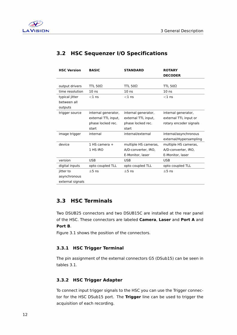
3.2 HSC Sequenzer I/O Specifications
HSC Version BASIC STANDARD ROTARY
DECODER
output drivers TTL 50Ω TTL 50Ω TTL 50Ω
time resolution 10 ns 10 ns 10 ns
typical jitter <1 ns <1 ns <1 ns
between all
outputs
trigger source internal generator, internal generator, internal generator,
external TTL input, external TTL input, external TTL input or
phase locked rec. phase locked rec. rotary encoder signals
start start
image trigger internal internal/external internal/asynchronous
external/Hypersampling
device 1 HS camera + multiple HS cameras, multiple HS cameras,
1 HS IRO A/D-converter, IRO, A/D-converter, IRO,
E-Monitor, laser E-Monitor, laser
version USB USB USB
digital inputs opto coupled TLL opto coupled TLL opto coupled TLL
jitter to ±5 ns ±5 ns ±5 ns
asynchronous
external signals
3.3 HSC Terminals
Two DSUB25 connectors and two DSUB15C are installed at the rear panel
of the HSC. These connectors are labeled Camera, Laser and Port A and
Port B.
Figure 3.1 shows the position of the connectors.
3.3.1 HSC Trigger Terminal
The pin assignment of the external connectors G5 (DSub15) can be seen in
tables 3.1.
3.3.2 HSC Trigger Adapter
To connect input trigger signals to the HSC you can use the Trigger connec-
tor for the HSC DSub15 port. The Trigger line can be used to trigger the
acquisition of each recording.
12

3.3 HSC Terminals
HighSpeed Controller
Figure 3.1: Front and rear panel of the HSC.
Pin Name Pin Name Pin Name
1 Seq. Trigger 6 n.c. 11 GND
2 Seq. Arming 7 Pio IN1 High 12 GND
3 Start 8 Pio IN2 High 13 GND
4 Increment 9 GND 14 Pio IN1 Low
5 input (unused) 10 GND 15 Pio IN2 Low
Table 3.1: Pin assignment of the HSC G5 (DSub15) port.
13
3 General Description
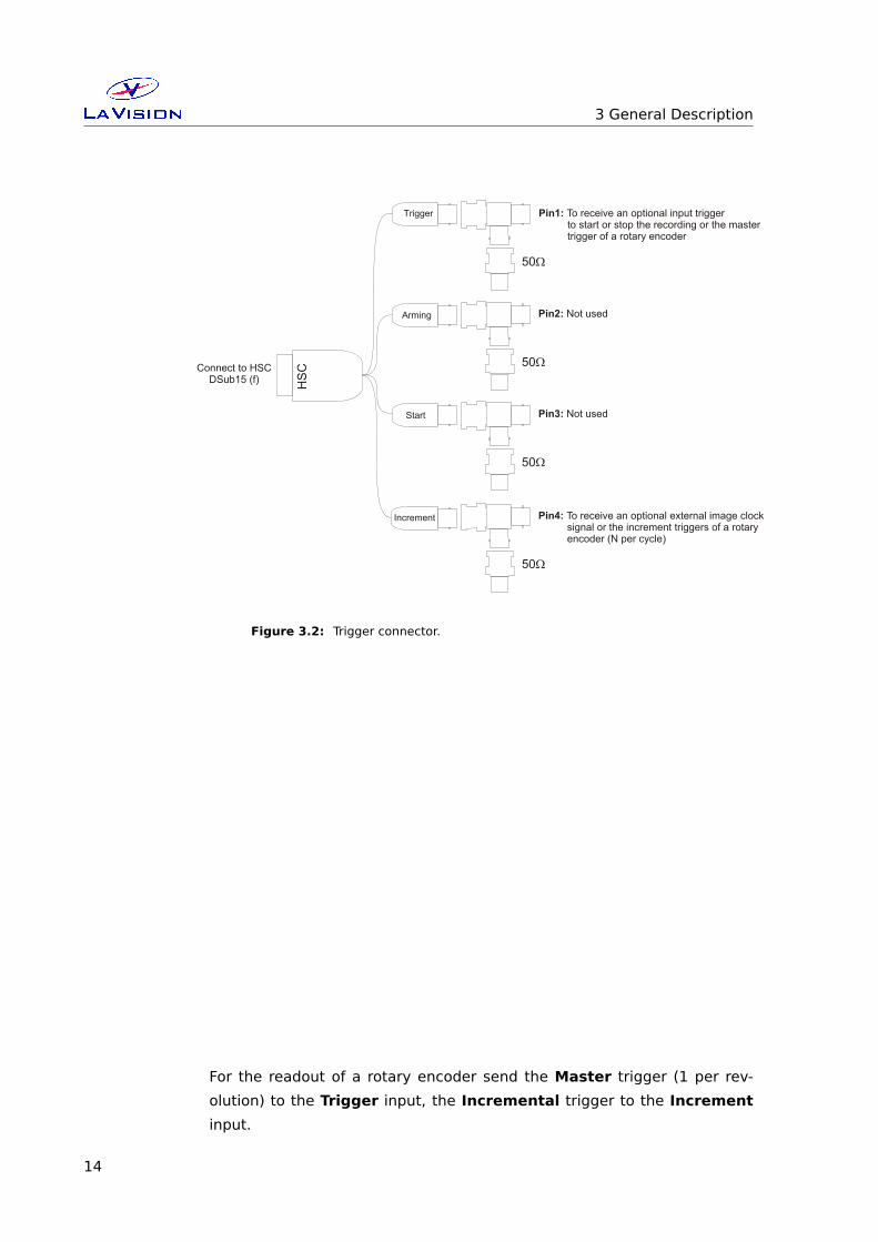
HS
C
Pin1: To receive an optional input trigger to start or stop the recording or the master trigger of a rotary encoder
Connect to HSCDSub15 (f)
Arming
Start
Increment
50W
Trigger
Pin3: Not used
50W
Pin2: Not used
50W
Pin4: To receive an optional external image clock signal or the increment triggers of a rotary encoder (N per cycle)
50W
Figure 3.2: Trigger connector.
For the readout of a rotary encoder send the Master trigger (1 per rev-
olution) to the Trigger input, the Incremental trigger to the Increment
input.
14

3.3 HSC Terminals
3.3.3 Wiring
You have to connect the following cables to get the HSC Controller to work:
• Connect the Highspeed Controller (HSC) to a USB port of the PC
• Connect the Power supply of the HSC to the mainpower
• Please notice that there are 2 power switches, one on the HSC con-
troller and the other one on the external power supply
15

3 General Description
16
4 Driver Installation
4.1 Driver location
If you have aDaVis version installed on your PC the driver can be found
in the ’∼DaVis/driver/PlugAndPlay/LaVision Generic’ directory. Otherwise
the driver for the external HSC can be found on your DaVis installation
CD in the ’/drivers/LaVision Generic’ folder.
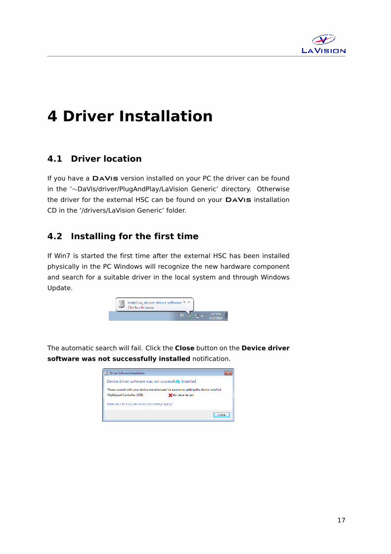
4.2 Installing for the first time
If Win7 is started the first time after the external HSC has been installed
physically in the PC Windows will recognize the new hardware component
and search for a suitable driver in the local system and through Windows
Update.
The automatic search will fail. Click the Close button on the Device driver
software was not successfully installed notification.
17

4 Driver Installation
Open the Computer Management Console in Win7 via Start button,
right mouse click on the Computer entry and selecting the Manage op-
tion. Select the Device Manager under the System Tools entry.
Under Other Devices you will find an High Speed Controller entry.
18

4.2 Installing for the first time
Use right mouse click on the Other Devices > ProgrammableTimingU-
nit v9 entry and select the Update Driver Software... option.
On the How do you want to search for driver software question select
the Browse my computer for driver software option.
19
4 Driver Installation
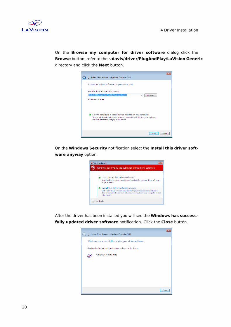
On the Browse my computer for driver software dialog click the
Browse button, refer to the∼davis/driver/PlugAndPlay/LaVision Generic
directory and click the Next button.
On theWindows Security notification select the Install this driver soft-
ware anyway option.
After the driver has been installed you will see theWindows has success-
fully updated driver software notification. Click the Close button.
20

4.3 Verify the driver installation
After restart of the PC you will find a Programmable Timing Unit, ver-
sion 9 (USB) entry under LaVision devices in the Windows Device Man-
ager.
4.3 Verify the driver installation
To make sure that the driver has been installed properly and to get an in-
formation on the exact driver version that has been installed please check
the diver information in the Windows Device Manager.
Use right mouse button on the Programmable Timing Unit, version 9
(USB) entry and select the Properties option.
On the driver card you should find the version no. 2.6.0.0.
21

4 Driver Installation
4.4 Updating the driver
In order to update the driver make sure that the new driver files are avail-
able locally. In this case we assume that the new files are available in the
∼davis/driver/PlugAndPlay/LaVision Generic directory.
Open the Windows Device Manager, select the Programmable Timing
Unit, version 9 (USB) entry under LaVision devices and use right mouse
click to select the Update Driver Software... option.
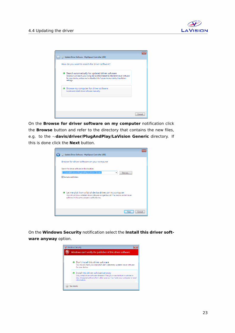
On the How do you want to search the driver software question select
the Browse my computer for driver software option.
22
4.4 Updating the driver
On the Browse for driver software on my computer notification click
the Browse button and refer to the directory that contains the new files,
e.g. to the ∼davis/driver/PlugAndPlay/LaVision Generic directory. If
this is done click the Next button.
On theWindows Security notification select the Install this driver soft-
ware anyway option.
23

4 Driver Installation
After the driver has been updated you will see theWindows has success-
fully updated driver software notification. Click the Close button.
4.5 Uninstall the driver
In order to uninstall the HSC driver open the Windows Device Manager,
select the High Speed Controller entry under LaVision devices and use
right mouse click to select the Uninstall option.
24

5 DaVis Hardware Setup
The settings in theHardware Setup dialog are entered byLaVision ap-
plication specialists during production or installation of your system. These
values should not be changed by the end user. Changing parameters may
cause a malfunction of the system.
To be able to control the camera on remote byDaVis it needs to be added
as device to theDaVis Hardware Setup dialog. Additionally the camera
needs to be provided with trigger signals that are synchronized to other
devices, e.g. an external trigger from the experiment or a trigger signal to
a light source for illumination. Therefore a camera in a LaVision system
is usually delivered with a High Speed Controller (HSC).
You can open the Hardware Setup dialog after start of the DaVis soft-
ware if you login as Expert User and click on the Setup icon.
5.1 HSC
If the HSC is already installed in the hardware setup you should find a High
Speed Controller in the device list as a sub-device under the Recording
entry.
25
5DaVis Hardware Setup
If this item is not present in the device list click on the Devices item to
highlight this and use the Add icon to select the HighSpeed Controller
from the list of available hardware.
The HSC can be ordered with different functionalities (e.g. with a rotary
decoder feature), depending on the installed firmware different features
are available on the corresponding file card in the hardware setup.
After all settings have been done use the the Initialize button for initial-
ization and use the Close button to return to the Project Manager dialog.
26
6 Customer Service
If you have a technical problem or questions regarding hardware or soft-
ware which is not adequately addressed in the documentation please con-
tact your local representative or LaVision service directly.
In order to speed up your request please include following information:
• The order number of your system (see section 6.1).
• The number of the used dongle (see section 6.1).
• A short description of the problem.
• Your customer settings file (see section 6.2).
• A log.txt if you have a reproducible software problem (see sec-
tion 6.3).
• An information on the used operating system and service pack.
You can contact service at LaVision GmbH by:
email: [email protected]
phone +49 551 9004 229Alternatively you may submit your problem using the service request inter-
face on the LaVision homepage under the URL www.lavision.com.
6.1 Order and Dongle Number
To be able to find information on the delivered hardware components and
customer details in the database your order number is required. This num-
ber can be found in theDaVis/Help/Aboutmenu or on the originalDaVisinstallation CD (see Fig. 6.1).
In the About DaVis dialog you find the order number in the 3rd line.
The five digits behind the leading X are the order number followed by the
DaVis version and the release date.
The dongle number is required to exclude license problems. This number
is is written on the hardware key. The number of the used dongle can also
be found using the DaVis/Help/About menu and on theDaVis CD.
27

6 Customer Service
order #
dongle #
Figure 6.1: Order no. inDaVis/Help and on installation CD.
Please include the order number and the dongle number in your service
requests.
6.2 Customer Settings
To be able to reproduce your problem it could be essential to know the
exact hardware setup and software parameter in DaVis. All currently
used parameter can be extracted using the DaVis/Help/Create service
file for LaVision Support menu.
After you have selected this the system will write back all values for the
relevant variables to an lsf-file. This procedure will take a while indicated
by a Busy dialog. The lsf-file will also contain the current settings of the
hardware setup, acquisition setup and processing operation lists.
The lsf-file will be written automatically to a davis/service subdirectory.
The name contains the order number and dongle number that is ex-
tracted from your software (#ordernumber_donglenumber.lsf). Send this
28
6.3 Log.txt
lsf-file as attachment to the description of you problem by email to ser-
6.3 Log.txt
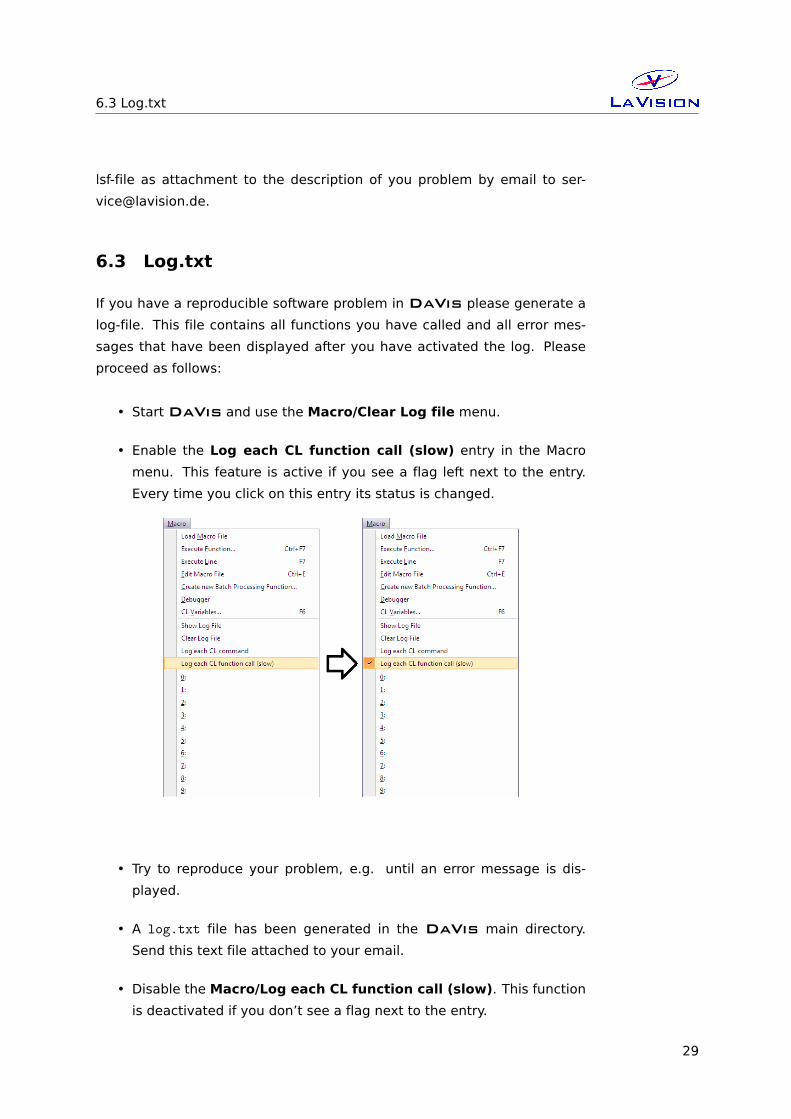
If you have a reproducible software problem in DaVis please generate a
log-file. This file contains all functions you have called and all error mes-
sages that have been displayed after you have activated the log. Please
proceed as follows:
• StartDaVis and use the Macro/Clear Log file menu.
• Enable the Log each CL function call (slow) entry in the Macro
menu. This feature is active if you see a flag left next to the entry.
Every time you click on this entry its status is changed.
• Try to reproduce your problem, e.g. until an error message is dis-
played.
• A log.txt file has been generated in the DaVis main directory.
Send this text file attached to your email.
• Disable the Macro/Log each CL function call (slow). This function
is deactivated if you don’t see a flag next to the entry.
29
6 Customer Service
6.4 Export data set for support
Some problems can only be reproduced on images that contain particular
information or artifacts. For error analysis it can be necessary to provide
exemplary data that needs to be extracted from the corresponding project.
Depending on the project type, number of used cameras and error the cor-
responding calibration and derivative data can be required as well.
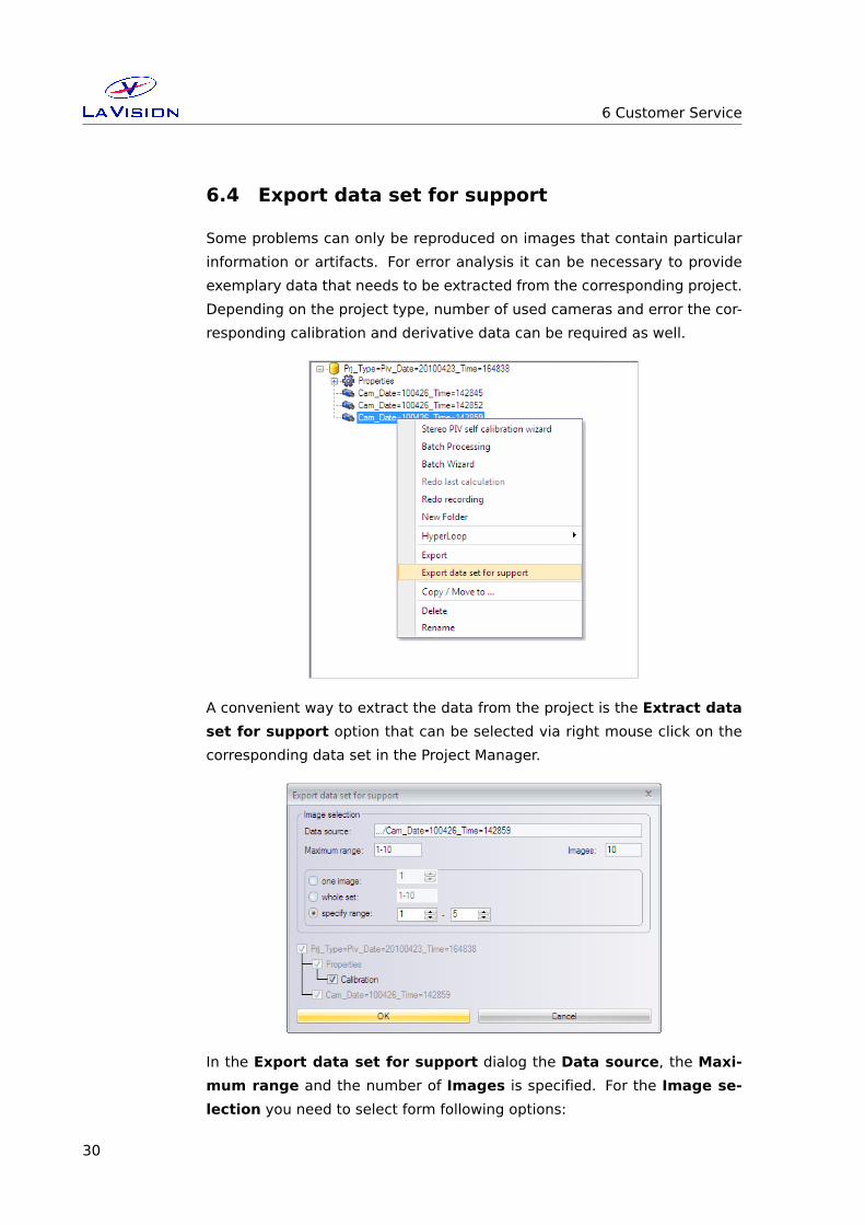
A convenient way to extract the data from the project is the Extract data
set for support option that can be selected via right mouse click on the
corresponding data set in the Project Manager.
In the Export data set for support dialog the Data source, the Maxi-
mum range and the number of Images is specified. For the Image se-
lection you need to select form following options:
30
6.4 Export data set for support
one image: This will extract one image only. You need to select the num-
ber of the image.
whole set: This will extract the complete data set. Please note that de-
pending on the number of images the resulting zip-file will be very
large.
specify range: This will extract the specified range. You need to select
minimum and maximum image number.
In addition you may activate the Calibration option and the corresponding
cameras. This will make sure that the calibration for these camera will be
included.
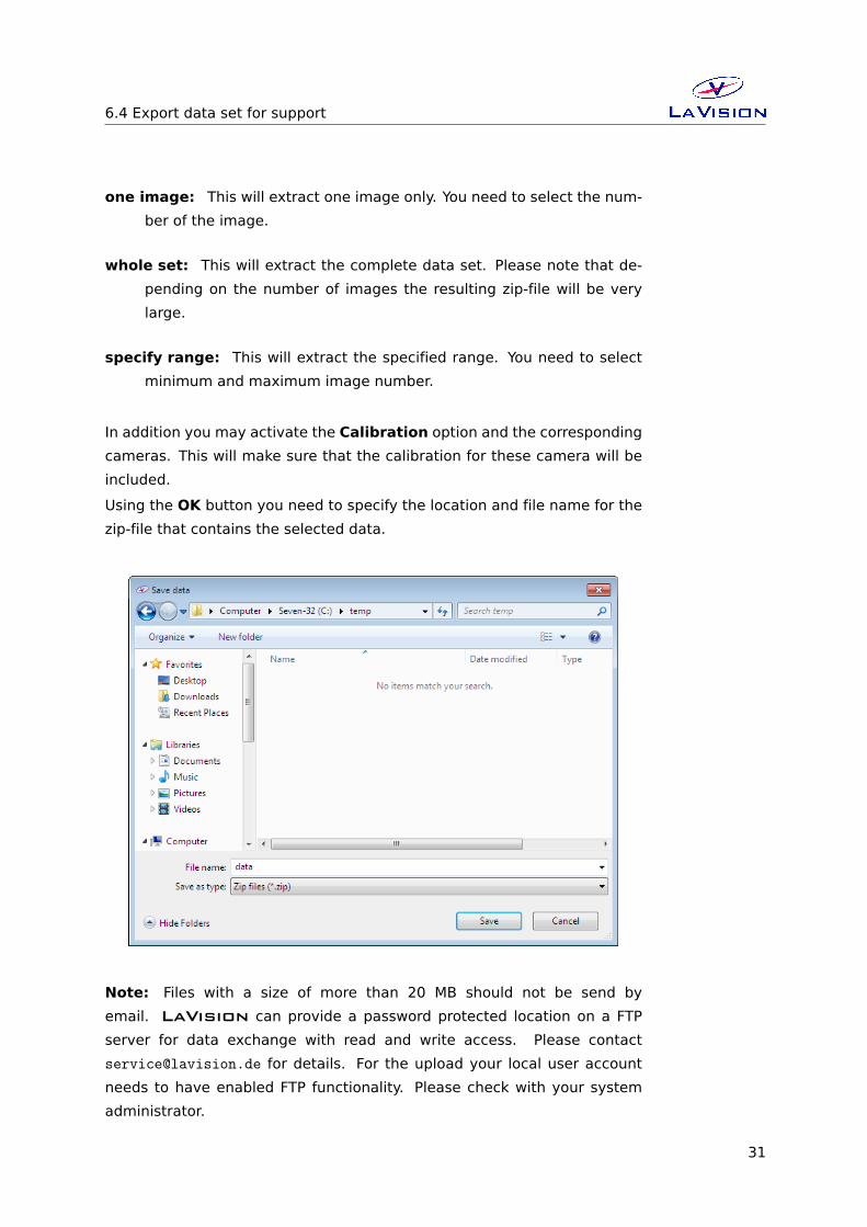
Using the OK button you need to specify the location and file name for the
zip-file that contains the selected data.
Note: Files with a size of more than 20 MB should not be send by
email. LaVision can provide a password protected location on a FTP
server for data exchange with read and write access. Please contact
[email protected] for details. For the upload your local user account
needs to have enabled FTP functionality. Please check with your system
administrator.
31

6 Customer Service
6.5 Camera Activity Logging
The camera support libraries (camera DLLs) used byDaVis have a built-
in logging function which might be useful for camera activity monitoring
and debugging. If you experience problems with camera behavior and con-
tact LaVision support, you may be asked to generate a log file during
camera operation and send it by email.
You can use the camera activity logging by choosing the appropriate item in
the DaVis Help menus. Open the following modal dialog window which
serves for starting and stopping the logging function, specifying logging
options and viewing the resulting log output. If you create a lsf-service file
after camera logging (see 6.2), the camera log data will be included.
In the top line of the dialog the Current logging status is displayed. If
this is not the ’OFF’ status, a number is displayed. Using the following ra-
dio buttons you can choose if you want to Log each CL function call +
programmed output, i.e. the complete communication betweenDaVisand the camera DLL, or to Log only programmed output (PrintLog).
Programmed output lines are the result of calls to the ’PrintLog’ function
inside the DLL or, fromDaVis, results of a CL function call like DevSetStr-
Par(DEV_CAMERA_1, CAMPAR_DEBUG, ’output string’). If you choose Log
each DLL function call, each Get() and Set() function call from DaVisto the DLL is logged together with the value of the parameter passed re-
spectively the result returned by the DLL.
Using the four checkboxes you can specify the output format and writing
mode:
Show execution times (differences): If this option is checked, each
output line is preceded by the time passed since the preceding output
line (microseconds).
32
6.5 Camera Activity Logging
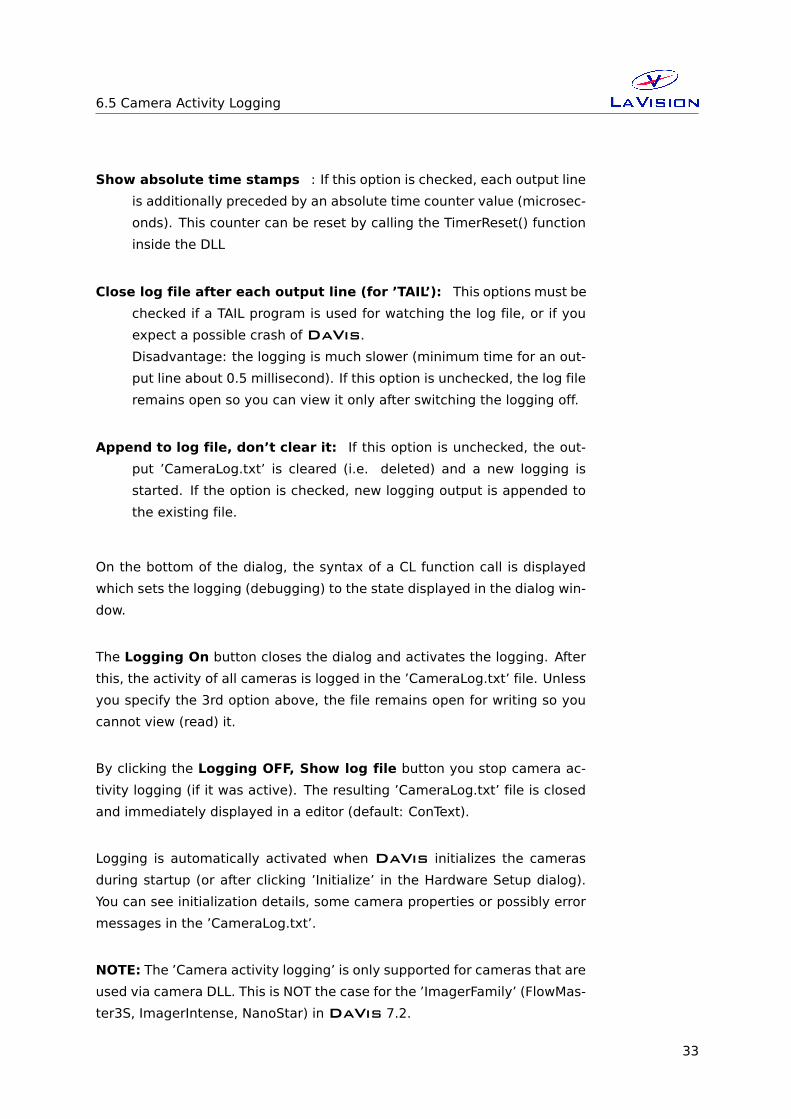
Show absolute time stamps : If this option is checked, each output line
is additionally preceded by an absolute time counter value (microsec-
onds). This counter can be reset by calling the TimerReset() function
inside the DLL
Close log file after each output line (for ’TAIL’): This options must be
checked if a TAIL program is used for watching the log file, or if you
expect a possible crash ofDaVis.Disadvantage: the logging is much slower (minimum time for an out-
put line about 0.5 millisecond). If this option is unchecked, the log file
remains open so you can view it only after switching the logging off.
Append to log file, don’t clear it: If this option is unchecked, the out-
put ’CameraLog.txt’ is cleared (i.e. deleted) and a new logging is
started. If the option is checked, new logging output is appended to
the existing file.
On the bottom of the dialog, the syntax of a CL function call is displayed
which sets the logging (debugging) to the state displayed in the dialog win-
dow.
The Logging On button closes the dialog and activates the logging. After
this, the activity of all cameras is logged in the ’CameraLog.txt’ file. Unless
you specify the 3rd option above, the file remains open for writing so you
cannot view (read) it.
By clicking the Logging OFF, Show log file button you stop camera ac-
tivity logging (if it was active). The resulting ’CameraLog.txt’ file is closed
and immediately displayed in a editor (default: ConText).
Logging is automatically activated when DaVis initializes the cameras
during startup (or after clicking ’Initialize’ in the Hardware Setup dialog).
You can see initialization details, some camera properties or possibly error
messages in the ’CameraLog.txt’.
NOTE: The ’Camera activity logging’ is only supported for cameras that are
used via camera DLL. This is NOT the case for the ’ImagerFamily’ (FlowMas-
ter3S, ImagerIntense, NanoStar) inDaVis 7.2.
33
6 Customer Service
6.6 Shipment of defective items
If some items need to be returned to LaVision GmbH for service or
repair please contact the LaVision service to obtain a RMA (Return Ma-
terial Authorization) number. Fill out the Shipment Cover Letter that is
available in DaVis/Help directory, in the Help folder on the DaVis in-
stallation CD or at LaVision service. List all items with SN and a short
description of the problem. Place the Shipment Cover Letter in the box
with the item(s) being returned. Return the authorized item(s) per shipping
instructions.
Shipping instructions:
• Be sure to obtain a RMA number.
• Include the Shipment Cover Letter.
• Ship only the items that are authorized.
• Use the original boxes to avoid damages during transportation.
• Remove cooling water from the laser!
• Use antistatic bags for computer boards!
• Ship returned items to:
LaVision GmbH
Anna-Vandenhoeck-Ring 19
D-37081 Goettingen
Germany
Note: Shipments received by LaVision without a RMA number may be
refused.
34


LaVision GmbHAnna-Vandenhoeck-Ring 19
D-37081 Goettingen, Germanywww.lavision.com
Email: [email protected].: +49(0)551-9004-0
Fax: +49(0)551-9004-100
LaVisionWe count on Photons
LaVisionUK LtdDownsview House/ Grove Technology Park
Grove, Oxon, Ox 12 9FF/ UKwww.lavisionuk.com
Email: [email protected].: +44-(0)-870-997-6532Fax: +44-(0)-870-762-6252
LaVision, Inc.211 W. Michigan Ave., Suite 100
Ypsilanti, MI 48197, USAwww.lavisioninc.com
Email: [email protected]: +1(0)734-485-0913
Fax: +1(0)240-465-4306
ManualNo1006382-January17,2012