highly accelerated life testing halt in barco 2007
TRANSCRIPT
Ruimte voor uw eigen logo!
Highly accelerated Life Testing Highly accelerated Life Testing HALT in BarcoHALT in Barco
2007
Ivan Malfait
Ruimte voor uw eigen logo!
HALT in BarcoTopics
• Situating HALT in Barco
• How it started
• Current situation: The HALT Installation itself
• Situating HALT in the Design Process ?
• The HALT Procedure
• Practical Tips
• Operating Cost
• Other HALTs
• HASS

Ruimte voor uw eigen logo!
Situating HALT in Barco

Ruimte voor uw eigen logo!
How it started in … with “Long Term” HALTTemperature cycling only on Qualified units
Target 1: 500 hours before release of design
Target 2: 3500 hours in total
manufacturing release if:
- 500 h
- If all malfunctions have a root cause analysis and a corrective action is implemented.
0
9
4
6 7
8
5
32
1
10 11
12
14
1317
15
16
18
10
0 1
15 6 987 1514131211 2019181716 24232221 5432
70°C
25°C
-10°C
-20°C
2
It needs to be taken into account that condensation occurs after one hour at 25°C.
HIGH ACCELERATED LIFE TEST PROFILE
POWER OFF
POWER ON
-10ºC to 70ºC: 2cycles/day.70ºC to -10ºC: 3 cycles/day.21 hours operational/day.

Ruimte voor uw eigen logo!
Current situation Short Term” HALT The installation itself
• In the lab• Chamber itself ……………• Pipes Inside ………...……..… • Safety aspect
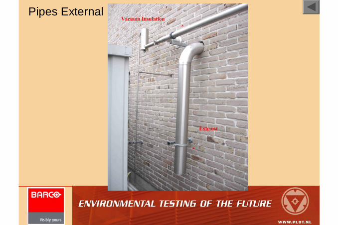
• Outside the lab• Pipes External ……………
• Thermal isolation by Vacuum
•Liquid Nitrogen Tank …........…• 5000 L (4500 L useful)
•Telemetry …………………………•Never empty
Ruimte voor uw eigen logo!
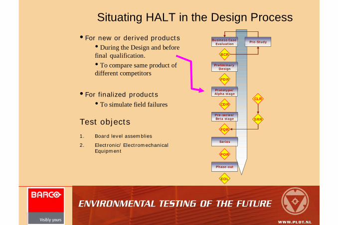
Situating HALT in the Design Process•For new or derived products
• During the Design and before final qualification.• To compare same product of different competitors
•For finalized products• To simulate field failures
Business Case Evaluation
PreliminaryDesign
Prototype/Alpha stage
Pre-series/Beta stage
Series
Phase-out
Pre-Study
BCR
PDR
CDR
FQR
POR
CLR
SRR
EOL
1. Board level assemblies
2. Electronic/ Electromechanical Equipment
Test objects

Ruimte voor uw eigen logo!
The HALT Procedure1. Define a HALT team with multiple disciplines (Project Leader,
Mech. resp, Elect. resp, Test executer)
Mech. Resp. and Elect. Resp: looking for root causes and implement corrective actions
2. Define the EUT and how to test (closed, open, cabling, …), fixation
3. Get the Operating Temperature and Vibration specifications (from Marketing/Sales or Customer) ………………………………………..
4. Define the Target Operational Limits for Temperature and Vibration ……………………………………………………………………………………..
5. Make an FMT (Functional Monitoring Test) and define the coverage (must cove at least the major functionality) ………….…
6. Check LN2-Volume left before extensive testing.
7. Fix the EUT in the chamber ……………………………………………………….Vibration Jig: stiff (transferring vibration energy at all frequencies)
low thermal inertion (cooling and heating rate)
open structure (air flow)
low weight (G level)
minimum number of resonances
8. Connect the accelerometers and the thermocouples ……………….
9. Run at least one FMT cycle before start of HALT
Before HALT

Ruimte voor uw eigen logo!
The HALT ProcedureDuring HALT
1. Continuously perform the FMT (it is not a humidity test !)
2. Monitor all HALT Parameters as a function of time (Temp, Vibr, FMT,…)
3. List the deviations, if any
What should be corrected / what not (LCD clearance,
Deformation of plastic housings, …) ?
• Perform root cause analysis• Implement a corrective action
• Cost of corrective action (time and material) ?
• Delay in product release ?
• Risk of non-implementation ?
• Benefit for other products ?
• Fundamental limit of technology ?
• Perform a verification HALT
Note: Do not “explain issues away” as this does not improve the reliability. It is a repeated “Stress – Fail – Fix” process.

Ruimte voor uw eigen logo!
The HALT Procedure1. Thermal Step Stress Test
LTOL
UTOL
Start at ambient Temperature
10 °C Decrements
Minimum dwell time = 12minutes
FMT 45 °C/min

Ruimte voor uw eigen logo!
The HALT Procedure2. Rapid Temperature Cycling
3. Vibration Step Testing (VOL)
Minimum 3 thermal cycles
UTOL – 5°C
LTOL + 5°C
Minimum dwell time = 10 minutes
Start at 5 gRMS
5 gRMS Increments
Minimum dwell time = 12minutes
FMT

Ruimte voor uw eigen logo!
The HALT Procedure4. Combined Testing
5 Temperature cycles
UTOL – 5°C
LTOL + 5°C
Target is 5 complete combined test cycles.
FMT
FMT
Vibration step = (VOL – 5 gRMS) / 5

Ruimte voor uw eigen logo!
The HALT Procedure5. Thermal Step Stress Test (if no Destructive Limits are encountered
during previous testing)
LTDL
UTDL

Ruimte voor uw eigen logo!
The HALT ProcedureAfter HALT
1. Make report (Report should be finished as Test is finished)
• Product identification
• Description of product fixture
• Location of response sensors
• Deviations from the standard HALT process
• FMT
• Detail of occurrences of unit degradation
• Root cause analysis + Corrective actions implemented
(Resulting in Engineering Changes)
• Summary of reached levels
2. Store all HALT data (so that the test sequence can be reproduced afterwards).
3. Clean up.
4. Keep test unit (if possible).

Ruimte voor uw eigen logo!
The HALT Procedure
• HALT in Barco is considered as being successful when:
• target limits are reached,• when failures occur, the failures are understood,• corrective actions are taken,• the product limits are clearly defined and pushed
as far as possible.

Ruimte voor uw eigen logo!
Practical Tips
• have knowledge of the equipment• LN2 Storage • LN2 Pressure stabilization (how it works)
• Max cooling performance versus max efficiency• Air pressure & Flow rate• fixation of EUT & pipes

Ruimte voor uw eigen logo!
Operating Cost• Renting of the LN2 tank • LN2 Consumption• Electricity / Compressed air• Operator (Almost Full Time)
LN2 Consumption
0
1000
2000
3000
4000
5000
6000
29/Dec/2004
17/Feb/2005
8/Apr/2005
28/May/2005
17/Jul/2005
5/Sep/2005
25/Oct/2005
14/Dec/2005
2/Feb/2006
24/Mar/2006
13/May/2006
time [-]
LN2
Con
sum
tion
/ day
Re
fill V
olum
e [L
]
0
500
1000
1500
2000
2500
3000
Refill Quanti ty LN2 Consum ption / day Linear (LN2 Consumption / day) Linear (Refill Quantity)

Ruimte voor uw eigen logo!
HALT Projects doneAVIONICS
1. Unit 1: Underfill Simulation of BGA failure in the field.
Broken connections underneath QUASAR chip
2. Unit 2:
3. Unit 3:
• 3 Ethernet failures have occurred during the test:• Abnormal flickering image on the display
• The unit reboots automatically when this failure occurs.• Combo card is resetting at random (this reset is typically triggered
by the main processor board)• Front of the EUT appears to reboot at random.
•The bottom plate of keyboard tablet has become loose during the Vibration Operation Limit (VOL) test
•Coil L6 (part of 3V3 switching regulator) has become loose from the plastic footprint with a broken inductor wire finally

Ruimte voor uw eigen logo!
HALT Projects doneDEFENCE
• Unit 1:
• Unit 2:
• Light leak on top of the unit that has become worse during the Short Term HALT.• Bad contact in the LCD connector (J5) on the PDB-Board of the Unit.• Electrolytic capacitor C388 on the VPB-Board of the VCM-1102 that has shortened.• Isolation of the VECTORLINK cable on the PM-side does become loose.
• one or more backlight lamps are not functioning anymore.• Bad contacts electrolytic capacitors

Ruimte voor uw eigen logo!
HALT Projects done
MEDICAL• Unit 1: Backlight (test of cracks in Light Guide)
• Unit 2: (with witnessing)
• A vertical tab is broken after about 3 minutes • light-leaks are visible at the bottom of the display • 5 electrolytic capacitors have broken off • Optical link does not function anymore• USB link does not function anymore

Ruimte voor uw eigen logo!
Other HALTs
• Rapid Voltage variation (determination of the Voltage margin)
• Power (On/Off) cycling (5000 cycles and perform FMT after each 500 cycles)
• …
Ruimte voor uw eigen logo!
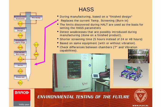
HASS•During manufacturing, based on a “finished design”• Replaces the current Temp. Screening (Burn-in)• The limits discovered during HALT are used as the basis for
setting the HASS parameters•Detect weaknesses that are possibly introduced during
manufacturing (done on a finished product).•Shorter screening time (5 hours instead of 24 or 48 hours)•Based on same equipment (with or without vibration).•Check differences between chambers (T° and Vibration
capabilities).
Business Case Evaluation
PreliminaryDesign
Prototype/Alpha stage
Pre-series/Beta stage
Series
Phase-out
Pre-Study
BCR
PDR
CDR
FQR
POR
CLR
SRR
EOL

Ruimte voor uw eigen logo!
HASS
UTOL+20°C
UTOL-10°C
Ambient temperature
LTOL+10°CLTOL
Time [min.]
Temperature[°C]
0.8 * VOL
0
Vibration [Grms]
Time [min.]
VOL
5
12 12 12 3015 305 5 1515
0 60 120 180
15 30 305 5 30
Power to EUT
On
OffTime [min.]
Power interruption of 2 min.
72
Start of Screening
End of Screening
+45°C/min.
-45°C/min.
72 115
Precipitation Phase
Detection Phase
Steepness depends on UTOL and
LTOL
UTOL
12 1212
72
Closed EUTOpen EUT

Ruimte voor uw eigen logo!
End

Ruimte voor uw eigen logo!
Telemetry

Ruimte voor uw eigen logo!
Pipes Inside
LN2Exhaust

Ruimte voor uw eigen logo!
Chamber itself
Model
Typhoon 3.0
Vibration
6 degree of freedom (3 translations and 3 rotations).
10 Hz – 5 kHz
50 GRMS min. (no load)
Thermal
-100 °C à +200 °C
Max. 70 °C/min.
Useful Volume
(91 x 91 x 89) cm³

Ruimte voor uw eigen logo!
Liquid Nitrogen Tank
Ruimte voor uw eigen logo!
Pipes External

Ruimte voor uw eigen logo!
Mechanical Fixation
VCM 1102
PM 1131
Front LCD
Back of the PM: electronics boards
are not covered
Pipe that blows underneath the panel module
2 pipes for the EUT
Both parts are not completely closed

Ruimte voor uw eigen logo!
EUT
To increase thermal transition rate

Ruimte voor uw eigen logo!
Defining the Target Operational Limits• No standard known, only guidelines, product dependent
For Barco Defined Products, the specification is the basis. • Target UTOL = Spec + 48°C• Target LTOL = Spec – 48°C• Target VOL = 20 GRMS + 12 GRMS à 35 GRMS

Ruimte voor uw eigen logo!
The Target Operational Limits• Low margins indicate poor performance (short life), • High margins indicate good performance (longer life).
Typical Medical Products, • Target UOL = +45 °C + 48 °C = + 95 °C• Target LOL = 0 °C – 48 °C = - 48 °C• Target VOL = 20 g + 12 g => 35 g
Typical Avionics Products,• Target UOL = +55 °C + 48 °C = + 103 °C• Target LOL = -25 °C – 48 °C = - 73 °C • Target VOL = 20 g + 12 g => 35 g
Typical Defence Products,• Target UOL = +63 °C + 48 °C = + 111 °C• Target LOL = -42 °C – 48 °C = - 90 °C• Target VOL = 20 g + 12 g => 35

Ruimte voor uw eigen logo!
Position of accelero’s
Measured level differs a lot from setpoint
Measured Level almost equal to setpoint