highways agency asset maintenance and operational...
TRANSCRIPT

Highways Agency
Asset Maintenance and
Operational Requirements
Area 10 Specifi c Requirements
Version 1.7July 2011

Page intentionally left blank.

Area 10 • AMOR Version 1.7
July 2011
Page 1
Asset Maintenance and Operational Requirements
Contents
Preface Document Control
Preface Defi ned Terms
Preface Abbreviations
Part 0 General
Part 1 Watchman Operational Requirement
Part 2 Managing Network Occupancy Operational Requirement
Part 3 Incident Response Operational Requirement
Part 4 Severe Weather Operational Requirement
Part 5 Drainage Maintenance Requirement
Part 6 Fences, Screens and Environmental Barriers Maintenance
Requirement
Part 7 Geotechnical Assets Maintenance Requirement
Part 8 Lighting Maintenance Requirement
Part 9 Paved Areas Maintenance Requirement
Part 10 Road Markings and Road Studs Maintenance Requirement
Part 11 Road Restraint Systems Maintenance Requirement
Part 12 Road Traffi c Signs Maintenance Requirement
Part 13 Soft Estate Maintenance Requirement
Part 14 Structures Maintenance Requirement
Part 15 Sweeping and Cleaning Maintenance Requirement
Part 16 Tunnels Maintenance Requirement

Page 2
Asset Maintenance and Operational Requirements
Area 10 • AMOR Version 1.7
July 2011
Appendices
Appendix 1 Intentionally Blank
Appendix 2 Managing Network Occupancy Operational Requirement
Appendix 3 Incident Response Operational Requirement
Appendix 4 Severe Weather Operational Requirement
Appendix 5 Intentionally Blank
Appendix 6 Intentionally Blank
Appendix 7 Intentionally Blank
Appendix 8 Intentionally Blank
Appendix 9 Intentionally Blank
Appendix 10 Intentionally Blank
Appendix 11 Road Restraint Systems Maintenance Requirement
Appendix 12 Intentionally Blank
Appendix 13 Intentionally Blank
Appendix 14 Intentionally Blank
Appendix 15 Sweeping and Cleaning Maintenance Requirement
Appendix 16 Intentionally Blank

Page 3
Asset Maintenance and Operational Requirements
Area 10 • AMOR Version 1.7
July 2011
Asset Maintenance and Operational Requirements
Document Control
AMOR Version:
Version
Number
Date
AMOR 1.7 July 2011
Defi ned Terms and Abbreviations Version:
Version
Number
Date
Defi ned Terms 1.4 June 2011
Abbreviations 1.2 May 2011
Requirement Version:
Version
Number
Date
Part 0 – General 1.3 June 2011
Part 1 – Watchman Operational Requirement 1.2 May 2011
Part 2 – Managing Network Occupancy Operational Requirement 1.3 June 2011
Part 3 – Incident Response Operational Requirement 1.4 June 2011
Part 4 – Severe Weather Operational Requirement 1.2 June 2011
Part 5 – Drainage Maintenance Requirement 1.2 June 2011
Part 6 – Fences, Screens and Environmental Barriers Maintenance Requirement
1.2 May 2011
Part 7 – Geotechnical Assets Maintenance Requirement 1.1 May 2011
Part 8 – Lighting Maintenance Requirement 1.3 June 2011
Part 9 – Paved Areas Maintenance Requirement 1.3 June 2011
Part 10 – Road Markings and Road Studs Maintenance Requirement
1.2 May 2011

Page 4
Asset Maintenance and Operational Requirements
Area 10 • AMOR Version 1.7
July 2011
Part 11 – Road Restraint Systems Maintenance Requirement 1.2 May 2011
Part 12 – Road Traffic Signs Maintenance Requirement 1.3 July 2011
Part 13 – Soft Estate Maintenance Requirement 1.1 May 2011
Part 14 – Structures Maintenance Requirement 1.3 July 2011
Part 15 – Sweeping and Cleaning Maintenance Requirement 1.1 April 2011
Part 16 – Tunnels Maintenance Requirement 1.1 May 2011
Appendix Version:
Version
Number
Date
Appendix 1 - Intentionally Blank
Appendix 2 - Managing Network Occupancy OperationalRequirement
1.1 June 2011
Appendix 3 - Incident Response Operational Requirement 1.1 April 2011
Appendix 4 - Severe Weather Operational Requirement 1.2 June 2011
Appendix 5 - Intentionally Blank
Appendix 6 - Intentionally Blank
Appendix 7 - Intentionally Blank
Appendix 8 - Intentionally Blank
Appendix 9 - Intentionally Blank
Appendix 10 - Intentionally Blank
Appendix 11 - Road Restraint Systems Maintenance Requirement 1.0 April 2011
Appendix 12 - Intentionally Blank
Appendix 13 - Intentionally Blank
Appendix 14 - Intentionally Blank
Appendix 15 - Sweeping and Cleaning Maintenance Requirement 1.0 April 2011
Appendix 16 - Intentionally Blank
Area 10 • AMOR Version 1.7
July 2011
Page 5
Asset Maintenance and Operational Requirements
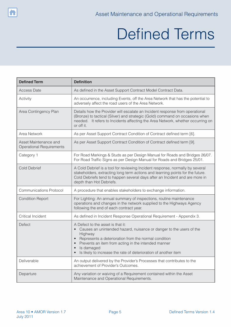
Defi ned Terms
Defi ned Term Defi nition
Access Date As defi ned in the Asset Support Contract Model Contract Data.
Activity An occurrence, including Events, off the Area Network that has the potential to
adversely affect the road users of the Area Network.
Area Contingency Plan Details how the Provider will escalate an Incident response from operational
(Bronze) to tactical (Silver) and strategic (Gold) command on occasions when
needed. It refers to Incidents affecting the Area Network, whether occurring on
or off it.
Area Network As per Asset Support Contract Condition of Contract defi ned term [6].
Asset Maintenance and
Operational Requirements
As per Asset Support Contract Condition of Contract defi ned term [9].
Category 1 For Road Markings & Studs as per Design Manual for Roads and Bridges 26/07.
For Road Traffi c Signs as per Design Manual for Roads and Bridges 25/01.
Cold Debrief A Cold Debrief is a tool for reviewing Incident response, normally by several
stakeholders, extracting long term actions and learning points for the future.
Cold Debriefs tend to happen several days after an Incident and are more in
depth than Hot Debriefs.
Communications Protocol A procedure that enables stakeholders to exchange information.
Condition Report For Lighting: An annual summary of inspections, routine maintenance
operations and changes in the network supplied to the Highways Agency
following the end of each contract year.
Critical Incident As defi ned in Incident Response Operational Requirement - Appendix 3.
Defect A Defect to the asset is that it:
• Causes an unintended hazard, nuisance or danger to the users of the
Highway
• Represents a deterioration from the normal condition
• Prevents an item from acting in the intended manner
• Is damaged
• Is likely to increase the rate of deterioration of another item
Deliverable An output delivered by the Provider’s Processes that contributes to the
achievement of Provider’s Outcomes.
Departure Any variation or waiving of a Requirement contained within the Asset
Maintenance and Operational Requirements.
Defi ned Terms Version 1.4

Page 6
Asset Maintenance and Operational Requirements
Area 10 • AMOR Version 1.7
July 2011
Defi ned Term Defi nition
Designated Sites Nationally-designated sites comprise: Sites of Special Scientifi c Interest; Local
sites, Nature Reserves; Areas of Outstanding Natural Beauty.
Internationally-designated sites cover those with European designations
including Special Areas of Conservation and Special Protection Areas;
and those with international designations, such as Ramsar sites of wetland
importance.
Detailed Local Operating
Agreement
A working document that describes the procedures, protocols and
communication methods to be used by each Local Highway Authority and
the National Traffi c Control Centre in exchanging and acting upon operational
information.
Distribution Network
Operator
The operator of the power supply to lighting within the Area Network.
Drainage Liaison Engineer A nominated person from the Provider organisation, approved by the Service
Manager, who is responsible for all drainage surveys, maintenance and
renewals, and is the key point of contact within their organisation for all
drainage related matters.
Emergency Diversion Route An off Area Network diversion route used when an Area Network closure occurs
and traffi c from the Strategic Road Network is diverted along agreed Local
Highway Authority routes.
Emergency Services As per Asset Support Contract Condition of Contract defi ned term [36].
Emergency Traffi c
Management
As defi ned in Traffi c Signs Manual Chapter 8 – Part 2.
Employer As per Asset Support Contract Model Contract Data.
Employer’s Vehicles As per ASC Condition of Contract defi ned term [39].
Environment Agency Flood
Warning System
Provides warnings of river and coastal fl ooding.
Environmental Management
Plan
An Environmental Management Plan is a document (or set of documents),
which set out agreed procedures and standards for the implementation of
identifi ed environmental management actions. It is developed to address
the adverse and benefi cial environmental impacts arising from planning and
design, construction and maintenance and operation of the Area Network.
Equipment As per Asset Support Contract Condition of Contract defi ned term [41].
Event A planned off Area Network event that has the potential to have an adverse
effect on road users of the Strategic Road Network.
Events Calendar A calendar containing specifi ed details of all planned Events.
Flood Champion The member of the Provider organisation responsible for integration and
coordination of fl ood risk management within their organisation.
Flood Event The accumulation or passage of water at the ground surface where it is not
normally experienced.
Flood Hotspot A location at high risk of repeated fl ooding.
Forward Programme As per Asset Support Contract Condition of Contract defi ned term [45].
Defi ned Terms Version 1.4

Page 7
Asset Maintenance and Operational Requirements
Area 10 • AMOR Version 1.7
July 2011
Defi ned Term Defi nition
General Inspection As defi ned by the Design Manual for Roads and Bridges for the relevant asset.
Geotechnical Asset
Management Plan
As defi ned in HD 41.
Heavily Traffi cked As defi ned in Asset Support Contract Service Information Annex 13:
Additional Performance Requirements to Asset Maintenance and Operational
Requirements.
Highway As per Asset Support Contract Condition of Contract defi ned term [6] - Area
Network.
Hot Debrief A Hot Debrief is a tool for reviewing Incident response, extracting immediate
actions to take and learning points for the future. Hot Debriefs must take
place immediately after appropriate Incidents and outcomes should be
communicated to the Service Manager.
Incident As per Asset Support Contract Condition of Contract defi ned term [49].
Incident Data Capture Sheet A form detailing the information (fi elds and format) that Providers are required to
record for each Incident attended.
Incident Response Plan An overarching strategic plan setting out the resources, Processes, Procedures
and Suppliers used by the Provider to deliver Incident response (as required by
Annex 24).
Information Systems As per Asset Support Contract Condition of Contract defi ned term [52].
Lane Closure The time when it is confi rmed that there is an Incident impacting a live lane on
the carriageway and this is notifi ed to the Network Control Centre.
Lane Opening The time when the RCC records that the lane closure is no longer impacted by
the Incident and this is notifi ed to the Network Control Centre.
Lighting Asset Management
and Maintenance Manual
The manual which sets out the policies and guidance for the whole lifecycle
relating to road lighting systems on the Strategic Road Network.
Lighting Asset Management
Plan
The Provider’s document describing what maintenance activities are planned
(and when) for the lighting asset for the next 12 months.
Lighting Operational
Performance Surveys
Scouting to assess and record lighting condition.
Lightly Traffi cked As defi ned in Asset Support Contract Service Information Annex 13:
Additional Performance Requirements to Asset Maintenance and Operational
Requirements.
Local Highway Authority An authority responsible for local roads under relevant legislation.
Maintenance Requirement A Requirement relating to maintenance service delivery.
Maintenance Requirements
Plan
An overarching strategic plan that sets out the Provider’s approach to
inspections, assessment, Defect repair resources, Processes and Procedures.
Major Incident As defi ned in Incident Response Operational Requirement - Appendix 3.
Mobilisation Period As per Asset Support Contract Condition of Contract defi ned term [61].
National Reserve Fleet As per Asset Support Contract Condition of Contract defi ned term [63].
Defi ned Terms Version 1.4

Page 8
Asset Maintenance and Operational Requirements
Area 10 • AMOR Version 1.7
July 2011
Defi ned Term Defi nition
National Traffi c Control
Centre
As per Asset Support Contract Service Information defi ned terms [2].
Network Information Network Information is information which is in the document of that name
referred to in the Contract Data Part One and which describes the Area
Network, the Regional Technology Network and the Traffi c Technology Systems
and their surroundings and provides information pertaining to them and the
Employer’s assets.
Network Occupancy Plan A plan developed by the Provider that describes the approach and controls
under which network occupancy will be managed.
Nonconformity As per Asset Support Contract Condition of Contract defi ned term [68].
Occupancy All works, all Abnormal Indivisible Load movements, all Incidents or all events
that take place on the Area Network.
Operation and Maintenance
Manual
For tunnels: the manual, specifi c to each tunnel, which sets out operation,
maintenance and emergency response procedures.
Operational Requirement A Requirement relating to operational service delivery.
Operational Summer Period The period commencing 1st May and ending 30th September (inclusive).
Operational Winter Period As per Asset Support Contract Condition of Contract defi ned term [71].
Others As per Asset Support Contract Condition of Contract defi ned term [73].
Performance Metric A metric that describes the output performance relating to a Provider Outcome,
Deliverable, Process or Procedure.
Performance Requirement
Level
The level of performance the Provider needs to achieve related to a specifi c
Performance Metric.
Principal Inspection Has the meaning given in the Design Manual for Roads and Bridges.
Priority Drainage Asset Those assets which, if poorly managed or inadequate, pose a risk to either the
safety or journey time reliability of road users, or to adjacent property, or to the
water environment (or any combination of these).
Procedure As per Asset Support Contract Condition of Contract defi ned term [86].
Process As per Asset Support Contract Condition of Contract defi ned term [87].
Provider As per Asset Support Contract Condition of Contract defi ned term [50] and
Asset Support Contract Model Contract Data.
Provider Outcome An outcome required to be achieved by the Provider in relation to a specifi c
Maintenance or Operational Requirement within the Asset Maintenance and
Operational Requirements.
Quality Plan As per Asset Support Contract Condition of Contract defi ned term [97].
Regional Control Centre The Regional Control Centre provides a regional focus for the management and
operation of the Strategic Road Network.
Defi ned Terms Version 1.4

Page 9
Asset Maintenance and Operational Requirements
Area 10 • AMOR Version 1.7
July 2011
Defi ned Term Defi nition
Rolling A method of measuring distance between Defects in which the distance
measure begins at 0 when a Defect is encountered and ends when the next
Defect is encountered. For the purpose of this defi nition, Defects are of the
same type within the same stated lateral footprint (i.e. within a lane, within a
carriageway) and measured in the direction of traffi c fl ow.
Salt Restocking Plan This plan describes levels of stock required by the Providers and the future
procurement arrangements for this resource.
Schedule of Road Works Schedule of Road Works, as part of the Highways Agency Pavement
Management System suite, is a fully integrated application for the recording
and updating of lane closures on the Strategic Road Network consisting of
a database, form based and mapping based user interfaces and reporting
facilities.
Scheme As per Asset Support Contract Condition of Contract defi ned term [105].
Scope The extent of the work encompassed by a Maintenance or Operational
Requirement.
Service Information Contractual document defi ning the Services that the Provider shall undertake.
Service Manager As per Asset Support Contract Model Contract Data.
Services As per Asset Support Contract Condition of Contract defi ned term [109].
Severe Weather Plan The plan describes the different activities undertaken by the Provider as part
of the severe weather service including details of procedures, operational
arrangements, resources and contact information.
Special Inspection As defi ned by the Design Manual for Roads and Bridges for the relevant asset.
Statutory Undertaker Means an undertaker for the purpose of Part III of the New Roads and Street
Works Act 1991 as defi ned in Section 48(4) of that Act and exercising a relevant
statutory function as defi ned in Section 105(1) of that Act.
Strategic Road Network The network of Motorways and All Purpose Trunk Roads that are the
responsibility of the Highways Agency.
Structures Maintenance
Manual
As per Maintenance Manual given in Part 1 of Volume 3 of the Design Manual
for Roads and Bridges.
Supplier As per Asset Support Contract Condition of Contract defi ned term [114].
Tactical Incident Response
Plan
The Tactical Incident Response Plan details the level of Provider response,
planned actions to make safe and estimated time to clearance.
The Tactical Incident Response Plan is recorded on the Provider’s command
and control system.
Temporary Traffi c
Management
As defi ned in Traffi c Signs Manual Chapter 8 – Part 2.
Traffi c Offi cers As per Asset Support Contract Condition of Contract defi ned term [119].
Traffi c Technology Systems As per Asset Support Contract Condition of Contract defi ned term [120].
Defi ned Terms Version 1.4
Page 10
Asset Maintenance and Operational Requirements
Area 10 • AMOR Version 1.7
July 2011
Defi ned Term Defi nition
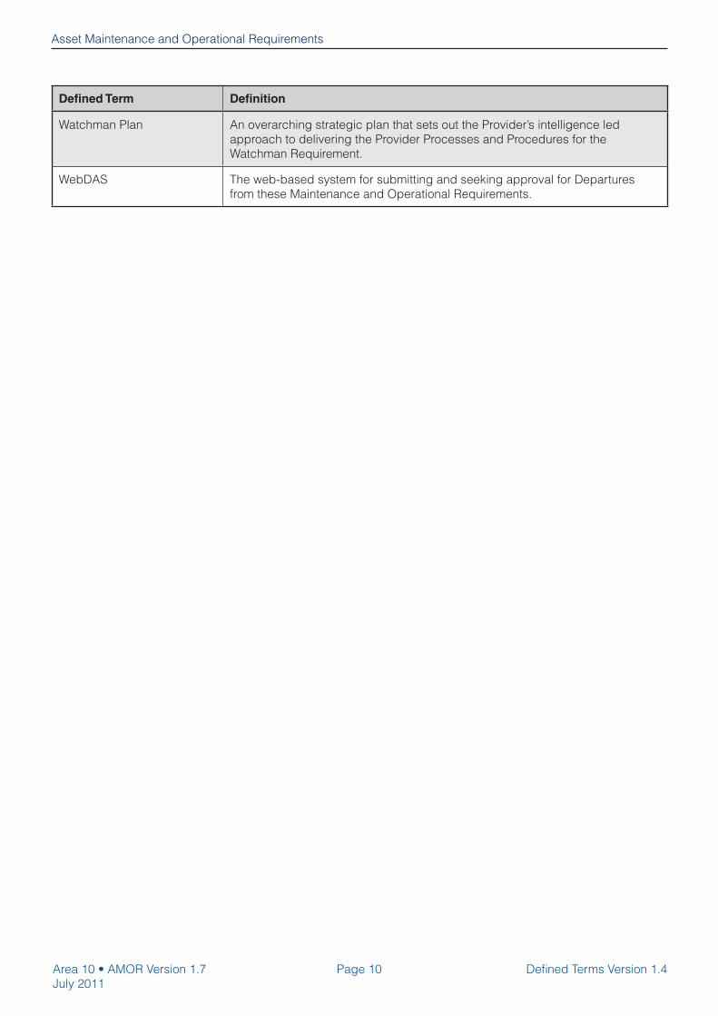
Watchman Plan An overarching strategic plan that sets out the Provider’s intelligence led
approach to delivering the Provider Processes and Procedures for the
Watchman Requirement.
WebDAS The web-based system for submitting and seeking approval for Departures
from these Maintenance and Operational Requirements.
Defi ned Terms Version 1.4

Page 11
Asset Maintenance and Operational Requirements
Area 10 • AMOR Version 1.7
July 2011
Abbreviation
ACPO Association of Chief Police Offi cers
ADMM Asset Data Management Manual
AIL Abnormal Indivisible Loads
AIRSweb Accident Incident Reporting System
AMOR Asset Maintenance and Operational Requirements
APTR All Purpose Trunk Roads
ASC Asset Support Contract
AW Authorised Weight
BIS Business, Innovation and Skills
CCTV Closed Circuit Television
CBRN Chemical, Biological, Radiological or Nuclear
COI Central Offi ce of Information
C&U Construction and Use
DLE Drainage Liaison Engineer
DMRB Design Manual for Roads and Bridges
DNO Distribution Network Operator
EDR Emergency Diversion Route
ENOM Enhanced Network Occupancy Management
EMP Environmental Management Plan
EPO Emergency Planning Offi cer
ESDAL Electronic Service Delivery for Abnormal Loads
ETM Emergency Traffi c Management
GAMP Geotechnical Asset Management Plan
HA Highways Agency
HADDMS Highways Agency Drainage Data Management System
HAPEP Highways Agency Planned Events Process
HAPMS Highways Agency Pavement Management System
HAZMAT Hazardous Material
JTR Journey Time Reliability
Asset Maintenance and Operational Requirements
Abbreviations
Abbreviations Version 1.2

Page 12
Asset Maintenance and Operational Requirements
Area 10 • AMOR Version 1.7
July 2011
Abbreviation
LAMMM Lighting Asset Management and Maintenance Manual
LAMP Lighting Asset Management Plan
LCPO Lowest Cost Practicable Option
LHA Local Highway Authority
MCHW Manual of Contract Documents for Highways Works
MNO Managing Network Occupancy
MRP Maintenance Requirement Plan
NCC Network Control Centre
NGF National Guidance Framework for Operational Activities
NVA Non-Value Added
NRSWA New Roads and Street Works Act 1991
NRTS National Roads Telecommunications Service
NTCC National Traffi c Control Centre
O&MM Operation and Maintenance Manual
PI Principal Inspection
PR Public Relations
QMS Quality Management System
RCC Regional Control Centre
RDD Regional Divisional Director
RIU Regional Intelligence Unit
RRS Road Restraint System
RTMC Regional Technology Maintenance Contract
SCADA Supervisory Control And Data Acquisition
SDT Service Delivery Team
SO Special Order
SRN Strategic Road Network
SRW Schedule of Road Works
STGO Special Type General Order
SWP Severe Weather Plan
TAA Technical Approval Authority
TCB Tension Corrugated Beam
TIRP Tactical Incident Response Plan
TMMM Technology Management and Maintenance Manual
TOS Traffi c Offi cer Service
TSM Traffi c Signs Manual
TSRGD Traffi c Signs Regulations and General Directions
Abbreviations Version 1.2

Page 13
Asset Maintenance and Operational Requirements
Area 10 • AMOR Version 1.7
July 2011
Abbreviation
TTM Temporary Traffi c Management
VA Value Added
VMS Variable Message Signage
WebDAS Web based Departures Approval Systems
WEEE Waste Electrical and Electronic Equipment
WRF1 Winter Reporting Form
Abbreviations Version 1.2

Page intentionally left blank.

Asset Maintenance and Operational Requirements
Part 0 – Page 1Area 10 • AMOR Version 1.7
July 2011
Part 0 Version 1.3
Part 0
GeneralVersion 1.3
Area 10 • AMOR Version 1.7
July 2011
Part 0 Version 1.3
Asset Maintenance and Operational Requirements – Part 0 – General
Part 0 – Page 2
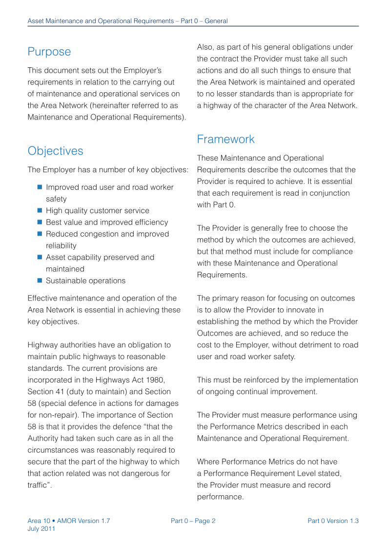
Purpose
This document sets out the Employer’s
requirements in relation to the carrying out
of maintenance and operational services on
the Area Network (hereinafter referred to as
Maintenance and Operational Requirements).
Objectives
The Employer has a number of key objectives:
Improved road user and road worker
safety
High quality customer service
Best value and improved effi ciency
Reduced congestion and improved
reliability
Asset capability preserved and
maintained
Sustainable operations
Effective maintenance and operation of the
Area Network is essential in achieving these
key objectives.
Highway authorities have an obligation to
maintain public highways to reasonable
standards. The current provisions are
incorporated in the Highways Act 1980,
Section 41 (duty to maintain) and Section
58 (special defence in actions for damages
for non-repair). The importance of Section
58 is that it provides the defence “that the
Authority had taken such care as in all the
circumstances was reasonably required to
secure that the part of the highway to which
that action related was not dangerous for
traffi c”.
Also, as part of his general obligations under
the contract the Provider must take all such
actions and do all such things to ensure that
the Area Network is maintained and operated
to no lesser standards than is appropriate for
a highway of the character of the Area Network.
Framework
These Maintenance and Operational
Requirements describe the outcomes that the
Provider is required to achieve. It is essential
that each requirement is read in conjunction
with Part 0.
The Provider is generally free to choose the
method by which the outcomes are achieved,
but that method must include for compliance
with these Maintenance and Operational
Requirements.
The primary reason for focusing on outcomes
is to allow the Provider to innovate in
establishing the method by which the Provider
Outcomes are achieved, and so reduce the
cost to the Employer, without detriment to road
user and road worker safety.
This must be reinforced by the implementation
of ongoing continual improvement.
The Provider must measure performance using
the Performance Metrics described in each
Maintenance and Operational Requirement.
Where Performance Metrics do not have
a Performance Requirement Level stated,
the Provider must measure and record
performance.

Part 0 – Page 3Area 10 • AMOR Version 1.7
July 2011
Part 0 Version 1.3
Asset Maintenance and Operational Requirements – Part 0 – General
Outcome Based Structure
All the individual Maintenance and Operational Requirements are structured as Figure 0.1:
Figure 0.1 Outcome Based Structure
Provider OutcomesProvider Outcomes
Deliverables
Processes
Procedures
Specific Deliverables that the Employer requires the Provider to
deliver in contributing to the achievement of the Provider Outcome.
These must be included in the Provider’s Quality Plan. They are in
addition to any other Deliverables that the Provider considers
necessary to achieve the Provider Outcome.
Specific Processes that the Employer requires the Provider to
include in his Quality Plan to produce the Deliverables. They are in
addition to the Processes that the Provider requires to implement
these Maintenance and Operational Requirements.
Specific Procedures that the Employer requires the Provider to
include as part of his Processes in his Quality Plan. They are in
addition to any other Procedures that the Provider requires as part
of his Processes.
Outcome required to be achieved by the Provider.
Scope of work covered by Maintenance or Operational
Requirement.
Scope
The Deliverables, Processes and Procedures
are not exhaustive. They represent what the
Employer specifi cally requires the Provider to
carry out as a minimum. The Provider must
in addition establish his own Deliverables,
Processes and Procedures necessary to fulfi l
his obligations under these Maintenance and
Operational Requirements, and deliver the
Provider Outcomes.
Meeting any Performance Requirement
Level identifi ed in these Maintenance and
Operational Requirements is not determinative
of compliance with the Provider Outcomes.

Area 10 • AMOR Version 1.7
July 2011
Part 0 Version 1.3
Asset Maintenance and Operational Requirements – Part 0 – General
Part 0 – Page 4
Any failure to deliver a Provider Outcome,
Deliverable, Process or Procedure is deemed
to be a Nonconformity, and will require root
cause analysis and corrective action in
accordance with Annex 19 of the Service
Information (Reports).
Notwithstanding the preceding paragraph,
a failure to deliver a Provider Outcome will
not be a Nonconformity if, and only if, the
Provider has carried out and complied with
the relevant Procedures, Processes and
Deliverables (both those included in these
Maintenance and Operational Requirements
and any additional ones that the Provider
deems necessary) and the root cause of
the failure is due to circumstances that are
wholly outside the control of the Provider and
could not reasonably have been foreseen
by a provider experienced in highways
maintenance and operations.
Within each Maintenance and Operational
Requirement there is a schedule of
Performance Metrics and the Provider must
measure his performance using these metrics
all in accordance with Annex 15 of the Service
Information (Performance Management).
Risk Based Methodology
The Provider must take a risk based
approach to the execution of maintenance
and operations in order to provide the best
value for money for the Employer whilst
demonstrating that risks are being mitigated
to an acceptable level with no detriment to
road user and road worker safety.
In the context of these Maintenance and
Operational Requirements a risk based
approach means that the Provider prioritises
and targets his activities as he deems
necessary, using data and information about
the Area Network in order to make intelligence
led decisions about where and when to
undertake maintenance activities.
The primary risks that the Provider must
mitigate are:
Risks to safety – these must be
mitigated to ensure that the Area
Network is not dangerous to traffi c and
does not present a risk to road user
or road worker safety and provides
the Employer with a ‘special defence’
under Section 58 of the Highways Act
1980.
Risks to availability – these must be
mitigated to ensure the Provider, so
far as may be reasonably practicable
having regard to the Employer’s other
obligations, policies and objectives,
secures the expeditious movement
of traffi c on the Area Network and
facilitates the expeditious movement
of traffi c on road networks for which
another authority is the traffi c authority.
This involves the Provider establishing a
thorough understanding of the character of
the Area Network and the traffi c expected to
use it.
Based on this understanding, and knowledge
of the Area Network condition including risks,

Part 0 – Page 5Area 10 • AMOR Version 1.7
July 2011
Part 0 Version 1.3
Asset Maintenance and Operational Requirements – Part 0 – General
Defects and potential Defects, the Provider
must prioritise his activities as he deems
necessary in order to optimise the use of,
and achieve best value from the available
resources. The Provider develops clear
Processes and Procedures to effectively
undertake this prioritisation as part of his
Quality Plan.
The safe and effective identifi cation and
control of Defects is a key aspect of these
Maintenance and Operational Requirements.
A Defect to the asset is that it:
Causes an unintended hazard, nuisance
or danger to the users of the highway
Represents a deterioration from the
normal condition
Prevents an item from acting in the
intended manner
Is damaged
Is likely to increase the rate of
deterioration of another item
The output from these Maintenance and
Operational Requirements becomes an
input to the Processes for the identifi cation
and development of renewal Schemes, as
illustrated in Figure 0.2 below.
Reference should be made to Annex 20 of the
Service Information (Scheme Development) in
relation to Scheme identifi cation.
The Provider must ensure that the interface
with his Scheme identifi cation process
is effectively managed and coordinated
by ensuring that these Maintenance and
Operational Requirements are fulfi lled by the
Provider prior to proposing Schemes.
ASC - Lump Sum Duties Employer’s Forward Programme
1. Inspect Asset
2. Inventory and Condition Data Capture
3. Preventative Maintenance
or
Make Safe
or
Temporary Repair
or
VFM Permanent Repair
1. Inspect Asset
2. Inventory and Condition Data Capture
3. Preventative Maintenance
or
Make Safe
or
Temporary Repair
or
VFM Permanent Repair
Proposed
Schemes
Employer
in Control
Employer
decides ‘when’
Employer
decides ‘what’
Figure 0.2 Overview of relationship between Maintenance and
Operational Requirements and Scheme identification
Annex 20

Area 10 • AMOR Version 1.7
July 2011
Part 0 Version 1.3
Asset Maintenance and Operational Requirements – Part 0 – General
Part 0 – Page 6
Schemes identifi ed by the Provider
must be based on the prioritised needs
of the Area Network as described in
the Employer’s Network Delivery and
Development Programme Development
Management Manual and Value Management
Requirements.
The Provider records his performance in
accordance with the requirements of Annex
15 of the Service Information (Performance
Management) and uses measurement data to
continually improve his performance reducing
cycle times and cost.
Key Operational Processes
for the Provider
The Provider carries out his activities in a
manner that provides the Employer with a
“special defence” under Section 58 of the
Highways Act 1980.
The Provider adopts the key Processes shown
in Figures 0.3 and 0.4 (with associated activity
notes) in relation to risk based inspections
and the risk based making safe and repair of
the asset.
These are minimum requirements and the
Provider must supplement them with any
activity he deems necessary to meet his
contractual obligations and to deliver the
Provider Outcomes.
The Provider must include fully detailed
Processes, Procedures and timescales in his
Quality Plan in relation to inspection, make
safe and repair of the asset.

Part 0 – Page 7Area 10 • AMOR Version 1.7
July 2011
Part 0 Version 1.3
Asset Maintenance and Operational Requirements – Part 0 – General
Figure 0.3 Risk Based Inspection Process
Increase inspection frequency as required
(see Figure 0.4)
MSRP8
Establish all sources of information about
condition data
Establish all sources of information about
condition data
IP1
Establish risk characteristics for each
Maintenance Requirement
Establish risk characteristics for each
Maintenance Requirement
IP2
Develop programme of inspections based on risk
characteristics
Develop programme of inspections based on risk
characteristics
IP3
Undertake inspectionsUndertake inspections
IP4
Update records and Employer’s systemsUpdate records and Employer’s systems
IP5
Identify Defects that require monitoring,
reschedule inspection as necessary and inspect
Identify Defects that require monitoring,
reschedule inspection as necessary and inspect
IP6
Ensure warning notices of the condition of the
Defects are placed as necessary
Ensure warning notices of the condition of the
Defects are placed as necessary
IP7
Take photographic evidence
Take photographic evidence
IP8
Opportunity to undertake preventative maintenance
(see Figure 0.4)
MSRP5

Area 10 • AMOR Version 1.7
July 2011
Part 0 Version 1.3
Asset Maintenance and Operational Requirements – Part 0 – General
Part 0 – Page 8
Risk Based Inspection Process – Activity Notes
IP1 Establish all sources of
information about condition
data
During the Mobilisation Period the Provider must review existing
records and establish all sources of information where knowledge
can be gained about asset condition. The Provider must take all
reasonable care to identify parts of the Area Network that are likely to
cause danger to users of the highway.
IP2 Establish risk characteristics
for each Maintenance
Requirement
There will be different risk characteristics for each Maintenance and
Operational Requirement i.e. the different types of risk that could
affect achievement of the Provider Outcomes or cause a danger
to users of the highway. The Provider must establish these risk
characteristics in the context of the variable nature and character
of the Area Network i.e. a normally low risk may become a high risk
depending on its context in the Area Network – the Provider must
understand these conditions.
IP3 Develop programme of
inspections based on risk
characteristics
The Provider develops a programme of inspections for each
Maintenance Requirement recognising the risk characteristics. The
programme must be coordinated in order to avoid unnecessary lane
closures.
IP4 Undertake inspections In addition to any Procedures mandated by the Employer, the
Provider must have Procedures in place for undertaking inspections.
The Provider must have mechanisms in place for checking and
controlling the quality of inspections. The Provider takes the
opportunity to undertake preventative maintenance or make safe
Defects following inspections.
IP5 Update records and
Employer’s systems
The Provider updates his own systems as necessary and also the
Employer systems in accordance with the requirements of Annex 25
of the Service Information (Integrated Asset Management).
IP6 Identify Defects that require
monitoring, reschedule
inspections as necessary
and inspect
The Provider monitors Defects that have the potential for deterioration
and could cause a risk to the achievement of the Provider’s Outcome
or cause a danger to the users of the highway. The Provider adjusts
his inspection regime accordingly.
IP7 Ensure warning notices of
the condition of the Defects
are placed as necessary
The Provider displays warning notices of the condition of the highway
in relation to Defects that could cause danger to the users of the
highway.
IP8 Take photographic evidence The Provider must take photographic evidence during inspections
to be made available as evidence of compliance with these
Maintenance and Operational Requirements.

Part 0 – Page 9Area 10 • AMOR Version 1.7
July 2011
Part 0 Version 1.3
Asset Maintenance and Operational Requirements – Part 0 – General
Figure 0.4 Risk Based Make Safe and Repair Process
Carry out preventative maintenance
Carry out preventative maintenance Make safeMake safe
Update records and Employer’s systemsUpdate records and Employer’s systems
Measure and improvecycle times
Measure and improvecycle times
Increase inspection frequency as required -
see Figure 0.3, IP2
Increase inspection frequency as required -
see Figure 0.3, IP2
Defect prioritisationDefect prioritisation
Record awarenessof Defects
Record awarenessof Defects
Categorise DefectsCategorise Defects
Carry outtemporary repair
Carry outtemporary repair
Carry out permanent repair as deemed appropriate by the
Provider
Carry out permanent repair as deemed appropriate by the
Provider
MSRP1
MSRP2
MSRP3
MSRP8
MSRP5 MSRP4
MSRP9
MSRP10
MSRP6 MSRP7
Area 10 • AMOR Version 1.7
July 2011
Part 0 Version 1.3
Asset Maintenance and Operational Requirements – Part 0 – General
Part 0 – Page 10
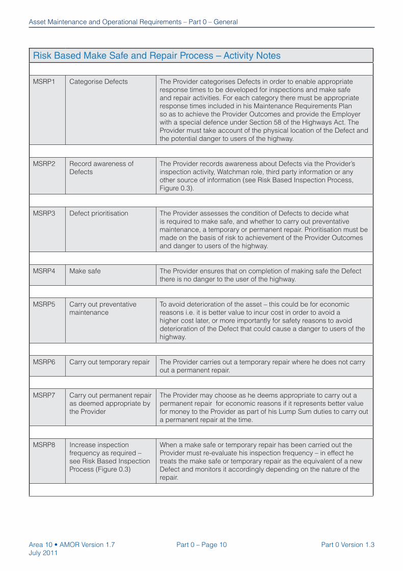
Risk Based Make Safe and Repair Process – Activity Notes
MSRP1 Categorise Defects The Provider categorises Defects in order to enable appropriate
response times to be developed for inspections and make safe
and repair activities. For each category there must be appropriate
response times included in his Maintenance Requirements Plan
so as to achieve the Provider Outcomes and provide the Employer
with a special defence under Section 58 of the Highways Act. The
Provider must take account of the physical location of the Defect and
the potential danger to users of the highway.
MSRP2 Record awareness of
Defects
The Provider records awareness about Defects via the Provider’s
inspection activity, Watchman role, third party information or any
other source of information (see Risk Based Inspection Process,
Figure 0.3).
MSRP3 Defect prioritisation The Provider assesses the condition of Defects to decide what
is required to make safe, and whether to carry out preventative
maintenance, a temporary or permanent repair. Prioritisation must be
made on the basis of risk to achievement of the Provider Outcomes
and danger to users of the highway.
MSRP4 Make safe The Provider ensures that on completion of making safe the Defect
there is no danger to the user of the highway.
MSRP5 Carry out preventative
maintenance
To avoid deterioration of the asset – this could be for economic
reasons i.e. it is better value to incur cost in order to avoid a
higher cost later, or more importantly for safety reasons to avoid
deterioration of the Defect that could cause a danger to users of the
highway.
MSRP6 Carry out temporary repair The Provider carries out a temporary repair where he does not carry
out a permanent repair.
MSRP7 Carry out permanent repair
as deemed appropriate by
the Provider
The Provider may choose as he deems appropriate to carry out a
permanent repair for economic reasons if it represents better value
for money to the Provider as part of his Lump Sum duties to carry out
a permanent repair at the time.
MSRP8 Increase inspection
frequency as required –
see Risk Based Inspection
Process (Figure 0.3)
When a make safe or temporary repair has been carried out the
Provider must re-evaluate his inspection frequency – in effect he
treats the make safe or temporary repair as the equivalent of a new
Defect and monitors it accordingly depending on the nature of the
repair.

Part 0 – Page 11Area 10 • AMOR Version 1.7
July 2011
Part 0 Version 1.3
Asset Maintenance and Operational Requirements – Part 0 – General
MSRP9 Update records and
Employer’s systems
The Provider updates his own systems as necessary and also the
Employer systems in accordance with the requirements of Annex
25 of the Service Information (Integrated Asset Management). The
Provider must have a system for recording photographic evidence
showing the condition of the Defect before and after the repair or
make safe activity.
MSRP10 Measure and improve
cycle times
The Provider must record details of his performance in relation to
responding to Defect notifi cations and making safe or temporary/
permanent repair. From the outset the Provider must utilise the
methodology in Annex 14 of the Service Information (Continual
Improvement) and employ Lean techniques to optimise the value
adding activities, minimise the non-value adding activities and
eliminate waste in his Processes and Procedures.
Provider Obligations
The Provider must deliver these Maintenance
and Operational Requirements in accordance
with all of his obligations under the contract,
including but not limited to the following:
1. The Quality Plan must include those
Deliverables, Processes and Procedures
stated here as being specifi cally required
by the Employer.
2. The key operational processes described
above must be adopted by the Provider
and included in his Quality Plan
3. The Quality Plan must include for the
provision of a Maintenance Requirements
Plan (see below for coverage) covering
the various Maintenance Requirements,
and there must be separate plans for
the operational areas covering Severe
Weather Service, Incident Response
and Managing Network Occupancy as
required by Annex 24 of the Service
Information (Quality Plan Framework).
The plans must detail exactly what
activities the Provider is going to
undertake to deliver the Provider
Outcomes and avoid danger to users
of the highway including timescales
resource levels, frequency of operations,
and work outputs. They must include any
activities undertaken by the Provider’s
suppliers. The various plans must be kept
updated as required.
4. In developing his Quality Plan in respect
of these Maintenance and Operational
Requirements the Provider must adopt
the Quality Policy themes covered by
Annex 24 of the Service Information
(Quality Plan Framework) e.g. where
cycle time is an important part of
delivering the outcome the Provider must
take account of the ‘Fast’ theme when
designing his Processes and Procedures.
5. The Provider carries out these
Maintenance and Operational
Requirements in compliance with all laws,
statutes, regulations, by-laws, directives,
rules and government orders applicable

Area 10 • AMOR Version 1.7
July 2011
Part 0 Version 1.3
Asset Maintenance and Operational Requirements – Part 0 – General
Part 0 – Page 12
to the Employer, Provider or the Services
to the extent that they are applicable to
any part of the Services.
6. The Provider carries out these
Maintenance and Operational
Requirements in accordance with all
Health and Safety requirements stated in
the Service Information.
7. Where any document, Process or
Procedure is stated in these Maintenance
and Operational Requirements, these are
deemed to be the latest versions.
8. All hold points are observed and the
Provider has documented release
mechanisms in place, as defi ned within
the Maintenance Requirements.
9. Where the Provider’s activities need
to be co-ordinated with Others (e.g.
Employer’s contractors) or different parts
of the Employer’s organisation (e.g. Traffi c
Offi cers) the Provider ensures that the
activity interfaces are effectively and
effi ciently managed.

Part 0 – Page 13Area 10 • AMOR Version 1.7
July 2011
Part 0 Version 1.3
Asset Maintenance and Operational Requirements – Part 0 – General
VA ActivityVA Activity NVA Activity Waste
Provider becomes aware
of Defect
Provider makes safe Defect
Optimise the Value Adding (VA) activities e.g. ensure Procedure in place to deliver
effective inspections and to collect information from other sources e.g.
Watchman Role, public and 3rd party notifications.
Minimise the NVA activities e.g. ensure any necessary travel time to Defect site is minimised.
Eliminate waste e.g. ensure no unnecessary waiting time between becoming aware of Defect and mobilising correct
resource to attend.
These functions are carried out during the initial Quality Plan process design and continually thereafter in order to reduce cycle times, improve the effectiveness of all activities, and achieve the desired outcome.
Utilisation of Lean process design and continual improvement principles for
Maintenance and Operational Requirements
Make safe Defect example
Reducing cycle times by minimising Non Value Adding (NVA) and eliminating waste
improves safety as well as reducing cost.
Figure 0.5 Continual Improvement Principles
The presence of NVA and Waste extends the time taken to make safe
10. The Provider uses Processes and
Procedures that are cost and time
effi cient, ensuring that value adding
activities are optimised, non-value
adding activity is minimised, and waste
is eliminated. Continual improvement
opportunities must be sought utilising
the mechanisms covered by Annex 14
of the Service Information (Continual
Improvement) to reduce cycle times,
and generate effi ciency savings and
innovations required by Clause 53 and 54
respectively of the Conditions of Contract.
Figure 0.5 gives an example of the
application of these principles.

Area 10 • AMOR Version 1.7
July 2011
Part 0 Version 1.3
Asset Maintenance and Operational Requirements – Part 0 – General
Part 0 – Page 14
Maintenance Requirements
Plan (MRP)
This is the Provider’s plan for delivering the
Maintenance Requirements described in this
document, and as a minimum it must cover
the following:
1. Details of sources of information about
condition data.
2. The Providers risk based Processes and
Procedures for Inspection and Make Safe
and Repair including taking into account
the Employer’s requirements covered in
the key operational processes described
above.
3. Detail of risk assessments of the Area
Network (refer to Identify Maintenance
Requirements Subprocess in Annex 24
of the Service Information - Quality Plan
Framework) and assumptions made
about categorisation and prioritisation of
Defects.
4. Programme of inspections.
5. Response and repair timescales covering
Defect identifi cation, verifi cation,
response and repair.
6. How work is packaged to minimise
network occupancy (including road
space booking requirements, TM
requirements and Temporary Traffi c
Regulation Orders).
7. Hold points with release mechanisms
specifi c to each Maintenance
Requirement.
8. Details of planned preventative
maintenance including programme, who
is going to undertake the work, frequency
of operations, timescales. The same
level of detail is required for activities
undertaken by Provider’s suppliers.
9. The plan is a ‘live document’ and must be
updated accordingly.
10. MRP Hold Point
Description:
The Provider must prepare the
Maintenance Requirements Plan
in accordance with Part 0 of the
Maintenance and Operational
Requirements by the end of the
Mobilisation Period.
Release Mechanism:
Written acceptance by the Service
Manager of the Maintenance
Requirements Plan.

Part 0 – Page 15Area 10 • AMOR Version 1.7
July 2011
Part 0 Version 1.3
Asset Maintenance and Operational Requirements – Part 0 – General
Sustainability requirements
The Provider adopts four key sustainability
principles in relation to the delivery of the
Maintenance and Operational Requirements:
1. Resources are used effi ciently including:
Reduction in material consumption
Implementation and promotion of energy
saving procedures
2. The impact on the environment is
mitigated including:
Implementation and promotion of a
reduction in waste including preparation
and implementation of Site Waste
Management Plans in accordance with
current regulations
Implementation and promotion of the re-
use and recycling of materials
Effective use and application of design
objectives/principles to prevent negative
environmental impacts
3. Climate change resilience developed
including:
Implementation and promotion of a
reduction in carbon emissions
4. Inclusion principles operated including:
Implementation of diversity and equal
opportunity principles
Implementation of a skills/
apprenticeships policy
Governance
The Provider may propose a Departure
from the Maintenance and Operational
Requirements contained in this document.
Proposed Departures must be submitted in
accordance with the Departures Submission
guidance, the latest version of which may be
downloaded from the WebDAS website. The
mechanism for submitting such a Departure is
the Employer’s WebDAS system, illustrated in
Figure 0.6.
Any change to these Maintenance and
Operational Requirements must be instructed
by the Service Manager.

Area 10 • AMOR Version 1.7
July 2011
Part 0 Version 1.3
Asset Maintenance and Operational Requirements – Part 0 – General
Part 0 – Page 16
Figure 0.6 Departures from standards process
Identify Departure from AMOR
Provider WebDAS Reviewer submits on WebDAS
Regional Divisional Director reviews contractual issues
Approved Departure
Discuss Departure with Service Delivery Team Project Sponsor and submit
Provider WebDAS Creator creates scratchpad entry in WebDAS
Complete WebDAS content for each heading required and upload attachments as required
Notify Provider WebDAS Reviewer that Departure is ready for submission
Departure reviewed by WebDAS team and imported to Departures Approval System
Departure details to be saved / filed on the Provider’s filing system
Regional Divisional Director seals approved/rejected Departures
Provider WebDAS Reviewer reviews Departure and forwards to Service Delivery Team Project Sponsor for
approval
Employer review trends / best practice within AMOR Departures and identifies any changes in requirements
that would lead to improved performance / best practice
Specialist reviews Departure and passes to Service Delivery TeamProject Sponsor with technical
recommendation
Procurement review cost
implications to contract
Abandon / amend rejected Departures.
Alternatively, Provider / Service Delivery Team Project Sponsor appeal to Regional Operations
Board
Regional Operations Board review
Departure; appeal upheld or overturned
Appeal over-turned; Departure abandoned
Departure proposer amends Departure and re-submits as required
Copy of Departure sent to Matrix Director to
review and promulgate
4 digit reference number generated by
WebDAS
5 digit reference number supplied to
proposer by WebDAS team
Notification sent to Departure proposer
Input requiredby Employer
Input requiredby Provider
Output
Key

Asset Maintenance and Operational Requirements
Part 1 – Page 1Area 10 • AMOR Version 1.7
July 2011
Requirement Version 1.2
Part 1
Watchman Operational Requirement
Version 1.2
Asset Maintenance and Operational Requirements

Area 10 • AMOR Version 1.7
July 2011
Requirement Version 1.2
Asset Maintenance and Operational Requirements – Part 1 – Watchman Operational Requirement
Part 1 – Page 2
Part 1 – Watchman Operational Requirement
Scope:
Activities to monitor, collect data, analyse and provide performance intelligence across all Maintenance and Operational Requirements relevant to the
performance of the Area Network; this will cut across the Provider’s organisational structure.
Provider Outcomes:
1. Effective stewardship of the Area Network and of all Provider activities.
2. Optimisation of all Maintenance and Operational Requirements individually and
holistically.
3. Continual Improvement of all Maintenance and Operational Requirements
individually and holistically.
4. The delivery of individual Maintenance and Operational Requirements is
effectively managed to ensure no detrimental effects on the delivery of other
Maintenance and Operational Requirements.
Performance Metric: Performance
Requirement Level:

Part 1 – Page 3Area 10 • AMOR Version 1.7
July 2011
Requirement Version 1.2
Asset Maintenance and Operational Requirements – Part 1 – Watchman Operational Requirement
Deliverables:
1. Produce, maintain and implement a Watchman Plan to outline Provider
Processes and Procedures for the Watchman Requirement.
2. Analyse data and information about the Area Network from all available sources
to make intelligence led decisions regarding Maintenance and Operational
Requirements.
3. Co-ordinate inspections called for in the Maintenance and Operational
Requirements in order to minimise the number of inspections.
4. Understand the character of the Area Network to identify risks and potential
problems; consider the breadth of their potential impact on the performance of
the Area Network, and address them proactively.
5. Make recommendations to the Employer for managing and optimising
performance of the asset and optimising the operation of the Area Network.
6. Use intelligence to ensure that Schemes proposed are based on the prioritised
needs of the Area Network and that the Maintenance and Operational
Requirements have been fulfi lled before a Scheme is proposed.
Performance Metric:
Compliance with the accepted
Watchman Plan
No. of Schemes which have been
submitted to value management
without clear evidence that the
Maintenance Requirements have
been fulfi lled.
Performance
Requirement Level:
100%
Zero
Processes:
1. Ensures that the Provider’s management systems support the effective operation
of the Maintenance and Operational Requirements.
Procedures:
No Employer requirements; in accordance with the Quality Plan the Provider is to
design appropriate Procedures required as part of his Processes to produce the
Deliverables in order to achieve the Provider Outcomes.

Page intentionally left blank.

Asset Maintenance and Operational Requirements
Part 2 – Page 1Area 10 • AMOR Version 1.7
July 2011
Requirement Version 1.3
Part 2
Managing Network Occupancy Operational
RequirementVersion 1.3

Area 10 • AMOR Version 1.7
July 2011
Part 2 – Page 2 Requirement Version 1.3
Asset Maintenance and Operational Requirements – Part 2 – Managing Network Occupancy Operational Requirement
Part 2 – Managing Network Occupancy Operational Requirement
Scope:
All Occupancies on the Area Network.
All Activities which adversely impact on road users of the Area Network.
Provider Outcomes:
1. Complete knowledge of all Occupancies of the Area Network.
2. Complete knowledge of Activities which adversely impact on road users of the
Area Network.
3. All Occupancies are managed to secure the expeditious movement of traffi c
on the Area Network and facilitate the expeditious movement of traffi c on road
networks for which another authority is the traffi c authority.
Performance Metric:
Number of unidentifi ed Occupancies
Number of unidentifi ed Activities that
adversely affect road users of the
Area Network
Number of Occupancies that caused
unacceptable additional delay
Performance
Requirement Level:
Zero
Zero
[No Performance
Requirement Level set]

Part 2 – Page 3Area 10 • AMOR Version 1.7
July 2011
Requirement Version 1.3
Asset Maintenance and Operational Requirements – Part 2 – Managing Network Occupancy Operational Requirement
Deliverables:
1. Produce, maintain and implement a Network Occupancy Plan to outline Provider
Processes and Procedures for Managing Network Occupancy (MNO).
2. Produce, develop and implement an Events Calendar.
3. Fully populated, maintained and updated record of all Occupancies of the Area
Network.
4. Fully populated, maintained and updated record of all Activities which adversely
impact on road users of the Area Network.
5. Proactively identify all Occupancies of the Area Network.
6. Proactively identify all Activities that will impact on road users of the Area
Network.
7. Control the timing and/or duration of all individual Occupancies.
8. Optimise all Occupancies.
9. Minimise the effect of Activities that adversely impact on road users of the Area
Network.
Performance Metric:
Compliance with the accepted
Network Occupancy Plan
Number of Activities that caused
unacceptable additional delay
Performance
Requirement Level:
100%
[No Performance
Requirement Level set]
Processes:
No Employer Requirements; in accordance with the Quality Plan and Network
Occupancy Plan the Provider is to design appropriate Processes to produce the
Deliverables in order to achieve the Provider Outcomes.

Area 10 • AMOR Version 1.7
July 2011
Part 2 – Page 4 Requirement Version 1.3
Asset Maintenance and Operational Requirements – Part 2 – Managing Network Occupancy Operational Requirement
Procedures:
1. Operate Scheduled Road Works system in accordance with the online Highways
Agency Pavement Management System (HAPMS) - Schedule of Road Works
(SRW) User Documentation.
2. Comply with the Highways Agency’s New Roads and Street Works Act (NRSWA)
Best Practice Guide.
3. Network Occupancy Plan to include but not be exclusive to;
a. Communications Protocol
b. Occupancy booking procedures and proformas
c. Details of the Intelligence Led Approach to MNO including embargoes,
restrictions, Service Manager instructions in accordance with Appendix 2.1
d. Specifi c details on the arrangements for the particular local operating
regime in place for a Managed Motorway section of the Area Network
e. Provisional and Firm Challenge, and Optimisation procedures in
accordance with Appendices 2.2, 2.3 and 2.4
f. Performance measurement details
g. Local agreements (e.g. Detailed Local Operating Agreements)
h. Innovation – including use of the JTR Toolkit
continues
Performance Metric:
SRW Performance Indicator 1 –
Percentage of records without
fundamental system data entry errors
SRW Performance Indicator 2 –
Percentage of works completed on SRW
SRW Performance Indicator 3a –
Percentage of records complying with
real-time updating
Performance
Requirement Level:
100%
100%
100%

Part 2 – Page 5Area 10 • AMOR Version 1.7
July 2011
Requirement Version 1.3
Asset Maintenance and Operational Requirements – Part 2 – Managing Network Occupancy Operational Requirement
Procedures:
4. Events Calendar to include but not be exclusive to;
a. Event reference number the Provider requires for identifi cation/tracking
b. Event description/title
c. Event location
d. Start date
e. End date
f. Start time
g. End time
h. Expected number of attendees
i. Event Risk Category in accordance with Appendix 2.6
j. Details of any requirements in terms of suspension of any other planned
Occupancy – state the suspension location and times (this information must
also be used by the Provider as an ‘early warning’ to avoid unnecessary
planning of roadworks)
k. Promoter/contact details
l. Routes affected
m. Likely traffi c impact and expected delay (where possible)
5. Challenge provisional and fi rm bookings in SRW to ensure the proposed timings,
durations and traffi c management confi gurations are appropriate in respect
to the individual booking and the overall Occupancy of the Area Network in
accordance with Appendices 2.2, 2.3 and 2.4.
continues
Performance Metric: Performance
Requirement Level:

Area 10 • AMOR Version 1.7
July 2011
Part 2 – Page 6 Requirement Version 1.3
Asset Maintenance and Operational Requirements – Part 2 – Managing Network Occupancy Operational Requirement
Procedures:
6. Review all Events in relation to their potential to have a negative impact on
road users of the Area Network in terms of additional delay and reliability in
accordance with Appendix 2.6.
7. Manage the impact of Abnormal Indivisible Load Movements in accordance with
Appendix 2.7.
8. Manage the applications for temporary traffi c signs for special events in
accordance with Appendix 2.8.
9. Motorway passes must be applied for and granted in accordance with Appendix
2.9.
Performance Metric: Performance
Requirement Level:
Managing Network Occupancy Operational Requirement - Hold Point
No. Hold Point Release Mechanism1. The Provider must prepare the Network Occupancy Plan by the end of
the Mobilisation Period.
Written acceptance by the Service Manager of the Network Occupancy
Plan.

Asset Maintenance and Operational Requirements
Part 3 – Page 1Area 10 • AMOR Version 1.7
July 2011
Requirement Version 1.4
Part 3
Incident Response Operational Requirement
Version 1.4

Area 10 • AMOR Version 1.7
July 2011
Part 3 – Page 2 Requirement Version 1.4
Asset Maintenance and Operational Requirements – Part 3 – Incident Response Operational Requirement
Part 3 – Incident Response Operational Requirement
Scope:
All Incidents within the Area Network as notifi ed by the Traffi c Offi cer Service (Regional Control Centres (RCC) and Traffi c Offi cers) or Emergency
Services, or when identifi ed by the Service Provider.
Provider Outcomes:
1. Asset made safe following all Incidents.
2. Robust Incident based intelligence.
3. All Incidents are managed to secure the expeditious movement of traffi c on the
Area Network and facilitate the expeditious movement of traffi c on road networks
for which another authority is the traffi c authority.
Performance Metric: Performance
Requirement Level:
Deliverables:
1. To produce, maintain and implement an Incident Response Plan to outline
Provider Processes and Procedures for Incident Response.
2. To establish and maintain clear lines of communication with the Service Manager,
other Incident responders and stakeholders when dealing with Incidents,
including between the Incident scene and the Network Control Centre (NCC).
3. To establish and maintain a 24/7 communications link with the National Roads
Telecommunications Service (NRTS) and the Regional Technology Maintenance
Contractor (RTMC), and provide Traffi c Management to support these services
upon request.
4. To assess Provider response requirements for Incidents that occur within the
Area Network, when notifi ed by the Traffi c Offi cer Service (TOS), Emergency
Services, or when identifi ed by the Provider, and respond if necessary.
continues
Compliance with accepted Incident
Response Plan
100%

Part 3 – Page 3Area 10 • AMOR Version 1.7
July 2011
Requirement Version 1.4
Asset Maintenance and Operational Requirements – Part 3 – Incident Response Operational Requirement
Deliverables:
5. To produce and record a Tactical Incident Response Plan (TIRP) upon
notifi cation or identifi cation of an Incident to outline the immediate steps the
Provider will undertake to make safe the asset to ensure that the expeditious
movement of traffi c on the Area Network is secured and the expeditious
movement of traffi c on road networks for which another authority is the traffi c
authority is facilitated. This must include Incidents when the decision is made
not to respond.
A TIRP must be recorded on the Provider’s control log. The TIRP must detail the
level of Provider response required, planned actions to rectify the Defect and
estimated time to Incident clearance. The production of the TIRP is the end of
the response phase of the Incident.
6. To make safe (including mobilisation to make safe) the asset and ensure that
following all Incidents the expeditious movement of traffi c on the Area Network
is secured and the expeditious movement of traffi c on road networks for which
another authority is the traffi c authority is facilitated. Where immediate asset
repair or debris removal is not required, establish a plan and timescale for
carrying out this work and refer to the Maintenance Requirement for the specifi c
asset type.
7. To provide Emergency Traffi c Management (ETM) and Temporary Traffi c
Management (TTM) for Incidents upon request.
8. To provide the following details of Critical and Major Incidents to the RCC
and NTCC at the time of the Incident: Incident location, Incident description,
direction(s) of travel affected and estimated delays to journey time.
9. To report on and record information on all Incidents attended by the Provider.
10. To report on Critical and Major Incidents immediately following each occurrence.
continues
Performance Metric:
Measure and report on the
Performance Metrics in accordance
with Table 3.1 (Performance Metric 1).
Measure and report on the
Performance Metrics in accordance
with Table 3.1 (Performance Metric 2
and Performance Metric 3).
Report on Critical and Major Incidents
in accordance with Table A 3.1.1 (in
Appendix 3.1)
Performance
Requirement Level:
Meet the Performance
Requirement Levels set
out in Table 3.1
Meet the Performance
Requirement Levels set
out in Table 3.1
Meet the Performance
Requirement Levels set
out in Table A 3.1.1 in
Appendix 3.1

Area 10 • AMOR Version 1.7
July 2011
Part 3 – Page 4 Requirement Version 1.4
Asset Maintenance and Operational Requirements – Part 3 – Incident Response Operational Requirement
Deliverables:
11. To notify the Police and the Highways Agency if the Provider believes a Critical
Incident is or may become a Major Incident.
12. To produce and implement an Area Contingency Plan.
13. To establish and maintain a supply chain for the provision of specialist services
to resolve Incidents.
14. To notify the RCC and NTCC of the implementation and removal of lane
restrictions.
15. To implement the use of Emergency Diversion Routes (EDRs) following Area
Network closures or when requested by the TOS / Emergency Services.
Performance Metric:
Notify the RCC and NTCC of the
implementation and / or removal of
lane restrictions
Performance
Requirement Level:
Within 15 minutes of
implementation, and
/ or removal of lane
restrictions
Processes:
1. Maintain and safeguard the communication system and operating equipment
in full working order. Any maintenance, repair, replacement costs or other costs
incidental to safeguarding the equipment shall be at the expense of the Provider.
Procedures:
1. Incident management and response will be conducted in accordance with the Traffi c
Offi cer Service and Service Provider Joint Operating Principles (Appendix 3.2).
2. Develop the Area Contingency Plan using the Service Provider Area
Contingency Plan Template and in accordance with the guidance and
instructions in Guidance and Management of Service Provider Contingency
Plans (Appendix 3.4).
3. Put in place an approved code of practice for the communication system and
ensure all authorised users conform with the code.
continues

Part 3 – Page 5Area 10 • AMOR Version 1.7
July 2011
Requirement Version 1.4
Asset Maintenance and Operational Requirements – Part 3 – Incident Response Operational Requirement
Procedures:
4. Obtain the relevant licence for use with the communication system.
5. When dealing with the setting up, maintenance and removal of Emergency
Traffi c Management arrangements, Providers must follow the procedures within
‘Traffi c Signs Manual Chapter 8, Section 07: Incident Management’.
6. Report on Incidents attended in accordance with the Incident Data Capture
Sheet (Appendix 3.3).
7. The Provider must have in place arrangements with HAZMAT accredited
specialist waste companies.
8. At Police led Incidents, permission must be sought from the Police before
photographic images of damage to Crown property by third parties are taken. At
HA led Incidents, this activity must be done in consultation with the TOS.
9. The Provider must pass all media enquiries to the Highways Agency press offi ce
and also notify the Service Manager.
10. The Provider must familiarise themselves with the following documents, and
make themselves conversant with their procedures:
• Emergency Response and Recovery: Non Statutory Guidance to
Complement Emergency Preparedness
• Traffi c Incident Management Guidance Framework
• Standard Incident Management Framework
• National Guidance Framework for Operational Activities (LHA NGF)
between Local Highway Authorities and the Highways Agency
• Detailed Local Operating Agreements
• The ACPO Road Death Investigation Manual
continues
Performance Metric: Performance
Requirement Level:

Area 10 • AMOR Version 1.7
July 2011
Part 3 – Page 6 Requirement Version 1.4
Asset Maintenance and Operational Requirements – Part 3 – Incident Response Operational Requirement
Procedures:
11. Manage new and existing EDRs in accordance with the EDR procedures in
Appendix 3.5.
12. Providers must attend and participate in post Incident Hot and Cold Debriefs
when requested by the Highways Agency or by the Emergency Services. Where
an Incident is entirely Provider led, the Provider will where appropriate conduct
an internal Hot Debrief and report any fi ndings and / or learning points to the
Service Manager.
Hot Debriefs must take place immediately after a participant or participants
cease to be involved in an Incident and prior to them fi nishing work that day.
They must be conducted by the incident commander or delegated person and
must focus on the effectiveness of the management of that Incident and any
immediate actions or learning points.
Cold Debriefs are similar to Hot Debriefs but tend to be convened several
days after the Incident and are more thorough. They must take place after all
appropriate Incidents where benefi t may be derived from reviewing actions
taken. They should normally be considered:
• Where a stakeholder requests one
• Where exceptional or signifi cant damage has occurred to the asset
• Where road users have experienced exceptional or signifi cant delay
• When multiple responders or stakeholders have been involved
• Where there was, or potentially could have been a signifi cant environmental
impact
• Where there were a signifi cant number of vehicles involved
• Where there are clearly lessons to be learnt and disseminated
• When a Major or Critical Incident has occurred
Performance Metric: Performance
Requirement Level:

Part 3 – Page 7Area 10 • AMOR Version 1.7
July 2011
Requirement Version 1.4
Asset Maintenance and Operational Requirements – Part 3 – Incident Response Operational Requirement
Incident Response Operational Requirement - Hold Point
No. Hold Point Release Mechanism1. The Provider must prepare the Incident Response Plan by the end of the
Mobilisation Period.
Written acceptance by the Service Manager of the Incident Response
Plan.
Table 3.1Incident Response Performance Metrics and Performance Requirement Levels
Road type*0 Emergency
Services
present
Time of
day
Road
Traffic
levels
Performance Metric 1
From Provider Incident
identifi cation / notifi cation from
TOS/Emergency Services through
to production of Provider Tactical
Incident Response Plan*1
100% compliance
Performance Metric 2
Monthly mean: For all
Provider attended HA*8
led Incidents from Lane
Closure*2 through to Lane
Opening*3
100% compliance
Performance Metric 3
Monthly mean: From
Incident command handover
from the Emergency
Services to the HA, through
to Lane Opening
100% compliance
Motorway*4 No Day*5 Heavy*7 30 minutes 70 minutes n/a
Motorway No Day Light*7 45 minutes 90 minutes n/a
Motorway No Night*6 All 60 minutes 120 minutes n/a
Motorway Yes Day Heavy 30 minutes n/a 70 minutes
Motorway Yes Day Light 45 minutes n/a 90 minutes
Motorway Yes Night All 60 minutes n/a 120 minutes
APTR – dual No Day Heavy 30 minutes 70 minutes n/a

Area 10 • AMOR Version 1.7
July 2011
Part 3 – Page 8 Requirement Version 1.4
Asset Maintenance and Operational Requirements – Part 3 – Incident Response Operational Requirement
Road type*0 Emergency
Services
present
Time of
day
Road
Traffic
levels
Performance Metric 1
From Provider Incident
identifi cation / notifi cation from
TOS/Emergency Services through
to production of Provider Tactical
Incident Response Plan*1
100% compliance
Performance Metric 2
Monthly mean: For all
Provider attended HA*8
led Incidents from Lane
Closure*2 through to Lane
Opening*3
100% compliance
Performance Metric 3
Monthly mean: From
Incident command handover
from the Emergency
Services to the HA, through
to Lane Opening
100% compliance
APTR – dual No Day Light 45 minutes 90 minutes n/a
APTR – dual No Night All 60 minutes 120 minutes n/a
APTR – single No Day Heavy 30 minutes 50 minutes n/a
APTR – single No Day Light 45 minutes 70 minutes n/a
APTR – single No Night All 60 minutes 100 minutes n/a
APTR – dual Yes Day Heavy 30 minutes n/a 70 minutes
APTR – dual Yes Day Light 45 minutes n/a 90 minutes
APTR – dual Yes Night All 60 minutes n/a 120 minutes
APTR – single Yes Day Heavy 30 minutes n/a 50 minutes
APTR – single Yes Day Light 45 minutes n/a 70 minutes
APTR – single Yes Night All 60 minutes n/a 100 minutes

Part 3 – Page 9Area 10 • AMOR Version 1.7
July 2011
Requirement Version 1.4
Asset Maintenance and Operational Requirements – Part 3 – Incident Response Operational Requirement
Defi ned Terms / Notes
*0 The performance of the Provider in relation to Incident response will be measured across the Strategic Road Network.
*1 The Provider’s TIRP details the level of Provider response, planned actions to make safe and estimated time to clearance for each Incident notifi ed. It is
recorded on the Provider’s command and control system.
*2 ‘Lane Closure’ is defi ned as the time when it is confi rmed that there is an Incident impacting a live lane on the carriageway and this is notifi ed to the
NCC.
*3 ‘Lane Opening’ is defi ned as the time when the RCC records that the lane is no longer impacted by the Incident and this is notifi ed to the NCC.
*4 Assumes TOS present at all motorway Incidents.
*5 ‘Day’ is 0400 – 2000 hrs.
*6 ‘Night’ is 2000 – 0400 hrs.
*7 Classifi cation of ‘Heavy’ and ‘Light’ traffi c levels across the Area Network are detailed in Annex 13 of the Service Information: Additional Performance
Requirements to AMOR.
*8 Can be the HA Traffi c Offi cers or the ASC Contractor.

Page intentionally left blank.

Asset Maintenance and Operational Requirements
Part 4 – Page 1Area 10 • AMOR Version 1.7
July 2011
Requirement Version 1.2
Part 4
Severe Weather Operational Requirement
Version 1.2

Area 10 • AMOR Version 1.7
July 2011
Part 4 – Page 2 Requirement Version 1.2
Asset Maintenance and Operational Requirements – Part 4 – Severe Weather Operational Requirement
Part 4 – Severe Weather Operational Requirement
Scope:
Provision of a Severe Weather Service (as defi ned in the Severe Weather Plan template, Appendix 4) for the Area Network.
Provider Outcomes:
1. Safe passage on the Area Network is not endangered by ice or snow, as far as
is reasonably practicable.
2. Minimised risk to safe passage posed by fog, high temperatures, heavy rain,
high winds.
Performance Metric: Performance
Requirement Level:
Deliverables:
1. To produce, maintain and implement a Severe Weather Plan to outline Provider
processes and procedures for Severe Weather.
2. Precautionary treatments delivered within the target treatment time for each
route (excluding the turnaround time) as stated in the Severe Weather Plan.
3. Minimum number of lanes kept clear of snow in accordance with the snow
clearance requirement table within the Severe Weather Plan.
4. Carriageways cleared of snow following cessation of snow in accordance with
the snow clearance requirement table within the Severe Weather Plan.
5. Winter Reporting Form 1 (WRF1) populated throughout the Winter Period.
Compliance with planning, preparing
and reporting requirements of the
Severe Weather Plan
Compliance with Operational
Requirements of the Severe Weather
Plan
Percentage of routes treated within the
target treatment time (measured by
HA’s winter fl eet data logging system)
Report by exception
Compliance will be verifi ed by sample
audits, as specifi ed by the Service
Manager
Compliance with WRF1 reporting
requirement
100%
100%
100%
100%
100%
95%

Part 4 – Page 3Area 10 • AMOR Version 1.7
July 2011
Requirement Version 1.2
Asset Maintenance and Operational Requirements – Part 4 – Severe Weather Operational Requirement
Processes:
1. Refer to Severe Weather Plan template.
2. Refer to Salt Restocking Plan template.
Performance Metric: Performance
Requirement Level:
Procedures:
No Employer requirements; in accordance with the Quality Plan and Severe
Weather Plan the Provider is to design appropriate Procedures required as part
of his Processes to produce the Deliverables in order to achieve the Provider
Outcomes.
Severe Weather Operational Requirement - Hold Points
No. Hold Point Release Mechanism1. The Provider must prepare the Severe Weather Plan in accordance with
the Severe Weather Plan template.
Written acceptance of the Severe Weather Plan from the Service
Manager and the Highways Agency National Winter and Severe Weather
Team.
2. The Provider must prepare the Salt Restocking Plan in accordance with
the Severe Weather Plan template.
Written acceptance of the Salt Restocking Plan from the Service
Manager and the Highways Agency National Winter and Severe Weather
Team.

Page intentionally left blank.

Asset Maintenance and Operational Requirements
Part 5 – Page 1Area 10 • AMOR Version 1.7
July 2011
Requirement Version 1.2
Part 5
Drainage Maintenance Requirement
Version 1.2

Area 10 • AMOR Version 1.7
July 2011
Part 5 – Page 2 Requirement Version 1.2
Asset Maintenance and Operational Requirements – Part 5 – Drainage Maintenance Requirement
Part 5 – Drainage Maintenance Requirement
Scope:
The system within the Area Network which removes water from traffi cked surfaces, sub-layers and other parts of the highway asset, including
components from the point at which water drains from paved or other areas to the outfall.
Out of Scope:
Structural maintenance of culverts with a clear span or internal diameter greater than 0.9m (which are included in the Structures Maintenance
Requirements).
Provider Outcomes:
1. The drainage system is managed and maintained to minimise the risk of Flood
Events on traffi cked surfaces and remove standing water from traffi cked
surfaces.
2. The drainage system is managed and maintained to remove sub-surface water
to enhance the longevity of paved areas and associated earthworks.
3. The drainage system is managed and maintained to minimise the risk of
pollution to receiving water courses.
Performance Metric:
Number of Flood Events on traffi cked
surfaces.
Number of enforcement actions
associated with highway discharges.
Performance
Requirement Level:
Zero
Zero
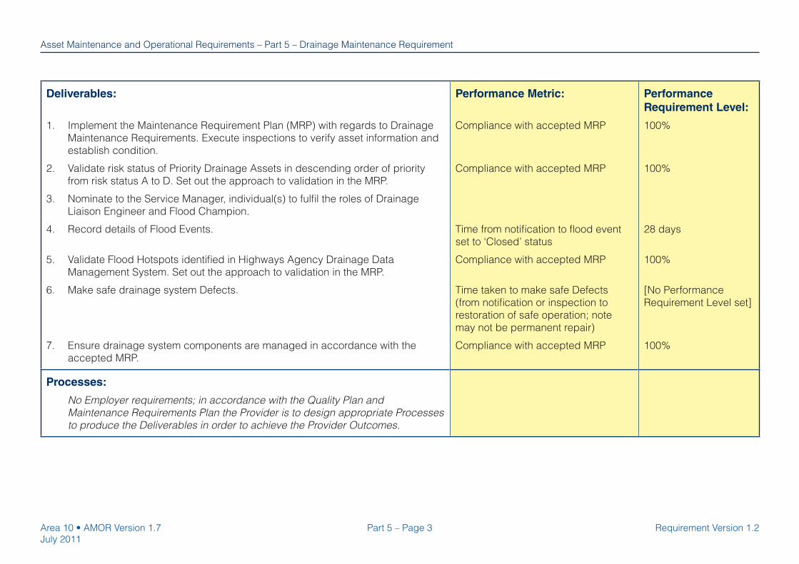
Part 5 – Page 3Area 10 • AMOR Version 1.7
July 2011
Requirement Version 1.2
Asset Maintenance and Operational Requirements – Part 5 – Drainage Maintenance Requirement
Deliverables:
1. Implement the Maintenance Requirement Plan (MRP) with regards to Drainage
Maintenance Requirements. Execute inspections to verify asset information and
establish condition.
2. Validate risk status of Priority Drainage Assets in descending order of priority
from risk status A to D. Set out the approach to validation in the MRP.
3. Nominate to the Service Manager, individual(s) to fulfi l the roles of Drainage
Liaison Engineer and Flood Champion.
4. Record details of Flood Events.
5. Validate Flood Hotspots identifi ed in Highways Agency Drainage Data
Management System. Set out the approach to validation in the MRP.
6. Make safe drainage system Defects.
7. Ensure drainage system components are managed in accordance with the
accepted MRP.
Performance Metric:
Compliance with accepted MRP
Compliance with accepted MRP
Time from notifi cation to fl ood event
set to ‘Closed’ status
Compliance with accepted MRP
Time taken to make safe Defects
(from notifi cation or inspection to
restoration of safe operation; note
may not be permanent repair)
Compliance with accepted MRP
Performance
Requirement Level:
100%
100%
28 days
100%
[No Performance
Requirement Level set]
100%
Processes:
No Employer requirements; in accordance with the Quality Plan and
Maintenance Requirements Plan the Provider is to design appropriate Processes
to produce the Deliverables in order to achieve the Provider Outcomes.

Area 10 • AMOR Version 1.7
July 2011
Part 5 – Page 4 Requirement Version 1.2
Asset Maintenance and Operational Requirements – Part 5 – Drainage Maintenance Requirement
Procedures:
1. Verify asset risk assessments and investigate risk status A Priority Drainage
Assets in accordance with guidance documentation hosted on the Downloads
section of www.haddms.com .
2. Drainage Liaison Engineer to be key point of contact for the Service Provider
for drainage related matters, and to assume responsibility for drainage surveys,
maintenance and renewals.
3. Comply with specifi cations for the drainage asset as set out in relevant parts of
MCHW Volumes 1, 2 and 3.
4. Manage to minimise pollution risk in accordance with HD 45.
5. Control drainage waste arisings such that they comply with legislation at the
point of disposal.
6. Record asset data as defi ned in the Provider contract and the Asset Data
Management Manual Provider Requirements.
Performance Metric: Performance
Requirement Level:
Asset Maintenance and Operational Requirements
Part 6 – Page 1Area 10 • AMOR Version 1.7
July 2011
Requirement Version 1.2
Part 6
Fences, Screens and Environmental Barriers
Maintenance RequirementVersion 1.2

Area 10 • AMOR Version 1.7
July 2011
Part 6 – Page 2 Requirement Version 1.2
Asset Maintenance and Operational Requirements – Part 6 – Fences, Screens and Environmental Barriers Maintenance Requirement
Part 6 – Fences, Screens and Environmental Barriers Maintenance Requirement
Scope:
All types of fences, screens and environmental barriers within the Area Network, inclusive of walls, stock proofi ng and wildlife fences.
Out of Scope: structural maintenance of fences, walls, screens and environmental barriers classifi ed as structures (i.e. >3m high).
Provider Outcomes:
1. Fences, screens and environmental barriers are safe and stable and fulfi l their
intended safety purpose.
2. Fences, screens and environmental barriers are managed to identify Defects
that would adversely impact upon their intended functional purpose.
Performance Metric: Performance
Requirement Level:
Deliverables:
1. Implement the Maintenance Requirements Plan (MRP) with regards to Fences,
Screens and Environmental Barriers Maintenance Requirements.
2. Execute inspections to identify Defects on fences, screens and environmental
barriers; and to verify, challenge and update ownership and maintenance
responsibilities, as defi ned in the Provider contract.
3. Where inspections or third parties identify adjacent landowner’s fences, screens
or environmental barriers as defective, immediately inform the responsible party
of their obligation to rectify Defects.
4. Rectify Defects which prevent the fence, screen or environmental barrier from
fulfi lling its intended safety purpose.
continues
Compliance with accepted MRP
Compliance with accepted inspection
regime.
Ownership and maintenance status
verifi ed at all inspected sites
Number of Defects related to safety
performance
Time taken to make safe Defects
(from notifi cation or inspection to
restoration of safe operation; note
may not be permanent repair)
100%
100%
100%
Zero
[No Performance
Requirement Level set]
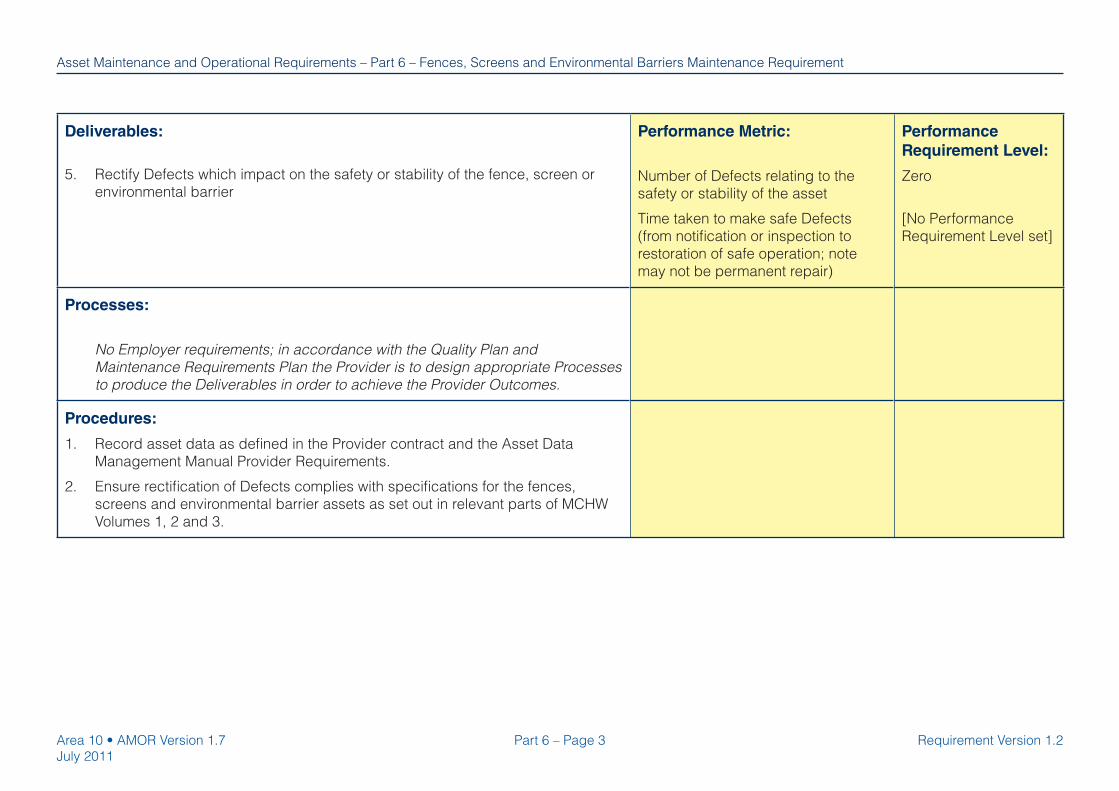
Part 6 – Page 3Area 10 • AMOR Version 1.7
July 2011
Requirement Version 1.2
Asset Maintenance and Operational Requirements – Part 6 – Fences, Screens and Environmental Barriers Maintenance Requirement
Deliverables:
5. Rectify Defects which impact on the safety or stability of the fence, screen or
environmental barrier
Performance Metric:
Number of Defects relating to the
safety or stability of the asset
Time taken to make safe Defects
(from notifi cation or inspection to
restoration of safe operation; note
may not be permanent repair)
Performance
Requirement Level:
Zero
[No Performance
Requirement Level set]
Processes:
No Employer requirements; in accordance with the Quality Plan and
Maintenance Requirements Plan the Provider is to design appropriate Processes
to produce the Deliverables in order to achieve the Provider Outcomes.
Procedures:
1. Record asset data as defi ned in the Provider contract and the Asset Data
Management Manual Provider Requirements.
2. Ensure rectifi cation of Defects complies with specifi cations for the fences,
screens and environmental barrier assets as set out in relevant parts of MCHW
Volumes 1, 2 and 3.

Page intentionally left blank.

Asset Maintenance and Operational Requirements
Part 7 – Page 1Area 10 • AMOR Version 1.7
July 2011
Requirement Version 1.1
Part 7
Geotechnical Assets Maintenance Requirement
Version 1.1

Area 10 • AMOR Version 1.7
July 2011
Part 7 – Page 2 Requirement Version 1.1
Asset Maintenance and Operational Requirements – Part 7 – Geotechnical Assets Maintenance Requirement
Part 7 – Geotechnical Assets Maintenance Requirement
Scope:
Geotechnical assets within the Area Network, comprising: embankment and cuttings on which the pavement and other assets are founded, and noise/
landscape bunds.
Out of Scope: physical works (inc. surveys and renewals) beyond short term management of safety critical Defects.
Provider Outcomes:
1. Potential Defects with geotechnical assets are identifi ed.
2. Defects are managed to minimise risks to road users.
3. Defects are managed to minimise risk of damage to other assets.
Performance Metric:
Length (in metres) of Temporary
Traffi c Management and/or temporary
road restraint systems in place on
the Area Network as a result of
geotechnical Defects
Performance
Requirement Level:
[No Performance
Requirement Level set]
Deliverables:
1. Implement the Maintenance Requirements Plan (MRP) with regards to
Geotechnical Assets, which will include the Geotechnical Asset Management
Plan (GAMP).
2. Develop a GAMP and submit to the Service Manager for acceptance. Upon
Service Manager acceptance implement the GAMP.
3. In accordance with the accepted GAMP (part of the overall MRP), develop and
implement a risk based Principal Inspection regime.
4. Make safe geotechnical asset Defects which adversely affect the stability,
integrity or operation of other highway assets, including but not limited to, paved
areas, drainage, communications cables.
Compliance with accepted MRP
Compliance with accepted GAMP
Compliance with accepted GAMP
Time taken to make safe Defects
(from notifi cation or inspection to
restoration of safe operation; note
may not be permanent repair)
100%
100%
100%
[No Performance
Requirement Level set]

Part 7 – Page 3Area 10 • AMOR Version 1.7
July 2011
Requirement Version 1.1
Asset Maintenance and Operational Requirements – Part 7 – Geotechnical Assets Maintenance Requirement
Processes:
No Employer requirements; in accordance with the Quality Plan and
Maintenance Requirements Plan the Provider is to design appropriate Processes
to produce the Deliverables in order to achieve the Provider Outcomes.
Performance Metric: Performance
Requirement Level:
Procedures:
1. Undertake activities in accordance with HD 41.
2. Manage risks in accordance with HD 22.
3. Record asset data as defi ned in the Provider contract and the Asset Data
Management Manual Provider Requirements.
Geotechnical Assets Maintenance Requirement - Hold Point
No. Hold Point Release Mechanism1. The Provider must prepare the Geotechnical Asset Management Plan in
accordance with HD 41 and submit to the Service Manager.
Written acceptance of the Geotechnical Asset Management Plan by the
Service Manager.

Page intentionally left blank.

Asset Maintenance and Operational Requirements
Part 8 – Page 1Area 10 • AMOR Version 1.7
July 2011
Requirement Version 1.3
Part 8
Lighting Maintenance Requirement
Version 1.3

Area 10 • AMOR Version 1.7
July 2011
Part 8 – Page 2 Requirement Version 1.3
Asset Maintenance and Operational Requirements – Part 8 – Lighting Maintenance Requirement
Part 8 – Lighting Maintenance Requirement
Scope:
Lighting equipment within the Area Network, specifi cally:
Luminaires, including their internal control electronics & electrics (including the photocell if fi tted) and lamp & refl ector. •
Belisha beacons and vertical wig wag signs at school or animal crossings. •
Lighting columns, including attached accessories, base or, if on a structure, mounting bracket. •
Road traffi c sign lighting, including lamp, luminaire, photocell, cables, ducting. •
Other access lighting such as pedestrian walkways, cycle ways and subway lighting. •
The electrical and optical elements of tall mast lighting systems (20m or more in height) and catenary lighting systems. •
Associated electrical supplies, including ducting, chambers, cables and feeder pillars and all switch gear, control equipment (including the •
photocell if fi tted), monitoring equipment and heaters therein.
Alternate energy sources such as solar panels or wind turbines etc. used for the purpose of road lighting or sign lighting. •
Any energy saving equipment, i.e. midnight switch off equipment and/or dimming equipment. •
Any power distribution cables downstream of the Distribution Network Operator (DNO) connection point. •
Out of Scope:
Lighting situated in road tunnels. •
Road traffi c signals. •
The non-electrical and structural elements of tall mast lighting systems (20m or more in height) and catenary lighting systems which are •
classifi ed as structures.

Part 8 – Page 3Area 10 • AMOR Version 1.7
July 2011
Requirement Version 1.3
Asset Maintenance and Operational Requirements – Part 8 – Lighting Maintenance Requirement
Provider Outcomes:
1. Lighting does not present a hazard to the road user, road worker or third parties.
2. Road lighting continues to fulfi l its intended purpose as an accident reduction
intervention.
3. Other lighting continues to fulfi l its intended purpose: road traffi c signs lighting
to highlight the location of a road traffi c sign, gantry lighting to highlight the
presence of the sign and to help read the sign, and other lighting (subway &
access) is to provide route guidance and hazard identifi cation.
Performance Metric: Performance
Requirement Level:
Deliverables:
1. Implement the Maintenance Requirements Plan (MRP) with regards to Lighting
Maintenance Requirements. This will include how lighting condition will be
maintained to the appropriate level over the following fi ve years. The Lighting
Maintenance section within MRP must be reviewed every two years.
2. Develop and implement an annual Lighting Asset Management Plan (LAMP)
to demonstrate how the Outcomes and Deliverables will be achieved in the
forthcoming year. Review this annually.
continues
Compliance with accepted MRP
Compliance with accepted annual
LAMP
100%
100%

Area 10 • AMOR Version 1.7
July 2011
Part 8 – Page 4 Requirement Version 1.3
Asset Maintenance and Operational Requirements – Part 8 – Lighting Maintenance Requirement
Deliverables:
3. In the annual LAMP develop and implement a risk based methodology to govern
the frequency of:
• road lighting electrical testing interval (5 years desirable - 6 years maximum);
• road lighting structural inspection interval (5 years desirable starting around
15 years after installation);
• road lighting optical maintenance (bulk lamp change and lens cleaning as a
minimum) - (5 years desirable minimum);
• electrical test, structural inspection & optical maintenance to be completed at
least once at each site during the initial term of contract.
4. Within 6 months of the Access Date, report on which parts of the asset are not
compliant with Deliverable 3. Report these fi ndings to the Employer.
5. Conduct Lighting Operational Performance Surveys (“scouting”) covering the
Area Network in order to verify achievement of Outcomes and performance
levels. Make all survey data available to the Employer. Execute a survey of the
Area Network during the last full week of: April, August, October, November,
January and February; report results to Employer by third working day of
following month. Execute a survey of the Area Network in the fi ve working days
following the 26th of December; report results to the Employer by the tenth
working day following the 26th December.
6. Make safe Defects.
7. Fit an appropriate lamp with a lifespan most closely matched to the target lamp
change interval both within and beyond the Provider contract term.
continues
Performance Metric:
Compliance with methodology in
accepted LAMP
Compliance with Deliverable 5
Time taken to make safe Defects
(from notifi cation or inspection to
restoration of safe operation; note
may not be permanent repair)
Compliance with lamp change regime
set out in Deliverable 3
Performance
Requirement Level:
100%
100%
[No Performance
Requirement Level set]
100%

Part 8 – Page 5Area 10 • AMOR Version 1.7
July 2011
Requirement Version 1.3
Asset Maintenance and Operational Requirements – Part 8 – Lighting Maintenance Requirement
Deliverables:
8. Maintain the energy effi ciency of lighting.
9. Maintain the effectiveness of energy saving equipment.
10. Re-use lamps with more than 25% of residual design life remaining.
11. The design life of each lighting scheme is not unduly or avoidably compromised
by the actions of the Provider.
12. Ensure the Employer meets its unmetered energy user obligations to the DNO.
13. Maintain the energy consumption inventory.
continues
Performance Metric:
Change in design energy
consumption of lighting before and
after maintenance intervention
Energy saving equipment is available;
Energy saving equipment is reliable.
Waste Electrical and Electronic
Equipment (WEEE) disposal records
Maintained monthly, defect free
Performance
Requirement Level:
Zero or less
99%
95%
The maximum number
of lamps that can be
disposed of during the
term of the Provider
contract is 120% of
the number of lamps
installed at the start of
the Provider contract.
100%

Area 10 • AMOR Version 1.7
July 2011
Part 8 – Page 6 Requirement Version 1.3
Asset Maintenance and Operational Requirements – Part 8 – Lighting Maintenance Requirement
Deliverables:
14. Manage and maintain road lighting to meet the following performance levels.
Where the dates to achieve performance levels in part c) overlap with those
required to achieve performance levels in part a), the performance levels in part
a) take precedence.
Note: With the agreement of the Employer, lighting performance levels may be
relaxed, when and where the Provider can clearly demonstrate that (this list is
inclusive):
I. There has been a failure by third parties (not subcontractors or equipment
suppliers) to facilitate or co-operate with fault rectifi cation, or,
II. The cause of the fault is such that fault rectifi cation requires substantial
remedial works requiring extensive planning and scheduling, or,
III. Access to site is not possible due to circumstances wholly outside the
control of the contractor, or,
IV. The Employer has requested that the fault is not rectifi ed, or,
V. A risk assessment has shown that the most appropriate action is to switch
off all or the vast majority of lights within the lighting scheme, or,
VI. Adverse weather conditions prevent setting out of traffi c management,
operation of equipment or effective fault rectifi cation.
continues
Performance Metric:
a) By last week in October:
i) Max. no. of sequential lamp
failures.
ii) Max. no. of failures per no. of
lamps, on
Motorways;
APTRs.
iii) Overall % lamp failures on,
Motorways;
APTRs.
b) During operation of Greenwich
Mean Time:
i) Max. no. of sequential lamp
failures;
Failure rectifi cation by next
scouting survey.
ii) Max. no. of failures per no. of
consecutive lamps;
Failure rectifi cation within 7 days.
iii) Overall % lamp failures on,
Motorways;
APTRs.
Performance
Requirement Level:
1
4 per 100
1 per 24
2%
2%
2
100%
6 per 20
100%
3%
3%
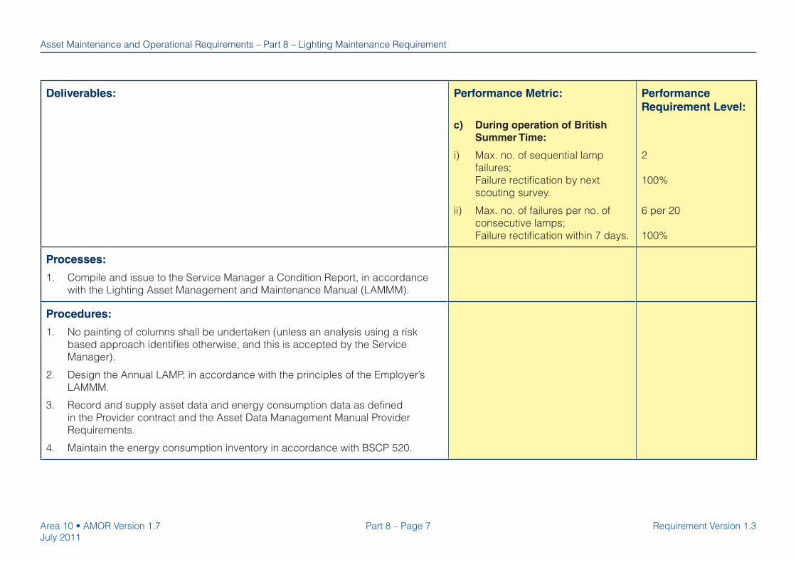
Part 8 – Page 7Area 10 • AMOR Version 1.7
July 2011
Requirement Version 1.3
Asset Maintenance and Operational Requirements – Part 8 – Lighting Maintenance Requirement
Deliverables: Performance Metric:
c) During operation of British
Summer Time:
i) Max. no. of sequential lamp
failures;
Failure rectifi cation by next
scouting survey.
ii) Max. no. of failures per no. of
consecutive lamps;
Failure rectifi cation within 7 days.
Performance
Requirement Level:
2
100%
6 per 20
100%
Processes:
1. Compile and issue to the Service Manager a Condition Report, in accordance
with the Lighting Asset Management and Maintenance Manual (LAMMM).
Procedures:
1. No painting of columns shall be undertaken (unless an analysis using a risk
based approach identifi es otherwise, and this is accepted by the Service
Manager).
2. Design the Annual LAMP, in accordance with the principles of the Employer’s
LAMMM.
3. Record and supply asset data and energy consumption data as defi ned
in the Provider contract and the Asset Data Management Manual Provider
Requirements.
4. Maintain the energy consumption inventory in accordance with BSCP 520.

Page intentionally left blank.

Asset Maintenance and Operational Requirements
Part 9 – Page 1Area 10 • AMOR Version 1.7
July 2011
Requirement version 1.3
Part 9
Paved Areas Maintenance Requirement
Version 1.3

Area 10 • AMOR Version 1.7
July 2011
Part 9 – Page 2 Requirement version 1.3
Asset Maintenance and Operational Requirements – Part 9 – Paved Areas Maintenance Requirement
Part 9 – Paved Areas Maintenance Requirement
Scope:
Paved areas, comprising: traffi cked areas, hard shoulders, footways, cycle tracks, bridle ways, paved pedestrian areas, hard-standing paved areas,
paved central reserves, traffi c islands and cross-overs, covers, gratings, frames, boxes, kerbs, edgings and preformed channels which fall within the
Area Network.
Provider Outcomes:
1. The paved area provides a safe and even surface for all road users.
Performance Metric: Performance
Requirement Level:
Deliverables:
1. In accordance with the accepted Maintenance Requirements Plan, develop
and implement a risk assessment methodology to determine the frequency
of inspections appropriate to location, asset type and condition. Execute
inspections to establish condition of paved areas.
2. Warn road users of the condition of the highway in relation to defects that could
cause danger to users of the highway.
3. Make safe Defects.
continues
Compliance with accepted MRP
Time taken to warn road users (from
verifi cation to implementation of
warning; note whether preventative or
re-active)
Time taken to make safe Defects
(from verifi cation to restoration of
safe operation; note may not be
permanent repair)
100%
[No Performance
Requirement Level set]
[No Performance
Requirement Level set]

Part 9 – Page 3Area 10 • AMOR Version 1.7
July 2011
Requirement version 1.3
Asset Maintenance and Operational Requirements – Part 9 – Paved Areas Maintenance Requirement
Deliverables:
continues
Performance Metric:
Trafficked Areas and Hard Shoulders:
Pothole > 20 mm depth and > 100 mm
diameter
Pothole > 150 mm diameter, or of >
depth than that of the surface course
thickness, or of > depth than 40mm.
Local Surface Deformation
(When measured under a 2m straight
edge)
Deformation > 20 mm
Deformation > 40 mm
Ironwork
Difference in level around ironwork
> 25 mm
All other areas:
Pothole > 20 mm depth and > 100
mm diameter
> 25 mm depth or > 150 mm
diameter
Performance
Requirement Level:
[No Performance
Requirement Level set]
Zero (within 24 hours of
verifi cation)
[No Performance
Requirement Level set]
Zero (within 24 hours of
verifi cation)
Zero (within 24 hours of
verifi cation)
[No Performance
Requirement Level set]
Zero (within 24 hours of
verifi cation)

Area 10 • AMOR Version 1.7
July 2011
Part 9 – Page 4 Requirement version 1.3
Asset Maintenance and Operational Requirements – Part 9 – Paved Areas Maintenance Requirement
Deliverables: Performance Metric:
All other areas:
Local Surface Deformation
(When measured under a 2m straight
edge)
Deformation > 20mm
Deformation > 25 mm
Trip Hazard
Any step change > 25 mm
Performance
Requirement Level:
[No Performance
Requirement Level set]
Zero (within 24 hours of
verifi cation)
Zero (within 24 hours of
verifi cation)
Processes:
No Employer requirements; in accordance with the Quality Plan and
Maintenance Requirements Plan the Provider is to design appropriate Processes
to produce the Deliverables in order to achieve the Provider Outcomes.
Performance Metric: Performance
Requirement Level:
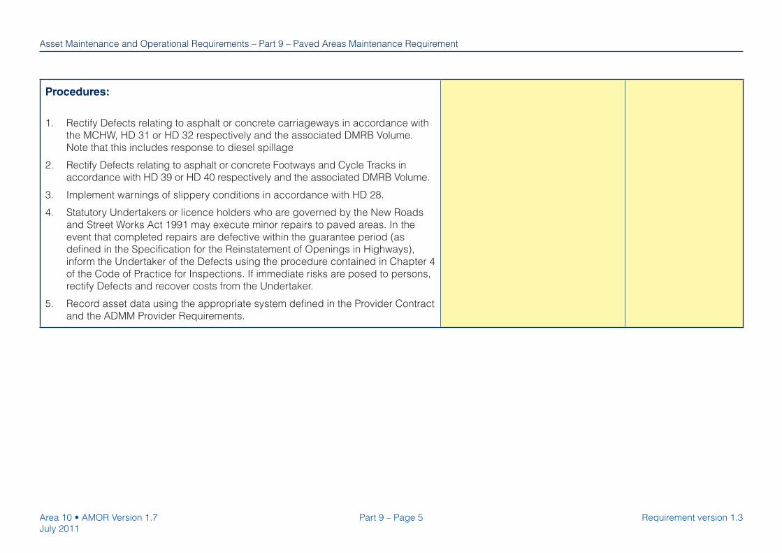
Part 9 – Page 5Area 10 • AMOR Version 1.7
July 2011
Requirement version 1.3
Asset Maintenance and Operational Requirements – Part 9 – Paved Areas Maintenance Requirement
Procedures:
1. Rectify Defects relating to asphalt or concrete carriageways in accordance with
the MCHW, HD 31 or HD 32 respectively and the associated DMRB Volume.
Note that this includes response to diesel spillage
2. Rectify Defects relating to asphalt or concrete Footways and Cycle Tracks in
accordance with HD 39 or HD 40 respectively and the associated DMRB Volume.
3. Implement warnings of slippery conditions in accordance with HD 28.
4. Statutory Undertakers or licence holders who are governed by the New Roads
and Street Works Act 1991 may execute minor repairs to paved areas. In the
event that completed repairs are defective within the guarantee period (as
defi ned in the Specifi cation for the Reinstatement of Openings in Highways),
inform the Undertaker of the Defects using the procedure contained in Chapter 4
of the Code of Practice for Inspections. If immediate risks are posed to persons,
rectify Defects and recover costs from the Undertaker.
5. Record asset data using the appropriate system defi ned in the Provider Contract
and the ADMM Provider Requirements.

Page intentionally left blank.

Asset Maintenance and Operational Requirements
Part 10 – Page 1Area 10 • AMOR Version 1.7
July 2011
Requirement Version 1.2
Part 10
Road Markings and Road Studs Maintenance
RequirementVersion 1.2

Area 10 • AMOR Version 1.7
July 2011
Part 10 – Page 2 Requirement Version 1.2
Asset Maintenance and Operational Requirements – Part 10 – Road Markings and Road Studs Maintenance Requirement
Part 10 – Road Markings and Road Studs Maintenance Requirement
Scope:
Road markings and road studs in all materials within the Area Network.
Provider Outcomes:
1. Road markings and road studs are safe and visible.
Performance Metric: Performance
Requirement Level:
Deliverables:
1. Implement the Maintenance Requirements Plan (MRP) with regards to Road
Markings and Road Studs Maintenance Requirements.
2. Manage deterioration of road markings and road studs such that they give effect
to regulatory provision in the Traffi c Signs Regulations and General Directions
(TSRGD).
3. Inspect the road markings and road studs to obtain asset inventory and
condition data; execute follow up inspections.
4. Correct or make safe all Category 1 Defects (as defi ned in TD 26).
Compliance with accepted MRP
Compliance with TD 26 inspection
frequencies
Compliance with TD 26 requirements
Time taken to make safe Defects
(from notifi cation or inspection to
restoration of safe operation; note
may not be permanent repair)
100%
100%
100%
[No Performance
Requirement Level set]
Processes:
No Employer requirements; in accordance with the Quality Plan and
Maintenance Requirements Plan the Provider is to design appropriate Processes
to produce the Deliverables in order to achieve the Provider Outcomes.

Part 10 – Page 3Area 10 • AMOR Version 1.7
July 2011
Requirement Version 1.2
Asset Maintenance and Operational Requirements – Part 10 – Road Markings and Road Studs Maintenance Requirement
Procedures:
1. Follow TD 26.
2. Record asset data as defi ned in the Provider contract and the Asset Data
Management Manual Provider Requirements.
Performance Metric: Performance
Requirement Level:

Page intentionally left blank.

Asset Maintenance and Operational Requirements
Part 11 – Page 1Area 10 • AMOR Version 1.7
July 2011
Requirement Version 1.2
Part 11
Road Restraint Systems Maintenance Requirement
Version 1.2

Area 10 • AMOR Version 1.7
July 2011
Part 11 – Page 2 Requirement Version 1.2
Asset Maintenance and Operational Requirements – Part 11 – Road Restraint Systems Maintenance Requirement
Part 11 – Road Restraint Systems Maintenance Requirement
Scope:
All vehicle restraint systems and pedestrian restraint systems within the Area Network, including: vehicle safety barriers, crash cushions, terminals,
transitions, pedestrian guard rails, vehicle parapets and pedestrian parapets on bridges and other structures.
Provider Outcomes:
1. Road restraint systems are managed and maintained to function in accordance
with their intended design and performance requirements.
Performance Metric: Performance
Requirement Level:
Deliverables:
1. Implement the Maintenance Requirements Plan (MRP) with regards to Road
Restraint Systems Maintenance Requirements, and within manufacturer’s
inspection specifi cations for proprietary systems. This will obtain asset inventory
and condition data and will identify Defects including, but not limited to:
a. Areas of corrosion, cracking, spalling or other material deterioration which
could affect achievement of the outcome;
b. Broken, loose or missing components;
c. Potential signs of fl uid and gas build up in metal parapets.
2. Make safe Defects.
continues
Compliance with accepted MRP
Defects present, not relating to
impact damage (no. of)
For each assessed Defect, difference
between suitable response path
nominated by following risk
assessment, and actual response
taken
Time taken to make safe Defects
(from notifi cation or inspection to
restoration of safe operation; note
may not be permanent repair)
100%
[No Performance
Requirement Level set]
Zero
[No Performance
Requirement Level set]

Part 11 – Page 3Area 10 • AMOR Version 1.7
July 2011
Requirement Version 1.2
Asset Maintenance and Operational Requirements – Part 11 – Road Restraint Systems Maintenance Requirement
Deliverables:
3. Maintain barrier tension in accordance with manufacturer’s recommendations,
or, in the absence of manufacturer’s recommendations (e.g. on non-proprietary
safety barrier systems), in accordance with BS 7669-3. Replace all post screws
when re-tensioning Tension Corrugated Beam (TCB) safety barriers.
Performance Metric: Performance
Requirement Level:
Processes:
No Employer requirements; in accordance with the Quality Plan and
Maintenance Requirements Plan the Provider is to design appropriate Processes
to produce the Deliverables in order to achieve the Provider Outcomes.
Procedures:
1. Where Defects result from vehicle impact, follow the risk based procedure Lane
Restrictions at Barrier Repairs (Appendix 11).
2. Rectify Defects in non-proprietary safety barrier systems in accordance with BS
7669-3.
3. Rectify Defects in proprietary road restraint systems in accordance with the
manufacturer’s recommendations.

Page intentionally left blank.

Asset Maintenance and Operational Requirements
Part 12 – Page 1Area 10 • AMOR Version 1.7
July 2011
Requirement Version 1.3
Part 12
Road Traffi c Signs Maintenance Requirement
Version 1.3

Area 10 • AMOR Version 1.7
July 2011
Part 12 – Page 2 Requirement Version 1.3
Asset Maintenance and Operational Requirements – Part 12 – Road Traffi c Signs Maintenance Requirement
Part 12 – Road Traffic Signs Maintenance Requirement
Scope:
Traffi c signs within the Area Network, including all posts, supports and fastenings; all bollards; mechanical variable message signs, together with
associated electrical equipment where appropriate.
Out of Scope:
The lighting of road traffi c signs (which are included in Lighting Maintenance Requirements); •
Structural aspects of road traffi c signs classifi ed as structures in BD 63 (which are included in Structures Maintenance Requirements); •
Management of soft estate to preserve road users’ visibility of road traffi c signs (which is included in the Soft Estate Maintenance •
Requirements);
Light emitting variable message signs (which are included in the Technology Management and Maintenance Manual); and, •
Proprietary Motorway Service Area signs. •
Provider Outcomes:
1. Road traffi c signs are safe and clearly legible.
2. Road traffi c signs give effect to regulatory provision.
Performance Metric: Performance
Requirement Level:
Deliverables:
1. Implement the Maintenance Requirements Plan (MRP) with regards to Road
Traffi c Signs Maintenance Requirements.
2. In accordance with TD 25, inspect road traffi c signs to obtain asset inventory
and condition data.
3. Manage identifi ed Defects.
continues
Compliance with accepted MRP
Inspection once per year.
Number of Category 1 Defects (as
defi ned in TD 25) present on the Area
Network
100%
100%
Zero

Part 12 – Page 3Area 10 • AMOR Version 1.7
July 2011
Requirement Version 1.3
Asset Maintenance and Operational Requirements – Part 12 – Road Traffi c Signs Maintenance Requirement
Deliverables:
4. Identify manufacturing faults or Defects falling within a sign’s warranty period
and proactively pursue warranty claims on behalf of the Highways Agency.
5. Remove signs ceasing to have effect and which are obsolete.
6. Clean sign faces and reference numbers.
Performance Metric:
Compliance with TD 25 cleaning
regimes
Performance
Requirement Level:
100%
Processes:
No Employer requirements; in accordance with the Quality Plan and
Maintenance Requirements Plan the Provider is to design appropriate Processes
to produce the Deliverables in order to achieve the Provider Outcomes.
Procedures:
1. Regulatory provision for Road Traffi c Signs is given in the Traffi c Signs
Regulations and General Directions (TSRGD), and includes those specially
authorised by the Secretary of State under Section 64 of the Road Traffi c
Regulation Act, signs ceasing to have effect as defi ned in Regulation 3, and
those which are obsolete as defi ned in TD 25.
2. Manage identifi ed Defects in accordance with TD 25.
3. Where repair or replacement of signs is required, execute this in accordance
with TD 25.
4. Clean signs in accordance with TD 25 and manufacturers’ instructions.
5. Record asset data as defi ned in the Provider contract and the Asset Data
Management Manual Provider Requirements.

Page intentionally left blank.

Asset Maintenance and Operational Requirements
Part 13 – Page 1Area 10 • AMOR Version 1.7
July 2011
Requirement Version 1.1
Part 13
Soft Estate Maintenance Requirement
Version 1.1

Area 10 • AMOR Version 1.7
July 2011
Part 13 – Page 2 Requirement Version 1.1
Asset Maintenance and Operational Requirements – Part 13 – Soft Estate Maintenance Requirement
Part 13 – Soft Estate Maintenance Requirements
Scope:
The semi-natural, improved / semi-improved and landscaped parts within the Area Network, including cultural heritage assets and hard landscaping
areas.
Provider Outcomes:
1. Soft Estate condition is managed and maintained to minimise risks to road users,
road workers and adjacent affected parties.
2. Soft estate is managed and maintained to protect and maintain designated and
Protected Habitats / Species, improved / semi-improved / landscaped parts.
3. Soft estate is managed and maintained to meet existing commitments to Public
Inquiries, Planning Consents, third parties, protection of Designated Sites
(International, National), or Protected Habitats / Species.
Performance Metric: Performance
Requirement Level:
Deliverables:
1. Develop and annually update Environmental Management Plan (EMP) and
submit to the Service Manager for acceptance.
2. Implement the Maintenance Requirements Plan (MRP) with regards to Soft
Estate Maintenance Requirements.
3. Maintain and preserve road users’ sight lines and stopping distances at
junctions, access points and bends.
4. Maintain and preserve road users’ visibility of road traffi c signs and signals.
5. Ensure illumination / lumination from lighting is not obscured.
continues
Compliance with accepted EMP
Compliance with accepted MRP
Number of validated claims relating
to soft estate not maintained in
accordance with Deliverables 1 to 14
100%
100%
Zero

Part 13 – Page 3Area 10 • AMOR Version 1.7
July 2011
Requirement Version 1.1
Asset Maintenance and Operational Requirements – Part 13 – Soft Estate Maintenance Requirement
Deliverables:
6. Preserve CCTV camera visibility splays.
7. Maintain soft estate to minimise risk of fi re hazards.
8. Maintain soft estate to facilitate safe access to technology equipment. This
includes but is not limited to roadside equipment cabinets and cable joint
chambers, cable troughs, CCTV camera sites, message sign sites, metrological
equipment.
9. Maintain soft estate to facilitate safe access to footways, cycle tracks, bridle
ways and paved pedestrian areas.
10. Minimise the risk of trees falling on traffi cked or pedestrian areas.
11. Manage the soft estate to minimise the spread or increase of instances of
injurious weeds.
12. Manage and maintain soft estate to minimise the risk of adversely affecting the
stability, integrity or operation of other highway assets.
13. Manage soft estate to meet existing landscape, amenity, screening functions
and/or other commitments where these have been raised by existing Public
Inquiries, Planning Consents, Protected Habitats / Species or Designated Sites
(International, National).
14. Maintain and update knowledge of semi-natural assets, improved / semi-
improved, landscaped, Protected Habitats / Species present or likely to be
present within the soft estate.
Performance Metric:
Compliance with Deliverables 1 to14
will be verifi ed by sample audits, as
specifi ed by the Service Manager
Performance
Requirement Level:
100%

Area 10 • AMOR Version 1.7
July 2011
Part 13 – Page 4 Requirement Version 1.1
Asset Maintenance and Operational Requirements – Part 13 – Soft Estate Maintenance Requirement
Processes:
No Employer requirements; in accordance with the Quality Plan and
Maintenance Requirements Plan the Provider is to design appropriate Processes
to produce the Deliverables in order to achieve the Provider Outcomes.
Performance Metric: Performance
Requirement Level:
Procedures:
1. Record asset data using the appropriate system defi ned in the Provider contract
and the Asset Data Management Manual Provider Requirements.
2. Develop the EMP in accordance with HA 108 and the Highways Agency
Environment Strategy and Managing our Approach to Environmental
Performance.
Soft Estate Maintenance Requirement - Hold Point
No. Hold Point Release Mechanism1. The Provider must prepare the Environmental Management Plan in
accordance with HA 108 and the Highways Agency Environment
Strategy and Managing our Approach to Environmental Performance
and submit to the Service Manager.
Written acceptance of the Environmental Management Plan by the
Service Manager.
Asset Maintenance and Operational Requirements
Part 14 – Page 1Area 10 • AMOR Version 1.7
July 2011
Requirement Version 1.3
Part 14
Structures Maintenance Requirement
Version 1.3

Area 10 • AMOR Version 1.7
July 2011
Part 14 – Page 2 Requirement Version 1.3
Asset Maintenance and Operational Requirements – Part 14 – Structures Maintenance Requirement
Part 14 – Structures Maintenance Requirement
Scope:
A civil construction within the Area Network, situated under, over or adjacent to the Strategic Road Network.
Structures include, but are not limited to:
Overbridges; •
Underbridges of enclosed length less than 150m; •
Subways of enclosed length less than 150m; •
Footbridges; •
Cycle bridges; •
Retaining Walls; •
Culverts with a clear span or internal diameter greater than 0.9m; •
Buildings; •
Structural maintenance of fences, walls, screens and environmental barriers >3m in height; •
Gantries, signs, lighting columns or catenaries, CCTV masts, classifi ed as structures in BD 63. •
Non-structural elements also included within the scope of this maintenance requirement include, but are not limited to:
Cross carriageway ducts, ducts through structures, technology equipment cabinets and all ancillary equipment (e.g. hoists, winches, covers). •
Out of Scope:
Transmission stations •
Provider Outcomes:
1. Structures and their constituent parts are managed and maintained to minimise
risks to road users.
Performance Metric: Performance
Requirement Level:

Part 14 – Page 3Area 10 • AMOR Version 1.7
July 2011
Requirement Version 1.3
Asset Maintenance and Operational Requirements – Part 14 – Structures Maintenance Requirement
Deliverables:
1. Implement the Maintenance Requirements Plan (MRP) with regards to Structures
Maintenance Requirements.
2. Execute Principal Inspections.
3. Execute General Inspections.
4. Identify where a need for Special Inspections exists; notify the Service Manager.
Upon Service Manager acceptance, execute Special Inspections.
5. Make safe Defects.
6. Review and update interim measures for the management of substandard
structures.
Performance Metric:
Compliance with accepted MRP
No. of structures inspected as per BD
63 frequencies
No. of structures inspected as per BD
63 frequencies
Time taken to make safe Defects
(from notifi cation or inspection to
restoration of safe operation; note
may not be permanent repair)
Performance
Requirement Level:
100%
100%
100%
[No Performance
Requirement Level set]
Processes:
No Employer requirements; in accordance with the Quality Plan and
Maintenance Requirements Plan the Provider is to design appropriate Processes
to produce the Deliverables in order to achieve the Provider Outcomes.
Procedures:
1. Execute Principal Inspections in accordance with BD 63.
2. Execute General Inspections and Special Inspections in accordance with BD 63.
continues

Area 10 • AMOR Version 1.7
July 2011
Part 14 – Page 4 Requirement Version 1.3
Asset Maintenance and Operational Requirements – Part 14 – Structures Maintenance Requirement
Procedures:
3. Manage sub-standard structures in accordance with BD 79.
4. Undertake maintenance in accordance with appropriate Parts of Volume 3 of
the DMRB, manufacturers’ instructions, and the relevant Structures Maintenance
Manual or Structures File.
5. Record asset data as defi ned in the Provider contract and the Asset Data
Management Manual Provider Requirements.
Performance Metric: Performance
Requirement Level:
Structures Maintenance Requirement - Hold Point
No. Hold Point Release Mechanism1. Where a need for Special Inspections exists, notify the Service Manager. Evidence held by the Service Manager that he has accepted execution
of Special Inspections.

Asset Maintenance and Operational Requirements
Part 15 – Page 1Area 10 • AMOR Version 1.7
July 2011
Requirement Version 1.1
Part 15
Sweeping and Cleaning Maintenance Requirement
Version 1.1

Area 10 • AMOR Version 1.7
July 2011
Part 15 – Page 2 Requirement Version 1.1
Asset Maintenance and Operational Requirements – Part 15 – Sweeping and Cleaning Maintenance Requirement
Part 15 – Sweeping and Cleaning Maintenance Requirement
Scope:
Sweeping and cleaning of:
All motorways and their surrounds within the Area Network; •
APTRs and their surrounds within the Area Network • only when listed in tables 15.1 or 15.2 in the Appendix to this requirement.
Cleaning and servicing of amenity facilities within the Area Network.
Out of Scope:
Initial response to Incidents involving or giving rise to debris, detritus or animal carcasses (see Incident Response requirements). •
Sweeping and cleaning of APTRs and their surrounds • not listed in tables 15.1 or 15.2 in the Appendix to this requirement.
Provider Outcomes:
1. The Area Network is predominantly free from litter, refuse and detritus.
2. Amenity facilities are safe and serviceable.
3. The functionality of the Area Network is not impeded by litter, debris, refuse,
detritus or animal carcasses.
4. Offensive graffi ti is managed to ensure that the adverse impact on road users of
the Area Network is minimised.
Performance Metric: Performance
Requirement Level:

Part 15 – Page 3Area 10 • AMOR Version 1.7
July 2011
Requirement Version 1.1
Asset Maintenance and Operational Requirements – Part 15 – Sweeping and Cleaning Maintenance Requirement
Deliverables:
1. Implement the Maintenance Requirements Plan (MRP) with regards to Sweeping
and Cleaning Maintenance Requirements.
2. Implement a risk based sweeping and cleaning intervention regime to mitigate
adverse affects of litter, refuse, or detritus on the appearance, stability, integrity
or operation of highway assets.
3. Implement a risk based sweeping and cleaning intervention regime to mitigate
adverse affects of debris and animal carcasses on the stability, integrity or
operation of highway assets.
4. Remove from sight offensive graffi ti on the Area Network.
5. Maintain Paved Areas (Carriageway, paved verges and paved central
reservations of motorways and APTRs) to grade A as defi ned in the Code of
Practice on Litter and Refuse.
6. Maintain Paved Areas (motorway and APTR roundabouts and lay-bys, approach
and slip roads) to grade A as defi ned in the Code of Practice on Litter and
Refuse.
continues
Performance Metric:
Compliance with accepted MRP
Within 24 hours
Restore to grade A from grade B or C
as defi ned in the Code of Practice on
Litter and Refuse within 28 days
Restore to grade A from grade D as
defi ned in the Code of Practice on
Litter and Refuse within 7 days
Restore to grade A from grade B or C
as defi ned in the Code of Practice on
Litter and Refuse within 14 days
Restore to grade A from grade D as
defi ned in the Code of Practice on
Litter and Refuse within 7 days
Performance
Requirement Level:
100%
100%
100%
100%
100%
100%

Area 10 • AMOR Version 1.7
July 2011
Part 15 – Page 4 Requirement Version 1.1
Asset Maintenance and Operational Requirements – Part 15 – Sweeping and Cleaning Maintenance Requirement
Deliverables:
7. Maintain all other parts of the Area Network (non paved) to grade B as defi ned in
the Code of Practice on Litter and Refuse.
8. Implement a risk based intervention regime to manage, maintain and clean
amenity facilities.
9. Directly notify other Highway Authorities responsible for sweeping and
cleaning on APTRs not listed in tables 15.1 or 15.2 in the Appendix to these
requirements, where it is apparent that they are not maintaining their sections of
the Area Network to an acceptable grade of cleanliness.
10. Deploy a Sweeping and Cleaning Rapid Response when instructed by the
Service Manager.
11. Empty litter bins prior to them over spilling.
Performance Metric:
Restore to grade B from grade C as
defi ned in the Code of Practice on
Litter and Refuse within 28 days
Restore to grade B from grade D as
defi ned in the Code of Practice on
Litter and Refuse within 7 days
Time since amenity area toilet block
last cleaned (live measure, report for
each applicable amenity area)
Within 24 hours of notifi cation
Performance
Requirement Level:
100%
100%
[No Performance
Requirement Level set]
100%
Processes:
No Employer requirements; in accordance with the Quality Plan and
Maintenance Requirements Plan the Provider is to design appropriate Processes
to produce the Deliverables in order to achieve the Provider Outcomes.
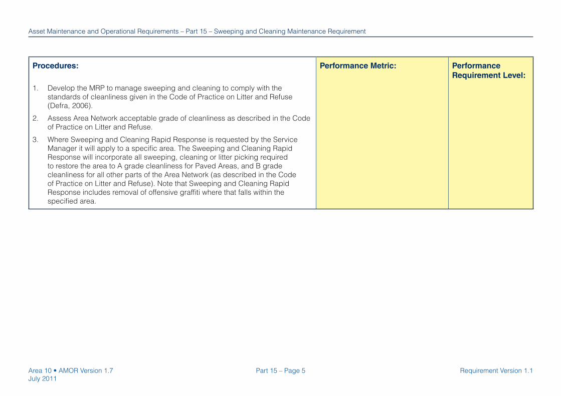
Part 15 – Page 5Area 10 • AMOR Version 1.7
July 2011
Requirement Version 1.1
Asset Maintenance and Operational Requirements – Part 15 – Sweeping and Cleaning Maintenance Requirement
Procedures:
1. Develop the MRP to manage sweeping and cleaning to comply with the
standards of cleanliness given in the Code of Practice on Litter and Refuse
(Defra, 2006).
2. Assess Area Network acceptable grade of cleanliness as described in the Code
of Practice on Litter and Refuse.
3. Where Sweeping and Cleaning Rapid Response is requested by the Service
Manager it will apply to a specifi c area. The Sweeping and Cleaning Rapid
Response will incorporate all sweeping, cleaning or litter picking required
to restore the area to A grade cleanliness for Paved Areas, and B grade
cleanliness for all other parts of the Area Network (as described in the Code
of Practice on Litter and Refuse). Note that Sweeping and Cleaning Rapid
Response includes removal of offensive graffi ti where that falls within the
specifi ed area.
Performance Metric: Performance
Requirement Level:

Page intentionally left blank.

Asset Maintenance and Operational Requirements
Part 16 – Page 1Area 10 • AMOR Version 1.7
July 2011
Requirement Version 1.1
Part 16
Tunnels Maintenance Requirement
Version 1.1

Area 10 • AMOR Version 1.7
July 2011
Part 16 – Page 2 Requirement Version 1.1
Asset Maintenance and Operational Requirements – Part 16 – Tunnels Maintenance Requirement
Part 16 – Tunnels Maintenance Requirement
Scope:
Tunnels within the Area Network, including associated mechanical and electrical equipment, and Supervisory Control And Data Acquisition (SCADA)
systems.
A highway tunnel is defi ned as any subsurface highway structure enclosed for a length of 150m or more, including associated access and service
infrastructure. The Operation and Maintenance Manual and the Network Information must be consulted to further defi ne the scope of responsibilities for
each tunnel.
Out of Scope:
Technology equipment as defi ned in the scope of the Technology Management and Maintenance Manual is the responsibility of the Regional
Technology Maintenance Contractor (RTMC).
Provider Outcomes:
1. Tunnels are managed, maintained and operated to ensure that they are safe and
structurally sound.
Performance Metric: Performance
Requirement Level:

Part 16 – Page 3Area 10 • AMOR Version 1.7
July 2011
Requirement Version 1.1
Asset Maintenance and Operational Requirements – Part 16 – Tunnels Maintenance Requirement
Deliverables:
1. Implement the Maintenance Requirements Plan (MRP) with regards to Tunnels
Maintenance Requirements.
2. Operate and maintain the tunnel in accordance with the Operation and
Maintenance Manual (O&MM).
3. Review and update the tunnel’s O&MM to include specifi c requirements for the
operation, emergency response, service activities, and to identify safety critical
components and ensure that these specifi cally operate as intended. Ensure
O&MM revisions and updates include operational risk assessments which will
determine the minimum safe operational requirements and associated minimum
intervention times when Defects are identifi ed. Update the O&MM following a
serious or disruptive Incident.
4. Execute Principal Inspections.
5. Execute General Inspections.
6. Make safe Defects which pose a hazard to road users.
7. Manage tunnel surfaces to maintain light refl ectance, and avoid accumulation of
toxic, corrosive and fl ammable deposits.
8. Conduct electrical inspection and testing.
Performance Metric:
Compliance with accepted MRP
Compliance with O&MM
Time taken to make safe Defects
(from notifi cation or inspection to
restoration of safe operation; note
may not be permanent repair)
Performance
Requirement Level:
100%
100%
[No Performance
Requirement Level set]
Processes:
No Employer requirements; in accordance with the Quality Plan and
Maintenance Requirements Plan the Provider is to design appropriate Processes
to produce the Deliverables in order to achieve the Provider Outcomes.

Area 10 • AMOR Version 1.7
July 2011
Part 16 – Page 4 Requirement Version 1.1
Asset Maintenance and Operational Requirements – Part 16 – Tunnels Maintenance Requirement
Procedures:
1. Inspect tunnels in accordance with BD 53.
2. Manage, maintain and operate tunnels in accordance with BA 72 and BD 78.
3. Manage pollutant levels within the tunnel in accordance with exposure limits set
out in the O&MM and BD 78. Note that exposure limits for oxides of nitrogen
(NOx) given in BD 78 are no longer applicable following withdrawal by HSE
of mandatory exposure limits relating to this pollutant. Instead, there is a
requirement to control exposure.
4. Comply with the Road Tunnels Safety Regulations 2007 in addition to BD 53
where they apply (i.e. to tunnels over 500m in length and which form part of the
Trans-European Road Network).
5. Record tunnels asset data in accordance with the appropriate system defi ned
in the Provider contract and the Asset Data Management Manual Provider
Requirements.
6. Conduct electrical inspection and testing in accordance with BS 7671 –
Requirements for Electrical Installations.
Performance Metric: Performance
Requirement Level:
Tunnels Maintenance Requirement - Hold Points
No. Hold Point Release Mechanism1. The Provider must review and update the Operation and Maintenance Manual for each
tunnel in the Area Network in accordance with the Tunnels Maintenance Requirements within
6 months of the Access Date, and submit this to the Service Manager.
Written acceptance of each Operation and
Maintenance Manual by the Service Manager.
2. The Provider must review and update the Operation and Maintenance Manual for each tunnel
in the Area Network in accordance with the Tunnels Maintenance Requirements within 6
months of the date that the Provider Contract ends, and submit this to the Service Manager.
Written acceptance of each Operation and
Maintenance Manual by the Service Manager.
3. Where a need for a Special Inspection exists the Provider must notify the Service Manager. Written instruction from Service Manager for the
Special Inspection.

Asset Maintenance and Operational Requirements
Area 10 • AMOR Version 1.7
July 2011
Appendix 2
Managing Network OccupancyOperational Requirement
Version 1.1
2.1 – Intelligence Led Approach to MNO
2.2 – Challenge to Individual Provisional Bookings
2.3 – Challenge to Individual Firm Bookings
2.4 – Optimisation of Occupancy
2.5 – Managing Network Occupancy – Departure Approval Form
2.6 – Risk Identifi cation and Categorisation of Events
2.7 – Abnormal Load Routeing and Management
2.8 – Temporary Traffi c Signs - Special Events
2.9 – Motorway Passes

Appendix 2.1 – Intelligence Led Approach to MNO Safe and effective network operation necessitates an intelligence-led approach in order to mitigate risks to Area Network availability whilst targeting delivery towards reducing costs. The approach to selecting suitable time periods for Occupancies must account for the additional delay above that typically expected on a given route at a given time. This acknowledges that levels of delay will vary with time across different parts of the Area Network according to demand. Area Network conditions must remain reliable within acceptable additional delays. This intelligence-led approach is required to ensure decisions are made about where and when to undertake Occupancy, accounting for the likely adverse impacts on road users and in determining Lowest Cost Practical Options (LCPOs) whilst maintaining the requirement to ensure conflicts with other Occupancies and Activities are managed appropriately. The LCPO approach to network Occupancy should start from the lowest cost and then consider whether traffic management arrangements are likely to introduce impacts which are disproportionate to the scale of anticipated savings. The key consideration is whether an Occupancy can be undertaken on the Area Network without creating unacceptable additional delay. An LCPO design is one which ensures:
(i) The minimum safe access requirements are maintained for the Occupancy
(ii) Additional delay is kept within acceptable levels for the categorisation of route Area Network
(iii) Additional delay is kept within acceptable levels on diversion routes on SRN
(iv) Additional delay is kept within acceptable levels on Local Authority network (as agreed with relevant Local Authorities)
(v) Compliance with all Highways Agency requirements in relation to all roadworks embargoes including Public and Bank Holidays and local operating regimes for Managed Motorways. In doing so, the potential for adverse publicity from activities where traffic management has to remain must be balanced against the benefit gained from undertaking Occupancies for the minimum duration at the most appropriate time commensurate with cost. Any specific local requirements will be instructed by the Service Manager.
. There are many locations/times on the network which typically exhibit delays. Occupancies can be considered during these periods, provided that the maximum additional delay introduced by traffic management does not exceed the acceptable level. Individual departures to the acceptable level will be considered by the Service Manager. These departures must be submitted using the Departure Approval Form at Appendix 2.5.

Appendix 2.2 – Challenge to Individual Provisional Bookings 1 The Provider must be aware that there will be times when Occupancies should not take
place on the Area Network. This must include adhering to all instructions relating to network Occupancy restrictions issued by the Service Manager.
2 Any departure from this requires the specific approval from;
Service Delivery Team Leader and/or The Service Manager and/or, The Regional Operations Board (ROB) where the impact of the Occupancy on the
Network is considered as likely to be significant by the Service Manager.
3 Where reductions in speed limits are proposed then the guidance contained in Chapter 8 of the Traffic Signs Manual must be followed. Where a reduction to the existing speed limit is greater than the recommended 20mph reduction then this must be approved as above.
4 For any approval required in points 2 or 3 above the Provider must complete the Departure Approval Form included at Appendix 2.5. The completed form must be submitted to the Service Manager for consideration and approval as appropriate.
5 The Provider must ensure that unacceptable additional delay is not caused by Occupancies
that affect traffic management considerations in relation to planned Events. 6 A list of Occupancy embargoes may be provided by the Highways Agency but if not must
be provided by the Provider and needs to be accepted by the Highways Agency. In addition this must include all instances where the Highways Agency has issued specific instructions about restricted Occupancy requirements.
7 The Provider must ensure that all provisional bookings have been challenged to establish
whether they are covered by 1, 2 ,3, 5 and 6 above and must notify the Occupancy or Activity promoter of any approved departure accordingly.
8 The Provider must make every endeavour to coordinate Occupancies/Activities on the Area
Network. This will require local considerations to be addressed. Where agreement is not reached the Provider must escalate the issue as follows:
a. Stage 1 Escalation – The Service Delivery Team Leader determines prioritisation
where the impact of that decision is isolated to within the Area Network. b. Stage 2 Escalation – The Service Manager determines prioritisation where the impact
of that decision is isolated to within the Region. c. Stage 2 Escalation - The ROB determines prioritisation where the impact of that
decision is cross-Regional. 9 The Provider must undertake an initial challenge to provisional booking.
The Provider must satisfy itself that:
a. The JTR Toolkit has been utilised where appropriate. b. The proposed Occupancy has been subject to challenge in respect to its impact on
delay utilising existing Highways Agency modelling tools. However, caution must be applied to ensure that the chosen modelling approach accounts for varying delays on the network for the relevant time of the day, rather than considering an average delay which risks significantly underestimating the additonal journey time that would be

c. The proposed duration appears reasonable when considering work outputs.
10 Where agreement cannot be reached between the Provider and the Promoter over issues
arising from the initial challenge in 9 above, then the Provider must escalate the issue as follows:
a. Stage 1 Escalation – The Service Delivery Team Leader determines prioritisation
where the impact of that decision is isolated to within the Area Network. b. Stage 2 Escalation – The Service Manager determines prioritisation where the impact
of that decision is isolated to within the Region.
c. Stage 2 Escalation – The ROB determines prioritisation where the impact of that decision is cross-Regional.
Challenges to Firm Occupancy Bookings are covered in Appendix 2.3. The Provider must also have regard to Appendix 2.3 when challenging individual provisional bookings to ensure that the overall programme of network Occupancy is considered.
Appendix 2.3 – Challenge to Individual Firm Bookings This challenge procedure is a significant element of delivering the MNO outcome to minimise the adverse impact of Occupancies/Activities on road users of the Area Network. The Provider must use its engineering expertise and historic data to challenge the method, timing and duration of all planned firm Occupancies. The degree of intensity of this challenge will vary in relation to the nature of the Occupancy requirement, but will always:
Check that the JTR Toolkit has been utilised where appropriate in arriving at the proposed Occupancy requirement.
Check that the estimated additional delay is acceptable using appropriate Highways
Agency modelling tools. Check the proposed method of work (from an engineering perspective, that it
recognises the MNO outcome in respect of minimising the adverse impact of Occupancies on road users of the Area Network).
Check the timing of the work; is it being done at the most efficient time of
day/month/year, considering all other activity bookings, commensurate with cost, including the use of all legislative powers available under the contract.
Take advantage of sharing opportunities (including with other Occupancy or Activity
promoters). Use expertise and historic performance data as a basis to ensure that the LCPO
approach has delivered appropriate duration. Ensure contingency plans are in place for potential changes to circumstances during
Occupancy e.g. curtailment, adjustment or abandonment of work.
The Provider must also have regard to Appendices 2.2 & 2.4 when challenging individual firm bookings.

Appendix 2.4 – Optimisation of Occupancy Optimisation means the shortest duration at most appropriate time for any Occupancy or group of Occupancies. Optimisation essentially commences with the challenges to provisional and firm booking requirements covered in Appendices 2.2 and 2.3. However this procedure covers the optimisation of the overall programme of Occupancies. It is an iterative process and the Provider must keep the overall programme of Occupancies under review at all times. The Provider must continually challenge and optimise the planned programme of Occupancies by some or all of the following as applicable: Table 2.4.1 Optimise Occupancies
Action Description Adjust timing of single Occupancy
Move Occupancy in terms of time of day/week/month to a more appropriate (LCPO) time
Adjust timing of multiple Occupancies
To increase or decrease separation/proximity between Occupancies
Combine Occupancies From both within the Provider and with third parties Further challenge to configuration and/or duration
Re-visit the challenge requirements covered by Appendix 2.3 - Challenge to Firm Bookings
Suspension of Occupancy Suspend the Occupancy for re-booking at a more appropriate (LCPO) time
This list is not exhaustive and the Provider must look to innovate and establish new tools and techniques to optimise all Occupancies. In doing so the Provider must contribute any such new and innovative ideas into the JTR Toolkit.

Appendix 2.5 - Managing Network Occupancy – Departure Approval Form This form is to be used where approval is required for departures to Occupancy requirements in accordance with Appendices 2.1, 2.2, 2.3 and 2.4 above
OCCUPANCY DETAILS SRW Closure No. Service Delivery Team
Select from list
Project/Scheme (including PIN) Brief description (to include type of work and what category in line with SRW)
Location Brief details of location (to include junctions roundabouts and slip roads)
Direction NorthboundEastbound
Southbound Westbound
Road Standard and Category Carriageway Select from list
Number of lanes Select from list
Road Category Select from list
Duration and Timing Estimated timing and duration of works
IMPACT OF PROPOSED TM ARRANGEMENTS
Traffic Management Arrangements Brief description of proposed lane closures and restrictions, scheme length and timing and duration (if different to above).
Is the TM a full closure? Select from list Does the TM create additional delay?If yes, specify max delay (ie additional minutes queuing time) and time period
Select from list
Does the TM create unacceptable additional delay? If yes, specify max RAG status and time period
Select from list
Are there any potential occupancy conflicts? If yes, provide explanation
Select from list
Are there any safety departures required? If yes, please specify
Will TM be on over bank holiday or during an embargo? If yes, please specify
ASSESSMENT OF LOWEST COST PRACTICAL OPTION (LCPO)
Is this the LCPO for the scheme? Select from list If yes and LCPO causes unacceptable delay, are alternative traffic management options available at no extra cost? Please specify impact of TM and explain
Select from list

why this has been discounted If no, why has a departure from LCPO requirements been requested? Please provide brief details, include explanation of why exceptions required. Include ratio of cost vs benefit to LCPO
Approval Submitted by (Service Provider)
Signature
Name Date
Checked by (HA Service Delivery Team Manager)
Signature
Name Date
Approved (Service Manager)
Signature Name Date
ROB Approval
Signature Name Date

Appendix 2.6 – Risk Identification and Categorisation of Events
1. Review all Events in relation to their potential to have an adverse impact on road users of the Area Network.
2. Assess Events against the following risk criteria in terms of the potential impact and likelihood to cause an adverse effect – review by High, Medium and Low risk potential utilising the current Risk Categorisation Matrix available from the Service Manager. Table 2.6.1
Group 1 Impact of traffic management arrangements (including promoter designed) Degree to which traffic management arrangements will adversely impact road users of the Area Network. Severity of potential queuing delay Based on review of traffic flow in conjunction with access arrangements. Combination effect with other concurrent Events Extent to which the effect of other concurrent Events could adversely affect the Event under scrutiny. Potential for other external situations to adversely affect the impact of the Event Consideration of past experience / hot spots and the Provider using local knowledge of the Area Network. The assessment of this risk must be evidenced by historical data. Managed Motorway(s) Events which may have an adverse impact on the effective operation of any affected Managed Motorway(s) within the Area or in any adjacent Area. Group 2 Location/proximity to Area Network The nature of the location of the Event and/or its proximity to the Area Network. Mode of access Extent of private vehicle usage against alternatives (e.g. public transport/park and ride).Season Potential effects of severe weather. Attendee profile Including geographical profile of attendees and characteristics of attendance e.g. numbers, short term visits, constant attendance. Maturity of Event and/or experience of Event promoter Extent to which past experience of managing the impact of the Event will affect the risk of impacting road users of the Area Network. Quality of access conditions to Event Degree to which the access/egress conditions could affect risk of impacting road users of the Area Network. Potential for event characteristics to change during Event Potential for changes to timing of Event or access/egress assumptions. Events with cross area/regional impact Knowledge of cross area/regional impact and the potential for the same if other external situations occur.
3. Based on a review of these impact criteria, the Provider must categorise Events using the
Risk Categorisation Matrix. An example of the Risk Categorisation Matrix is shown in Table 2.6.2.

Table 2.6.2
Impact Likelihood Category
Impact of TM arrangements (including promoter designed) Please Select Please Select
Severity of potential queuing delay Please Select Please Select
Combination effect with other concurrent events Please Select Please Select
Potential for other external intervening situation to adversely affect event Please Select Please Select
Managed motorways Please Select Please Select
Location / proximity to network Please Select Please Select
Mode of access Please Select Please Select
Season Please Select Please Select
Attendee profile Please Select Please Select
Maturity of event/promoter Please Select Please Select
Quality of access conditions to event Please Select Please Select
Potential for event characteristics to change during event Please Select Please Select
Events with cross Area/Regional impact Please Select Please Select
Event Title:
Event Reference Number:
Inherent Risk
Asset Maintenance and Operational Requirements
Overall Risk Category
Group 1
Group 2
Managing Network OccupancyRisk Categorisation Matrix
Risk Criteria Owner
Run
Reset
4. Obtain input to categorisation from the EPO, the Service Manager and the RCC and also
obtain acceptance of categorisation by the EPO. 5. Update monthly including re-categorisation as required. 6. All Risk Categorisation Matrices must be retained by the Provider.
The categorisation of risk for an Event accounts for the potential of the Event impacting adversely on road users of the Area Network. This enables the Highways Agency to determine those Events with the biggest potential of causing an adverse impact and therefore requiring the greatest level of management input. The original categorisation of the Event will remain irrespective of any subsequent mitigation measures identified and implemented by the Provider. If the Provider or the EPO become aware of any other risk particular to an Event that could increase the categorisation of risk of that Event then that increased categorisation must be applied
Appendix 2.7 Abnormal Load Routeing and Management General The routeing of Abnormal Indivisible Loads on the Network is managed by the Highways Agency’s Abnormal Indivisible Loads (AIL) Team. Abnormal Indivisible Loads are those which cannot, without undue expense or damage, be divided into two or more loads for the purpose of carriage on the Network. The movement of these loads is governed by Regulations, including the Road Traffic Act 1988, and DMRB standards BD86 and BD21. Associated policy mandated by that document is included in this Appendix. BD86 gives guidance for the determination for Vehicle Ratings and Reserve Factors for highway bridges and structures that indicate the load carrying capacity of structures to support Special Type General Order (STGO) and Special Order (SO) vehicles. BD86 is used in conjunction with BD21 which refers to the Authorised Weight (AW) Regulations, and should be utilised for the routeing of abnormal or indivisible loads on the Network. The categorisation of road vehicles is included in BD86 but they have been reproduced here for ease of reference:
(a) Vehicles complying with The Road Vehicles Construction and Use (C&U) Regulations and Authorised Weight (AW) Regulations.
This group includes cars, light goods vehicles, and rigid and articulated heavy goods vehicles up to a gross weight of 44 tonnes. These vehicles are covered by the C&U and AW Regulations and are not subject to permit and notification requirements. The effects of these vehicles are assessed in accordance with BD21.
(b) Vehicles complying with The Road Vehicles (Authorisation of Special Types)
General Order (STGO Regulations). This group includes vehicles that do not comply with the AW Regulations such as those
used for the carrying or drawing of abnormal indivisible loads. Notifications of movements of these vehicles are required in accordance with STGO Regulations. The effect of these STGO vehicles must be assessed in accordance with BD86.
(c) Special Order (SO) Regulations.
This group includes vehicles that do not comply with the AW or STGO Regulations
and is covered by Section 44 of the 1988 Road Traffic Act. Abnormal Indivisible Load Special Order Process There are three stages to the process as follows:
Stage 1: SO Consultation Stage – BE 16 Application Approval Stage 2: 5 Day Notification Stage Stage 3: SO 60 Minute Notification Stage Process flow charts detailing the roles each of the stakeholders, including Providers, discharges for Stage 1 to 3 are included at Tables 2.7.4 to 2.7.6 respectively.
The roles of the Provider, which he must assume and discharge, are further explained in Tables 2.7.1, 2.7.2 and 2.7.3.

Table 2.7.1 – Stage 1: SO Consultation Stage – BE 16 Application Approval:
Process Stage Role Responsibility Timescale
To receive provisional SO route information from AIL Team via electronic AIL postbox.
Provider must have a predetermined electronic AIL postbox in operation to allow the receipt and passing of SO information to the AIL Team.
To assess provisional load against structural capacity along the proposed SO route.
Provider must undertake structural capacity assessment along the proposed SO route in accordance with BD86 or as otherwise agreed with the Highways Agency Technical Approval Authority (TAA).
To provide the AIL Team with comments on any potential road space booking or network Occupancy conflicts.
Provider must assess the provisional SO route and timeframe using Scheduled Roadworks (SRW) as well as any other available source of network information.
To return all comments following structural assessment and Occupancy checks to the AIL Team.
Structural assessments and Occupancy checks must be completed by the Provider within timescales prescribed by the AIL Team. All comments must be returned (including nil returns) to the AIL Team by e-mail.
6 weeks
Identify any need for detailed structural assessment or Technical Approvals
Provider must: Inform the AIL Team of the requirement for additional technical approval at the soonest opportunity; provide information as to type of assessment or approval required as well as approximate timescale implications, and; administer detailed assessments or Technical Approvals on behalf of the haulier in accordance with existing procedures.
Up to 10 weeks*
Provide any further assistance or information as requested by AIL Team
Provider must respond to requests as soon as reasonably practicable and must provide any assistance according to AIL Team request Task dependant
Sta
ge 1
: SO
Con
sulta
tion
Sta
ge B
E 1
6 A
pplic
atio
n A
ppro
val
Take receipt and file all approved SO permit and route information
Provider must receive SO permit and route information via electronic AIL postbox and must file all information in accordance with existing procedures to facilitate future reference.
2 days*
* timescales will vary

Table 2.7.2 - Stage 2: 5 Day Notification Stage
Process Stage Role Responsibility Should a Provider receive a 5 Day Notification Stage directly from a haulier they are to advise the National Traffic Control Centre (NTCC) at their soonest possible opportunity
The Providers must provide the NTCC with all haulier 5 Day Notification information.
To receive 5 Day Notifications from NTCC via electronic AIL postbox.
Provider must have a predetermined electronic AIL postbox in operation to allow the receipt and passing of SO information to the NTCC.
To review current structural capacity along the approved SO route
Provider must undertake structural capacity review along the approved SO route. Load capacity assessments of structures for proposed SO vehicle movements must be subject to Technical Approval procedures in accordance with BD2.
To return all comments following structural assessment to the NTCC.
Provider must complete structural assessments checks within timescales prescribed by the NTCC and must return all relevant comments (including nil returns) to the NTCC by e-mail
To provide the NTCC with comments on any road space booking or network Occupancy conflicts
Provider must review the approved SO route and timing against current Scheduled Roadworks (SRW) entries as well as any other available source of network information. The Provider must also complete road space Occupancy checks within timescales prescribed by the NTCC and must return all relevant comments (including nil returns) to the NTCC by e-mail.
To create an SO movement related Event (X) entry in SRW
Provider must include all relevant SO movement details to SRW . The HA SO permit number must be entered into a SRW field that can be viewed by the NTCC for referencing purposes. Any ongoing management and update of SO SRW entries must be done in accordance to existing procedures.
5 D
ay N
otifi
catio
n S
tage
Provide any further assistance or information as requested by the Area Performance Team (APT).
Provider must respond to requests as soon as reasonably practicable and must provide any assistance according to Service Manager requests.

Table 2.7.3 - Stage 3: 60 Minute Notification Stage
Process Stage Role Responsibility
60 M
inut
e N
otifi
catio
n S
tage
Provide any further assistance or information as requested by the Regional Control Centre (RCC).
Providers Network Control Centre (NCC) (or equivalent) must respond to requests as soon as reasonably practicable and must provide any assistance according to RCC requests.

Detailed Structural Assessments and Technical Approval
The effects of STGO vehicles must be assessed in accordance with BD86.
For SO Vehicle Movements the following requirements apply unless expressly stated otherwise in the Provider’s contract:
(i) Load capacity assessments of structures for proposed vehicle movements, other than those using ESDAL screening, must be subject to Technical Approval procedures in accordance with BD2.
(ii) The Provider must provide an estimate of the costs of assessment of structures for route clearance to the Service Manager.
(iii) The estimate of cost of assessments of structures will be forwarded by the Service Manager to the applicant applying for a route for a SO vehicle movement. A suitable letter template is included in this Appendix. The Service Manager will advise the Provider to undertake the assessments once confirmation has been received by the Provider that costs will be met by the movement route applicant.
(iv) The applicant will be given a copy of the Assessment certificates for Load Assessments for which he has paid.
(v) On completion of appraisal of the route for a proposed SO Vehicle movement the Provider must notify the AIL Team of the suitability of the route using the form included in this Appendix.
Electronic Service Delivery for Abnormal Loads The ESDAL website is designed to help haulage companies plan their journeys when moving abnormal loads. The system provides an online mapping tool to enable hauliers to plot their route and then automatically notifies the details to the relevant road owner, structure owner and police. The website has been developed for the Highways Agency by Serco Integrated Transport and is designed for all parties involved in moving abnormal loads. ESDAL provides an automated route appraisal for all stakeholders and allows structure owners to manage structure data online by amending or adding structure attributes. They can also add constraints, such as roadworks, special events or local restrictions. Police, road and structure owners can also collaborate with a notifying haulier online providing feedback to a haulier if their route is unsuitable. It is recommended that this free service is used by all Providers. Those who wish to find out more about ESDAL, or register their details online, should visit the website: www.esdal.com

Table 2.7.4 – Abnormal Indivisible Load Special Order Process - Stage 1

Table 2.7.5 – Abnormal Indivisible Load Special Order Process - Stage 2

Table 2.7.6 – Abnormal Indivisible Load Special Order Process - Stage 3


SPECIAL ORDER MOVEMENTS Notification of suitability of route with respect to the load capacity of structures. HA reference: Maintenance Area: Movement reference/name: Description of route in Area: Description of Vehicle Train considered: [may be attached as a separate sheet – this would include wheel layout of the vehicle train, gross weights of vehicle and tractors, tyre contact areas, wheel and axle weights, etc] Results of Assessment: [list all structures affected by the route] Structure Name Structure Number Pass/Fail Comments [Include date of assessment, note of
critical elements, any cautions/conditions that apply. These might include vehicle speed, coincident loads, position of vehicle on carriageway etc]
I confirm that the above assessments have been carried out in accordance with HA procedures including those for Technical Approval. The vehicle may pass* / not pass* over this route subject to any conditions in the comments for each structure [* delete as appropriate] and subject to the general cautions and conditions given below: [List all comments / cautions / conditions that apply generally to the proposed route] Signature: Bridge Manager Name: Date: Provider: NOTES 1 This form is to be completed by Provider. 2 The above results only apply to the movement being considered based on the assessment
standards and the condition of the structure at the time this movement request was considered and other conditions noted against each structure. No assumptions shall be made regarding any similar movements along this route, which will each require a further application for agreement.

3 This form shall be faxed and posted to the Regional HA Abnormal Indivisible Loads
Administrator/regional business management team for the Area concerned. 4 The Highways Agency’s Abnormal Indivisible Loads Administrator shall attach this form to
the Weight Certificate required by HA internal procedures before submitting it to the Service Manager for signature.
5 The Bridge Manager is the person named in the Provider’s QA procedures as responsible
the management of all structures within the Network

Standard text of letter to be sent to Movement route applicant by the Highways Agency Dear Sir, [Insert here the unique name by which the abnormal load movement is known] STRUCTURAL ASSESSMENT COSTS FOR AREA [ Insert HA Area Number or DBFO details] Set out below the terms on which the Highways Agency are prepared to instruct [Name of Provider] to carry out the bridge assessments described in the Schedule attached hereto associated with the Special Order movement referred to above. 1. [Name of Company (the Movement route applicant)] will pay all costs, howsoever arising,
incurred by [Name of the Maintenance Provider] on behalf of the Highways Agency in connection with the carrying out the bridge assessments including administrative and professional costs and any value added tax. [Name of Company (Movement route applicant)] will on accepting the terms of this letter pay an estimate of the costs in the sum of £[……..] to the Highways Agency within 14 days of the date of this letter.
2. On completion of the assessments [Name of the Maintenance Provider] will certify the costs
incurred and, if the sum certified exceeds £ -----.-- [Name of Company (Movement route applicant)] will pay the Highways Agency the difference within 14 days of the date of the certificate, but if the sum certified is less than £ -----.-- the Highways Agency will refund the difference to [Name of the Company (Movement route applicant)] within that period.
3. The certificate of costs provided in accordance with paragraph 2 above shall be final, unless an error by the Maintenance Provider is shown to have been made. I shall be grateful if you would indicate [your company’s or the Company's] acceptance of the foregoing terms by signing and returning to me the enclosed copy of this letter with the attached schedule and plan / drawing.

Yours faithfully [Name of Company (Movement route applicant)] hereby accepts the terms and conditions set out in the above letter and requests the [Name of the Maintenance Provider] acting on behalf of the Highways Agency to carry out the assessments. Signed ……………………………………………. Director Date …………………………………. Schedule The assessments comprise [List the assessments to be undertaken by the Provider] 1.......... 2........... 3...........

APPENDIX 2.8 Temporary Traffic Signs - Special Events Introduction This Appendix refers to granting permission for the Automobile Association and others to erect temporary signs on the Network to notify of special Events. Policy Current policy is set out in the Department of Transport Network Management Advisory Leaflet entitled “Provision of Temporary Traffic Signs to Special Events”, dated May 1993. Interpretation of Note 2 in the Code of Practice for the erection of temporary traffic signs to special events is that, in the case of motorways, agreed temporary signs must only be erected by organisations meeting the training and operational requirements as detailed in the Code of Practice or by the Provider. On other trunk roads, however, there is no reason to prevent other reputable organisations from carrying out the work providing they comply with the general requirements in the leaflet. A code of practice for the erection of temporary traffic signs to special Events is included in this Appendix.. The Code of Practice for the erection of temporary traffic signs to special events details the duties of all those parties involved in erecting temporary traffic signs for Events. In order for the process to be effective, including ensuring that Sign Erectors are competent and have appropriate insurances (details included in this Appendix), there are some key duties for Providers. Providers must: Review the Event organisers proposals and ensure that proposals are compliant with
Standards, do not conflict with works planned by Provider and confirm that the sign location, layout, size and other details are acceptable. Address arrangements for Event organisers informing Provider of any changes and obtaining agreement of change with Provider
Confirm that training of Sign Erectors is compliant with the requirements of National Highways Sector Scheme 12B, or alternatively to 12A. In addition, both operatives and supervisors shall be aware of, and comply with where relevant, any other guidance, code of practice or advice note.
Confirm that Sign Erectors are in possession of Motorway Passes and processing applications for Motorway Passes presented by the parties involved in erecting of the temporary signs.
Ensure that the Insurance provided by the parties involved in the signage works is compliant with requirements
Agree arrangements for maintenance and removal of the signage with other parties Agree arrangements for inspection of signage and removal by Provider in the Event of an
emergency or when required to do so by the police or Highways Agency (together with agreement on recharging of Providers costs with Sign Erectors)
Agree arrangements for recovery of reasonable costs incurred by Provider with Event organisers

Code of Practice for the erection of temporary traffic signs to special Events General 1. Temporary signs should be provided only for Events expected to attract a considerable
volume of traffic from outside the local area and where there is adequate car parking for vehicles directed to the Event. They should not be used on routes where there are already permanent local direction or tourist signs to the site, although for some major Events it may be desirable to indicate other routes to assist traffic management. Signs should not normally be erected more than 48 hours before an Event or retained more than 48 hours after it has ended.
2. The signs must comply with the provisions of the Traffic Signs Regulations and General
Directions (currently set out in regulation 53 of the 2002 Regulations) and must give clear information about the route to be followed in a size appropriate to the speed of traffic.
3. The badge of the road user organisation erecting the sign may be included. Commercial
names of Event sponsors should not be included unless similar Events in the same areas at the same time make such identification necessary for traffic management purposes. Dates and times should not normally be included since the signs are not intended to advertise an Event but are for people who know about it and need guidance to the site. Such information may however be included if the traffic authority considers it would be helpful to other road users to have advance information about likely congestion and is satisfied that it would not make signs too complicated to be easily legible and so endanger road safety
4. The design, construction, mounting and location of signs should be in accordance with the
advice given in the Traffic Signs Manual (TSM) Chapter 8 Sections D4 (Design) and O4 (Operations). The signs should be built to sound engineering principles and be of robust construction but the materials used need not be as durable as those used for permanent or portable signs. The fixings used must not damage the posts to which signs are fixed.
5. Signing proposals should be put to the appropriate traffic authority in time for them to be
given proper consideration and for the police to be consulted where necessary. This should normally be at least 13 weeks before the Event. Proposals should include information about the nature of the Event, the expected number of visitors and the provisions for car parking. The distance from which signs should be provided and the number of routes to be indicated depends on the nature of the Event and the volume of traffic anticipated but once signing has commenced adequate continuity should be provided along the route. Signing for up to 5 miles or from the nearest A or B road should usually be adequate. More extensive signing may be appropriate for Events which are expected to attract very large numbers of visitors (e.g. major air shows) The traffic authority is the final arbiter of the signing appropriate for any Event and may remove or re-site any signs which have not been approved at the cost of the body which erected them.
6. It is very rarely appropriate for signs to Events to be erected on motorways. Only where
there are traffic management benefits for the Highways Agency should fixed temporary signs be used on the motorway network e.g. such as where traffic is required to use a different junction than the one normally used to access the location of the Event, or where specific vehicle or road user types have to use different junctions.
7. Organisations erecting temporary traffic signs on the highway must take all necessary
measures to avoid danger to the public or obstruction of traffic during the operation as specified in TSM Chapter 8 and the booklet "Safety at Street Works and Roads Works a Code of Practice". These organisations are responsible for the cost of making good any damage to street furniture and Statutory Undertakers' equipment resulting from the erection of the signs and must have adequate public liability insurance cover. They will be required to indemnify the traffic authority against any claim arising out of an accident alleged to have

been caused by the inadequacy of a temporary sign whether in siting, visibility, insecure mounting or other cause.
8. The organisation erecting temporary traffic signs shall indemnify and keep indemnified the
Secretary of State, his servants and agents in respect of any claims or losses of any person (including, for the avoidance of doubt, the organisation and the Secretary of State) which may arise out of, or in the course of or in connection with the operations.
Strategic Road Network (Safety) 9. Working on the Strategic Road Network potentially exposes workers to significant extra
risks than those posed on other roads. Therefore, only organisations which can show an adequate level of training and competence will be give permission to place signs on motorways. Other organisations may have any agreed signs placed on the Strategic Road Network by the relevant Provider.
10. For both road worker and road user safety it is imperative that any operative on the the
Strategic Road Network must have sufficient training to be able to complete their work. For those organisations with permission to place signs on a motorway all operatives which will be required to be on a live carriageway at any point of the work must be trained to the relevant level of National Highways Sector Scheme 12B, or alternatively to 12A. In addition, both operatives and supervisions shall be aware of, and comply with where relevant, any other guidance, code of practice or advice note. This includes, but is not limited to, the documents listed in paragraph seven above as well as Departmental Interim Advice Note 115 and ‘Guidance for Safer Temporary Traffic Management - Issued 2002’.
11. As most motorways have three or more lanes the readability of temporary signs at longer
viewing distances is of greater importance than other roads. It is vital that the design and manufacture of signs is sufficient to give an acceptable reading time for drivers in the outside lanes. To ensure this the staff within organisations directly involved with the manufacture and/or design of the signs are required to meet the training and competency levels set in the National Highways Sector Scheme 9A.
Strategic Road Network (Operational) 12. There will be a need to synchronise the operations of those erecting the Event signs with
the operations of the Provider and others carrying out work on the the Strategic Road Network. As part of those discussions the following will need to be agreed
Sign location, layout, size and other signage details Insurance provision Training of operatives involved in accordance with paragraph 10 above and, if required,
to meet requirements of the Provider Arrangements for sign removal including provision for removal by the Provider if not
removed by Sign Erector by an agreed date and emergency removal or repair by the Provider if found to be in an unsafe condition or instructed to do so by police or Traffic Officer Service ( and agreement on recovery of Providers costs with Sign Erector)
Arrangements for informing and updating the Provider, Traffic Officer Service and police on progress in placing, maintaining and removing signage.
If there are any site specific risks, the Provider may require the supply of a method statement for sign placement, maintenance and removal together with associated works. No signage or associated works is permitted until the method statement has been accepted in writing by the Provider.
If the Provider or Event organisers wishes to make use of the either the Highways Agency’s portable or fixed VMS to help sign an Event then this should be carried out in accordance with AMM09 and through agreement with the National Traffic Control Centre (contactable at [email protected])

13. Operatives employed by Sign Erector or 3rd parties in the provision of the signs will be required to have Motorway Passes. All applications for passes should be submitted to the Provider so that they remain aware of operatives working on their Network. The Provider is expected to work with due haste to allow the timely placement of signs.
14. An agreement on placing signs is required under Section 65 of the Road Traffic Regulation
Act 1984 prior to permission being given to place signs on the network. 15. The Provider must advise the Service Manager that specific permission to Section 65 must
be given. 16. Temporary traffic signs to special Events shall only be placed on Managed Motorways or
where roadworks are present by the Provider or the main works contractor. Alternative, advanced, signing may be appropriate.
17. Costs incurred by the Provider in agreeing location, layout and signage details is covered
by the existing contract. However any costs incurred by the Provider as a result of either placing signage or overseeing the placement of signage (including maintenance and removal) works on the motorway may be reclaimed from the Sign Erector or 3rd party requesting the temporary traffic signs to special Events.

Insurance details for Erectors of Temporary Traffic Signs to Special Events Details of level of insurance to be provided by Motoring/Signing organisation shall be as follows. Definitions
Sign Erector the organisation proposing to place Temporary Special Event Signs on the Strategic Road Network where the Secretary of State is the Highway Authority
Access Date Date from which any access to the Strategic Road Network is required in order to carry out work associated with placing or removal of signs
Closure date Date when all Event signs and any associated temporary arrangements are removed from the Strategic Road Network.
Placement Period Period between commencement of any works associated with the placement of the Temporary Event Signs and the completed removal of all Temporary Event Signs and any associated arrangements
Risks and insurance The amount of the minimum limit of indemnity for insurance in respect of loss of or damage to property (except the Network, Materials and Equipment) and liability for bodily injury to or death of a person (not an employee of the Provider) caused in connection with this contract for any one Event is £40,000,000 (Forty Million Pounds). The amount of the minimum limit of indemnity for insurance in respect of death of or bodily injury to employees of the Provider arising out of and in the course of their employment in connection with this contract for any one Event is £10,000,000 (Ten Million Pounds). The amount of the minimum limit of indemnity for insurance in respect of claims made against the Provider arising out of his failure to use the skill and care normally used by professionals providing services similar to the Services is £5,000,000 (Five Million Pounds). The minimum limit of indemnity applies in the aggregate in any one period of insurance for claims arising out of pollution or contamination. The Sign Erector will provide the insurances stated in the Table 2.8.1 below and in accordance with the above requirements. The Provider must review details provided to ensure that insurance meets the requirements. The insurances (other than employer’s liability and professional indemnity insurance) are in the joint names of the Parties and provide cover for Events which are at the Sign Erector’s risk from the access date until the end of the Closure date or all the Services have been completed (whichever is the later) or a termination notice has been issued.

Table 2.8.1 - Insurance Table
Insurance against Minimum amount of cover or minimum limit of indemnity
Loss of or damage to any Scheme carried out by the Sign Erector in the course of construction.
The full reinstatement cost (including demolition, debris removal and inflation).
Loss of or damage to Materials.
The replacement cost (as new).
Loss of or damage to Equipment or Secretary of State or Provider's Stocks.
The market value at the time when the loss or damage Occurred.
Liability for loss of or damage to property (except any Scheme carried out by the Sign Erector in the course of construction, Materials, Equipment and Employer’s Stocks) and liability for bodily injury to or death of a person (not an employee of the Sign Erector) caused by any activity in connection with this contract (including liability arising out of intrusive asbestos surveys).
The amount stated in the Contract Data for any one Event with cross liability so that the insurance applies to the Parties separately.
Loss of or damage to Secretary of State or Provider's Vehicles.
The market value at the time when the loss or damage Occurred.
Liability for death of or bodily injury to employees of the Sign Erector arising out of and in the course of their employment in connection with this contract (including liability arising out of intrusive asbestos surveys).
The greater of the amount required by the applicable law and the amount stated in the Contract Data for any one Event.
Liability of the Sign Erector for claims made against him arising out of his failure to use the skill and care normally used by professionals providing services similar to the Services (including liability arising out of intrusive asbestos surveys).
The amount stated in the Contract Data for any one Event.
Insurance policies The Sign Erector shall submit to the Provider for acceptance certificates which state that the insurances required are or will be in force before the starting date, for signs remaining in place over months at least two monthly intervals when instructed by the Provider to do so. The certificates are signed by the Sign Erector’s insurer or insurance broker. Insurance policies include a waiver by the insurers of their subrogation rights against directors and other employees of every insured except where there is fraud.

The Parties comply with the terms and conditions of the insurance policies. Any amount not recovered from an insurer is borne by the Secretary of State for Events which are at his risk and by the Sign Erector for Events which are at his risk.
If the Sign Erector does not insure or fails to maintain insurance over the placement period The Provider may insure a risk which the agreement requires the Sign Erector to insure if the Sign Erector does not submit a required certificate. The cost of this insurance to the Provider is paid by the Sign Erector. If, at any time during the Placement Period, the Sign Erector is unable to obtain any of the insurances required by this contract on reasonable commercial terms or at commercially reasonable premium rates, the Sign Erector immediately notifies the Provider. The Provider makes recommendations to the Network Board on what measures should be taken to protect the interests of the Parties in the absence of such insurance. The Network Board decides on what measures should be taken to protect the interests of the Parties in the absence of such insurance. The Highways Agency shall annually review the above insurance requirements and advise of any changes.

APPENDIX 2.9 Motorway Passes 15.3.1 Introduction Motorway Passes are issued for two purposes. They record that the Secretary of State has granted exemption from The Motorway Traffic (England & Wales) Regulations 1982 to persons in connection with “any inspection, survey, investigation or census”. Motorway passes also record that the holder is a person engaged in duties for which a general exemption to the Motorway Regulations exists. Such duties include “the maintenance, repair, cleaning, clearance, alteration or improvement of any part of the motorway” and “the erection, laying, placing, maintenance, testing, alteration, repair or removal of any structure, works or apparatus, in, on, under or over any part of a motorway”. Motorway passes state the name of the holder, their employer and detail the purpose of the pass together with mandatory instruction on safety requirements. To enhance network security all new passes issued by the Highways Agency include a digital passport style photograph of the holder. All passes are currently issued for a maximum duration of one year and must be returned to the Highways Agency upon expiry or if no longer needed. 15.3.2 Motorway pass holders Providers’ staff undertaking “any inspection, survey, investigation or census” on the motorway must hold a valid motorway pass. Providers are encouraged to issue motorway passes to their staff and any sub-contractors, safety inducted suppliers etc engaged in those duties for which the general exemption applies, as detailed above, to demonstrate they have the authority to be on the motorway. 15.3.3 MAPPA System To better control and simplify the process for applying and issuing motorway passes the Highways Agency have developed an internet based system termed MAPPA. The Provider must make applications for motorway passes using the MAPPA system. The Provider must develop a process to ensure that applications for passes using the new system are only made for those persons with the appropriate competence for the duties to be undertaken. The Provider must nominate a user(s) to be trained in the use of the MAPPA system to the Highways Agency’s regional business management team. They will be trained in the use of the system by staff from the Highways Agency’s BIS section. Following training, MAPPA users will be able to make immediate use of the system to apply for motorway passes for their staff, or others under their contractual direction. Applications for passes will be processed by staff working in one of the Highways Agency’s regional business management teams and will be despatched by post to the MAPPA user for distribution to those named. Passes will be accompanied by a letter, part of which should be signed and returned to the addressee to confirm receipt. MAPPA users can use the system to track the progress of applications. Although the system facilitates the prompt supply of passes, Providers should allow two weeks for supply following submission of applications.

The MAPPA system automatically generates e-mails to remind nominated user when passes are due to expire to allow consideration to be given to renewing them. Such reminders will only be for passes issued with the new system. Any feedback on the use of the MAPPA system should be directed to the Highways Agency’s Network Management Policy Team. 15.3.4 Motorway passes for third parties Third parties may also be granted authority to exemption from the Motorway Regulations for “any inspection, survey, investigation or census”. Providers must direct any enquiries for motorway passes from third parties to the Highways Agency’s regional business management team. Staff within the Highways Agency’s regional business management team will arrange for third parties to be vetted to ensure that there is a genuine need for motorway passes to be issued. As part of this vetting process the third party will be appraised on the need to liaise with the Provider before the motorway is accessed. In some circumstances where third parties require motorway passes to support the Highways Agency’s objectives, e.g. design agents, the Highways Agency may grant access to the MAPPA system. Such access is only granted to those third parties that fulfil safety and procedural requirements. Enquiries from third parties seeking such access should be directed to the Highways Agency’s regional business management team.

Asset Maintenance and Operational Requirements
Area 10 • AMOR Version 1.7
July 2011
Appendix 3
Incident ResponseOperational Requirement
Version 1.1
3.1 – Reporting of Critical and Major Incidents
3.2 – Provider / Traffi c Offi cer Service Joint Operating Principles
3.3 – Incident Data Capture Sheet
3.4 – Service Provider Area Contingency Plan Template (Version 2)
3.5 – Emergency Diversion Route Procedures

i
Appendix 3
Appendix 3.1
Reporting of Critical and Major Incidents
Table A3.1.1
Ref.
Requirement Frequency
Report in accordance with the Incident Data Capture Sheet (unless stated otherwise), all Incidents involving the following:
a. Any Incident deemed to be a ‘Critical Incident’ in accordance with contingency planning arrangements.
b. Any Incident deemed to be a ‘Major Incident’ in accordance with the Civil Contingencies Act (2004).
c. Death and / or serious injury to operatives.
d. Death and / or serious injury to road users.
e. Moderate or serious congestion or anything likely to cause disruption to road users.
f. Any serious Incident involving a vehicle carrying dangerous goods (including for example hazardous chemicals, inflammable liquids or radioactive materials).
g. Causing serious damage to the road network.
h. Spillage of substances hazardous to health, environment and/or infrastructure.
i. Incidents involving children, minibuses, passenger coaches or public service vehicles.
j. Incidents likely to generate significant media or political interest.
k. Crossover of a vehicle from one carriageway to another.
1.
l. Security alerts including terrorist threats.
Immediately following each
occurrence

ii
Ref.
Requirement Frequency
m. Suicide or attempted suicide.
n. Any Incidents occurring in or around work areas using the Highways Agency Accident Incident Reporting System (AIRSweb).
Report in accordance with the Incident Data Capture Sheet (unless stated otherwise), any of the following with regard to bridges and structures:
a. impact with bridge support, bridge soffit where serious damage occurs;
b. ‘Parapet Impact Report’ in accordance with the Notes at the end of this Table where serious damage occurs.
c. other severe effect on component parts of structures;
d. hazardous chemical spillage on or near to structures.
2.
e. where the structure may have had a contributory effect to the accident.
Immediately following each
occurrence
3. Report all Incidents causing damage to the road network inventory. Monthly
4. Report in summary format all Incidents in 1, 2 & 3. Quarterly
5. Analyse Incidents on the Area Network and report findings to the Employer including recommendations as appropriate (through liaison with the Regional Intelligence Unit).
Monthly
6. Undertake an Incident trend analysis of the Incidents occurring on the Area Network and report findings to the Employer including recommendations as appropriate.
Quarterly
7. Report on progress made against the Area Safety Action Plan through the annual report. Annually
8. Provide an annual report of all known bridge impacts. Annually
Notes to support Parapet Impact Report
The purpose of the report is to provide facts that will enable the Employer to establish if the parapet performed as intended, develop improvements in performance if required, and help in the establishment of liability if appropriate. It may also help in establishing trends.

iii
The following information shall be provided in the report sent to the Service Manager when a parapet impact requires an immediate call out and making safe. Actions associated with this are set out below:
Details of the location including a location plan, a 1:100 plan of the site and a cross section drawing of the existing road layout.
Details of the geometry of the highway in the vicinity of the impact.
Details of the vehicles that collided with the parapet. This should include the age, make and model of the vehicle. If possible details of the laden state of the vehicle. To aid any future identification of vehicles any number plates at the scene shall be collected, retained and reported.
Details of the weather and road conditions at the time of the strike.
The geometry of the Incident. This should include position of the vehicle or vehicles immediately after the strike and if possible the path of the vehicles before the strike.
The position of all parapet components after the strike should be surveyed and recorded on a scale location plan.
The type of parapet and safety barrier, transition, connection connecting to the parapet
The damage to the parapet shall be surveyed and recorded on a drawing of a suitable scale or scales in detail commensurate with the nature of damage. Measurements of the deflected shape that have been taken should be shown on the drawings.
Where allowed and where possible clear photographs shall be taken of the damaged parapet, debris and vehicles before they are moved. Photographs of the damaged parapet and vehicles after separation are also required.
Any Emergency Services reports shall be included if available including:
Details of injuries.
Diary of events.
Details of any damage to ancillary equipment – for example Traffic Master Sensors.
All materials retrieved from the damaged parapet shall be retained and the storage location recorded. (This shall include components that are still attached to the structure such as the base plates of severed posts. Where possible components must be removed intact. This would include for example posts that are severely damaged but still intact). These details shall be included in the report.
If preliminary inspection of components suggests that corrosion has locally weakened components then these should be dried and stored in a hermetically sealed bag with a decadesent. An example of this might be discovery of a fracture surface that is partly corroded.
The provenance of any information from third parties must be given.

iv
No opinion shall be given in the report. If it is considered that the information given in the report has implications for other structures then the Provider shall submit a separate report to the Employer in a format to be agreed at the time.

v
Appendix 3.2 Provider / Traffic Officer Service Joint Operating Principles
This document is currently under review to take account of the implementation of the Traffic Management Directorates Future Operating Model. The document will retain its fundamental principles and requirements for the Provider. They are:
1. Request appropriate Variable Message Signage (VMS) from the RCC when required during asset repair, debris removal or traffic management placement.
2. If a rolling road block is required, the Provider must ask the RCC to make the necessary arrangements. Support will be provided by the TOS where operational resource availability allows.
3. Attend annual meetings, and ad-hoc review meetings for major and critical Incidents, to capture information and recommendations to be disseminated amongst Incident responders, when requested by the Highways Agency or Emergency Services.
4. The Provider must familiarise themselves with the Highways Agency National Vehicle Recovery Contract.
For Provider reference, the existing JOP is presented below. This document is to be re-drafted and will reflect all the services called for in the Contract and AMOR and will not include for any additional Employer's requirements

1Version 2.3 - Updated June 09
An Executive Agency of the
Safe roads, Reliable journeys, Informed travellers
Traffic Officer Service and Service Provider Joint Operating Principles

Traffic Officer Service and Service Provider Joint Operating Principles
Version 2.3 - Updated June 092
Traffic Officer Service and Service Provider Joint Operating Principles
Version 2.3 - Updated June 09
Document Control
Document Title HA Traffic Officer Service / Service Provider Joint Operating Principles
Author John Bennett
Owner David Stones
Distribution DDs, ROMs, RPMs, and APMs
Document Status Final for Issue
Revision History
Version Date Description Author
1.7 30 June 2005 First Release Joan Walsh
1.71 7 July 2005 Minor formatting changes John Walford
1.72 May 2006 Up-date to reflect Asset Management Processes John Pearman
1.80 June 2007 Updates for OEWG Review John Walford
1.81 July 2007 Revised Post OEWG Review John Walford
1.82 October 2007 Second Release John Walford
2.0 November 2008 Total Review John Bennett
2.1 December 2008 Second Draft John Bennett
2.2 May 2009 Third Draft John Bennett
2.3 June 2009 Update for release John Bennett
Reviewer List
Name Role
OEWG Joint Highways Agency / Service Provider Working Group
HA NW ROM Traffic Officer Service
Approvals
Name Signature Title Date of Issue Version
David Grunwell Divisional Director 2.3
The original format of this document is copyright to the Highways Agency.

1Version 2.3 - Updated June 09Version 2.3 - Updated June 09
Table of contents
Section Content Page
Map of HA Strategic Roads Network 2
Introductory Comments 3
1.0 Statement of Intent 4
2.0 Background Information 5
3.0 General Principles 6
4.0 Interactions for Functions Identified In the Highways Agency / Association of Chief Police Officers Roles and Responsibilities Review
8
4.1 Incident Management 8
4.2 Damaged, Abandoned and Broken Down Vehicles 9
4.3 Lost Property and Clearance of Debris/Animal Carcasses from the Carriageway
10
4.4 High Visibility Patrols 10
4.5 Emergency Traffic Management And Rolling Closures 10
4.6 Road Traffic Offences And Support Enforcement 10
4.7 Network Monitoring 10
4.8 Monitoring Major Roadworks Being Constructed Independently of the Service Provider
11
4.9 Escorts For Abnormal Loads, High Risk and Other Vehicles 11
4.10 Special Events 11
4.11 Road User Education 11
5.0 Other Identified Functions 12
5.1 Winter Service and Adverse Weather Conditions 12
5.2 Traffic Management Design 12
5.3 Traffic Management Implementation 12
5.4 Damage to Crown Property 13
5.5 Street Works 13
5.6 Illegal Signs and Obstruction to the Highway 13
5.7 Contingency Planning and Co-ordination 13
5.8 Additional Resources 13
6.0 Glossary 14
Annexes 15
A Local Network Covered By The Principles 16
B RCC and Service Provider Operational Contacts 18
C VMS Protocol 19
D Local Arrangements 20
Agreement to the Principles 21

Version 2.3 - Updated June 092
Traffic Officer Service and Service Provider Joint Operating Principles

3Version 2.3 - Updated June 09
Introductory Comments
Derek TurnerNetwork Operations Director
Highways Agency
Responsibility for operating the strategic road network has now fully migrated to the Highways Agency. We are committed to our vision of being a world class network operator and meeting the challenge of increasing traffic levels while still providing a safe and reliable network for our customers.
Road traffic incidents are the biggest single cause of non-recurrent congestion on our network. Through our Traffic Officer Service and supply chain we work in partnership with the police and other responder organisations to manage incidents as efficiently as possible, to protect those at the scene and minimise disruption to the travelling public.
We are already realising excellent benefits in improved clear up times resulting from the introduction of Enhanced ISUs. Work is continuing to develop partnership working with the Service Providers in order to further reduce incident clear up times with the roll out of Airwave to Service Provider ISUs.
This document formalises the working relationships that we have developed with the Maintenance Community and provides a platform to build upon to bring about further improvements.
David VirdenChair
Maintenance Community Steering Group
The Maintenance Community has been interacting at all levels with the Traffic Officer Service since its initial roll out in Spring 2004 and has assisted with awareness training of Traffic Officers and Control Room staff since that date. The Highways Agency Traffic Officer Service and Service Provider Joint Operating Principles were developed as a result of those initial interactions when the need to agree clear principles for joint operations was recognised.
This latest version of the Joint Operating Principles has built upon the experience gained by both parties as the Traffic Officer Service has developed. The document recognises the need for close and continual dialogue particularly during the management of an incident on the Strategic Road Network. It gives clear guidance on the management of those functions identified in the HA/ACPO National Guidance Framework.
The Maintenance Community will continue to work with the Traffic Officer Service to develop further the excellent working relationship between the two parties. The Community is keen to embrace the increased use of technology to share and exchange information with the Traffic Officer Service.

Traffic Officer Service and Service Provider Joint Operating Principles
Version 2.3 - Updated June 094
1 STATemeNT Of INTeNT
1.1 The Highways Agency’s Traffic Officer Service (TOS) carries out many of the traffic management functions on motorways and some all-purpose trunk roads (APTR) that were previously carried out by the Police. This service may, in the future, extend to other sections of the APTR network. The roles and responsibilities of the TOS and the Police are detailed in the Network Operations National Guidance Framework supported by Detailed Regional Operating Agreements and the Traffic Incident Management Guidance Framework (TIMGF).
1.2 The HA has established a network of Regional Control Centres (RCCs) which are operated in partnership with the Police. The Service Provider (SP) Network Control Centre (NCC) is also located in some RCCs. The RCCs provide a regional focus for the management of planned and unplanned events on the network.
1.3 The introduction of the TOS brought with it opportunities for all stakeholders. For SPs, these include new and amended communication links reflecting a greater emphasis on the performance of the network. SPs provide assistance across all of the HA Network as requested by TOS. An RCC Centric model has been developed whereby the Police also seek assistance from the SP via the RCC on sections of the APTR network that are not patrolled by the TOS.
1.4 The overarching intention of HA is true partnership working through the joint interaction of all responders in order to minimise the risks and effects of any incident on the Strategic Road Network (SRN). The expertise provided by the Maintenance Community is a vital part of that interaction.
1.5 This document is a set of strategic principles and is founded on the premise that the TOS will accurately describe an incident/event in a timely manner and in sufficient detail so that, from the outset, SPs can use their expertise to determine and deploy an appropriate response.

5Version 2.3 - Updated June 09
2 BACkgROuND INfORmATION
2.1 The Joint Operating Principles (JOP) govern the interaction between the TOS and SPs. This interaction was originally identified during the development of the operating procedures for the TOS which were based on the functions identified to be transferred from the Police in the Roles and Responsibilities Review. HA Area Performance Teams (APTs), when requested by operational staff in the RCCs, will invest reasonable resource to assist in the resolution of incidents. The amount of support available will depend on the time of day, impact of the incident and available resources.
2.2 The JOP has been developed with the intention of determining principles that will apply nationally. It is recognised that, in addition, the TOS, APTs and SPs are likely to have Area specific working agreements. Where relevant these should be included in Annex D of the JOP.
2.3 The national document will only be updated following discussions with all stakeholders. Changes to Annex D can be agreed and signed off locally.
2.4 The RCC Centric Model provides a focal point for any incident management requirements across the entire SRN. At present the TOS routinely patrols approximately 50% of the SRN (predominantly motorways). The entire SRN including APTR’s benefits from the SP representation, ordinarily this takes the form of Incident Support Units (ISUs).
2.5 The role of the TOS is to assess, plan and manage traffic flow consequences and scene clear up following an incident (as per NGF) and to minimise danger to others. The TOS will achieve this by undertaking activities themselves and/or by coordinating the activities of others.
2.6 Ownership of the principle document is with HA Programme Delivery Group Network Operations Central. SPs, RCCs and APTs are responsible for developing and maintaining the Area specific annex of the document and for retaining a copy signed by all three parties. The TOS will lead the development of the document and be responsible for producing a signed copy for each Area they interact with, with a record kept by the HA Programme Delivery Group, Network Operations Central.
2.7 The JOP is a living document and will be reviewed annually or sooner if significant changes occur. Anyone wishing to amend the Joint Operating Principles template should submit their proposals to HA Programme Delivery Group, Network Operations Central [email protected] who will collate requests for changes and present their findings with recommendations to the Maintenance Community for ratification.

Traffic Officer Service and Service Provider Joint Operating Principles
Version 2.3 - Updated June 096
3 geNeRAL PRINCIPLeS
3.1 These Principles relate primarily to the interface between the TOS and SPs. They complement the Area Performance Team Way we Work Processes and the Standard Incident Management Framework (SIMF) that has been developed as part of the Traffic Incident Management (TIM) Programme.
3.2 The Traffic Incident Management Guidance Framework (TIMGF) is structured to identify the phases of an incident on a highway and clearly describes the agreed responsibilities of the partnership organisations in each phase as well as highlighting the shared responsibilities in those phases. The JOP is not intended to replace any processes or procedures that organisations currently have in place, particularly in respect of their health and safety obligations.
3.3 The RCC provides a regional hub for communications relating to planned and unplanned events on the network and between people and organisations involved in incident management.
3.4 During the course of managing an incident the RCC will receive information from various sources including the Police, TOs, SPs, National Traffic Control Centre (NTCC), National Incident Liaison Officer (NILO), APTs, Local Authorities (LAs) and HA Regional Teams. It is important that communications are routed through the RCCs in order that information received, decisions made and actions taken can be fully recorded.
3.5 During 2009 the HA is undertaking a programme to supply Airwave radio to the Maintenance Community. In the first instance Airwave will be issued to ISUs and NCC staff and will be used to coordinate resources at an incident. Airwave will also be used by NCCs to despatch an ISU and allow cross communication between HA and SP. A separate operating protocol provides more detail.
3.6 The RCC will adhere to the principle of Immediate Despatch of ISU’s to an incident as set out in Briefing Note 53/07. The rapid deployment of SP resources via the NCC can significantly reduce the duration of incidents and consequential delays to the travelling public.
3.7 In the majority of cases normal contractual arrangements will cover most eventualities. However in exceptional circumstances where a SP is asked by the Police or TOS to provide a necessary service that is outside the contract then they will endeavour to comply with the request. This will be in the knowledge that, providing the request incurs them in justifiable costs which fall outside their contract, a mechanism for payment will be agreed through the contract.
3.8 The flow of information about an incident, in terms of information to the media and in turn to the public, will be managed by the Police and/or HA. SPs will not talk directly to the media unless requested to do so by the APT and will then follow current protocols with the Highways Agency Press Office or the Government News Distribution Service (NDS)

7Version 2.3 - Updated June 09
3 geNeRAL PRINCIPLeS
3.1 These Principles relate primarily to the interface between the TOS and SPs. They complement the Area Performance Team Way we Work Processes and the Standard Incident Management Framework (SIMF) that has been developed as part of the Traffic Incident Management (TIM) Programme.
3.2 The Traffic Incident Management Guidance Framework (TIMGF) is structured to identify the phases of an incident on a highway and clearly describes the agreed responsibilities of the partnership organisations in each phase as well as highlighting the shared responsibilities in those phases. The JOP is not intended to replace any processes or procedures that organisations currently have in place, particularly in respect of their health and safety obligations.
3.3 The RCC provides a regional hub for communications relating to planned and unplanned events on the network and between people and organisations involved in incident management.
3.4 During the course of managing an incident the RCC will receive information from various sources including the Police, TOs, SPs, National Traffic Control Centre (NTCC), National Incident Liaison Officer (NILO), APTs, Local Authorities (LAs) and HA Regional Teams. It is important that communications are routed through the RCCs in order that information received, decisions made and actions taken can be fully recorded.
3.5 During 2009 the HA is undertaking a programme to supply Airwave radio to the Maintenance Community. In the first instance Airwave will be issued to ISUs and NCC staff and will be used to coordinate resources at an incident. Airwave will also be used by NCCs to despatch an ISU and allow cross communication between HA and SP. A separate operating protocol provides more detail.
3.6 The RCC will adhere to the principle of Immediate Despatch of ISU’s to an incident as set out in Briefing Note 53/07. The rapid deployment of SP resources via the NCC can significantly reduce the duration of incidents and consequential delays to the travelling public.
3.7 In the majority of cases normal contractual arrangements will cover most eventualities. However in exceptional circumstances where a SP is asked by the Police or TOS to provide a necessary service that is outside the contract then they will endeavour to comply with the request. This will be in the knowledge that, providing the request incurs them in justifiable costs which fall outside their contract, a mechanism for payment will be agreed through the contract.
3.8 The flow of information about an incident, in terms of information to the media and in turn to the public, will be managed by the Police and/or HA. SPs will not talk directly to the media unless requested to do so by the APT and will then follow current protocols with the Highways Agency Press Office or the Government News Distribution Service (NDS)
3.9 The Police and/or the HA/NDS will manage any media, including camera crews and reporters, attending an incident. HA Press Officers are located at each RCC.
3.10 An incident will either be Police or HA led, SPs need to be kept informed as to who the lead organisation is and the RCC will provide updated information on this. As a general rule incidents involving fatal and/or serious injuries or where it is suspected that criminal activity has taken place will be Police led, at least in the initial stages. The Police will normally hand the lead to TOS as soon as their investigations are complete.
3.11 An incident will only have one lead organisation at any time, although the lead may be passed between organisations during the incident management process. The lead organisation co-ordinates and directs the incident response and is accountable for this function for the duration of its lead. The lead person from the HA (in accordance with the SIMF) and/or SP will discuss options with the Incident Commander (either the Bronze Scene Commander or, if established, the Silver Commander) and will be responsible for implementing the preferred option agreed with the Incident Commander. Individual organisations remain responsible for the health, safety and welfare of their resources at the scene of an incident.
3.12 The management of the motorway and APTR network away from the immediate incident cordon, including traffic affected by it, and the implementation of strategic diversions, will be the responsibility of HA as Network Operator, irrespective of which organisation leads at the incident scene. The RCC will implement tactical diversions and inform the relevant Local Highway Authority.
3.13 All responders will report to the Bronze Scene Commander on arrival at and departure from an incident scene. The Bronze Scene Commander will normally be a Police or Traffic Officer, but under certain circumstances could be a Service Provider representative.
3.14 The TOS, either through the RCC or TOs at the scene in consultation with the SP, will identify the required outcome and relevant priorities from the SP but not the outputs required to achieve these. If the incident is Police led and the TOs are not in attendance, the Police may highlight urgent work required. The SP will determine and implement the work necessary to achieve the outcomes. The TOS may seek specialist or contractual advice from the APT.
3.15 If a TOS rolling road block is required by an SP on the network patrolled by the TOS, the SP will contact the RCC to make the necessary arrangements. The Police will continue to provide the service on sections of the APTR network not patrolled by the TOs, when resources are available.
3.16 The SPs responsibilities in relation to road space booking and Schedule of Roadworks are set out in the Network Occupancy Management Process (NOMP).

Traffic Officer Service and Service Provider Joint Operating Principles
Version 2.3 - Updated June 098
4 INTeRACTIONS fOR fuNCTIONS IDeNTIfIeD IN THe HA/ACPO ROLeS & ReSPONSIBILITIeS ReVIew
4.1 Incident management
4.1.1 Requests for Emergency Traffic Management (ETM) or Temporary Traffic Management (TTM), in accordance with Chapter 8, including the installation of traffic diversions and repairs to the infrastructure, will be made by the TOS to the SP via the RCC and the SP’s NCC. The roles and responsibilities of the TOS and SPs in relation to Incident Management are set out in greater detail in the Area Performance Team Way we Work Processes and the individual SP Contingency Plans.
4.1.2 Electronic signing of strategic diversion routes is set by the NTCC. The RCCs are responsible for activating tactical Emergency Diversion Routes (EDRs) after informing the Local Highway Authorities. Where resources are available EDRs will be checked on road prior to being implemented.
4.1.3 Where damage to infrastructure has occurred TOS will provide available information using the Incident Report Form (IRF) to the SP in order that costs can be reclaimed in accordance with the Green Claims process (See also section 5.4.1).
4.1.4 During an incident the SP is responsible for identifying what, if any, remedial action needs to be undertaken to the infrastructure and for advising the TOS of the timescale for the work. The APT will act as a specialist advisor to the incident commander on emergency works and the timing of repairs. The roles and responsibilities of the TOS and SPs in relation to Emergency Works are set out in greater detail in Area Performance Team Way we Work processes and the individual SP Contingency Plans.
4.1.5 The TOS will decide when to re-open traffic lanes and/or carriageways following an incident. In doing so and before taking any action, they must consult with SPs and, as necessary, APTs regarding the condition of the asset and take note of the expert advice obtained.
4.1.6 It may be necessary to delay planned on-going or proposed works in order to deal with an incident. In such cases, the TOS will consult with the SP and if appropriate seek specialist advice from the APT before deciding on a preferred course of action.
4.1.7 If an incident/event is likely to take longer than 20 minutes to resolve, the TOS must request that reinforcement/enhancement of ETM, undertaken by the SP, should take place. If the incident is likely to last longer than 90 minutes then replacement with full TTM as set out in the current version of Chapter 8 Traffic Signs Manual must be requested. When making these requests the TOS will take into account the different SP contractual response times to provide TM equipment.
4.1.8 It is expected that generally, the TOS will remain at incidents requiring reinforcement/enhancement/removal of ETM by Service Providers but acknowledged that more urgent safety critical tasks may require their attendance elsewhere. If the Service provider discovers an incident where police or TOs are not already in attendance, they should follow their own emergency traffic management procedures based on the amount of equipment they are carrying. Service providers ETM should always make full use of the equipment available to them and will at no time be less than basic ETM layout specified in Chapter 8 of the Traffic Signs Manual.

9Version 2.3 - Updated June 09
4 INTeRACTIONS fOR fuNCTIONS IDeNTIfIeD IN THe HA/ACPO ROLeS & ReSPONSIBILITIeS ReVIew
4.1 Incident management
4.1.1 Requests for Emergency Traffic Management (ETM) or Temporary Traffic Management (TTM), in accordance with Chapter 8, including the installation of traffic diversions and repairs to the infrastructure, will be made by the TOS to the SP via the RCC and the SP’s NCC. The roles and responsibilities of the TOS and SPs in relation to Incident Management are set out in greater detail in the Area Performance Team Way we Work Processes and the individual SP Contingency Plans.
4.1.2 Electronic signing of strategic diversion routes is set by the NTCC. The RCCs are responsible for activating tactical Emergency Diversion Routes (EDRs) after informing the Local Highway Authorities. Where resources are available EDRs will be checked on road prior to being implemented.
4.1.3 Where damage to infrastructure has occurred TOS will provide available information using the Incident Report Form (IRF) to the SP in order that costs can be reclaimed in accordance with the Green Claims process (See also section 5.4.1).
4.1.4 During an incident the SP is responsible for identifying what, if any, remedial action needs to be undertaken to the infrastructure and for advising the TOS of the timescale for the work. The APT will act as a specialist advisor to the incident commander on emergency works and the timing of repairs. The roles and responsibilities of the TOS and SPs in relation to Emergency Works are set out in greater detail in Area Performance Team Way we Work processes and the individual SP Contingency Plans.
4.1.5 The TOS will decide when to re-open traffic lanes and/or carriageways following an incident. In doing so and before taking any action, they must consult with SPs and, as necessary, APTs regarding the condition of the asset and take note of the expert advice obtained.
4.1.6 It may be necessary to delay planned on-going or proposed works in order to deal with an incident. In such cases, the TOS will consult with the SP and if appropriate seek specialist advice from the APT before deciding on a preferred course of action.
4.1.7 If an incident/event is likely to take longer than 20 minutes to resolve, the TOS must request that reinforcement/enhancement of ETM, undertaken by the SP, should take place. If the incident is likely to last longer than 90 minutes then replacement with full TTM as set out in the current version of Chapter 8 Traffic Signs Manual must be requested. When making these requests the TOS will take into account the different SP contractual response times to provide TM equipment.
4.1.8 It is expected that generally, the TOS will remain at incidents requiring reinforcement/enhancement/removal of ETM by Service Providers but acknowledged that more urgent safety critical tasks may require their attendance elsewhere. If the Service provider discovers an incident where police or TOs are not already in attendance, they should follow their own emergency traffic management procedures based on the amount of equipment they are carrying. Service providers ETM should always make full use of the equipment available to them and will at no time be less than basic ETM layout specified in Chapter 8 of the Traffic Signs Manual.
4.2 Damaged, Abandoned, and/or Broken Down Vehicles
4.2.1 Both the police and the HA have a role in the management of recovering broken down or damaged vehicles involved in incidents on the SRN.
The police will lead where the vehicle is (or is suspected to have been) involved in criminality or is otherwise the subject of investigation. In all other cases where there is no police interest, vehicles will ordinarily be removed under the direction of, or with the assistance of the HA through its National Vehicle Recovery Manager (NVRM). The following extract from the NVRM Protocol between the HA and the police clearly defines the remit of the Highways Agency.
“The Highways Agency will be responsible for the removal of abandoned and broken down vehicles in which there is no police interest:
On all motorways and all purpose trunk roads where the Traffic Officer Service is •patrolling
On non-patrolled all purpose trunk roads in response to requests made from HA •emergency road side telephones
On ‘other’ roads ONLY in accordance with the provision of Part 1 of the Traffic •Management Act (that is where the Strategic Road Network is adversely affected)”
Abandoned vehicles not causing a hazard on those parts of the HA network not outlined above will be reported to the RCC. Removal of such vehicles is the responsibility of the LA, and the RCC will notify the appropriate LA of the location of the vehicle and request removal.
4.2.2 Guidance on the role of SPs in dealing with lane closures for offside wheel changes and emergency offside repairs to vehicles is contained in the TOS procedures manual.
4.2.3 Where and when a SP finds an apparently broken down vehicle on the network in a dangerous location (for example in a running lane) the SP will notify the RCC. The SP resource will carry out a dynamic risk assessment to determine their future action and where safe to do so will provide Chapter 8 protection to the broken down vehicle.
4.2.4 Transport infrastructure has in the past been subject to terrorist activity. Where and when a SP finds a suspicious vehicle stationary on or adjacent to a structure the NCC will be informed and they will contact the RCC who in turn will contact the relevant PCO. On confirmation that a vehicle is suspicious both SP and TOS staff should withdraw and remain a minimum of 400 metres away. All incidents of this nature will be police led.
4.2.5 Vehicles which break down on the network and which are carrying a dangerous load (e.g. fuel tankers, etc) should be removed as a matter of urgency. Until recovery can be arranged they should be coned off in accordance with Chapter 8, if it is safe to approach. Impact Protection Vehicles (IPVs) should not normally be deployed as they provide no enhanced protection to the hazardous vehicles and place the IPV driver at an increased risk.
4.2.6 SPs will not normally be involved in the removal of damaged, abandoned or broken down vehicles other than to ensure the NVRM is deployed as appropriate.

Traffic Officer Service and Service Provider Joint Operating Principles
Version 2.3 - Updated June 0910
4
4.3 Lost Property and Clearance of Debris/Animal Carcasses from the Carriageway
4.3.1 Existing procedures for dealing with lost / found property will apply.
4.3.2 Clearance of debris and animal carcasses from the network is the responsibility of the SP. When it becomes necessary for debris or animal carcasses to be cleared from a live carriageway the TOS in consultation with the NCC will arrange for the debris to be removed safely, which may involve the use of a rolling road closure. If debris or an animal carcass is an immediate threat to the safety of the road user, then whoever (Police/TOS/SP) is at, or nearest to, the location and can safely deal with it should do so, subject to undertaking a dynamic risk assessment and in line with procedures. In these circumstances, the RCC should be informed to allow matrix and other variable message signs (VMS) to be set and/or a rolling closure implemented.
4.3.3 Debris collected by the Police and/or the TOS should be placed in a safe position, preferably immediately adjacent to a Marker Post, at the back of the hard shoulder, and behind a safety fence if one exists. The exact location, time of removal and type of debris should be noted. When this is done the Police/TOS should notify the NCC (via the RCC) for the SP to arrange removal in accordance with contractual requirements.
4.3.4 Further guidance on dealing with shed loads is being developed and will be incorporated as a future Annex to this document.
4.4 High Visibility Patrols
4.4.1 SPs will have no direct involvement with the high visibility patrols undertaken by the TOS. SPs will continue to carry out debris / safety patrols in accordance with their contractual requirements.
4.5 emergency Traffic management and Rolling Closures
4.5.1 Full details of protocols relating to ETM and TTM can be found in the current version of Chapter 8 Traffic Signs Manual.
4.5.2 On the network patrolled by the TOs rolling road blocks will be arranged by the RCC for SPs in emergency situations e.g. for the removal of debris from a live (trafficked) carriageway. The TOS will liaise with SPs via the RCC and NCC and coordinate the use of such closures.
4.6 Road Traffic Offences and Support enforcement
4.6.1 SPs will not be directly involved in supporting enforcement.
4.7 Network monitoring
4.7.1 If and when the TOS identifies defects with the infrastructure which represent an immediate or imminent safety hazard, they will notify the SP (via the RCC and NCC). The SP will initiate an emergency response, carry out an assessment and undertake repairs within the timescales stated in their contract. Where appropriate the RCC may seek specialist advice from the APT.
11Version 2.3 - Updated June 09
4
4.3 Lost Property and Clearance of Debris/Animal Carcasses from the Carriageway
4.3.1 Existing procedures for dealing with lost / found property will apply.
4.3.2 Clearance of debris and animal carcasses from the network is the responsibility of the SP. When it becomes necessary for debris or animal carcasses to be cleared from a live carriageway the TOS in consultation with the NCC will arrange for the debris to be removed safely, which may involve the use of a rolling road closure. If debris or an animal carcass is an immediate threat to the safety of the road user, then whoever (Police/TOS/SP) is at, or nearest to, the location and can safely deal with it should do so, subject to undertaking a dynamic risk assessment and in line with procedures. In these circumstances, the RCC should be informed to allow matrix and other variable message signs (VMS) to be set and/or a rolling closure implemented.
4.3.3 Debris collected by the Police and/or the TOS should be placed in a safe position, preferably immediately adjacent to a Marker Post, at the back of the hard shoulder, and behind a safety fence if one exists. The exact location, time of removal and type of debris should be noted. When this is done the Police/TOS should notify the NCC (via the RCC) for the SP to arrange removal in accordance with contractual requirements.
4.3.4 Further guidance on dealing with shed loads is being developed and will be incorporated as a future Annex to this document.
4.4 High Visibility Patrols
4.4.1 SPs will have no direct involvement with the high visibility patrols undertaken by the TOS. SPs will continue to carry out debris / safety patrols in accordance with their contractual requirements.
4.5 emergency Traffic management and Rolling Closures
4.5.1 Full details of protocols relating to ETM and TTM can be found in the current version of Chapter 8 Traffic Signs Manual.
4.5.2 On the network patrolled by the TOs rolling road blocks will be arranged by the RCC for SPs in emergency situations e.g. for the removal of debris from a live (trafficked) carriageway. The TOS will liaise with SPs via the RCC and NCC and coordinate the use of such closures.
4.6 Road Traffic Offences and Support enforcement
4.6.1 SPs will not be directly involved in supporting enforcement.
4.7 Network monitoring
4.7.1 If and when the TOS identifies defects with the infrastructure which represent an immediate or imminent safety hazard, they will notify the SP (via the RCC and NCC). The SP will initiate an emergency response, carry out an assessment and undertake repairs within the timescales stated in their contract. Where appropriate the RCC may seek specialist advice from the APT.
4.7.2 The TOS should report to the SP and APT any network trends that they become aware of in the course of their duties, e.g. collisions, flooding, congestion etc. These trends should be reported using the relevant SP Watchman process for the Area. It is the responsibility of each SP to ensure that the TOS is briefed regarding their Watchman process and is provided with the necessary reporting forms. The RCC should ensure that trends are reported through the Regional Intelligence Unit (RIU) to the APT.
4.7.3 SPs are responsible for providing Schedule of Roadworks information to the APT and NILO via the RCC.
4.8 monitoring major Roadworks Being Constructed Independently of the Service Provider
4.8.1 Prior to major road works commencing on site the HA, following discussions with the SP and the Principal Contractor, will determine the contractual arrangements (including inspection responsibilities) and boundaries for incident management, and routine maintenance. The RCC will be notified of these contractual arrangements prior to any work commencing. The TOS should be included in appropriate statutory exemptions in Traffic Regulation Orders published for the works and be engaged in the determination of boundaries for operational incident management.
4.8.2 Wherever possible the above arrangements should be included in the tender documents. The APT will ensure that these arrangements are notified to the RCC a minimum of two weeks before the works start date, and will be responsible for updating the RCC with changes as the scheme progresses.
4.8.3 SPs are not exempt from complying with speed limits including those at roadworks.
4.9 escorts for High Risk, Abnormal Loads and Other Vehicles
4.9.1 SPs will not be directly involved in the escorting of high risk or other vehicles. The TOS may make arrangements with the SP in respect of routing and/or the temporary adjustment of street furniture and traffic management.
4.9.2 The relationship between the TOS, the SP and the APT will be one of liaison and planning. As a rule abnormal loads will be ‘self escorting’ however the TOS may, in certain circumstances, make any necessary arrangements with the SP in discussion with the APT in respect of routing.
4.10 Special events
4.10.1 Should SP’s identify unexpected Special Events likely to impact on the performance of the Network they should report this to the APT (and if imminent the RCC in addition).
4.11 Road user education
4.11.1 SPs may be requested to support the TOS in road user education events. Any such requests will be routed through the APT.

Traffic Officer Service and Service Provider Joint Operating Principles
Version 2.3 - Updated June 0912
5 OTHeR IDeNTIfIeD fuNCTIONS
5.1 winter Service and Adverse weather Conditions
5.1.1 Winter service duties including precautionary salting, reactive salting and snow clearance are the responsibility of the SP. The APT will be closely involved in any planning activities. The TOS will have no input into the treatment decision making process other than providing information on network issues to the SP (via the RCC and NCC).
5.1.2 Where, due to weather conditions, the road becomes closed then the TOS will request the SP to implement the diversion routes through signage.
5.2 Traffic management Design
5.2.1 The SP will consult the APT, the TOS and the Police in relation to the design of temporary traffic management for significant maintenance and improvement schemes. The Police will retain their existing role in relation to speed enforcement in roadworks. Responsibility for the design of the traffic management lies with the Principal Contractor (for most schemes on the network this will be the SP).
5.3 Traffic management Implementation
5.3.1 Immediately before implementing any planned “live lane” traffic management, the SP will contact the RCC and advise them that work is about to commence. The RCC will advise of any incident in the area that they consider impacts upon the proposed closure and prevents its implementation. In such circumstances, the TOS will consult with the APT (where practical) as required by the NOMP. SPs will, in general, be expected to assess the implications of the delay and advise the RCC.
5.3.2 In the event of the implementation of the closure being delayed, the RCC will advise the SP when the traffic management can be installed.
5.3.3 The RCC will use Matrix and/or VMS (where available) to provide appropriate warnings to traffic while traffic management is being installed, maintained and/or removed.
5.3.4 Current Policy dictates that matrix signals will not to be used to reinforce Chapter 8 signing for the duration of roadworks. Chapter 8 “hard signing” is the only appropriate means of continuously warning of the presence of roadworks (VMS Protocol is referred to at Annex C).
5.3.5 If an incident occurs while traffic management is in place such that the RCC considers that it would be desirable on safety or congestion grounds to remove the traffic management, the RCC will make this request to the NCC. The NCC will arrange for the traffic management to be withdrawn if this can be achieved whilst leaving the infrastructure in a safe condition.

13Version 2.3 - Updated June 09
5 OTHeR IDeNTIfIeD fuNCTIONS
5.1 winter Service and Adverse weather Conditions
5.1.1 Winter service duties including precautionary salting, reactive salting and snow clearance are the responsibility of the SP. The APT will be closely involved in any planning activities. The TOS will have no input into the treatment decision making process other than providing information on network issues to the SP (via the RCC and NCC).
5.1.2 Where, due to weather conditions, the road becomes closed then the TOS will request the SP to implement the diversion routes through signage.
5.2 Traffic management Design
5.2.1 The SP will consult the APT, the TOS and the Police in relation to the design of temporary traffic management for significant maintenance and improvement schemes. The Police will retain their existing role in relation to speed enforcement in roadworks. Responsibility for the design of the traffic management lies with the Principal Contractor (for most schemes on the network this will be the SP).
5.3 Traffic management Implementation
5.3.1 Immediately before implementing any planned “live lane” traffic management, the SP will contact the RCC and advise them that work is about to commence. The RCC will advise of any incident in the area that they consider impacts upon the proposed closure and prevents its implementation. In such circumstances, the TOS will consult with the APT (where practical) as required by the NOMP. SPs will, in general, be expected to assess the implications of the delay and advise the RCC.
5.3.2 In the event of the implementation of the closure being delayed, the RCC will advise the SP when the traffic management can be installed.
5.3.3 The RCC will use Matrix and/or VMS (where available) to provide appropriate warnings to traffic while traffic management is being installed, maintained and/or removed.
5.3.4 Current Policy dictates that matrix signals will not to be used to reinforce Chapter 8 signing for the duration of roadworks. Chapter 8 “hard signing” is the only appropriate means of continuously warning of the presence of roadworks (VMS Protocol is referred to at Annex C).
5.3.5 If an incident occurs while traffic management is in place such that the RCC considers that it would be desirable on safety or congestion grounds to remove the traffic management, the RCC will make this request to the NCC. The NCC will arrange for the traffic management to be withdrawn if this can be achieved whilst leaving the infrastructure in a safe condition.
5.4 Damage to Crown Property
5.4.1 The TOS will provide any relevant information they have to the SP in accordance with Section 4.1.3 of this document to assist in the recovery of monies from a third party who is alleged to have caused damage to Crown Property.
5.4.2 Taking photographic images at the scene of incidents is an extremely important part of cost recovery. SP staff working on behalf of HA have a right to take photos at the scene of an incident. Once any casualties have been removed the senior SP representative at the scene should seek permission from the Police or Traffic Officer in charge before images are taken. Unless there is a valid reason this request will not normally be refused.
5.5 Street works
5.5.1 The existing arrangements will continue with the SP being responsible for the monitoring of statutory undertakers works. The TOS will raise issues of concern observed during their patrols to the SP (via the RCC and NCC) and inform the APT.
5.6 Illegal Signs and Obstructions to the Highway
5.6.1 The TOS will notify the SP of any illegal signs / obstructions that they become aware of via the RCC and NCC. Actions taken by the SP will be reported back to the RCC by the NCC.
5.7 Contingency Planning and Co-ordination
5.7.1 It is the responsibility of the Area Performance Manager to ensure that the TOS and SPs are fully involved in contingency planning.
5.8 Additional Resources
5.8.1 The TOS can request additional resources from SP in accordance with Section 3.7, and 3.14 of this document.

Traffic Officer Service and Service Provider Joint Operating Principles
Version 2.3 - Updated June 0914
6 gLOSSARy
APT HA Area Performance Team
APTR All Purpose Trunk Road
eDR Emergency Diversion Route
eTm Emergency Traffic Management
HA Highways Agency
ISu Incident Support Unit
JOP Highways Agency Traffic Officer Service and Service Provider Joint Operating Principles
LA Local Authority
mou Memorandum of Understanding
NCC Service Provider Network Control Centre
NDS News Distribution Service
NILO National Incident Liaison Officer
NOmP Network Occupancy Management Process
NTCC National Traffic Control Centre
NVRm National Vehicle Recovery Manager
PCO Police Control Office
RCC HA Regional Control Centre
RIu HA Regional Intelligence Unit
SImf HA Standard Incident Management Framework
SP HA Service Provider and references are taken to mean:
MAC – Managing Agent Contractor and/orEMAC – Enhanced Managing Agent Contractor and/orDBFO – Design Build and Operate Contractor
SRN Strategic Roads Network
TIm Traffic Incident Management Programme
TImgf Traffic Incident Management Guidance Framework
TO Traffic Officer
TOS Traffic Officer Service
TTm Temporary Traffic Management
VmS Variable Message Sign

15Version 2.3 - Updated June 09

Traffic Officer Service and Service Provider Joint Operating Principles
Version 2.3 - Updated June 0916
A LOCAL NeTwORk COVeReD By THe PRINCIPLeS
Local Area Maps to be inserted here to include:
Where TOS patrols•
Where HA National Vehicle Recovery Contract is operational.•
SP response times•

17Version 2.3 - Updated June 09
A LOCAL NeTwORk COVeReD By THe PRINCIPLeS
Local Area Maps to be inserted here to include:
Where TOS patrols•
Where HA National Vehicle Recovery Contract is operational.•
SP response times•

Traffic Officer Service and Service Provider Joint Operating Principles
Version 2.3 - Updated June 0918
B RCC AND SeRVICe PROVIDeR OPeRATIONAL CONTACTS
24/7 Contacts
Regional Control Centre
Post Title
e-mail Address
Fax Number
Telephone/Mobile Numbers
Service Provider
Post Title
e-mail Address
Fax Number
Telephone/Mobile Numbers
Contacts During Office Hours (9:00 – 5:00 monday – friday)
Regional Control Centre
Post Title
e-mail Address
Fax Number
Telephone/Mobile Numbers
Service Provider
Post Title
Name
Postal Address
e-mail Address
Fax Number
Telephone/Mobile Numbers

19Version 2.3 - Updated June 09
C VmS PROTOCOL
The full details of the current VMS Protocol can be found within the Highways Agency’s Way we Work site, under Traffic Officer processes.

Traffic Officer Service and Service Provider Joint Operating Principles
Version 2.3 - Updated June 0920
D LOCAL ARRANgemeNTS
The purpose of this annex is to accommodate those local arrangements, specific to an HA Area / Service Provider, that are not covered in the principle document.
This Annex is not to be used to enable local variations to be made to the JOP.
Suggested content for Local Agreements include:
Deployment of Mobile Variable Message Signs•
Security information•
Emergency Diversion Routes.•
High Wind Protocols•
Emergency Customer Welfare•
Rolling Road Block Protocol•
Specific Operational Plans•

21Version 2.3 - Updated June 09
AgReemeNT TO THe PRINCIPLeS
[ Name of Service Provider Organisation ] as Service Provider (SP) for Area and the Highways Agency (the Agency) agree to work in accordance with the principles set out in this document to support the safe and efficient movement of traffic over the road network. As such the spirit of this Agreement has been developed to maximise benefit to the travelling public using the Agency’s Network.
These Principles describe an operational relationship between the Agency and the SP that will be further developed and strengthened in response to ongoing operational experience, for the benefit of all parties and most importantly for the travelling public.
This Agreement will be reviewed annually and more frequently if operational requirements necessitate changes.
Signed on behalf of [ ] (Service Provider)
(Signature)
(Name)
(Title)
(Date)
Signed on behalf of the Highways Agency Traffic Officer Service
(Signature)
(Name)
(Title)
(Date)
Signed on behalf of the Highways Agency Area Performance Team
(Signature)
(Name)
(Title)
(Date)

Traffic Officer Service and Service Provider Joint Operating Principles
Version 2.3 - Updated June 0922
TIm Bulletin is a monthly bulletin giving the latest information on incident prevention and management. The bulletin can be accessed via: http://www.highways.gov.uk/business/13090.aspx
TIm - Traffic Incident management team can be contacted via: [email protected]
Publication Code - DRAFT

vi
Appendix 3.3
Incident Data Capture Sheet
Table of data format
Field Data type Comment
Provider Incident reference number
Characters (8) Unique ID from Provider incident management system
RCC incident Unique Reference Number (URN):
Characters (18) Unique ID from HA C&C logs
Road Number Text Must match HA DfT road number
Type of carriageway Text Select from a list:
S2 / S4 / D2 / D2H / D2M / D3M / D4M / Other
Location Text Select from a list:
Mainline / Entry Slip Road / Exit Slip Road
Junction no. Characters(max 3)
Direction of travel of incident
Text Select from a list:
North / south / east / west / clockwise / anti-clockwise / roundabout
Ordnance Survey Grid Reference
Digit(6)
HATRIS link ref.: Text (50)
Is the Incident in roadworks Text (1) Y or N
Lead agency Text Select from a list:
Highways Agency / Emergency Services
Time of notification by TOS or Date & time DD/MM/YYYY HH:MM:SS

vii
Emergency Services.
Time Provider dispatches Incident Response
Date & time DD/MM/YYYY HH:MM:SS
Time Provider arrives at Incident scene
Date & time DD/MM/YYYY HH:MM:SS
Time of live lane closure Date & time DD/MM/YYYY HH:MM:SS
Time of production of Tactical Incident Response Plan
Date & time DD/MM/YYYY HH:MM:SS
Time when Incident is handed over to the TOS or Provider (for Emergency Service led Incidents)
Date & time DD/MM/YYYY HH:MM:SS
Time live lanes no longer compromised
Date & time DD/MM/YYYY HH:MM:SS
Incident identified proactively by Provider
Text (1) Y or N
Incident in Lane(s)
Text Select from a list:
H/S, 1, 2, 3 4, 5, 6, 7
Which lanes are affected? (by both incident and closure)
Text Select from a list:
H/S, 1, 2, 3, 4, 5, 6, 7
Visibility
Text Select from a list:
Clear light / lit with streetlights / dark with no or unlit lights / affected by low sun
Precipitation
Text Select from a list:
None / rain / snow / hailstone / sleet
Road Conditions
Text Select from a list:
Dry / wet / slush / snow covered / icy
Wind Text Select from a list:

viii
None / light / moderate / severe / gusty
Number of cars involved
Digits Number
Number of vans involved
Digits Number
Number of LGV involved
Digits Number
Number of HGV involved
Digits Number
Number of PSV involved
Digits Number
Number of cranes involved
Digits Number
Number of abnormal loads involved
Digits Number
Number of motorcycles involved
Digits Number
Number of cycles involved Digits Number
Number of pedestrians involved
Digits Number
Was HAZCHEM involved?
Text (1) Y or N
Nature of incident
Text Select from a list:
Debris (see Debris Details), vehicle Incident (VI) (see Type of VI), flood, subsidence, abandoned vehicle, other (specify)
Debris details
Text Select from a list:
HGV/LGV strap, HGV/LGV tyre , HGV/LGV lorry part, car tyre car part, wood, dead animal, mud, burnt out vehicle, fuel spill, other (state below)

ix
Select type of VI details
Text Select from a list:
Collision, fire, breakdown, other (state below)
Select cause (if known)
Text Select from a list:
Mechanical failure, road conditions, abnormal load apparent over height/weight/length vehicle, other (state below)
Was the network damaged? Text (1) Y or N
If yes, what was damaged?
Text Select from a list:
Safety barrier, surfacing, structure, lighting column, cabinet, signals, signage, emergency roadside telephone, fence, other (please state below).
Immediate asset repair carried out?
Text (1) Y or N
Further asset repair required?
Text(1) Y or N
Comments
Text Any further details.
Copy to be sent to the Service Manager and the Incident Management Solutions Team Leader, NetServ.

x
Appendix 3.4
Service Provider Area Contingency Plan Template (Version 2)

xi
Insert date of Plan
Name of Service Provider Insert address of local Area Office
Address of Service Provider
Telephone number of Service Provider
Fax number of Service Provider
If you receive a copy of this Plan, you must:
Read and understand it
Identify the role you have to play
and be prepared to undertake the actions ascribed to you

xii
Page blank for pagination

xiii
Area XXX Service Provider Contingency Plan Version XXX.XXX
Issue and Revision Record Rev Date Originator
Checker
Approver
Description
Insert details to suit Service Provider’s Quality Assurance System. Insert any disclaimers required.

xiv
Blank page for pagination

xv
List of Contents Page
Summary xi
Chapters and Appendices
1 Purpose of the Plan 1
1.1 Introduction 1
1.2 Structure of the Plan 1 1.2.1 Emergency Diversion Route Document (EDRD) 1 1.2.2 Box of Reference 1
1.3 Glossary of Terms within the Plan 1
1.4 Scope of the Contingency Plan 2
1.5 Escalation of Incident Response 2
1.6 Highways Agency Objectives 2
1.7 Multi Agency Common Incident Objectives 3
1.8 Contingency Plan Escalation Procedure 4
1.9 Strategic Management by the HA Traffic Officer Service (RCC) 5
1.10 Interface with Regional Emergency Plans 6
1.11 Plan Manager 6
1.12 Plan Updates 6
1.13 Plan Holders 6
1.14 Statement of Robustness 6
1.15 Incident Definitions 6
1.16 Network Area Description 8
2 Roles and Responsibilities 1
2.1 The Service Provider 1 2.1.1 Role 1 2.1.2 Responsibility 1
2.2 HA Traffic Officer Service Regional Control Centre (RCC) 2 2.2.1 Role 2 2.2.2 Responsibility 2
2.3 Highways Agency Area Team 2 2.3.1 Role 2 2.3.2 Responsibility 2
3 Service Provider’s Standard Incident Response (Bronze) 1
3.1 Introduction 1
3.2 Box A 1
3.3 Box B 1
3.4 Box C 1
3.5 Box D 2

xvi
4 Service Provider Tactical Command (Silver Command) 1
4.1 Introduction 1
4.2 The MMT will attend the Tactical Management Room (TMR) and carry out the following duties: 1
4.3 Escalation to Silver Command 2
4.4 Box E 2
4.5 Box F Silver Command 3 4.5.1 Tactical Management Team and Tactical Management Room 3 4.5.2 TMT Key Functions 3 4.5.3 TMT Key Characteristics 3 4.5.4 TMT Structure 4 4.5.5 Tactical Decision Team 4 4.5.6 Media Management Team 4 4.5.7 Administration Team 4 4.5.8 Senior Management Team 5 4.5.9 Organisation 5 4.5.10 Tactical Management Room (TMR) 5 4.5.11 Location 5 4.5.12 Facilities 5 4.5.13 Setup 6 4.5.14 Interface with other Tactical Teams 6
4.6 Box G 6
4.7 Emergency Service Interfaces 6
5 Service Provider Gold Command 1
5.1 Introduction 1 5.1.1 Service Provider Gold Command 1
5.2 Service Provider Gold Command 2 5.2.1 Box E 2 5.2.2 Box F 3
6 Key Stages of Plan 1
6.1 Introduction 1
6.2 “Bottom-Up” Plan Implementation 1
6.3 “Bottom-Up” Plan Escalation and De-escalation 3 Service Provider Tactical Control (TMT) Silver Command 3 Service Provider Gold Command 3 Highways Agency TOS (RCC) Silver Command 3
6.4 “Top-Down” Plan Implementation by TOS (RCC) 3 6.4.1 Escalation: Sequence X: TOS (RCC) Silver 5 6.4.2 De-escalation: Sequence Y: TOS (RCC) stands down Gold 5
7 Traffic Officer Service (TOS) Management of the Incident 1
7.1 Introduction 1
7.2 Implementation of the TOS (RCC) Command of the Incident 1 7.2.1 Bottom up escalation 1 7.2.2 TOS (RCC) Management of the Incident 1 7.2.3 Top Down Implementation of the Service Provider Contingency Plan 1

xvii
8 Service Provider Incident Review 1
8.1 Introduction (HA Review) 1
8.2 Box A – Records of Incidents 2 8.2.1 Records of Communications 2 8.2.2 Records of Actions 2 8.2.3 Records of Decisions 3
8.3 Box B – Incident Logs 3
8.4 Box C – Plan Manager’s Composite Log 3
8.5 Box D – Internal Incident Review 3
8.6 Box E – Records of Review 4
9 Lessons Identified 1
9.1 Future Plans 1
9.2 Personal Incident Debriefing 1
10 Box of Reference 1
10.1 Introduction 1
10.2 Information in Box 1
10.3 Suggested Contents of the RID 1 Below is an example of the contents identified in the RID. This information can be inserted within the document as text or can be referenced to another location within the Service Provider’s office. This data may also be stored electronically and therefore file paths to their locations would be required within the RID. 1
Appendix A Plan Holders 1
Appendix B Contact Details 1
B.1 Tactical Decision Team (Silver Command) 1
B.2 Senior Management Team (Gold Command) 1
B.3 Media Manag

xviii
ement team 2
B.4 Administration Team 3
B.5 Service Provider other resources that may be required 1
B.6 Service Provider Area Offices and Locations 1
B.7 HA Area and Regional Contacts 3
Appendix C Definition of Major Incidents 1
Appendix D Definition of Critical Incidents 1
Appendix E Glossary 1
Figure 1.1: Escalation Process Diagram.................................................................................................. 5 Figure 3.1: Service Provider’s Standard Incident Response Procedures................................................. 1 Figure 4.1 : Full Mobilisation of the Plan (Silver Command)................................................................. 2 Figure 5.1: Service Provider Gold Command .................................................................................. 2 Figure 6.1: High Level diagram showing the different levels of mobilisation and de-escalation........... 2 Figure 6.2: Top down Implementation by the TOS (RCC)..................................................................... 4 Figure 8.1: Walk through agenda that the Service Provider should use as a guide................................. 1

xix
Executive Summary
This is the Contingency Plan for Area XXX.
It explains how the Area will escalate its Standard Incident Response from Operational Command (Bronze) to Tactical (Silver) and Strategic (Gold) Command when that is necessary.
This will ensure the most robust response possible to any severity of emergency or disruption to network operations.
The Plan has been written in accordance with the Highways Agency’s (HA) Template for Area Service Provider Contingency Plans and has been approved by the HA’s Area Performance Manager.
The Plan is updated at 6-month intervals.
Where sections are not used, a brief description as to why has been included.
Any questions about this Plan or the related documents should in the first instance be referred to the Plan Manager.

xx
Blank page for pagination

1
Purpose of the Plan
Introduction
This Plan explains how the Service Provider will escalate an incident response from Operational (Bronze) to Tactical (Silver) and Strategic (Gold) Command on occasions when needed.
The Plan refers to the Highway network shown in Figure 1.2. It refers to incidents affecting that network, whether occurring on or off it.
Structure of the Plan
The Plan has three components:
This Contingency Plan setting out the escalated response of the Area XXX Service Provider to a Major or Critical Incident and is supported by:
Emergency Diversion Route Document (EDRD)
A Box of Reference which contains a wide range of information that may be needed by the Tactical Management Team managing an incident
Emergency Diversion Route Document (EDRD)
The Emergency Diversion Route Document (EDRD) contains details of Emergency Diversion Routes to be used in the event of an incident on or off the Strategic Network closing a section of HA road, along with other information required and identified by the Incident Response Requirement in AMOR. This is a stand alone document that is stored either electronically or can be produced in a hard copy and issued to the relevant parties that require a copy.
Box of Reference This Box contains major stakeholder contingency plans and other detailed reference information that the Tactical Management Team may require to manage an incident.
The contents of the box of reference are specified in Section 10.
It will be utilised in the event that the Tactical Management Room (TMR) is unavailable and redeployment of the facility to another site is required.
Glossary of Terms within the Plan
A list of terms which are used throughout the Plan is stored in Appendix E for reference.

2
Scope of the Contingency Plan
The Plan covers the actions to be taken by the Service Provider in escalating response to an incident, and interfaces between the Service Provider and other organisations.
In general, the emergency services will take control of any serious incident. This Plan is designed to ensure that the Service Provider is able to make a proper response to the situation in order to: Support the actions and requests of the emergency services
Ensure that proper interfaces are achieved with other organisations
Ensure that nuisance to HA’s customers and Major Stakeholders is minimised
Escalate management of the response to a higher level if necessary
The Plan is designed to ensure that: In such circumstances, the right members of the Service Provider are in the right
place at the right time
They are aware of their individual responsibilities, decisions and actions they have to take
They have the information and resources necessary to make these decisions and undertake these actions in a timely and efficient way.
Escalation of Incident Response
There are separate but related Contingency Plans for:
Service Providers
Regional Control Centres
These Plans allow for the management of incident response to be escalated from the Service Provider to the RCC when circumstances require it. Each plan explains how the organisation will escalate and manage its response to an incident when it has that responsibility, and the functions it will perform when that responsibility lies elsewhere.
Management of the response is escalated when any of the Common Incident Objectives (see below) are threatened at the current level of Command and Control.
Highways Agency Objectives
The Highways Agency (including the Service Provider) will give full support to the Emergency Services in attaining all the Common Incident Objectives, but will have a particular focus on objectives relating to its Customers First agenda: Avoid undue impact on surrounding area
Minimise the impact of the incident on the travelling public
Collate information for onward transmission to road users, Major Stakeholders, and other interested parties e.g. Government
Restore the network to normal conditions as quickly as possible

3
Multi Agency Common Incident Objectives
The Incident Objectives listed below are common objectives for all agencies involved in managing an incident. All involved in implementing the Plan must be aware of the objectives set out in this section and strive to maximise support for them.
INCIDENT OBJECTIVES
Saving and protecting life
Relieving suffering
Protecting property
Providing the public with timely information
Containing the emergency
Limiting its spread
Maintaining critical services
Maintaining normal services at an appropriate level
Protecting the health and safety of personnel
Safeguarding the environment
Promoting self help and recovery
Restoring normality as soon as possible
These objectives embrace more than simply dealing with the incident itself and of particular importance in the context of this plan is the need to repair damaged infrastructure and reopen the road.

4
In addition, there are two further common objectives which are essential in managing an incident, but which are not considered critical to the implementation of the Contingency Plan:
Facilitating investigations and inquiries
Evaluating the response and identifying the lessons to be learned
Contingency Plan Escalation Procedure
The Contingency Plan is implemented when the Service Provider’s Standard Incident Response Procedures are unable to contain an incident, to the extent that any of the Multi Agency Common Incident Objectives are threatened and the situation is likely to deteriorate further and become out of control without tactical or strategic intervention.
Figure 1.1 The Gold Silver Bronze (GSB) Command structure provides a system for escalating incident command to higher levels of command authority when required. Similarly, when these higher authority levels are no longer required the system allows for de-escalation to the most appropriate level of command.
In broad terms, command should be escalated to the next higher level of command authority (Bronze, to Silver to Gold) when:
The incident Commander can no longer manage the response with the resources available to them
o And/or
They require support/authority to activate additional resources or authorise decisions
o And/or
The incident Commander believes that the incident is of such significance that a higher level of command authority is required to manage the response.
Incident Commanders should consider early escalation if they believe that any of the above criteria may be met. It is better to escalate early than to wait so long such that the incident response becomes compromised.

5
Figure 0.1: Escalation Process Diagram
Strategic Management by the HA Traffic Officer Service (RCC)
When the Service Provider is unable to manage the incident at Gold Command then Strategic management of the incident passes to the Traffic Officer Service (RCC). Details of how they operate can be found in their Regional Emergency Plan and the wider actions to be taken within the HA at this level are set out in HA’s Standard Incident Management Framework Document (SIMF).

6
However, there are parts of the HA network where the on road TOS do not operate and in these instances the Service Provider will liaise directly with the Emergency Services at the scene and keep the RCC informed of the situation.
Interface with Regional Emergency Plans
This Plan will be consistent with the HA’s XXX Region – Regional Emergency Plan. The Regional Emergency Plan adopts the same procedures and terminology, and embodies the actions specified for the TOS in this Plan.
Plan Manager
Give details of the Plan Manager, including contact details.
Plan Updates
The Plan is a live document that is to be updated every six months. The Plan will be subject to a continuous flow of new information received. This information has to be managed and a document called the “Guidance and Management of Service Provider Contingency Plans” has been produced to assist the Plan Manager with the task of updating the Contingency Plan and associated documents.
Any significant changes needed for the Contingency Plan must be forwarded to the HA Network Resilience Team via the Area Performance Team, this information shall then be entered into the Forward Improvement Plan (FIP), which will then be discussed at the Network Resilience Team contingency planning forum.
Plan Holders
Plan holders are the relevant persons who may be involved in some part of the incident management process or may be affected by the incident. Plan holders’ name and contact details are given in Appendix A of this Plan.
Statement of Robustness
This Plan complies with the following robustness criteria: The Plan has been reviewed by the HA’s Area Performance Manager
The Plan demonstrates an understanding of the roles and capabilities of the Emergency Services, the Local Highway Authorities, HA Area Team, TOS(RCC) and the Service Provider interfaces with them.
Contact has been made with each Local Authority, Emergency Service and Stakeholder listed in the Box of Reference.
The Plan has been tested through a progressive exercise programme and all staff involved in the implementation of the Plan have been trained and briefed about their specific roles.
Incident Definitions
The HA have established definitions of Major and Critical incidents. These are in Appendices C and D of this Plan.

7

8
Figure 0.2: Service Provider Area Map
A map showing the roads and boundaries of the Service Provider’s HA Network Area is to be included here, also showing the RCC (s) responsible for each part of the network. A more detailed map may be included in the Box of Reference.
Network Area Description
Include a short description the Service Provider’s HA Network Area featuring additional information such as response times, road names and numbers and some of the larger potential problems such as bridges, tunnels, etc to enable the reader to gain a very quick understanding of the network.

1
Roles and Responsibilities The following briefly explains the roles and responsibilities of the organisations who may be involved in an incident.
Service Provider
TOS (RCC) (See Appendix B for contact details)
HA Area Team (See Appendix B for contact details)
The roles of other parties (e.g. Police, are explained in further detail in the HA document named Standard Incident Management Framework (SIMF). A copy of the SIMF and SIMG is included in the Box of Reference.
The Service Provider
Role
The role of the Service Provider is to respond to incidents at an Operational (Bronze), Tactical Management (Silver) and Strategic Command (Gold) levels when required on a 24/7 basis.
Responsibility
The responsibilities of the Service Provider are as follows:
Provide and use the necessary operational expertise
Escalate incident management to a Tactical (Silver) level when required
Keep other parties informed of the situation
Trigger escalation of incident management to Strategic (Gold) level when required
Manage Service Provider operations and ensure that the right resources are provided
Direct operational vehicles to incidents
Provide a 24/7 response service to the RCC
Provide other on-road support requested by the Emergency Services or the Traffic Officers
Plus any other locally specific responsibilities (i.e. liaising with tunnel operators, etc)
Roles and responsibilities of other responders can be crossed referenced to as required (i.e. Civil Contingencies Act (2004) Responding to Emergencies Document).

2
HA Traffic Officer Service Regional Control Centre (RCC)
Role
The TOS (RCC) are the centres for all communications regarding incidents on the HA’s strategic road network including roads that are not patrolled by the Traffic Officer Service. They manage Traffic Officer Involvement in incidents, liaise with the Emergency Services and Service Providers, and manage the HA’s response to the incident at operational, tactical and strategic levels.
Responsibility
Specific responsibilities of the TOS (RCC) include:
Managing Traffic Officer involvement in incidents
Co-ordinating the responses of emergency services and other service providers
Monitoring and managing traffic on the strategic network
Highways Agency Area Team
Role
The HA Area Team’s role in the Contingency Plan is to safeguard the Agency’s interests at an Area level. This may involve providing specialist advice to the TOS, Service Provider and other agencies involved in the incident. This may require the HA advising the Police on certain aspects regarding the network or any other Emergency Services involved in the Incident.
Responsibility
Authorise temporary variations in the Service Provider’s contract to facilitate their response to the incident
Give specialist advice to the TOS (RCC) if requested.

1
Service Provider’s Standard Incident Response (Bronze)
Introduction
Most incidents that occur on the Highway Agency’s Strategic Network can be dealt with under the Service Provider’s established Standard Incident Response Procedures.
These responses precede the implementation of the Contingency Plan as such. The Contingency Plan will be implemented when the Service Provider’s Standard Incident Response Procedures are unable to contain an incident or its effects, to the extent that the Incident Objectives set out in Section 1.7 are threatened.
Figure 0.1: Service Provider’s Standard Incident Response Procedures
Box A
The RCC is informed of an incident on the Strategic Road Network by the Emergency Services, the on road Traffic Officer Service or alternative source such as ISU, Emergency Phones etc
Box B
The RCC contacts the Service Provider and informs them that there is an incident on the network and assistance is required.
Box C
The Service Provider’s 24/7 Control Room sends an Incident Support Unit (ISU) and the necessary resources to the scene of the incident and makes the necessary response (e.g. temporary signing, repairs to the infrastructure, etc). The Service Provider liaises with the Traffic Officer and assesses whether the incident can be managed under Standard Incident Response Procedures and whether any of the incident objectives are threatened.

2
Box D
If any of the Incident Objectives are threatened, the Service Provider will escalate the incident response.

1
Service Provider Tactical Command (Silver Command)
Introduction
Mobilisation of the Media Management Team (MMT) is a function which may be carried out by a team or an individual and is only is needed where incident objectives are threatened but the operational response is straightforward and does not require tactical management. In these circumstances the MMT will closely monitor how the incident is developing and this will enable an informed decision to be made about the need for further escalation.
The MMT will attend the Tactical Management Room (TMR) and carry out the following duties:
Liaise with the Service Provider staff on site
Inform Major Stakeholders affected by the incident
Inform Senior Management and regularly update
Keep the RCC informed
Monitor media broadcasts concerning the incident (TV, websites, radio)
If a media message is incorrect, inform the RCC
If the MMT deem the incident to be escalating then they will inform the Tactical Manager who will then mobilise the full Tactical Management Team.
Full mobilisation of the Service Provider’s Tactical Management Team (TMT) in the Tactical Management Room (TMR) allows the Service Provider to provide tactical management of the situation remote from the incident(s) itself.
Figure 4.1 shows how Silver Command is mobilised, key actions, and lines of liaison during. The key actions are explained in the succeeding sections.

2
Figure 0.1 : Full Mobilisation of the Plan (Silver Command)
Escalation to Silver Command
Escalation from Bronze to Silver is described in Section 3. This Section describes key actions in boxes E through to F.
Box E
The Tactical Manager mobilises the full TMT in the TMR. This team consists of personnel who have the experience and knowledge to tactically manage an incident on the network.

3
Their role is to give tactical advice to the teams on the ground and also to look at the whole network to assess the wider effects of the incident. In liaison with the Service Provider staff on site they make decisions on operational matters to minimise the impact of the incident.
Explain how this is done:
- how the team is mobilised
- who is involved in the team
- how the TMR is mobilised
Box F Silver Command
Tactical Management Team and Tactical Management Room
Tactical Management of an incident by the Service Provider is core to the successful implementation of the Plan. Further explanation of the TMT and TMR are given below.
TMT Key Functions
The key functions of the TMT are to:
Relieve the Service Provider’s 24/7 Control Centre of the burden of having to deal with a Major Incident while continuing to fulfil all its other functions
Insert a tactical planning capability into incident response, to take full account of network wide events, events in neighbouring Areas, and incoming HA and Government advice or instructions and requests for information
Be a forum within which tactical decisions can be made, in conjunction with the Emergency Services, Local Authorities, TOS (RCC), HA Area teams and Government as necessary
Enable complex situations to be managed in such a way that the Incident Objectives are achieved, when they might otherwise be threatened
Be proactive in safeguarding the comfort and wellbeing of drivers trapped in stationary vehicles on the network, including liaising with the Police/TOS (RCC) over procurement of Local Authority support services
Be a centre for “enhanced” communications with HA and network stakeholders, (i.e. above the level of communication required in established Incident Response Procedures and suited to a serious situation which may be of significant media interest or political concern)
Liaise with TOS (RCC)
Formulate a recovery plan, close the incident down, and pass control of the site back to the Service Provider’s 24/7 Control Room
Send a representative to Police/HA Silver Command if requested to act as a Tactical Adviser
TMT Key Characteristics
The TMT will be aware, in control, proactive and tactical.

4
Key characteristics of the team will be:
Up-to-date knowledge of the state of the whole network and incident, at all times
Proactive management of the situation, to achieve the Incident Objectives
Proactive communication of information, to those who need to know
Tactical thinking and tactical decision making, but tactics which are capable of timely implementation within available resources
Proactive outreach to other organisations when their assistance is required
TMT Structure
The Tactical Management Team comprises a number of sub-teams:
Tactical Decision Team
Media Management Team (MMT)
Administration Team
Senior Management Team
Members of staff available to form each team are listed in Appendix B, together with their contact details. In addition, Appendix B lists other persons who may be called upon by the TMT (e.g. technical specialists).
Specify the minimum numbers of staff from each team to be included in the TMT.
The functions of each team are explained below.
Tactical Decision Team
This team is formed of staff that are responsible for the day-to-day running of the network. They have sound experience and knowledge of the network and current Standard Incident Response procedures. All members of the team are qualified to approve escalation to Silver Command, and then to act as the Tactical Manager in the TMR.
Media Management Team
The functions of the Media Management Team (MMT) are set out in 4.2 of this section. In a full mobilisation, they will be assisted by Admin staff with communicating with the HA and local authorities on operational matters as required. The Media Management Team will be composed of individuals qualified to undertake these functions.
Administration Team
The Administration Team will:
Ensure that communications, decisions and actions by all staff are recorded
Use the HA website to view VMS settings on the network
Monitor traffic congestion from websites and other sources
Keep incident overview board up to date
Advise the Tactical Decision Team members of other events on the network (e.g. road works)
5
Provide admin support to all other members of the TMT including attending to the smooth running of IT and other facilities in the TMR
Senior Management Team
A nominated Senior Manager will be kept informed of the situation at all times so that they will be in a position to respond to queries from Board level within the HA or from Central Government. They may choose to be located within the TMR, or they may arrange to remain in contact elsewhere.
If the Tactical Management Team is required to give advice or authorisation for Service Provider activities that are out of their jurisdiction, then they would escalate the incident to Gold Command. This would require the Senior Management being briefed to take appropriate action.
Organisation
Explain
- how the TMT is structured
- lines of communication within the TMT & Senior Manager if they are located outside the TMR
- external lines of communication
- how is it ensured that there will be sufficient staff available in each sub-team to mobilise the whole TMT at all times
- the rota system that is in place (if any) to guarantee availability of staff
Tactical Management Room (TMR)
The TMT will operate in the Tactical Management Room. This room contains the equipment and resources needed to support the TMT.
Location
Explain where the TMR is located and how it is accessed.
Facilities
The TMR offers the following facilities:
Computers
Phone lines
Magnetic display board
Printer
Box of Reference
Digital radio
Etc.
The list of equipment is whatever the Tactical Management Team (TMT) deem necessary to manage incidents and should be modified accordingly.

6
Setup
If the TMR is not permanently set up for use by the TMT, this section should explain how the TMR is to be set up and equipment activated for use by the Media Management Team or the TMT (full implementation) when the Plan is mobilised.
If there is IT equipment to be used in the TMR then provision should be made for replacement of missing or defective equipment in order to ensure continuity of full operation. Support staff available on a 24/7 basis or, as a minimum, a box of IT spares should be considered.
Interface with other Tactical Teams
This section should explain how other Tactical Teams such as Winter Maintenance, Operational Teams or Special Events Teams that may be active at the same time as the TMT are affected by the implementation of the Contingency Plan with particular reference to any resource sharing.
Box G
The Tactical Manager will continually monitor the situation and if necessary, will escalate the response to Gold Command.
Explain how this is done:
- what factors influence this decision
- who the Tactical Manager contacts
- who is authorised to approve the escalation
- what the functions of the TMT are in this scenario
Emergency Service Interfaces
Generally, communication between the Service Provider and the Emergency Services at the scene of an incident will be relayed back to the Service Providers NCC unless the Service Provider has relocated this resource within the RCC. Otherwise all communications should go through the relevant RCC.

7
Blank page for repagination
1
Service Provider Gold Command
Introduction
The Service Provider will escalate the response to the Gold Command if the incident objectives are still threatened and the situation cannot be managed at a Tactical level of Command. For example, an incident might require:
The need to re-allocate resources within the Service Provider’s own organisation beyond the powers of the TMT
The need to request mutual aid from adjacent Areas
Strategic decisions and command of the incident are passed to the Service Provider’s Senior Management Team. The Senior Management Team will then make the strategic decisions concerning the incident whilst keeping the TMT and the TOS (RCC) informed of the situation.
Service Provider Gold Command
If following a full implementation of the TMR, the TMT is unable to manage the incident with its current resource level, the TMT will liaise with the Service Provider Senior Management Team and request that Gold Command is set up to provide additional powers such as:
Transfer of resources (personnel and equipment) from other Service Provider’s activities to deal with the incident
Release of office or depot space needed to deal with the incident
Authorisation of the TMT to take actions or decisions above their normal level of authority
Authorisation of expenditure at a level above the authority of the TMT
The Service Provider Senior Management Team may also set up Gold Command following liaison with the TMT if:
Reputation is at risk
There is public interest at a regional or national level
Legal action may ensue
It is important to note that management of the incident itself shall remain with the TMT, but all strategic decisions concerning the Service Provider will be made by the Senior Management Team and all communications relayed through the TMR to the TOS (RCC).
Figure 5.1 shows how Gold Command is mobilised, key actions, and lines of liaison. The key actions are explained in the following sections.

2
Figure 0.1: Service Provider Gold Command
Service Provider Gold Command
Box E
Gold Command is formed up of representatives from the Service Provider Senior Management Team and will make strategic decisions to minimise the impact of the incident.
Tactical Command of the incident will remain with the TMT. Actions or decisions taken by Gold Command will be in support of that tactical management, and will be agreed between Gold Command and the TMT.
Gold Command will be established at a location to be determined by the Senior Management involved. It may be established by:
Telephone or e-mail communication from the locations where Senior Management are already positioned
Senior Management co-locating at a convenient location, which could be the TMR but not necessarily so

3
Once established, Gold Command will remain established as long as incident objectives remain threatened. Once the situation is under control, the TMT will inform Senior Management that the incident can be managed at tactical level.
Box F
Senior Management Team in conjunction with the Tactical Management Team is unable to contain the impact of the incident and therefore decide to escalate command of the incident to the TOS (RCC).
The Service Provider will maintain Tactical command of the incident but Strategic decisions will now be taken by the TOS (RCC).

4
Blank page for repagination
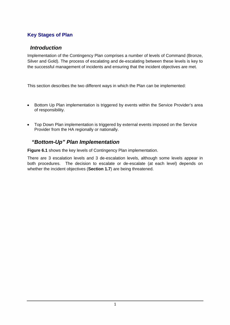
1
Key Stages of Plan
Introduction Implementation of the Contingency Plan comprises a number of levels of Command (Bronze, Silver and Gold). The process of escalating and de-escalating between these levels is key to the successful management of incidents and ensuring that the incident objectives are met.
This section describes the two different ways in which the Plan can be implemented:
Bottom Up Plan implementation is triggered by events within the Service Provider’s area of responsibility.
Top Down Plan implementation is triggered by external events imposed on the Service Provider from the HA regionally or nationally.
“Bottom-Up” Plan Implementation
Figure 6.1 shows the key levels of Contingency Plan implementation.
There are 3 escalation levels and 3 de-escalation levels, although some levels appear in both procedures. The decision to escalate or de-escalate (at each level) depends on whether the incident objectives (Section 1.7) are being threatened.
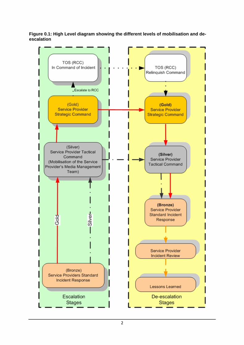
2
Figure 0.1: High Level diagram showing the different levels of mobilisation and de-escalation

3
“Bottom-Up” Plan Escalation and De-escalation
The levels of Plan implementation below refer to “Bottom-Up” Plan escalation triggered by events within the Service Provider’s Area. Depending on the level of escalation needed or how the escalation is triggered, there are four alternative sequences to implementing the Contingency Plan. In each case, the corresponding de-escalation levels are also included.
Service Provider Tactical Control (TMT) Silver Command
This shows the incident escalating to Service Provider Tactical Control as the situation deteriorates further. The Service Providers Media Management Team (MMT) will be mobilised and can alert others of the need to mobilise and keep the HA and other relevant stakeholders up to date with enhanced information from the incident scene.
Service Provider Gold Command
The sequence shows escalation to the Service Provider Gold Command. When the Service Provider decides that Strategic Command of the incident is no longer required, the Service Provider returns to Silver Command.
Highways Agency TOS (RCC) Silver Command
This sequence shows escalation up to the HA RCC Command. When the HA RCC Team relinquishes Command of the incident, the Service Provider regains Strategic Command.
“Top-Down” Plan Implementation by TOS (RCC)
The stages of Plan implementation below refer to “Top-Down” Plan escalation triggered by events outside of the Service Provider’s control. Depending on the level of escalation needed or how the escalation is triggered, there are two sequences to implementing the Contingency Plan. In each case, the corresponding de-escalation stages are also included.

4
Figure 0.2: Top down Implementation by the TOS (RCC)
Implementation of the Service Provider’s Contingency Plan may be triggered or instructed by HA, in response to events outside the Service Provider’s Area.

5
Escalation: Sequence X: TOS (RCC) Silver
This sequence shows how the TOS (RCC) implements the Area Contingency Plan and instructs the Service Provider to set up Gold Command. Contact with the Service providers will be made through the normal communication channels i.e. through the Service providers NCC. The incident will then be dealt with using their Standard Operating Procedures and the appropriate level of response will be made.
Describe how your Senior Management Team, Tactical Management Team and Media Management Team will be mobilised from a top-down plan implementation.
De-escalation: Sequence Y: TOS (RCC) stands down Gold
As the threat from the incident recedes, command is successively passed back down from the TOS (RCC), Service Provider Gold and Silver Commands and finally to Service Provider Bronze Command.

6
Blank page for repagination

1
Traffic Officer Service (TOS) Management of the Incident
Introduction
The Highways Agency TOS (RCC) will already be aware of an incident on the strategic network through liaison with the Service Provider (s) via the Regional Control Centre (RCC) and will know that the situation is either in control or is reaching a point where TOS Strategic Management is required to mitigate any further impacts on to the strategic network.
Implementation of the TOS (RCC) Command of the Incident
Bottom up escalation
A bottom up incident (Service Provider managing the incident through the command sequence Bronze, Silver, Gold), the decision to escalate the incident to TOS (RCC) command is up to the Service Provider. The reason for escalation will be that the impact of the incident cannot be mitigated within the Service Provider’s existing contract or resources.
TOS (RCC) Management of the Incident
The TOS (RCC) will manage the incident using the following HA documents:
Standard Incident Management Guidance (SIMG)
Standard Incident Management Framework (SIMF)
Regional Emergency Plans
By following the guidance in the above documents they will take Strategic command of the incident and assist the Service Provider with reducing the impact of the incident by carrying out the following:
Co-ordinate an approach towards resolution
Disseminate information to all stakeholders
Contact the Highways Agency Area Performance Manager
Make strategic decisions for the regional strategic road network
Top Down Implementation of the Service Provider Contingency Plan
A top down implementation of the Service Provider Contingency Plan could take place if the Highways Agency deems an incident or an event to be severe enough to have a major impact on the strategic road network.
The TOS via the RCC would contact the Service Provider via their NCC and inform them that their services are required. It is then up to the Service provider to determine what level of the plan that they escalate to so that they can provide the assistance that the RCC require.
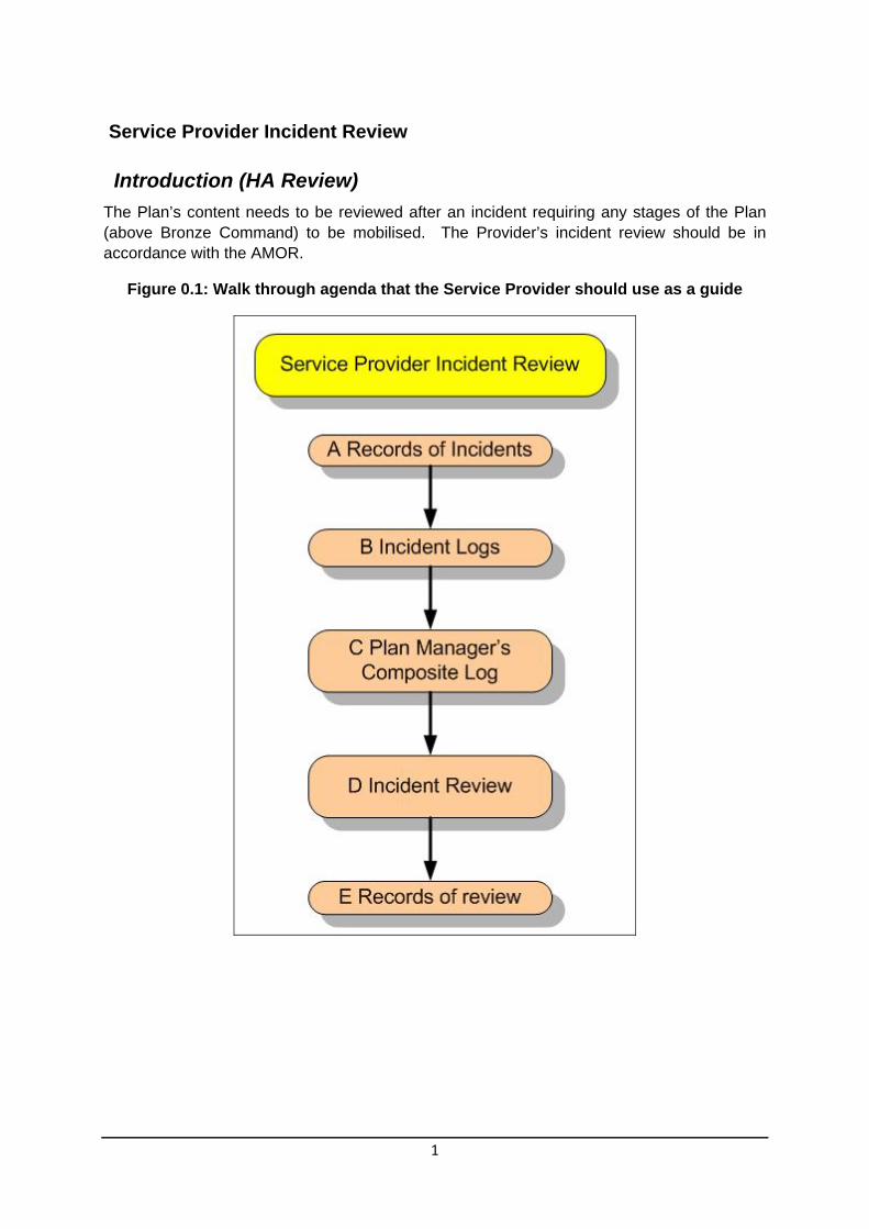
1
Service Provider Incident Review
Introduction (HA Review)
The Plan’s content needs to be reviewed after an incident requiring any stages of the Plan (above Bronze Command) to be mobilised. The Provider’s incident review should be in accordance with the AMOR.
Figure 0.1: Walk through agenda that the Service Provider should use as a guide

2
Box A – Records of Incidents
When a partial or full implementation of the Contingency Plan has occurred, records must be kept of:
Communications
Actions
Decisions
Throughout the incident, records must be kept as described in this section of the Plan. These should be recorded in the manner most convenient for each person involved (e.g. on purpose-prepared forms, in a diary or notebook, on a Dictaphone or on a computer, etc).
Records of Communications
All communications involving the relay of information and decisions made must be recorded. Records of Communication must be made by both parties involved and must include:
Date and time
Person initiating communication
Person receiving communication
Summary of information passed (including location of the incident)
Summary of response (if any)
Next actions (if any) as a result of the communication
Who will take these actions (if any)
Records to be kept for a period of xx years (according to Service Provider’s contractual arrangements)
If decision making is involved, the following additional information must be recorded:
Decision to be made
Options considered
Decision made
Reasons for decision made
Please note that it is vital to record decision making processes to permit a full review of the handling of the incident afterwards.
Records of Actions
Records of key actions must be kept to include:
Location of incident
Name of person taking action
Date and time
Action taken
Outcomes

3
Records of Decisions
Unless recorded within a Record of Communication, all key decisions must be recorded to include:
Location of incident
Name of person(s) making decision
Date and Time
Nature of decision to be made
Options considered
Decision made
Reasons for decision
Box B – Incident Logs
Incident logs are summaries of the Records above, and must be completed by:
For the purposes of the Service Provider Incident Review, list the people, teams or organisations who should prepare Incident Logs.
Each log should contain the following information:
Times and dates of specific communications, actions or decisions made
Information relayed
Actions taken
Decisions made
Box C – Plan Manager’s Composite Log
The Service Provider’s Plan Manager will then combine all logs and:
Seek clarification of inconsistencies between individual logs
Seek any missing information
Produce a composite log of the whole incident covering all actions
Box D – Internal Incident Review
The Service Provider will arrange an internal Incident Review adopting the following procedure:
The review should include:
Actions taken and assessment of their appropriateness
Actions not taken and assessment of whether they were not needed or whether they should have been taken
Communication links that were implemented and assessment of whether they worked efficiently
Communication links that were not established and assessment of whether they were not needed or whether they should have been made
The timing of actions, including establishment of communications links
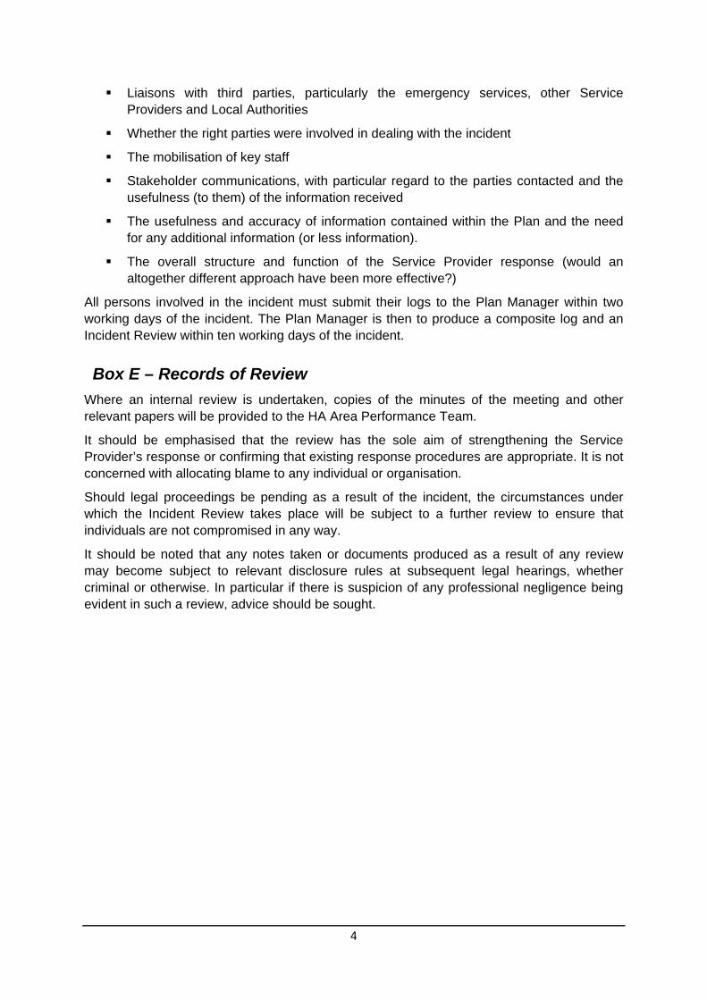
4
Liaisons with third parties, particularly the emergency services, other Service Providers and Local Authorities
Whether the right parties were involved in dealing with the incident
The mobilisation of key staff
Stakeholder communications, with particular regard to the parties contacted and the usefulness (to them) of the information received
The usefulness and accuracy of information contained within the Plan and the need for any additional information (or less information).
The overall structure and function of the Service Provider response (would an altogether different approach have been more effective?)
All persons involved in the incident must submit their logs to the Plan Manager within two working days of the incident. The Plan Manager is then to produce a composite log and an Incident Review within ten working days of the incident.
Box E – Records of Review
Where an internal review is undertaken, copies of the minutes of the meeting and other relevant papers will be provided to the HA Area Performance Team.
It should be emphasised that the review has the sole aim of strengthening the Service Provider’s response or confirming that existing response procedures are appropriate. It is not concerned with allocating blame to any individual or organisation.
Should legal proceedings be pending as a result of the incident, the circumstances under which the Incident Review takes place will be subject to a further review to ensure that individuals are not compromised in any way.
It should be noted that any notes taken or documents produced as a result of any review may become subject to relevant disclosure rules at subsequent legal hearings, whether criminal or otherwise. In particular if there is suspicion of any professional negligence being evident in such a review, advice should be sought.

1
Lessons Identified
Future Plans
Revisions of future Plans should incorporate points arising from the Incident review with the aim of ensuring a more effective response by the Service Provider when the next incident occurs.
If immediately after an incident it is the view of the Service Provider that significant improvements can be made to the HA or other operational procedures, then immediate feedback should be given to the HA Area Performance Manager, so that they can share this with other HA Areas.
Information regarding any lessons identified should be included in the Service Providers Forward Improvement Plan (FIP) and forwarded to the Network Resilience Team for inclusion in the Service Provider National FIP.
Personal Incident Debriefing
If any member of the Staff from the Service Provider requires a personal incident debrief for stress or trauma reasons, then they should contact their line manager or confidential counselling services supplied by their employers.
Include the contact details for your companies own specific counselling services here.

2
Blank page for repagination
1
Box of Reference
Introduction
The Box of Reference contains comprehensive information about the network for use during the Tactical and Strategic Management of incidents.
There are XXX Boxes:
One stored in the Tactical Management Room
One stored at the RCC(s) Specify which RCCs
The box contains a list of contents and instructions as to when these have to be checked and updated. The Service Provider Contingency Plan Manager will check and update all contents on a regular basis in accordance with the instructions.
Information in Box
There are four types of documents stored in the box of reference:
Emergency Diversion Route Document (EDRD)
Major Stakeholder Emergency Plans
Service Provider Operational Plans
Reference Information Document (RID)
Suggested Contents of the RID
Below is an example of the contents identified in the RID. This information can be inserted within the document as text or can be referenced to another location within the Service Provider’s office. This data may also be stored electronically and therefore file paths to their locations would be required within the RID.
Schematic Diagrams and Key Location Features of the Network
Emergency Crossover Points
Vulnerable Nodes
Emergency Access Points on Network
Area Depot Locations
Stakeholder Contact Details
Sign Bin Inventory
Location of CCTV Cameras
Business Continuity Plan
Network Lighting
Location of Traffic Signals
VMS Locations
Major Works on or off Network

2
External Events
Police Boundaries and contact details
Emergency Services contact details
Traffic Officer Service Boundaries
High Risk Weather Sites
Hazardous Sites Adjacent to the Strategic Network
Network Rail Bridges over the Strategic Network
Contact details for Service Provider Welfare
Plant and Equipment
Specialist Contractors to assist the Service Provider
Types of Communication Systems for liaison with all stakeholders
Liaison with Adjacent Areas

1
Plan Holders Below is an example of a heading for a list of Plan holders. The Plan holders should be individuals within such agencies that are involved in the incident or may be affected by the impact of the incident.
If further contact details are given elsewhere in another context e.g. in another Appendix or in the Box of Reference, please insert details in this table.
Further contact details in:
Copy Number
Name Organisation Position E-mail address
DVD/
Hard copy

2
Blank page for pagination

1
Contact Details Should the first person you call be unavailable, you must call the next person on the list.
Indicate here whether a duty officer rota system is in operation or whether there is a cascade system.
Tactical Decision Team (Silver Command)
Name Position Contact information
Tactical Decision Team
Person 1 Work: Fax: Mobile: Home: Email:
Person 2
Work: Fax: Mobile: Home Email:
Person 3 Work: Fax: Mobile: Home: Email:
Person etc Work: Fax: Mobile: Home: Email:
Senior Management Team (Gold Command)
Name Position Contact information

2
Senior Management Team
Person 1 Work: Fax: Mobile: Home: Email:
Person 2
Work: Fax: Mobile: Home Email:
Person 3 Work: Fax: Mobile: Home: Email:
Person etc Work: Fax: Mobile: Home: Email:
Media Management team
Name Position Contact information
Media Management Team

3
Name Position Contact information
Media Management Team
Person 1 Work: Fax: Mobile: Home: Email:
Person 2
Work: Fax: Mobile: Home Email:
Person 3 Work: Fax: Mobile: Home: Email:
Person etc Work: Fax: Mobile: Home: Email:
Administration Team
Name Position Contact information
Administration Team
4
Name Position Contact information
Administration Team
Person 1 Work: Fax: Mobile: Home: Email:
Person 2
Work: Fax: Mobile: Home Email:
Person 3 Work: Fax: Mobile: Home: Email:
Person etc Work: Fax: Mobile: Home: Email:

1
Service Provider other resources that may be required
Name Position Contact information
Other Resources
Person 1 Work: Fax: Mobile: Home: Email:
Person 2
Work: Fax: Mobile: Home Email:
Person 3 Work: Fax: Mobile: Home: Email:
Person etc Work: Fax: Mobile: Home: Email:
Service Provider Area Offices and Locations
Name Position Contact information

2
Name Position Contact information
Office 1 Work: Fax: Mobile: Home: Email:
Office 2
Work: Fax: Mobile: Home Email:
Depot 1 Work: Fax: Mobile: Home: Email:
Depot 2 etc Work: Fax: Mobile: Home: Email:
3
HA Area and Regional Contacts
Name Position Contact information
Duty Press office Work: Fax: Mobile: Home: Email:
RCC Network Operation Manager
Work: Fax: Mobile: Home Email:
Area Performance Manager Work: Fax: Mobile: Home: Email:
Work: Fax: Mobile: Home: Email:

4
Page blank for pagination

1
Definition of Major Incidents Major Incidents are any emergencies that require the implementation of special arrangements by one or more of the emergency services, the NHS or local authorities for:
The rescue and transport of a large number of casualties
The involvement either directly or indirectly of large numbers of people
The handling of a large number of enquiries likely to be generated both from the public and the news media usually to the Police
The large scale deployment of the combined resources of the emergency services.
The mobilisation and organisation of the emergency services and supporting organisations, e.g. Local Authority, to cater for the threat of death, serious injury or homelessness to a large number of people
The police or other emergency services will usually declare a major incident and notify the Highways Agency through service providers network control centres or similar.

2
Blank page for pagination

1
Definition of Critical Incidents Critical Incidents are unforeseen events that seriously impact upon the Highways Agency and its ability to deliver its ‘safe roads, reliable journeys, informed travellers’ objective. Importantly, the police, other emergency services or local authorities may not consider these types of incident as important as the Highways Agency.
Critical Incidents also include incidents of which ministers wish to be informed.
It should be noted that Critical Incidents might be, or become, major incidents.
Service Providers declare Critical Incidents for their own and the Highways Agency management purposes. If Service Providers believe that Critical Incidents are or may become major then they should notify the police immediately.
The following are deemed to be Critical Incidents:
1. Multiple collisions involving fatalities, serious injuries or vehicles disabled on a
carriageway.
2. Partial or full closure of motorways or trunk roads due to weather or road conditions.
This will also include minor incidents occurring at differing locations aggravated by
other circumstances, which taken as a whole fall into this category.
3. Collisions involving crossover of a vehicle from one carriageway to another.
4. Collisions involving passenger coaches, school minibuses, trains, or public service
vehicles resulting in fatalities or injuries.
5. Fatal collisions involving fire
6. Serious collisions involving a vehicle carrying dangerous substances (e.g. hazardous
chemicals, flammable liquids such as petrol, radioactive materials, etc)
7. Collisions on motorways or trunk roads resulting in serious/potentially serious
structural damage (e.g. to a bridge) necessitating road closures
8. Fatal collisions on motorways or trunk roads where road works are in progress

2
9. Any significant impacting partial or full closure of motorways or trunk roads due to collisions, security alerts or criminal/terrorist acts.
10. Any incident off or adjacent to the network that may meet any of the above criteria.
11. Suicide or attempted suicide resulting on the closure of lanes or carriageways.
12. Roadworks over running by 30 minutes or more, and likely to have an impact on the network.
Criteria for reporting an incident to the Minister
The Minister only needs to be informed about the most serious incidents on our network, such as the Selby train crash or the Kegworth air disaster, where there are multiple fatalities or issues of national significance.
The Ministers office also wants to be informed about the following:
Significant accidents involving a school minibus whether resulting in fatalities or not
Any serious accident involving a vehicle carrying dangerous substances e.g. chemicals, inflammable liquids such as petrol or radioactive materials
Major closure of motorways or trunk roads due to accidents, weather or road conditions and other incidents, where serious congestion is likely or has occurred
Death or serious injury of an HA employee or contractor
HA officials also need to be told about the most serious incidents. However, where there is significant damage to roadside furniture or, where there are emergency closures causing significant delays, the relevant Divisional Director should be informed only when the HA Duty Officer is unobtainable.

Glossary This is an example of a glossary but should be modified to suit the contents of the Service Provider’s own plan.
ACPO Association of Chief Police Officers
AMM Highways Agency “Area Management Memo”
APM Highways Agency Area Performance Manager
Bronze Level Command On-site incident management by Emergency Services Officer in Charge/Traffic Officer/Service Provider
Box of Reference A box that contains reference information about the network and also Operational and Major Stakeholder Emergency Plans.
Contingency Plan Response The highest level of Area response to incidents
Network Control Centre (NCC)
May be called by another name on other Areas, but is essentially a 24/7 communication service which deploys the Service Providers ISU’s
CP Service Providers Contingency Plan
Emergency Diversion Route A pre-planned route to take traffic away from an incident site
ECP Highways Agency “Emergency Contact Procedures”
EDRD Emergency Diversion Route Document
Standard Incident Response Procedures
Service Provider established plans for dealing with routine Network incidents
Gold Level Command Strategic Management of the incident
HA Area Team Highways Agency Area Performance Manager’s Team
Implementation Criteria The circumstances in which the Contingency Plan will be implemented
ISU Service Providers Incident Support Unit. These will attend the scene of an incident
MMT Service Providers Media Management Team
NILO HA National Incident Liaison Officer
NRT Highways Agency Network Resilience Team
NTCC National Traffic Control Centre
Process Flow Chart A diagram showing the procedures to be followed in the event of an incident

RCC Highways Agency Regional Control Centre (RCC)
Service Provider Managing Agent
Silver Level Command Tactical Control
Stakeholder An organisation with a vested interest in the efficient performance of the Area network, which should be informed of incidents which may affect them or their business.
Strategic Network The HA Area motorways and trunk roads
SIMF Highways Agency “Standard Incident Management Framework”
SIMG Highways Agency “Standard Incident Management Guidance”
Senior Management Team Service Providers Senior managers who will make strategic decisions for the service provider
Tactical Management Team Team of Service Provider personnel responsible for the Tactical Management of an incident
Tactical Management Room A designated room where the incident can be managed without interference from other day to day business. Should be fully functional with all equipment required to manage an incident.
TOS Highways Agency Traffic Officer Service
TRANSEC Transport Securities and Contingencies Directorate (DfT)
Guidance and Management of Service Provider Contingency Plans Version 2
Guidance and Management ofService Provider
Contingency PlansVersion 2

Blank Page for Pagination

Document Control
Revision History
Version Date Description Author
2.0 October 2010 Final Keith Blight
Reviewer List
Name Role
Document Title
Author Keith Blight
Owner
Distribution
Document Status Final

Approvals
Name Signature Title Date of Issue
Version
The original format of this document is copyright to the Highways Agency.

Blank Page for Pagination

i
List of Contents Page
Summary S-1
Chapters and Appendices
1 Introduction 1
2 Contingency Planning 1
2.1 Importance 1
2.2 Clarity 1
2.3 Links with other plans 1
2.4 Benefits of a Template 1
2.5 Nature of a Contingency Plan 2
3 Application of the Template 1
3.1 Introduction 1
3.2 Interface with Standard Incident Response Procedures 1
3.3 Existing Contingency Plans 1
4 Contents of the Template 1
4.1 Introduction 1
4.2 Template Contents (and what to do with them) 1
5 Use of Template to Produce Service Providers Contingency Plan 1
5.1 Any Difficulties or Suggestions? 1
6 Management of Service Provider Contingency Plans 1
6.1 Plan Updating 1
6.2 Scope of Updating Process 1
6.3 Plan Manager 2
7 Plan Versions and Amendments 1
7.1 Versions and Amendments 1
7.2 Version and Amendment Numbering 1
7.3 Change of Plan Notifications 2
8 Plan Updating 1
8.1 Overview 1
8.2 Routine Updating and Plan Improvements 2
8.3 Routine Updating (Flowchart Boxes A - E) 2
8.4 Improvements to the Plan (Flowchart Boxes F – K) 2
8.5 Minor Plan Changes (Included in Box E) 2

ii
8.6 Forward Improvement Plan (FIP) (Boxes M – P) 3
8.7 Contingency Planning Forum (CPF) (Box Q) 3
8.8 FIP in the CPF 4
8.9 Updating Plan content (Boxes R and E) 4
9 Plan Production Process 1
9.1 Introduction 1
9.2 Plan Media 1
9.3 HA Approval (Boxes S – T) 1
9.4 PDF Format (Box U) 1
9.5 PDF Process (Box U) 1
9.6 Print Hardcopy (Box U) 2
9.7 Plan Distribution (Box V) 2
9.8 Staff Briefings (box W) 2
10 Box of Reference 1
10.1 Introduction 1
10.2 Bound Documents 1
10.3 Reference Information Document (RID) 1 10.3.1 Checking Information in the RID 2 10.3.2 Updating the RID 4
10.4 Index to the Box of Reference 4
10.5 Audit Trail 4
11 Emergency Diversion Route Document (EDRD) 1
11.1 Introduction 1
11.2 Updating Emergency Diversion Route Document 1
11.3 EDRD Version Number 1
12 Training and Exercises 3
12.1 Introduction 3

S‐1
Executive Summary This document introduces the Highways Agency’s Template for Service Provider Network Contingency Plans.
It explains what a Contingency Plan is, why it is needed, how to prepare a Contingency Plan from the Template and to keep the plan up to date.

S‐2
Blank Page for Pagination

1
Introduction
All Service Providers (this term includes MAC and DBFO Companies) routinely deal with incidents and emergencies on the network in accordance with their own day-to-day standard incident response procedures. But what happens if these operational response procedures fail to contain the incident and the situation gets out of hand, with potentially unacceptable consequences for our customers and our reputation? “White Friday” on the M11 in January 2003 was an example of such an event, when hundreds of our customers were trapped in their vehicles overnight in freezing temperatures.
In such circumstances, management of the incident has to be escalated upwards to facilitate a more tactical or strategic response. This is the essence of the Contingency Plan. In the first instance, management of the incident can be escalated upwards within the Service Provider and a Tactical Management Team (TMT) established. This team can then make tactical decisions about the best way to manage the incident, involving third parties if necessary and ensuring that the best possible advice is given to our customers throughout. This leaves those responsible for directly dealing with the incident at an operational level free to “get on with the job” within the tactical framework established by the TMT.
If it then proves difficult to contain the effects of an incident at a Service Provider level or the effects threaten to spread across Area boundaries, the TMT can escalate management of the incident to a Strategic level, to the Highways Agency Traffic Officer Service (TOS), Regional Control Centre (RCC).
There may also be a need to introduce a Strategic Command level within the Service Provider’s own organisation if there is a need for strategic decisions within the organisation which the members of the Tactical Management Team are not empowered to make (for example, redeployment of resources into the Area or DBFO team from elsewhere in the Service Provider’s organisation).
The Contingency Plan explains how the need to escalate the management of an incident upwards is recognised, how management of the incident is undertaken at a tactical level and how it can be further escalated up to a strategic level.

2
Blank Page for Pagination

1
Contingency Planning
Importance
This is a very important plan although it will be activated only on those rare occasions when Service Providers’ standard incident response procedures prove inadequate for the circumstances. However, on such occasions, it is vital that the Plan functions efficiently and effectively. At best reputations will be at risk; at worst, lives will be at risk.
There may also be a risk of litigation. If the Plan sets out approved and tested procedures and if these have been correctly followed, this will put the Service Provider in a strong position to defend the actions taken. Without a Plan in place, there will be less certainty about how to proceed and every individual decision made at the time could be subject to scrutiny.
Clarity
The Contingency Plan will (hopefully) be seldom mobilised, but when it is, key Service Provider staff will be required to take on roles and responsibilities which are specific to the occasion. They will not necessarily need additional skills, but they will be required to apply their acquired skills in extenuating circumstances. They may have to operate in a location different to their every day job. They may need to communicate with people that they do not normally come into contact with.
The Contingency Plan should clearly explain what has to be done. It should be easy to understand and set out instructions and procedures which are easy to understand and easy to implement. All who are involved in the implementation of the Plan must gain a common understanding of its objectives and procedures.
Links with other plans
There must be consistency between Highways Agency Service Provider Network Contingency Plans and Regional Emergency Plans. Drawing on 6 years’ experience of Service Provider Contingency Plans to date, the Network Resilience Team has now drawn up a Template, to be used for all Service Provider Plans. It reflects good practice and the Highways Agency’s requirements.
Benefits of a Template

2
This Template is to be used by all Service Providers for the preparation of their Contingency Plans. This means that Plans will be readily recognisable by staff transferring from one HA Area to another. It means that the Network Resilience Team can be satisfied that all Service Providers have Plans which meet the Agency’s requirements and which will make proper provision for response escalation and incident management at tactical and strategic levels. Preparation of Plans in accordance with the Template will give reassurance to all concerned.
Nature of a Contingency Plan The Contingency Plan is designed for unforeseen circumstances. It does not prescribe specific responses to specific types of incident – those will rely on the skills of the personnel involved. The Contingency Plan is more concerned with ensuring that appropriate procedures are in place.
It is concerned with ensuring that all the right people are:
In the right place
At the right time
With the right information
To make the right decisions
That is the key to successfully managing the situation.

1
Application of the Template
Introduction
The Template defines the content of the Service Provider’s Contingency Plan and the framework within which that content should be presented. Some of the content will be Area-specific and it will be for the Plan Manager to write that in a way suited to the needs of the Service Provider. Other parts of the Plan will not be Area-specific and here the Plan Manager may use text directly from the Template.
Two points should be made:
The Contingency Plan is designed to set out procedures for escalating a response over and above that provided for in Service Providers’ day to day incident response procedures
Where such escalation plans already exist, there is no need to change them but simply to ensure that they are now captured in the standard format of the Template
Interface with Standard Incident Response Procedures
Standard Incident Response Procedures are deemed to be those that are invoked on a frequent basis, usually at a Bronze level of command. All operational staff will be thoroughly versed in these procedures and there is no need to repeat them in the Contingency Plan. However, attention should be drawn to them and the interface explained between standard procedures and Contingency Plan procedures. A key part of the Contingency Plan will explain how to establish this interface and the circumstances in which it will be done.
Existing Contingency Plans
Where the Service Provider already has robust and resilient procedures in place for escalating response to an incident, there is no intention that these should be changed. They will simply now be captured in the prescribed format of the Template so that consistency in planning can be achieved across the whole of the HA’s network. On the other hand, where consideration of the requirements of the Template indicates that established procedures could be made more robust or resilient, then preparation of a Service Provider plan from the Template will give an opportunity for improved procedures to be introduced.

2
Blank Page for Pagination

1
Contents of the Template
Introduction
The contents of the Template are explained, together with advice to Plan Managers on how to use the Template to create a specific Service Provider Contingency Plan.
Template Contents (and what to do with them)
Title Pages
The Plan Manager must:
Insert the Area and Plan details needed to replace words or numbers given by “XXX”
List of Contents
The Plan Manager must:
Update and repaginate the list of contents in the Template, including any headings, figures or flowcharts added by the Plan Manager (see below).
Executive Summary
The Plan Manager must:
Insert the details needed to replace words or numbers given by “XXX”
Add any further text considered necessary for the needs of the individual Area
Numbered Headings (Y, Y.Y, Y.Y.Y)

2
The Plan Manager must:
Use these headings unchanged. If a particular Area requires no information to be provided under the heading concerned, the heading must remain in the Plan but can be followed by the wording “This section not used.” A reason why information under this is not required should also be included.
but,
On the other hand, if necessary for clarity or comprehensiveness, the Plan Manager of the Plan may add additional headings at the second and third levels. At the second level (Y.Y), these should follow at the end of the second level headings already given in each Section (Y). Third level headings (Y.Y.Y) can be added after any second level heading.
Text
Text in bold:
The Plan Manager must:
Treat this as mandatory text which must be included in the Plan – it is usually text quoted from other documents. It will be for the Plan Manager to ensure that preceding and following text fits comfortably with the mandatory text.
Some mandatory text includes single words or numbers which are Area –specific and require to be completed by the Plan Manager. These are marked “XXX”.

3
Text in normal font:
The Plan Manager may:
Use this text for inclusion in all Area Plans. However, it is not mandatory and the Plan Manager may modify it to suit the needs of the Area or to suit personal taste in terminology.
Some recommended text includes single words or numbers which are Area –specific and require to be completed by the Plan Manager. These are again marked “XXX”.
Text in Italics (in red if printed in colour):
The Plan Manager must:
Read the explanatory text as it is not designed to be included in the plan as such. The text explains to the Plan Manager what is to be included under the heading concerned. It will be for the Plan Manager to decide precisely what information is to be presented and how it is to be presented.
Flowcharts and Figures
The Plan Manager must:
Include the figures in the Template without modification and refer to them as required. If the Plan Manager needs to add more flow charts or figures then they can.

1
Use of Template to Produce Service Providers Contingency Plan
Using the principles of response escalation and incident management set out in the Template, each Service Provider will decide how these are to be applied in practice in the Area concerned.
The Service Provider’s Contingency Plan is then produced by starting with the Template and:
Completing the Title Pages
Completing the Executive Summary
Retaining all headings
Adding any additional headings required
Retaining figures
Retaining mandatory text, but infilling any Area-specific words or numbers
Reviewing recommended text, modifying if necessary
Writing text where only an explanation of what is to be included is given
Updating the List of Contents and Appendices
It will be for the Plan author to check consistency and cross-referencing within the document, and to ensure that the final document is readily comprehensible and easy to use.
Any Difficulties or Suggestions?
If any difficulties are encountered in using the Template, advice should be sought from the:
Network Resilience Team
Highways Agency
Temple Quay House
2 The Square
Temple Quay
BS1 6HA

2
Tel: 01173-726325
E-mail: [email protected]
Any suggestions for improvements to the Template are welcome, and should also be referred to the Network Resilience Team for inclusion in the Forward Improvement Plan (FIP) and consideration by the Contingency Planning Forum (CPF).

3
Blank Page for Pagination

1
Management of Service Provider Contingency Plans The Service Provider Contingency Plan will be a comprehensive and complete document. The following sections have been prepared to guide the Plan Manager in the management of updates to their Contingency Plan and other associated documents.
Good practice and lessons learned from Service Providers have been incorporated in this document to make it as robust as possible.
This guidance is not set in stone but is considered to offer sound advice to the efficient management of Service Provider Contingency Plan. It draws attention to the many tasks that must be undertaken on a regular basis if the Plan is to remain a live and up-to-date document.
Plan Updating
Service Provider Contingency Plans have to be updated every 6 months with Plan updates to be issued on:
1st October
1st April
Change of Plan notifications (such as changes of names/contact details, etc) should be issued to Plan holders and stakeholders.
This document sets out recommended procedures for managing the updating process in such a way that the Plan is responsive to changing circumstances and remains a live and up-to-date document.
In particular, the Plan updates will take into account:
New information received and changes in legislation
New advice from the HA
Service Provider post-incident reviews (if any) and HA Cold Debriefs
Checks on existing information contained within the Plan
Organisational change within the Service Provider Team or an external party
The Plan is a complex document containing a large amount of information. Managing the updating process in such a way that the Plan remains a consistent and user-friendly document is also complex and there are many tasks to be undertaken on a regular basis. This document explains how it can be done in an efficient and effective way, drawing on experience and good practice to date.
Scope of Updating Process
The scope of the updating is set out below:
Numbering of Plan Versions and Plan Amendments
Plan Updating Process
Plan Production Process (the main document)
Updating the Box of Reference

2
Updating the Emergency Diversion Route Document
Training & Exercises
Plan Manager
The Plan Manager will be responsible for all aspects involved in the updating of the Contingency Plan and associated documents.

1
Plan Versions and Amendments
Versions and Amendments
Although the updating processes are largely the same in both cases, a distinction is made between a new Plan Version and a Plan Amendment.
A new Plan Version is:
An update of the complete main Plan, involving reissue of the complete document.
A Plan Amendment is:
An update of parts of the main Plan only, which is used when this is all that is required.
It is recommended that a new Plan Version is produced at least once a year. This ensures that all Plan holders receive a complete, up-to-date copy of the main Plan at least every 12 months. Plan Amendments can be used for the six monthly updates to advise Plan holders of the most significant changes, leaving minor changes to be aggregated in the next new Plan Version.
Please note that the other parts of the Contingency Plan – the Box of Reference and the Emergency Diversion Route Document – are subject to amendment only and do not require renewing or reissuing completely unless circumstances dictate that course of action.
Plan Amendments have been devised primarily to suit Plan holders who hold the Plan in hardcopy form. The Plan Amendment then comprises only those pages of the Plan to be amended. Plan Amendments issued in CD form will comprise both unchanged pages and amended pages.
However, if ALL Plan holders receive their plans in electronic form and no hardcopies are distributed, then the whole Plan will effectively be reissued at every update. In this case, Amendments can be dispensed with and each update treated as a new Plan Version.
Version and Amendment Numbering
Each new Plan Version should be given a sequential rising number: 1.0, 2.0, 3.0, etc.
Each Plan Amendment issued between new Plan Versions is to be given a two-part number: v.n
Where v = number of the preceding Plan Version
n = sequential Amendment number
New Plan Version 1.0 would be followed by Amendments 1.1, 1.2, etc.
Combining the previous Plan with an Amendment gives an updated Plan Version:
e.g. New Plan Version 2.0 + Amendment 2.1 = Plan Version 2.1
Plan Version 2.1 + Amendment 2.2 = Plan Version 2.2
This would be the norm but exceptions for change in legislation etc might require the plan to be updated more than once per year.
2
Note that amendments to the Box of Reference and the Emergency Diversion Route Document are to be issued at the same time as new Plan Versions or Plan Amendments, and where appropriate should bear the Plan Version number concerned. (Further details are given in Sections 5 and 6.)
Change of Plan Notifications
The general aim is to restrict Plan updates to 6 monthly intervals, accepting that there will be a slight degradation in Plan quality during the intervening period as individual items of information within the Plan become out of date. In general, it is not considered worthwhile to advise Plan Holders of every small amendment to the information in the Plan as soon as it occurs.
There is one exception and that is “Plan-critical” information, where use of out-of-date information could seriously compromise the ability of the Service Provider to mobilise or execute the Plan. Such an example might be a change in contact details of critical staff involved in the Tactical Management Team (TMT).
In such circumstances, a Change of Plan Notification should be urgently e-mailed to Service Provider Plan holders who may be directly involved in the management of an incident. The information should be sufficiently concise that the Plan Holder can simply amend his/her Plan by hand. If the amendment is more extensive (for example, several additional paragraphs), then it should be issued as a proper Plan Amendment – even if the next Plan update is not yet scheduled.
Change of Plan Notifications should be used sparingly; otherwise Plan Holders will not manage to continually annotate their plans. As with the issue of Plan updates, confirmation of receipt of Change of Plan Notifications is essential.
Any Change of Plan Notifications will be incorporated into the next new Plan Version or Plan Amendment.

1
Plan Updating
Overview
The figure below shows an overview of the Plan Updating process. It is explained in detail in subsequent sections.
Figure 8.1: Flowchart for Updating Contingency Plan

2
Routine Updating and Plan Improvements
There are two key parts to the Plan update process:
Routine checking and updating of information held within the Plan
Improvements to the Plan
Routine Updating (Flowchart Boxes A - E)
Routine Updating of the Plan involves:
Checking all factual content of the Plan
Checking text
Checking figures and flowcharts
and updating as appropriate.
Experience has shown that it is not adequate to update the contents of the Plan solely on the basis of reported changes. There must be a mechanism in place for proactively determining whether each item of information is correct. For example, in the case of Plan Holder or Tactical Management Team details, it is necessary to contact each person concerned individually and ask them to confirm that their contact details are correct or advise of any changes.
Finally, cross-references within the Plan can change as a result of an amendment elsewhere, so all cross-references should be rigorously checked before the update can be released for approval. This is most easily done by maintaining an up-to-date checklist of all cross-references in the Plan.
Improvements to the Plan (Flowchart Boxes F – K)
The Plan will be subject to change and improvement for a variety of reasons. As time progresses between updates, it is important to capture suggestions for such improvements. These will primarily emanate from:
Post-incident reviews (Box F)
Suggestions from Area staff (Box G)
Organisational change within the Service Provider (Box H) or HA (Box I)
Revisions to the Template (Box J)
Change of Plan notifications since the previous update (Boxes K and L)
These suggestions will come from a variety of sources at different times. It is necessary to have a means of capturing them (the Forward Improvement Plan document – see below) and making proper use of them (the Contingency Planning Forum – see below).
Minor Plan Changes (Included in Box E)
If a suggested Plan update does not alter a current procedure, or change the format or content of the document significantly then this change may be made directly by the Plan Manager without further formality.
Examples of this are as follows:
3
Changes to personal contact details (names and addresses)
Cosmetic changes to the document (spelling, grammar, punctuation, colours or font size, etc)
Text sent by the HA to be included in the document
However, other suggested changes should be recorded in the Forward Improvement Plan and considered by the Contingency Planning Forum, as explained below.
Forward Improvement Plan (FIP) (Boxes M – P)
The Forward Improvement Plan (FIP) is a list of suggestions for changing and improving the Plan. As new suggestions come forward, they are added to the list by the Plan Manager. Against each suggestion is recorded:
A brief description of the suggestion itself
Reasons why the suggestion has been suggested, and the benefits of making the proposed change or improvement
The originator or source of the suggestion
The section in the Plan to which it refers
The FIP also contains a section listing the Plan updates resulting from the routine checking of the Plan discussed in Section 3.3.
Contingency Planning Forum (CPF) (Box Q)
The Plan Manager has to decide which of the many suggestions in the FIP to adopt, or how to prioritise them. It is unlikely that all the suggestions received will be both suitable and sufficiently few that they can all be incorporated into the next Plan update. It is recommended that a Contingency Planning Forum (CPF) be established to assist the Plan Manager in this task and also to undertake other related functions.
The Forum should comprise key players in the Contingency Plan (both its preparation and its execution) from the Service Provider, the HA Area Performance Team and Regional Emergency Planning Manager/Officer. The functions of the Contingency Plan Forum will be to:
Monitor the quality and effectiveness of the Plan
Receive a report from the Plan Manager on Plan progress including:
o Plan updates
o Incident reviews
o Training exercises
Advise the Plan Manager on changes and improvements to be made to the next update
Generally advise the Plan Manager on any other relevant matters

4
It provides a forum within which the Plan can be regularly reviewed by those who share key responsibility for its success. It is recommended that the Forum meets once per year, shortly before each update is finalised for submission to the HA. This will enable the Forum to take stock of the latest Plan update and recommend a programme of update work for the next new Version or Amendment.
FIP in the CPF
The FIP has a key role to play in decision making by the Forum regarding the content of the next Plan update. Each of the suggestions in the FIP is considered by the Forum and classified as:
Plan Change
Plan Issue
or Discard
If a suggestion is classified by the Forum as a Plan Change, it is then incorporated into the next Plan update without further reference to the Forum. These tend to be straightforward, sensible suggestions capable of being easily incorporated into the Plan.
If a suggestion looks promising but cannot readily be incorporated into the Plan, it is classified as a Plan Issue. These could be suggestions where further consideration of the matter is required or further information needs to be collected before the suggested Plan update can be implemented. The Plan Manager will be responsible for progressing the matter and reporting back to subsequent meetings of the Forum, ideally tabling a progress report for Forum members in advance.
Finally, if the Forum considers that a suggestion should not be incorporated into the Plan, it is classified as a Discard and the originator of the suggestion advised accordingly, with the Forum’s reasons.
Further progress on Plan Changes (i.e. incorporation into the Plan) and Plan Issues is reported to the next Forum, and recorded in the FIP. The FIP therefore becomes a clear audit trail of all updates to the Plan.
Updating Plan content (Boxes R and E)
The Plan Manager will produce each plan update from the previous version of the plan to include:
Routine updates
Minor plan changes
Plan changes recommended by the CPF
Plan changes resulting from consideration of plan issues
It is the Plan Manager’s responsibility to ensure that the new Plan Version or Plan Amendment in its totality is:
Internally consistent
Easy to read
Easy to understand

5
Fit for purpose

6
Blank page for Pagination

1
Plan Production Process
Introduction
Once the updating process is complete, the Plan Production process is as follows. This section refers to the main Plan document only. Separate advice regarding the Box of Reference and the Emergency Diversion Route Document is given in Sections 10 and 11.
Plan Media
To minimise printing costs, it is recommended that as many Plan holders as possible receive their Plans in electronic form (usually DVD) or in PDF format. However, many operational staff need to have a hard copy for use when out on the network and it may be more efficient for all hard copies to be printed prior to distribution rather than each individual printing their own from an electronic version.
The Plan Production processes below allow for some copies of the Plan to be distributed electronically and some in hard copy.
HA Approval (Boxes S – T)
When the plan has been updated it will be sent to the local HA Area Performance Manager (see section 7.6.2 in the Highways Agency Network Management Manual July 2009 for clarification) for comment and approval. Any comments will be incorporated into the Plan and the FIP as required.
PDF Format (Box U)
Once the final Plan update for issue has been prepared, it should be converted into PDF format so that the version cannot be changed and that it now becomes part of an auditable trail of the evolution of the plan.
PDF Process (Box U)
The whole plan is then saved in PDF format not just the updated sections. This is now a record of the complete plan and amendments. Version 7.0, Amendment 7.1, etc. For example, Plan Version 7.1 will contain certain pages of Version 7.0 and other sections that have been amended (Amendment 7.1).
For a Plan amendment, the whole Plan is saved as PDF, but only the updated sections will be sent to hardcopy Plan holders. They will then insert the new sections in to their copy of the plan and dispose of the old ones. To do this, convert the whole plan to PDF then delete the sections that have not been updated. This file is then saved as, say, Amendment 7.1 only.

2
Print Hardcopy (Box U)
For Plan Amendments, only those sections which have been amended need to be printed and these are then distributed unbound for Plan holders to insert as amended sections in the updated Plan Version. It is recommended that whole sections of the Plan are amended rather than individual, isolated pages. While this involves more printing, it is quicker for the Plan holder to replace all pages between a pair of page dividers than selected individual ones, and it avoids any page renumbering difficulties (all pages within each section being numbered sequentially from 1 upwards).
Plan Distribution (Box V)
The hard copy Plan updates (new Versions or Amendments) will be posted to all the plan holders. Electronic versions will be e-mailed or sent by DVD to electronic Plan holders.
An Acceptance Note will be issued with all Plan updates and this has to be returned as acknowledgement that the recipient has received the update.
Given the sensitive nature of some aspects of the Plan, hardcopy Plan holders should be asked to destroy replaced pages or return them to the Plan Manager for shredding.
Staff Briefings (Box W)
Briefings should be arranged for all Service Provider Plan holders (and external Plan holders if required) to discuss the updates to the Plan and to answer any associated queries. These briefings provide an opportunity for Plan holders to reflect on the Plan and their role in it and make suggestions for Plan changes or improvements.

1
Box of Reference
Introduction
The Box of Reference contains information concerning the network that may be required by the Tactical Management Team (TMT) and Senior Management Team during an incident. The types of information stored in the box are identified in Section 13 of the Template. The information comprises:
Formal, bound documents (e.g. The Emergency Diversion Route Document, reports, operational plans and third party Emergency Plans, etc) or all could be on DVD’s or referenced to a location on the Service Providers IT network.
The Reference Information Document containing all other information and details about how to access data readily available elsewhere ( could be hard copy or on a DVD).
The contents of the Box of Reference should be updated as described below.
Bound Documents
Updating of the Emergency Diversion Route Document is dealt with in Section 11.
The other contents of the Box of Reference need to be updated as follows:
Check with the author or owner of the document whether the version held in the Box of Reference is still current
If so, retain it
If not, obtain the current version or discard the document if it is no longer valid
Not all items will necessarily need to be updated every six months. The Plan Manager should produce an updating schedule for the documents concerned. The schedule will be reviewed and updated every six months in line with Plan updates.
Reference Information Document (RID)
The Reference Information Document (RID) is a document containing information about the Service Provider’s Area network which may be required during the management of an incident. This is information that may not be available in bound documents and should be gathered and placed in a single document (DVD) for ease of use and control. This document will be used when the Contingency Plan has been mobilised and has to be updated in line with it as there are cross references between the Plan and the RID.
The RID contains information which could be useful to the Tactical Management Team but which is not otherwise readily accessible. In some cases, there may be benefit in including details in the RID about how to access the data rather than the data itself.
The RID is not distributed to Plan holders and only five copies are needed:
One held by the Plan Manager (master copy)
One held in the Service Provider’s Tactical Management Room
One held by the HA’s RCC Operations Manager(s)

2
One held by the Regional Emergency Planning Manager
One held by the HA Area Performance Manager
Given that members of the Tactical Management Team (TMT) will not necessarily be familiar with the RID before they are called upon to use it, it is considered advisable for the RID to be a clearly referenced hardcopy document and used during testing of the plan. However, if TMT prefer, and the computing facilities are guaranteed to be available, it could not be a fully referenced DVD.
Checking Information in the RID
All the information in the RID may not need updating every six months; however, it should be regularly checked to ensure its accuracy and criticality to the effectiveness of the Plan.
Below is an example of information that could be contained in the RID and the time scales associated with checking and updating this information. However, it is for each Service Provider to specify the frequency of checking appropriate for the Area concerned.
Note that where the Contingency Planning Team delegates the checking of information, that is specified. It should also be noted that unless stated otherwise, it is not sufficient to rely on reported changes. A mechanism must be in place to proactively check information and either confirm that it is still correct or be advised of any changes.

3
Table 0.1: Example Checking Schedule
Location in RID
Title To be Checked and Updated
Section 1 Introduction Every six months
Section 2 Vulnerable structures
Annually or if a major incident has rendered a structure vulnerable
Section 3 Stakeholder Contact details
Every six months
Section 4 Emergency Diversion Route
Document
Diversion routes to be updated in response to changes advised by the police, HA and LHA at
regular liaison meetings.
Section 5 Sign Bin Inventory Annually
Section 6 Emergency crossing points
Annually
Section 7 Location of CCTV Cameras
To be checked with the CCTV operators on a four monthly basis.
Section 8 Business Continuity Annually and updated at other times in response to known developments.
Section 9 Network Lighting To be checked by the Service Provider’s Lighting team annually
Section 10 Location of traffic Signals
To be checked by the Service Provider’s traffic signals team Every six months
Section 11 Location of VMS Signs
Six monthly
Section 12 Major Works and Special Events
To be checked by the Service Provider’s Road Space Team and Communications Team every six months
Section 13 Railway Bridges affecting the
network
To be checked with Network Rail every six months
Section 14 Traffic Master Access details to be checked by the Communications Team every six months
Section 15 Roadspace Diary To be checked with Roadspace Team every six months
Section 16 Highways Agency Security Notes
Updates received from the Special Traffic Team to be included when received

4
Updating the RID
The RID updating should include:
Making all amendments or corrections necessary to the information held within it
Excluding any information no longer needed
Adding any new information required
Amending the title and cover pages to show the current Plan Version
Index to the Box of Reference
All documents in the Box of Reference must be referenced and an Index of the contents of the box prepared and stored within it. The Index must be updated in line with any changes to the contents made as described above and bear the current Plan Version number.
Audit Trail
The checking and updating of information in the RID must be systematically recorded so that a clear audit trail exists.

1
Emergency Diversion Route Document (EDRD)
Introduction
Details of Emergency Diversion Routes are to be kept in a separate document called “Emergency Diversion Route Document” (EDRD) (which forms part of the Contingency Plan).
Updating Emergency Diversion Route Document
If there is a request to the Service Provider from the Local Highways Authority, the Police or the HA Traffic Officer Service asking for a diversion route to be changed, then the guidelines in Appendix 3.5 of the AMOR must be followed.
EDRD Version Number
The title and cover pages of the EDRD should be updated every six months to reflect the current Plan Version number. The main Plan and the EDRD should show the same Plan Version number at all times so that users are certain that they are using current documents.
Note that the nature of the EDRD is such that only replacement pages are supplied and that it does not require to be completely reissued at any stage.

2
Blank page for Pagination

3
Training and Exercises
Introduction
Training exercises should be carried out routinely to test the knowledge of the team members and to check that the current procedures work satisfactorily.
Exercises should be carried out at various times of the day and various days of the week, and should always be followed by a review of those involved. Many suggestions for changes or improvements to the Plan often emerge from such reviews.
The exercises may be used to test just part of the Plan (e.g. Mobilisation of the Tactical Management Team) or may involve more extensive role play.
A thorough debrief must take place after the exercise to establish learning points. These should be considered when adjusting contingency plans. A copy of these learning points must be sent to the Network Resilience Team in Bristol, such that good practice can be applied across the Network.

4
Blank page for Pagination
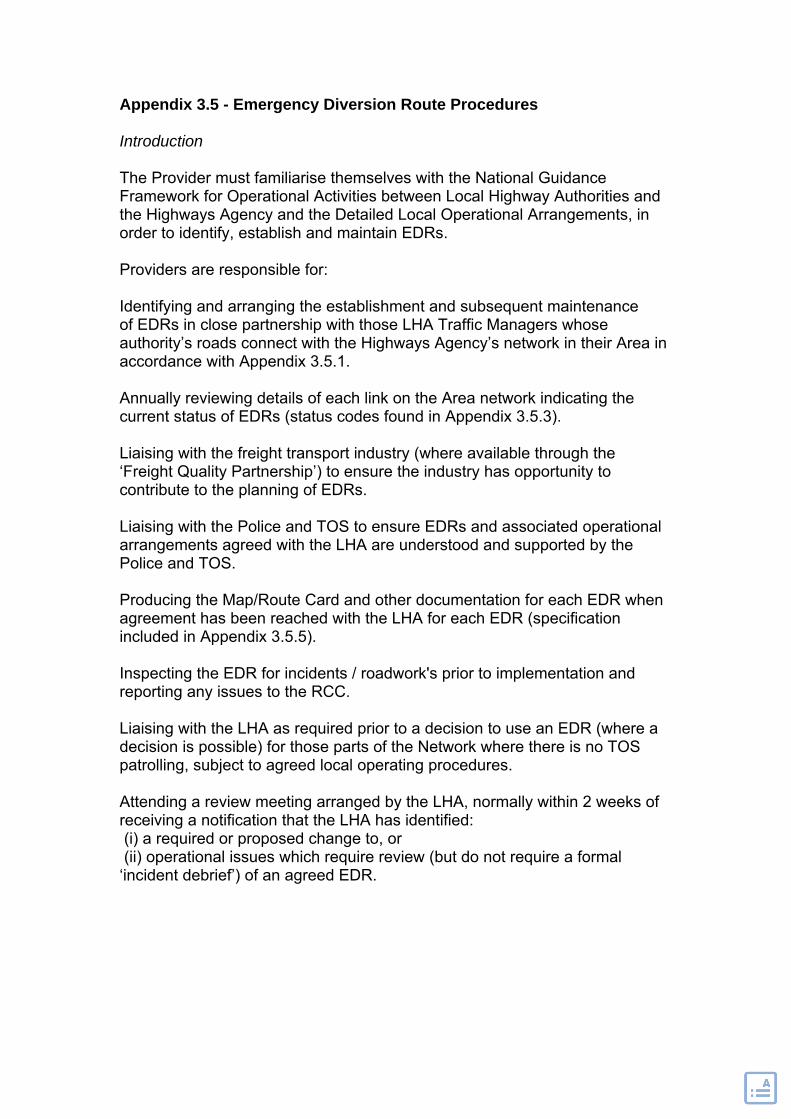
Appendix 3.5 - Emergency Diversion Route Procedures Introduction The Provider must familiarise themselves with the National Guidance Framework for Operational Activities between Local Highway Authorities and the Highways Agency and the Detailed Local Operational Arrangements, in order to identify, establish and maintain EDRs. Providers are responsible for: Identifying and arranging the establishment and subsequent maintenance of EDRs in close partnership with those LHA Traffic Managers whose authority’s roads connect with the Highways Agency’s network in their Area in accordance with Appendix 3.5.1. Annually reviewing details of each link on the Area network indicating the current status of EDRs (status codes found in Appendix 3.5.3). Liaising with the freight transport industry (where available through the ‘Freight Quality Partnership’) to ensure the industry has opportunity to contribute to the planning of EDRs. Liaising with the Police and TOS to ensure EDRs and associated operational arrangements agreed with the LHA are understood and supported by the Police and TOS. Producing the Map/Route Card and other documentation for each EDR when agreement has been reached with the LHA for each EDR (specification included in Appendix 3.5.5). Inspecting the EDR for incidents / roadwork's prior to implementation and reporting any issues to the RCC. Liaising with the LHA as required prior to a decision to use an EDR (where a decision is possible) for those parts of the Network where there is no TOS patrolling, subject to agreed local operating procedures. Attending a review meeting arranged by the LHA, normally within 2 weeks of receiving a notification that the LHA has identified: (i) a required or proposed change to, or (ii) operational issues which require review (but do not require a formal ‘incident debrief’) of an agreed EDR.

Appendix 3.5.1
Identification
In close liaison with the LHA Traffic Manager, Providers should identify EDRs for the Area network for which they are responsible in co-operation with LHAs and other stakeholders.
The identification is based on a risk assessment (a framework for EDR risk assessment is set out in Appendix 3.5.2) to assess suitability of any potential route for the emergency diversion of traffic off the Highways Agency’s network. A record of risk assessment is retained by the Provider.
Where not possible to identify a suitable EDR, a record of the assessments carried out in seeking to identify a suitable EDR will be retained by the Provider.
Where it is identified an EDR is suitable only for use by restricted classes of traffic or there is no suitable EDR available, but infrastructure improvement on the LHA network could enable one to be provided, the Agency will, subject to the agreement of the LHA, identify costs of any improvements required and provide a business case for funding (or joint funding of the work, if appropriate), so the improvement scheme can be considered within any future works programmes.
Where possible and with lack of a primary tactical route, a secondary (alternative) EDR will be identified. It is recognised that such opportunities will not generally be available.
Establishment
The Provider will agree arrangements with the LHA for establishing a necessary and appropriate signing infrastructure for each EDR on the LHA’s roads.
The LHA will undertake the sign design. Where the LHA has insufficient resources to complete the design in a timely manner, by request of the LHA, the Provider will assist with the design of EDR signing.
EDR signing will be designed to incorporate local circumstances, and will:
(i) Include sufficient repeater signs to ensure confidence is maintained for diverted road users throughout their journey and
(ii) be ‘closed out’ between the start of the EDR and subsequent return to the Agency’s network.

Sign installation should be undertaken by the LHA or in co-operation with the Provider.
Secondary EDRs will not be permanently signed unless the LHA and the Agency agree exceptional circumstances make this advisable. However, documentation referred to in Appendix 3.5.5 is required for EDRs.
Maintenance
The LHA will undertake routine inspections of EDR signing on its roads in accordance with the LHA’s normal cyclic maintenance regime for safety and service inspections. A copy of their inspection report should be forwarded to the Provider within 28 days of the inspection being carried out.
The LHA will rectify any defects of EDR signs in accordance with their performance standards for rectification of defects which represent an imminent danger to road users.
The Provider is to carry out an annual inspection of each EDR and associated signing in its Area.
The Provider is to ensure the Service Manager is advised of any actions required as a result of inspections or reviews and to take such actions necessary to ensure a robust network of EDRs continues to be available.
Appendix 3.5.2 Framework for EDR Risk Assessment The Provider must conduct an EDR risk assessment. As with any design or management decision, the person responsible for undertaking the risk assessment must be appropriately skilled and experienced to properly undertake the task, whilst taking into account the particular and unique circumstances of the potential EDR being considered.

TACTICAL DIVERSION ROUTES - RISK ASSESSMENT GUIDANCE Agency network Route: ………………
…. Agency network Road location requiring diversion:
……………….
Proposed diversion on LHA road
………………….
Identified Risks Risks arising from diversion of traffic onto the proposed diversion route
All classes of road users
Increased traffic volumes
Change in the traffic composition on the diversion route, particularly with regard to increased proportion of HGVs
Other risks?
Other risks?
Other risks?
Risk Assessment
Identified Risks Risks arising from particular features on the proposed diversion route
Schools Hospitals Sports venues
Level crossings
Other risks?
Other risks?
Risk Assessment

TACTICAL DIVERSION ROUTES - RISK ASSESSMENT GUIDANCE Risks arising from suitability of route for reducing incident-related congestion
Ability of proposed route to accommodate anticipated volumes of HGVs
Height restrictions
Weight restrictions
HGVs unable to negotiate diversion route due to alignment - e.g. by low-loaders grounding, car-transporters, cranes etc damaging adjacent/ overhanging buildings
Sports venues, special events venues etc
Traffic management and control systems operating on proposed diversion route
Risk Assessment
Risk Mitigation Establish different diversion routes for each direction of travel
Hold all HGVs on the network
Hold all AILs, transporters, large cranes, selected AILs,
Arrangements for LHA to manage diverted traffic
Avoidance of critical times, e.g. when activities at
Other mitigation?

etc on the network
on their network by changing normal traffic management and control
venues, special events etc affect the proposed diversion route are taking place
Risk Assessment
Infrastructure improvements (where justified) Alignment Remove
weight limits Other improvements?
Other improvements?
Other improvements?
Other improvements?
Risk Assessment

Appendix 3.5.3 EDRs are classified as follows:
Class 1
A route agreed as a suitable EDR under the arrangements set out in this procedure by co-operation of LHA, TOS and the Police and is permanently signed.
Class II
A route is accepted by all parties as a possible EDR, but is not signed, and may not be formally accepted by the LHA.
Class IIIa
A route is identified as a potential EDR but is acknowledged to be inadequate at certain times for diversion of traffic off the Agency’s network and there is no alternative superior EDR option.
Class IIIb
A route is identified as a potential EDR but is acknowledged to be inadequate for diversion of traffic off the Agency’s network due to physical constraints and there is no alternative superior EDR option.
Appendix 3.5.4
Documentation for EDRs
Operational and Infrastructure Records and the EDR File
The Maps/Route Cards, as described in F1 in Appendix 3.5.5, for the agreed EDRs will be held as the ‘EDRs File’.
Documentation records for each EDR are needed to meet the following requirements:
(i) a map-based record showing the EDR;
(ii) operational information and
(iii) a record of signing and other infrastructure for the route.

Appendix 3.5.5
Document Format and Requirements
F1 Map/Route Cards
Shall show the essential details of the relevant Agency network road, the relevant link closure to which the EDR applies and the EDR on the LHA network using an OS map base.
F2 Operational information, F3 – Sign and Infrastructure information and F4 – Additional information
Shall be in a format agreed by the partners agreeing and operating the route.
Each record document shall include:
(i) EDR description;
(ii) EDR Identification*;
(iii) the date of issue,
(iv) the names of the stakeholders agreeing the route and
(v) subject to their agreement, the logo of each stakeholder.*
Route identification number to be of the format:
Road number / Route Direction followed by its route direction (BD- Bi-Directional, S- Southbound, N- Northbound, E- Eastbound and W- Westbound)/Agency Area number (1-24) / Diversion number (to be a unique number for the Area, using a suitable system agreed with the SDT). A diversion route will be assigned a number similar to ‘A1-BD-14-11’
The information requirements of the documentation are as set out in F1 to F4 below.
F1 Map/Route Card
� The part of the Agency’s network which is closed;
� the EDR;
� the road numbers of all relevant Agency network roads and the EDR;
� directional indication as necessary and

� boundaries (if any) between:
(i) LHAs
(ii) Agency Area operational boundaries;
(iii) TOS operational boundaries (if applicable) and
(iv) Police service operational boundaries.
F2 Operational Information
� Sufficient detail of junctions both at the Agency network/LHA road junction and at junctions on the EDR to illustrate an exact route to be followed by diverted traffic;
� local names of junctions and any other significant ‘landmark’ features on the Agency network;
� major traffic generators on the EDR, or likely to affect/be affected by its use;
� for dual carriageways on the Agency network, whether the emergency diversion applies to closures of both carriageways or only to one direction;
� whether the EDR is for use with two-directional traffic (i.e. can be used for diverted traffic in both directions whether both carriageways of the Agency network road link are closed, or not);
� whether the EDR is suitable for all types of vehicle or not;
� special arrangements for emergency diversion or retaining HGVs and any other vehicle class, if applicable;
� if the EDR cannot be used by diverted traffic in both directions, the directional EDR information to be used in the event of a closure of both carriageways. Implementation procedures for the tactical diversion route, including responsibilities for each action;
� potential traffic problems that may be encountered with use of the EDR (e.g. peak-time congestion, regular public events such as sports matches, etc);
� requirements for times when use of the EDR may be of limited effect (e.g. at peak times) and/or
� special arrangements e.g. for controlling rate of egress from the Agency network road at peak times, 12
� special operating arrangements for the EDR (e.g. requirements for adjustment to the phasing of traffic signals on the LHA network or for traffic

signals under the Agency’s control at the junction of the Agency and LHA networks, change of signed priority at junctions etc);
� operating arrangements including responsibility for ensuring that traffic diverted onto a EDR does not run on untreated surfaces in winter conditions;
� responsibilities for changing variable/flap signs and for placing temporary signs and their removal on closedown and
� any requirements for complementary plans for setting VMS for the LHA’s (local) and the Agency’s (strategic) VMS signs (arrangements should be made through the Agency’s (NTCC) regional liaison officer (via the Service Manager) for discussions with NTCC to agree the complementary VMS plans with the LHA).
Contact information
Telephone contact details to be shown for:
� LHA office hours contact,
� LHA out-of-office hours contact
� TOS contact;
� Provider NCC,
� Police Control Room;
� significant traffic generators on, or likely to affect/be affected by use of the tactical diversion route.
F3 Sign and Infrastructure Information
� The symbol sign in use applicable to the tactical diversion route;
� the location and information provided on any flap/variable signs;
� the storage location and inventory for temporary signage;
� the locations in which any temporary signage is to be placed;
� the location of any traffic control equipment on the EDR (e.g. traffic signals);
� the location of any Agency VMS immediately adjacent to the affected Agency network road link.
� the location of any LHA VMS on or relevant to the EDR;
F4 Additional Information
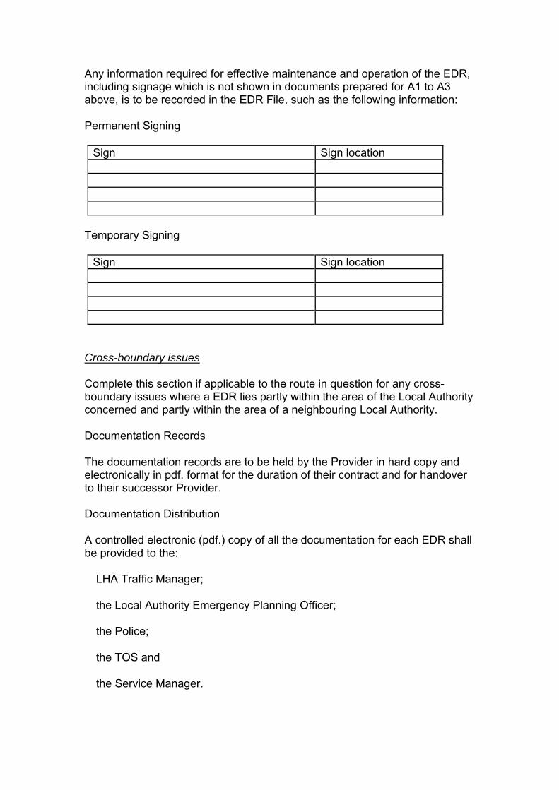
Any information required for effective maintenance and operation of the EDR, including signage which is not shown in documents prepared for A1 to A3 above, is to be recorded in the EDR File, such as the following information:
Permanent Signing
Sign Sign location
Temporary Signing
Sign Sign location
Cross-boundary issues
Complete this section if applicable to the route in question for any cross-boundary issues where a EDR lies partly within the area of the Local Authority concerned and partly within the area of a neighbouring Local Authority.
Documentation Records
The documentation records are to be held by the Provider in hard copy and electronically in pdf. format for the duration of their contract and for handover to their successor Provider.
Documentation Distribution
A controlled electronic (pdf.) copy of all the documentation for each EDR shall be provided to the:
� LHA Traffic Manager;
� the Local Authority Emergency Planning Officer;
� the Police;
� the TOS and
� the Service Manager.

The record of agreement shall include those cases where it is acknowledged that no suitable EDR can be identified
One collated set of laminated Map/Route Cards for each EDR shall each be provided LHA and the Police and the TOS and new Map/Route Cards are to be issued as they are agreed.
Providers shall determine their own requirements for distribution of documentation within their own organisations.

Asset Maintenance and Operational Requirements
Area 10 • AMOR Version 1.7
July 2011
Appendix 4
Severe WeatherOperational Requirement
Version 1.2
Issue: [1] Revision: [0] Date: [00/00/00] Page i
[SERVICE PROVIDER]
[AREA OF RESPONSIBILITY]
SEVERE WEATHER PLAN

Issue: [1] Revision: [0] Date: [00/00/00] Page ii
DOCUMENT CONTROL AND DISTRIBUTION
Document Owner (responsible for maintenance, upkeep and amendment)
[Name/Title]
Document Issue and Revision Record
Issue Revision Date Issue/Revision Description Approved
Document Distribution List
Copy Number Name Organisation
The distribution list should include: relevant Service Provider staff, and sub-contractor staff, Highways Agency staff, police authorities, adjacent local highway authorities, adjacent Highways Agency Service Providers (including DBFO companies) and any other key stakeholders such as weather forecast providers. The internal document distribution should include all decision makers and managers.
The above document control and document distribution tables should be amended to comply with individual organisations’ own quality management procedures.
Documents should preferably be distributed electronically and, to preserve format and maintain document control and security, PDF format is recommended.

Issue: [1] Revision: [0] Date: [00/00/00] Page iii
CONTENTS
DOCUMENT CONTROL AND DISTRIBUTION................................................................................ii 1 INTRODUCTION........................................................................................................... 1-1 1.1 Statement of service ..................................................................................................... 1-1 1.1.1 Risk periods .................................................................................................................. 1-1 1.1.2 Service timetable........................................................................................................... 1-2 1.2 Contractual arrangements............................................................................................. 1-3 1.2.1 Liability .......................................................................................................................... 1-3 1.3 Area Network ................................................................................................................ 1-3 1.3.1 Description of Area Network ......................................................................................... 1-3 1.3.2 Extent of Area Network ................................................................................................. 1-3 1.3.3 Area Network Features ................................................................................................. 1-4 1.3.4 Local problem areas...................................................................................................... 1-4 2 GENERAL PLANNING................................................................................................. 2-1 2.1 Operational planning ..................................................................................................... 2-1 2.1.1 General arrangements .................................................................................................. 2-1 2.1.2 Liaison and arrangements............................................................................................. 2-2 2.1.3 Escalation arrangements .............................................................................................. 2-4 2.1.4 Health and Safety.......................................................................................................... 2-5 2.2 Reporting ...................................................................................................................... 2-5 2.2.1 Winter Reporting ........................................................................................................... 2-5 2.2.2 Severe Weather reporting ............................................................................................. 2-6 2.2.3 Additional reporting ....................................................................................................... 2-6 2.3 Records......................................................................................................................... 2-6 2.4 Review .......................................................................................................................... 2-7 2.5 Weather information...................................................................................................... 2-7 2.5.1 National Domain Network of Environmental Sensor Stations ....................................... 2-8 3 RESOURCES ............................................................................................................... 3-1 3.1 Human resources.......................................................................................................... 3-1 3.1.1 Key personnel ............................................................................................................... 3-1 3.1.2 Staffing levels................................................................................................................ 3-1 3.2 Compounds and facilities .............................................................................................. 3-2 3.2.1 Compounds................................................................................................................... 3-2 3.2.2 Fuel ............................................................................................................................... 3-2 3.3 Treatment materials ...................................................................................................... 3-2 3.3.1 Material storage and brine production........................................................................... 3-3 3.3.2 Supply arrangements .................................................................................................... 3-3 3.3.3 Reserve / contingency arrangements............................................................................ 3-3 3.4 Vehicles and plant......................................................................................................... 3-3 3.4.1 Operational Reserve Winter Service Vehicle and contingency arrangements .............. 3-4 3.4.2 Vehicle maintenance arrangements.............................................................................. 3-4 3.4.3 Arrangements with supply chain partners ..................................................................... 3-5 4 WINTER SERVICE ROUTE PLANNING ...................................................................... 4-1 4.1 Winter Service Route design......................................................................................... 4-1 4.1.1 Precautionary treatment routes..................................................................................... 4-2 4.1.2 Reactive treatment routes ............................................................................................. 4-2 4.2 Winter Service Route summary .................................................................................... 4-2 5 ACTIONS FOR WEATHER CONDITIONS................................................................... 5-1 5.1 Winter decision and treatment matrices ........................................................................ 5-1 5.1.1 Decision Matrix ............................................................................................................. 5-2 5.1.2 Treatment Matrix Guide ................................................................................................ 5-3 5.1.3 Footway and cycle track treatment snow clearance...................................................... 5-4 5.2 Treatment/Actions......................................................................................................... 5-4 5.2.1 Precautionary treatment................................................................................................ 5-4 5.2.2 Reactionary treatment for snow and ice........................................................................ 5-5 5.2.3 Freezing rain ................................................................................................................. 5-7

Issue: [1] Revision: [0] Date: [00/00/00] Page iv
5.2.4 High winds (including Severe Gales and Storms) ......................................................... 5-7 5.2.5 Heavy rain..................................................................................................................... 5-8 5.2.6 Fog................................................................................................................................ 5-8 5.2.7 High temperatures......................................................................................................... 5-8 APPENDICES & SCHEDULES ................................................................................................... - 0 - A.1 Definitions and Abbreviations ................................................................................A.1-1 A.2 Audit Checklist .........................................................................................................A.2-1 A.3 Area Map...................................................................................................................A.3-1 A.4 Interface Drawings...................................................................................................A.4-1 A.5 Network Features .....................................................................................................A.5-1 A.6 Decision Maker Duty Rota.......................................................................................A.6-1 A.7 Internal Contact List ................................................................................................A.7-1 A.8 External Contact List ...............................................................................................A.8-1 A.9 Mutual Aid Agreements ...........................................................................................A.9-1 A.10 Severe Weather Desk Duty Rota...........................................................................A.10-1 A.11 Risk Assessments .................................................................................................A.11-1 A.12 Back up Reporting Forms .....................................................................................A.12-1 A.13 Operatives Schedule..............................................................................................A.13-1 A.14 Training Records....................................................................................................A.14-1 A.15 Compounds, Depots and Facilities Schedule .....................................................A.15-1 A.16 Fuel, Pump Maintenance and contingency arrangements .................................A.16-1 A.17 Vehicles and Plant Schedule ................................................................................A.17-1 A.18 Winter Service Route Schedules and Drawings..................................................A.18-1 A.19 Solid Vertical Barrier Schedule and Clearance Plan...........................................A.19-1 B.1 Severe Weather Desk Exercises and Briefings .....................................................B.1-1 B.2 Weather Information ................................................................................................B.2-1 B.3 Anti-icing/De-icing Materials...................................................................................B.3-1 B.4 Deployment of Reserve Winter Service Vehicles..................................................B.4-1 B.5 Special Considerations ...........................................................................................B.5-1 B.6 Treatment Options/Techniques ..............................................................................B.6-1
Notes for compiler:
This document is a template against which individual Service Providers must base their own individual Severe Weather Plans.
Instructions are shown in italics e.g. Service Provider to include details of …..
Square brackets denote a requirement for area/route specific text e.g. Details of the [Area No / Route DBFO] Network are…..
All of the text in red should be removed, completed, replaced or amended to suit local circumstances as appropriate.
Tables should be completed as appropriate or replaced with the Service Provider’s own tables. Where the Service Provider’s own tables are used they should include, as a minimum, the information detailed within the prescribed tables.
As the Severe Weather Plans will be public documents it is recommended that, to ensure consistency between documents, the basic style and formatting of the template should not be altered.
Issue: [1] Revision: [0] Date: [00/00/00] Page 1-1
1 INTRODUCTION Severe Weather refers to any meteorological phenomena with the potential to endanger safe passage or cause disruption on the Area Network, and includes snow, ice, heavy rain, high winds, fog and high temperatures. As such year round planning is required to manage Severe Weather events in an appropriate manner.
Severe Weather Service comprises the operational and alert procedures, and actions necessary to ensure safe passage on the Area Network is not endangered by Severe Weather, as far as is reasonably practicable. Winter Service is the element of Severe Weather Service which focuses on the routine precautionary and reactive treatments required to keep lanes on the Area Network free of ice and snow.
This section of the Severe Weather Plan outlines the scope of the services provided, responsibilities for provision of those services and details the extent of the Area Network on which the service is provided. The definitions and abbreviations are provided in Appendix A.1.
This Severe Weather Plan for [Area No / Route DBFO] describes the procedures and operational arrangements for the delivery of an effective Winter Service, to ensure safe passage for customers using the highway, and details the alert procedures and actions in the event of other Severe Weather. It is a mandatory requirement for the Service Provider to demonstrate their preparedness by developing this Severe Weather Plan. Instruction and contextual guidance to help the Service Provider compile the Severe Weather Plan is appended.
[Service Provider] will ensure the operational activities contained in this plan dovetail with other Highways Agency’s Severe Weather Plans (e.g. Traffic Officer’s Severe Weather Plan).
The document serves a number of specific purposes:
Contract Document - The Severe Weather Plan outlines contractual responsibilities of the Highways Agency and their Service Provider.
Quality Plan - The Severe Weather Plan forms part of Service Provider’s quality or business management system.
Contingency Plan - The Severe Weather Plan is linked with the Highways Agency’s wider contingency arrangements.
Operations Manual - The Severe Weather Plan describes the processes, procedures and operational arrangements for those responsible for delivering Winter Services and details the alert procedures and actions in the event of Severe Weather.
Reference Document - The Severe Weather Plan is a comprehensive reference document.
1.1 Statement of service [Service Provider] will endeavour to fulfil the Highways Agency’s Severe Weather Requirement [within Area No / on the Route DBFO] in an efficient and safe manner.
1.1.1 Risk periods The year round weather service provided through HAWIS facilitates improved planning and warning for Severe Weather events. Certain weather types can be expected during particular risk periods, these are shown below for guidance. This does not absolve the Service Provider of the obligation to provide an appropriate service at any other time of the year if the need arises.
Weather Type Risk Periods (months inclusive) Snow, Ice and Freezing rain October through to April Heavy rain January through to December High winds (including Severe Gales and Storms) September through to June Fog October through to January High temperatures June through to August

Issue: [1] Revision: [0] Date: [00/00/00] Page 1-2
1.1.2 Service timetable Key dates for the provision of reports and preparedness are summarised in the following table. Service Provider to include any other relevant dates in the table.
A checklist is provided in Appendix A.2.
Date Who Action
Initially no later than 4 weeks before possession date Subsequent years by 21 August
Service Provider Submit Severe Weather Plan hold point
18 September HA Service Manager HA National Winter & Severe Weather Team
Check and approve Severe Weather Plan
Pre Operational Winter Period and Mid Operational Winter Period
Service Provider Effectiveness of Sensors Inspection Report
30 September Operational Summer Period concludes
1 October Operational Winter Period commences
Monthly from 1 October Service Provider Complete and submit Salt Capability Spreadsheet
Monthly from 15 October Service Provider Complete and submit Non warranty defect report spreadsheet
No later than end of October Service Provider Completion of Severe Weather Desk exercises and briefings
by 18 December Service Provider Feedback and action planning from exercises and briefings
Mid Operational Winter Period and Post Operational Winter Period
Service Provider Review and update the Winter Service and Severe Weather infrastructure inventory database
31 March Service Provider Finalise list of key issues to feed into winter lessons learnt
30 April Operational Winter Period concludes
1 May Operational Summer Period commences
May Service Provider Winter & Severe Weather review
31 May Service Provider Submit Salt Restocking Plan
30 June HA Service Manager HA National Winter & Severe Weather Team
Check and approve Salt Restocking Plan hold point
June Service Provider Winter & Severe Weather report to HA (Operational Assessment Report)

Issue: [1] Revision: [0] Date: [00/00/00] Page 1-3
1.2 Contractual arrangements Winter Service duties including precautionary treatment, reactive treatment and snow clearance are the responsibility of [Service Provider].
Severe Weather duties including operational considerations, alert procedures and actions are the responsibility of [Service Provider].
The Service Manager must be closely involved in any planning activities. The Joint Operating Principles states that the Traffic Officer Service must have no input into the decision making process other than providing information on Area Network issues, including recovery of abandoned vehicles to the Service Provider via the Regional Control Centre (RCC) and National Traffic Control Centre (NTCC).
1.2.1 Liability Where arrangements are made with other service providers or Highway Authorities for Winter Service provision and Severe Weather actions to be provided by them on the Area Network, it is the responsibility of [Service Provider] to ensure such service has been carried out. Arrangements made do not absolve the Service Provider’s obligations.
1.3 Area Network
1.3.1 Description of Area Network The Service Provider to include a description of their Area Network including general details or features that may impact on Winter Service operations and areas most likely to be affected by Severe Weather.
1.3.2 Extent of Area Network The extent of Area Network covered by this plan is shown in the following table and also detailed in the Area Map at Appendix A.3. The key interfaces are defined in the interface drawings which are included within Appendix A.4.
Service Provider to include details of Area Network
Extent of Area Network
Road Extent Length (km)
[A999] From [x] to [y]
Service Provider to include details of sections of 3 lane or more carriageway. Where none exist a positive statement to that effect should be included here.
Sections of three lane or more carriageway
Road Extent Number of lanes
[A999] From [x] to [y]

Issue: [1] Revision: [0] Date: [00/00/00] Page 1-4
Service Provider to include details of footway and cycle track routes to be treated. Where none exist a positive statement to that effect should be included here.
Footway and cycle track routes
Category From To Route Description Map ID
[1a]
Where routes adjoin Local Highway Authority footways their categorisation should be adopted, otherwise routes should be categorised appropriately in accordance with the ‘Well Maintained Highways – Code of Practice for Highway Maintenance Management’. There is no need to detail those at category 4 as this will simply be the remainder of the network. Maps should be included at Appendix A.3 and appropriate cross references included in the above table.
1.3.3 Area Network Features [Service Provider] has identified the following network features that require special consideration with regard to weather within the Area Network, and features that occur at boundary interfaces. Details of each Network Feature are contained in Appendix A.5.
The Service Provider to identify features and record details in Appendix A.5.
1.3.4 Local problem areas There are a number of known problem areas including trouble spots requiring special consideration and mitigation measures within the Area Network.
parts of the network at high altitude;
areas prone to low temperature/low humidity conditions where special measures may be required;
sections of road of a gradient that may result in problems in certain conditions e.g. jack knifed lorries;
areas commonly prone to climatic conditions such as strong cross winds that would result in snow drifting and overturned vehicles;
any structures where differential treatments or special measures may be required;
low temperature low humidity problem spots require mapping as these may require additional treatments;
areas where, from experience, particular problems arise where the service provision can be hampered, including traffic calming areas.
The following table shows the location, problem, special considerations and mitigation measures identified in respect of the problem areas.
Location Problem Special Considerations and Mitigation Measures
[A999]

Issue: [1] Revision: [0] Date: [00/00/00] Page 2-1
2 GENERAL PLANNING
2.1 Operational planning This section of the Severe Weather Plan contains [Service Provider's] general operational procedures for delivery of Winter Service and details the alert procedures and actions in the event of Severe Weather on the [Area No/Route DBFO] network and includes arrangements for liaison and co-operation with key stakeholders to promote delivery of a consistent and co-ordinated service.
Service Provider to include area specific introduction as appropriate.
Operational procedures detailed in this Severe Weather Plan will be tested through a Severe Weather Desk exercise. [Service Provider] will plan and execute a Severe Weather Desk exercise prior to the Operational Winter Period to test the delivery and resilience of the Severe Weather Plan and identify areas for improvement. Planning for the exercise must be in consultation with the Service Manager, Emergency Planning Managers and the National Winter & Severe Weather Team to ensure critical and vulnerable points in the service are tested (Appendix B.1).
[Service Provider] will hold Severe Weather briefing sessions prior to the Operational Winter Period to ensure the relevant stakeholders are fully briefed. Feedback and actions will be reported to the National Winter and Severe Weather Team as per the service timetable (Section 1.1.2). An example attendance register and summary of actions template are contained in Appendix B.1.
2.1.1 General arrangements
2.1.1.1 Process Service Provider to include a detailed description of the process including forecast, decision, instruction, treatment, monitoring loop and command and control arrangements for both Winter Service and Severe Weather events. (Use of a flowchart process diagram is considered best practice).
2.1.1.2 Decision Maker Service Provider to include details of the decision maker(s) e.g. Duty Officer and definition of the role(s).
The key personnel responsible for delivery of the services defined within this document are detailed in Section 3.1.1.
2.1.1.3 Duty Rota Service Provider to include duty rotas for all personnel involved in Winter Service and Severe Weather operations.
The Decision Maker Duty Rota is included at Appendix A.6.
2.1.1.4 Salt management [Service Provider] will develop and submit a Salt Restocking Plan (Service Timetable Section 1.1.2), providing evidence for supply arrangements.
[Service Provider] will submit a Salt Capability Spreadsheet (Service Timetable Section 1.1.2) to indicate [Service Provider’s] stock holding capability and Reporting Threshold profile (with supporting evidence) in line with the Minimum Contractual Salt Stock Levels (Appendix B.3).
Service Provider to define Reporting Threshold profiles for salt stocks (and stocks of other appropriate material) taking into consideration local circumstances and other known risks to stock supplies. The reporting threshold will be the threshold for the automatic ordering of additional stock. Attention is drawn to Minimum Contractual Salt Stock Levels.

Issue: [1] Revision: [0] Date: [00/00/00] Page 2-2
[Service Provider] will review the defined threshold profile on a monthly basis and, if necessary, adjust it to account for changing circumstances during the Operational Winter Period.
2.1.2 Liaison and arrangements The management of the Area Network and the interface with other networks is essential to the consistent provision of Winter Service and actions in the event of Severe Weather. Liaison with Traffic Management Directorate (TMD) is also important to provide up to date customer-facing functions such as traffic information, active management of traffic flows and incident response.
2.1.2.1 Internal communication arrangements [Service Provider] will provide and maintain an effective telecommunications system between the Service Manager, the Service Provider’s supervisory staff and operational vehicles. Mobile telephone communication must not be relied upon since these can become over loaded particularly during extreme conditions, or in the event of an incident causing major congestion.
When considering the provision of a dedicated telephone number, the Service Provider should consider combining this with other requirements such as those in connection with incident management. Substantial operational benefits can be obtained by providing a permanently manned control centre to co-ordinate the Service Provider’s work.
The communication system for all Winter Service Vehicles and the back-up communication system for all Winter Service Vehicles include.
Internal communication is by [radio/cellular telephone].
The arrangements for backup communications are [details].
Service Provider to give details of internal communication arrangements including contingency arrangements.
A comprehensive internal contact list can be found in Appendix A.7.
2.1.2.2 External communication arrangements The Service Provider must discuss with appropriate stakeholders including adjacent authorities and private network managers (including motorway service areas, airport / rail roads) to agree management arrangements. As part of these discussions the Service Provider must highlight parts of other networks that are important to its operational effectiveness and that of the Highways Agency.
[Service Provider] has established clear lines of communication and agreed contact names and numbers to ensure communication is possible at all times.
The following table indicates the contacts of stakeholders who are important to [Service Provider’s] operational effectiveness.
Road Location Contact
[A999] [e.g. junction / exit] [stakeholder]
A comprehensive external contact list can be found in Appendix A.8.

Issue: [1] Revision: [0] Date: [00/00/00] Page 2-3
2.1.2.3 Liaison with major highway schemes Service Provider to include advanced notification of any major schemes within the Area Network and contacts for any such schemes in the table below to maintain continuity with all winter treatments and any Severe Weather procedures and actions.
Road Location (e.g. junction to junction) Type of scheme Contact
[A999]
2.1.2.4 Mutual aid agreements Mutual aid is where one service provider may have a resource issue, a second or third (etc) service provider will assist in delivering the same goal. Mutual aid can be, from the sharing of resources such as salt, the sharing of facilities that may provide improved resilience of the Area Network, or the provision of a full Winter Service to a particular part of another network. For example, there are local roads that Service Providers may treat to ensure their own operational effectiveness such as access routes to depots.
It can also be used to provide support to, or obtain support from, other network operators during times of stress, such as during Severe Weather, to the benefit of the road users. The provision of support at such times and capabilities of provision should be discussed and contact details agreed.
Service Provider to include a statement explaining what mutual aid arrangements are in place, including contact details.
[Service Provider] will document all requests for support from, or to, other operators and the subsequent decisions, with reasons, by completing the Mutual Aid Agreement forms. Completed forms can be found in Appendix A.9 (an electronic version of the template is available from the Service Manager).
[Service Provider] will submit signed copies of completed forms to the Service Manager with additional copies issued to the provider/recipient of mutual aid. It is noted that mutual aid arrangements do not absolve [Service Provider’s] obligations.
2.1.2.5 Cross boundary agreements [Service Provider] will ensure the cross boundary agreements are in place at the interface of the Area Network and adjacent networks to ensure a consistent service that will not leave potentially important sections of either network untreated.
Service Provider to include a statement explaining what cross boundary agreements are in place with adjacent Highway Authorities and Service Providers to maintain continuity with all winter treatments and any Severe Weather procedures and actions.
Agreements to include road, location (extent) and timing (particularly relevant when considering access to depots) of service.
2.1.2.6 Abandoned vehicle arrangements Wherever possible the owners of abandoned vehicles will be contacted and requested to remove the vehicles, but where this is not possible, the specific details of the vehicles, its location and the reason why it needs to be moved will be provided to the Police/Traffic Officer/National Vehicle Recovery Manager (NVRM) and a log of all communications kept. The NVRM will provide an end-to-end vehicle recovery service. [Service Provider] must only move vehicles once an instruction from a Police/Traffic Officer has been received for each vehicle.

Issue: [1] Revision: [0] Date: [00/00/00] Page 2-4
Where owners do leave their information, details will be obtained by [Service Provider] and lodged with the Severe Weather Desk, NTCC and RCC.
Service Provider to include details of arrangements for moving vehicles including equipment to be used, procedures to be followed and contact details for relevant organisations and supply chain.
2.1.2.7 Road traffic accident arrangement Any road traffic accident involving [the Highways Agency’s own vehicles / any Winter Service Vehicle] will be reported to the Service Manager and the Regional Winter Service Coordinator. The report must be made on form HA 20001 and must be submitted as soon as possible but no later than before 0900 hours the following working day. Where the accident involves a fatality or serious injury the report must be made immediately.
Service Provider to amend the above text to match contractual requirements. Where there is no contractual requirement in respect of Service Provider’s vehicles, details for report should still be included.
2.1.2.8 Media liaison In order to facilitate media liaison [Service Provider] must make available to the Service Manager and/or Highways Agency Press Officers such information as requested. Direct liaison with the media must only take place when directed by the Service Manager.
2.1.3 Escalation arrangements Contingency plan arrangements will be enacted if the planned response is insufficient to cope with Severe Weather conditions, if procedures fail or if an incident is compounded by a series of further incidents. Emergency customer welfare arrangements should be detailed within the contingency plan.
Service Provider to define escalation arrangements including specific details of how the establishment of the Severe Weather Desk (Section 2.1.3.1) and activation of the Contingency Plans (Section 2.1.3.2) are related.
2.1.3.1 Severe Weather Desk establishment The Severe Weather Desk must be established prior to the forecasted commencement of Severe Weather that could cause disruption to the Area Network or snow falls that are likely to be sufficient to settle on the carriageway and substantially hinder the passage of traffic or as soon as possible in the event of un-forecast snow falls or other Severe Weather.
The Severe Weather Desk will be established at [location].
The Severe Weather Desk/control room will have the ability to communicate directly with motoring organisations and local authorities and to listen to/watch local news/traffic media.
Where decisions, and their implications, require strategic oversight they will be referred to the Service Manager.
The Severe Weather Desk Duty Rota is included at Appendix A.10.
Service Provider to include a detailed description of the Severe Weather Desk arrangements including preparation, establishment and operation.
2.1.3.2 Activation of Contingency Plan This [title] Contingency Plan must be activated when a staff member becomes aware of a major or critical incident taking place and they must immediately put in place the actions outlined within the contingency plan.
Service Provider to include a description of procedures for the activation of contingency plan.

Issue: [1] Revision: [0] Date: [00/00/00] Page 2-5
2.1.4 Health and Safety Service Provider to include a statement on Health and Safety covering the operational aspects of Severe Weather and Winter Service e.g. treatment speed, ploughing, loading and off-loading, manning levels, Personal Protective Equipment (PPE), welfare, rations, communications and the safety of other road users.
Risk assessments must be undertaken by Service Providers to ensure the practices expected of operatives and other members of staff on the Network in conditions such as freezing rain are adequately recognised. Completed risk assessments are included within Appendix A.11 for the benefit of others, e.g. Traffic Officer Service.
2.2 Reporting
2.2.1 Winter Reporting [Service Provider] will notify the Highways Agency, [Forecast Provider], police, adjacent Service Providers, NTCC Embedded Forecaster and local highway authorities [others?] of all proposed Winter Service treatments.
[Service Provider] will, as soon as practicable, notify the Highways Agency, [Forecast Provider], police, adjacent Service Providers, NTCC Embedded Forecaster and local highway authorities [others?] of other actions including changes to proposed treatments.
The Winter Reporting Form (WRF1) system, provided by the Highways Agency, will be used throughout the Operational Winter Period for the above notifications and for confirmation of treatments. The WRF1 system must be kept up to date with plant, salt and fuel resilience to ensure a true and accurate representation of the current situation.
The internet based reporting system is at http://winter.atkinsglobal.com/winter. A backup service is available at http://78.40.241.12/winter. In case of failure of the internet based facilities standard forms at Appendix A.12 will be used to fax the reports to the back up fax number (0121 678 8510).
The Service Provider should detail the acquired user access to the WRF1 system and indicate competency in using the system (e.g. previous experience, training received etc.). Training is available to all users of the system on request.
WRF1 reporting will include as a minimum:
Daily updates by 1600 hours with salt stock capability, Area Operational Reserve Winter Service Vehicle levels, and fuel status, where there is a possibility of fuel disruption. Additional reports submitted in the event of a change to salt stock capability, status of fuel levels or in the event of an Area Operational Reserve vehicle being used or relocated.
A “Full” or “No Action” report submitted by 1600 hours each day which details the proposed actions to be undertaken in the following 24 hour period. However, where a decision was made after 1600 hours or a previous decision was changed, the appropriate report must be submitted within 30 minutes of a decision, and no later than the proposed start time of the treatment.
A “Previous Action” report to confirm all the actions undertaken since the submission of the last “Full” or “No Action” report. This daily report(s) must be submitted by 1000 hours on the following day, but, where possible, submitted within 30 minutes of the treatment being completed.
An hourly update, when Severe Weather Desk is in operation.
[Service Provider] will monitor salt stocks (and stocks of other appropriate materials) regularly during the Operational Winter Period and report using the WRF1 electronic reporting system.
Service Provider to obtain the Salt Capability Spreadsheet (available electronically) from the Service Manager and complete report detailing salt stocks, salt usage (both at route and Area

Issue: [1] Revision: [0] Date: [00/00/00] Page 2-6
Network level), position statement of salt stocks, actual / imminent salt orders, and forecasts of forward usage and risks to the Service Manager.
2.2.2 Severe Weather reporting [Service Provider] will notify the Highways Agency, [Forecast Provider], police, adjacent Service Providers, NTCC Embedded Forecaster and local highway authorities [others?] of all proposed actions.
Service Provider to include details of reporting procedures for Severe Weather events, including reporting structure and times.
[Service Provider] will report the number of Severe Weather events that required treatment/actions within the Area Network.
2.2.3 Additional reporting [Service Provider] will submit Effectiveness of Sensors Inspection Reports for the Area Network. This will be carried out bi-annually (pre and mid-Operational Winter Period).
[Service Provider] will report on thermal mapping [as required].
The report on thermal mapping to include any changes adjacent to and on the Area Network which will affect the Highways Agency’s thermal mapping information and review coverage of thermal maps and identify areas of improvement.
[Service Provider] will submit details of all non warranty defects and maintenance for the Highways Agency’s winter fleet vehicles for the previous calendar month by the 15th of each month. Submissions will be made using the spreadsheet available from the National Winter & Severe Weather Team.
[Service Provider] will submit an Operational Assessment Report as stipulated in the Service Timetable in Section 1.1.2.
Service Provider to obtain template from Service Manager.
A comprehensive external contact list can be found in Appendix A.8.
Reports will be used for hot or cold de-briefs, and therefore it is essential that the information is complete and accurate.
2.3 Records Collection of good quality records covering decisions made together with reasons, and advice and information provided is fundamental especially to defend against liability claims made in respect of Winter Service and any actions taken in the case of Severe Weather.
Service Provider to demonstrate that relevant records are retained for the following, state retention period and storage media (refer to individual contracts for details):
Weather forecasts;
Actual weather conditions;
Reports received;
Decisions made;
Instructions made;
Actions taken;
Liaison and communications log;
Telephone conversations including with forecast provider;

Issue: [1] Revision: [0] Date: [00/00/00] Page 2-7
Material usage;
Fleet breakdowns;
Times taken to complete treatments/actions;
Use of additional resources (including reserve Winter Service Vehicles and mutual aid);
Road closures/blockages due to weather conditions;
Complaints received relating to conditions due to weather;
End of season records (e.g. accuracy of weather information).
Records to be available for inspection in accordance with individual contracts.
2.4 Review Service Provider to include details of review procedures, including responsibility and criteria for review e.g. failure to achieve required outcome, continuous improvement initiatives and end of season review.
Typical issues for the review may include:
response and treatment times;
decision making;
command and control;
escalation and Severe Weather Desk;
liaison and communications;
weather forecasting and ice prediction;
actual weather conditions;
operational issues;
records;
health and safety;
human resources;
vehicles and plant;
anti / de-icing materials;
compounds and facilities;
other issues e.g. traffic flow, adjacent roads etc;
areas for improvement;
Identified problem areas on the network.
2.5 Weather information The Highways Agency Weather Information Service (HAWIS) has been developed to provide weather forecasts, the continuous monitoring of actual conditions and determination of winter operations. HAWIS obtains information from meteorological Environmental Sensor Stations (ESS) located on the Area Network. The service is procured by the Highways Agency through the following contracts:
Highways Agency Weather Central Service (HAWCS)
Environmental Sensor Station Supply Framework (ESS Supply)
Environmental Sensor Station Maintenance and Installation (TechMAC / Regional Technology Maintenance Contractor)

Issue: [1] Revision: [0] Date: [00/00/00] Page 2-8
Environmental Sensor Station Communication (NRTS)
National Weather Forecasts (National Forecast Provider)
Service Provider Weather Forecasts (MAC)
Service Providers are only responsible for the provision of their own weather forecasts.
[Service Provider] has appointed [Forecast Provider] to provide the forecast requirement detailed in Appendix B.2.
Include alerts/forecasts that will be used to provide early warning of forecast Severe Weather (i.e. EA Flood Watch/Warning, weather forecast etc.)
Faults on HAWIS must be reported as soon as possible to the appropriate maintenance contractor. Contact details can be found in Appendix A.8.
2.5.1 National Domain Network of Environmental Sensor Stations The domain map is shown below.
Service Provider to include domain map
Service Provider to indicate any consideration for further Environmental Sensor Stations (ESS) including the location and the reason for such additional sites. Note: The decision on where to site the new ESS rests with the Service Provider, and should include consultation with the National Winter & Severe Weather Team, TechMAC and HAWCS contractor.
2.5.1.1 Domain arrangements Domain arrangements are described in the following table and detailed on the Area Map in Appendix A.3.
Domain Outstations Routes

Issue: [1] Revision: [0] Date: [00/00/00] Page 3-1
3 RESOURCES This section of the Severe Weather Plan contains details of the resources available for delivery of a Severe Weather Service on the [Area No/Route DBFO] Network including reserve / contingency arrangements.
The Highways Agency will make available compounds, vehicles, plant and equipment as appropriate to the form of contractual arrangement and may make available additional reserve resources if the Service Provider requires them due to breakdowns or operational difficulties.
[Service Provider] is responsible for providing the other resources including staff, materials, and brine production equipment and storage.
[Service Provider] is responsible for preparing and ensuring that all compounds, equipment and plant operate efficiently.
Service Provider to include area specific introduction as appropriate.
3.1 Human resources
3.1.1 Key personnel The following table identifies the key personnel responsible for delivery of the services defined within this document.
Function Title Name
Network Manager
Duty Officer
Decision Maker
The above table should be completed to include all relevant Service Provider personnel. Where possible, consistency of naming should be maintained. The table should include the person with overall responsibility (Network Manager), the person who has day to day responsibility for Winter Service/Severe Weather and would be the first point of contact (Duty Officer) and the person responsible for monitoring weather forecasts and road conditions and making decisions (Decision Maker). These functions are likely to have different titles within each organisation. Add any other key personnel required for the successful delivery of the service.
3.1.1.1 Organogram Service Provider to include an organogram detailing the management structure for the delivery of Severe Weather services.
3.1.2 Staffing levels [Service Provider] has [number] qualified drivers for Winter Service operations on the [Area No/Route DBFO] network, which will meet the Highways Agency’s requirement to provide an effective Winter Service.
Service Provider to include detail of the number of staff available for the various Winter Service operations, including the operatives to drive the Winter Service Vehicles. Include sub-contract staff.
Service Provider to include detail of contingency plans to address any potential staffing issues. Include procedures for mobilising reserve staff.
Service Provider to include evidence that the proposed staffing levels and competency are sufficient to deliver an effective Winter Service, including planned precautionary, snow clearance, continuous treatment and freezing rain.
Issue: [1] Revision: [0] Date: [00/00/00] Page 3-2
Service Provider to include a general statement detailing the procedures in place for the provision of staff to action Severe Weather events, including use of sub-contract staff were appropriate.
3.1.2.1 Training Service Provider to include a general statement on training (including staff development and refresher training) together with details of qualification standards for drivers, supervisors, depot supervisors and decision makers. Reference to training on this plan should be included.
Training Records are detailed at Appendix A.14.
3.2 Compounds and facilities An inventory relating to [Service Provider’s] compounds and the Area Operational Winter Service Vehicles (including Operational Reserve) plus National Reserve Winter Service Vehicles is stored on an MS Access database held by the Highways Agency. This inventory requires periodic updates to reflect any changes.
[Service Provider] will review and update the MS Access database inventory at intervals set out in the Service Timetable in Section 1.1.2.
3.2.1 Compounds Details of compounds, depots and other facilities covering the [Area No/Route DBFO] Network are provided in the compounds, depots and facilities schedule at Appendix A.15.
A template schedule of compounds, depots and facilities can be found at Appendix A.15.
3.2.2 Fuel The fuel type (including grade) and details of supply and storage arrangements including minimum stock levels and supply contingency and pump maintenance arrangements are detailed at Appendix A.16.
[Service Provider] will monitor fuel stock levels regularly during the Operational Winter Period and report using the WRF1 system as per requirements in Section 2.2.
3.3 Treatment materials Contextual guidance on treatment materials including storage are contained in Appendix B.3.
[Service Provider] will utilise the following de-icing/anti-icing materials to deliver an effective Winter Service on the [Area No/Route DBFO] Network.
Service Provider to list all the materials to be used on the Area Network, including details and reasons for their selection.
6mm down salt to BS3247: 1991,
brine solution with an optimum and maximum sodium chloride concentration of 23% and no less than 20%,
marine salt,
8-10 mm salt,
agricultural by product (ABP) treated salt,
potassium acetate,
6-8mm sharp sand,
calcium chloride,
calcium magnesium acetate,
propylene glycol,

Issue: [1] Revision: [0] Date: [00/00/00] Page 3-3
potassium formate,
other.
Service Provider to include a statement to indicate that they have considered the cost and environmental effects when selecting the usually more expensive specialist materials and indicate specific circumstances for use.
3.3.1 Material storage and brine production Service Provider to include details of storage locations and facilities (including brine production). A reference to Appendix A.15 should be included. Where defined supply profiles are used, these should be included. Service Provider to include a separate table (example below) for each material used.
Material (salt / brine / ABP / potassium acetate / etc)
Location Type Capacity (tonnes or litres)
Min (tonnes or litres)
(barn / open)
(saturator / storage only)
Service Provider to also include details of locations of salt heaps and salt bins
Service Provider to include statement on the suitability of the storage (including handling), to prevent contamination and degradation of the materials, to ensure they remain effective and do not create a hazard.
3.3.2 Supply arrangements Service Provider to include details of supply arrangements including a primary and secondary supplier. Detailed evidence must be given to confirm materials can be sourced in a timely manner.
Details of stock control arrangements to ensure continuous holding of appropriate stock must also be documented (refer to Minimum Contractual Salt Stock Levels in Appendix B.3).
Service Provider to include details of the re-supply arrangements for salt heaps and salt bins.
3.3.3 Reserve / contingency arrangements Service Provider to include details of reserve treatment material arrangements. Details of contingency supply should also be specified including details of alternative suppliers and reference to mutual aid arrangements with other Service Providers or Local Highway Authorities.
3.4 Vehicles and plant [Service Provider] has in total [number from table in Appendix B.4] Area Operational Winter Service Vehicles (including Operational Reserve Vehicles) available for use of which [number] have been allocated as Operational Winter Service Vehicles to cover the planned precautionary Winter Service Routes. The remaining vehicles are designated as Operational Reserve Vehicles detailed in Section 3.4.1.
In addition to the Area Operational Winter Service Vehicles, a further [number from table in Appendix B.4] vehicles, which form part of the complement of Winter Service Vehicles within the Area are designated as National Reserve Vehicles. Special conditions, as set out in Appendix B.4, attach to their usage.

Issue: [1] Revision: [0] Date: [00/00/00] Page 3-4
Snow Blowers, in number [number from table in Appendix B.4], are additional to the Area Operational Winter Service Vehicles. [Service Provider] shall adopt the procedures for Operational Reserve Vehicles in relation to their use.
State number of Operational Vehicles required for precautionary routes and number of Operational Reserves estimated to cope with an area wide snow event.
Service Provider to include a statement to indicate the provision of Service Provider’s own vehicles and plant where appropriate.
Service Provider to include details for any specialised equipment (e.g. specialist mixing equipment for alternative anti-icing/de-icing material) and other equipment (e.g. loading hoppers and weighbridges) as appropriate including arrangements for maintenance.
Service Provider to include a statement to indicate additional resources made available for use on footways and cycle tracks where appropriate. Where this is not the case a positive statement to that effect should be included.
The schedules of vehicles, plant and equipment are provided in Appendix A.17.
3.4.1 Operational Reserve Winter Service Vehicle and contingency arrangements [Service Provider] can use the Operational Reserve Winter Service Vehicles allocated to their Area Network without prior approval but must ensure the use is notified up to [an agreed predetermined level]. National procedures for management of the both Operational Reserve Winter Service Vehicles and National Reserve Vehicles are in Appendix B.4.
Service Provider to include detailed arrangements and procedures for the use of reserve Winter Service Vehicles including details of arrangements for transporting vehicles between compounds.
The number of Operational Reserve Winter Service Vehicles and the agreed Reserve Threshold trigger level is provided in the table below.
Service Provider to agree the Reserve Threshold level for their Area Network with the Service Manager prior to the start of the Operational Winter Period. Populate the table below and include other relevant details as appropriate.
Reserve Vehicles Area X XY Region
Number of Operational Reserve Vehicles Enter No Enter No
Reserve Threshold – Number utilised Enter No N/A
Service Provider to include details of contingency plans to address any potential issues.
3.4.2 Vehicle maintenance arrangements [Service Provider] will maintain vehicles in accordance with [ASC Service Information Annex 7 / contract Annex 7 / DBFO specified].
Service Provider to include details of maintenance arrangements for both Highways Agency and Service Provider vehicles. Arrangements should detail who provides maintenance services, how these services are managed with appropriate references to the internal and external contact lists (Appendices A.6 and A.7).
Maintenance arrangements to include painting of vehicles and wash down following treatment.
[Service Provider] will rotate use of Operational and Reserve Winter Service Vehicles to balance usage of Area Operational Winter Service Vehicles (including Operational Reserves).
Issue: [1] Revision: [0] Date: [00/00/00] Page 3-5
3.4.2.1 Vehicle breakdown and recovery arrangements Service Provider to include details of breakdown and recovery arrangements in place for both Highways Agency and Service Provider vehicles. This should detail who provides the service and how these services are managed with appropriate references to the internal and external contact list (Appendices A.6 and A.7).
The provider(s) of the service must be capable of undertaking all aspects of vehicle recovery and roadside repair to the vehicles.
3.4.2.2 Vehicle preparation Service Provider to include details of vehicle preparation arrangements including checks and calibration for full operational use, and checks on fitting and removing of ploughs to all vehicles so equipped.
As a minimum spread calibration to be undertaken pre-season and on change of treatment material. For more information see NWSRG 2011 Winter Service Best Practice Guide on Calibration.
The method of notification to Service Manager should also be included.
3.4.3 Arrangements with supply chain partners Service Provider to include details of any supply chain partner arrangements.

Issue: [1] Revision: [0] Date: [00/00/00] Page 4-1
4 WINTER SERVICE ROUTE PLANNING This section of the Severe Weather Plan contains details on [Service Provider’s] Winter Service Routes (WSR) for use in the delivery of Winter Service on the [Area No/Route DBFO] Network.
Service Provider to include area specific introduction as appropriate.
[Service Provider] will plan, design and continually review the WSR to ensure they are optimised to be as efficient as possible in terms of treatment lengths and time to undertake treatment.
An effective Winter Service can respond to a change in the forecast in a timely manner. For this reason the initial response is defined as the maximum permitted time taken from the decision to treat until the Winter Service Vehicles are loaded, manned and ready to leave the depot.
Initial response time is 1 hour
Precautionary treatment is most effective when carried in out advance of and as close to forecast freezing time (to minimise the loss of salt due to trafficking). Therefore, the precautionary treatment and turnaround time is defined as the maximum permitted time for the following cycle: leaving the depot, treating the route, returning to a depot and preparing for the next treatment.
Precautionary Treatment and Turnaround time is 3 hours.
4.1 Winter Service Route design [Service Provider] will liaise closely with adjacent Highway Authorities and other stakeholders when designing WSR for precautionary and reactive treatment to ensure consistency and continuity of Winter Service operations on all sections of the Area Network and with adjacent highway networks, including footways and cycle tracks.
[Service Provider] will take into consideration the impact from the following, where applicable, when designing the WSR (not exhaustive):
Physical constraints such as tunnels, over bridges, operations near railways, solid vertical barriers, geometry and traffic calming areas;
Potential need for different requirements on different lanes of the carriageway;
Need for variation in anti-icing/de-icing material, application frequency, spread rates, spread patterns, free running and wastage factors;
Major schemes;
Route classification;
Managed Motorways with hard shoulder running;
Network Features;
Vulnerable locations; and
Variation in traffic flow and poor weather conditions.
Service Provider to use computer software as it can significantly improve WSR optimisation and allow for adjustments to WSR to be made quickly and easily while maintaining a high level of efficiency. This is particularly effective if short-term changes occur such as temporary road closures or other traffic management.
Service Provider to design WSR for precautionary treatment of carriageways, allowing for full coverage of the specified or instructed rate of spread of anti-icing/de-icing materials over the full width of all areas of carriageway. For hard shoulder (where hard shoulder running is not in operation) or carriageway marginal strips anti-icing/de-icing material coverage should be at 50% of the full rate of spread required.

Issue: [1] Revision: [0] Date: [00/00/00] Page 4-2
4.1.1 Precautionary treatment routes [Service Provider] has designed WSR for planned precautionary treatment to meet the precautionary treatment requirement (detailed in the following table). The target treatment time for each route (excluding the turnaround time) is stated on the route schedule and drawing (Appendix A.18). The target treatment time stated by the Service Provider (to include leaving the depot, treating the route, returning to a depot) will be used as a metric.
Precautionary treatment requirement
Route classification Red Amber Green
Criteria All lanes (including slip roads) to be kept clear of ice, as far as reasonably practicable
4.1.2 Reactive treatment routes Snow clearance can take longer than precautionary treatment, therefore snow routes have been designed where appropriate to achieve the clearance requirement detailed in the following table and mitigate excessive driver hours.
Service Provider to design snow routes where appropriate to ensure an efficient delivery of the Winter Service.
Service Provider to present a proposal for treating an area wide snow event, detail the number of extra effort vehicles required.
Snow clearance requirement
Route classification Red Amber Green Slip and link roads
Number of existing lanes 1 or 2 3 or
more 1 or 2 3 or more 1 or 2 3 or
more Not applicable
Criteria minimum number of lanes to be kept clear of snow, as far as reasonably practicable
Between the hours of 06:00 - 20:00 1 2 1 2 1 1 1
Between the hours of 20:00 - 06:00 1 2 1 1 1 1 1
Following the cessation of snow all lanes are to be clear of snow within
12 hours 18 hours 24 hours In accordance with route classification
4.2 Winter Service Route summary Summary of WSR for carriageways, footways, cycle tracks and other such areas used by pedestrians and cyclists is provided in the following table.
Service Provider to include a summary of WSR for carriageways including for each WSR its route reference, domain, route description, overall length and target treatment time. Separate tables should be used, where appropriate, if different WSR are used for the different treatment regimes. Also include, where appropriate, extra effort routes or supplementary high level routes.

Issue: [1] Revision: [0] Date: [00/00/00] Page 4-3
Winter Service Route Summary
Route Id Route type Treatment type Length Target treatment time
[carriageway/footway] [precautionary/snow]
The detailed schedules for each WSR including drawings are provided in Appendix A.18.
Service Provider to provide schedules for each WSR including route reference, target treatment time and turnaround time, salt usage, vehicle details, instructions and inclusions/exclusions. Also append WSR drawings.
Where appropriate, separate ‘route cards’ giving more detailed instructions to drivers should be prepared and included within Appendix A.18.
Service Provider to include a statement providing confidence to the Service Manager that the proposed WSR and estimated times will enable the performance requirements in the Severe Weather Requirement to be met.
Service Provider to include WSR for footways, cycle tracks and other such areas.
Issue: [1] Revision: [0] Date: [00/00/00] Page 5-1
5 ACTIONS FOR WEATHER CONDITIONS This section of the Severe Weather Plan contains decision and treatment matrices and [Service Provider's] detailed operational procedures for Winter Service and alert procedures and actions in the event of other Severe Weather on the [Area No/Route DBFO] Network.
Service Provider to include area specific introduction as appropriate.
5.1 Winter decision and treatment matrices Decisions are made in the interest of service delivery and continuity, and takes account of weather conditions informed by the HAWIS and decision information, where applicable, from adjacent Service Providers and relevant Local Highway Authorities.
Service Provider to include other considerations such as local knowledge and experience, local geographical idiosyncrasies and residual salt on the road.
All decisions will be subject to continuous monitoring, recording and review.
All Winter Service decisions are evidence based and will be made in accordance with the guidance contained within the following decision and treatment matrices:
Suggested decision and treatment matrices for precautionary treatment are shown in the following pages. Service Providers can modify these if necessary to suit their own specific local circumstances. Where changes have been made an explanation to justify the changes must be provided.
During periods of forecast severe weather [Service Provider] must remain in contact with [Forecast Provider] and should also take account of information from staff out on the Area Network, Traffic Officer Service and CCTV when making decisions.

Issue: [1] Revision: [0] Date: [00/00/00] Page 5-2
5.1.1 Decision Matrix
Predicted Road Conditions
Road Surface Temperature Precipitation etc. Wet Wet Patches Dry
May fall below 1°C No rain No hoar frost No fog
No rain No hoar frost No fog
Salt before frost (see note A)
No action likely, monitor weather (see note A)
Expected hoar frost Expected fog
Salt before frost
Salt before frost (see note B)
Expected rain BEFORE freezing Salt after rain stops
Expected rain DURING freezing
Salt before frost and after rain stops (see note C)
Expected to fall below 1°C
Possible rain Possible hoar frost Possible fog
Salt before frost Monitor weather conditions
Expected snow Salt before snow fall
Before rain Salt before rainfall (see note C)
During rain Salt during rainfall (see note C) Freezing Rain
After rain Salt after rainfall (see note C)
The decision to undertake precautionary treatments should, if appropriate, be adjusted to take account of residual salt or surface moisture.
A. Particular attention should be given to any possibility of water running across carriageways
and such locations should be monitored and treated as required. B. When a weather warning contains reference to expected hoarfrost considerable deposits of
frost are likely to occur and close monitoring will be required. Particular attention should be given to the timing of precautionary treatments due to the possibility that salt deposited on a dry road may be dispersed before it can become effective.
C. Under these circumstances rain will freeze on contact with surfaces and full pre-treatment should be provided even on dry roads. This is a most serious condition and should be monitored closely and continuously throughout the danger period.

Issue: [1] Revision: [0] Date: [00/00/00] Page 5-3
5.1.2 Treatment Matrix Guide Treatment
Weather Conditions Road Surface Conditions Road Surface Temperature (RST)
Air Temp Dry Salting (g/m2)
Pre-wetted Salting (g/m2) (see Note 1)
Frost or forecast frost RST at or above -2°C 8 8
Frost or forecast frost RST below - 2°C and above - 5°C and dry or damp road conditions (see Note 3 if damp and lightly trafficked)
10 9
Frost or forecast frost RST below - 2°C and above - 5°C and wet road conditions (see Note 3 if lightly trafficked)
16 15
Frost or forecast frost RST at or below - 5°C and above -10°C and dry or damp road conditions (see Note 3 if damp and lightly trafficked)
18 18
Frost or forecast frost RST at or below - 5°C and above -10°C and wet road conditions (existing or anticipated) (see Note 3 if lightly trafficked )
2 x 15 2 x 15
Light snow forecast <10 mm 20 18
Medium/heavy snow or freezing rain forecast 2 x 20 See Note 2 and Note 4 below
Freezing rain falling 20 (successive)
See Note 2 below
After freezing rain 20 See Note 2 below
Ice formed (minor accumulations) above -5°C 20 See Note 2 below
Ice formed at or below -5°C 2 x 20 See Note 2 below
Hard packed snow/ice above -8°C 20 (successive)
See Note 2 below
Hard packed snow/ice at or below -8°C
salt/abrasive (successive) See Note 2 below
The rate of spread for precautionary treatments may, if appropriate, be adjusted to take account of residual salt or surface moisture.
Notes: 1) Spread rates for pre-wetted salt is the combined weight of dry rock salt and brine combined at 70:30
proportions by weight respectively with a maximum brine concentration of 23% salt. 2) When ice has formed or snow is lying dry salting is the preferred treatment unless the road is closed to
traffic when pre-wetted salting may be used. Pre-wetted salting is the preferred treatment in advance of such conditions.
3) Treatments should be carried out, whenever possible, after traffic has dispersed standing water. Successive half rate treatments (for both pre-wet and dry salt operations) should be considered for lightly trafficked roads at the lower end of temperature bands indicated.
4) For snow covering forecast to exceed 30mm ploughing should be conducted early enough to ensure snow accumulations do not exceed 10mm. The rates in the table are for precautionary salt treatment prior to snowfall which is essential to form a debonding layer and aid snow clearance.

Issue: [1] Revision: [0] Date: [00/00/00] Page 5-4
5.1.3 Footway and cycle track treatment snow clearance
Category (see 1.3.2)
Overnight Frost Conditions overnight forecast temperatures below zero but not extending beyond 8am
Daytime Frost Conditions overnight forecast temperatures below zero extending beyond 8am
Extended Frost Conditions forecast temperatures remaining below zero throughout daylight hours
Snow Events
1a Precautionary treatment Monitor and further treatment as required
Snow removal must commence when resources come available from carriageway treatments. Endeavours must be made to complete clearance within 12 hours of cessation of snowfall, subject to availability of resources
1 No treatment Reactive treatment (by 8am of that same day)
Monitor and further treatment as required
Snow removal must commence when resources come available from carriageway treatments. Endeavours must be made to complete clearance within 24 hours of cessation of snowfall, subject to availability of resources
2 No treatment Reactive treatment (by 8am of that same day)
Monitor and further treatment as required
Snow removal must commence when resources come available from carriageway treatments. Endeavours must be made to complete clearance within 48 hours of cessation of snowfall, subject to availability of resources
3 No treatment No treatment Reactive treatment (by noon of that same day)
4 No treatment No treatment
Reactive treatment not normally undertaken other than in response to specific circumstances
Snow removal must commence when resources come available from carriageway treatments. Endeavours must be made to complete clearance within 5 days of cessation of snowfall, subject to availability of resources
5.2 Treatment/Actions
5.2.1 Precautionary treatment The effectiveness of precautionary treatments can be significantly affected by how the treatment is applied. The following sections cover [Service Provider’s] procedures for precautionary treatment using the appropriate treatment material for each part of the Area Network.
Routes used by spreading vehicles will follow the appropriate WSR in Appendix A.18. [Service Provider] will aim to apply treatment as close, as is practicable, to the forecast time of freezing, while allowing sufficient time for the salt to form brine. In particular applying treatments during the early evening, to protect against a forecast of ice forming in the early hours of the following morning, will be avoided. Where treatment is required the most appropriate treatment type and spreading techniques will be used.

Issue: [1] Revision: [0] Date: [00/00/00] Page 5-5
The following sections should be developed taking into consideration the information in Appendices B.2, B.3, B.5 and B.6.
5.2.1.1 Treatment type The Highways Agency’s preferred treatment is pre-wetted salt, though other materials may be appropriate for specific conditions or circumstances.
[Service Provider] will select the most appropriate material suitable for use across the Area Network taking into consideration the location and forecasted weather condition to maximise the effectiveness of the precautionary treatment as detailed below.
Service Provider to include details of the treatment type(s) across the Area Network e.g. dry salt, pre-wetted salt, potassium acetate, ABP treated salt etc., including where the selected option might need to be changed and the reasons for it. A reference to Section 3.3 and Appendix A.18 should be included.
The detail to include treatment of footways, cycle tracks and paved pedestrian areas where appropriate.
5.2.1.2 Spreading techniques and operational considerations Service Provider to include details of the spreading techniques, for different types of carriageway and location, including taking into consideration the material being used, making reference to Section 1.3.2 and to the further information in Appendix B.5.
Service Provider should include specific details of any sections of roads of more than three lanes and describe the approach taken to ensure adequate treatment of all parts of the carriageway.
Service Provider must detail procedures for tackling the special considerations listed below (not exhaustive) making reference to the further information in Appendix B.5:
Effectiveness of salt after rain;
Low temperature combined with low humidity conditions;
Freezing rain;
Cross winds;
Negatively textured surfacings;
Porous asphalt;
Areas susceptible to run off with the potential to re-freeze;
Vulnerable sites.
[Service Provider] will, where feasible, treat only targeted areas of the Area Network based on where ice formation is forecast.
Service Provider to also include other operational considerations as appropriate e.g. treatment of special structures, treatment during peak traffic flow periods, road works, treatment within tunnels, road over road bridges, operations near railways, hard shoulder running and innovative trials. Details should also be included in the Winter Service route schedule (Appendix A.18) and a cross reference included within this section.
5.2.2 Reactionary treatment for snow and ice The effectiveness of treatments of snow and ice can be significantly affected by the method of application of the treatment. The following sections cover [Service Provider’s] operational techniques for the removal of snow and ice. The techniques include ploughing, blowing, the use of snow fences and snow gates together with changes to the methods of application of treatment

Issue: [1] Revision: [0] Date: [00/00/00] Page 5-6
materials when snow or ice is already present on the paved area. Guidance is provided in Appendix B.6.
It is important that all the defined routes are cleared, in accordance with the snow clearance requirement, and that no area is abandoned for the sake of concentrating resources to one or two problem areas. In all cases therefore the defined treatment routes will be adhered to, and where conditions demand a more intensive treatment in specific areas, this will be achieved by calling out Operational Reserve Winter Service Vehicles for those areas.
The following sections should be developed taking into consideration the information in Appendices B.2, B.3, B.5 and B.6.
5.2.2.1 Ploughing and snow clearance techniques Service Provider to include details and procedures for ploughing, including clearly defined decision points for the fitment of ploughs and commencement of ploughing. (see Appendix B.6)
This section must detail the approach taken for ploughing especially of any sections of road of more than three lanes including specific details of which lanes are to be ploughed.
Service Provider must detail procedures for tackling the special considerations listed below (not exhaustive):
Cross winds;
Snow drifts and build up of snow;
Areas susceptible to run off with the potential to re-freeze;
Traffic calming areas;
Solid Vertical Barriers (SVB).
[Service Provider’s] clearance plan for each SVB location given in Appendix A.19. This schedule should also be cross referenced to Appendix A.18 – Winter Service route schedules and drawings.
Service Provider to include procedures for bulk removal of snow to identified storage locations for temporary stockpiling.
Service Provider to include procedures to remove any build up of snow across rail, bridges and snow gates, and along snow fences and measures to avoid further build up.
Service Provider to include operational considerations (and arrangements in place) as appropriate e.g. maintenance of snow fences, operation of snow gates, use of emergency crossings, road over road bridges, Abnormal Invisible Load (AIL) movements and operations near railways.
5.2.2.2 Spreading techniques Service Provider to include details of the spreading techniques used during de-icing operations, for different types of carriageway and location, including taking into consideration the material being used.
The special considerations in Section 5.2.1.2 where applicable should be considered when completing this section.
5.2.2.3 Aftercare and follow up treatments Service Provider to include details of aftercare and follow up treatments e.g. clearing side roads and lay-bys. Include detail of assessment of any build up of detritus and follow up treatments (e.g. sweeping) where needed.

Issue: [1] Revision: [0] Date: [00/00/00] Page 5-7
5.2.2.4 Arrangements for use of blowers Where the use of one of the Highways Agency’s snow blowers is required the Regional Winter Service Coordinator, [name], will be contacted and approval sought. Where the equipment is to be brought in from another area the Regional Winter Service Coordinator will liaise, as necessary, with the National Winter Service Coordinator and other relevant parties.
[Service Provider] has [number] operatives qualified to operate snow blowers as detailed at Appendix A.13.
Service Provider to include full detailed arrangements and procedures for the use of snow blowers including details of transport arrangements.
5.2.3 Freezing rain
5.2.3.1 Operational considerations Service Provider to outline operational arrangements giving full consideration to the potential impact of freezing rain on the Area Network by taking account of:
The nature of the terrain involved, e.g. gradients or difficult alignments, and where the phenomenon could be more likely;
The volume of traffic likely to be on the Area Network;
The hazards that would be generated, and;
The mitigating measures that could be adopted.
5.2.3.2 Hazard mitigation The nature of freezing rain means that treatments will have virtually no effect initially and ice will form on the carriageway. Mitigation of the hazard is therefore a significant aspect of the actions taken in response to freezing rain. The main action is to inform road users of the hazard where available fixed or mobile Variable Message Signs (VMS) will be used as detailed in Appendix B.5.
More proactive measures such as closing the road as the rain arrives and holding the traffic (rather than diverting) until such times as it is deemed safe to proceed may be considered. Such considerations will need to be made on a local basis taking into account local circumstances.
[Service Provider] will liaise with Police Control Offices (PCOs) and / or RCCs to provide advance warning to recovery companies when any incidents occur as a result of the freezing rain. Procedures for giving such advance warning would need to be established in advance with PCOs and RCCs and documented.
5.2.4 High winds (including Severe Gales and Storms) High winds/severe gales can occur at any time of year but are most likely from September through to June.
5.2.4.1 Operational Considerations Service Provider to include full detailed arrangements and procedures in the event of high winds/severe gales including signage, picking up debris, location of meteorological equipment. Actions and procedures to be developed in consultation with the RCC.
Any relevant detail should also be included in the route schedule (Appendix A.18) and a cross reference included within this section.
Service Provider to make reference to any additional operational plans (e.g. M48 Severn Crossing) specific to dealing with Severe Weather.

Issue: [1] Revision: [0] Date: [00/00/00] Page 5-8
5.2.5 Heavy rain
5.2.5.1 Pumping, jetting and clearance techniques Service Provider to include details and procedures for pumping, jetting and clearance techniques. Actions and procedures to be developed in consultation with the RCC.
Service Provider to include any identified areas where floodwater can be pumped to.
Service Provider to include detailed arrangements and procedures for the treatment of carriageway, footways, cycle tracks and pedestrian areas where appropriate.
Any relevant detail such as areas vulnerable to flooding should also be included in the route schedule (Appendix A.18) and a cross reference included within this section.
Service Provider to include full detailed arrangements and procedures for the use of pumping and jetting equipment.
5.2.5.2 Operational considerations Service Provider to include operational considerations as appropriate e.g. maintenance of drainage systems liable to flooding and operations near railways.
Any relevant detail such as areas vulnerable to flooding should also be included in the route schedule (Appendix A.18) and a cross reference included within this section.
Service Provider to make reference to any additional operational plans.
5.2.5.3 After care and follow up treatments Service Provider to include details for treatment to the Area Network including footways, cycle tracks and pedestrian areas where appropriate.
5.2.6 Fog [Service Provider] will undertake the following specific measures as appropriate to mitigate the hazard:
Where available fixed or mobile VMS should be used to warn road users of the hazard. The existing established procedures for requesting VMS settings to be made should be followed well in advance. The following legend is currently the most appropriate to use – ‘FOG SLOW DOWN’. This will require arrangements and protocols to be established with the appropriate RCC.
National Incident Liaison Officer (NILO) and/or Highways Agency Press Officer should be contacted in order that the local media can be advised as necessary.
Where available use of variable mandatory speed limits should be considered. This will require arrangements and protocols to be established with the appropriate Police Control office or RCC as part of the advance planning procedures.
Service Provider to include area specific introduction and list the procedures in place for warning motorists (i.e. use of fog detection systems if available, signage). Actions and procedures to be developed in consultation with the RCC.
5.2.7 High temperatures In the event of a high temperatures where vehicles and occupants are static on the motorways and trunk roads for long periods of time, [Service Provider] will provide support and assistance to the RCC and the Police as requested.
Service Provider to include details and procedures for the treatment of melted asphalted carriageway surfaces including bridge decks.

Issue: [1] Revision: [0] Date: [00/00/00] Page 5-9

Issue: [1] Revision: [0] Date: [00/00/00] Page - 0 -
APPENDICES & SCHEDULES
NOTE:
To reduce the size of the Severe Weather Plan, the Service Provider may include certain appendices within a box of reference and not append these directly to the plan. Where this is applicable a note has been added at the start of the Appendix. The Service Provider must agree an acceptable approach with the Service Manager and confirm the location of the box of reference.

Issue: [1] Revision: [0] Date: [00/00/00] Page A.1-1
A.1 DEFINITIONS AND ABBREVIATIONS
Service Provider to complete this list, including definitions of all key terms and abbreviations used.
The National Severe Weather Warning System (NSWWS) – Providing warnings, mainly for Category 1 and 2 responders (as defined in the Civil Contingencies Act 2004), of Severe Weather.
Regional advisory of severe or extreme weather warning (Advisory)
Advisories are issued by 1300hrs daily as routine and indicate confidence of expected Severe Weather (or unusual extreme weather). Early and flash warnings supersede advisories when confidence levels are 60% or greater.
UK Advanced warning of Severe Weather (early warning)
An early warning of Severe Weather will normally be issued up to several days in advance whenever the overall risk of widespread disruption in any UK region is 60% or greater.
Regional Severe Weather warning (flash warning)
Flash warnings of Severe Weather are issued when confidence of an event reaching the Severe Weather criteria is above 80%, and should give a minimum of two hours notice. Warnings are issued for every affected county or unitary authority.
Flood Forecasting Centre (EA/Met Office) – Alerting emergency responders in England and Wales to the possibility of urban surface water flooding as a result of extreme rainfall.
Extreme Rainfall Alert (ERA) Alert issued when there is a 20% or greater probability of exceeding the following extreme rain thresholds: 30mm per hour; 40mm in three hours or; 50mm in six hours.
The Environment Agency Flood Warning System – warnings of river and coastal flooding.
Flood watch Flooding of low lying land and roads is expected. Be aware, be prepared, watch out.
Flood warning Flooding of homes and businesses is expected. Act now!
Severe flood warning Severe flooding is expected. There is extreme danger to life and property. Act now!
All clear Flood Watches or Warnings are no longer in force for this area.
Met Office Severe Weather Warnings – Flash warnings for a range of weather conditions which are not unusual. The conditions below, defined by the Met Office, give guidance concerning the weather likely and the criteria for issue of the flash warnings.
Heavy rain Expected to persist for at least 2 hours and to give at least 15mm of rain within a 3 hour period or:- More than 25mm per day on already saturated ground.
Fog Warnings of fog are issued when visibility is expected to fall below 50 metres, at which severe disruption to transport can be expected.
Heavy snow Snow falling at a rate of 2cm/hour or more expected for at least 2 hours.
Very heavy snow Heavy snow which accumulates to 15cm or more
Blizzards Moderate or heavy snow combined with winds of 30mph or more with visibility reduced to 200 metres or less; or drifting snow giving rise to similar conditions.
Severe blizzard Heavy snow accompanied by winds of 30mph or more, reducing visibility to near zero.
Widespread icy roads, glazed frosts and freezing rain
Icy roads occur when the road surface temperature of wet roads drops below zero and ice is formed. Freezing rain occurs when rain becomes ‘super-cooled’ and when it hits a cold surface it freezes immediately and forms a layer of clear ice.
Severe gales Repeated gusts of 70mph or more over inland areas, with a risk to high-sided vehicles being blown over.
Storms Repeated gusts of 80mph or more over inland areas, which could cause cars to be blown out of their lane on the carriageway, which may cause traffic collisions.

Issue: [1] Revision: [0] Date: [00/00/00] Page A.1-2
Met Office Heat-Health Watch – this system identifies four levels of response based upon thresholds
High temperatures, Heat wave The temperature thresholds vary by region, but an average threshold temperature is 30°C by day and 15°C by night on at least two consecutive days and the intervening night.
Reserve Winter Service Vehicles
Reserve Threshold
The Reserve Threshold is the point at which the number of Area Operational Reserve Winter Service Vehicles available to be utilised are reduced to a point which could make it difficult to maintain the optimum level of Winter Service on the Area Network. This threshold level is proposed by the Service Provider for agreement with the Service Manager.
Critical Incident A Critical Incident is when the reserve winter fleet situation / reserve winter fleet availability reaches a level that seriously impacts upon the Highways Agency and its ability to maintain a safe Area Network during.
Area Operational Reserve
An Area Operational Reserve is a Winter Service Vehicle assigned to a particular Area that is in rotation and not currently designated a specific treatment route. It will be required to carry out treatments on the Area Network when a vehicle that has been designated a particular treatment route is unavailable or becomes the Operational Winter Service Vehicle as part of the rotation. The use of an Area Operational Reserve does not require specific approval from the Highways Agency.
National Reserve
A National Reserve is a Winter Service Vehicle that is held in a particular Area, but may be transferred to any part of the Highways Agency’s strategic road Network to help manage Severe Weather incidents. The use of National Reserves requires specific approval from the Highways Agency.
Extra Effort Vehicles Additional vehicles required to supplement the allocated operational, reserve vehicles and national reserve vehicles that may be required during sustained periods of snowfall or extreme cold
Salt Stock
Operational Salt Stock Is the salt that the service provider purchases, manages and uses to provide the lump sum routine Winter Service as defined in the AMOR
Current Maximum Storage Capability (CMSC)
This is the total storage capacity currently available in storage facilities provided by the Highways Agency under the contract.
Operational Salt Stock at Start of Season
is the minimum volume of salt required to be in place within the Area concerned by 1st September each year. If this figure exceeds storage capacity as defined by the CMSC, the service provider will be required to provide the additional storage capacity.
Minimum Contractual Salt Stock Level
is the minimum operational salt stock level that must be maintained from 1st October each year to 1st April of the following year.
Minimum Capability is the capability level, in days, assuming all salt storage facilities are at the Minimum Contractual Stock Levels
Reporting Threshold
is the capability level at which point salt supplies will be considered to be approaching critical and will be the threshold for the automatic re-ordering of salt. This definition, which now relates directly to acquiring immediate salt supplies, should be considered in detail by Service Providers to ensure they set an appropriate reporting threshold profile.

Issue: [1] Revision: [0] Date: [00/00/00] Page A.1-3
Abbreviations
CCTV Closed Circuit Television NTCC National Traffic Control Centre
DBFO Design Build Finance & Operate RCC Regional Control Centre
DfT Department for Transport SP Service Provider
ESS Environmental Sensor Station TOS Traffic Officer Service
HA Highways Agency VMS Variable Message Sign
HAWCS Highways Agency Weather Central Service VRN Vehicle Registration Number
HAWIS Highways Agency Weather Information Service WMO Winter Maintenance Officer
NILO National Incident Liaison Officer WRF1 Winter Reporting Form

Issue: [1] Revision: [0] Date: [00/00/00] Page A.2-1
A.2 AUDIT CHECKLIST

Issue: [1] Revision: [0] Date: [00/00/00] Page A.3-1
A.3 AREA MAP
– may be inserted within a box of reference
The area plan should include, as a minimum, the following:
Overall extent of the Area Network
Local Highway Authority boundaries
Details of adjoining networks
Police authority boundaries
Treatment routes
Weather forecast domains
Ice Prediction outstations
Compounds and depots
Network Features (snow gates, emergency crossovers, snow fences, vertical concrete barriers, rivers, streams and brooks, costal defences, bridges, open areas and forest areas)
In addition, consideration should be given to including the following information:
Topographical features such a height and areas of dense population
Vulnerable sites, locations susceptible to ice formation etc
Location of contingency supply facilities (plant, salt, fuel etc.)
The plan should be to a scale, and of a size, to allow the above information to be displayed.
Separate maps should be included within this Appendix to detail footway and cycle track treatments.
Issue: [1] Revision: [0] Date: [00/00/00] Page A.4-1
A.4 INTERFACE DRAWINGS
– may be inserted within a box of reference
Standard Highways Agency interface drawings for the [Area No / Route DBFO] Network to be inserted here.

Issue: [1] Revision: [0] Date: [00/00/00] Page A.5-1
A.5 NETWORK FEATURES
Emergency Crossings The Service Provider to complete the following table highlighting the location and type of emergency crossings that exist on the Area Network. Details of operation and maintenance of these facilities should be included.
Road Location Type
[A999]
Emergency Refuge Areas The Service Provider to complete the following table highlighting the location and type of emergency refuge areas that exist on the Area Network.
Road Location Type
[A999]
Solid Vertical Barrier The Service Provider to complete the following table highlighting the location and length of solid vertical barrier that exist on the Area Network. Details of inspection and maintenance to these barriers should be included. Where none exist a positive statement to that effect should be included here.
Road Location Length
[A999]
Traffic Calming Areas The Service Provider to complete the following table highlighting the location and type of traffic calming areas that exist on the Area Network.
Road Location Type
[A999]

Issue: [1] Revision: [0] Date: [00/00/00] Page A.5-2
Managed Motorway Sections with Hard Shoulder Running The Service Provider to complete the following table highlighting the location and length of Managed Motorway sections with Hard Shoulder Running that exist on the Area Network. Where none exist a positive statement to that effect should be included here.
Road Location Length
[A999]
Snow Gates The Service Provider to complete the following table highlighting the location and type of snow gates that exist on the Area Network. Details of operation and maintenance of these facilities should be included. Where none exist a positive statement to that effect should be included here.
Road Location Type
[A999]
Snow Fences The Service Provider to complete the following table highlighting the location and type of snow fences that exist on the Area Network. Details of maintenance of these facilities should be included. Where none exist a positive statement to that effect should be included here.
The procedures for reviewing the locations and effectiveness of existing fencing and for identifying new locations should also be described.
Road Location Type
[A999]
Snow Storage The Service Provider to complete the following table highlighting the locations where snow removed from the Area Network is to be stockpiled. Evidence of provisional approval for use of the locations must be indicated.
Road Location Approval sought
[A999]

Issue: [1] Revision: [0] Date: [00/00/00] Page A.5-3
Rivers, Streams and Brooks The Service Provider to complete the following table highlighting the location of rivers, tributaries and flood plains which historically have caused flooding on the Area Network. Details of water courses and areas subject to flooding from seepage of water onto the carriageway from adjacent land should also be included. Where none exist a positive statement to that effect should be included here.
Road Location Type
[A999]
Coastal Defence The Service Provider to complete the following table highlighting the location of coastal areas that exist on the Area Network subject to flooding. Where none exist a positive statement to that effect should be included here.
Road Location Type
[A999]
Bridges, Open Areas and Forest Areas The Service Provider to complete the following table highlighting the location of forests and areas of trees most susceptible to high winds that exist on the Area Network. Details of bridges and open areas subject to strong cross winds should also be included. Where none exist a positive statement to that effect should be included here.
Road Location Type
[A999]

Issue: [1] Revision: [0] Date: [00/00/00] Page A.6-1
A.6 DECISION MAKER DUTY ROTA
Service Provider to include duty rota

Issue: [1] Revision: [0] Date: [00/00/00] Page A.7-1
A.7 INTERNAL CONTACT LIST
Service Provider to include contact information for the key personnel within the organisation.

Issue: [1] Revision: [0] Date: [00/00/00] Page A.8-1
A.8 EXTERNAL CONTACT LIST
Service Provider to include contact information for the Highways Agency (Area team, press officers, HAIL), Police, adjacent Service Providers (MA, MAC, DBFO), adjacent Local Highway Authorities, weather Forecast Provider, HAWIS and others. A sample external contact list is shown below:
Name Role Organisation Telephone Fax Email
[name] Service Manager Highways Agency
[name] Regional Winter Service Coordinator
Highways Agency
Highways Agency press officers
Highways Agency
HAIL Highways Agency
NTCC Highways Agency
RCC ([Region])
RCC ([Region])
NRTS
Provider of roadside telecommunications services
[name] Forecast Provider [organisation]
[name] HAWIS [organisation]
[name] HAWIS TechMAC [organisation]
[name] Salt supplier [organisation]
[name] Vehicle Maintenance Contractor
[organisation]

Issue: [1] Revision: [0] Date: [00/00/00] Page A.9-1
A.9 MUTUAL AID AGREEMENTS
– may be inserted within a box of reference

Issue: [1] Revision: [0] Date: [00/00/00] Page A.10-1
A.10 SEVERE WEATHER DESK DUTY ROTA

Issue: [1] Revision: [0] Date: [00/00/00] Page A.11-1
A.11 RISK ASSESSMENTS
Service Provider to include risk assessments
Issue: [1] Revision: [0] Date: [00/00/00] Page A.12-1
A.12 BACK UP REPORTING FORMS
– may be inserted within a box of reference
This Appendix includes the following standard forms:
i. Notification of Proposed Treatments
ii. Daily Operational Update
iii. Hourly Operational Update
The forms should only be used where the WRF1 system has not been used for reporting.

Issue: [1] Revision: [0] Date: [00/00/00] Page A.12-2
[Service Provider name and logo]
[Service Provider address line 1] [Service Provider address line 2] [Service Provider address line 3] [Service Provider address line 4] [Service Provider telephone] [Service Provider fax] [Service Provider email]
Distribution list
[Name, organisation, fax number/email]
NOTIFICATION OF PROPOSED TREATMENTS for [Area/DBFO Route]
For the 24 hour period started at 12:00 hrs on
Minimum Air Temperature Minimum RST Time RST zero
Winter Service Action Required: YES NO
Proposed Treatment
Route No Route Description Spread Rate (g/m2)
Start Time
Comments
Additional Comments
Actioned by: Verified by:
Date & Time: Date & Time:

Issue: [1] Revision: [0] Date: [00/00/00] Page A.12-3
[Service Provider name and logo]
[Service Provider address line 1] [Service Provider address line 2] [Service Provider address line 3] [Service Provider address line 4] [Service Provider telephone] [Service Provider fax] [Service Provider email]
To
[Highways Agency Service Manager]
DAILY OPERATIONAL REPORT for [Area/DBFO Route]
For the 24 hour period started at 12:00 hrs on
Operational Summary
Proposed Treatment Actual Treatment Route No
Spread Rate (g/m2)
Start Time
Finish Time
Spread Rate (g/m2)
Start Time
Finish Time
Comments
Additional Comments
Recorded by:

Issue: [1] Revision: [0] Date: [00/00/00] Page A.12-4
[Service Provider name and logo] [Service Provider address line 1] [Service Provider address line 2] [Service Provider address line 3] [Service Provider address line 4] [Service Provider telephone] [Service Provider fax] [Service Provider email]
To
[Highways Agency Service Manager]
HOURLY OPERATIONAL UPDATE for [Area/DBFO Route]
Date Time
Network Summary
Network Status Summary
Road No Condition Ongoing Operations
Operational Report
Recorded by:

Issue: [1] Revision: [0] Date: [00/00/00] Page A.13-1
A.13 OPERATIVES SCHEDULE
– may be inserted within a box of reference
Operative Schedule
Base Name Winter NVQ Number
NVQ Expiry Licence No NVQ Coverage
[base location] [name] [reference] [date] [reference] [H/P/S]
Key to NVQ Coverage:
H Qualified to operate Highways Agency spreaders
P Qualified to operate Provider Spreaders
S Qualified to operate Highways Agency Snow Blowers

Issue: [1] Revision: [0] Date: [00/00/00] Page A.14-1
A.14 TRAINING RECORDS
– may be inserted within a box of reference

Issue: [1] Revision: [0] Date: [00/00/00] Page A.15-1
A.15 COMPOUNDS, DEPOTS AND FACILITIES SCHEDULE
– may be inserted within a box of reference
Service Provider to include all compounds, depots and other facilities and should include full postal address, contact details, and facilities available e.g. salt material storage, brine production, loading hoppers, fuel storage, back up power supply, communications, garaging, workshops, welfare, etc). A sample compounds and depots schedule is shown below:
Compounds, Depots and Facilities Schedule
Compound, Depot or Facility Name
Owner Postal Address
Purpose Access Arrangements
Contact Details
Facilities
[name] [Highways Agency/ Service Provider]
[address] [description of purpose]
[details] [phone, fax and radio call sign]
[comprehensive list]

Issue: [1] Revision: [0] Date: [00/00/00] Page A.16-1
A.16 FUEL, PUMP MAINTENANCE AND CONTINGENCY ARRANGEMENTS
Depot Supplier Fuel Type & Grade
Maximum fuel storage capacity (Gas Oil Litres)
Maximum fuel storage capacity (DERV Litres)
Minimum fuel storage (Litres)
The Service Provider to include within the table below details of fuel supply contingency and pump maintenance arrangements.
Depot Contingency Arrangements Pump Maintenance Arrangements

Issue: [1] Revision: [0] Date: [00/00/00] Page A.17-1
A.17 VEHICLES AND PLANT SCHEDULE
Service Provider to include spreaders, ploughs, loading shovels, snow blowers, pumps, jetting equipment, sweepers and other specialist plant for use in Severe Weather conditions. A sample Vehicle and Plant schedule is shown below:
Area Operational Winter Service Vehicle Schedule
Owner Location Type Capacity VRN or ID Plough No
Route
[Highways Agency/ Service Provider]
[name] [type of vehicle]
[m3 for spreaders]
[VRN of Identification Number]
[route reference]
Area Operational Reserve Winter Service Vehicle Schedule
Owner Location Type Capacity VRN or ID Plough No
[Highways Agency/ Service Provider]
[name] [type of vehicle]
[m3 for spreaders]
[VRN of Identification Number]
Extra Effort Vehicle Schedule
Owner Location Type Capacity VRN or ID Plough No
[Highways Agency/ Service Provider]
[name] [type of vehicle]
[m3 for spreaders]
[VRN of Identification Number]
Snow Blower Schedule
Owner Location Type VRN or ID
[Highways Agency/ Service Provider]
[name] [type of vehicle] [VRN of Identification Number]

Issue: [1] Revision: [0] Date: [00/00/00] Page A.18-1
A.18 WINTER SERVICE ROUTE SCHEDULES AND DRAWINGS
– may be inserted within a box of reference
Service Provider to include WSR schedules and drawings. A sample route schedule is shown below.
[Area No / Route DBFO] Winter Service Route Schedule [201x/201x]
Route Number Route Description
Base Compound Vehicle Type
Salt Usage (@ 20gm2) tonnes Vehicle VRN
Target treatment time hrs:mins Vehicle Capacity m3
Turnaround Time hrs:mins
Special Route Features
Part
Description (inclusions/exclusions and other special considerations including road & junction numbers)
No. of Lanes
Action (Travel/ Treat)
Distance (Travel)
Distance (Treat)
Distance (Cumulative)
1
2
3
TOTALS

Issue: [1] Revision: [0] Date: [00/00/00] Page A.19-1
A.19 SOLID VERTICAL BARRIER SCHEDULE AND CLEARANCE PLAN
– may be inserted within a box of reference
Solid Vertical Barrier Location Schedule
Solid Vertical Barrier Reference Number: [Reference to Area Network map]
Location [Location in relation to: marker posts for motorways/ relevant landmarks for APTR]
Cross Sectional Position [Location in verge or central reserve]
Distance from Adjacent Running Lane [Distance from barrier to nearest running lane]
Construction of Adjacent Verge [Grass / Hardened / Filter Drain / V-Channel etc.]
Number of Running Lanes [Number of running lanes adjacent to barrier]
Hard Shoulder Details [Details of any hard shoulder present – width, any other features]
Slip Roads Present [Details of any diverging/merging slip roads present at the location]
Large Hatching Areas [Details of any large hatching areas present - for example near diverge/merge tapers]
Resources Required for Echelon Ploughing
[Resources required for echelon ploughing including any plant required for bulk clearance]
VMS Available [Details of VMS present - Mobile VMS required or barrier in location with permanent VMS]
Additional Non-Dedicated Vehicles [Details of non-dedicated vehicles that will assist in clearance]
Assistance from External Sources
[Details of assistance required from such entities as Traffic Officer Service, Police, RCC etc.]

Issue: [1] Revision: [0] Date: [00/00/00] Page B.1-1
B.1 SEVERE WEATHER DESK EXERCISES AND BRIEFINGS
Severe Weather Desk Exercises
Service Provider to plan and deliver a Severe Weather Desk exercise to test the delivery and resilience of the Winter Service element of this Severe Weather Plan. Planning for the exercise must be in consultation with Service Manager, Emergency Planning Managers and the National Winter and Severe Weather Team. The national objectives include:
Test the knowledge and understanding of Winter Service operatives, RCC operators and the Traffic Officer Service
Test the ‘out of hours’ Winter Service
Test the resilience of the service during a winter weather event lasting longer than 24 hours, including Business Continuity arrangements
Test cross boundary arrangements
Media liaison arrangements using the Highways Agency’s Regional Press Officers
Service Provider will plan exercises to test critical and vulnerable points in their winter response, and strive to identify areas for improvement. Exercises to be delivered by the end of October.
Severe Weather Briefings
Service Provider to hold Severe Weather briefing sessions with representatives from key stakeholders, including Traffic Officer Service, RCC, Local Highway Authorities, Emergency Services and Highways Agency Regional Press Officers in the Area Network. Briefings to be delivered by the end of October.
The contents of these sessions will identify key aspects of the Severe Weather Plan. A PowerPoint presentation briefing template is available from the Service Manager.
Service Provider to submit the list of attendees at the Severe Weather briefings to the National Winter and Severe Weather Team. An example of the attendance register is shown below.
Register of Attendees – Severe Weather Briefings
Date of Briefing:
Briefing Carried Out By:
Name Signature Organisation Position Held
Feedback and Action Planning from Exercises and Briefings
Service Provider must capture the outputs and actions from exercises and briefings into action plans / reports and return to the National Winter and Severe Weather Team to ensure issues can be considered for inclusion in the National Severe Weather Programme. The template for the ‘Summary of Actions’ is as follows.
Summary of Actions – Severe Weather Briefings
Ref Category Summary of Issue / Finding
Proposed Action required Owner Date to Action

Issue: [1] Revision: [0] Date: [00/00/00] Page B.2-1
B.2 WEATHER INFORMATION
The Service Provider requires a robust information system to provide it with accurate real-time data on both weather forecasts and actual road conditions. The forecasting service required is detailed below.
Weather forecasting
Frequency and intensity of forecast information
Field Frequency Data Intensity
Morning Summary 06:00 Daily Single Field
24 Hour Forecast (Text) Winter: 06:00, 12:00 and 18:00 Daily1 Summer: 06:00 Daily1
Single Field
24 Hour Forecast (Domains) Winter: 06:00, 12:00 and 18:00 Daily1 Summer: 06:00 Daily1
For each domain, daily.
2-10 Day Forecast 12:00 Daily1
Day 2 06:00 to 18:00 Day 2 18:00 to Day 3 06:00 Day 3 06:00 to 18:00 Day 3 18:00 to Day 4 06:00 Day 4 06:00 to 18:00 Day 4 18:00 to Day 5 06:00 Day 5 06:00 to 18:00 Day 5 18:00 to Day 6 06:00 Day 6 06:00 to Day 7 06:00 Day 7 06:00 to Day 8 06:00 Day 8 06:00 to Day 9 06:00 Day 9 06:00 to Day 10 06:00 Day 10 06:00 to Day 11 06:00
Site Specific Forecast 12:00 Daily1 For each domain, hourly.
Precipitation Radar, Satellite Images and Forecast Mapping To be agreed with HAWIS provider
24 Hour Forecast
During the Operational Winter Period a detailed 24-hour text forecast should be updated and delivered at 06:00, 12:00 and 18:00. A domain forecast should be submitted with the 12:00 forecast and ad-hoc updates as appropriate. Each of these forecasts shall cover the ensuing 24-hour period starting at the relevant prescribed delivery time.
During the Operational Summer Period a detailed 24-hour text and domain forecast shall be updated and delivered daily at 12:00 covering the 24-hour period from 12:00 to 12:00.
Additional optional elements can be included at the request of Service Providers. These may include:
1 Additional forecasts issued in line with Section 4.1.2.4.

Issue: [1] Revision: [0] Date: [00/00/00] Page B.2-2
Extension of forecast periods from the forecast issue time up to thirty six hours ahead;
Addition of a 00:00 text forecast;
Routine inclusion of domain forecasts with all text forecasts (00:00, 06:00 and 18:00).
Text Forecast
The text of this forecast should include:
Headline weather description
A general synopsis, with timings, over the following 24 hours, including:
o Summary of the meteorological synoptic situation with timings of significant meteorological changes during the forecast period with particular reference to hazards such as snow, ice, hail, hoarfrost, freezing rain (including supercooled and rain falling on frozen surfaces), wind, fog, lightning and rain/showers which are expected to affect any of the agreed HAWIS forecast domains.
o Expected road surface conditions indicating whether roads are likely to be dry or wet.
o Onset, duration and intensity of hazards such as rain, hail, sleet, snow, rain falling on frozen surfaces and freezing rain, including potential accumulations of snow on road surfaces described in centimetres (assuming no treatment has been undertaken).
o Relative humidity and dew point, including a warning of any predicted combination of low temperature and low humidity conditions (less than 60%)
o The likelihood and timing of any precipitation or deposition on road surfaces and the likelihood of surface water on the carriageway.
o If snow is forecast, its timing, amount and type and the direction from which the snow will develop, the likelihood of drifting and the height above which accumulation is likely
o Visibility – danger of thick fog (<1000 m visibility) or freezing fog formation, the location and timing
o UV factor and pollen count (Operational Summer Period only)
Average wind speed, direction and maximum gust speed at six hour intervals from the time of forecast.
General confidence level in the forecasts (low, medium or high as per following table)
General alert level
Level 0 (Green) There are no expected hazards on the road surface and road surface temperatures are expected to be above +1°C when confidence is high or above +2°C for all other occasions.
Level 1 (Amber)
Road surface temperatures are expected to be between +1°C and +2°C when the confidence is low. Road surface temperatures less than or equal to +1°C and greater than or equal to zero. Road surface temperatures below zero but road surfaces are expected to remain dry.
Level 2 (Red) Road surface temperatures are expected to be below zero and road surface hazard(s) exist. Road surface hazard include ice, snow, freezing rain and hoar frost.”

Issue: [1] Revision: [0] Date: [00/00/00] Page B.2-3
Domain Forecast
By domain, the following information shall be provided, where appropriate including an indication of confidence level as High, Medium and Low and the period of occurrence (including zero crossing point):
Minimum and maximum road surface temperature
Minimum and maximum air temperature
Accumulation of snowfall on road surfaces and height above sea level
Occurrence of ice, heavy rain, high wind, freezing rain, high temperatures, hoar frost and fog
Alert level
Additional optional elements can be included at the request of Service Providers. These may include:
Urban/Rural Road Surface Temperatures
Bridge Deck Temperatures
2-10 Day Forecast
A 2-10 day forecast should be obtained with the 24-hour forecast. The text of this forecast should detail anticipated forecast for 24-hour periods in days 2-5, and should include:
A general synopsis and anticipated trends over the period with particular emphasis on the following hazards: Hoar frost, ice, snow, drifting, freezing rain, rain falling on frozen surfaces, heavy rain, fog and strong wind.
Daily Readiness Alert Level
Maximum and minimum road surface temperatures
Maximum and minimum air temperature
Occurrence of snow, ice, heavy rain, high wind, freezing rain, high temperatures, hoar frost and fog
UV Factor (Operational Summer Period)
Pollen count (Operational Summer Period)
Confidence level in the forecasts (low, medium or high)
The text of this forecast should also include a general synopsis and anticipated trends over the 6-10 day period with particular emphasis on the following hazards: Hoar frost, ice, snow, drifting, freezing rain, rain falling on frozen surfaces, heavy rain, fog and strong wind.
Site Specific Forecasts
Where information is received from road weather sensors, detailed 24-hour site specific forecasts should be delivered between 12:00 and 14:00 for primary environmental sensor stations. These forecasts should include on an hourly basis:
Predominant thermal map type
Road surface temperature
Air temperature
Dew temperature
Surface state

Issue: [1] Revision: [0] Date: [00/00/00] Page B.2-4
Where there is a variation or discrepancy in thermal map type the Forecast Provider shall reflect this in the text forecast.
Additional optional elements can be included at the request of Service Providers. These include:
Wind speed
Rain state
Cloud state
Cloud amount
Textual site specific forecasts
Further Updates of Forecasts
Forecast updates apply to 24-hour forecasts and site specific forecasts. Whenever a change to any forecast occurs the text forecast will also be re-issued with explanatory notes in the headline along with any other associated changes to the forecast.
In the event of the criteria being met requiring an update, the procedure shall be to notify the client immediately whenever the change will have an impact on proposed salting operations then re-issue the amended forecasts as appropriate. Notice shall be provided by telephone to the client no more than 1 hour following the criteria being met and the updated forecast shall be issued within a further hour. Updates should only be issued between 18:00 and 06:00 or during the overall hazard period; however the following shall apply in all cases:
The Forecast Provider shall take note of proposed Service Provider actions and in the event of a weather forecast changing or actual weather occurring that could result in a change of action by the Service Provider, the Forecast Provider shall take appropriate action to inform the Service Provider in advance of the changed weather forecast.
The standard update criteria are as follows:
A change in the forecast or an actual event occurring that could result in a change in the action taken by the client. This includes changes such as:
o When hazardous conditions are sufficiently more intense or the timing has changed by two or more hours which, in the forecast provider’s opinion, may impact on salting operations.
o When road state changes or snow, ice, heavy rain, high wind, freezing rain, high temperatures, hoar frost and fog are present when they have not previously been forecast.
o A road surface temperature crossing either the one degree or zero degree threshold two hours earlier than previously forecast or when not previously forecast to do so.
o A significant difference in any precipitation forecast which, in the forecast provider’s opinion, may affect the salting times, e.g. showers lasting later into the evening than originally forecast.
o A significant change in any snow forecast, e.g. a change in timing, intensity, accumulations or the level to which it will fall.
o When the actual road surface temperature is between plus 5°C and 2°C or 0°C and minus 5°C, if the forecast and actual road surface temperature deviates by 2°C or more for a sustained period of more than 1 hour.
o When the actual road surface temperature is between plus 2°C and 0°C, if the forecast and actual road surface temperature deviates by 1°C or more at any point.

Issue: [1] Revision: [0] Date: [00/00/00] Page B.2-5
In addition, exceptions to normal practice are as follows:
In the event of any Met Office Severe Weather Warning, Environment Agency ‘Flood Warning’ or ‘Extreme Rainfall Alert’ being issued the 24-hour text forecast will revert to delivery times for the Operational Winter Period.
In the event of forecast winter hazard, such as frost, ice or snow, during the Operational Summer Period the 24-hour forecast, domain forecast and site specific forecast will revert to that of the Operational Winter Period
In the event of a primary forecast site failing for a period of over a month, the Forecast Provider shall transfer forecast provision to the secondary environmental sensor stations within the climatic domain.
Morning Summary
A morning summary should be issued prior to 06:00. The text of this report should include:
A brief summary of weather experienced over the previous 24 hours
Notification of any suspected faults in the Highways Agency Weather Information Service.
24 Hour Consultancy Service
The Service Provider shall ensure that the forecasting organisation is available by telephone 24 hours a day, 7 days a week, 365 days a year (including leap years) for consultation on the weather conditions and details of forecasts. The Service Provider should ensure that the forecasting organisation provides a response within five minutes of any Service Provider enquiry.
End of Season Analysis
At the end of each Operational Winter Period, the Service Provider should ensure that the Forecast Provider produces an end-of-season analysis report. This report should include details on the accuracy of forecasts based on information contained in HAWIS. For each forecast site, this analysis should include:
A graphical representation of actual versus forecast minimum road surface temperatures
A graphical representation detailing the frost prediction accuracy by comparing forecast frost against actual frost conditions (i.e. frost/frost, frost/no frost, no frost/frost or no frost/no frost)
The bias and root mean square error in the forecast of minimum road surface temperature.
Outline of lessons learned and particular successes from the previous season.
The Service Provider should retain copies of the analysis and make them available to the Highways Agency if required.
Level of Accuracy
The accuracy of weather forecasts is fundamental to their usage in road weather forecasting, especially when applied to the Operational Winter Period. This section defines the measures that should be recorded and target results. The responsibility for ensuring the forecast supplier is meeting accuracy targets is with the Service Provider.
The terms below should be used as defined terms for the purposes of measuring accuracy consistently :
e = Error between the coldest actual road surface temperature and the associated forecast road surface temperature

Issue: [1] Revision: [0] Date: [00/00/00] Page B.2-6
n = Number of nights within the forecast period
FF = Number of occasions where a frost was forecast and frost occurred (accurate)
FNF = Number of occasions where a frost was forecast and no frost occurred (potential wastage)
NFF = Number of occasions where no frost was forecast and frost occurred (potential risk)
NFNF = Number of occasions where no frost was forecast and no frost occurred (accurate)
A critical night is a night where the actual road surface temperature in degrees centigrade falls within the range: 55 T
A frost on this occasion is deemed to occur when the forecast or actual road surface temperature is at or below 0°C.
The final forecast is either the 18:00 forecast, or any ad-hoc forecast prior to 00:00.
The accuracy measures shall be:
Percentage of forecasts not delivered before the target time, including ad-hoc forecasts within prescribed timescale for delivery following identification.
Number of phone calls not answered by a forecaster within 5 minutes
Route Mean Square Error
o The Route Mean Square Error (RMSE) is to be assessed on all nights based on initial forecast and final forecast.
o The equation for calculating the RMSE is:
n
iie
n 1
21
o Performance should be as close to 0 as possible, and should generally be less than 2.
Bias
o The bias is to be assessed on all nights based on initial forecast and final forecast.
o The equation for calculating the bias is:
n
iie
n 1
1
o Performance should be as close to -0.25 as possible, and should generally be in the range +1 to -1.
Probability of Detection
o Probability of Detection (PoD) is to be assessed on all nights, and also just critical nights. PoD should be assessed on initial forecast and final forecast.
o The equation for calculating PoD is:
NFFFF
FF
o Performance should be as close to 100% as possible, and should not be less than 87%.
False Alarm Rate
o False Alarm Rate (FAR) is to be assessed on all nights, and also just critical nights.

Issue: [1] Revision: [0] Date: [00/00/00] Page B.2-7
o The equation for calculating FAR is:
FNFFF
FNF
o Performance should be as close to 0% as possible, and should not be more than 30%.
o FAR should be assessed on initial forecast and final forecast.
Accuracy
o Accuracy is to be assessed on all nights, and also just critical nights. Accuracy should be assessed on initial forecast and final forecast.
o The equation for calculating accuracy is:
NFFFNFNFNFFF
NFNFFF
o The accuracy of road weather forecasts should be no less than 90%.
Occasions where less than one observation per hour for ten out of twelve hours between 18:00 and 06:00 will not be included in calculations. For periods where a potentially faulty sensor has been identified these may be discounted from the calculations providing a fault report has been raised with the HAWCS Provider.
Precipitation Radar, Satellite Images and Forecast Mapping
The use of precipitation radar and other similar tools is an essential tool for decision makers in addition to customised Forecast Provider information. The use of radar enables up to date decisions to be made on treatments, especially when precipitation such as rain, freezing rain and snow may interfere with treatment times.
Service Providers should procure the following services, including all associated licenses for redistribution via a web-based service, which will be embedded in the HAWIS system in a method as agreed with the HAWCS Provider
Precipitation Radar
o Precipitation radar shall be provided at five minute intervals.
o Actual data shall be provided for the two hours previously.
o Forecast data shall be provided for the forthcoming two hours.
o Data shall be displayed on a mapping system with the ability to zoom. The mapping system should be able to play radar data over the four hour time span and clearly delineate actual/forecast information. Actual data should be available within 15 minutes and should automatically refresh.
o The system should graphically show intensity of precipitation and provide an indication of whether the precipitation will fall as rain, freezing rain, snow or sleet.
o Radar shall cover the entire UK, clearly indicating areas outside of radar coverage.
Satellite Images
o Visible light and infrared images shall be provided for the entire UK, displayed on a mapping system. The mapping system should be able to play over a 2 hour time span at fifteen minute intervals. Actual data should be available within 90 minutes and should automatically refresh.

Issue: [1] Revision: [0] Date: [00/00/00] Page B.2-8
Forecast Mapping
o Four additional forecast maps shall be provided, as a minimum, showing pressure (including an indication of weather fronts and areas of low or high pressure), precipitation, wind speed/direction and fog risk
o These should be at a minimum of 12hr intervals up to T+144 and displayed on a mapping system.
Network Based Forecasting
Network (or route) based forecasting is an emerging technology in highway forecasting. As a tool it provides a facility similar to thermal mapping, however as forecasts are generated at a far greater intensity (typically every 50-100m) the level of detail provided to decision makers is far greater.
Service Providers may procure Network Based Forecasting at their own discretion and this forecast will be incorporated into HAWIS. For 24-hour forecasts, Forecast Providers should submit each gritting route as an individual domain with the same information provided. Site specific graphs shall be generated for each (virtual) forecast point on the Area Network, an identifier for which shall be included to enable a map based system viewing the data.
Forecasts are based on individual site assessments taking account of the various factors that affect the climatic performance of the road. These include factors such as sky view, elevation and road construction.
Forecast Providers shall continue to provide weather forecasts for primary environmental sensors sites to enable data accuracy assessments; however no separate forecasts are required for climatic domains within the 24-hour forecast.

Issue: [1] Revision: [0] Date: [00/00/00] Page B.3-1
B.3 ANTI-ICING/DE-ICING MATERIALS
Whatever anti-icing / de-icing material is selected the Service Provider must ensure Area Operational Winter Service Vehicles (including Reserve Vehicles) are calibrated for the anti-icer / de-icer to be spread, taking into account the moisture content and grading. Checks of both spread rate and profile (skew / distribution) throughout the Operational Winter Period are encouraged to confirm that Winter Service Vehicles are spreading correctly.
Salt
Although pre-wetted salting is the Highways Agency’s preferred treatment dry salting still provides an effective reactive treatment should ice have formed or snow settled. It is also considered an acceptable treatment where Winter Service Vehicles capable of pre-wetted salting are not available.
Rock salt should be treated with an anti-caking agent before delivery and comply with the current British Standard (BS 3247:1991). 6.3mm down is the preferred gradation for use on the Area Network for pre-wet or dry treatments. If salt of that grading is not available either 10mm rock salt or 6-8mm marine salt make for effective alternatives, although service Providers should remain mindful that the latter may contain stones exceeding 10mm that might pose a problem.
Trials have shown that an acceptable distribution can be achieved for both the 10mm salt and the 6-8mm marine salt using the standard settings for 6.3mm rock salt, although calibration for the different gradation is recommended. Standard spread rates may be utilised. Although the Schmidt and Romaquip spreaders have a controller option to spread 6-8mm marine salt this has not been calibrated. Although the marine salt is purer that indigenous rock salt, meaning more sodium chloride (NaCl) is delivered to the road, reductions to spread rate are not considered appropriate.
Salt storage
Salt should be stored in barns or covered in protective sheeting in a manner that avoids the ingress of moisture into the material as far as is practicable. Salt must not be stored within 4.5m of hedges or within the rooting area of trees. The Service Provider must ensure salt stockpiles do not become contaminated with foreign matter likely to cause damage to other road users and / or the Winter Service Vehicles.
The Service Provider should monitor the moisture content and gradation of particles in the stockpile on a regular basis to confirm that the salt remains in an acceptable condition. Details of such monitoring should be recorded. Salt handling during storage should be minimised as it can cause salt loss and particle breakdown.
As salt is removed from stockpiles a safe slope on the material must be maintained to protect operatives from the risk of collapse of the stockpiles. Exposed outdoor stockpiles should be formed into the shape of long rectangles.
Careful consideration should be given to drainage to prevent pollution. Guidelines on this are available within the Environment Agency’s “Pollution prevention guidelines highway depots: PPG10”. The Service Provider should consider using any recycled wash water, salt laden drainage and other salt containing liquids as part of a pre-wet or liquid brine treatment regime.
Salt Stock
Minimum Contractual Salt Stock Levels have been calculated for each Area, these are summarised in the following table. Regular completion and submission of the Salt Capability Spreadsheet, which calculates Minimum Capability, will facilitate early identification and appropriate escalation of any difficulties that emerge in individual areas relating to the supply of salt. The Service Provider must set an appropriate Reporting Threshold, which considers all known risk to salt supplies. This level is not prescribed, as it is dependent upon local circumstances.

Issue: [1] Revision: [0] Date: [00/00/00] Page B.3-2
Area Current Maximum Storage Capability (t)
Operational Salt Stock at Start of Season (t)
Minimum Contractual Salt Stock Level (t)
1 10,168 10,038 3,513
2 21,200 20,802 7,281
3 25,429 22,187 7,765
4 19,230 17,453 6,109
6 16,000 14,000 4,900
7 24,142 16,324 5,713
8 13,272 11,374 3,981
9 38,500 35,000 12,250
10 28,545 22,598 7,909
12 24,075 23,663 8,282
13 16,450 11,079 3,878
14 13,994 12,016 4,206
Total 251,005 216,534 75,787
Brine
Brine is effective immediately after spreading and unlike solid de-icers can reduce the risk of ice formation without the need for trafficking, though can be more susceptible to wash-off after rain. Therefore, brine may be considered for an additional top-up treatment, to help activate solid de-icers, for areas with little or no traffic such as lightly trafficked slip roads.
In addition, brine may be considered as a top-up treatment option in low temperature low humidity conditions, where solid de-icers, especially dry salt and to a lesser extent pre-wetted salt, may not dissolve and become effective. The use of brine as a top-up treatment will not be subject to the treatment time requirement.
Brine Storage
Brine may be obtained and delivered pre-mixed from suppliers and stored in an appropriate tank or manufactured on site using a saturator or salt station. The use of a pure white salt (typically greater than 98.5% NaCl, e.g. marine salt) within saturators is recommended. The optimum, and recommended maximum, concentration for sodium chloride brine is 23%. Lower concentrations in excess of 20% are acceptable for pre-wetting treatments. To avoid variations in concentration due to stratification in the storage tanks the solution should be mixed thoroughly. Service Providers are recommended to drain and flush the brine tanks on spreading vehicles to prevent segregation and crystallisation, which may occur if tanks are left full for some time.
It is prudent to make regular checks of brine concentration, for example by checking the density of the solution calculated by simple weighing of a known volume or by using a measurement instrument (salinity refractometer or salt hydrometer) to give a specific gravity, to ensure the concentration is as required. For a concentration of 23% the density at 15°C will be 1176 kg/m3 (or specific gravity of 1.176). Slight adjustments are required for densities measured at temperatures other than 15°C.
Pre-wetted salt
Pre-wetted salt is accomplished by wetting dry salt (at a ratio of 30% pre-wetting agent to 70% dry salt, by weight) before application to the road surface. The pre-wetting agent is usually a solution of

Issue: [1] Revision: [0] Date: [00/00/00] Page B.3-3
Sodium Chloride although a solution of Calcium Chloride (CaCl2) may be an alternative for extreme temperatures.
Alternative Anti-icing/De-icing Materials
Alternative anti-icing/de-icing materials are usually more expensive than salt. It is anticipated that any use of an alternative anti-icing/de-icing material will be restricted to isolated, specific circumstances (e.g. structures susceptible to corrosion). Alternative anti-icing/de-icing materials that may be considered are summarised in the table below.
Material Cost* Action/Effectiveness Environmental Effects Health & Safety
Calcium Chloride (Solid or Solution)
X20 Effective down to -31°C, but can leave oily residue resulting in slippery surfaces.
Corrosive to steel and aluminium. Damaging to vegetation
Potential irritant to skin eyes and respiratory tract Special storage requirements due its hygroscopic nature
Calcium Magnesium Acetate (Solid)
X50 Effective down to -9°C, but less effective than salt below -5°C and requires a greater application rate.
Effectively non-corrosive compared to salt Relatively environmentally benign
Gloves and eye protection are recommended
Potassium Formate (Solution)
X20 Effective down to -15°C
Moderately corrosive to galvanised steel. Slightly lower Biological Oxygen Demand (BOD) than acetates less harmful to groundwater than salt
Overexposure may cause skin or eye irritation or skin rash
Propylene Glycol (Solution)
X40 Effective down to -15°C May have slight adverse effect on skidding resistance
Moderately corrosive to galvanised steel. High BOD and Chemical Oxygen Demand (COD) can be damaging to water systems
Ensure adequate ventilation; avoid breathing vapour, mist or gas; avoid contact with eyes, skin and clothing; and wash after handling
Potassium Acetate (Solution)
X20 Immediate action Effective for up to 48 hours to - 15°C in suitable weather conditions
Effectively non-corrosive compared to salt Safe to aquatic life Biodegradable
Gloves and eye protection are recommended Solutions are safe to handle
Urea (Solid)
X25 Requires agitation by traffic Effectiveness: 10% solution to -3°C 25% solution to -7°C Little worthwhile effect below -7°C and ineffective below -11.5°C Remains effective for up to 12 hours in fair weather but repeat applications need to be more frequent in rain or strong winds.
Non-aggressive, but may produce ammonia and carbon dioxide. Ammonia is toxic to aquatic life. Ammonia further decomposes to nitrate which, promotes growth of vegetation, and creates an oxygen demand. Urea solutions may be detrimental to steel, plastics and concrete in some circumstances. Vehicles should not be left full of urea for any length of time, and thoroughly washed down after use.
Ventilation, due to ammonia Safe to handle but the pellets break into powder easily which becomes very slippery due to its high hygroscopic nature. Face masks and eye protection are recommended When heated to melting (i.e. fires) urea decomposes to form toxic substances. Only trained fire fighters, properly equipped with breathing apparatus should attempt to deal with fires in urea stores. Local fire fighting services should be informed of urea stock sites.
*Approximate cost compared to rock salt
The use of urea on the Network has generally been phased out due to the associated safety and environmental considerations. However, urea dampened sharp sand may be considered for use in the event of a salt crisis. If sand is used the treated section should be swept and the drainage gullies emptied, as soon as reasonably practicable.

Issue: [1] Revision: [0] Date: [00/00/00] Page B.4-1
B.4 DEPLOYMENT OF RESERVE WINTER SERVICE VEHICLES
1. Service Providers are required to monitor the issue of Area Operational Reserve Winter Service Vehicles within their respective Areas.
Service Providers may use 100% of the Area Operational Reserve Winter Service Vehicles allocated to their Area to cover for breakdowns or extra effort without approval from the HA but must ensure they are notified. They are therefore required to record the issue of each Operational Area Reserve Winter Service Vehicle on the WRF1 System (Near to Real-time – within 30 minutes).
2. If the Area Reserve Threshold has been reached the Service Provider must consider whether the situation requires National Reserve Winter Service Vehicles to be deployed to the Area.
3. The Service Provider must notify the National Winter Co-ordinator by e-mail at [email protected] if the situation is not considered to require the deployment of National Reserve Winter Service Vehicles. The Service Provider and National Winter Co-ordinator should then continue to monitor the situation in-case it escalates to a level that requires the deployment of National Reserve Winter Service Vehicles.
4. The Service Provider must notify the National Winter Co-ordinator by text or phone on 07710958481 if it is felt that the situation requires the immediate deployment of National Reserve Winter Service Vehicles. The National Winter Co-ordinator will also be available out of hours, but should not be contacted by phone unless it is felt that the situation will require the deployment of National Reserve Winter Service Vehicles.
5. The National Winter Co-ordinator will make a decision on the logistics for deployment of National Reserve Winter Service Vehicles based on discussions with the Service Provider(s) and Regional Performance Manager(s).
6. If the situation becomes a critical incident, the National Winter Co-ordinator must call into action the National Crisis Management Team.
7. National Reserve Winter Service Vehicles that are no longer needed are returned to their operational centre and the WRF1 Reporting System updated accordingly. National Reserve Winter Service Vehicles are issued for specific tasks and may be withdrawn for re-deployment elsewhere should the need be greater.
8. National Reserve Winter Service Vehicles are also available to DBFO Cos, but must be operated by drivers that have received certified training. When National Reserve Winter Service Vehicles are required, contact should be made with the National Winter Co-ordinator who will then arrange for their deployment. The Service Provider that normally holds the deployed National Reserve Winter Service Vehicles in their Area is responsible for recording the issue on the WRF1 system.

Issue: [1] Revision: [0] Date: [00/00/00] Page B.4-2
Area Total Area Operational Winter Service Vehicles (inc Operational Reserve)
No. National Reserve Winter Service Vehicles
Total Winter Service Vehicles
No. Snow Blowers
1 19 1 20
2 39 2 41 2
3 41 2 43 1
4 30 2 32 3
6 31 2 33
7 45 2 47
8 27 2 29
9 59 2 61 5
10 43 2 45 4
12 35 2 37 3
13 28 0 28 2
14 19 2 21 3
TOTAL Highways Agency Owned Vehicles 437 23

Issue: [1] Revision: [0] Date: [00/00/00] Page B.4-3
Service Providers monitor the reserve fleet situation within their Area
4a. Service Provider notifies the NWC by email
No
Yes
No Yes
YesNo
4b. Service Provider notifies the NWC by phone or text
3. Is the deployment of National Reserves
required?
2. Has a Reserve Threshold
been reached?
5a. Service Provider and NWC monitor reserve fleet until the
Reserve Threshold Alert is downgraded or National
Reserves are required for deployment
5b. NWC decides on the logistics for the deployment of
National Reserves
6. Is the situation
deemed a critical incident?
7a. Once the reserve situation subsides, National Reserves are
returned to their operational centre
7b. NWC calls into action the National Crisis management Team

Issue: [1] Revision: [0] Date: [00/00/00] Page B.5-1
B.5 SPECIAL CONSIDERATIONS
Network Features or surfacings that have a thermal response that is very different to the majority of the road network may require special consideration with regard to Winter Service. In addition, certain weather conditions require special consideration. This annex highlights some Network Features and the effects of various weather conditions on Winter Service treatments which Service Providers should be mindful of.
Network Features
Negatively textured surface courses
Carriageways with negatively textured surface courses require special consideration with regard to residual salt, as much of the salt is retained in the voids ‘negative texture’. The brine trapped in the pavement voids is reliant upon the action of tyres over the surface to withdraw it to the road surface which is influenced by traffic levels. On a heavily-trafficked carriageway, a reasonable degree of residual salt will be “plucked” out so as to remain on the surface of the carriageway to combat the formation of ice. On lightly-trafficked carriageways the brine is retained in the voids.
Operational experience has indicated that negatively textured surface courses do not benefit from an increase in dosage above that required for hot rolled asphalt. Negatively textured courses should be treated with caution and residual material should not be relied upon to provide protection.
Porous asphalt
Porous asphalt has different thermal characteristics, meaning it cools more rapidly and warms slower, than dense surfacing. Compared with that of dense road surfaces it will typically fall below freezing point an average of half an hour earlier and rise above freezing point an average of an hour later. In extreme weather conditions (little winds, clear skies) the surface temperature is about 1°C lower than that of comparable dense surfacing.
For heavily trafficked roads the behaviour of porous asphalt surfacing barely differs from that of dense road surfaces. At low traffic intensities the loss of thawing agent into the voids of porous asphalt results in a greater likelihood of freezing of light precipitation (condensation, freezing fog) and greater quantities of treatment material being required to treat heavy precipitation. Target spread rates for porous asphalt are recommended to be plus 25% of the selected treatment.
Care needs to be taken at interfaces between porous asphalt and dense road surfacings because the horizontal transport of the treatment material is limited from the porous asphalt. The initial length of dense surfacing can have a reduced amount of treatment material as a consequence.
Poorly drained areas with the potential to re-freeze
Particular attention should be paid to lengths of road that are known to be susceptible to ‘run-off’ water from verges or central reserves and at joints between porous and impermeable surfacing. Efforts should be focussed on addressing the drainage problems, given very significant quantities of salt are required to prevent ponded water from freezing. Although the road itself may be dry, accumulations of snow may melt then run onto the road and re-freeze.
Similarly, care should also be taken when considering stockpiling snow adjacent to solid vertical barriers. There is the risk of melt water running across the carriageway with the possibility of it re-freezing.
Solid Vertical Barriers
The presence of solid vertical barriers (SVBs) can present operational difficulties to snow ploughing which will potentially result in snow being stacked on lanes adjacent to them. The Service Provider should consider whether any lanes may need to be abandoned during heavy snow whilst keeping

Issue: [1] Revision: [0] Date: [00/00/00] Page B.5-2
the maximum number of lanes available to traffic and maintaining access and egress. Stacked snow should be removed at the earliest opportunity.
Traffic calming features
Caution should be exercised when planning ploughing operations in the vicinity of traffic calming features. The range of traffic calming measures that may be of concern to ploughing operations include:
Speed cushions
Two-way chicanes
Central refuges
Traffic islands
Road narrowing
Over-run areas
Rumble strips
Vulnerable sites
The location of vulnerable sites should be plotted on a map of the Area Network using data compiled of past incidents and / or other network intelligence and the associated location, where the conditions were considered a contributing factor to the incident. Information comprising the following elements should be recorded for each site:
Site location (slip road, main carriageway, sharp bend)
Accident record (highlighting weather related events)
Surfacing type and condition
Climatic, geographical or other features which may affect the temperature relative to the surroundings or the performance of the anti–icing agent (e.g. the site is sheltered, in a hollow, North facing, elevated, shaded by trees, in a cutting, has a high cross fall, low traffic volumes, lanes that are not trafficked for parts of the day)
Spreading route length affected
Weather Conditions
Cross winds
Cross-winds can affect the distance over which treatment is spread and to compensate it may be necessary to spread from a lane upwind (if appropriate) from that normally chosen. In exceptionally strong winds, it may be necessary to undertake a second treatment run with the spreader set asymmetrically into the wind.
Effectiveness of Salt after Rain
Spreading salt while the road surface is wet will dilute the brine formed meaning it may not be sufficiently concentrated to prevent ice forming. Table B.1 illustrates this showing how much the freezing point of water can be depressed with an 8g/m2 precautionary pre-wetted salt treatment for various water film thicknesses.

Issue: [1] Revision: [0] Date: [00/00/00] Page B.5-3
Table B.1 Effect of 8g/m2 Pre-Wetted Salt Treatment on Freezing Point
WATER FILM THICKNESS (mm) [Surface Condition]
FREEZING POINT (°C)
0.03 [Dry / damp – well trafficked] -4.7
0.05 [Wet – well trafficked] -2.9
0.1 [Wet – lightly trafficked] -2.0
Treatments should be delayed as long as practically possible after rainfall to enable trafficking to disperse surface water, which it can quickly do after rainfall ceases especially on well drained surfaces, so spray is minimal. If freezing is forecast after heavy rainfall, where trafficking cannot significantly reduce the water at the road surface successive treatments should be conducted.
The definitions of what constitutes a wet or damp road for Winter Service are:
a wet road is one where minimal spray is evident and there is no water flowing across the surface
a damp road is one where water is present that clearly darkens the road surface, but there is no spray or water flowing across the surface
Re-treatments should be considered after rainfall given salt can be washed from the road, reducing any residual salt effect.
Freezing Rain
Freezing rain in this country is a rare, but exceptionally dangerous phenomenon. It occurs when rain falls through a layer of very cold air, where it becomes super cooled (remaining a liquid below the usual freezing temperature). The rain freezes immediately on contact with a surface forming “black ice”. The black ice can build up very quickly completely covering the road surface (since freezing on contact does not allow run-off). Service Providers should ensure their Forecast Provider use the term “freezing rain” for such super cooled rain, rather than to describe cold rain falling on frozen surfaces – although such cold rain can result in rapid icing, pre-treatments provide for an effective treatment for that condition.
The nature of freezing rain means that ice will form on the carriageway and that preparations for the freezing rain will not prevent incidents occurring. It is therefore important to prepare for the onset of the conditions and the likely resulting collisions. Measures for dealing with freezing rain fall into three main areas: advance planning, operational arrangements and hazard mitigation.
Advance planning
Risk assessments must be undertaken by Service Providers to ensure the practices expected of operatives and other members of staff on the Area Network in such conditions are adequately recognised.
Operational arrangements
Specific measures that should be considered by the Service Provider include:
1. A Severe Weather Desk/Silver Command should be established in advance of the anticipated freezing rain. For a particularly widespread or severe forecast it may be necessary to establish a Gold Command Contact with the Police, RCC/ Traffic Officer Service, adjoining service providers and local authorities is to be made to inform them of the proposed action.
2. Prior to the arrival of the freezing rain a pre-treatment is to be made in the same manner as would be made prior to snow falling.

Issue: [1] Revision: [0] Date: [00/00/00] Page B.5-4
Nn J*- J* RISK OF ICE
3. Constant monitoring of the situation is to be made and an additional treatment is to be carried out immediately the rain commences and continued, subject to the Service Provider’s risk assessment confirming that the risk level of staff operating be tolerated, until such time that the rain has ceased or the temperature of the road has risen above freezing
4. Freezing rain usually occurs along the line of an incoming warm front. If possible, to ensure maximum effectiveness of the salt, the advance treatment should be made in the same direction and immediately in advance of the weather front. Use should be made of weather radar where available to help determine the time of treatment. Consideration should be given to positioning vehicles on the point of the route where the weather front will first hit in order that timely treatments can be undertaken
5. Some salt will inevitably be lost during and following treatment and therefore careful consideration needs to be given to the requirement for continued successive treatments.
Hazard mitigation
Informing road users of the hazard is paramount and Service Providers should implement proactive measures for example closing the road as the rain arrives and holding the traffic (rather than diverting) until such time as it is deemed safe to proceed. Such considerations will need to be made on a case by case basis taking into account local circumstances.
Where available fixed or mobile Variable Message Signs (VMS) should be used to warn road users of the hazard. The existing established procedures for requesting VMS settings to be made should be followed well in advance. This will include advising the RCC where and when messages are required, what message is to be set and advising when the message may be cleared.
The most appropriate for use in these circumstances, defined in the “Policy and procedures for the use of variable message signs by the Regional Control Centres” are:
This message must only be used when an incidence of ice on the carriageway, which presents a significant road safety hazard due to slippery conditions combined with lack of road surface treatment, is confirmed between two junctions upon the named road, e.g. freezing rain.
This message must only be used when a section of carriageway(s) is subject to weather conditions that are known to form ice, e.g. a wet surface combined with freezing temperatures, and it has not been possible to re-treat said carriageway (post rain washing original treatment away) in time to prevent ice forming.
It should be noted that the previously recommended ‘SKID RISK SLOW DOWN’ message is not a weather related message and therefore should not be used to advise of freezing rain or ice.
National Incident Liaison Officer (NILO) and/or the Highways Agency Press Officer should be contacted in order that the local media can be advised as necessary.
Where available use of variable mandatory speed limits should be considered. This will require arrangements and protocols to be established with the appropriate Police Control office or RCC as part of the advance planning procedures.
Consideration should be given to the use of rolling blocks and convoy arrangements to either hold or slow traffic down both just prior and during the event. This will require arrangements and protocols to be established with the appropriate Police authorities or RCC as part of the advance planning procedures.
Low Temperature combined with Low Humidity Conditions
Such conditions may occur at any time during winter though are most likely to occur in December and January at about the time of the winter solstice. Although not such a problem for pre-wetted salt treatments spreading dry salt can be of limited effectiveness in preventing the formation of ice when low temperatures and low humidity conditions combine. This is because dry salt requires moisture to ‘activate’ the dissolution process, and the formation of brine from dry salt takes
RISK OF ICE SLOW DOWN

Issue: [1] Revision: [0] Date: [00/00/00] Page B.5-5
increasingly longer as temperatures fall below -5°C. Under low temperature and low humidity conditions it is important to ensure the anti-icing agent is wetted so that it will adhere to the road surface and be able to enter into solution even in the event that moisture is not available from the road surface or the atmosphere.
If low humidity is considered a high risk to brine formulation, Service Providers should consider supplementary measures on previously treated routes to increase the moisture content at the road surface. Such measures may include the:
Application of additional brine solution (max 23% salt solution) through a dedicated liquid sprayer or a brine-only treatment using a pre-wet vehicle. Arrangements with adjacent areas can be considered for those areas that do not have pre-wet vehicles.
Provision of an additional preventative treatment earlier in the day than standard treatment times to utilise the generally higher humidity levels, higher temperatures and increased traffic flows. (Note that additional treatments should not replace standard pre-wet / dry salt treatments).
Use of alternative anti-icing / de-icing materials such as potassium acetate or pre-wet salt with a calcium chloride brine rather than sodium chloride brine.
Sustained low temperatures
Salt is generally effective at preventing the formation of ice during sustained low temperatures, where traffic is reasonably heavy, until sustained temperatures fall below minus 10°C. Alternative treatments may then be warranted, for example calcium chloride mixed with salt which can depress the freezing point further although is expensive and difficult to store as it absorbs moisture freely.
Snow drifts and build-up of snow
Heavy snowfall, drifting and ploughing operations may result in a build up of snow in the carriageway and hard shoulders. If snow depths reach 120mm or when tackling drifts, or when working on gradients, it may be preferable to plough without spreading, since the weight of the treatment load will aid vehicle traction. Snow blowers are particularly suited to the clearance of blockages and for the removal of accumulations from the hard shoulder and carriageway where snow may be safely directed onto the verge (or possibly a wide central reservation).
Ploughing or snow blowing is not practical in built up areas given the snow is ploughed or thrown to aside respectively. Repeated applications of de-icer can remove heavy accumulations, but this type of treatment is not recommended as it is likely to provide an unacceptable surface for traffic. In such situations, consideration should be given to the use of a snow blower with the snow being directed into an accompanying lorry, followed as soon as possible by salt spreading.

Issue: [1] Revision: [0] Date: [00/00/00] Page B.6-1
B.6 TREATMENT OPTIONS/TECHNIQUES
This annex provides instructions and guidance on treatment techniques and refers to precautionary treatment, treatment of settled snow/ice and treatment of footways and cycle tracks. To be most effective, precautionary treatment should be applied before ice forms or snow settles on the road.
Techniques for Precautionary Treatments
Dry salt used to prevent ice or frost formation must first form a solution (brine) to become effective, resulting in a time lag following spreading. Therefore, pre-wetted salting is the Highways Agency‘s preferred precautionary treatment.
A decision to treat will depend upon many factors generally if road surface temperatures are predicted to fall below plus 1°C a precautionary treatment should normally take place unless:
no moisture is on or is expected to be on the road; or
there is sufficient residual salt on the road to deal with the expected conditions.
Opportunities to conserve salt may be realised on marginal nights, by considering:
the introduction of patrols to direct focused treatment or
delaying the decision to treat until there is greater certainty of need, other potential impacts, e.g. rain, are better known, whilst ensuring sufficient time is allowed to treat prior to ice formats or snow settles.
‘Standby in depot’.
Selective treatment of parts of a route may be considered provided the Service Provider complies with the Technical Requirement. Identification of problematic areas on the Area Network can be informed by route based forecasting or thermal mapping to ensure these areas are treated appropriately.
For forecasts of significant accumulations of snow it is essential that sufficient treatment is applied before the snow starts to stick to the road as the treatment will melt the initial snowfall and provide a debonding surface beneath subsequent snow making the work of snowploughs much easier.
Due consideration should be given to traffic conditions and the timing of Winter Service operations. Wherever possible without detriment to the effectiveness of treatment, precautionary treatment should be undertaken in off-peak periods when disruption to traffic and to proper distribution of the treatment agents will be minimised. If precautionary treatment in heavy traffic is unavoidable it may be necessary to seek assistance from the Police, Traffic Officer Service and RCC (including motorway matrix signals and variable message signs) or to consider treatment in two runs (to ensure proper distribution of the anti-icing/de-icing agents).
To be effective, anti-icing/de-icing agents should be spread evenly and at rates that suit the prevailing or expected conditions. Care should be taken to ensure spread widths are neither too wide nor too narrow. The treatment should be carried out using automatic machines, the controls of which should be calibrated and clearly marked for distinct rates of spread, up to a maximum of 40g/m2. Higher spread rates are unnecessary, wasteful and environmentally harmful and should be avoided.
Care should be taken at road works so that, in addition to areas currently being trafficked, all other areas likely to be opened to traffic are treated. Traffic management equipment, including cones and cylinders, may disrupt distribution of anti-icing/de-icing agents. Contra-flow systems should be treated in both directions.
Top up precautionary treatments
Brine is effective immediately after spreading and unlike solid de-icers can reduce the risk of ice formation without the need for trafficking. Therefore, brine may be considered for an additional top-

Issue: [1] Revision: [0] Date: [00/00/00] Page B.6-2
up treatment, to help activate solid de-icers, for areas with little or no traffic such as lightly trafficked slip roads.
Although pre-wet spreaders are able to spread brine this may require modification of the current software to bypass the solid de-icer distribution on some vehicles. Service Providers should contact the spreader manufacturer for instructions on how to set up pre-wet spreaders to spread brine with solid de-icer in the hopper.
Two lane slip roads may be spread with brine asymmetrically to the right, i.e. driving in Lane 1 and spreading to Lanes 1 and 2. A one lane slip road may be spread with brine by driving in the lane to be treated. In both cases, the standard spinner settings for pre-wetted salting one lane symmetrically or two lanes asymmetrically to the right can be used. Tests have shown that it is not possible to spread brine asymmetrically to the left, i.e. to a hard shoulder from Lane 1, with the standard settings for pre-wetted salting.
If brine treatments replace, rather than supplement, pre-wetted treatments the salt concentration of the brine has a greater influence on the amount of salt on the carriageway. This is because pre-wet comprises a 70:30 ratio of dry salt: brine therefore; the dry salt component is the major contributor to the salt on the carriageway. For a brine only treatment a brine concentration of 20% means the amount of salt on the carriageway is reduced by 13%, compared to spreading a brine concentration of 23%. It is thus recommended that brine of the 23% optimum concentration is used.
The ability of the pre-wet spreaders to spread brine, without modification to the spinner, is limited by the capacity of their brine pump meaning a maximum spread rate of approximately 40g/m2 to a single 3.6m wide lane or 20g/m2 to two lanes of total width 7.2m. Assuming a brine concentration of 23%, this equates to a nominal dry salt spread rate of 9.2g/m2 and 4.6g/m2, respectively.
Treatment of Snow and Ice
The effectiveness of treatments of snow and ice on the paved areas can be significantly affected by the method of application of the treatment. The following advice covers the operational techniques for removing snow and ice from paved areas. The techniques include:
snow ploughing
snow blowing
In addition, snow fences can be located to prevent snow drifting on to the carriageway and snow gates utilised to close a road when it is impassable due to snow.
During snow clearance operations, any build-up of snow across rail, bridges, gateways and along fences should be promptly removed and measures taken to avoid further build up. Throughout any operation to remove snow and ice, periodic situation reports should be provided for the Service Manager and road users.
It is important to continually monitor the air temperature during clearing and, as the temperature drops, spread rates should be increased, up to 40g/m2 if necessary. Although current vehicle mounted infrared thermometers offer reasonably high accuracy levels Road Weather Information Systems or thermometers at suitable open sites in compounds, or similar systems are generally preferred.
The density of fresh untrafficked snow is about one-tenth of that of ice and the action of traffic assists in the process of melting and dispersal. However, even light snowfalls may call for ploughing where local drifting has occurred, or where snow has not been dispersed by traffic. This may occur where the traffic is reluctant to use lanes 2 or 3, or at night when traffic flows are light. During prolonged falls of snow, ploughing should be continuous to prevent build-up.

Issue: [1] Revision: [0] Date: [00/00/00] Page B.6-3
Particular attention should be paid to lengths of road that are known to be susceptible to ‘run-off’ water from verges or central reserves. Although the road itself may be dry, accumulations of snow may melt, run onto the road and then re-freeze.
Snow ploughing
The Service Provider should commence snow ploughing operations early enough to ensure snow accumulations do not exceed 10mm in any lane. If road surface temperatures are at or forecast to fall below 1°C the initial pass of the plough should be supplemented by salt spread at up to 20g/m2 to prevent the compaction of any remaining snow and to aid dispersal by traffic and subsequent ploughing. Otherwise ploughing without continuous salting may be considered and after an area wide treatment drivers may be instructed to salt as and when required (spot salting).
The ploughs provided by the Highways Agency are designed to operate at zero height setting. The Service Provider must ensure plough heights are set in accordance with the manufacturers recommendations. Care must be taken to avoid damage to road surfaces, road studs, roadside furniture and structures. At road works, traffic management equipment must not be disrupted.
If snow depths reach 120mm or when tackling drifts, or when working on gradients, it may be preferable to plough without spreading, since the weight of the treatment load will aid vehicle traction. When conditions permit, spreading should be resumed. Use of a snow blower may also be considered for the removal of deep snow.
Ploughing or snow blowing is not practical in built up areas. Repeated applications of de-icer can remove heavy accumulations, but this type of treatment is not recommended as it is likely to provide an unacceptable surface for traffic. In such situations, consideration should be given to the use of a snow blower with the snow being directed into an accompanying lorry, followed as soon as possible by salt spreading.
The formation of hard packed snow and ice should be a rare occurrence if the performance requirements are achieved. If it does occur, provided it is no more than 20mm thick and the air temperature is above minus 5°C, removal is possible by using successive treatments of salt at rates given in the Treatment Matrix Guide.
Great care must be taken as the use of de-icing agents on snow or ice can produce an uneven and slippery surface. If there is any danger that the surface will become unacceptably slippery as a result of using de-icing agents, then the addition of abrasives should be considered. Application of the initial treatment technique should be resumed as soon as possible since abrasives contribute little to the removal of snow/ice and may block drains and gullies upon thawing. Abrasives should not be used on structures where there is any danger of blockage to drains. If abrasives are used the treated section should be swept and drainage gullies emptied as soon as reasonably practicable.
The technique used for multi-lane carriageways should be 'clearance by lane'.
In prolonged, heavy snowfall the priority will be to maintain lanes open in accordance with the red amber green performance requirements. In the majority of cases this will be the more heavily trafficked left hand lane (lane 1) and the first operation will be to plough snow from lane 1 to the hard shoulder, with clearance of other lanes continuing as conditions improve.
An alternative technique for a 3 lane carriageway with hard shoulders, particularly suited to echelon ploughing (2 or more vehicles moving in the same direction, one behind the other, in different lanes), is clearance in the following sequence:
First: plough lane 2 snow to lane 1
Second: plough lane 1 to hard shoulder
Third: plough lane 3 snow to central reserve
Fourth: plough hard shoulder snow to verge.

Issue: [1] Revision: [0] Date: [00/00/00] Page B.6-4
More than 2 lanes ploughed onto the central reserve could be hazardous to traffic by inviting drifting and melt water problems later. When clearing 4 or more lane carriageways consideration should be given to abandoning the outermost lane(s) rather than creating problems of excess snow on the central reserve.
Irregular windrows caused by ploughing passes, especially those that weave from one lane to another, are dangerous, as they may tempt drivers to overtake by squeezing into the partly cleared lane. Lanes should be completely cleared, and the windrows of snow remaining should form a smooth and continuous line without sudden encroachments into the cleared path. On motorways, windrows can be left on hard shoulders, but there should be intermittent clearings to provide refuge for broken down or abandoned vehicles, and these should be cleared as soon as lanes 1, 2, and 3 are cleared and should not be left indefinitely.
Under no circumstances should windrows be created across off and on slip roads where they diverge/converge with the main carriageway.
Speeds of ploughing vehicles should be regulated, particularly at features such as underbridges, where snow could be thrown over the bridge parapet, and adjacent to the central reserve, where snow could be pushed into the opposing carriageway.
The objective is to clear all lanes and hard shoulders as soon as conditions permit. Clearance work should therefore proceed continuously, since a pause during a snowfall could lead to a build-up, which would take a disproportionately long time to clear. Packed snow, glazed by the wind, can be particularly difficult to remove.
Where clearing single carriageway roads, particularly those which have more than two lanes, snow clearing operations should be carried out so as to avoid any build up of snow in the centre of the road.
Following normal snow clearing efforts carried out during snow fall, echelon ploughing to the left whilst spreading salt is an option to clear snow from those lanes sacrificed at cessation of snowfall providing sufficient resources can be made available. This will provide, when combined with a rolling road block, a relatively rapid method of removing the stored snow. Service Providers should consider the training of operatives in echelon ploughing.
A phased approach may be required for 4 or more lane carriageways. Resources may need to be diverted from other areas of the Network where clearance work is complete or considered a lower priority in order to undertake such echelon ploughing.
Assistance must be sought from Traffic Officers or the Police to provide a rolling block when clearing snow from lanes which have been abandoned during heavy snow fall.
When ploughing, motorway warning signals can be displayed, so liaison with the RCC is essential. It is not always possible to keep these signals free of snow, but every effort should be made to advise motorists of the snowploughing vehicles ahead. Suitable advance warnings must be posted to inform motorists if lanes are not available for use. Variable Message Signs or Mobile Variable Message Signs should be utilised.
Special consideration needs to be given to ploughing in areas of contra-flow or other temporary traffic management where normal techniques and equipment may not be suitable.
Snow Blowing
Heavy snowfall, drifting and ploughing operations may result in a build up of snow in the carriageway and hard shoulders. Snow blowers are particularly suited to the clearance of blockages and to the removal of accumulations from the hard shoulder and carriageway where snow may be safely directed onto the verge (or possibly a wide central reservation).

Asset Maintenance and Operational Requirements
Area 10 • AMOR Version 1.7
July 2011
Appendix 11
Road Restraint SystemsMaintenance Requirement
Version 1.0

Appendix 11 Road Restraint Systems
Lane Restrictions at Barrier Repairs General A risk management approach has been developed for the management of road restraint system (RRS) repairs, in order that an appropriate balance is struck between the risks posed by the damaged RRS to road users and the risks posed to road workers and road users whilst repairs are made. It also takes account of disruption, potential loss of capacity and delay that may be incurred due to lane restrictions, particularly during peak hours. Risks Road restraint systems are required to either mitigate the risk that a hazard may pose to the travelling public, third parties or to protect an asset from being damaged. RRS in the central reserve protect the travelling public from hazards as well as from opposing traffic, whereas verge RRS normally only protect traffic from hazards (unless near a bridge approach which protects a railway/road).
If a central reserve RRS is damaged, but is still operative, it will retain some of its protective ability, and it may be appropriate to leave it until its repair or replacement can be carried out at a time that will cause minimal disruption or delay to traffic, and minimal risk to road workers, i.e. off peak, or combine the repairs with other planned works.
A risk assessment approach to identify an appropriate repair time will be used and statistics support this. Over a 20m length of RRS, accident data suggests, the probability of an accident in the central reserve that causes injury is roughly 1 in 2000 per day. The probability of a damage only accident is roughly 1 in 300 per day. Depending on the nature of the damage to the central reserve RRS the risks of not repairing the barrier for 1 to 3 days is quite low (i.e. after 3 days the probability of an accident causing injury at the same 20m section of barrier is roughly 1 in 500).

Similarly, probability of accidents are dependent upon the length of the RRS damaged, with the shorter the length affected the lower the probability. Data gathered from Area 3 has shown that the lengths of accident damaged sections of RRS is typically short, falling into the following length bands:
64% <10m
18% 10-20m and
18% >20m
Requirements The Provider must ensure that works sites are as safe as practicable for all staff, road users and others, both before works can start, during works and when activities are suspended for any reason. They must also ensure that any disruptions are minimised, which may create new delays and/or dangers to traffic flow or other parties, even where these disruptions may occur at some distance from an incident site.
Whilst damaged sections of RRS must be corrected or made safe as soon as possible, rigidly trying to carry out the work immediately may not give the best balance of risk to road users or road workers. The time period in which the barrier is repaired or temporary mitigation measures used must be based on a risk assessment of the site.
The risk based decision process below is intended to provide a recommended basis for making a judgement about the balance of risks at individual road works sites, involving associated traffic management, when repairing damaged safety RRS. The risk based decision process must be used in order to ensure a wide and balanced assessment of the potential risks. The aim is to ensure that the Employer’s roads are kept as safe and congestion free as possible for users and risks to the workforce and third parties are minimised.
Risk Assessment for Lane Restrictions at Barrier Repairs Risk is a combination of the probability of an accident occurring and the severity of that accident should it occur. The Risk Assessment Matrix below is used to record the factors that can affect the risk at a site and assess the associated risk levels and repair priorities following vehicle impact damage. The scores from the table for the risk factors for a particular vehicle impact location should be added to give an indication of the risk as high, medium or low.

Providers must use the Risk Assessment Matrix (Table 11.1) and supplementary guidance below for the assessment and prioritisation of repairs to barriers following RRS strikes.

Table 11.1 RRS Repair Risk Assessment Matrix
Date, location, nature and scale of damage*.
Parts required to repair damage, i.e. number of rails and posts
Date/time parts can be made available
Date/time of permanent repair
Description of hazards and 3rd parties protected by the barrier
Risk Factor Risk Factor Scores
Applicable factors**
Allocated score
Probability Factors
1 High traffic flow: >30k/carriageway/day 3
2 - - - : 20-30k/carriageway/day 2
3 - - - : <20k/carriageway/day 1
4 Length of barrier affected >80m*** 5
5 Length of barrier affected 50-80m*** 3
6 Length of barrier affected <50m*** 2
7 Accident history at site/location - High 5
8 Accident history at site/location - Medium 3
9 Accident history at site/location - Low 1
10 Location near a major junction or tight curve
3
Probability Score

Severity Factors
11 Feature behind barrier would be vulnerable (e.g. weak structure) and if struck could cause a secondary incident
2
12 System used to protect 3rd parties, i.e. (central reserve barrier, bridge approach over road/rail, embankment near school etc)
5
13 Barrier flattened: gap >20m 5
14 - - : gap 5-20m 3
15 - - : gap <5m 2
16 HGV Flow: High (>15%)**** 3
17 - - : Average (12-15)**** 2
18 - - : Low (<12%)**** 1
19 Traffic speeds: Cars – Ave ≥120kph (75mph)
3
20 - - : Cars – Ave 80-120kph (50-75mph)
2
21 - - : Cars – Ave <80kph (50mph) 1
Severity Score
Total Risk Score (Probability + Severity scores)
Risk Classification***** (high ≥24, medium 13-23, low <13)
* Take photos at the location if possible to record damage and record features at the location (and attach to the form) these may be useful to help prioritisation decisions.
** Tick those that apply.
*** This is the total length of RRS affected by vehicle impact damage and rendered sub-standard, rather than just the length of the visible damage. For untensioned barrier, the total length affected is the minimum before and after lengths of barrier specified in Table 11.2 plus the length of visible damage. For other types of barrier, such as tensioned barrier, it may be necessary to

consult manufacturer’s recommendations to establish the affected length; this is likely to be the length of the tensioned sections.
**** Note: quite often freight/HGV flow is highest off-peak and therefore this should be taken into consideration.
***** High if aggregate score ≥24, medium if aggregate score between 13 and 23, low if aggregate score <13.

Table 11.2 Minimum lengths of RRS [from TD 19 DMRB 2.2.8] MINIMUM “full height” lengths of safety barrier Safety Barrier
Containment Level In advance of hazard Beyond hazard
Normal (N2 or N2) 30m 7.5m
Higher (H1 or H2) 30m 10.5m
Very High (H4a) 45m 18m
Definitions of Risk Levels
High Risk Sites: Where the aggregate score for an incident is ≥ 24 points then the location is classed as high risk (high consequence and probability) and some immediate mitigation measure should be considered, ideally repair to the barrier within 24hrs. It is important to ensure that both the resource and barrier stock is available to ensure this can happen. If this is not possible then the most appropriate mitigation measure must be taken, this may be in the form of lane closure (or hard shoulder closure) and temporary speed limit. It should be noted that a lane closure, whilst it may provide some mitigation due to the additional distances to be travelled by an errant vehicle, is not a substantive protection and may be little different from close coning of a site. At peak times a lane closure can cause associated congestion and accidents and public dissatisfaction and ideally should not be used if no work is to be carried out. Another solution if repair cannot take place promptly is to install a temporary barrier; this can offer an overall lower risk solution. If a temporary barrier is required, it may be preferable to locate it adjacent to the damaged section to allow full lane usage and then relocate it when works need to be carried out.
The solution should ensure that the resultant risk at the site is as low as is reasonably practicable to the road users, any maintenance operatives and any 3rd parties that may be affected. The probability of an accident increases the longer the site is left but this increase in risk needs to be balanced against immediate repair during peak times and road worker safety if carrying out the repairs at night / in poor weather when maintenance operatives are most vulnerable.
The solution will depend on the length of time needed to repair/replace the affected system.
Medium Risk Sites: Where the aggregate score for an incident is between 23-13 inclusive, the risk is medium and the probability of a secondary incident

is much reduced. The aim should still be to repair the RRS as quickly as possible but this may be in excess of 24hrs. If immediate repair cannot be carried out, appropriate mitigation until this can occur may include; fully cone the gap, advance warning and/or advisory speed limit signs when left to await repair works (this will reduce the severity of an incident). A full lane closure in this situation could increase the overall risk by increasing the risk of associated accidents due to increased congestion.
Low Risk Sites: Where the aggregate score for an incident is <13 then the site is classed as low risk (the probability and severity are both low). Examples are, the central reserve barrier has minor damage over a small section or a short section of verge barrier is damaged. Immediate repair may offer little benefit and mitigation may include coning the gap only or may include no action until traffic is low.

Supplementary Guidance on Responding to Total Risk Scores
Table 11.3 Suitable Responses to Risk Assessment Matrix Scores Suitability of Potential Actions to Total Risk Scores Phase Potential Action <13 (Low Risk)
13-24 (Medium Risk)
>24 (High Risk) Required1 if TM has been set out to deal with the incident2 and parts are available.
Immediate Permanent Repair
Preferred1 if TM has been set out to deal with the incident provided repair to barriers with higher risk scores elsewhere are not jeopardised, parts are available and significant congestion is not caused.
Acceptable if TM has to be set out specifically, provided it is not at times of peak flow.
Leave lane/hard shoulder closures and/or speed restrictions in place until repairs can be made
Not acceptable Acceptable, provided the repair is given priority over other medium risk repairs and a critical lane3 is not closed.
Acceptable, only if a critical lane3 is not closed.
Fully/close cone the gap Not acceptable because of the risks from cones being scattered compared to risks of the damaged barrier
Acceptable, provided they are set out before the site of the incident is re-opened4 and the repair will be made within 7 days5.
Install Temporary barrier6
Not required Acceptable7 if repair can’t be made within 24 hours
Advance warning signs Permissible on verge No immediate repair or mitigation
Permissible Not acceptable if the damage will not be repaired within 24 hours
Initi
al R
espo
nse
Marker cone the gap Permissible only as means of identifying the location of damage to maintenance crews. To be placed in the hard shoulder, unless placed in the central reserve before the incident is cleared.
Permanent repair within 24 hours
Acceptable if it can be done outside of peak flow provided repairs to barriers with higher risk scores elsewhere are not jeopardised
Preferred if it can be done outside of peak flow provided repairs to barriers with higher risk scores elsewhere are not jeopardised
Required if it can be done outside of peak flow
Permanent repair within 7 days
Preferred if resources and materials are available, provided repairs to barriers with higher risk scores elsewhere are not jeopardised
Required if resources and materials are available, provided repairs to barriers with higher risk scores elsewhere are not jeopardised
Permissible only on grounds of resource and material constraints.
Com
plet
ion
of R
epai
rs
Permanent repair after 7 days
Permissible only on grounds of resource and material constraints, provided: 1 risk assessment and mitigation measures have been reviewed and updated as necessary, and 2 repairs to barriers with lower risk scores elsewhere are not given higher priority
1 Lane closures and/or speed restrictions must be used as necessary to ensure road worker safety. 2 Avoids risks of setting out TM again later. 3 A critical lane is a lane which needs to remain open to satisfy predicted traffic demand, and, if closed, would lead to over-saturation of the remaining carriageway capacity. 4 To save road workers having to cross live traffic lanes, but do not delay the incident clearance solely to place marker cones.

5 Due to the increasing risk of cones being scattered. 6 May be implemented as an initial response or later in the repair. 7 Use temporary barrier decision tool to help make the decision. The potential actions listed in the second column of Table 11.3 should be considered in descending order down the table. The meanings of the terms used to describe suitability are summarised in Table 11.4.
Table 11.4 Terms describing suitability of responses to Risk Assessment Matrix Scores
Priority for Action Meaning
Required Must be done if resources and materials are available, unless there are extenuating circumstances
Preferred Should be done unless there are good grounds
Acceptable Can be done if required or preferred approaches have been ruled out
Permissible A low priority and should not be chosen instead of required, preferred or acceptable approaches.
Not acceptable Must not be done unless there are extenuating circumstances
Table 11.5 should be used to record the prioritisation given to the damaged barrier whilst waiting for permanent repair.
Table 11.5 Barrier Repair Prioritisation Number of outstanding damage barriers at time
Timescale from occurrence or detection of damage
Priority position relative to other damaged barriers
(xth out of y)
High risk Medium risk Low risk
At time of occurrence or detection
After 24 hours
After 2 days
After 3 days
After 4 days
After 5 days

After 6 days
After 7 days
Beyond 7 days

Asset Maintenance and Operational Requirements
Area 10 • AMOR Version 1.7
July 2011
Appendix 15
Sweeping and CleaningMaintenance Requirement
Version 1.0
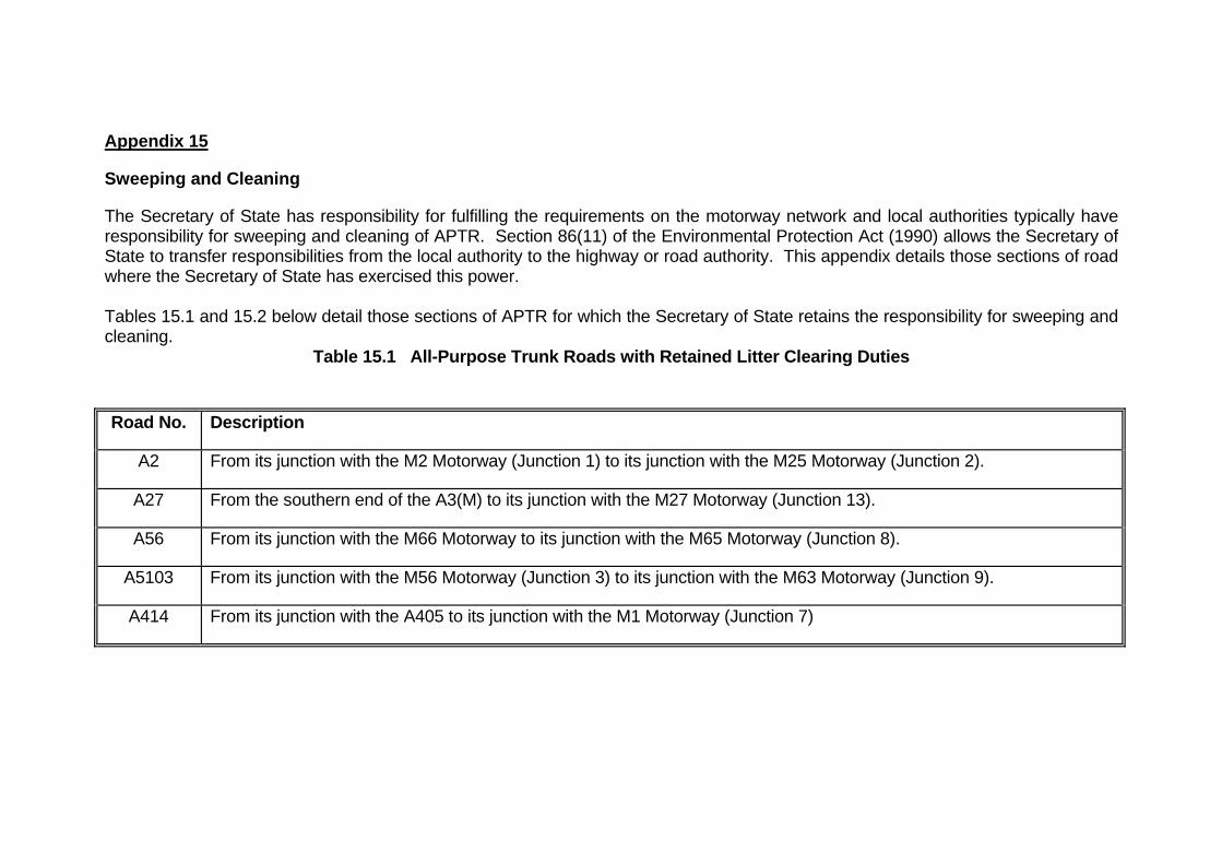
Appendix 15
Sweeping and Cleaning
The Secretary of State has responsibility for fulfilling the requirements on the motorway network and local authorities typically have responsibility for sweeping and cleaning of APTR. Section 86(11) of the Environmental Protection Act (1990) allows the Secretary of State to transfer responsibilities from the local authority to the highway or road authority. This appendix details those sections of road where the Secretary of State has exercised this power. Tables 15.1 and 15.2 below detail those sections of APTR for which the Secretary of State retains the responsibility for sweeping and cleaning.
Table 15.1 All-Purpose Trunk Roads with Retained Litter Clearing Duties
Road No. Description
A2 From its junction with the M2 Motorway (Junction 1) to its junction with the M25 Motorway (Junction 2).
A27 From the southern end of the A3(M) to its junction with the M27 Motorway (Junction 13).
A56 From its junction with the M66 Motorway to its junction with the M65 Motorway (Junction 8).
A5103 From its junction with the M56 Motorway (Junction 3) to its junction with the M63 Motorway (Junction 9).
A414 From its junction with the A405 to its junction with the M1 Motorway (Junction 7)

Table 15.2 All-Purpose Trunk Roads with Retained Litter Clearing Duties contracted to DBFO concessionaires
Road No. Description
A1 From a point 350 metres south of its junction with the Great North Road at Alconbury to a point 280 metres north of the Fletton Parkway Interchange.
A1 From a point 520 metres south of the Old Great North Road at Micklefield to a point 1 kilometre north of the A64(T) Leeds Road.
A1 From its junction with the A1(M) Junction 1 to the boundary between the Borough of Hertsmere and the London Borough of Barnet.
A2 From its junction with the M25 Motorway at junction 2 to the boundary between the Borough of Dartford and the London Borough of Bexley
A3 From its junction with the B2039 to the boundary between the Borough of Elmbridge and the Royal Borough of Kingston upon Thames.
A13 From its junction with the A1089 trunk road to the boundary between the Borough of Thurrock and the London Borough of Havering.
A14 From a point 420 metres south east of its junction with Rusts Lane to its junction with the A1 trunk road.
A19 From its junction with the A168 road at Thirsk to the roundabout at the junction with the A185 county road immediately south of the southern entrance to the Tyne Tunnel.

Road No. Description
A20 From its junction with the M25 Motorway at junction 3 to the boundary between the Sevenoaks District Council and the London Borough of Bromley.
A23 From its junction with the M23 at junction 7 to the boundary between the Borough of Reigate and Banstead and the London Borough of Croydon
A30 From its junction with the A308 to the boundary between the Borough of Spelthorne and the London Borough of Hounslow.
A30 From its junction with the M5 Motorway (Junction 29) to its junction with the A35 trunk road at Honiton.
A35 From its junction with the A30 trunk road at Honiton to the western leg of the roundabout at the junction of A35 and A31 trunk roads north east of Bere Regis.
A40 From its junction with the M40 Motorway at junction 1 to the boundary between South Buckinghamshire District Council and the London Borough of Hillingdon.
A50 From the boundary between the City of Stoke on Trent and the Borough of Stafford at the junction with the A521 county road to the junction with the A516 trunk road.
A66 From its junction with the A19 trunk road to a point 265 metres east of the overbridge to Teeside Retail Park in Stockton on Tees Borough Council.
A69 From its junction with the M6 Motorway (Junction 43) to its junction with the A1 trunk road (West Road Interchange).
A168 From a point 350 metres east of the county road overbridge located 650 metres east of the A1(M) bridge over the

Road No. Description
eastbound carriageway of the A168 trunk road at Dishforth to its junction with A19 trunk road at Thirsk.
A174 From its junction with the A19 trunk road at Parkway Interchange to the junction with the A1053 trunk road.
A249 From its junction with the M2 Motorway at junction 5 to its junction with the A250 (Sheerness)
A282 From its junction with the M25 Motorway (Junction 30) to its junction with the M25 Motorway (Junction 2).
A316 From its junction with the M3 Motorway at junction 1 to the boundary between the Borough of Spelthorne and the London Borough of Hounslow.
A405 From its junction with the M1 Motorway at junction 6 to its junction with the M25 Motorway at junction 21A.
A417 From its junction with the A419 trunk road to the grade separated junction at Ordnance Survey Grid Reference 388500E, 217600N near M5 (Junction 11a).
A419 From its junction with the M4 Motorway (Junction 15) to its junction with the A417 trunk road.
A1023 From its junction with the M25 Motorway at junction 28 to its junction with Brook Street Roundabout.
A1053 From its junction with the A174 trunk road to its junction with the A1085 County Road at Grangetown.
A1089 From its junction with the A13 trunk road to its boundary with the A126 at Tilbury Docks.
A3113 From its junction with the M25 Motorway at junction 14 to its junction with the A3044.

Please quote this HA Publications code: PR20/11
© Crown copyright 2011. You may re-use this information (not including logos) free of charge in
any format or medium, under the terms of the Open Government Licence. To view this licence, visit
http://www.nationalarchives.gov.uk/doc/open-government-licence/ or write to the Information Policy
Team, The National Archives, Kew, London TW9 4DU, or e-mail: [email protected].
Any enquiries regarding this document/publication should be sent to us at
[email protected] call 0300 123 5000
Highways Agency Media Services, Manchester N110103