hob identification methods
TRANSCRIPT
150
INTRODUCTION
In spite of the passage of time and a huge progress in toothing shaping technology, modular hobs continue to constitute the most popular tech-nology for machining spur gears or helical gears, racks, splines, belt transmissions, etc. [3,4]. The automotive industry, in particular, uses huge quantities of modular hobs of an increased length and number of teeth on the rack (leaf hobs) (Fig. 1b) [6]. The development in the design of CNC machine tools has contributed to the construction of special, composite hobs possible to be used in traditional machine tools [16–19]. Hobs with re-placeable plates are characterized by very good technological parameters, but lower accuracy compared to monolithic hobs. As a rule, these are hobs of classes B and A. In the case of the mono-lithic design, hobs in accuracy classes AA or AAA are standard. Machining with a hob with such ac-curacy makes it possible to shorten the techno-logical process and make a gear wheel through the elimination of additional operations and treat-ments. Modular hobs are produced of special tool alloys. In the case of small-module hobs designed for machining hard-machinable materials and heavy duty machining, monolithic hobs are con-structed, which are made of sintered carbides. As
a rule, both types are additionally coated with lay-ers that improve their machining properties and prolong the life of the hobs [6,16–19].
THE GEOMETRY AND TECHNOLOGY OF HOB EXECUTION
Hobs are among machining tools that are most difficult to design and make. Their geom-etry is very complex and requires the manufac-turer to perform many technological operations and treatments. The most important hob elements are toothed bars which, in the machining process, form a technological gear with the gear wheel be-ing machined [2,10]. As a result of hobbing, the rectilinear cutting edges of the hob form a char-acteristic, involute shape of the gear wheel tooth flank [3,4]. The classic hob is a backed-off tool (Fig. 1a) and has several to a dozen or so such toothed bars on its perimeter (depending on the module and diameter). Because of the heli-cal tool nature, they are twisted and inclined at the lead angle [2,10].
In the machining process, the hob forms a worm–gear wheel technological gear with the gear wheel being machined. The geometric analysis of so formed technological gear shows
HOB IDENTIFICATION METHODS
Andrzej Piotrowski1
1 Czestochowa University of Technology, Institute of Mechanical Technologies (ITM), Al. Armii Krajowej 21, 42-201 Częstochowa, Poland, e-mail: [email protected]
Advances in Science and TechnologyResearch JournalVolume 12, Issue 1, March 2018, pages 150–161DOI: 10.12913/22998624/81801
Research Article
ABSTRACTIn industrial practice, hobs are manufactured and used. The problem boils down to the identification of a hob with defining its profile, which depends on many design and technological parameters (such as the grinding wheel size, profile, type and position-ing during machining). This makes the basis for the correct execution and sharpening of the tool. The accuracy of the hob determines the quality of gear wheel teeth being shaped. The article presents hob identification methods that are possible to be used in industrial and laboratory practice.
Keywords: hob, accuracy, technology, metrology, CMM
Received: 2017.12.01Accepted: 2018.02.01Published: 2018.03.01

151
Advances in Science and Technology Research Journal Vol. 12 (1), 2018
that the surface of the technological worm mat-ing with the involute helical surface of the ma-chined gear wheel should be an involute helical surface [1,10].
The technological worm surface corresponds to the hob action surface, which is the locus of cutting edges. A cutting edge is formed by the intersection of the blade flank face with the rake face, whose form results from the technological process of hob blade shaping. For this reason, these surfaces determine the hob cutting edge profile and, as a consequence, the hob accuracy [7,10]. The involute helical surface is, on the other hand, a reference surface, with the profile of which the hob action surface profile can be
compared. A characteristic feature of the involute helical surface is the section tangential to the base cylinder, which is rectilinear.
In the classic technological process, the side flank faces and the rake face intersecting them are repeatedly ground and measured. After taking measurements, the grinding wheels are dressed, and the next grinding of the blade surface is done. By the method of successive approximations, the manufacturer attains the assumed accuracy of the hob.
The “trial and error” method is replaced with the use of a mathematical, computer hob model. The hob is designed using a specialized software program. The calculation result is all
a)
b)
Fig. 1. Monolithic hobs; a) classic type, b) leaf type [6].

Advances in Science and Technology Research Journal Vol. 12 (1), 2018
152
tools’ parameters and the program for forming (dressing) wormwheels for shaping hob surface . After having been made, the surfaces are mea-sured and, if necessary, corrected based on the measurements’ results. This implies that the hob measurement is an inseparable element of the technological process. The hob model is also used during the operation of the hob. The tool is subject to wear and, therefore, needs to be sharpened. In the process of sharpening, only the rake face is ground (the tool is backed off). The shape (profile) of the grinding wheel and its positioning relative to the rake surface being ground determine the correctness of the sharp-ening process [5,10]. The tool manufacturer does not provide information on the shape of the grinding wheel used for the final formation of the rake face. Therefore, before proceeding with sharpening, the hob should be identified by measuring its characteristic parameters. Af-ter the hob measurement, based on the devel-oped mathematical model, the profile of the unilaterally-tapered disc-type grinding wheel and its positioning with respect to the tool to be sharpened can be calculated.
ASSUMPTIONS AND THE EXAMINATION PROCEDURE
When analyzing the technological process and operation of the hob, the measuring methods used in industry and in laboratories for the mea-surements and identification of the tool condition were compared. A classic, monolithic hob was used for the measurements (Table 1).
The hob selected for investigation was sub-jected to the sharpening process. The classic rake face grinding method relying on the tracer-finger, the master and the unilaterally-tapered disc-type grinding wheel sharpened along the straight line in the axial profile was used. Manual sharpening of the hob, repeated several times, was performed. By the performed operation, a situation typical of industrial conditions was simulated. The user of the hob operated it following the technologi-cal rules and subjected it to a regular sharpening process using commercially available grinding wheels designed for rake face grinding [11]. After several cycles of sharpening under workshop con-ditions, he handed the tool over to a specialized shop to be correctly sharpened [2,5,10]. Before
Fig. 2. The engineering drawing of a hob with a module of m=6. (Author’s elaboration)
153
Advances in Science and Technology Research Journal Vol. 12 (1), 2018
proceeding with sharpening of a hob whose ac-tual parameters deviate from the nominal values, a series of measurements need to be performed to identify the hob. Classic, analogue measuring methods using a toolmaker’s microscope and a hob measuring machine, and coordinate methods using coordinate measuring machines with a con-tact and a measuring (scanning) heads were cho-sen to carry out the task.
Toolmaker’s microscope measurements
Notwithstanding the passage of time, one of the most common devices for hob identification in industrial conditions continues to be the large toolmaker’s microscope (Fig. 3a) equipped with additional instrumentation to enable the correct positioning of the tool in the support. The hob is fixed on the shaft and then put in prisms located on the microscope table. The traditional gonio-metrical measuring head is used for measure-ments (Fig. 3b). The measurement is taken in passing light. The preliminary procedure involves the organoleptic assessment of the hob condition, reading out the nominal hob parameters from the nameplate, counting the number of teeth, deter-mining the helix direction, counting the number of bars (grooves) and taking the measurement of geometrical parameters (length, diameter) by slide calliper or micrometric methods. On this basis, the operator calculates the remaining tool parameters.
Then, measurements were taken on the mi-croscope to verify the hob conditions, providing a basis for the selection of the grinding method and calculation of the grinding wheel profile. The measurement results showed considerable deviations from the nominal values. The follow-ing were consistent with the factory parameters: the nominal pitch, Pnom=21.924 mm; and the
pitch diameter tooth width, Bz=11.03 mm. The helix angle, γ=5°30’ (a difference of 1°), and the groove spiral lead, Sr=3427 mm (a difference of 781 mm), deviated significantly from the nominal values. The microscope does not allow the mea-surement of the cutting edge, only the assessment of its indentation. The measurements were taken at the Mikronar company of Radom, specializing in manufacturing and sharpening of machining tools. As a result of the performed identification, the company’s workers disqualified the hob, rec-ognizing it unfit to regenerate. No further mea-surements were taken.
Analogue measuring machines
In the 70s of the 20th century, special hob measuring machines were constructed. One of them, manufactured by Zeiss, is still part of the equipment of the Institute of Mechanical Tech-nologies (ITM) at the Czestochowa University of Technology. The principle of operation of mea-suring machines relies on establishing the appro-priate relation between the hob’s rotary motion and the gauging point motion parallel its axis. In the Zeiss measuring machine, these motions are accomplished by a mechanical means (Fig. 4). The travel of measuring slide 4 causes gear wheel 5 to back off along rack 6 and, as a result, the rota-tion of the hob being measured (Fig. 2), whereas, the displacement of the slide between the extreme position corresponds to five rotations of the hob (five-convolution hob). Depending on the hob pitch, cradle 8 should be positioned so that the sensor tip moves in measuring column 7 by the value of five pitches with the appropriate mea-suring slide displacement between the extreme positions. Preparation for working, operation and taking measurements on the Zeiss machine are all carried out manually and are very time-consum-
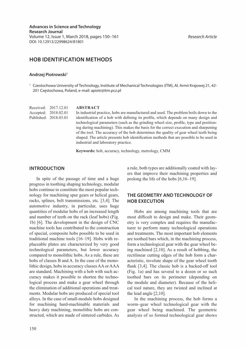
Table 1. The hob – parameters.
No. Nominal Unit1 Module m 7 mm2 Total length Da 90 mm3 Working length Dr 100 mm4 Nominal pitch Pnom 21.991 mm5 Tooth width on the pitch diameter Bz 10.995 mm6 Helix angle γ 4°29’ °7 Groove spiral lead Sr 4208 mm8 Number of convolutions 59 Helix direction right-hand
10 Number of cutting grooves 9

Advances in Science and Technology Research Journal Vol. 12 (1), 2018
154
ing. Recording the results takes place in an ana-logue manner using a special pen.
Using an induction sensor incorporated in rotary measuring column 7, connected with the micrometric screw and equipped with a special gauging point, the measurements of the rake face rectilinearity (Fig. 5a), the shape of the side flank faces at a distance of 1 mm from the cutting edge,
and the left-hand and right-hand cutting edge pro-files (Fig. 5b) were taken. The measurement is very time-consuming and requires the operator to take measurements repeatedly, depending on the selected measuring length, with the measurement result being recorded on the measuring tape in a form of “peaks”. Then, the manual identification, the numbering of “peaks” and their combination
a)
b)
Fig. 3. A large toolmaker’s microscope; a) hob fixture, b) measurement with the goniometric head. (Author’s elaboration)

155
Advances in Science and Technology Research Journal Vol. 12 (1), 2018
enable the cutting edge profile shape to be ob-tained. This method, due to the unavailability of the measuring tools, is used almost exclusively by hob manufacturers, and is extended by computer-ized recording that provides the capability to ob-tain the diagram of cutting edge deviations.
Coordinate measuring methods
The end of the 20th century was marked by an immense development of coordinate measur-ing methods. Computer controlled measuring ma-chines, collecting a cloud of measuring ball centre position points, in many cases replaced analogue measuring methods. At present, coordinate mea-suring machines are available in many companies and are used for ongoing dimensional verification of manufactured products [12,13]. When analyz-ing the possibility of using coordinate methods for hob identification, a Zeiss WMM 850 com-plete with a Zeiss VAST XXT passive scanning head mounted on it was used in coordinate mea-suring method (CMM) measurements. An addi-tional item of the machine equipment was a Zeiss RT 05–300 rotary table. The machine software consisted of the Zeiss Calypso, version 2015, and the Zeiss GEAR PRO HOB, version 2014, pro-grams [14,15]. The measurement was performed at the Zeiss Measurement Centre in Mikołów.
In contrast to analogue methods, the coordi-nate measurement starts from building the math-ematical model (coupled element) of the part to be measured. In the simplest case – a straight
line, mathematically two, and metrologically three points lying on the straight line will suffice to build the model. On this basis, an idealized straight line model is built, with which measure-ment results will then be compared [5,12,13,14]. Deviations from ideal dimensions are presented in a form of easily interpreted diagrams. A me-trologist can additionally determine the points de-viating most from the nominal values (maximal deviations) in the graph. The main operation of comparing the graphs is carried out in the com-puter’s operation memory [14].
Initial attempts to use coordinate machines for measuring hobs ended in failure. The build-ing of the model caused a number of very serious problems to the programmers. Only in 2010, to Sandvik’s order, Zeiss company extend the Zeiss Gear Pro gear wheel measuring program by add-ing a modular hob measuring module [15]. To operate with the program, a measuring machine equipped with a rotary table and featuring a mea-suring head is required. Theoretically, it is pos-sible to use a contact head, but in that case the time of the measurements and its complexity (ap-proach vectors) will increase several times. Due to the very complex geometry, the identification of the hob and, consequently, the building of the mathematical model of the hob requires the user to specify a very large number of parameters [15]. These shall conform to standard DIN 3968 or ISO 4468 [8,9]. The required quantities are identified organoleptically (the number of teeth, the num-ber of grooves), read out from the nameplate or
Fig. 4. A schematic diagram of the Zeiss machine for hobs: 1– motor, 2 – transmission, 3 – screw, 4 – measuring slide, 5 – gear wheel, 6 – rack, 7 – measuring column, 8 – cradle, 9 – coupling, 10 – worm. (Author’s elaboration)

Advances in Science and Technology Research Journal Vol. 12 (1), 2018
156
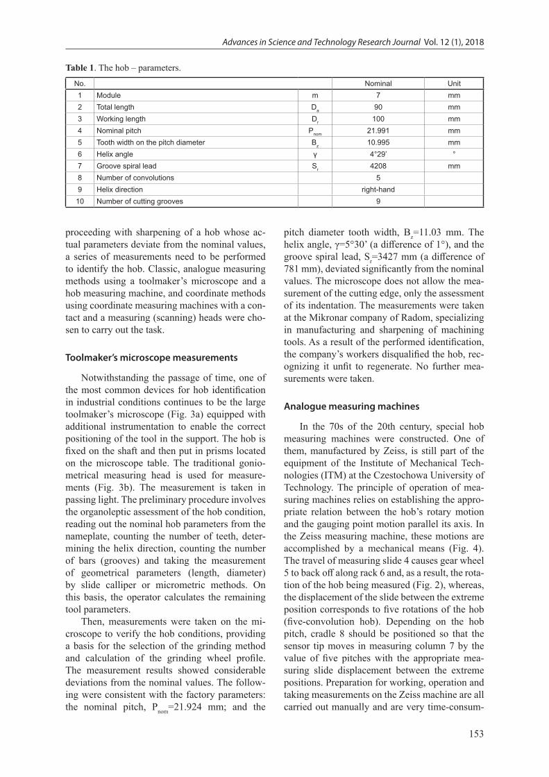
preliminarily measured with a micrometer. They are entered in the dialogue windows of the Zeiss Gear Pro Hob program (Fig. 6). After entering the parameters, the program computes the remain-ing geometric quantities from the mathematical relationships [15].
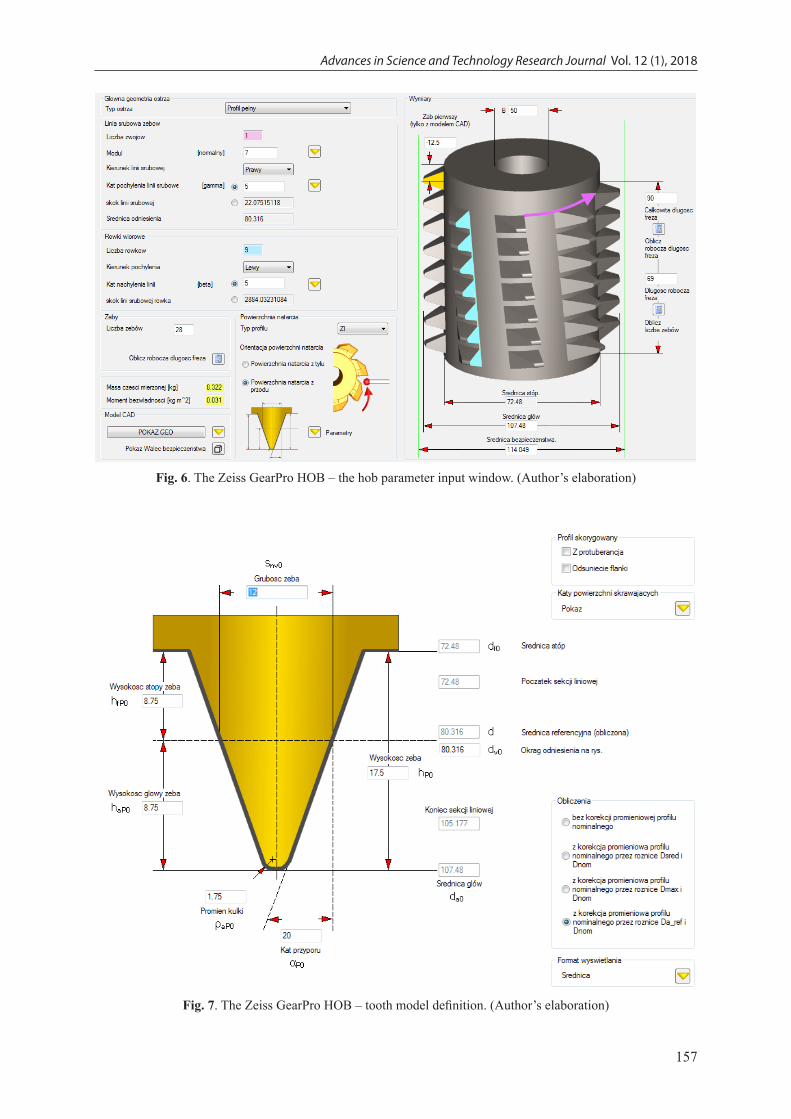
The program is universal and enables the def-inition of special hobs with a rack profile modifi-cation (Fig. 7). The final result is the generation of a mathematical coupled element, that is the 3D hob model. It provides the basis for comparison with actual dimensions obtained from the mea-suring process. The Zeiss software stores both models – the reference model and the actual mod-el obtained from the measuring procedure – in the memory [14,15].
The next stage of hob identification is the definition of the measuring strategy that is the de-termination of the approach direction, the contact direction along with corrections, the approach
mode, the tooth measurement range, the scanning range, the selection of the reference standard, the tolerance class, and the choice of the gauge plung-er. The measurements were done with a gauging point ended with a 2 mm-diameter ball.
The measuring procedure starts with the po-sitioning of the gauging point above the surface to be measured. In the automatic mode, the gaug-ing point moves towards the hob tooth point and comes into contact with the rake face. During the measurement, it moves down (towards the chip clearance). At the same time, the table makes a rotation, as a result of which the gauging point moves along a helix. As the measurement is tak-en, it moves over the rake face in parallel to the hob axis, at the pitch diameter height. Upon ap-proaching the cutting edge, a drop takes place. The program records this moment and, using the mathematical ball radius compensation and the 3D hob model, computes the width of pitch
a)
b)
Fig. 5. The hob measuring machine. Measurement results: a) rake face, b) cutting edge profile. (Author’s elaboration)
157
Advances in Science and Technology Research Journal Vol. 12 (1), 2018
Fig. 6. The Zeiss GearPro HOB – the hob parameter input window. (Author’s elaboration)
Fig. 7. The Zeiss GearPro HOB – tooth model definition. (Author’s elaboration)
Advances in Science and Technology Research Journal Vol. 12 (1), 2018
158
tooth diameter . Interestingly enough, the cutting edge position identification and pitch diameter tooth width measurement methods are identical to those for the classic analogue methods of hob measurement on dedicated machines.
During the course of the measurement it turned out that the head passed into the working travel mode at a varying distance from the tooth root, and upon measuring the upper cutting edge at the time when the gauging point was supposed to come into contact with the hob at the root di-ameter height, the machine detected a collision. The cause was the hob sharpening procedure carried out prior to the measurements. The large difference between the parameters preset in the software and the actual parameters resulted in the creation of a model, which significantly deviated from the true hob dimensions. Another obstacle was the fact of the automatic change of individ-ual hob parameters during the course of entering some quantities, which was due to the 3D model building algorithm used by the programmers.
Knowing the incorrectly made hob correc-tion, it was necessary to find parameters which
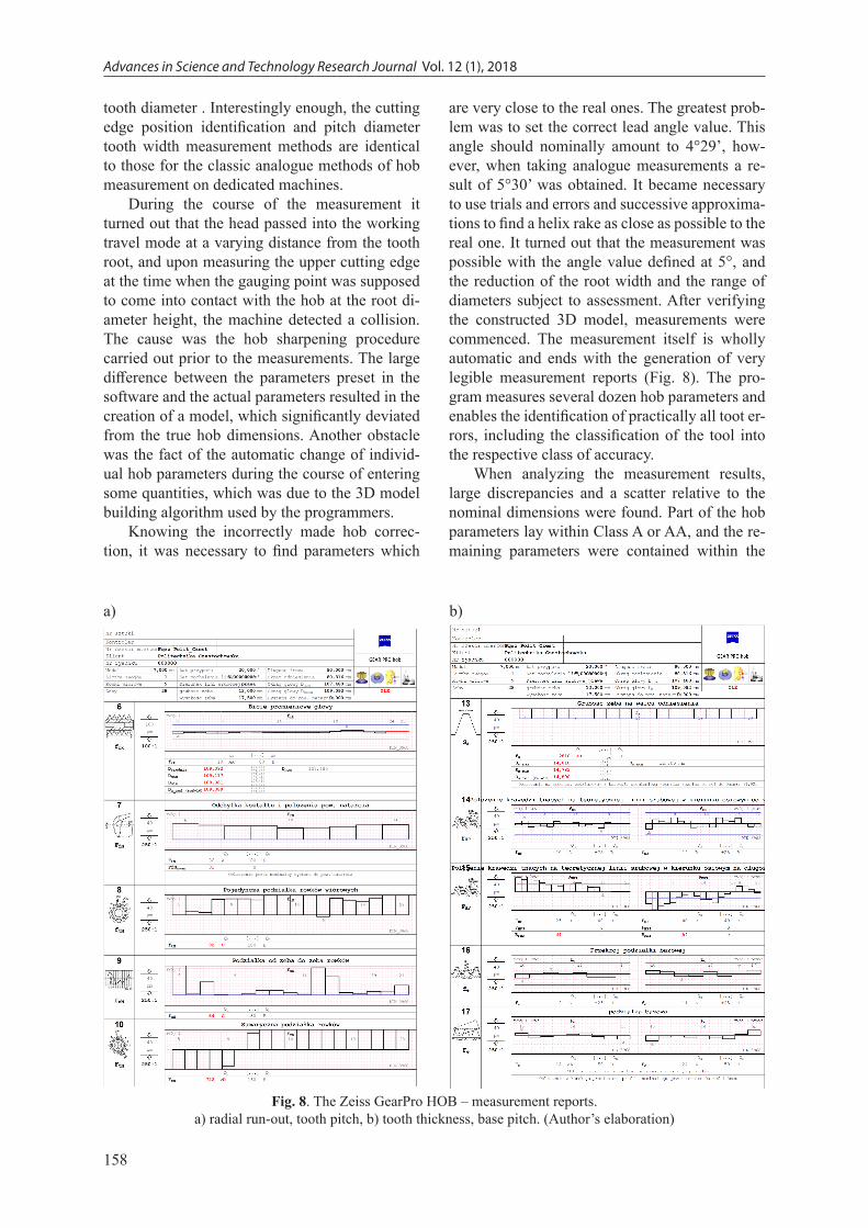
are very close to the real ones. The greatest prob-lem was to set the correct lead angle value. This angle should nominally amount to 4°29’, how-ever, when taking analogue measurements a re-sult of 5°30’ was obtained. It became necessary to use trials and errors and successive approxima-tions to find a helix rake as close as possible to the real one. It turned out that the measurement was possible with the angle value defined at 5°, and the reduction of the root width and the range of diameters subject to assessment. After verifying the constructed 3D model, measurements were commenced. The measurement itself is wholly automatic and ends with the generation of very legible measurement reports (Fig. 8). The pro-gram measures several dozen hob parameters and enables the identification of practically all toot er-rors, including the classification of the tool into the respective class of accuracy.
When analyzing the measurement results, large discrepancies and a scatter relative to the nominal dimensions were found. Part of the hob parameters lay within Class A or AA, and the re-maining parameters were contained within the
a) b)
Fig. 8. The Zeiss GearPro HOB – measurement reports. a) radial run-out, tooth pitch, b) tooth thickness, base pitch. (Author’s elaboration)

159
Advances in Science and Technology Research Journal Vol. 12 (1), 2018
deviation limits characteristic of Class C. The largest error was observed for the lead angle of grooves over a length of 100 mm. In spite of ex-perimentally establishing the angle value at 5°, the diagram of deviations was totally incorrect (Fig. 9b). The analysis of the diagram showed that, in the grinding process, either the grinder in-correctly led the tracer-finger over the template, or, what is more likely, the template was not cor-rect – the lead angle was different. The lead angle error resulted in an incorrect value of the pitch di-ameter tooth width. The nominal value resulting from calculation is 12 mm, while the measured value is 14.2 mm. The lead angle error has also an effect on many other hob parameters. Practically, consistent with the nominal values were devia-tions of tooth form profile (Fig. 9a). This was due to the fact that the hob is sharpened only along the rake face, and the both flank faces are formed by the manufacturers. The errors were contained within the limits of deviations for a hob of Class B (according to the nameplate). The measurement on the coordinate machine showed clearly that a rectilinear-profile grinding wheel had been used
for rake face sharpening. A characteristic bulgi-ness error is visible in the diagram (Fig. 9b).
The measurement reports enable a very accu-rate hob identification. Based on the diagram of the position and shape of the rake face, its error can be corrected by calculating the correct grind-ing wheel profile. A much more difficult problem is to uniquely identify and interpret the lead angle error. Practically, the only method of eliminating the error is by setting the grinding wheel accord-ing to the nominal value, and then performing grinding and a repeated measurement. To sum up, the measurement using a coordinate machine and specialized software is the most accurate and the fastest to take. The measurement accuracy is, however, dependent on the quality of the coupled element, that is the 3D model.
CONCLUSIONS AND PRACTICAL RECOMMENDATIONS
The basic aim of the investigation was to ana-lyze the most popular methods of identification
a) b)
Fig. 9. The Zeiss GearPro HOB – measurement reports. a) tooth form, b) rake face rectilinearity (Author’s elaboration)

Advances in Science and Technology Research Journal Vol. 12 (1), 2018
160
of hobs under laboratory and workshop condi-tions. A specially formed (incorrectly sharpened) hob allowed some problems to be discovered during measurements. A common feature of all measuring methods was a two-stage mode. The first stage consists of the visual and organoleptic assessment and analysis of the nominal features. In each case, the number of teeth, the number of chip clearances (toothed bars) and the number of convolutions need to be manually counted, the lead angle needs be read, and the tool surface quality (cutting edge indentation) needs to be as-sessed. The second step is dependent on the se-lected measuring method and boils down to the manual and automatic counting of the basic hob parameters dependent on the basic parameters, and the measurement of the hob.
When operating a hob, the user has a task to solve, which is opposite to that of the manufac-turer’s. On the basis of metrological analysis he has to define the shape (profile) and positioning of the rake face forming grinding wheel that is to build a model based on the measurements. The manufacturer first designs the hob – creates the 3D model in CAD programs, and on its basis, he plans the technological process. He can practi-cally arbitrarily correct the profile of both flank faces and rake faces. The overriding goal is to obtain the correct cutting edge. Unfortunately, he does not specify the profile of the grinding wheel, with which he finally formed the rake face. The performed measurements allow the user to only roughly define this profile.
The easiest to interpret and most accurate are the measurement results obtained on the coordi-nate measuring machine using the Zeiss GearPro HOB software. This is a unique software applica-tion. The specially formed (erroneous) hob used in the investigation has starkly revealed the ba-sic problem of coordinate measurements. This is the building of the coupled element, that is the 3D hob model. The results of measurements and the troubles encountered during taking them ex-plicitly indicate the cause of the errors. Because the hob was incorrectly sharpened, both the lead angle and the rake face shape changed. By build-ing the 3D model based on the nominal data, we obtain an incorrect tool shape and, as a conse-quence, the CMM movement control algorithm is erroneous and, in many instances, makes mea-surements impossible to take. The Zeiss GearPro HOB program does not measure the profile of the cutting edges that determine the hob accuracy.
It should be emphasized that the measurement results obtained by three different methods coin-cided. Even the simplest toolmaker’s microscope enabled the correct identification of the hob. Un-fortunately, it only allowed the measurement of the basic hob parameters. The analysis showed that the only instrument that allowed the cutting edge profile to be obtained, was the analogue hob measuring machine. Unfortunately, it is rarely found in industry, and the measurement process is long-lasting and requires trained personnel.
The basic, but the most important, conclusion resulting from the analysis of the hob identifica-tion methods is the postulate (requirement) that the tool manufacturer should provide additional tool data, and in particular the profile and the angle of positioning of the grinding wheel used for forming the rake face. This would result in an increase in the tool’s life and an improvement of its accuracy during operation.
REFERENCES
1. Bouzakis K.D., Lili E., Michalidis N., Friderikos O.: Manufacturing of cylindrical gears by gen-erating cutting processes: A critical synthesis of analytical methods, CIRP Annals – Manufacturing Technology 57, 2008, pp 676–696.
2. Cichosz P.: Narzędzia skrawające [Cutting tools], WNT Publishers, Warsaw 2006, 2013.
3. Dimitriou V., Antoniadis A.: CAD+based simula-tion of the hobbing process for the manufacturing of spur and helical gears. Int J Adv Manuf Technol 2009, 41, pp 347–357.
4. Dzierżkowski A.: Frezowanie obwiedniowe wal-cowych kół zębatych [Hobbing of spure gears], Scientific and Technical Publishers, Warsaw 1972.
5. Hulboj S.: Regeneracja i pomiary narzędzi skrawających [The regeneration and measure-ments of cutting tools], University Press of the Czestochowa University of Technology, Czesto-chowa 1997.
6. LMT Technology Group: Fette Gear Cutting Tools and Knowledge, Catalogue, www.lmt-tools.com, Germany 2017
7. Nieszporek T., Piotrowski A.: Enhancing the Accu-racy of Composite Hobs, XXI Polish-Slovak Sci-entific Conference Machine Modeling and Simula-tions (MMS 2016), Hucisko, Polska 2016
8. Standard DIN 3968:1960–09: Tolerances for Sin-gle-start Hobs for Involute Spur Gears
9. Standard PN-ISO 4468:1999: Frezy ślimakowe jednokrotne do kół zębatych – Wymagania

161
Advances in Science and Technology Research Journal Vol. 12 (1), 2018
dokładności [Single hobs for gear wheels -- Qual-ity requirements] (in Polish)
10. Piotrowski A.: Podwyższenie dokładności frezów ślimakowych modułowych [Enhancing the accu-racy of modular hobs], Czestochowa University of Technology, Czestochowa 2002.
11. Piotrowski A.: Wpływ ostrzenia na dokładność frezów ślimakowych modułowych [The effect of sharpening on the accuracy of modular hobs], Mechanik, R.88/7, pp. 681–694, Warsaw 2015. (in Polish)
12. Ratajczak E., Woźniak A.: Współrzędnościowe systemy pomiarowe [The coordinate measuring systems], University Press of the Warsaw Univer-sity of Technology, Warsaw 2016.
13. Ratajczak E.: Współrzędnościowa technika po-
miarowa [The coordinate measuring technique], University Press of the Warsaw University of Technology, Warsaw 2005.
14. ZEISS: Calypso, The Program’s User Manual, Zeiss, Germany 2014.
15. ZEISS: Gear Pro Hob, Instrukcja programu, Zeiss, Germany 2014.
16. http://3dcad.pl/aktualnosci/5797/coromill-176-sk-raca-czas-frezowania-kol-zebatych-o-polowe.html (in Polish) (may 2017)
17. http://www.sandvik.coromant.com/en-gb/prod-ucts/coromill_172/Pages/default.aspx (may 2017)
18. http://www.sandvik.coromant.com/en-gb/prod-ucts/coromill_176/Pages/default.aspx (may 2017)
19. http://www.sandvik.coromant.com/en-gb/prod-ucts/coromill-177/Pages/default.aspx (may 2017)