honeywell unisim europe 2012
TRANSCRIPT
Customising UniSim Design®: membrane separa5on and its applica5on
to carbon capture Davide Bocciardo University of Edinburgh , Ins9tute for Materials and Processes, Edinburgh SCCS – Sco@sh Carbon Capture and Storage Centre
UniSim Design Challenge 2012
Honeywell users group 2012
Outline
• CCS, carbon capture and membranes • Problem defini9on • Modelling • Complete integra9on into UniSim Design® • Mul9-‐stage design • From engineering to economic analysis • Conclusions and challenges
UniSim Design Challenge 2012 Davide Bocciardo 2

CCS and coal
UniSim Design Challenge 2012 Davide Bocciardo 3
CO2 is one of the main contributors to global warming: temperatures are expected to rise by 1 to 3° C in the next century1
• Combus9on of fossil fuels will s9ll play a key role for energy genera9on in the next decades: coal-‐fired power plants are among the biggest CO2 emiQers
• CCS -‐ Carbon Capture and Storage -‐ is bound to give a drama9c contribu9on to the reduc9on of CO2 emissions, in addi9on to renewable energies
• UK target2: reduc9on of CO2 emissions by 34 % of 1990 levels by 2020 1. h:p://www.ipcc.ch 2. h:p://www.decc.gov.uk/

Membranes and carbon capture
UniSim Design Challenge 2012 Davide Bocciardo 4
• Advantages: modular process, no solvents and regenera9on apparatus
• Disadvantages: low selec9vi9es for commercial membranes and low CO2 concentra9on in the flue gas
Zhao et al., Journal of membrane Science, 359 (2010)
Membrane separa9ons can be applied to the post-‐ combus9on capture of CO2 as alterna9ve to solvent-‐based capture processes (ex. amines), the conven9onal capture op9on

Problem defini5on
UniSim Design Challenge 2012 Davide Bocciardo 5
• Formula9on and numerical implementa9on of a mathema9cal steady-‐state model able to predict the separa9on through a membrane permeator
• Integra9on of the new model into a simula9on environment – UniSim Design®
• Crea9on of a completely automated interface developed as a common unit opera9on
• Complete process simula9on to evaluate the feasibility of membrane separa9on for carbon capture

A membrane module
UniSim Design Challenge 2012 Davide Bocciardo 6
• A membrane is a system which selec9vely allows the flux of certain components • The permeability is the ability of a component to permeate through the film • The driving force for the separa9on can be expressed as the difference in par9al
pressure between the 2 sides of the compartment • A membrane module is a device where a certain membrane area is assembled
according to a specific configura9on (hollow fibre, flat sheet, spiral-‐wound, etc.).
Feed
Permeate
Retentate

Modelling
UniSim Design Challenge 2012 Davide Bocciardo 7
• The main aim is predic9ng the performances of industrially available permeators • Different models available in the literature have been analysed and compared • Counter-‐current with sweep has been iden9fied as ideal for high-‐recovery stages
Feed
Permeate
Retentate
Sweep
• A 2D cross-‐flow model has also been implemented to predict the separa9on through spiral-‐wound permeators: it is ideal for high-‐purity stages
Why sweep? It increases the par9al pressure difference à higher flux Industrial applicaQon: hollow fibre modules
R. Baker “Membrane technology and applicaQons”, Wiley (2004)

UniSim integra5on: the interface
UniSim Design Challenge 2012 Davide Bocciardo 8
• The implementaQon has been carried out with a C compiler linked to open sources libraries1
• The numerical resolu9on is based on both finite differences and orthogonal colloca9ons on finite elements methods
The key step is the integra9on into the simula9on environment: • A C++ code has been built as a shell for the unit opera9on • The connec9ons between the UniSim flowsheet and the code have
been enabled and tested • The error messages have been customised • The UniSim icons and the user interface (.edf file) have been created
1. Serban, R., C. Woodward, et al. (2009). "h:ps://computaQon.llnl.gov/casc/sundials/main.html."

Membrane_UoE
UniSim Design Challenge 2012 Davide Bocciardo 9
1) The C++ code: the customised subrou9nes are added to the standard C++ files. The connec9ons between the source code and the UniSim flowsheet are defined
3) The unit opera9on is available from the main menu and it can be used to run simula9ons. No external windows are open during the simula9on.
2) The project is built as a .dll: it can be registered into the UniSim environment

Membrane_UoE
UniSim Design Challenge 2012 Davide Bocciardo 10
• The pre-‐developed code has been kept in the original formula9on and it has been included in the interface
• Membrane_UoE is completely integrated into the simula9on environment • A user-‐friendly interface helps the user to run simula9ons
• By following the same procedure, any kind of steady-‐state external tool can be designed • Only a C++ compiler (ex. Dev C++) and open-‐source libraries are required

Mul5-‐stage analysis
UniSim Design Challenge 2012 Davide Bocciardo 11
• Carbon capture goals: 90% CO2 recovery and CO2 purity above 95% • A hypothe9cal material combining op9mal proper9es has been
chosen • A single membrane stage is not able to meet the desired
requirements for the separa9on • A mul9-‐stage process design has been studied star9ng from a
power plant simula9on (DOE1 case 9 – subcri9cal coal-‐fired power plant) developed by our research group
• A study of the possible configura9ons has been carried out to show the poten9al of the membrane separa9on for a large scale applica9on
1. Cost and Performance Baseline for Fossil Energy Plants, US Department Of Energy (2007)

Complete UniSim flowsheet
UniSim Design Challenge 2012 Davide Bocciardo 12
Power plant Capture scheme
Compression

Retrofit Op5on
UniSim Design Challenge 2012 Davide Bocciardo 13
• The flue gas (CO2 ~ 13% mol/mol) is directly sent to a countercurrent (with sweep) high-‐recovery stage 1 and then to a cross-‐flow high-‐purity stage 2
• Sweep and recycles play a key role in the overall process design
• High purity (~ 85 % mol/mol) CO2 from stage 2 is compressed up to 30 bar and a refrigera9on stage is added before compressing the CO2 to 150 bar
Compression train
RefrigeraQon

Boiler Op5on
UniSim Design Challenge 2012 Davide Bocciardo 14
• Both energy consump9on and membrane area are reduced due to the higher CO2 content in the flue gas (~ 18% mol/mol)
Merkel et al., Journal of Membrane Science, 359 (2010)
• A high-‐recovery counter-‐current stage 1 with air as sweep is added: the permeate is directly sent as feed to the boiler (CO2 ~ 3 % mol/mol)
Air Air + CO2
CO2 + N2 N2
CO2
Compression train
RefrigeraQon

Economic analysis: LCOE
UniSim Design Challenge 2012 Davide Bocciardo 15
Levelised Cost of Electricity (LCOE) is the ra9o of the net present value of total capital and opera9ng costs of a par9cular plant to the net present value of the net electricity generated by that plant over its opera9ng life1
Why LCOE? • Its rela9ve increase is significant for the overall evalua9on of the
technology • It is less dependent on the market basis than the capture costs
calcula9ons available in the literature for membranes2,3 A complete evalua9on including a base-‐case and a calcula9on for both membrane and amine capture contribu9on has been carried out4,5
1. Electricity GeneraQon Cost Model – 2011 Update revision 1 – DECC 2. Merkel et al. Journal of Membrane Science, 359 (2010) 3. Zhao et al., Journal of Membrane Science 359 (2010) 4. The costs of CO2 capture – Zero Emission Pladorm (2009) 5. Cost and Performance of Carbon Dioxide Capture from Power GeneraQon, IEA -‐ InternaQonal Energy Agency.
Economic analysis: LCOE
UniSim Design Challenge 2012 Davide Bocciardo 16
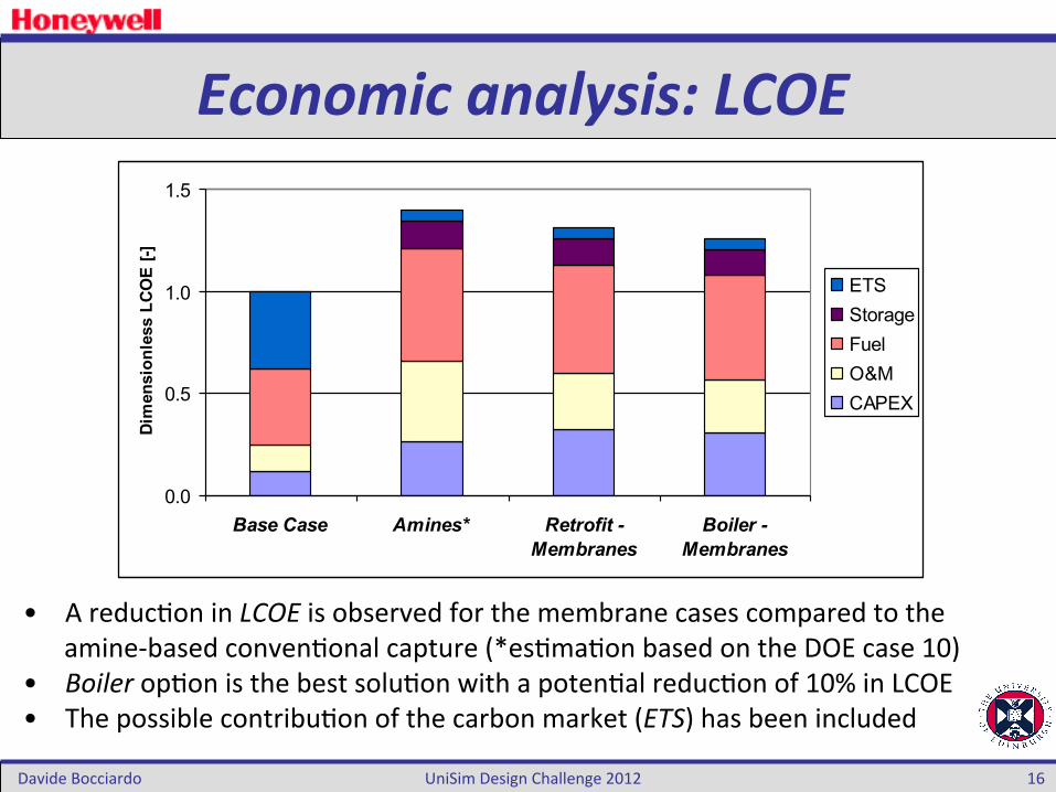
• A reduc9on in LCOE is observed for the membrane cases compared to the amine-‐based conven9onal capture (*es9ma9on based on the DOE case 10)
• Boiler op9on is the best solu9on with a poten9al reduc9on of 10% in LCOE • The possible contribu9on of the carbon market (ETS) has been included
0.0
0.5
1.0
1.5
Base Case Amines* Retrofit -Membranes
Boiler -Membranes
Dim
ensi
onle
ss L
COE
[-]
ETSStorageFuelO&MCAPEX

Conclusion and challenges
UniSim Design Challenge 2012 Davide Bocciardo 17
• In the direc9on of reducing CO2 emissions from coal-‐fired power plant, membrane separa9on may play a key role
• The customisa9on of UniSim® Design allows a complete es9ma9on of the separa9on and the implementa9on of addi9onal customised unit opera9ons
• LCOE is a useful economic parameter, par9cularly for long-‐term predic9ons such as CCS perspec9ves
• More detailed models are under inves9ga9on in order to give more realis9c predic9ons
• Future challenges will involve the dynamic implementa9on and customisa9on
UniSim Design Challenge 2012 Davide Bocciardo 18
Thanks for your aQen5on
Acknowledgements: • ETP (Energy Technology Partnership) and ScoDsh Power for funding this project • PhD supervisors: Prof. Stefano Brandani and Dr. Maria-‐Chiara Ferrari • Dr. Friedrich for his mathema9cal and programming support