hopper scale - chore-time · an officer of ctb, inc. must authorize any exceptions to this warranty...
TRANSCRIPT

Hopper ScalePart Number 46280
Installation Manual
1677-46 2/2001
MF1677AMarch 2001

Chore-Time Warranty Hopper Scale
Chore-Time Equipment (“Chore-Time”) warrants each new Chore-Time product manufactured by it to be free from defects in material or workmanship for one year from and after the date of initial installation by or for the original purchaser. If such a defect is found by the Manufacturer to exist within the one-year period, the Manufacturer will, at its option, (a) repair or replace such product free of charge, F.O.B. the factory of manufacture, or (b) refund to the original purchaser the original purchase price, in lieu of such repair or replacement. Labor costs associated with the replacement or repair of the product are not covered by the Manufacturer.
Conditions and Limitations1. The product must be installed by and operated in accordance with the instructions published by the
Manufacturer or Warranty will be void.
2. Warranty is void if all components of the system are not original equipment supplied by the Manufacturer.
3. This product must be purchased from and installed by an authorized distributor or certified representative thereof or the Warranty will be void.
4. Malfunctions or failure resulting from misuse, abuse, negligence, alteration, accident, or lack of proper maintenance shall not be considered defects under the Warranty.
5. This Warranty applies only to systems for the care of poultry and livestock. Other applications in industry or commerce are not covered by this Warranty.
The Manufacturer shall not be liable for any Consequential or Special Damage which any purchaser may suffer or claim to suffer as a result of any defect in the product. “Consequential” or “Special Damages” as used herein include, but are not limited to, lost or damaged products or goods, costs of transportation, lost sales, lost orders, lost income, increased overhead, labor and incidental costs and operational inefficiencies.
THIS WARRANTY CONSTITUTES THE MANUFACTURER’S ENTIRE AND SOLE WARRANTY AND THIS MANUFACTURER EXPRESSLY DISCLAIMS ANY AND ALL OTHER WARRANTIES, INCLUDING, BUT NOT LIMITED TO, EXPRESS AND IMPLIED WARRANTIES AS TO MERCHANTABILITY, FITNESS FOR PARTICULAR PURPOSES SOLD AND DESCRIPTION OR QUALITY OF THE PRODUCT FURNISHED HEREUNDER.
Chore-Time Distributors are not authorized to modify or extend the terms and conditions of this Warranty in any manner or to offer or grant any other warranties for Chore-Time products in addition to those terms expressly stated above. An officer of CTB, Inc. must authorize any exceptions to this Warranty in writing. The Manufacturer reserves the right to change models and specifications at any time without notice or obligation to improve previous models.
Effective: June 2001
Chore-Time EquipmentA Division of CTB, Inc.
P.O. Box 2000 • Milford, Indiana 46542-2000 • U.S.A.Phone (219) 658-4101 • Fax (877) 730-8825
Email: [email protected] • Internet: http//www.ctbinc.com
Thank You
The employees of Chore-Time Equipment would like to thank your for your recent Chore-Time purchase. If a problem should arise, your Chore-Time distributor can supply the necessary information to help you.
Chore-Time Warranty
2 MF1677A

Contents
Topic Page
Chore-Time Warranty . . . . . . . . . . . . . . . . . . . . . . . . . . . . . . . . . . . . . . . . . . . . . . . . . . . . . . . . . . . . 2
General. . . . . . . . . . . . . . . . . . . . . . . . . . . . . . . . . . . . . . . . . . . . . . . . . . . . . . . . . . . . . . . . . . . . . . . . . 4Support Information . . . . . . . . . . . . . . . . . . . . . . . . . . . . . . . . . . . . . . . . . . . . . . . . . . . . . . . . . . . . . . . . . . . 4
About This Manual. . . . . . . . . . . . . . . . . . . . . . . . . . . . . . . . . . . . . . . . . . . . . . . . . . . . . . . . . . . . . . . 4
Safety Information . . . . . . . . . . . . . . . . . . . . . . . . . . . . . . . . . . . . . . . . . . . . . . . . . . . . . . . . . . . . . . . 4
Safety Instructions . . . . . . . . . . . . . . . . . . . . . . . . . . . . . . . . . . . . . . . . . . . . . . . . . . . . . . . . . . . . . . . 5Follow Safety Instructions . . . . . . . . . . . . . . . . . . . . . . . . . . . . . . . . . . . . . . . . . . . . . . . . . . . . . . . . . . . . . . 5Decal Descriptions . . . . . . . . . . . . . . . . . . . . . . . . . . . . . . . . . . . . . . . . . . . . . . . . . . . . . . . . . . . . . . . . . . . . 5
DANGER: Moving Auger. . . . . . . . . . . . . . . . . . . . . . . . . . . . . . . . . . . . . . . . . . . . . . . . . . . . . . . . . . . 5DANGER: Electrical Hazard . . . . . . . . . . . . . . . . . . . . . . . . . . . . . . . . . . . . . . . . . . . . . . . . . . . . . . . . 5
Assembling the Hopper Scale . . . . . . . . . . . . . . . . . . . . . . . . . . . . . . . . . . . . . . . . . . . . . . . . . . . . . . 6Locating the Parts . . . . . . . . . . . . . . . . . . . . . . . . . . . . . . . . . . . . . . . . . . . . . . . . . . . . . . . . . . . . . . . . . . . . . 6Assemble the Shut-Off Gate . . . . . . . . . . . . . . . . . . . . . . . . . . . . . . . . . . . . . . . . . . . . . . . . . . . . . . . . . . . . . 6Assemble the Boot Extension and Lower Switch. . . . . . . . . . . . . . . . . . . . . . . . . . . . . . . . . . . . . . . . . . . . . 7Assemble the Scale Platform . . . . . . . . . . . . . . . . . . . . . . . . . . . . . . . . . . . . . . . . . . . . . . . . . . . . . . . . . . . . 8Suspending the Scale Platform . . . . . . . . . . . . . . . . . . . . . . . . . . . . . . . . . . . . . . . . . . . . . . . . . . . . . . . . . . .10Assemble the Hopper . . . . . . . . . . . . . . . . . . . . . . . . . . . . . . . . . . . . . . . . . . . . . . . . . . . . . . . . . . . . . . . . . .11
300 lb. [136 kg] Hopper. . . . . . . . . . . . . . . . . . . . . . . . . . . . . . . . . . . . . . . . . . . . . . . . . . . . . . . . . . . . .11200 lb. [91 kg] Hopper. . . . . . . . . . . . . . . . . . . . . . . . . . . . . . . . . . . . . . . . . . . . . . . . . . . . . . . . . . . . . .12
Install the Shut-Off Gate Assembly to the Feed Hopper . . . . . . . . . . . . . . . . . . . . . . . . . . . . . . . . . . . . . . .13Install Feed Hopper to Scale Platform . . . . . . . . . . . . . . . . . . . . . . . . . . . . . . . . . . . . . . . . . . . . . . . . . . . . .14Zeroing the Hopper Scale . . . . . . . . . . . . . . . . . . . . . . . . . . . . . . . . . . . . . . . . . . . . . . . . . . . . . . . . . . . . . . .15Wiring Diagram . . . . . . . . . . . . . . . . . . . . . . . . . . . . . . . . . . . . . . . . . . . . . . . . . . . . . . . . . . . . . . . . . . . . . .15
Start Up Check List . . . . . . . . . . . . . . . . . . . . . . . . . . . . . . . . . . . . . . . . . . . . . . . . . . . . . . . . . . . . . 17
Operating the Hopper Scale Assembly . . . . . . . . . . . . . . . . . . . . . . . . . . . . . . . . . . . . . . . . . . . . . . 18
Parts Listing . . . . . . . . . . . . . . . . . . . . . . . . . . . . . . . . . . . . . . . . . . . . . . . . . . . . . . . . . . . . . . . . . . . 19Switch Assembly Part Number 46273 . . . . . . . . . . . . . . . . . . . . . . . . . . . . . . . . . . . . . . . . . . . . . . . . . . . . .19Hanging Scale Part Number 46280 . . . . . . . . . . . . . . . . . . . . . . . . . . . . . . . . . . . . . . . . . . . . . . . . . . . . . . .20Beam Bar Assembly Part Number 46279. . . . . . . . . . . . . . . . . . . . . . . . . . . . . . . . . . . . . . . . . . . . . . . . . . .20Shut-Off Gate Assembly Part Number 46226 . . . . . . . . . . . . . . . . . . . . . . . . . . . . . . . . . . . . . . . . . . . . . . .21Lower Hopper Switch Assembly Part Number 8798 . . . . . . . . . . . . . . . . . . . . . . . . . . . . . . . . . . . . . . . . . .22
MF1677A 3

General Hopper Scale
Support InformationThe Chore-Time Hopper Scale is designed to provide a way to supply a measured amount of feed to a floor feeding system. Using this equipment for any other purpose or in a way not within the operating recommendations specified in this manual will void the warranty and may cause personal injury.
This manual is designed to provide comprehensive planning and installation information. The Table of Contents provides a convenient overview of the information in this manual.
The intent of this manual is to help you in two ways. One is to follow step-by-step in the order of assembly of your product. The other way is for easy reference if you have questions in a particular area.
Important !Read ALL instructions carefully before starting construction.
Important !Pay particular attention to all SAFETY information.
• Metric measurements are shown in millimeters and in brackets, unless otherwise specified. “ " ” equals inches and “ ' ” equals feet in English measurements.Examples: 1" [25.4]4' [1 219]
• Optional equipment contains necessary instructions for assembly or operation.
• Major changes from the last printing will be listed on the back cover.
•This Planning Symbol is used in areas where planning needs to take place before construction continues.
• Very small numbers near an illustration (i.e., 1257-48) are identification of the graphic, not a part number.
Caution, Warning and Danger Decals have been placed on the equipment to warn of potentially dangerous situations. Care should be taken to keep this information intact and easy to read at all times. Replace missing or damaged safety decals immediately.
Using the equipment for purposes other than specified in this manual may cause personal injury and/or damage to the equipment.
General
About This Manual
Safety Information
4 MF1677A

Hopper Scale Safety Instructions
Safety–Alert SymbolThis is a safety–alert symbol. When you see this symbol on your equipment, be alert to the potential for personal injury. This equipment is designed to be installed and operated as safely as possible...however, hazards do exist.
Understanding Signal WordsSignal words are used in conjunction with the safety–alert symbol to identify the severity of the warning.
DANGER indicates an imminently hazardous situation which, if not avoided, WILL result in death or serious injury.
WARNING indicates a potentially hazardous situation which, if not avoided, COULD result in death or serious injury.
CAUTION indicates a hazardous situation which, if not avoided, MAY result in minor or moderate injury.
Follow Safety InstructionsCarefully read all safety messages in this manual and on your equipment safety signs. Follow recommended precautions and safe operating practices.
Keep safety signs in good condition. Replace missing or damaged safety signs.
Decal Descriptions
DANGER: Moving AugerThis decal is placed on the Panel Weldment.
Severe personal injury will result, if the electrical power is not disconnected, prior to servicing the equipment.
DANGER: Electrical HazardDisconnect electrical power before inspecting or servicing equipment unless maintenance instructions specifically state otherwise.
Ground all electrical equipment for safety.
All electrical wiring must be done by a qualified electrician in accordance with local and national electric codes.
Ground all non-current carrying metal parts to guard against electrical shock.
With the exception of motor overload protection, electrical disconnects and over current protection are not supplied with the equipment.
Safety Instructions
MF1677A 5

Assembling the Hopper Scale Hopper Scale
Locating the PartsOpen the Hopper Scale package and locate the following parts.
Assemble the Shut-Off GateAssemble the two (2) sides for the Shut-Off Gate Side Panels. Use the Hopper Angles with two small holes in the center for the 200 lb. [91 kg] Hopper, or the Hopper Angles with three small holes in the center for the300 lb. [136 kg] Hopper.
Assemble the Hopper Angle, Spacer, and Side Panel using the included #10-24 x 5/8'' Hex Bolts and Lock Nuts. See Figure 1.
Assembling the Hopper Scale
1677-02 2/2001
Lower Hopper Switch Transfer Loop Assembly
1677-04 2/2001
Scale Switch Assembly
1677-05 2/2001
Main Pivot Block
1677-06 2/2001
Shut-Off Partsand Hardware
1677-07 2/2001
Boot ExtensionSide Panels
1677-08 2/2001
Scale Platform
Support Tube
1677-09 2/2001
1677-49 2/2001
Beam Bar and Magnet
200 lb [91 kg]Hopper Angle
300 lb [136 kg]Hopper Angle
Spacer
Side Panel1677-10 2/2001
Hopper Angle
Figure 1. Assembling the Shut-Off Gate Frame Side Panel
6 MF1677A

Hopper Scale Assembling the Hopper Scale
After you have the two Shut-Off Gate Side Panels assembled, install the Shut-Off End Panel to the Side Panel Assembly using the included #10-24 x 5/8'' Truss Head Screws and Lock Nuts. The Truss Head should be inside. See Figure 2. Complete the assembly by installing the remaining Shut-Off End Panel and Side Panel Assembly.
With the Shut-Off Gate Frame assembled, slide theShut-Off Gate into the opening formed by the Spacer. Install the included #10-24 x 5/8'' Hex Bolt and Lock Nut to limit the gates travel. See Figure 3.
Assemble the Boot Extension and Lower SwitchAssemble the Boot Extension using the included #10-24 x 5/8'' Truss Head Screws and Lock Nuts. The Truss Head should be to the inside.
Assemble the three Boot Extension Side Panels and one Boot Extension Side Panel with Switch Hole. The overlap should be to the outside. See Figure 4.
After the Boot Extension has been assembled, install the Lower Switch into the Boot Extension Side Panel with Switch Hole.
Slide the Boot Extension into the Feeder Boot and lock in place using the cotter pin from the Feeder Boot. See Figure 5.
Shut-OffEnd Panel
1677-12 3/2001
Side PanelAssembly
Figure 2. Assembling the Shut-Off Gate Frame
#10-24 x 5/8" Hex Boltand Lock Nut
Shut-Off Gate1677-11 2/2001
Figure 3. Installing Shut-Off Gate Stop Bolt
Boot ExtensionSide Panel
Lower Switch
Boot ExtensionSide Panel
with Switch Hole1677-13 2/2001
Figure 4. Assembling the Boot Extension
Boot ExtensionAssembly
Feeder Boot 1677-14 2/2001
Figure 5. Assembling the Boot Extension to the Feeder Boot
MF1677A 7
Assembling the Hopper Scale Hopper Scale
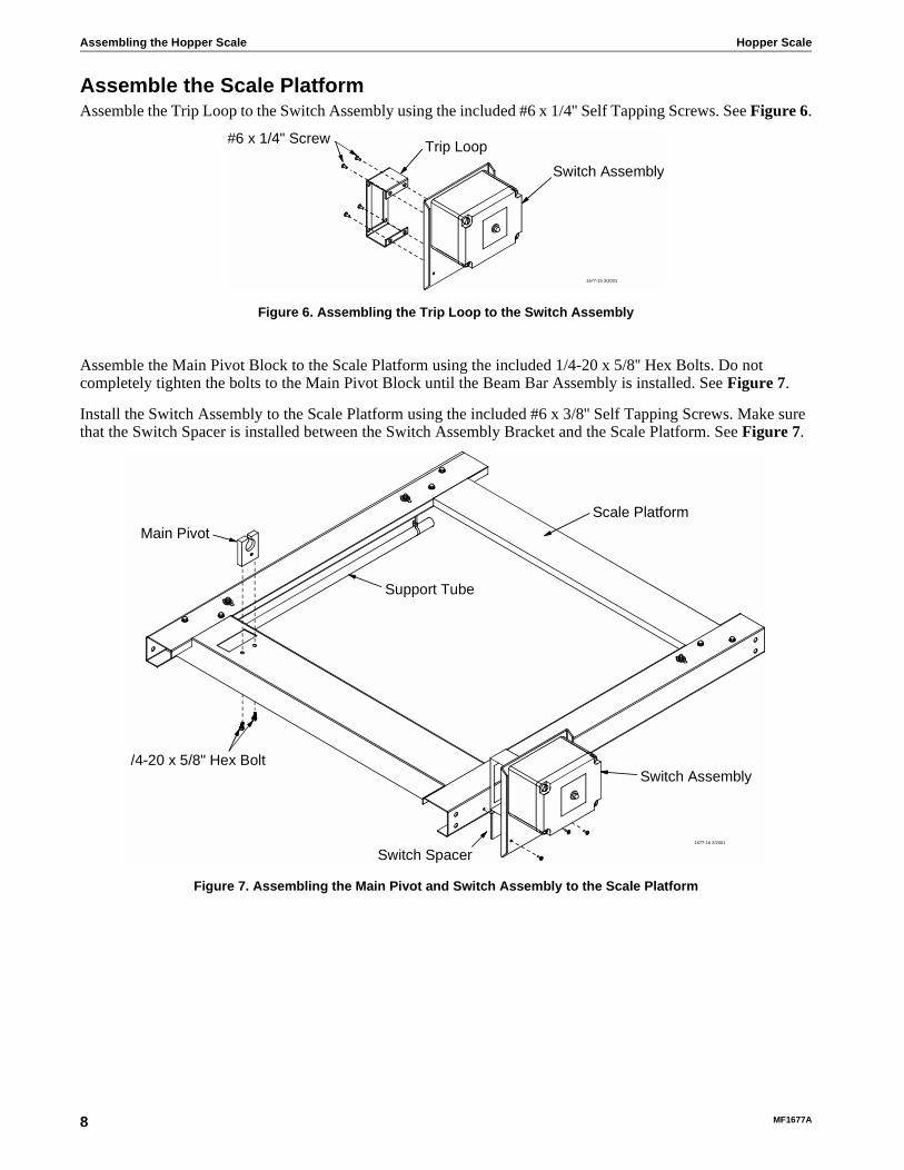
Assemble the Scale PlatformAssemble the Trip Loop to the Switch Assembly using the included #6 x 1/4'' Self Tapping Screws. See Figure 6.
Assemble the Main Pivot Block to the Scale Platform using the included 1/4-20 x 5/8'' Hex Bolts. Do not completely tighten the bolts to the Main Pivot Block until the Beam Bar Assembly is installed. See Figure 7.
Install the Switch Assembly to the Scale Platform using the included #6 x 3/8'' Self Tapping Screws. Make sure that the Switch Spacer is installed between the Switch Assembly Bracket and the Scale Platform. See Figure 7.
Switch Assembly
Trip Loop#6 x 1/4" Screw
1677-15 3/2001
Figure 6. Assembling the Trip Loop to the Switch Assembly
Switch Assembly
Scale PlatformMain Pivot
Support Tube
Switch Spacer
/4-20 x 5/8" Hex Bolt
1677-16 2/2001
Figure 7. Assembling the Main Pivot and Switch Assembly to the Scale Platform
8 MF1677A
Hopper Scale Assembling the Hopper Scale
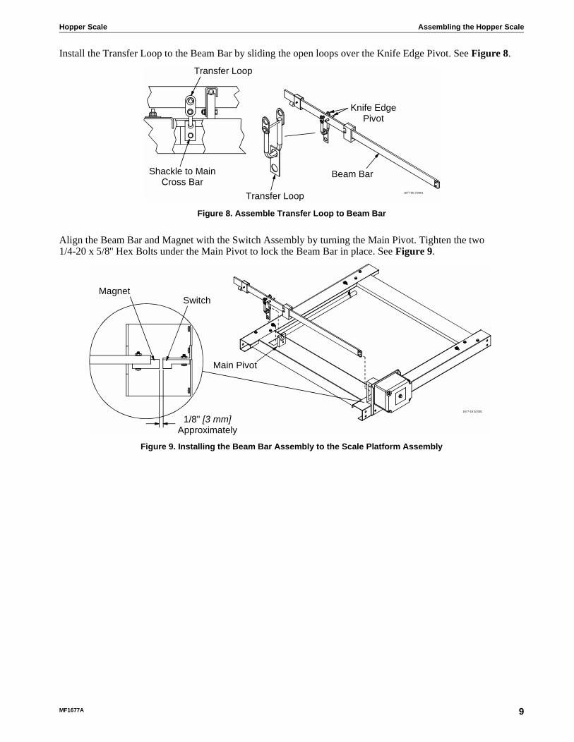
Install the Transfer Loop to the Beam Bar by sliding the open loops over the Knife Edge Pivot. See Figure 8.
Align the Beam Bar and Magnet with the Switch Assembly by turning the Main Pivot. Tighten the two1/4-20 x 5/8'' Hex Bolts under the Main Pivot to lock the Beam Bar in place. See Figure 9.
Shackle to MainCross Bar
Transfer Loop
Beam Bar
Knife EdgePivot
Transfer Loop
1677-50 2/2001
Figure 8. Assemble Transfer Loop to Beam Bar
MagnetSwitch
1/8" [3 mm]Approximately
1677-18 3/2001
Main Pivot
Figure 9. Installing the Beam Bar Assembly to the Scale Platform Assembly
MF1677A 9
Assembling the Hopper Scale Hopper Scale
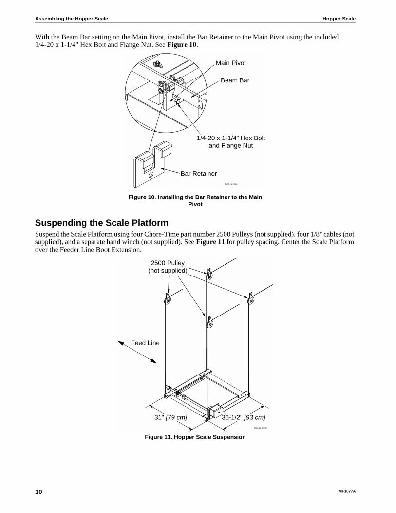
With the Beam Bar setting on the Main Pivot, install the Bar Retainer to the Main Pivot using the included1/4-20 x 1-1/4'' Hex Bolt and Flange Nut. See Figure 10.
Suspending the Scale PlatformSuspend the Scale Platform using four Chore-Time part number 2500 Pulleys (not supplied), four 1/8'' cables (not supplied), and a separate hand winch (not supplied). See Figure 11 for pulley spacing. Center the Scale Platform over the Feeder Line Boot Extension.
Main Pivot
Beam Bar
Bar Retainer
1/4-20 x 1-1/4" Hex Boltand Flange Nut
1677-19 2/2001
Figure 10. Installing the Bar Retainer to the Main Pivot
2500 Pulley(not supplied)
31" [79 cm] 36-1/2" [93 cm]1677-47 3/2001
Feed Line
Figure 11. Hopper Scale Suspension
10 MF1677A

Hopper Scale Assembling the Hopper Scale
Locate the eight Split Bolts (two per cable) and connect the four cables to the Scale Platform. Leave approximately 5' [1.5 m] of cable below the Scale Platform to support the Feeder Line Boot. If using a Twin Feeder Line Boot, the boot must be supported on both sides of the Scale Platform. The hex head of the Split Bolt should be to the inside. Do not completely tighten the Split Bolt until the Scale Platform is leveled.
The Scale Platform must be level. Check all sides of the Scale Platform.
Tighten all Split Bolts.
Assemble the Hopper
300 lb. [136 kg] HopperAssemble the 300 lb. [136 kg] Hopper per instructions. Do not install the hopper hangers. Install 300 lb. [136 kg] Hopper Braces. See Figure 14.
Tighten all hardware.
Split Bolt
Scale Frame Cable
Nut and Washer
1677-21 2/2001
Figure 12. Using the Split Bolts to hang the Scale Platform
Hopper Support
300 lb [136 kg] HopperAdapter Bracket
1677-22 2/2001
Figure 13. Scale Support Brackets
300 lb [136 kg]Hopper Braces
1677-23 3/2001
Figure 14. Installing the 300 lb. [136 kg] Hopper Braces
MF1677A 11

Assembling the Hopper Scale Hopper Scale
Install the 300 lb. [136 kg] Hopper Adapter Brackets (see Figure 15) on the sides where the 300 lb. [136 kg] Hopper Braces are bolted. Position the 300 lb. [136 kg] Hopper Adapter Bracket approximately as shown in Figure 15, mark and drill the three 5/16'' [8 mm] diameter holes. Repeat for the opposite side of the 300 lb. [136 kg] Hopper.
Assemble the 300 lb. [136 kg] Hopper Adapter Bracket (see Figure 15) to the 300 lb. [136 kg] Hopper using the included1/4-20 x 5/8'' Truss Head Screws and Flange Nuts. The Truss Heads should be to the inside of the 300 lb. [136 kg] Hopper.
Install the Hopper Support (see Figure 15) to the 300 lb. [136 kg] Hopper Adapter Bracket (see Figure 15) using the included 1/4-20 x 5/8'' Hex Bolts and Flange Nuts.
Tighten all hardware.
200 lb. [91 kg] HopperAssemble the 200 lb. [91 kg] Hopper per instructions.
Position the Support Bracket approximately as shown in Figure 16, mark and drill three5/16'' [8 mm] diameter holes. Repeat for the opposite side of the 200 lb. [91 kg] Hopper.
Install the Support Bracket (see Figure 16) to the200 lb. [91 kg] Hopper using the included1/4-20 x 5/8'' Truss Head Screws and Flange Nuts. The Truss Heads should be to the inside of the200 lb. [91 kg] Hopper.
Tighten all hardware.
8" [20 cm]
7-1/2" [19 cm]
7-1/2" [19 cm]
1677-24 3/2001
300 lb. [136 kg]Hopper Adapter Bracket
Hopper Support
Figure 15. Installing the Scale Support Brackets
10" [25 cm]
7-1/2" [19 cm]
7-1/2" [19 cm]
11-1/8" [28 cm]
1677-25 2/2001
Hopper Support
Figure 16. Installing the Hopper Support Bracket
12 MF1677A

Hopper Scale Assembling the Hopper Scale
Install the Shut-Off Gate Assembly to the Feed HopperAssemble the Shut-Off Gate Assembly to the Feed Hopper using the included 1/4-20 x 1/2'' Truss Head Screws and Flange Nuts.
Shut-Off Gate Assembly should be located perpendicular to the Feed Tube.
Use two of the Angle Brackets from the Feed Hopper Kit to complete the assembly of the Shut-Off Gate Assembly to the Feed Hopper.
Tighten all hardware.
Feed Hopper
Shut-OffAssembly
Angle Brackets(from hopper hardware)
1677-26 3/2001
Figure 17. Installing the Shut-Off Gate Assembly to the Feed Hopper
MF1677A 13

Assembling the Hopper Scale Hopper Scale
Install Feed Hopper to Scale Platform1. Angle the Feed Hopper in opposite the
Switch Assembly. Hook the Support Bracket over the Support Tube.
2. Lower the other side of the Feed Hopper and hook over the other Support Tube.
When using a 300 lb. [136 kg] Feed Hopper , position the Support Brackets between the center holes of the Support Tube. Slide a 7/8'' [22 mm] Flat Washer next to the Support Bracket and lock with a Hair Pin through the hole in the Support Tube.
Feed Hopper
Switch Assembly
Support Bracket
Support Tube 1677-51 3/2001
Figure 18. Angle the Feed Hopper and hook on Support Tube
Feed Hopper
Switch Assembly
Support Bracket
Support Tube
1677-52 3/2001
Figure 19. Hook other side of the Feed Hopper over the other Support Tube
�������� � ���� ���A DIVISION OF CT BINC.
MI LFORD, INDI ANA 46 542- 2000
������������ �� ����
������
���������
��������
Do not ope n this control box unti l electrical power i s dis conne cted at circuit breakers.
���� ���� �� ��
���� ��
����
����
��
����������
�����
��� ����� �� ���
�� ���� ����� � ���� �� ���
�������� � ���� ���
A DIVISION OF CT BINC.
MI LFORD, INDI ANA 46 542- 2000
������������ �� ����
������
���������
��������
Do not ope n this control box unti l electrical power i s dis conne cted at circuit breakers.
���� ���� �� ��
���� ��
����
����
��
����������
�����
��� ����� �� ���
�� ���� ����� � ���� �� ���
1677-54 3/2001
200 lb [91 kg]Hopper
300 lb [136 kg]Hopper
7/8" [22 mm]Flat Washer
cale Platform
Scale Platform
Support Tube
Support TubeSupport Bracket
Support BracketCable Assembly
Cable Assembly
Hair Pin
Hair Pin
7/8" [22 mm]Flat Washer
Hair Pin
Hair Pin
Figure 18. Installing the Feed Hopper to the Scale Platform
14 MF1677A

Hopper Scale Assembling the Hopper Scale
Zeroing the Hopper ScaleSlide the Poise to zero.
Slide the Counter Weight to level the Beam Bar. Use the Fine Adjust to complete the zeroing process.
Wiring Diagram
Counter Weight
Zero Stop
PoiseFine Adjust
1677-28 2/2001
Figure 19. Zeroing the Hopper Scale
ScaleSwitch
M
30 VACSupply
FLEX-AUGER®Control
Hopper Scale SwitchP/N 46273
1677-29 2/2001
30
33
5
6
3
BLACK
21
43
RED
31
32
31
N/C
65
32
33
N/O
COM
MF1677A 15

Assembling the Hopper Scale Hopper Scale
Figure 20 shows the 300 lb. [136 kg] Feed Hopper setting in the Boot Extension. The Shut-Off Gate should set inside the Boot Extension, but not touch the Boot Extension.
Take the end of one of the Hopper Scale Suspension Cables and run it through the Feed Line Hanger as shown in Figure 20. Bring the other Hopper Scale Suspension Cable down to the first cable and clamp together with a Cable Clamp (not supplied) as shown in Figure 20. If supporting a twin boot, the boot must be supported on both sides.
Hopperssembly
Shut-Off Gate
Boot Extensionwith Switch
Feed Line Boot
Hopper ScaleSuspension Cables
Feed LineHanger
Cable Clamp
1677-48 3/2001
Figure 20. 300 lb. [136 kg] Feed Hopper inside the Boot Extension
16 MF1677A

Hopper Scale Start Up Check List
Check all hardware for tightness. See Figure 21.
Insure that the Scale Platform is level. See Figure 22.
Check cables for straightness, horizontal and vertical. Cables must hang straight. The Cable can be adjusted by sliding along the Support Tube as necessary and by loosening the Cable Adjustment Nut and moving the Cable as necessary. See Figure 23.
Check Support Tube for Hair Pins and Washers.See Figure 24.
Check Scale for ease of movement.
Start Up Check List
1677-32 2/2001
Figure 21. Check Hardware
1677-33 2/2001
Figure 22. Check Scale Platform
1677-34 3/2001
Cables musthang straight
Scale Platform
Cable Adjustment Nut
Scale Platform
Cable Adjustment Nut
Support Tube
Figure 23. Check Cables for Straightness
Support BarHair Pin
Cable AssemblyFlat WasherSupport Tube 1677-35 2/2001
Figure 24. Check Hair Pins and Washers
MF1677A 17

Operating the Hopper Scale Assembly Hopper Scale
All Shackles should hang straight. See Figure 25.
Check alignment of Magnet on the Beam Bar and the Switch Assembly. See Figure 26.
With the Hopper Scale Assembly balanced, slide the Poise to the desired weight. See Figure 27.
Close the Shut-Off Gate on the bottom of the Feed Hopper. See Figure 28.
Operating the Hopper Scale Assembly
1677-36 2/2001
Figure 25. Check all Shackles
Beam Bar
MagnetScale Switch
1677-37 2/2001
Figure 26. Check Magnet Alignment
Counter Weight
Beam Bar
Poise
1677-38 2/2001
Figure 27. Balance Hopper Scale Assembly
Shut-OffAssembly
1677-40 2/2001
Figure 28. Close the Shut-Off Gate
18 MF1677A

Hopper Scale Parts Listing
Push the Push Button on the front of the Hopper Scale Switch Box. The FLEX-AUGER® System should run until the desired weight has been reached. See Figure 29.
Open the Shut-Off Gate to allow feed to flow into the Feeder Boot. See Figure 28.
Switch Assembly Part Number 46273
Parts Listing
Item Description Part No. Item Description Part No.1 Scale Control Spacer 46256 7 3/8'' Liquid Tight Connector 134772 Trip Loop 46273 8 Terminal Block 34925-33 Scale Switch Bracket 46246 9 Push Button Switch 57854 Reed Switch 6689 10 4 x 6 Box Screw (Plastic) 428495 Scale Control Mount Panel 46271 11 Push Button Boot 207846 General Duty Relay 28904
Switch Box
Push Button1677-39 2/2001
Figure 29. Start the FLEX-AUGER® System
��������� ���� ���
A DIVISION OF CTB INC.
MILFORD, INDIANA 46542-2000
�������������� ����
������
������ ���
��������
Do not open this control box until electrical power is disconnected at circuit breakers.
���� ���� �� ��
���� ��
����
HOPPER
FILL
����������
�����
��� ����� �� ���
������ ����� � ���� �� ���
1677-41 2/2001
3 4
1
2
10
8
9
6 7
5
11
MF1677A 19

Parts Listing Hopper Scale
Hanging Scale Part Number 46280
Beam Bar Assembly Part Number 46279
Item Description Part No. Item Description Part No.1 Transfer Loop 46243 11 Hopper Support Adapter 462502 Beam Bar Assembly 46279 12 3/8'' Hex Nut 15493 Bar Retainer 46257 13 3/8'' Flat Washer 49674 Support Tube 46270 14 3/8'' Split Bolt 63425 Scale End Frame 46248 15 Hair Pin 139066 Scale Side Frame 46247 16 Bar Pivot Bearing (short) 462637 Hair Pin 2664 17 Pivot Shackle 462548 7/8'' Flat Washer 2955-14 18 Main Pivot Block 462659 Switch Assembly 46273 — Bar Pivot Bearing (long) 4626410 Support Bar 46251
2
1
3
4
5
6
7
9
8
121314
16
17
18
1677-42 3/2001
10
11
15
1 24 53
1677-45 2/2001
Item Description Part No.1 Counter Weight Assembly 462612 Poise Assembly 462683 Beam Bar Decal 2529-4014 Machined Beam Bar 462495 Actuator Magnet 5789
20 MF1677A

Hopper Scale Parts Listing
Shut-Off Gate Assembly Part Number 46226
Item Description Part No.1 #10-24 Hex Lock Nut2 Shut-Off Side Panel 462333 Shut-Off Spacer 462284 Hopper Angle
200 lb. [91 kg]300 lb. [136 kg]
4623046231
5 #10-24 x 5/8'' Hex Washer Head Screw 18766 Shut-Off Gate 462297 #10-24 x 5/8'' Truss Head Screw 501A8 Shut-Off End Panel 462329 Boot Extension Side Panel 4623410 Boot Extension Side Panel with Switch Hole 46235
1677-43 2/2001
6 9
108
7
1
3
2
4
5
7
1
MF1677A 21

Parts Listing Hopper Scale
Lower Hopper Switch Assembly Part Number 8798
Item Description Part No.1 Mounting Plate 79082 #10-32 Hex Nut 42973 Switch Box 78414 Gasket 67775 #10 Twin Helix Screw 69806 #6 x 3/8" Self Tapping Screw 460117 Switch Bracket 70688 #6-32 Hex Nut 7719 Switch Insulation 1907-510 Switch Box Cover 677611 SPDT Actuator Switch 4609112 #6-32 x 7/8" Round Head Machine Screw 192113 Pin 875714 10-32 Hex Lock Nut 696315 Spring 697216 Gasket 6968-117 Paddle 789618 Diaphragm Assembly 7900-- Deflector 28281
1677-55 3/2001
18
17
34
2 1
1610
5
6
7
8
9
11
12 13 1415
22 MF1677A

Hopper Scale Parts Listing
This page intentionally left blank
MF1677A 23

Made to work.Built to last.
Revisions to this Manual
Page No. Description of Change
Contact your nearby Chore-Time distributor or representative for additional parts and information.
CTB Inc.P.O. Box 2000 • Milford, Indiana 46542-2000 • U.S.A.
Phone (219) 658-4101 • Fax (877) 730-8825E-Mail: [email protected] • Internet: http//www.ctbinc.com
Printed in the U.S.A.
MF1677A