horizontal slide-valve engine -...
TRANSCRIPT

HORIZONTAL SLIDE-VALVE ENGINE
The engine illustrated in Figs. 53 to 66 willgive sufficient scope for energy and handi-ness with drill and soldering iron. The writermade an engine of the same kind, differingonly from that shown in the design of thecross head guides, without the assistanceof a lathe, except for turning the piston andfly wheel -- the last bought in the rough.Files, drills, taps, a hack saw, and asoldering iron did all the rest of the work.
Solder plays so important a part in theassembling of the many pieces of theengine that, if the machine fell into the fire,a rapid disintegration would follow. But inactual use the engine has proved verysatisfactory; and if not such as the highly-skilled model-maker with a well-equippedworkshop at his command would prefer toexpend his time on, it will afford a usefullesson in the use of the simpler tools. Under50 lbs. of steam it develops sufficient powerto run a small electric-lighting installation,or to do other useful work on a moderatescale.
The principal dimensions of the engine areas follows;
1. Bedplate (sheet zinc), 13-1/2 incheslong; 4-1/2 inches wide; 1/8 inch thick.
2. Support of bedplate (1/20 inch zinc), 3inches high from wooden base tounderside of bedplate.
3. Cylinder (mandrel-drawn brass tubing),1-1/2 inches internal diameter; 2-13/16inches long over all.
4. Piston, 1-1/2 inches diameter; 1/2 inchlong.
5. Stroke of piston, 2-1/4 inches. 6. Connecting rod, 5 inches long between
centers; 7. 5/16 inch diameter. 8. Piston rod, 5-1/8 inches long; 1/4 inch
diameter. 9. Valve rod, 4-1/8 inches long; 3/16 inch
diameter. 10.Crank shaft, 5 inches long; 1/2 inch
diameter. 11.Center line of piston rod, 1-1/4 inches
laterally from near edge of bed; 1-5/8inches from valve-rod center line; 1-5/8inches vertically above bed.
12.Center line of crank shaft, 10-3/8 inchesfrom cross center line of cylinder.
13.Bearings, 1 inch long. 14.Eccentric, 9/32-inch throw. 15.Fly wheel, diameter, 7-1/2 inches;
width, 1 inch; weight, 6 lbs. 16.Pump, 3/8-inch bore; 3/8-inch stroke;
plunger, 2 inches long.
Page 1

HORIZONTAL SLIDE-VALVE ENGINE
Page 2

HORIZONTAL SLIDE-VALVE ENGINE
Page 3
HORIZONTAL SLIDE-VALVE ENGINE
Other dimensions will be gathered from thevarious diagrams of details. The readerwill, of course, suit his own fancy infollowing these dimensions, or in working tothem on a reduced scale, or in modifyingdetails where he considers he can effect hisobject in a simpler manner.
The diagrams are sufficiently explicit to renderit unnecessary to describe the making of theengine from start to finish, so remarks will belimited to those points which require mostcareful construction and adjustment.
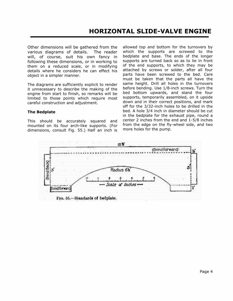
The Bedplate
This should be accurately squared andmounted on its four arch-like supports. (Fordimensions, consult Fig. 55.) Half an inch is
allowed top and bottom for the turnovers bywhich the supports are screwed to thebedplate and base. The ends of the longersupports are turned back so as to lie in frontof the end supports, to which they may beattached by screws or solder, after all fourparts have been screwed to the bed. Caremust be taken that the parts all have thesame height. Drill all holes in the turnoversbefore bending. Use 1/8-inch screws. Turn thebed bottom upwards, and stand the foursupports, temporarily assembled, on it upsidedown and in their correct positions, and markoff for the 3/32-inch holes to be drilled in thebed. A hole 3/4 inch in diameter should be cutin the bedplate for the exhaust pipe, round acenter 2 inches from the end and 1-5/8 inchesfrom the edge on the fly-wheel side, and twomore holes for the pump.
Page 4
HORIZONTAL SLIDE-VALVE ENGINE
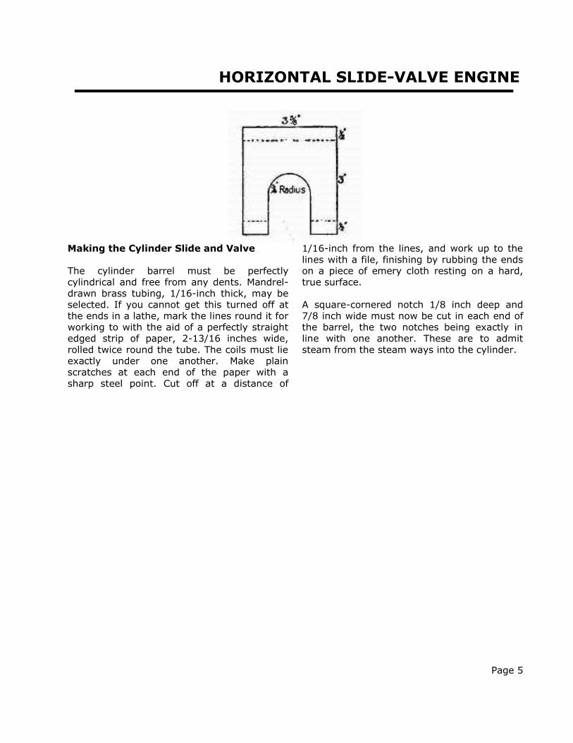
Making the Cylinder Slide and Valve
The cylinder barrel must be perfectlycylindrical and free from any dents. Mandrel-drawn brass tubing, 1/16-inch thick, may beselected. If you cannot get this turned off atthe ends in a lathe, mark the lines round it forworking to with the aid of a perfectly straightedged strip of paper, 2-13/16 inches wide,rolled twice round the tube. The coils must lieexactly under one another. Make plainscratches at each end of the paper with asharp steel point. Cut off at a distance of
1/16-inch from the lines, and work up to thelines with a file, finishing by rubbing the endson a piece of emery cloth resting on a hard,true surface.
A square-cornered notch 1/8 inch deep and7/8 inch wide must now be cut in each end ofthe barrel, the two notches being exactly inline with one another. These are to admitsteam from the steam ways into the cylinder.
Page 5

HORIZONTAL SLIDE-VALVE ENGINE
Cylinder Standards
Use 5/64 or 3/32 inch brass plate for these.Two pieces of the dimensions shown in Fig. 56are needed. Scratch a line exactly down themiddle of each, and a cross line 1/2 inch fromone end. The other end should be marked,cut, and filed to a semicircle. Drill three 3/16-inch holes in the turnover for the holding-down screws. The two standards should nowbe soldered temporarily together at the roundends and trued up to match each otherexactly. Place them in the vice with thebending lines exactly level with the jaws, splitthe turnovers apart, and hammer them overat right angles to the main parts. Whether thishas been done correctly may be tested byplacing the standards on a flat surface. Takethe standards apart, and scratch a cross line
on each 1-5/8 inch from the lower surface ofthe foot on the side away from the foot. Makea punch mark where the line crosses thevertical line previously drawn, and with this ascenter describe a circle of the diameter of theoutside of the barrel. Cut out the inside andfile carefully up to the circle, stopping whenthe barrel makes a tight fit. On the inside ofthe hole file a nick 1/8 inch deep, as shown inFig. 56. Remember that this nick must be onthe left of one standard and on the right of theother, so that they shall pair off properly.
Standards and barrel must now be cleaned forsoldering. Screw one standard down to a woodbase; slip one end of the barrel into it; passthe other standard over the other end of thebarrel, and adjust everything so that thebarrel ends are flush with the, outer surfaces
Page 6

HORIZONTAL SLIDE-VALVE ENGINE
of the standard, and the nicks of the barrel inline with the standard nicks. Then screw theother standard to the base. Solder must berun well into the joints, as these will have tostand all the longitudinal working strain.
The next step is the fitting of the cylindercovers. If you can obtain two stout brass discs2-1/8 inches in diameter, some trouble will besaved; otherwise you must cut them out of3/32-inch plate. The center of each should bemarked, and four lines 45 degrees apart bescratched through it from side to side. A circleof 15/16-inch radius is now drawn to cut thelines, and punch marks are made at the eightpoints of intersection. Solder the covers lightlyto the foot side of their standards, markedsides outwards, and drill 1/8-inch holesthrough cover and standard at the punchmarks. Make matching marks on the edges.Unsolder the covers, enlarge the holes in themto take 5/32-inch screws; and tap the holes inthe standards. This method will ensure theholes being in line, besides avoiding thetrouble of marking off the standardsseparately.
Bore a 1/4-inch hole in the center of onecover--be sure that it is the right one--for thepiston rod.
You can now proceed to the making of thepiston-rod gland (Fig. 54, G1). Fig. 57 showshow this is built up of pieces of tubing andbrass lugs for the screws. If possible, get thetubular parts trued in a lathe.
Before the gland is soldered to the cover, thecover should be put in place, the piston rodattached to the piston, and the parts of thegland assembled. Push the piston rod throughthe cover until the piston is hard up againstthe back of the cover. Slip the gland over therod, turn it so that the screws are parallel tothe foot of the standard, and make the solderjoint. This is the best way of getting the glandexactly concentric with the cylinder so that thepiston rod shall move without undue friction.But you must be careful not to unsolder thecylinder from its standard or the parts of thegland. Blacken the piston rod in a candleflame to prevent solder adhering.
Page 7

HORIZONTAL SLIDE-VALVE ENGINE
Steam Chest
The walls of the steam chest are best made inone piece out of 1/2-inch brass by cutting outto the dimension given in Fig. 58. A sharp fretsaw will remove the inside rectangle. Get bothinside and outside surfaces as square aspossible in all directions, and rub down thetwo contact faces on emery cloth supported byan old looking-glass.
Two perfectly flat plates of 1/8-inch brass arecut to the size given in Fig. 59, or a littlelonger both ways, to allow for working downto the same area as the wall-piece. Thisoperation should be carried out after solderingthe three pieces together. File and rub thesides until no projections are visible. Then drill
twelve 3/32-inch holes right through the threeparts. After separating them, the holes in thewalls and what will be the cover must beenlarged to an easy fit for 1/8-inch bolts, andthe valve plate tapped.
Now drill 3/16-inch holes centrally through theends of the walls for the valve rod. If the firsthole is drilled accurately, the second holeshould be made without removing the drill, asthis will ensure the two holes being in line. If,however, luck is against you, enlarge theholes and get the rod into its correct positionby screwing and soldering small drilled platesto the outside of the chest. Also drill and tap ahole for the lubricator. The attachment of thegland (Fig. 54, G2) is similar to that of thecylinder gland, and therefore need not bedetailed.
Page 8

HORIZONTAL SLIDE-VALVE ENGINE
Page 9

HORIZONTAL SLIDE-VALVE ENGINE
The Valve Plate (Fig. 59)
Three ports must be cut in this--a central one,7/8 by 3/32 inch, for the exhaust; and twoinlets, 7/8 by 3/32 inch, 1/8 inch away fromthe exhaust. These are easily opened out if aseries of holes be drilled along their axes.
The Steam Ways
The formation of the steam ways betweenvalve plate and cylinder is the most ticklish bitof work to be done on the engine as it entailsthe making of a number of solder joints closetogether.
We begin by cutting out of 1/20-inch sheetbrass a piece shaped as in Fig. 60. Parallel tothe long edges, and 3/8 inch away, scribebending lines. Join these by lines 5/8 inchfrom the short edges, and join these again bylines 1/4 inch from the bending lines. Cutsmust now be made along the lines showndouble in Fig. 60. Bend parts CC down andparts BB upwards, so that they are at rightangles to parts AA. The positions of theseparts, when the piece is applied to thecylinder, are shown in Fig. 62.
One must now make the bridge pieces (Fig.61, a, a) to separate the inlet passages fromthe exhaust. Their width is the distancebetween the bent-down pieces CC of Fig. 60,and their bottom edges are shaped to thecurvature of the cylinder barrel. Finally, make
the pieces bb (Fig. 61), which form part of thetop of the steam ways.
In the assembling of these parts a blowpipespirit lamp or a little "Tinol" soldering lampwill prove very helpful.
The following order should be observed:
(1.) Solder the piece shown in Fig. 60 to thecylinder barrel by the long edges, and to thecylinder supports at the ends. This piecemust, of course, cover the steam ports in thecylinder.
(2.) Put pieces aa (Fig. 61) in position, withtheir tops quite flush with the tops of BB (Fig.62), and solder them to the cylinder barreland sides of the steam-way piece.
Page 10

HORIZONTAL SLIDE-VALVE ENGINE
Page 11

HORIZONTAL SLIDE-VALVE ENGINE
(3.) Solder the valve plate centrally to BB, andto the tops of aa, which must lie between thecentral and outside ports. Take great care tomake steam-tight joints here, and to have theplate parallel to the standards in one directionand to the cylinder in the other.
(4.) Solder in pieces bb. These should be atight fit, as it is difficult to hold them in placewhile soldering is done.
(5.) Bore a 5/16-inch hole in the lower side ofthe central division and solder on the exhaustpipe.
Page 12

HORIZONTAL SLIDE-VALVE ENGINE
The Crank and Crank Shaft
The next thing to take in hand is the fixing ofthe crank shaft. This is a piece of 3/8 or 1/2inch steel rod 5 inches long.
The bearings for this may be pieces of brasstubing, fitting the rod fairly tight. By makingthem of good length--1 inch--the wear isreduced to almost nothing if the lubricatingcan is used as often as it should be. Each bearing is shown with two standards.The doubling increases rigidity, and enablesan oil cup to be fixed centrally.
The shape of the standards will be gatheredfrom Fig. 53, their outline being dotted inbehind the crank.
Cut out and bend the standards--after drillingthe holes for the foot screws--beforemeasuring off for the centers of the holes; infact, follow the course laid down with regardto the cylinder standards.
Make a bold scratch across the bedplate toshow where the center line of the shaft shouldbe, and another along the bed for the piston-rod center line. (Position given on p. 138.)
Bore holes in the bearings for the oil cups,which may be merely forced in after theengine is complete.
The crank boss may be made out of a brassdisc 2-3/4 inches diameter and 3/16 inchthick, from which two curved pieces are cut toreduce the crank to the shape shown in Fig.53. The heavier portion, on the side of theshaft away from the crank pin, helps tocounterbalance the weight of the connectingand piston rods. In Fig. 54 (plan of engine)you will see that extra weight in this part hasbeen obtained by fixing a piece of suitablycurved metal to the back of the boss.
The mounting of the crank boss on the shaftand the insertion of the crank pin into theboss might well be entrusted to an expert
mechanic, as absolute "squareness" isessential for satisfactory working. Screw-thread attachments should be used, and thecrank-shaft should project sufficiently to allowroom for a flat lock nut. The crank pin will berendered immovable by a small lock screwpenetrating the boss edge ways and engagingwith a nick in the pin.
Fixing the Standards and Bearings
Place the two bearings in their standards andslip the crank shaft through them. Placestandards on the bed, with their center lineson the crank-shaft center line. The face of thecrank should be about 3/8 inch away from thepiston rod center line. Bring the nearerbearing up against the back of the disc, andarrange the standards equidistantly from theends of the bearing. The other bearing shouldoverlap the edge of the bed by about 1/8 inch.Get all standards square to the edge of thebed, and mark off the positions of screw holesin bed. Remove the standards, drill and tapthe bed-plate holes, and replace parts asbefore, taking care that the lubricating holesin the bearings point vertically upwards. Thensolder bearings to standards. If any difficulty is experienced in getting allfour standards to bed properly, make thebearing holes in the two inner ones a rathereasy fit. The presence of the crank-shaft willassure the bearings being in line when thesoldering is completed. The standards and bed should have matchingmarks made on them.
The Eccentric
This can be formed by soldering two thinbrass discs 1-15/16- inch diameterconcentrically to the sides of a disc of 1-15/16-inch diameter and 5/16 inch thick. Thecenter of the shaft hole must be exactly 9/32inch from the center of the eccentric to give
Page 13

HORIZONTAL SLIDE-VALVE ENGINE
the proper valve-travel. Drill and tap theeccentric edge ways for a lock screw.
A piece to which the eccentric strap, eccentricrod, and pump rod are attached is cut out of5/16-inch brass. Its shape is indicated inFigure 53. The side next the eccentric must beshaped as accurately as possible to the radiusof the eccentric. The strap, of strip brass, isfastened to the piece by four screws, theeccentric rod by two screws.
Crosshead and Guides
The crosshead (Figs. 53 and 54) is built up bysoldering together a flat foot of steel, a brassupright, and a tubular top fitting the pistonrod. The guides, which consist of a bed,
covers, and distance-pieces united by screws(Fig. 64), have to withstand a lot of wear, andshould preferably be of steel. The importanceof having them quite flat and straight is, ofcourse, obvious.
The last 1-3/8 inches of the piston rod has ascrew thread cut on it to engage with athreaded hole in the fork (cut out of thickbrass plate), to which the rear end of theconnecting rod is pinned, and to take the locknut which presses the crosshead against thisfork.
Assuming that all the parts mentioned havebeen prepared, the cylinder should bearranged in its proper place on the bed, thepiston rod centrally over its center line. Markand drill the screw holes in the bed.
Page 14

HORIZONTAL SLIDE-VALVE ENGINE
The Valve Gear. -- We may now attend tothe valve gear. A fork must be made for theend of the valve rod, and soldered to it withits slot at right angles to the slots whichengage with the valve lugs. Slip the rod intothe steam chest, put the valve on the rod, andattach the chest (without the cover) to thevalve plate by a bolt at each corner. Pull thevalve forward till the rear port is justuncovered, and turn the eccentric full forward.You will now be able to measure off exactlythe distance between the centers of the valve-rod fork pin and the rear screw of theeccentric. The valve connecting rod (Fig. 53,VCR) should now be made and placed inposition. If the two forward holes are filedsomewhat slot-shaped, any necessaryadjustment of the valve is made easier. If theadjustment of VCR and the throw of theeccentric are correct, the valve will justexpose both end ports alternately when thecrank is revolved. If one port is more exposedthan the other, adjust by means of theeccentric screws till a balance is obtained.Should the ports still not be fully uncovered,the throw of the eccentric is too small, andyou must either make a new eccentric orreduce the width of the valve. (The secondcourse has the disadvantage of reducing theexpansive working of the steam.) Excessmovement, on the other hand, implies toogreat an eccentric throw.
Setting the Eccentric
Turn the crank full forward, so that a linethrough the crank pin and shaft centers isparallel to the bed. Holding it in this position,revolve the eccentric (the screw of whichshould be slackened off sufficiently to allowthe eccentric to move stiffly) round the shaftin a clockwise direction, until it is in thatposition below the shaft at which the frontsteam port just begins to show. Then tighten
up the eccentric lock screw.1
The Connecting Rod. -- The length of thisfrom center to center of the pins on which itworks should be established as follows:--Slipover the piston rod a disc of card 1/32 inchthick. Then pass the rod through the glandand assemble the crosshead and fork on itsend, and assemble the guides round thecrosshead foot. Turn the crank pin fullforward, pull the piston rod out as far as it willcome, measure the distance between pincenters very carefully, and transfer it to apiece of paper.
The rod consists of a straight central bar andtwo rectangular halved ends. The ends shouldbe cut out of brass and carefully squared.Through their exact centers drill 1/8-inchholes, and cut the pieces squarely in twoacross these holes. The sawed faces should befiled down to a good fit and soldered together.Now drill holes of the size of the pins, usingwhat remains of the holes first made to guidethe drill. The bolt holes are drilled next, andfinally the holes for lubrication and those totake the rods. Then lay the two ends down onthe piece of paper, so that their pinholes arecentered on the center marks, and the holesfor the rod are turned towards one another.Cut off a piece of steel rod of the properlength and unsolder the ends. The rod piecesmust then be assembled on the rod, and withit be centered on the paper and held inposition while the parts are soldered together.
OTHER DETAILS
Adjusting the Guides
Put the connecting rod in place on its pins,and revolve the crank until the guides have
1 The reader is referred to an excellent little treatise,entitled "The Slide Valve" (Messrs. Percival Marshalland Co., 26 Poppin's Court, Fleet Street, E.C. Price6d.), for a full explanation of the scientific principlesof the slide valve.]
Page 15

HORIZONTAL SLIDE-VALVE ENGINE
taken up that position which allows thecrosshead to move freely. Then mark off theholes for the guide holding-down screws, anddrill and tap them.
Packings
.The glands and piston should be packed withasbestos string. Don't be afraid of packing tootightly, as the tendency is for packing to getslacker in use. The rear end of the cylindershould be beveled off slightly inside, to allowthe packed piston to enter easily.
Joints
The cylinder head and valve chest jointsshould be made with stout brown papersoaked in oil or smeared with red lead. Allscrew holes should be cut cleanly through thepaper, and give plenty of room for the screws.
When making a joint, tighten up the screws inrotation, a little at a time so as not to putundue strain on any screw. Wait an hour ortwo, and go round with the screw-driveragain.
Page 16

HORIZONTAL SLIDE-VALVE ENGINE
Lubrication
When the engine is first put under steam,lubrication should be very liberal, to assurethe parts "settling down" without undue wear.
The Pump
Figure 65 shows in section the pump, whichwill be found a useful addition to the engine.(For other details, see Figs. 53 and 54.) Itsstroke is only that of the eccentric, and as thewater passages and valves are of good size, itwill work efficiently at high speed. The methodof making it will be obvious from thediagrams, and space will therefore not bedevoted to a detailed description. The valveballs should, of course, be of gun-metal orbrass, and the seatings must be prepared forthem by hammering in a steel ball of thesame size.
In practice it is advisable to keep the pumpalways working, and to regulate the deliveryto the boiler by means of a by-pass tap on thefeed pipe, through which all or some of thewater may be returned direct to the tank.
The tank, which should be of zinc, mayconveniently be placed under the engine. Ifthe exhaust steam pipe be made to traversethe tank along or near the bottom, a gooddeal of what would otherwise be wasted heatwill be saved by warming the feed water.
Making a Governor
It is a great advantage to have the engineautomatically governed, so that it may run ata fairly constant speed under varying loadsand boiler pressures.
In the absence of a governor one has to beconstantly working the throttle; with onefitted, the throttle can be opened up full at thestart, and the automatic control relied upon toprevent the engine knocking itself to pieces.
The vertical centrifugal apparatus shown inFig. 66 was made by the writer, and acted
very well. The only objection to it is itsdisplacement of the pump from the bed. But alittle ingenuity will enable the pump to bedriven off the fly wheel end of the crank shaft,or, if the shaft is cut off pretty flush with thepulley, off a pin in the face of the pulley.
Turning to Fig. 66, A is a steel spindle fixedin a base, L, screwed to the bed. B is a brasstube fitting A closely, and resting at thebottom on a 1/4-inch piece of similar tubingpinned to A.
A wooden pulley jammed on B transmitsthe drive from a belt which passes at its otherend round a similar, but slightly larger, pulleyon the crank shaft. This pulley isaccommodated by moving the eccentricslightly nearer the crank and shortening thefly-wheel side bearing a little.
The piece G, fixed to B by a lock screw, hastwo slots cut in it to take the upper ends ofthe weight links DD; and C, which slides upand down B, is similarly slotted for the linksEE. Each of the last is made of two similarlyshaped plates of thin brass, soldered togetherfor half their length, but separated 3/32 inchat the top to embrace the projections of D. Toprevent C revolving relatively to B, a notch isfiled in one side of the central hole, to engagewith a piece of brass wire soldered on B(shown solid black in the diagram). A spiralsteel spring, indicated in section by a numberof black dots, presses at the top against theadjustable collar F, and at the bottom againstC.
The two weights WW are pieces of brass barslotted for driving on to DD, which tapergently towards the outer edge.
When the pulley revolves, centrifugal forcemakes WW fly outwards against the pressureof the spring, and the links EE raise C, whichin turn lifts the end of lever M. A single link,N, transmits the motion from a pin on M tothe double bell-crank lever O (see Fig. 66)
Page 17

HORIZONTAL SLIDE-VALVE ENGINE
pivoted on a standard, P, attached to thebedplate. The slotted upper ends of P engagewith pins on an adjustable block, R, whichmoves the governing valve V (solid black),working in the tube S through a gland. Thehigher M is raised the farther back is Vmoved, and its annular port is graduallypushed more out of line with two ports in theside of the valve tube, thus reducing the flowof steam from the supply pipe to the cylinder
connection on the other side of the tube. Thisconnection, by-the-bye, acts as fulcrum forlever M, which is made in two parts, heldtogether by screws, to render detachmenteasy.
The closer the fit that V makes with S themore effective will the governing be. Thegland at the end of S was taken from an oldcylinder cover.
Page 18

HORIZONTAL SLIDE-VALVE ENGINE
Regulation of the speed may be effectedeither
(1) by driving the governor faster or slowerrelatively to the speed of the crankshaft;
(2) by altering the position of W on D;
(3) by altering the compression of thespring by shifting F;
(4) by a combination of two or more of theabove.
Generally speaking, (3) is to be preferred, asthe simplest.
The belt may be made out of a bootlace orfairly stout circular elastic. In either case theends should be chamfered off to form asmooth joint, which may be wrappedexternally with thread.
FINAL HINTS
All parts which have to be fitted togethershould have matching marks made on themwith the punch. To take the parts of the valvechest as an example. As we have seen, theseshould be soldered together, finished off
outside, and drilled. Before separating themmake, say, two punch marks on what will bethe upper edge of the valve plate near theend, and two similar marks on the chest asnear the first as they can conveniently be. Inlike manner mark the chest cover and anadjacent part of the chest with three marks. Itis utterly impossible to reassemble the partsincorrectly after separation if the marks arematched. Marking is of greatest importancewhere one piece is held up to another by anumber of screws. If it is omitted in such acase, you may have a lot of trouble inmatching the holes afterwards.
Jacket the cylinder with wood or asbestos,covered in neatly with sheet brass, tominimize condensation. If the steam ways,valve chest, and steam pipe also are jacketed,an increase in efficiency will be gained,though perhaps somewhat at the expense ofappearance.
Boiler
A vertical multi tubular boiler with about 800sq. inches of heating surface will drive thisengine satisfactorily.
The Project Gutenberg EBook of Things To Make, by Archibald Williams
This project is for the use of anyone anywhere at no cost and withalmost no restrictions whatsoever. You may copy it, give it away orre-use it under the terms of the Project Gutenberg License included
with this eBook or on line at www.gutenberg.net
Transcribed by David Lee ~ [email protected]
Page 19