hose-diaphragm pumps - delta pompen b.v. · and water technology, such as burner equip- ... ensures...
TRANSCRIPT
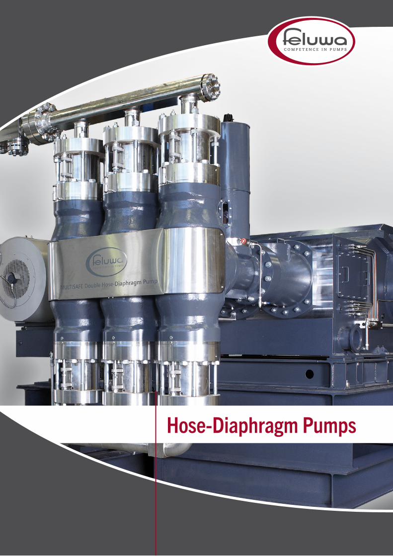
Hose-Diaphragm Pumps
FELUWA Pumpen GmbH has at its base in excess of 100 years’ corporate his-
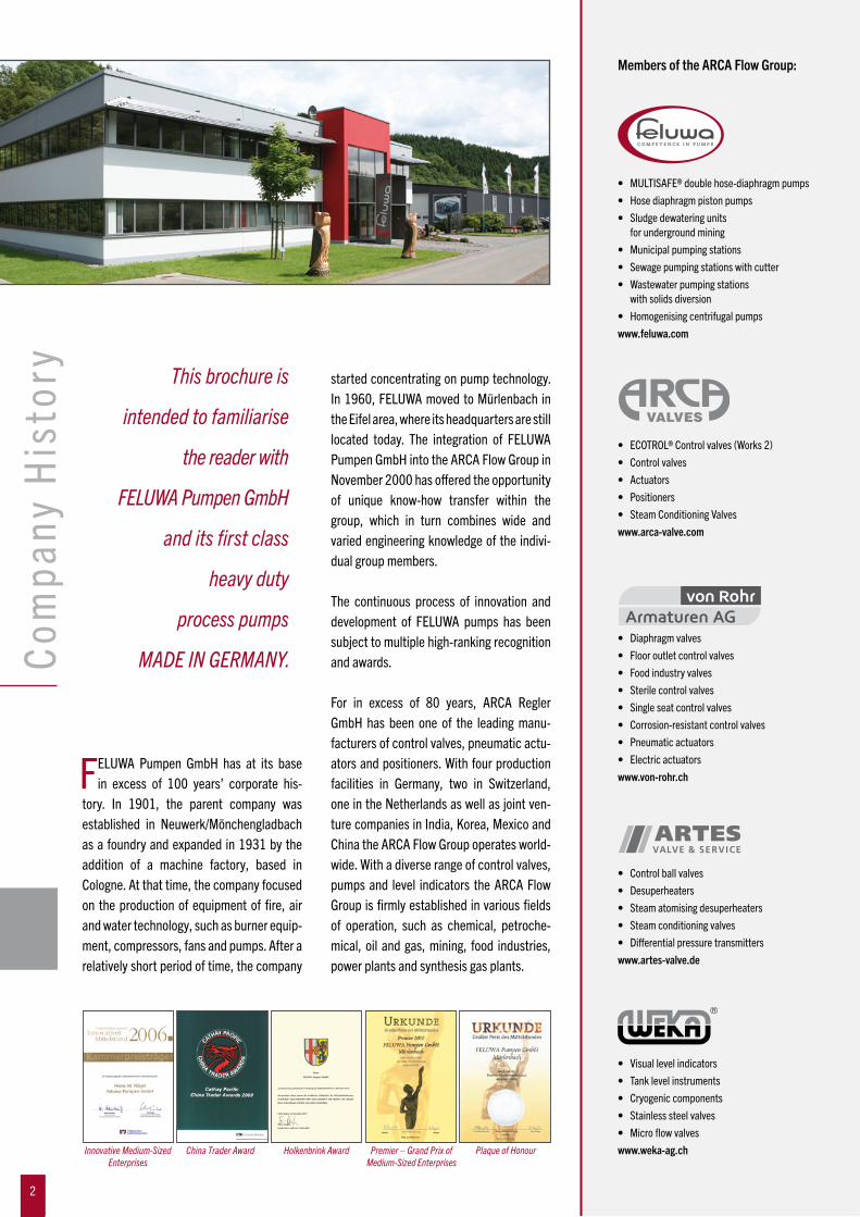
tory. In 1901, the parent company was established in Neuwerk/Mönchengladbach as a foundry and expanded in 1931 by the addition of a machine factory, based in Cologne. At that time, the company focused on the production of equipment of fire, air and water technology, such as burner equip-ment, compressors, fans and pumps. After a relatively short period of time, the company
started concentrating on pump technology. In 1960, FELUWA moved to Mürlenbach in the Eifel area, where its headquarters are still located today. The integration of FELUWA Pumpen GmbH into the ARCA Flow Group in November 2000 has offered the opportunity of unique know-how transfer within the group, which in turn combines wide and varied engineering knowledge of the indivi-dual group members.
The continuous process of innovation and development of FELUWA pumps has been subject to multiple high-ranking recognition and awards.
For in excess of 80 years, ARCA Regler GmbH has been one of the leading manu-facturers of control valves, pneumatic actu-ators and positioners. With four production facilities in Germany, two in Switzerland, one in the Netherlands as well as joint ven-ture companies in India, Korea, Mexico and China the ARCA Flow Group operates world-wide. With a diverse range of control valves, pumps and level indicators the ARCA Flow Group is firmly established in various fields of operation, such as chemical, petroche-mical, oil and gas, mining, food industries, power plants and synthesis gas plants.
Com
pany
His
tory This brochure is
intended to familiarise
the reader with
FELUWA Pumpen GmbH
and its first class
heavy duty
process pumps
MADE IN GERMANY.
Members of the ARCA Flow Group:
• Diaphragmvalves• Flooroutletcontrolvalves• Foodindustryvalves• Sterilecontrolvalves• Singleseatcontrolvalves• Corrosion-resistantcontrolvalves• Pneumaticactuators• Electricactuatorswww.von-rohr.ch
• MULTISAFE®doublehose-diaphragm pumps• Hosediaphragmpistonpumps• Sludgedewateringunits for underground mining• Municipalpumpingstations• Sewagepumpingstationswithcutter• Wastewaterpumpingstations with solids diversion• Homogenisingcentrifugalpumpswww.feluwa.com
• Controlballvalves• Desuperheaters• Steamatomisingdesuperheaters• Steamconditioningvalves• Differentialpressuretransmitterswww.artes-valve.de
• Visuallevelindicators• Tanklevelinstruments• Cryogeniccomponents• Stainlesssteelvalves• Microflowvalveswww.weka-ag.ch
2
Holkenbrink Award Premier – Grand Prix of Medium-Sized Enterprises
Innovative Medium-Sized Enterprises
China Trader Award Plaque of Honour
• ECOTROL®Controlvalves(Works2)• Controlvalves• Actuators• Positioners• SteamConditioningValveswww.arca-valve.com
2

FELUWA Pumpen GmbH is situated in Mürlenbach, the scenic valley of the
river Kyll (province Rhineland Palatinate) in the south-western part of Germany, close to Belgium and Luxemburg. Mür len bach lies at the heart of the “Vulkaneifel”, where it is possible to study 400 million years of evolutionary history.
The company name FELUWA is derived from the German words for the former business operatingareas“fire”(FEUER),“air”(LUFT)and“water”(WASSER)andthusrepresentsthree out of the four basic elements.
The total company land area exceeds 100,000 m², including more than 9,350 m² of building area for production and office facilities. FELUWA is continuously expan-ding and investing in new machinery and production halls in order to ensure constant and optimum quality standards.
Quality assuranceFabrication of FELUWA process and trans-portation pumps, air vessels and pulsation dampeners is subject to a comprehensive and efficient quality programme that is adapted to actual requirements. The quality and environmental management system is inaccordancewithDINENISO9001:2008and14001:2004standard.
Pump testing facilitiesIn the course of mechanical fabrication and testing on FELUWA’s state-of-the-art performance test rig, all important pump characteristics and components are deter- mined and documented by test reports. Before shipment, all pumps are subject to a rigorous test regime. The implemented quality management system ISO 9001 ensures that a uniform and constant design and fabrication level is maintained.
Test procedures – Pump test rig• Measurementofdisplacement pumpsaccordingtoVDMA24284• Pressuretestaccordingto AD2000-MerkblattHP30• Flowmeasurementatspecified pressure and number of strokes accordingtoISO5168andVDI/VDE3513• Determinationofsoundpowerandsound energylevelsacc.toDINENISO3744 • Absorbedpower
Test procedures – Fabrication• Dimensionalcheckagainst fabrication drawings• Springandhardnesstest• Brinellmeasurementsystem• Coatingthicknessaccordingto DINENISO2178
Measuring facility• Actual-theoreticalcomparisonwithan accuracy of +/- 0.016 mm
W e l c o m e t o F E L U W A
3

Why hose-diaphragm pumps?For a long time, diaphragm pumps or dia-phragm piston pumps have been used for the handling of media in industrial applications. Internal parts of such pumps (diaphragmhousing and pump cover for example) are in direct contact with the conveyed fluidso that in many cases (especially whenhandling corrosive slurries) expensive con-struction materials are required that are chemically resistant to the conveyed fluid.In addition, failure of single diaphragms results in damage to the hydraulic end of the pump (pistons, cylinder liners, etc.)and high cost for wear parts and downtime. Diaphragm condition monitoring requireselaborate and sensitive conductivity mea-surement systems in the hydraulic chamber.
Hose diaphragm piston pumpsIn order to avoid the disadvantages of tra-ditional diaphragm pumps, FELUWA has developed its hermetically sealed, leak-proof, reciprocating displacement pump, the aptly named Hose Diaphragm PistonPump. This pump has been successfully operated in worldwide applications for 40 years. It is characterised by an extraordina-rily high technical and economic value. With
the FELUWA hose diaphragm piston pump, thecommonlyutilisedprincipleofaflatdia-phragm has been extended by the additio-nalprovisionofaflexiblehose-diaphragmsothat theconveyedfluid is indirectcontactwith the inside of the hose-diaphragm and check valves only. Wet end and drive end of thepumpareseparatedbyaflatdiaphragmand a hose-diaphragm. The second actua-tionfluidbetweenflatandhose-diaphragmserves as hydraulic coupling and safety aid for leak detection. A mechanical valve system in the hydraulic chamber ensures automatic control and compensation of the actuationfluidvolumewithoutadditionaloilpump and control unit.
Even in the event of a hose-diaphragm failure, the secondary diaphragm ensures that the slurry will not enter the hydraulic drive end so that operation can be main- tained. This contributes to low costs for wear parts and high availability.
Double hose-diaphragm pumpsAlthough hose diaphragm piston pumps al-ready represent significant advantages over diaphragm pumps with several thousand units being well proven, consistent further development has been pursued with the MULTISAFE® double hose-diaphragm pro-cess and transportation pump. Basically, it is a hermetically sealed, leak-proof, oscilla-ting displacement pump with double sealing of the wet end from the hydraulic drive end and the environment by means of two hose-diaphragms which are arranged one insidetheother.Theflatdiaphragmisfullyabandoned.
MULTISAFE® pumps utilise an overall diagnostic system for permanent condition monitoring of primary and secondary hose-diaphragms(bymeansofpressuresensors),check valves (FELUWA Valve PerformanceMonitoring System – FVPMS), suction pressure as well as hydraulic and gearbox oil temperature.Doublehose-diaphragmpumpsare characterised by unique design features and advantages, which are described in detail in this brochure and put this pump ahead of any other diaphragm pump design.
DiaphragmPumps–Evolution
Diaphragm Piston Pump (developed in 1960) Hose Diaphragm Piston Pump (developed in 1970) MULTISAFE® Double Hose-Diaphragm Pump (developed in 2002)
4

Working principle of FELUWA MULTISAFE® pumpsThe rotary driving motion of the pump gearbox is converted into a reciprocating action of the crosshead by means of the crank drive. The crosshead is connected to the piston or plunger, respectively. By meansofhydraulicfluidthepistonactuates a pair of redundant hose-diaphragms, which are arranged one inside the other. They not only enclose the conveyedfluid in a linearflowpath,butalsoprovidedoublehermeticsealing from the hydraulic drive end. The conveyedfluidwillneithercomeincontactwith the pump head nor with the hydrau-lic area. For general process engineering applications, the hydraulic fluid normallyconsists of hydraulic oil. As an alternative option, non-compressible fluids with phy-siologically harmless lubricants are applied, which are compatible with the conveyed fluid. Pumping action is effected by dis-placement of the inside volume resulting
from contraction of the hose-diaphragms. Unlike so-called peristaltic hose pumps with mechanical drive, the hose-diaphragms of the MULTISAFE® pump are not squeezed.In step with the piston stroke, they are only subject to pulsating action, comparable with that of a human vein. Elastic distortion of the hose-diaphragms is path-controlled and effected in a concentric manner due to their inherent construction. As a result of hydraulic support, the hose-diaphragms are subject to little load even under high working pressures. The service life of hose-diaphragms is considerably extended beyond that of traditional flat diaphragmswhich reflects in very good MTBF (MeanTime Between Failure) and MTBR (MeanTimeBetweenRepair)values.
High operating safetyOne of the distinct advantages of the MULTISAFE® pump is its linear flow path without deviation, so that it is especially
conducive to the handling of shear-sensi-tive, aggressive, abrasive and solids carry-ingfluidsandslurries,evenathighviscosity. Unlike traditional diaphragm pumps, hose-diaphragms do not require a clamping ring that allows for settling of solids which results in early diaphragm failure.
The pump offers unique operating reliability. Even in the event that one of the hose-diaphragms leaks or fails, the second hose-diaphragm will ensure that pump operation can be maintained until the next planned shutdown of the unit. Any internal loss of hydraulic fluid is automa-tically compensated by the incorporated leakage compensation valve. External com-pensation systems are not required.
MULTISAFE® double hose-diaphragm process and transportati-on pump. Triplex design – Downflow configuration.
Wo r k i n g P r i n c i p l e
a n d S a f e t y
5

MULTISAFE® double hose-diaphragmpumps are designed with relatively nar-
row cylindrically shaped pump heads when compared to standard diaphragm piston pumps and therefore allow for the arrange-
ment of five pump heads in parallel. When considering high flow and pressure rates,quintuplex design would not be economi-cal for traditional diaphragm piston pumps because circular flat diaphragms would require a gearbox design that would be excessively wide to accommodate the size of the heads in parallel.
Quintuplex configuration of FELUWA MULTISAFE® pumps offers unprecedented uniformity. Even without provision of pul-sation dampeners, residual pulsation is reduced to 5.1 % p to p.
Quintuplex pumps are available with three different crank drive options and allow for flowratesofupto1,400m3/h and pressures of up to 320 bar.
QuintuplexDesign of MULTISAFE® DoubleHose-DiaphragmPumps
Worldwide unique configuration
6

Capacity of QuintuplexMULTISAFE® DoubleHose-DiaphragmPumpsSeriesQGK
All series are available both in upflow (from the bottom to the top of the pump) and downflow (from the top to the bottom of the pump) configuration.
100 200 300 400 500 600 700 800 900 1000
PN 63
PN 100
PN 160
PN 250
PN 320
PN 400
Pressure rating (bar)�
Capacity (m3/hr) �
DS 230 DS 350
Series QGK 500/400
DS 180DS 100
100 200 300 400 500 600 700 800 900 1000
PN 63
PN 100
PN 160
PN 250
PN 320
PN 400
Pressure rating (bar)�
Capacity (m3/hr) �
DS 100 DS 180
Series QGK 350/250
DS 230
100 200 300 400 500 600 700 800 900 1000
PN 63
PN 100
PN 160
PN 250
PN 320
PN 400
Pressure rating (bar)�
Capacity (m3/hr) �
DS 230 DS 350
Series QGK 1400/500
1400
DS 350 L
7

For high flow rates, by far the highest efficiency and lowest irregularity is achie-
ved by means of single-acting five-cylinder pumps. Quintuplex configuration not only allows for uniformities comparable with those of centrifugal pumps, but also contributes to a reduction of valve wear to an extent that has not been feasible thus far. Even without pulsation dampening, the irregularity of single-acting quintu plex
reciprocating pumps is reduced to 5.1 % (vs. 23.0% of single-acting three-cylinder pumps and 32.5 % of single-acting four- cylinder pumps). The irregularity of 5.1 %is to be considered as a theoretical value, which does not yet make allowance for additional compensation as a result of gas content included in the hydraulic oil and the medium.
Unique Uniformity ofQuintuplexMULTISAFE®DoubleHose-DiaphragmPumps
Redundancy of pulsation dampening equipment is all the more advantageous since the negating of manually or auto-matically operated dampening devices is a great benefit as they are usually mandatorily employed when operating at variable discharge pressures.
Q
φ
Double-acting two-cylinder pump with one-piece piston rod
32.5%
φ
Single-acting five-cylinder pump
5.1%
Q
φ
Single-acting three-cylinder pump
23.0%
Q
8

QuickChangeDevicefor CheckValves
MULTISAFE® double hose-diaphragmpumps are typically characterised
by easily removable check valves of wafer design. This valve design not only ensures linear flow path throughout the pump andvalves, but also allows for easy withdrawal of the complete valve assembly without prior removal of adjacent elements. Bigger
valves with a unit weight exceeding 10 kg are designed with a swivelling style holder type.Dependent on thepumpduty, checkvalves are either specified as single or dou-ble ball, cone or plate valves. Big size dou-ble check valves of high pressure pumps are additio nally provided with the patented FELUWA Quick Change system, which
allows for replacement of individual valves in less than 30 minutes. Prior to fixing the check valves by locking screws, the hydraulically activated clamping mecha-nism is subject to axial pretension by means of a hand pump. Simple valve dismantling is achieved in reversed order.
Tightened valve Hydraulic pressure released for opening Hydraulic pressure released and left support tube removed for opening
Hydraulic pressure released for opening
Hydraulic connection Clamping cylinder is pulled down automatically
Installation gap
Swivelled double valve assembly
Lifting and swivelling by means of jacking bolt
Support tube
Hydraulic cylinder
Hydraulic connection
Clamping bolt
9

1. Ash disposalIn coal-fired power stations, large volumes of fly and bottom ash are generated as aresultof the incinerationprocess.Disposalof this dense ash to the relating ash ponds is effected by pipeline transportation. FELUWA pumps are capable of handling large solids so that even bottom ash slurry can be reliably pumped over long distances.
2. Autoclave feedingIn metallurgical process plants, FELUWA pumps are used to feed autoclaves at high pressure in order to dissolve the concen-trate from the ore. With a maximised linear flow path without deviation, FELUWA pumps are especially conducive to the handling of mining slurries and tailings with minimum wear, be they highly viscous, corrosive and/or erosive.
3. Coal gasification In the coal gasification process, coal is pulverised and mixed with water. The resul-ting coal slurry is then processed by both partial oxidation and gasification. FELUWA process pumps are not only specified for high pressure feeding of the coal slurry into the gasifier, but equally profitable to con-vey the slurry at low pressure from the mill discharge tank into the coal slurry tank.
FELUWA process and transportation pumps are specified
for a great variety of industries, such as power,
metallurgical, mining, chemical, petrochemical,
pharmaceutical, cement, ceramic and process engineering.
K e y A p p l i c at i o n s
1 3 2
10
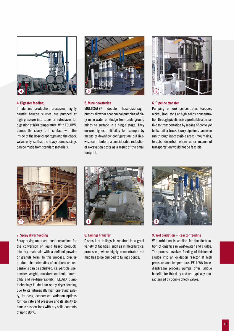
4. Digester feedingIn alumina production processes, highly caustic bauxite slurries are pumped at high pressure into tubes or autoclaves for digestion at high temperature. With FELUWA pumps the slurry is in contact with the inside of the hose-diaphragm and the check valves only, so that the heavy pump casings can be made from standard materials.
5. Mine dewateringMULTISAFE® double hose-diaphragmpumps allow for economical pumping of dir-ty mine water or sludge from underground mines to surface in a single stage. They ensure highest reliability for example by meansofdownflowconfiguration,but like-wise contribute to a considerable reduction of excavation costs as a result of the small footprint.
6. Pipeline transferPumping of ore concentrates (copper, nickel, iron,etc.)athighsolidsconcentra-tion through pipelines is a profitable alterna-tive to transportation by means of conveyor belts, rail or truck. Slurry pipelines can even runthroughinaccessibleareas(mountains,forests, deserts), where other means oftransportation would not be feasible.
4 5 6
7 8 9
7. Spray dryer feedingSpray drying units are most convenient for the conversion of liquid based products into dry materials with a defined powder or granule form. In this process, precise product characteristics of solutions or sus-pensions can be achieved, i.e. particle size, powder weight, moisture content, poura-bility and re-dispersability. FELUWA pump technology is ideal for spray dryer feeding due to its intrinsically high operating safe-ty, its easy, economical variation options forflowrateandpressureanditsabilitytohandle suspensions with dry solid contents of up to 80 %.
8. Tailings transferDisposal of tailings is required in a greatvariety of facilities, such as in metallurgical processes, where highly concentrated red mud has to be pumped to tailings ponds.
9. Wet oxidation – Reactor feedingWet oxidation is applied for the destruc-tion of organics in wastewater and sludge. The process involves feeding of thickened sludge into an oxidation reactor at high pressure and temperature. FELUWA hose-diaphragm process pumps offer unique benefits for this duty and are typically cha-racterised by double check valves.
11

4
1 2 3
F E L U WA Hose -D i aph r a gm Pumps
12

1. MULTISAFE® Double Hose-Diaphragm Pump Type TG 70 – 3 DS 1 Q = 0.5 m³/h p = 100 bar P = 2.2 kW Application: Coal gasification
2. MULTISAFE® Double Hose-Diaphragm Pump Type TG 100 – 3 DS 4 Q = 3 m³/h p = 100 bar P = 15 kW Application: Spray dryer feeding – Tannin dyestuff
3. MULTISAFE® Double Hose-Diaphragm Pump Type TG 40 – 4 DS 1 Q = 4 x 0.131 m³/h p = 25 bar P = 1.5 kW Application: Spray dryer feeding – Calcined titanium dioxide
4. 3 sets of Hose Diaphragm Piston Pumps Quadruplex design Type DG 250 – 4 SM 460 Q = 53 m³/h p = 96 bar P = 200 kW Application: Coal gasification
5. MULTISAFE® Double Hose-Diaphragm Pump Triplex design with PTFE diaphragm Type TG 200 – 3 DS 35 - P Q = 10 m³/h p = 100 bar P = 45 kW Application: Chemical industry
6. 3 sets of MULTISAFE® Double Hose-Diaphragm Pumps Triplex design Type TGK 400 – 3 DS 230 Q = 95 m³/h p = 120 bar P = 450 kW Application: Aluminium industry – Red mud 7. MULTISAFE® Double Hose-Diaphragm Pump Triplex design Type TGK 400 – 3 DS 230 Q = 150 m³/h p = 105 bar P = 450 kW Application: Chemical industry 8. 3 sets of Hose Diaphragm Piston Pumps Quadruplex design Type DG 250 – 4 SM 460 Q = 55 m³/h p = 100 bar P = 250 kW Application: Coal gasification
9. 4 sets of MULTISAFE® Double Hose-Diaphragm Pumps Triplex design Type TG 200 – 3 DS 100 Q = 40 m³/h p = 80 bar P = 132 kW Application: Coal gasification
5 6
7
8
9
13
Modu l a r De s i g n
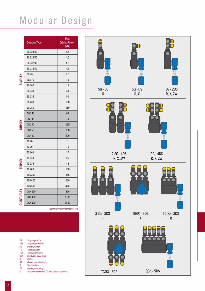
SG Simplex gearboxSGK Simplex crank driveDG Duplex gearbox TG Triplex gearboxTGK Triplex crank drive QGK Quintuplex crank driveK Piston DS Double hose-diaphragmR Vee belt driveZW Duplex pump designX Available with in-built FELUWA piston compressor
* guide value at medium stroke rate
SG-DSR
SG-DSR, X
SG-2DSR, X, ZW
2SG-4DSR, X, ZW
DG-4DSR, X, ZW
3SG-3DSR
TG(K)-3DSX
TG(K)-3DSR
TG(K)-6DS QGK-5DS
Gearbox TypeMax.
DrivingPower*(kW)
SG 124/40 4.5
SG 224/40 4.5
SG 132/40 4.5
SG 232/40 4.5
SG70 7.5
SGK70 10
SG 100 15
SG 130 30
SG 135 50
SG 200 100
SG 250 150
DG130 60
DG135 70
DG200 155
DG250 350
DG400 600
TG 40 3
TG70 15
TG 100 17
TG 130 26
TG 135 48
TG 200 100
TGK 300 355
TGK 400 650
TGK 500 2800
QGK 250 450
QGK 400 1100
QGK 500 3500
SIM
PLEX
DUPL
EXTR
IPLE
XQU
INTU
PLEX
14
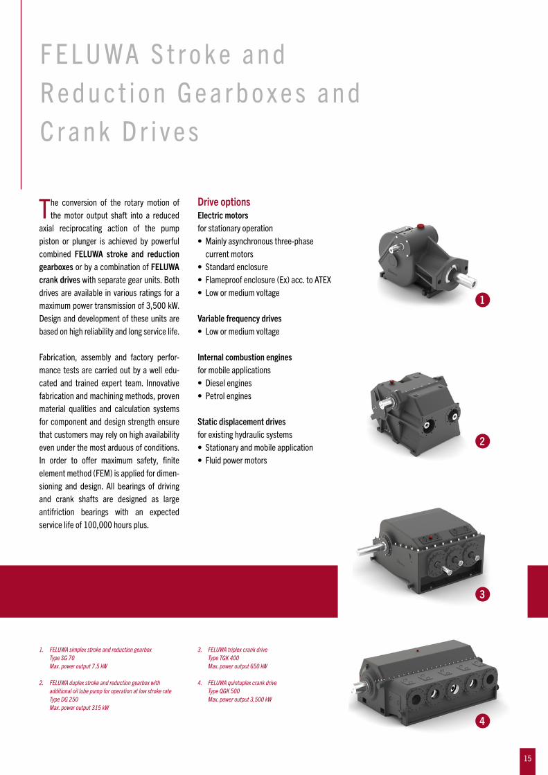
The conversion of the rotary motion of the motor output shaft into a reduced
axial reciprocating action of the pump piston or plunger is achieved by powerful combined FELUWA stroke and reduction gearboxes or by a combination of FELUWA crank drives with separate gear units. Both drives are available in various ratings for a maximum power transmission of 3,500 kW. Designanddevelopmentoftheseunitsare based on high reliability and long service life.
Fabrication, assembly and factory perfor-mance tests are carried out by a well edu-cated and trained expert team. Innovative fabrication and machining methods, proven material qualities and calculation systems for component and design strength ensure that customers may rely on high availability even under the most arduous of conditions. In order to offer maximum safety, finite elementmethod(FEM)isappliedfordimen- sioning and design. All bearings of driving and crank shafts are designed as large antifriction bearings with an expected service life of 100,000 hours plus.
Drive optionsElectric motorsfor stationary operation• Mainlyasynchronousthree-phase current motors• Standardenclosure• Flameproofenclosure(Ex)acc.toATEX• Lowormediumvoltage
Variable frequency drives• Lowormediumvoltage
Internal combustion enginesfor mobile applications• Dieselengines• Petrolengines
Static displacement drivesfor existing hydraulic systems• Stationaryandmobileapplication• Fluidpowermotors
F E L U WA S t r o k e a n d R e d u c t i o n G e a r b o x e s a n d C rank D r i v e s
1. FELUWA simplex stroke and reduction gearbox Type SG 70 Max. power output 7.5 kW
2. FELUWA duplex stroke and reduction gearbox with additional oil lube pump for operation at low stroke rate Type DG 250 Max. power output 315 kW
3. FELUWA triplex crank drive Type TGK 400 Max. power output 650 kW 4. FELUWA quintuplex crank drive Type QGK 500 Max. power output 3,500 kW
1
2
3
4
15
SpecialDesignsofMULTISAFE® DoubleHose-DiaphragmProcessPumps
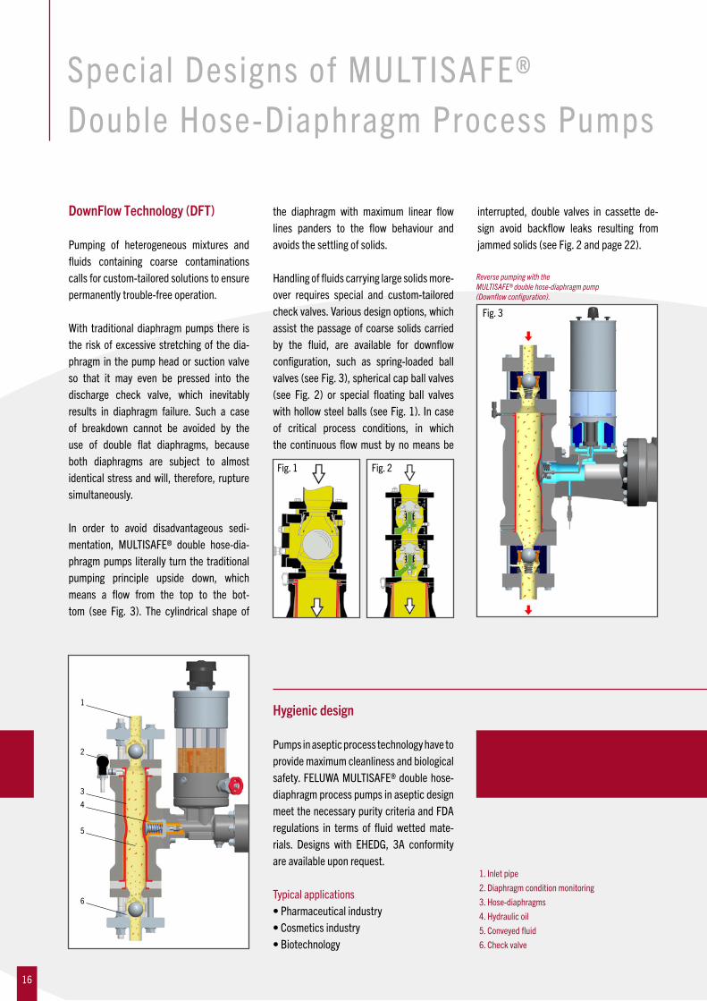
DownFlow Technology (DFT)
Pumping of heterogeneous mixtures and fluids containing coarse contaminationscalls for custom-tailored solutions to ensure permanently trouble-free operation.
With traditional diaphragm pumps there is the risk of excessive stretching of the dia-phragm in the pump head or suction valve so that it may even be pressed into the discharge check valve, which inevitably results in diaphragm failure. Such a case of breakdown cannot be avoided by the use of double flat diaphragms, becauseboth diaphragms are subject to almost identical stress and will, therefore, rupture simultaneously.
In order to avoid disadvantageous sedi-mentation, MULTISAFE® double hose-dia-phragm pumps literally turn the traditional pumping principle upside down, which means a flow from the top to the bot-tom (see Fig. 3). The cylindrical shape of
the diaphragm with maximum linear flow lines panders to the flow behaviour and avoids the settling of solids.
Handlingoffluidscarryinglargesolidsmore- over requires special and custom-tailored check valves. Variousdesignoptions,whichassist the passage of coarse solids carried by the fluid, are available for downflowconfiguration, such as spring-loaded ball valves(seeFig.3),sphericalcapballvalves(see Fig. 2) or special floating ball valveswithhollowsteelballs (seeFig.1). Incaseof critical process conditions, in which the continuous flowmust by nomeans be
interrupted, double valves in cassette de-sign avoid backflow leaks resulting fromjammedsolids(seeFig.2andpage22).
Hygienic design
Pumps in aseptic process technology have to provide maximum cleanliness and biological safety.FELUWAMULTISAFE®doublehose-diaphragm process pumps in aseptic design meetthenecessarypuritycriteriaandFDAregulations in terms of fluid wetted mate-rials. Designs with EHEDG, 3A conformity are available upon request.
Typical applications•Pharmaceuticalindustry•Cosmeticsindustry•Biotechnology
1. Inlet pipe2.Diaphragmconditionmonitoring3. Hose-diaphragms4. Hydraulic oil5.Conveyedfluid6. Check valve
Reverse pumping with the MULTISAFE® double hose-diaphragm pump (Downflow configuration).
Fig. 1 Fig. 2
Fig. 3
6
5
4
3
1
2
16

... for extreme pumping temperatures
High efficiency at extreme pumping temperaturesAlso in terms of pumping temperature the modular system of double hose-diaphragm pumps includes a great variety of options, such as
• Designswithribbedcasingarea (convector)• Designswithcoolingorheatingjacket• Designswithdoublehose-diaphragms andadditionalflatdiaphragm
Elastomer hose-diaphragms are generally employed up to 130 °C. PTFE components, specially developed for hose-diaphragm pumps, have proven their effectiveness for higher temperatures up to 200 °C. These can also be employed if the pumped medi-um is characterised by extremely aggressive chemical properties. The pumps are equipped with ribbed sur-faces between the wet and drive ends to master extreme temperatures ≥ 200 °C. These also ensure effective heat dissipation.
MULTISAFE® double hose-diaphragm pump with ribbed casing area (convector).
Variants with double redundantdiaphragms
The combination of a double hose-dia-phragm and flat diaphragm represents afurther option for extreme pumping tempe-ratures and/or high suction pressures.
Double redundant MULTISA-FE® pump with double hose-diaphragms made of special PTFE and additional flat dia-phragm for extreme pumping temperatures and/or high suc-tion pressure.
Pump with cooling or heating jacket (optional for check valves)
Some media require a minimum tempera-ture if theyare to retain theirpositiveflowcharacteristics. In the event of a tempera-ture drop, they will become very viscous,
solidify or crystallise. Hose-diaphragm housing and, where necessary, valve ca-singandconnectionflangearefittedwithaheating jacket to ensure pumpability of the product.
MULTISAFE® double hose-diaphragm pump with cooling/heating jacket (convector).
17

... for toxic or explosive fluids
Whenpumpingaggressiveandtoxicfluids,the utilisation of hermetically sealed and low-maintenance pumps is vital.
Unique operating safetyWet and drive end of MULTISAFE® hose-diaphragm pumps are not separated by the traditionalflatdiaphragm,butbymeansofapair of redundant double hose-diaphragms. With maximum linear flow lines the pumpis therefore also capable of handling toxic, explosive, corrosive and erosive chemicals at minimum wear. For extremely critical fluids the use of the remote head designwith separation of wet end and dry end is recommendable.
Even in the event that one of the two hose- diaphragms leaks, the conveyed fluid will neither come into contact with the pump casing nor with the dynamic seals. The second hose-diaphragm ensures that pump operation can be maintained until the next planned shut-down of the unit.
… with dead space reducing cylinder
Gasorair,entrained intheconveyedfluid,must be compressed during the pumping actioninordertoavoidalossinflowrate.Bymeans of a so-called dead space reducing cylinder in the hose-diaphragm, the volume ofthefluidchamberisreducedtominimum.Thus, entrapped gas bubbles are automati-cally compressed and the hydraulic efficien-cy of the pump is optimised.
Design with dead space reducing cylinder for the handling of fluids with rather high entrained gases.
Remote head design with diagnostic systems for delivery valves and hose-diaphragms.
18

Control Systems of MULTISAFE®DoubleHose-DiaphragmPumps andHoseDiaphragmPistonPumps
VF = volumetric displacementVK = volumetric piston displacementVL = continuous bleed volumeVLE = leakage compensation volume (via make-up device)VSM = volumetric hose-diaphragm displacementVÜ = volume diverted into the oil storage tank via the pressure relief valve
Mechanical leakage control
Loss of hydraulic fluid (VL, VÜ, VB) is auto-matically compensated by FELUWA pumps. For these situations the pumps are provided with a unique mechanical leakage con-trol and compensation device within the hydraulic chamber. This system operates fully automatically, neither requires a separate oil pump nor a control system and is moreover easy to maintain.
During the suction stroke, the diaphragm(either hose-diaphragm or flat diaphragm,depending on the pump type) is drawn towards the hydraulic chamber of the pis-ton or plunger. If the hydraulic oil volume decreases due to leakage, the diaphragm will actuate a control disc, which in turn opens the compensation valve via a lever. Further backward movement of the piston/ plunger causes a vacuum in the actuation chamber, since the diaphragm cannot move any further. As soon as the vacuum
exceeds the setting range of the compensa-tingvalve(make-upvalve),thevalveopens. Theactuationfluid(VL,VÜ,VB)thathadbeendisplaced into the oil reservoir during the delivery stroke is replenished during the increased suction stroke. By this means,
themissing volume of hydraulic fluid (VLE) is replaced in the hydraulic chamber. Since the compensating valve cannot open unless the leakage control valve is mechanically opened by a lever, it is ensured that the dia-phragms cannot be overstretched.
Condition monitoring of hose-diaphragm clamping
Particularly when it comes to the handling of toxic or other fluids that are harmful tothe environment or to aseptic process engi-neering applications, condition monitoring of diaphragms has to be extended to the clamping area. For this reason, a unique and redundant diaphragm clamping system has been developed for MULTISAFE® doublehose-diaphragm process pumps. It allows for permanent monitoring of the clamping area and reliable prevention of leaks. The monitoring provides for triple differentiation in order to cover different leak possibilities. Elastic distortion of hose-diaphragms is path-controlled and effected in a concentric
manner due to their inherent construction. The space between both hose-diaphragms is unpressurised and ends in a central transfer point. In the event that one of the hose-diaphragms leaks or fails, either pro-duct or hydraulic fluid will penetrate intothe unpressurised intermediate space. The resulting build-up of pressure is automati-cally fed to the hose-diaphragm condition monitoring system (measuring point P1)and activates the respective electrical con-tactorpressuresensor(signaltransmitter).Measuring point P2 checks the sealing to-wards the wet end and the clamping of the primary(inner)hose-diaphragm.Measuringpoint P3 is allocated to the sealing of the hy-draulic end and clamping of the secondary (outer)hose-diaphragm.
19

Bypass flow control
A bypass system which functions in the same manner as the pressure relief valve is fitted to the pump as an option for short-term flow control. Essentially, with eachdelivery stroke of the pump, an infinitely adjustable portion of the hydraulic oil (VB)displaced by the piston/plunger is diverted into the hydraulic oil reservoir. Since the volume being displaced by the piston/ plunger onto the diaphragm (either hose-diaphragmorflatdiaphragm,dependingonthe pump type) is reduced by the volume being diverted into the hydraulic oil reser-voir, the output of the pump decreases accordingly.
The bypass control is only designed for a relatively low driving power up to 5.5 kW or for short-term control (e.g. during systemstartup).Alternatively,briefopeningof thebypass valve during pump startup generally enables relatively rapid bleeding and diaphragm positioning in line with the design.
Pressure relief valve
Each pump head is provided with an in-dividual, easily accessible pressure relief valve in the hydraulic fluid. This valve isset to the exact nominal pressure required during the works test run of the pump. If an over-pressure situation becomes evident in the hydraulic fluid, i.e. due to a closed discharge sluice valve, the pressure reli-ef valve will open, thus relieving hydraulic fluid (VÜ) into the hydraulic oil reservoir.From this reservoir the oil is automatically returned into the pump chamber via the leakage compensating valve. The relief valve protects the pump as well as the gear-box from overload which may arise from an erroneously closed isolating valve or from a blocked discharge pipe etc.
Pressure relief valves are also available with type approval and with lead seal.
VF = volumetric displacementVK = volumetric piston displacementVL = continuous bleed volume
VLE = leakage compensation volume (via make-up device)VSM = volumetric hose-diaphragm displacementVÜ = volume diverted into the oil storage tank via the pressure relief valve
20

FELUWACheck Va lves i n Casset te Des ign
Check valves rank among the key compo-nents of positive displacement pumps.
With FELUWA MULTISAFE® double hose-diaphragm pumps and hose diaphragm pis-ton pumps, the suction and discharge check valves are to be considered as the sole real wearing parts. For this reason, the achieve-ment of utmost lifetime is paramount when designing the valves. FELUWA check valves are individually adapted to the application, both with regard to flow velocity and theselection of material and flow geometry.They are of modular cassette design, which allows for the utilisation of ball or cone val-ve trims with the same valve casing. The cassettes are hinge-mounted between the pump head and suction or discharge manifold, respectively. For maintenance purposes, the complete valve assembly is easily removable like a cassette by means of jacking bolts, without prior dismantling of adjacent elements or piping. Removal neither requires skilled personnel nor special tools. This allows for minimum down-time for service and maximum availability.
Swiveling of double valves with-out pipe removal.
FELUWA valve casings are suitable for a great variety of valve trims. Ball valve trims are characterised by a considerably smaller number of parts than cone valves (3 vs. 7).
21

FELUWACheck Va lveDes ign Opt ionsFELUWA has at its base in excess of 60 years experience in the design and fabrication of check valves for positive displacement pumps. Suction and discharge valves are available as ball, coneorplatevalveswithagreatvarietyofdifferentdesigns,suchas:
Ball valve with metal and additional soft seal Ball valve made of polypropylene with steel reinforcement Double ball valve with reversible valve seat
Spring-loaded plate valve
Spring-loaded cone valve Spring-loaded downflow cone valve Spring-loaded downflow ball valve
TopEntry valve design with FELUWA Quick Change System
Double ball valves are specified for media with high levels of impurities and applications which require a particularly high continuous flow (e.g. gasifier feed pumps in coal gasification systems). If, in the short term, a particle is jammed in one valve, the second valve ensures effective sealing, thus preventing medium backflow and a resulting flow loss.
22

Onl ine D iagnost ic Systems
Pump Condition Guard (PCG)
MULTISAFE®doublehose-diaphragmpumps are designed to avoid sudden deviation from admissible working conditions and
unplanned downtime. For additional back-upof failsafe characteristics,MULTISAFE®pumps utilise an overall diagnostic system for permanent condition monitoring of es-sential components and parameters. The
readings are saved with trend and allow for complete backtracking of the history over several weeks.
Acoustic valve diagnostics for early recognition of wear in delivery valves
FELUWA Valve Performance Monitoring System (FVPMS)For early recognition of wear in delivery valves, FELUWA has developed specific diagnostic equipment. The measuring prin-ciple is capable of detecting leaks, even if the loss of output is still less than 1.5 %. By meansoftheFVPMSdiagnosticsystem,theoperational safety and availability of pumps is significantly increased, since wear is precisely localised and detected at an early stage which allows for specific forward planning of service and repair.
PVD Powerlosscausedbyvalveleakage(duetowear) during the discharge stroke
PVS Powerlosscausedbyvalveleakage(duetowear) during the suction stroke
≤
≤
Pre-CompressionHydraulic Temperature
Valve Wear
Suction Pressure
Hose-DiaphragmTemperature and Flow of Gearbox Oil
Motor TemperatureTemperature and Flow of Intermediate Gearbox Oil
MonitoringSystem
PLCFrequency Converter
Local
DCS
RemoteService
23

Efficient diagnostics for mechanical and plant engineering
Condition monitoring of the most essential pump components and parameters enables preventive maintenance, increases pump availability and reduces cost of ownership. For this reason FELUWA has developed a unique “4 in 1” diagnostics system whichallows operators to monitor four of the most important parameters.
Diagnostics for hose-diaphragms: Hose-Diaphragm Guard (HDG)Whereas traditional diaphragm piston pumps require conductivity measurement systems, permanent condition monitoring of MULTI-SAFE®hose-diaphragmsisensuredbymeansof pressure sensors, pressure gauges or con-tact pressure gauges. In the event that one of the hose-diaphragms leaks or fails, either productoractuationfluidwillpenetrateintothe unpressurised intermediate space. The resulting build-up of pressure is led to the condition monitoring system, which in turn provides a signal with manifold processing options. Nevertheless, operation can be main- tained with a single hose-diaphragm until the system allows for shutdown and repair.
Diagnostics for check valves:FELUWA Valve Performance MonitoringSystem (FVPMS)Permanent condition monitoring of indi-vidual check valves is effected by means of acoustic sensors which are fixed to the outside of the valve casing. They are not in contact with the product and easily retrofittable. The sensor is capable of detec-ting leaks, even if the loss of output is still less than 1.5 %. By means of the FVPMS
(FELUWA Valve Performance Monitoring System)diagnosticsystem,theoperational safety and availability of pumps is signifi-cantly increased, since wear is precisely localised and detected at an early stage which allows for specific forward planning of service and repair. For details see page 23.
Diagnostics for suction pressure: Suction Guard (SG)Unrestricted inflow at an appropriate inlet pressure is essential for trouble-free opera-
tion. For reliable supervision of suction pressure, diaphragm-type pressure gauges are applied which have especially been designed by FELUWA for slurry handling applications.
Diagnostics for hydraulic and gearbox temperature: TempGuard (TG)Supervision of hydraulic and gearbox oil temperature is carried out by means of PT 100 temperature sensors.
4 in 1 D iagnost ics4 in 1 System
ConditionMonitoringof:• Checkvalves• Hose-diaphragms• Inlet/Suction pressure• Hydraulic/Gearbox temperature
For condition monitoring, va-rious means are available for an optimum link to local pro-cess control systems, such as communication via Foun-dation Profibus or Fieldbus.
FVPMSSensorSignal ProcessingPressure MeasurementAdapterScrew PlugCheckValve
Sensor at the valve casing(FVPMS)
Pressure sensor(HDG)
Valve sensor(FVPMS)
Special diaphragm-type pressure gauge (SG)
Pressure gauge(HDG)
Contact pressure gauge(HDG)
PT 100(TG)
24

FelWebGuard (FWG): Working principleThe system is linked to the Internet. In the event that actual values differ from the pro-grammed nominal values, the system will email an according notification to a FELUWA service technician. In addition, a safe, bidi-rectionalVPNconduitcanbesetup,whichallows for remote access to the control unit of the pump. The system not only allows for higher availability and productivity, but also for a reduction in service costs.
Configuration
• Parameterisation• Accesstoserviceintervals• Accesstospecificdocumentation• SetupofabidirectionalVPNconduit for web-based service by a FELUWA service technician
FelWebGuardThe Internet has developed into a comprehensive medium for the transfer of all kinds of data. In times of“Industry4.0” FELUWA increasingly focuses onwireless data communication andbenefits from the new prospects resulting thereof.
Touch panelsFor early detection of faults and with the objective of ensuring maximum availability FELUWA supports the redundant nature of MULTISAFE® double hose-diaphragmpumps by means of an overall diagnostic system. Touch panels, which are integrated into the control cabinet, give the pump a transparent character and provide the ope-rator with information on current operating parameters and the condition of fundamen-tal parts. Bus systems link the touch panel tolocalprocesscontrol,wherebyPROFIBUS
(ProcessFieldBus)providesbestconditionsfor communication and control of system frequency converters, PLC, touch panels and the FVPMS (FELUWA Valve Perfor-manceMonitoringSystem).
The pump can either be controlled via the frequency converter panel, the FELUWA touch panel of the local control or via client’s DCS system with setpoint setting(via analogue input 4 to 20 mA). Touchpanels provide time-related recording and directorremoteinsightintocheckvalves(via
FVPMS), primary and secondary hose-dia-phragms, suction and discharge pressure, hydraulic and gearbox oil temperature, stroke rate, pre-compression of accumula-tors to pulsation dampeners, oil lube sys-tems of crank drive and intermediate gear (includingtemperature,pressureandflow),motor (including measurement of torque,absorbedpowerandFELUWApumpspeed),transformerandfrequencyconverter(varia-blefrequencydrive).
Display of all critical parameters by means of traffic light logic.
OK Warning Alarm
Three triplex sets of FELUWA MULTISAFE® pumps discharging into a common main. FELUWA pump synchronisation controls phase shift and eliminates excitation of resonances significantly.
FELUWA touch panel
25

A typical characteristic of oscillating dis-placement pumps is the hydro-dynamic
independencyofthedeliveryflowfromthepressure and vice versa. The reason for this feature is due to the mechanics of pressure generation by means of a displacement piston which prevents backflow and thus an escape of the displaced volume into the pipework. This principle allows for the achievement of extraordinarily high hy draulic efficiencies of up to 96%. Conversely, the oscillating movement causes undesirable flow fluctuations and pressure pulsations. To avoid such pressure pulsations, an array of different pul sation dampenersisemployed.Dependentontheactual working conditions, traditional pulsa-tiondampeners (pressure air vessels)with air or gas cushion or so-called hose-dia-phragmpulsation dampeners (PULSORBER) with nitrogen-filled accumulators are applied.
PulsationDampening
Pulsation dampening by means of FELUWA hose-diaphragm pulsation dampener with additional air vessel effect.
MULTISAFE® double hose-diaphragm pump with standard suction air vessel and discharge roller diaphragm pulsation dampener PULSORBER 900.
1. Hose-diaphragm pulsation dampener2. Bladder-type accumulator3. Pressure gauge
4. Piping with conveyed fluid5. Check valve6. Oscillating displacement pump
Delivery flow characteristics
Q
Q
Q
Q
Q
Q
Single-acting single-cylinder pump
Double-acting single-cylinder pump with double-sided piston rod
Double-acting twin-cylinder pump with single-sided piston rod
Double-acting twin-cylinder pump with one-piece piston rod
Single-acting three-cylinder pump
Single-acting five-cylinder pump
φ
φ
φ
φ
φ
φ
1
2 3
4 5 6
26

In-built FELUWA piston compressor
When using standard air vessels or hose-diaphragm pulsation dampeners, the at-tainable residual pulsation depends on the compressed gas volume above the liquid column within the pressure vessel. How-ever, there is a constant loss (solution) ofgas at the contact surface of the conveyed
fluidwhichreducesthedampeningvolumeaccordingly. The compensation of this loss within the air vessel requires periodic refil-ling by means of costly monitoring and filling devices equipped with shut-off and control units. For this purpose, FELUWA has deve-loped an ingenious and most effective “in-builtpistoncompressor”.Witheachpistonstroke, it feeds a small quantity of gas or
atmospheric air into the discharge air vessels. The attainable pressure of the pump piston compressor is always considerably higher than the maximum pump pressure. Thisensuresthattheconveyedfluidcannotflow back to the pump piston compressorunder normal working conditions.
AirVesselsandIn-Built Piston Compressors
Hose diaphragm piston pump with discharge air vessel and in-built piston compressor.
Pressure air vessels
In order to ensure high effectiveness of pul-sation dampening, liquid columns should be kept as low as practicable. For this reason, air vessels are mounted as close as possible to the pump heads, which means directly above the discharge and below the suction valves. The dampening behaviour depends on the different pulsation dampener de-signs. With traditional pressure air vessels, the gas cushion is held directly above the conveyedfluid.Underpeakpressuresand/or excessive flow, this cushion is com-pressed above thefluid level and releasedduring the suction stroke of the pump. The fluid is then displaced into the dischargepipe and minimises pulsations accordingly.
Working principle
With each return stroke of the piston rod, a small volume of filtered air (or gas) is sucked into the compressor chamber via a valve. With the forward stroke of the piston rod this air volume is fed via the non-return valve into the air vessels. This procedure is repeated with each stroke of the pump and is only active when the pump is operating.
By this means, costly starting and stopping of air injection devices is fully eliminated and the available air volume within the air vessels is always maintained at an optimum level. The attainable residual pulsation is re-duced to a minimum. At high pressure and/or applications which require frequent and fast filling of the air vessels, the suction end of the in-built piston compressor may addi-tionally be fed by compressed air.
MULTISAFE® double hose-diaphragm pump with pressure air vessel.
27

For working pressures in a range of ≥ 40 bar and such products that do not allow
for contact with air or gas, considerably more efficient hose-diaphragm pulsati-on dampeners are applied. The FELUWA PULSORBER consists of a hose-dia-phragm pulsation dampener and bladder accumulator. The system offers all the advantages of a conventional pressure air vessel. It is designed to store the pumped volume over and above the average, pro-duced during every delivery stroke, in the hermetically sealed nitrogen accumulator. This volume is then released again during the piston suction stroke, thus compensa-tingforunavoidabledeliveryfluctuations.
The accumulator is pre-charged to approx. 80 % of the working pressure in order to ensure maximum efficiency. When ope-rating at different discharge pressures, pre-compression has to be adapted accordingly. In comparison to typical bladder-type accumulators, the FELUWA PULSATROL with roller diaphragm accu-mulator offers a unique advantage in that the nitrogen cushion can be individually adapted to the operating conditions by means of an automatic filling unit. The position of the roller diaphragm is detected
by utilisation of inductive transmitters. Based on this position, a co-efficient of operating pressure and pre-compressi-on can be calculated. By means of this co-efficient, the control unit determines whether pre-compression has to be in- creased or decreased and nitrogen has to beadded(V2)ordrained(V1),respectively.
The FELUWA PULSATROL is, therefore, not sensitive to operating conditions which deviate from the design layout and allows for a reduction of the uniformity coefficient tolessthan0.5%(ptop).
PULSATROL
piston1
piston2
piston3
volu
me fl
ow Q
crank angle
flow with FELUWA pulsation dampener
mean flow
volume shortage
excess volume
Optimum pulsation reduction by means of FELUWA PULSORBER.
)(
N
P1
I1
I2
I3
V1 V2
FELUWA PULSATROL pulsation dampener with roller diaphragm accumulator and au-tomatic adaptation of the pre-compression to varying working pressures.
28

C o n v e r s i o n Ta b l e s a n d M at e r i a l s
Length (L)1 in = 25.4 mm
1mm = 0.03937in
1 ft = 30.48 cm
1 metre = 3.28083 ft
1 micron = 0.001 mm
Density (ρ)1 lb/ft³ = 16.018 kg/m³
1lb/ft³ = 0.0005787lb/in³
1 kg/m³ = 0.06243 lb/ft³
1 g/cm³ = 0.03613 lb/in³
Performance (F)1 PS = 33 000 ft lb/min
1 PS = 550 ft lb/sec
1 PS = 2 546.5 B.T.U./hr
1PS = 745.7Watt
1 Watt = 0.00134 PS
1 Watt = 44.254 ft lb/min
Area (A)1 in² = 6.4516 cm²
1 ft² = 929.03 cm²
1 cm² = 0.155 in²
1cm² = 0.0010764ft²
1m² = 10.764ft²
1 ft² = 0.09290304 m²
Flow (Q) Mass1 lb/h = 0.4536 kg/h
1 kg/h = 2.205 lb/h
Flow (Q) Volume1 ft³/sec = 448.83 USGPM
1 ft³/sec = 1699.3 l/min
1 USGPM = 0.002228 ft³/sec
1 USGPM = 0.06308 l/sec
1 cm³/sec = 0.0021186 ft³/min
Volume (V)1in³ = 16.387cm³
1 ft³ = 28316 cm³
1 ft³ = 6.229 Imp.gal
1ft³ = 7.4805USgal
1ft³ = 28.317litre
1USgal = 0.1337ft³
1 USgal = 231 in³
1USgal = 3.785litre
1 Imp.gal = 1.20094 USgal
1Imp.gal = 277.3in³
1 Imp.gal = 4.546 litre
1 litre = 61.023 in³
1 litre = 0.03531 ft³
1 litre = 0.2642 USgal
Pressure (p)1 in water = 0.03613 lb/in²
1 ft water = 0.4335 lb/in²
1ftwater = 0.88265”Hg
1 in Hg = 0.49116 lb/in²
1 in Hg = 1.13299 ft water
1 atmosphere = 14.696 lb/in²
1atmosphere = 760mmHg
1 atmosphere = 33.899 ft water
1psi = 27.70“water
1psi = 2.036”Hg
1psi = 0.0703066kg/cm²
1 psi = 6895 Pa
1 kg/cm² = 14.223 lb/in²
1 MPa = 145 lb/in²
1 bar = 0.1 MPa
1bar = 14.50377psi
Metric pressure unitsUnit bar mbar kbar Pa kPa Mpa
1 bar 1 1000 0.001 105 100 0.1
1 mbar 0.001 1 10-6 100 0.1 10-4
1 kbar 1000 106 1 108 105 100
1 Pa 105 0.01 10-8 1 0.001 10-6
1 kPa 0.01 10 10-5 1000 1 0.001
1 Mpa 10 104 0.01 106 1000 1
1 Pa = 1 N/m2 1 kPa = 1kN/m2 1MPa = 1MN/m2
Velocity (v)1 ft/sec = 30.48 cm/sec
1 cm/sec = 0.032808 ft/sec
Energy (E)1 kW h = 2.655 x 106 ft lbs
1 kW h = 1.3410 PS h
1 kg cal = 3.968 B.T.U.
Thermal transfer (Q)1 g cal/cm2 =3.687B.T.U./ft2
1 kg cal/hr/m2/°C = 0.205 B.T.U./hr/ft2/°F
Weight1 oz = 28.35 g
1g = 0.03527oz.
1 lb = 453.59 g
1 g = 0.0022046 lb
1 lb = 0.4535924 kg
1 kg = 2.205 lb
1 USgal water = 8.33 lb
1 in³ water = 0.0361 lb
1 Imp.gal water = 10.04 lb
Temperature (T)To / from Kelvin scale (K) Celcius scale (°C) Fahrenheit scale (°F)
TKelvin TK TK+273.15 (TF+459.67)·5/9
TCelsius TK-273.15 TC (TF-32)·5/9
TFahrenheit TK·1.8-459.67 TC·1.8+32 TFTRankine TK·1.8 TC·1.8+491.67 TF+459.67
Viscosity (η and ν)1centipoise=0.000672lb/ft2
1centistoke=0.00001076ft2/sec
60 years of experience in materials selection Appropriate material selection is one of the keys for successful installations. FELUWA can rely on more than 60 years’ experience in material selection for even the most critical duties. All materials are individually determined with respect to chemical and
mechanical resistance of the conveyed pro-duct. Apart from standard casting materials and steels, a great variety of stainless steels are applied, such as martensitic, ferritic, semi-austenitic, austenitic, ferritic-austeni-tic (duplex and super duplex) steels, nickelor copper-based special alloys or titanium. Typicalmaterialsofflatdiaphragmsandhose-
diaphragms are NBR (nitrile rubber), CR(chloroprene rubber), FPM (fluororubber),HNBR(hydrogenatednitrilerubber),IIR(butylrubber), EPDM (ethylene propylene diene ca-outchouc), silicon rubber, AU (polyurethane)and special mixtures of PTFE (polytetrafluorethylene).Metaldiaphragmsareavailableuponrequest.
29
C o m p a r i s o n w i t h c o n v e n t i o n a lPis ton D iaphragmPumps
Conventional FELUWA Technology
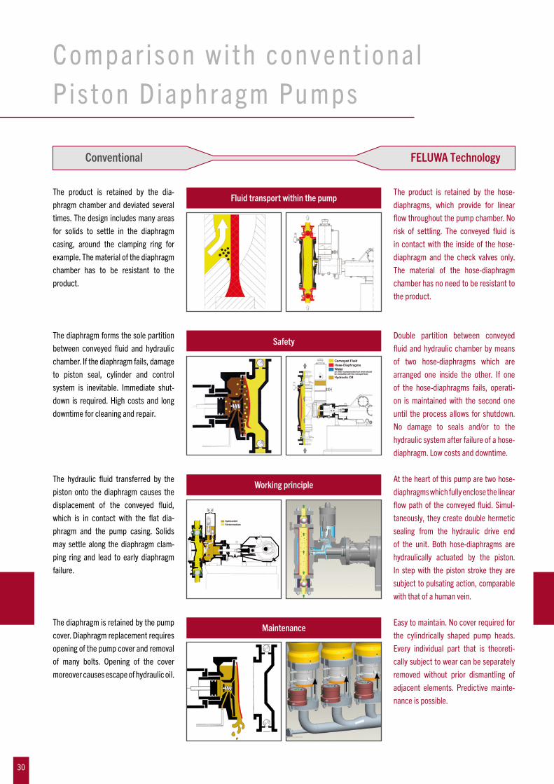
The product is retained by the dia-phragm chamber and deviated several times. The design includes many areas for solids to settle in the diaphragm casing, around the clamping ring for example. The material of the diaphragm chamber has to be resistant to the product.
The product is retained by the hose-diaphragms, which provide for linear flowthroughoutthepumpchamber.Norisk of settling. The conveyed fluid isin contact with the inside of the hose-diaphragm and the check valves only. The material of the hose-diaphragm chamber has no need to be resistant to the product.
Fluid transport within the pump
The diaphragm forms the sole partition between conveyed fluid and hydraulicchamber. If the diaphragm fails, damage to piston seal, cylinder and control system is inevitable. Immediate shut-down is required. High costs and long downtime for cleaning and repair.
Double partition between conveyedfluidandhydraulicchamberbymeansof two hose-diaphragms which are arranged one inside the other. If one of the hose-diaphragms fails, operati-on is maintained with the second one until the process allows for shutdown. No damage to seals and/or to the hydraulic system after failure of a hose-diaphragm. Low costs and downtime.
Safety
The hydraulic fluid transferred by thepiston onto the diaphragm causes the displacement of the conveyed fluid,which is in contact with the flat dia-phragm and the pump casing. Solids may settle along the diaphragm clam-ping ring and lead to early diaphragm failure.
At the heart of this pump are two hose-diaphragms which fully enclose the linear flow path of the conveyed fluid. Simul-taneously, they create double hermetic sealing from the hydraulic drive end of the unit. Both hose-diaphragms are hydraulically actuated by the piston. In step with the piston stroke they are subject to pulsating action, comparable with that of a human vein.
Working principle
MaintenanceThe diaphragm is retained by the pump cover.Diaphragmreplacementrequiresopening of the pump cover and removal of many bolts. Opening of the cover moreover causes escape of hydraulic oil.
Easy to maintain. No cover required for the cylindrically shaped pump heads. Every individual part that is theoreti-cally subject to wear can be separately removed without prior dismantling of adjacent elements. Predictive mainte-nance is possible.
30

C o m p a r i s o n w i t h c o n v e n t i o n a lPis ton D iaphragmPumps
Conventional FELUWA Technology
As a result of damaged delivery valves, shutdown of the pump may result in the full system pressure being transferred onto the diaphragm, which causes the diaphragm to be pressed against the diaphragm support disc. Higher pres-sures may even cause perforation and early diaphragm failure.
In the event that the hose-diaphragm is loaded by the system pressure as a result of a leaking discharge valve, it is gently supported by the support disc and not damaged, even if the maximum delivery pressure is applied to one side.
Disassembly of suction and dischargepipe and of suction/discharge pulsation dampeners is required. For bigger units a crane is necessary. All fastening bolts need to be removed. High downtime.
Suction and discharge pulsation dam-peners remain in position and are lifted by means of two jacking bolts. The com-plete valve assembly can be withdrawn similar to a cassette without removal of pipework and/or adjacent elements. Long lifetime. Minimum downtime.
Special FELUWA hose-diaphragm pres-sure air vessel with accumulator which is pre-charged at approx. 80 % of actual working pressure guarantees optimum dampening of pulsations in valves and discharge pipes and ensures most uni-form output. Standard pressure air ves-sels are automatically ventilated during pump operation via in-built piston com-pressor(seeillustration).
Since the conveyed fluid is in contactwith the pump casing, cooling/heating is effected by double-walled casings orwithin the fluid chamber. The latter,however, increases the risk of settling along the cooling or heating spirals. Moreover,thecoolingorheatingfluidis gradually absorbed by the conveyed fluid. Therefore, regular compensationis required.
The product is not in contact with the pump casing. The cooling or heating agent is separated from the conveyed fluid by the hose-diaphragms only. With each stroke of the piston/plunger, the hose-diaphragm makes a pulsating movement so that sedimentation, which might restrict the heating/cooling efficiency, cannot occur.
Ventilation of pressure air vessels re-quires external compressed air supply. Permanent supervision is required. Caution:Incaseofaleakycheckvalveand open air supply valve, conveyed fluidmay stream into the compressedair supply pipe.
Delivery valve assembly
Pulsation dampening
Cooling and heating of wet end
Diaphragm protection system
31

FELUWA Pumpen GmbH
Beulertweg10|54570Mürlenbach|GermanyPhone+49(0)6594.10-0|Fax+49(0)[email protected] | www.feluwa.com
Engineered and Made in Germany Ref.Nr.:E21
009.05
16
100 200 300 400 500 600 700 800 900 1000
PN 63
PN 100
PN 160
PN 250
PN 320
PN 400
Pressure rating (bar)�
Capacity (m3/hr)�