host connection manualnb-series+hostconnmanual.pdf · section 11 connecting to keyence plcs this...
TRANSCRIPT
HOST CONNECTIONMANUAL
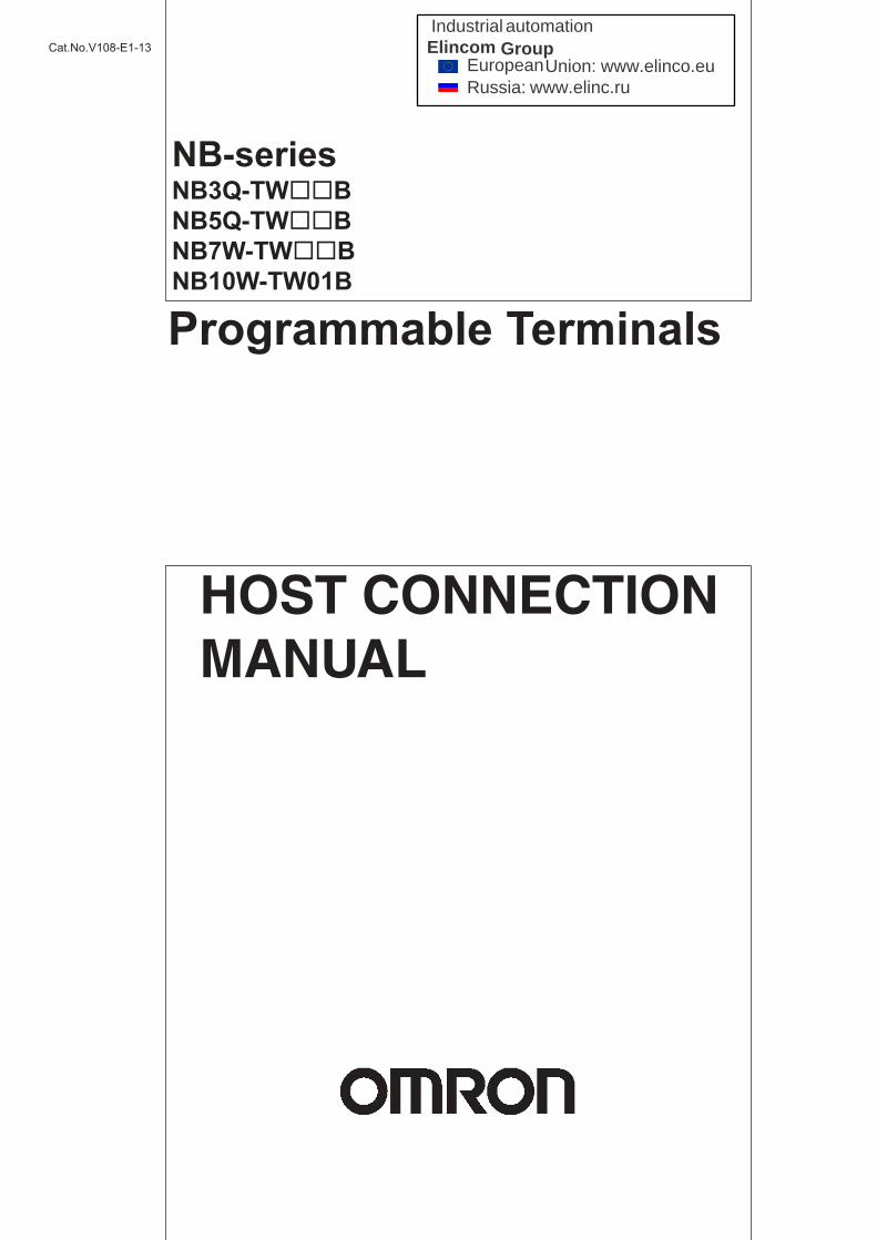
Cat.No.V108-E1-13
NB-seriesNB3Q-TWBNB5Q-TWBNB7W-TWBNB10W-TW01B
Programmable Terminals
Industrial automationElincom Group
EuropeanUnion: www.elinco.euRussia: www.elinc.ru
All rights reserved. No part of this publication may be reproduced, stored in a retrieval system, or transmitted, in any form, or by any means, mechanical, electronic, photocopying, recording, or otherwise, without the prior written permission of OMRON.
No patent liability is assumed with respect to the use of the information contained herein. Moreover, because OMRON is constantly striving to improve its high-quality products, the information contained in this manual is subject to change without notice. Every precaution has been taken in the preparation of this manual. Neverthe-less, OMRON assumes no responsibility for errors or omissions. Neither is any liability assumed for damages resulting from the use of the information contained in this publication.
• Sysmac and SYSMAC are trademarks or registered trademarks of OMRON Corporation in Japan and other countries for OMRON factory automation products.
• Microsoft, Windows, Windows Vista, and Excel are either registered trademarks or trademarks of Microsoft Corporation in the United States and other countries.
• EtherCAT® is registered trademark and patented technology, licensed by Beckhoff Automation GmbH, Germany.
• ODVA, CIP, CompoNet, DeviceNet, and EtherNet/IP are trademarks of ODVA.
• The SD and SDHC logos are trademarks of SD-3C, LLC.
Other company names and product names in this document are the trademarks or registered trademarks of their respective companies.
Trademarks
Copyrights
NOTE
Microsoft product screen shots reprinted with permission from Microsoft Corporation.

NB-seriesNB3Q-TWBNB5Q-TWBNB7W-TWBNB10W-TW01BProgrammable TerminalsHost Connection ManualRevised October 2016

1
Introduction
NB-series Programmable Terminals Host Connection Manual (V108)
Introduction
Thank you for purchasing an NB-series Programmable Terminal.
NB-Series Programmable Terminals (PTs) are designed to handle information generated in FA production sites. Be sure to understand the functions and performances etc thoroughly before using PT correctly.
This manual is intended for the following personnel, who must also have knowledge of electrical systems (an electrical engineer or the equivalent).• Personnel in charge of introducing FA systems into production facilities.• Personnel in charge of designing FA systems. • Personnel in charge of installing and connecting FA facilities.• Personnel in charge of managing FA systems and facilities
• The user must operate the product according to the performance specifications described in the operation manuals.
• Do not use the PT touch switch input functions for applications where danger to human life or serious property damage is possible, or for emergency switch applications.
• Before using the product under conditions which are not described in the manual or applying the product to nuclear control systems, railroad systems, aviation systems, vehicles, combustion systems, medical equipment, amusement machines, safety equipment, and other systems, machines and equipment that may have a serious influence on lives and property if used improperly, consult your OMRON representative.
• Make sure that the ratings and performance characteristics of the product are sufficient for the systems, machines, and equipment, and be sure to provide the systems, machines, and equipment with double safety mechanisms.
• This manual provides information for connecting and setting up an NB-Series PT. Be sure to read this manual before attempting to use the PT and keep this manual close at hand for reference during installation and operation.
Intended Audience
General Precautions
NB-series Manuals
2 NB-series Programmable Terminals Host Connection Manual (V108)
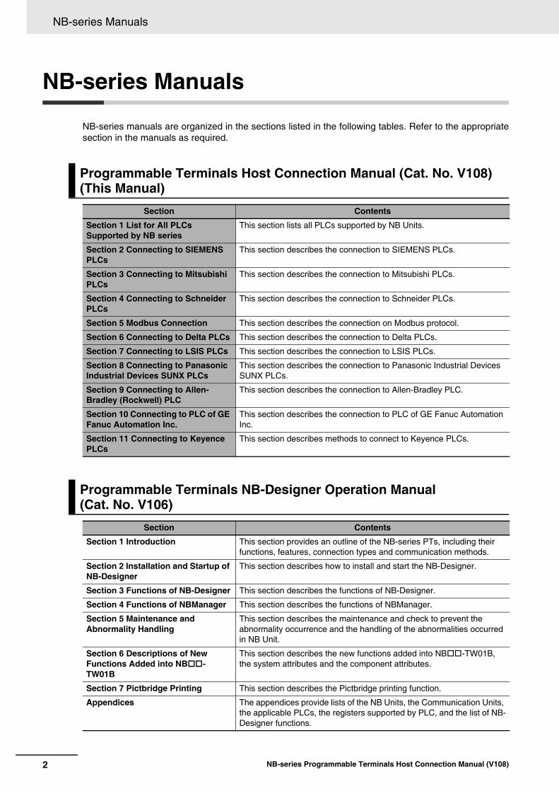
NB-series Manuals
NB-series manuals are organized in the sections listed in the following tables. Refer to the appropriatesection in the manuals as required.
Programmable Terminals Host Connection Manual (Cat. No. V108)(This Manual)
Section Contents
Section 1 List for All PLCs Supported by NB series
This section lists all PLCs supported by NB Units.
Section 2 Connecting to SIEMENS PLCs
This section describes the connection to SIEMENS PLCs.
Section 3 Connecting to Mitsubishi PLCs
This section describes the connection to Mitsubishi PLCs.
Section 4 Connecting to Schneider PLCs
This section describes the connection to Schneider PLCs.
Section 5 Modbus Connection This section describes the connection on Modbus protocol.
Section 6 Connecting to Delta PLCs This section describes the connection to Delta PLCs.
Section 7 Connecting to LSIS PLCs This section describes the connection to LSIS PLCs.
Section 8 Connecting to Panasonic Industrial Devices SUNX PLCs
This section describes the connection to Panasonic Industrial Devices SUNX PLCs.
Section 9 Connecting to Allen-Bradley (Rockwell) PLC
This section describes the connection to Allen-Bradley PLC.
Section 10 Connecting to PLC of GE Fanuc Automation Inc.
This section describes the connection to PLC of GE Fanuc Automation Inc.
Section 11 Connecting to Keyence PLCs
This section describes methods to connect to Keyence PLCs.
Programmable Terminals NB-Designer Operation Manual (Cat. No. V106)
Section Contents
Section 1 Introduction This section provides an outline of the NB-series PTs, including their functions, features, connection types and communication methods.
Section 2 Installation and Startup of NB-Designer
This section describes how to install and start the NB-Designer.
Section 3 Functions of NB-Designer This section describes the functions of NB-Designer.
Section 4 Functions of NBManager This section describes the functions of NBManager.
Section 5 Maintenance and Abnormality Handling
This section describes the maintenance and check to prevent the abnormality occurrence and the handling of the abnormalities occurred in NB Unit.
Section 6 Descriptions of New Functions Added into NB-TW01B
This section describes the new functions added into NB-TW01B, the system attributes and the component attributes.
Section 7 Pictbridge Printing This section describes the Pictbridge printing function.
Appendices The appendices provide lists of the NB Units, the Communication Units, the applicable PLCs, the registers supported by PLC, and the list of NB-Designer functions.

3
NB-series Manuals
NB-series Programmable Terminals Host Connection Manual (V108)
Programmable Terminals Setup Manual (Cat. No. V107)Section Contents
Section 1 Part Names and Functions This section describes the names and functions of the various parts of an NB Unit.
Section 2 Installing the NB Unit and Connecting Peripheral Devices
This section describes the methods used to install the NB Unit and connect peripheral devices.
Section 3 System Setting Mode This section describes the System Setting Mode.
Section 4 Calibrate Mode This section describes the Calibrate Mode.
Appendices The appendices provide information on specifications, dimensions, wirings, and lists of the NB Units, the applicable PLCs and options.
Programmable Terminals Startup Guide Manual (Cat. No. V109)Section Contents
Section 1 NB Overview This section provide specifications of the NB Unit, describes its names and functions of the various parts.
Section 2 System Design This section describes the manual structure, takes NB7W as an example to introduce the operation procedures of the NB system.
Section 3 Installation and Wiring This section describes how to install and wire the NB Unit.
Section 4 Screen Creation This section describes how to create a demonstration project through NB-Designer.
Section 5 Run This section describes how to start running at the Host side and prepare to send screen data to NB7W.
Section 6 Maintenance and Troubleshooting
This section describes the maintenance and inspection methods for preventing errors occurring, and troubleshooting measures when errors occur.
WARNING
Failure to read and understand the information provided in this manual may result in personal injury or death, damage to the product, or product failure.Please read each section in its entirety and be sure you understand the information provided in the section and related sections before attempting any of the procedures or operations given.

Manual Structure
4 NB-series Programmable Terminals Host Connection Manual (V108)
Manual Structure
The following page structure and icons are used in this manual.
Special information in this manual is classified as follows:
Page Structure and Icons
Special Information
2-3
2 Installing the NB Unit and Connecting Peripheral Devices
NB-series Programmable Terminals Setup Manual(V107)
2-1 Installin
g th
e NB
Un
it
2
2-1-2 Installation onto the Operation P
anel
Install the NB Unit by embedding it into the operation panel.
Use the metal kit and tool (a crosshead screwdriver) supplied with the Unit for installation.
Proceed the installation following the procedures below.
1 Panel cutout with dimensions is shown below. Fit the NB Unit into the panel from the front side.
2 As follows, insert panel fixators at the locations indicated by red box around the back of the NB Unit.
Insert the hooks of positioners into the square holes on the Unit to hold the fixators properly, and tighten the screws firmly with the screwdriver.
NB5Q/NB7W-TW��B
Precautions for Safe Use
• When operating on the operation panel, make sure to keep metal particles from entering the Unit.
The mounting panel must be between 1.6 and 4.8 mm thick. The NB Unit must be installed in a control panel.
For the sake of waterproof and dustproof, all the fixators must be evenly tightened to a torque of 0.5~0.6 Nm. If the tightening torque exceeds the specified value, or the tightening is not even, deformation of the front panel may occur.
Make sure that the operation panel is clean, unbent, and strong enough for the installation process.
2-1-2 Installation onto the Operation Panel
Models Opening Dimension (W H mm)
NB3Q-TW00B/TW01B 119.0(+0.5/-0) 93.0(+0.5/-0)
NB5Q-TW00B/TW01B 172.4(+0.5/-0) 131.0(+0.5/-0)
NB7W-TW00B/TW01B 191.0(+0.5/-0) 137.0(+0.5/-0)
NB10W-TW01B 258.0(+0.5/-0) 200.0(+0.5/-0)
Opening dimensions
Width
Height
Level 1 headingLevel 2 headingLevel 3 heading
Step in a procedure
Manual name
Special Information (See below.)
Level 3 heading
Page tab
Gives the current headings.
Indicates a step in a procedure.
Gives the number of the section.
This illustration is provided only as a sample and may not literally appear in this manual.
Icons are used to indicate precautions and additional information.
Precautions for Safe UsePrecautions on what to do and what not to do to ensure using the product safely.
Precautions for Correct UsePrecautions on what to do and what not to do to ensure proper operation and performance.
Additional InformationAdditional information to increase understanding or make operation easier.

5
Terminology
NB-series Programmable Terminals Host Connection Manual (V108)
Terminology
The following terminology is used in this manual.
Terms Descriptions
NB Unit Indicates the main Unit of the products in the OMRON NB Series of Programmable Terminal.
NB Series Indicates products in the OMRON NB Series of Programmable Terminal.In this manual, unless otherwise specified, NB Series is taken as the subject concerned.
PLC Indicates a Programmable Controller.
CP Series Indicates the following products in the OMRON CP Series of Programmable Controllers: CP1H, CP1L, CP1E
CS/CJ Series Indicates the following products in the OMRON CS/CJ Series of Programmable Controllers: CS1G, CS1H, CS1G-H, CS1H-H, CJ1G, CJ1M, CJ2M, CJ2H
NJ/NX Series Indicates the following OMRON SYSMAC NJ Series of Programmable Controllers: NJ501, NJ301, NX1P2
C Series Indicates the following products in the OMRON C Series of Programmable Controllers: C200HX(-Z), C200HG(-Z), C200HE(-Z), CQM1, CQM1H, CPM1A, CPM2A, CPM2C
Serial Communication Unit
Indicates a Serial Communication Unit for an OMRON SYSMAC CS/CJ-Series PLC.
Serial Communication Board
Indicates a Serial Communication Board for an OMRON SYSMAC CS/CJ-Series PLC.
Communication Board Indicates a Communication Board for an OMRON C200HX/HG/HE(-Z) PLC.
CPU Unit Indicates a CPU Unit in the OMRON CP, CS/CJ or SYSMAC C Series of Programmable Controllers.
NB-Designer Indicates the OMRON NB-Designer.
Host Indicates the PLC and other units functioning as the control devices for NB-Series Units.
PT Indicates an OMRON Programmable Terminal.

Terminology
6 NB-series Programmable Terminals Host Connection Manual (V108)

7
CONTENTS
NB-series Programmable Terminals Host Connection Manual (V108)
CONTENTS
Introduction............................................................................................................... 1
NB-series Manuals.................................................................................................... 2
Manual Structure ...................................................................................................... 4
Terminology .............................................................................................................. 5
Terms and Conditions Agreement ........................................................................ 11
Safety Precautions ................................................................................................. 13
Precautions for Safe Use ....................................................................................... 16
Precautions for Correct Use .................................................................................. 18
Conformance to EC Directives .............................................................................. 19
Related Manuals ..................................................................................................... 20
Sec. 1 List for All PLCs Supported by NB Series........................... 1-1
1-1 Lists for Supported PLC ......................................................................................................... 1-21-2 Definition and Description of Serial Port COM ..................................................................... 1-7
Sec. 2 Connecting to SIEMENS PLCs ............................................. 2-1
2-1 Serial Port and Ethernet.......................................................................................................... 2-22-1-1 Serial Port ................................................................................................................................... 2-2
2-1-2 Ethernet ...................................................................................................................................... 2-2
2-2 Communication Parameters and Cable Fabrication ............................................................ 2-32-2-1 Serial Port ................................................................................................................................... 2-3
2-2-2 Ethernet ...................................................................................................................................... 2-3
2-3 Communication Parameter Setting........................................................................................ 2-42-3-1 When Using SIEMENS S7-200 Communication Protocol .......................................................... 2-4
2-3-2 When Using SIEMENS S7-300/400 (PC Adapter Direct) Communication Protocol................... 2-5
2-3-3 SIEMENS S7-200 (SMART) Ethernet (TCP Slave).................................................................... 2-8
2-3-4 SIEMENS S7-300 Ethernet (TCP Slave).................................................................................. 2-17
2-3-5 SIEMENS S7-1200 Ethernet (TCP Slave)................................................................................ 2-23
2-4 Supported Registers ............................................................................................................. 2-272-4-1 SIEMENS S7-200..................................................................................................................... 2-27
2-4-2 SIEMENS S7-300/400 (PC Adapter Direct).............................................................................. 2-28
2-4-3 SIEMENS S7-200 (Smart) Ethernet (TCP Slave)..................................................................... 2-28
2-4-4 SIEMENS S7-300 Ethernet (TCP Slave).................................................................................. 2-29
2-4-5 SIEMENS S7-1200 Ethernet (TCP Slave)................................................................................ 2-30
2-5 Cable Fabrication .................................................................................................................. 2-31

CONTENTS
8 NB-series Programmable Terminals Host Connection Manual (V108)
Sec. 3 Connecting to Mitsubishi PLCs............................................ 3-1
3-1 Serial Port and Ethernet.......................................................................................................... 3-23-1-1 Serial Port ................................................................................................................................... 3-2
3-1-2 Ethernet....................................................................................................................................... 3-3
3-2 Communication Setting and Cable Connection ................................................................... 3-43-2-1 Serial Port ................................................................................................................................... 3-4
3-2-2 Ethernet....................................................................................................................................... 3-5
3-3 Communication Setting .......................................................................................................... 3-63-3-1 When Using Mitsubishi FX1S, Mitsubishi FX1N/2N/3G and Mitsubishi FX3U Communication
Protocols ..................................................................................................................................... 3-6
3-3-2 When Using Mitsubishi FX-485ADP/485BD/232BD (Multi-station) Communication Protocols... 3-8
3-3-3 When Using FX2N-10GM/20GM Communication Protocol ...................................................... 3-11
3-3-4 When Using Mitsubishi Q00J (CPU Port) Communication Protocol ......................................... 3-12
3-3-5 When Using Mitsubishi Q series (CPU Port) Communication Protocol .................................... 3-12
3-3-6 When Using Mitsubishi Q06H Communication Protocol ........................................................... 3-13
3-3-7 When Using Mitsubishi Q_QnA (Link Port) Communication Protocol....................................... 3-14
3-3-8 When Using Mitsubishi FX Series Ethernet(TCP Slave) Communication Protocol .................. 3-19
3-3-9 When Using Mitsubishi QnA 3EBin Ethernet (TCP Slave) Communication Protocol ............... 3-22
3-3-10 When Using Mitsubishi QJ71E71 EtherNet Slave Communication Protocol ............................ 3-25
3-4 Supported Registers ............................................................................................................. 3-283-5 Cable Fabrication .................................................................................................................. 3-34
Sec. 4 Connecting to Schneider PLCs ............................................ 4-1
4-1 Serial Port Communication .................................................................................................... 4-24-2 Communication Parameters and Cable Fabrication ............................................................ 4-34-3 Communication Parameter Setting........................................................................................ 4-44-4 Supported Registers ............................................................................................................. 4-134-5 Cable Fabrication .................................................................................................................. 4-14
Sec. 5 Modbus Connection .............................................................. 5-1
5-1 Serial Port and Ethernet.......................................................................................................... 5-25-2 Communication Parameters and Cable Fabrication ............................................................ 5-35-3 Communication Parameter Setting........................................................................................ 5-45-4 Supported Registers ............................................................................................................... 5-75-5 Cable Fabrication .................................................................................................................... 5-95-6 Modbus Protocol .................................................................................................................. 5-10
5-6-1 Introduction to Modbus Protocol ............................................................................................... 5-10
5-6-2 When NB adopts Modbus TCP protocol (Master/Slave mode)................................................. 5-11
5-7 Example of NB as Modbus Slave ......................................................................................... 5-125-8 Example of connection using Modbus TCP protocol ........................................................ 5-155-9 Example of E5CC/E5EC, 3G3MX2 connection using Modbus RTU Extend Protocol ..... 5-165-10 Example of Power PMAC Motion Controller using Modbus TCP Slave Protocol............ 5-18

9
CONTENTS
NB-series Programmable Terminals Host Connection Manual (V108)
Sec. 6 Connecting to Delta PLCs..................................................... 6-1
6-1 Serial Port Communication .................................................................................................... 6-26-2 Communication Parameters and Cable Fabrication ............................................................ 6-36-3 Communication Parameter Setting........................................................................................ 6-46-4 Supported Registers ............................................................................................................... 6-66-5 Cable Fabrication .................................................................................................................... 6-7
Sec. 7 Connecting to LSIS PLCs...................................................... 7-1
7-1 Serial Port Communication .................................................................................................... 7-27-2 Communication Parameters and Cable Fabrication ............................................................ 7-37-3 Communication Parameter Setting........................................................................................ 7-47-4 Supported Registers ............................................................................................................... 7-97-5 Cable Fabrication .................................................................................................................. 7-11
Sec. 8 Connecting to Panasonic Industrial Devices SUNX PLCs............................................................................. 8-1
8-1 Serial Port Communication .................................................................................................... 8-28-2 Communication Parameters and Cable Fabrication ............................................................ 8-38-3 Communication Parameter Setting........................................................................................ 8-48-4 Supported Registers ............................................................................................................... 8-58-5 Cable Fabrication .................................................................................................................... 8-6
Sec. 9 Connecting to Allen-Bradley (Rockwell) PLC ..................... 9-1
9-1 Serial Port Communication and Ethernet ............................................................................. 9-29-1-1 Serial Port ................................................................................................................................... 9-2
9-1-2 Ethernet ...................................................................................................................................... 9-3
9-2 Communication Parameters and Cable Fabrication ............................................................ 9-49-2-1 Serial Port ................................................................................................................................... 9-4
9-2-2 Ethernet ...................................................................................................................................... 9-4
9-3 Communication Parameter Setting........................................................................................ 9-59-3-1 When Using AB SLC500/MicroLogix Series (DF1) Protocol ...................................................... 9-5
9-3-2 When Using AB CompactLogix/ControlLogix Series (DF1) Protocol.......................................... 9-7
9-3-3 AB MicroLogix Series Ethernet(TCP Slave) ............................................................................. 9-11
9-4 Supported Registers ............................................................................................................. 9-149-5 Cable Fabrication .................................................................................................................. 9-16
Sec. 10 Connecting to PLC of GE Fanuc Automation Inc. ............ 10-1
10-1 Serial Port Communication .................................................................................................. 10-210-2 Serial Port Communication Parameters and Cable Fabrication ....................................... 10-310-3 Serial Port Communication Parameter Setting................................................................... 10-410-4 Supported Registers ............................................................................................................. 10-710-5 Cable Fabrication .................................................................................................................. 10-8

CONTENTS
10 NB-series Programmable Terminals Host Connection Manual (V108)
Sec. 11 Connecting to Keyence PLCs............................................. 11-1
11-1 Serial Port and the Ethernet ................................................................................................. 11-211-2 Communication Setting and Cable Connection ................................................................. 11-311-3 Communication Setting ........................................................................................................ 11-4
11-3-1 When Using Keyence KV-3000 Communication Protocol ........................................................ 11-4
11-3-2 When Using Keyence KV-5000 EtherNetSlave Communication Protocol ................................ 11-5
11-4 Supported Registers ............................................................................................................. 11-711-5 Cable Connection .................................................................................................................. 11-8
Sec. 12 Connecting to OMRON Safety Controller .......................... 12-1
12-1 Serial Port............................................................................................................................... 12-212-2 Communication Parameters and Cable Fabrication .......................................................... 12-312-3 Communication Parameter Setting...................................................................................... 12-4
12-3-1 When using OMRON G9SP Communication Protocol.............................................................. 12-4
12-4 Supported Registers ............................................................................................................. 12-612-5 Cable Connection .................................................................................................................. 12-7
Revision History........................................................................................................1
11
Terms and Conditions Agreement
NB-series Programmable Terminals Host Connection Manual (V108)
Terms and Conditions Agreement
Exclusive WarrantyOmron’s exclusive warranty is that the Products will be free from defects in materials and workman-ship for a period of twelve months from the date of sale by Omron (or such other period expressed inwriting by Omron). Omron disclaims all other warranties, express or implied.
LimitationsOMRON MAKES NO WARRANTY OR REPRESENTATION, EXPRESS OR IMPLIED, ABOUTNON-INFRINGEMENT, MERCHANTABILITY OR FITNESS FOR A PARTICULAR PURPOSE OFTHE PRODUCTS. BUYER ACKNOWLEDGES THAT IT ALONE HAS DETERMINED THAT THEPRODUCTS WILL SUITABLY MEET THE REQUIREMENTS OF THEIR INTENDED USE.
Omron further disclaims all warranties and responsibility of any type for claims or expenses basedon infringement by the Products or otherwise of any intellectual property right.
Buyer RemedyOmron’s sole obligation hereunder shall be, at Omron’s election, to (i) replace (in the form originallyshipped with Buyer responsible for labor charges for removal or replacement thereof) the non-com-plying Product, (ii) repair the non-complying Product, or (iii) repay or credit Buyer an amount equalto the purchase price of the non-complying Product; provided that in no event shall Omron beresponsible for warranty, repair, indemnity or any other claims or expenses regarding the Productsunless Omron’s analysis confirms that the Products were properly handled, stored, installed andmaintained and not subject to contamination, abuse, misuse or inappropriate modification. Return ofany Products by Buyer must be approved in writing by Omron before shipment. Omron Companiesshall not be liable for the suitability or unsuitability or the results from the use of Products in combi-nation with any electrical or electronic components, circuits, system assemblies or any other materi-als or substances or environments. Any advice, recommendations or information given orally or inwriting, are not to be construed as an amendment or addition to the above warranty.
See http://www.omron.com/global/ or contact your Omron representative for published information.
OMRON COMPANIES SHALL NOT BE LIABLE FOR SPECIAL, INDIRECT, INCIDENTAL, OR CONSEQUENTIAL DAMAGES, LOSS OF PROFITS OR PRODUCTION OR COMMERCIAL LOSS IN ANY WAY CONNECTED WITH THE PRODUCTS, WHETHER SUCH CLAIM IS BASED IN CONTRACT, WARRANTY, NEGLIGENCE OR STRICT LIABILITY.
Further, in no event shall liability of Omron Companies exceed the individual price of the Product on which liability is asserted.
Warranty, Limitations of Liability
Warranties
Limitation on Liability; Etc

Terms and Conditions Agreement
12 NB-series Programmable Terminals Host Connection Manual (V108)
Omron Companies shall not be responsible for conformity with any standards, codes or regulations which apply to the combination of the Product in the Buyer’s application or use of the Product. At Buyer’s request, Omron will provide applicable third party certification documents identifying ratings and limitations of use which apply to the Product. This information by itself is not sufficient for a complete determination of the suitability of the Product in combination with the end product, machine, system, or other application or use. Buyer shall be solely responsible for determining appropriateness of the particular Product with respect to Buyer’s application, product or system. Buyer shall take application responsibility in all cases.
NEVER USE THE PRODUCT FOR AN APPLICATION INVOLVING SERIOUS RISK TO LIFE OR PROPERTY WITHOUT ENSURING THAT THE SYSTEM AS A WHOLE HAS BEEN DESIGNED TO ADDRESS THE RISKS, AND THAT THE OMRON PRODUCT(S) IS PROPERLY RATED AND INSTALLED FOR THE INTENDED USE WITHIN THE OVERALL EQUIPMENT OR SYSTEM.
Omron Companies shall not be responsible for the user’s programming of a programmable Product, or any consequence thereof.
Data presented in Omron Company websites, catalogs and other materials is provided as a guide for the user in determining suitability and does not constitute a warranty. It may represent the result of Omron’s test conditions, and the user must correlate it to actual application requirements. Actual performance is subject to the Omron’s Warranty and Limitations of Liability.
Product specifications and accessories may be changed at any time based on improvements and other reasons. It is our practice to change part numbers when published ratings or features are changed, or when significant construction changes are made. However, some specifications of the Product may be changed without any notice. When in doubt, special part numbers may be assigned to fix or establish key specifications for your application. Please consult with your Omron’s representative at any time to confirm actual specifications of purchased Product.
Information presented by Omron Companies has been checked and is believed to be accurate; however, no responsibility is assumed for clerical, typographical or proofreading errors or omissions.
Application Considerations
Suitability of Use
Programmable Products
Disclaimers
Performance Data
Change in Specifications
Errors and Omissions

13
Safety Precautions
NB-series Programmable Terminals Host Connection Manual (V108)
Safety Precautions
The following notation is used in this manual to provide precautions required to ensure safe usage of the product. The safety precautions that are provided are extremely important to safety. Always read and heed the information provided in all safety precautions.
Notation Used for Safety Information
Symbols
The circle and slash symbol indicates operations that you must not do.
The specific operation is shown in the circle and explained in text.
This example indicates prohibiting disassembly.
The triangle symbol indicates precautions (including warnings).
The specific operation is shown in the triangle and explained in text.
This example indicates a general precaution.
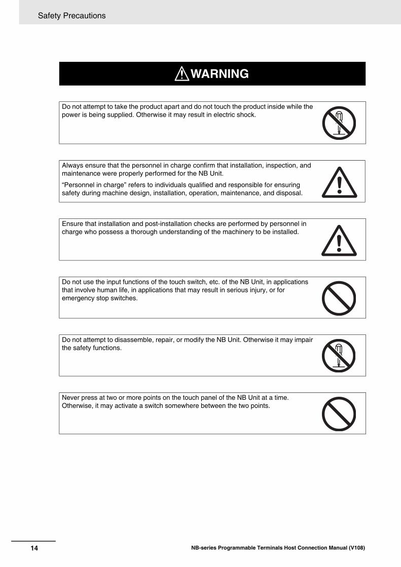
WARNINGIndicates an imminently hazardous situation which, if not avoided, will result in death or serious injury. Additionally, there may be severe property damage.
Precautions for Safe UseIndicates precautions on what to do and what not to do to ensure using the product safely.
Precautions for Correct UseIndicates precautions on what to do and what not to do to ensure proper operation and performance.
Note Indicates suggestive information and precautions on operation of the product.
Safety Precautions
14 NB-series Programmable Terminals Host Connection Manual (V108)
Do not attempt to take the product apart and do not touch the product inside while the power is being supplied. Otherwise it may result in electric shock.
Always ensure that the personnel in charge confirm that installation, inspection, and maintenance were properly performed for the NB Unit.
“Personnel in charge” refers to individuals qualified and responsible for ensuring safety during machine design, installation, operation, maintenance, and disposal.
Ensure that installation and post-installation checks are performed by personnel in charge who possess a thorough understanding of the machinery to be installed.
Do not use the input functions of the touch switch, etc. of the NB Unit, in applications that involve human life, in applications that may result in serious injury, or for emergency stop switches.
Do not attempt to disassemble, repair, or modify the NB Unit. Otherwise it may impair the safety functions.
Never press at two or more points on the touch panel of the NB Unit at a time. Otherwise, it may activate a switch somewhere between the two points.
WARNING

15
Safety Precautions
NB-series Programmable Terminals Host Connection Manual (V108)
Precaution
Wiring
TIn the case of the NB Series, when grounding the positive terminal of power supply of 24 V to the NB, do not ground functional grounding terminal at NB side. Some functions of a PC connected to the NB may cause a short circuit and the NB Unit may cause damage.• Caution:
Depending on the types of PC, SG terminals of RS-232C port or USB port and contour of connector can be connected. As the contour of tool port of the NB and the functional grounding terminal are not insulated, they are connected. Therefore, connecting the PC allows GND terminal and functional grounding terminal of the NB to be connected. If the power supply of 24V to the NB is grounded pos-itively, grounding the functional grounding terminal allows a short circuit as shown in the diagram below and may result in damage.
Test Function
The Test Function is performed on PC so that a problem may occur affected by the timing or the differences with communication route. When the test function is performed, considering possible unexpected circumstances on PC, confirm that any dangerous event will not occur beforehand.
Caution
NB
SGSG
24V
0V GND
Power Supply
Grounding Grounding
Functional Grounding
Cable
Contour Contour
PC
Do not ground the functional grounding.

Precautions for Safe Use
16 NB-series Programmable Terminals Host Connection Manual (V108)
Precautions for Safe Use
• When unpacking the NB Units and the peripheral devices, check carefully for any external scratches or other damages. Also, shake the Units gently and check for any abnormal sound.
• The NB Unit must be installed in a control panel.• The mounting panel must be between 1.6 and 4.8 mm thick. Tighten the Mounting Brackets evenly to a
torque of between 0.5 and 0.6 Nm to maintain water and dust resistance. If the tightening torque exceeds the specified value, or the tightening is not even, deformation of the front panel may occur. What is more, make sure the panel is not dirty or warped and that it is strong enough to hold the Units.
• Do not let metal particles enter the Units when preparing the panel.• Do not connect an AC power supply to the DC power terminals.• Use a DC power with a slight voltage fluctuation and reinforced or double insulation, and that will
provide a stable output even if the input is momentarily interrupted for 10 ms.Rated Power Supply Voltage: DC 24 V (Allowable range DC 20.4 ~ 27.6 V)
• Do not perform a dielectric voltage test.• Before connecting the power supply to the NB unit, mount the cable on the terminal block. Make the
connection by using terminal screws crimping on a twisted-pair cable with a crimping range of 12~26 AWG, and only 6.5 mm of insulation peel of the cable needs to be peeled off. Tighten the terminal screws at a torque of between 0.3 and 0.5 Nm. Make sure the screws are properly tightened. Do not use the terminal block of NB3Q-TWB for other models. NB3Q-TWB has different pin definitions on the terminal block.
• To prevent malfunctions caused by noise, ground the Unit correctly.• Do not touch the packaging part of the circuit board with your bare hands. Discharge any static
electricity from your body before handling the board.• When using the No. 6 pin of the serial communication port COM1 connector for a voltage of DC+5V,
make sure the supply equipment’s current capacity is below 250mA before using it. The DC+5V voltage output of the NB unit is +5V±5%, and the maximum current is 250mA. (The serial communication port COM1 of NB3Q-TWB is unable to output the current.)
• Turn OFF the power supply before connecting or disconnecting cables.• Always keep the connector screws firmly tightened after the communication cable is connected.• The maximum tensile load for cables is 30 N. Do not apply loads greater than this. • Confirm the safety of the system before turning ON or OFF the power supply, or pressing the reset button.• The whole system may stop depending on how the power supply is turned ON or OFF. Turn ON/OFF
the power supply according to the specified procedure.• Reset by pressing the reset button, or restart the power supply, once the DIP switch settings are changed.• To ensure the system’s safety, make sure to incorporate a program that can confirm the normal
functionality of the NB Unit before running the system.• Start actual system application only after sufficiently checking screen data, macros and the operation
of the program at the host side.• Do not press the touch panel with a force greater than 30 N.• Do not use hard or pointed objects to operate or scrub the screen, otherwise, the surface of the
screen may be damaged.• Confirm the safety of the system before pressing the touch panel.• Signals from the touch switches may not be input if the touch switches are pressed consecutively at
high speed. Confirm each input before proceeding to the next one.• Do not accidentally press the touch panel when the backlight is not lit or when the display does not
appear. Make sure of the safety of the system before pressing the touch panel. • To use numeric input functions safely, always make maximum and minimum limit settings. • Before initializing screen data, confirm that existing data is backed up at the NB-Designer.
17
Precautions for Safe Use
NB-series Programmable Terminals Host Connection Manual (V108)
• When changing the password with the screen, do not reset or turn OFF the power supply until writing is finished. Failure to save the password may cause the screen to fail to function.
• When using an equipment monitor, confirm the safety of the system before carrying out the following operations:• Changing monitor data.• Changing operation mode.• Forced set/reset.• Changing the current value or the set value.
• Do not connect a USB connector to any device that is not applicable.• When connecting the equipment with the USB HOST connector, make sure the supply equipment's
current capacity is below 150mA before using it. The DC+5V voltage output of the NB Unit is +5V±5%, and the maximum current is 150mA.
• Before connecting a USB connector to a device, make sure that the device is free of damage.• Commercially available and the recommended USB HUBs are different from the general
specifications of the NB Unit. The unit may not function well in an environment subject to noise, static electricity. Therefore, when using a USB HUB, employ sufficient noise and static electricity insulation measures, or install it at a site free of noise or static electricity.
• While uploading or downloading screen data or system programs, do not perform the following operations that may corrupt the screen data or the system program:• Turning OFF the power supply of the NB Unit.• Pressing the PT’s reset switch.
• Dispose of the Units and batteries according to local ordinances as they apply.
• Do not dispose the product into a fire. Doing so may cause the damage with the battery or electronic components.• Do not apply an impact with the lithium cell, charge it, dispose it into a fire, or heat it. Doing either of
them may cause an ignition or a bursting.• When exporting products with lithium primary batteries containing perchlorate at 6ppb or above to or
delivering them through California, USA, the following precautionary measures have to be publicized.Perchlorate material - applicable through special processing. Refer tohttp://www.dtsc.ca.gov/hazardouswaste/perchlorate. NB-Series products contain lithium primary batteries. When exporting products containing this kind of batteries to or delivering them through California, USA, label all the product packages as well as the appropriate delivery packages.
• Do not use benzene, paint thinner, or other volatile solvents, and do not use chemically treated cloths.• Do not dispose the Units together with general waste at waste yards. When disposing them, follow
the related local ordinances or rules.• Cannot replace the backlight lamp inside the NB Unit. • Deterioration over time can cause the touch points to move. Calibrate the touch panel periodically.• Water and oil resistance will be lost if the front sheet is torn or is peeling off. Do not use the Unit, if the
front sheet is torn or is peeling off. • The rubber packing will deteriorate, shrink, or harden depending on the operating environment.
Inspect the rubber packing periodically. • The communication cables of the COM1 and COM2 connectors are not interchangeable. Confirm the
pins of the ports before carrying out communications. (NB3Q-TWB only has COM1.)• Periodically check the installation conditions in applications where the PT is subject to contact with oil or water.• Do not perform the following operations during the communication of the USB memory:
• Turning off the power supply of the NB Unit. • Pressing the Reset button on the NB Unit. • Removing the USB memory.
• Do not use the USB memory in the environment subject to strong vibration.

Precautions for Correct Use
18 NB-series Programmable Terminals Host Connection Manual (V108)
Precautions for Correct Use
• Do not install the unit in any of the following locations:Locations subject to severe changes in temperatureLocations subject to temperatures or humidity outside the range specified in the specificationsLocations subject to condensation as the result of high humidityLocations subject to corrosive or flammable gasesLocations subject to strong shock or vibrationLocations outdoors subject to direct wind and rainLocations subject to strong ultraviolet lightLocations subject to dustLocations subject to direct sunlightLocations subject to splashing oil or chemicals
• Take appropriate and sufficient countermeasures when installing systems in the following locations:Locations subject to static electricity or other forms of noiseLocations subject to strong electric field or magnetic fieldLocations close to power supply linesLocations subject to possible exposure to radioactivity
• Precautions for software:The update, restoration, uninstall and reinstallation of software in running status is prohibited in order to guarantee the correct use of the product.

19
Conformance to EC Directives
NB-series Programmable Terminals Host Connection Manual (V108)
Conformance to EC DirectivesNB-Series Programmable Terminals are EMC compliant.
OMRON products are electronic devices that are incorporated in machines and manufacturing installations. OMRON PTs conform to the related EMC Directives (see note) so that the devices and machines into which they are built can more easily conform to EMC Directives. The actual products have been through inspections and are completely in accordance with EMC directives. However, when they are built into customers’ systems, whether the systems also comply with these Directives is up to the customers for further inspection.
EMC-related performance of OMRON PTs will vary depending on the configuration, wiring, and other conditions of the OMRON equipment or control panel. The customer must, therefore, perform final checks to confirm that the overall machine or device conforms to EMC standards.Note The applicable EMC (Electromagnetic Compatibility) standards are as follows:
EMS (Electromagnetic sensitivity): EN61131-2: 2007EMI (Electromagnetic Interference): EN61131-2: 2007
NB-Series Programmable Terminals are EC compliant. Heed the following precautions in order to ensure that the customer’s overall machine and device conform to EC Directives.
1 The PT must be installed in a control panel.
2 You must use reinforced insulation or double insulation for the DC power supply and the DC power supply must have minimal voltage fluctuations and provide a stable output even if the power supply input is interrupted for 10 ms.
3 The PTs conform to the standard EN 61131-2, but radiated emission characteristics (10m regulations) may vary depending on the configuration of the control panel used, other devices connected to the control panel, wiring, and other conditions. You must therefore confirm that the overall machine or equipment complies with EC Directives.
4 This is a Class A product (Product for industry purpose). It may cause radio interference in residential areas, in which case the user may be required to take adequate measures to reduce interference.
Observe the following precaution if you use NB-series Programmable Terminals in Korea.
Class A Device (Broadcasting Communications Device for Office Use)
This device obtained EMC registration for office use (Class A), and it is intended to be used inplaces other than homes.
Sellers and/or users need to take note of this.
Concepts
Conformance to EC Directives
Conformance to KC Standards

Related Manuals
20 NB-series Programmable Terminals Host Connection Manual (V108)
Related Manuals
The related manuals are as follows:
Devices and Software Manual Name Manual No.NB series NB Series NB-Designer Operation Manual V106
NB Series Setup Manual V107
NB Series Host Connection Manual (This manual) V108
NB Series Startup Guide V109
PLC SYSMAC CP Series CP1L CPU Unit Operation Manual W462
SYSMAC CP Series CP1H/L CPU Unit Programming Manual W451
SYSMAC CP Series CP1H CPU Unit Operation Manual W450
SYSMAC CP Series CP1E CPU Unit Hardware USER’S Manual
W479
SYSMAC CP Series CP1E CPU Unit Software USER’S Manual
W480
SYSMAC C200HX/HG/HE(-E/-ZE) Installation Guide W302
SYSMAC C200HX/HG/HE Operation Manual W303
SYSMAC C200HX/HG/HE(-ZE) Operation Manual W322
SYSMAC CPM1A Operation Manual W317
SYSMAC CPM2A Operation Manual W352
SYSMAC CPM1/CPM1A/CPM2A/CPM2C/SRM1(-V2) Programming Manual
W353
SYSMAC CPM2C Operation Manual W356
SYSMAC CS1 Series CS1G/H Operation Manual W339
SYSMAC CS/CJ Series Serial Communications Boards and Serial Communications Units Operation Manual
W336
SYSMAC CJ Series CJ1G/H(-H) CJ1M CJ1G Operation Manual
W393
SYSMAC CS/CJ Series Programming Manual W394
SYSMAC CS/CJ Series INSTRUCTIONS Reference Manual W340
SYSMAC CS/CJ Series Programming Consoles Operation Manual
W341
SYSMAC CS/CJ Series Communications Commands Reference Manual
W342
SYSMAC CJ Series CJ2 CPU Unit Hardware USER’S Manual W472
SYSMAC CJ Series CJ2 CPU Unit Software USER’S Manual W473
SYSMAC CS/CJ Series CS1W/CJ1W-ETN21 (100Base-TX) Ethernet Units Operation Manual Construction of Networks
W420
SYSMAC CS/CJ Series CS1W/CJ1W-ETN21 (100Base-TX) Ethernet Units Operation Manual Construction of Applications
W421
SYSMAC CS/CJ Series CS1W/CJ1W-EIP21 (100Base-TX) EtherNet/IPTM Units Operation Manual
W465
SYSMAC CP Series CP1L-EL/EM CPU Unit Operation Manual W516
NJ Series CPU Unit Hardware USER’S Manual W500
NJ/NX Series CPU Unit Software USER’S Manual W501
NJ/NX Series CPU Unit Built-in EtherNet/IPTM Port USER’S Manual
W506
NJ/NX Series Troubleshooting Manual W503
NX-Series NX1P2 CPU Unit Hardware User's Manual W578
NX-Series NX1P2 CPU Unit Built-in I/O and Option Board User's Manual
W579

21
Related Manuals
NB-series Programmable Terminals Host Connection Manual (V108)
Safety Controller G9SP Series Safety Controller OPERATION MANUAL Z922
External Tool CX-Programmer Ver.9. Operation Manual W446
Sysmac Studio Version 1 Operation Manual W504
Devices and Software Manual Name Manual No.

Related Manuals
22 NB-series Programmable Terminals Host Connection Manual (V108)

1-1NB-series Programmable Terminals Host Connection Manual (V108)
1
This section lists all PLCs supported by NB Series.
1-1 Lists for Supported PLC . . . . . . . . . . . . . . . . . . . . . . . . . . . . . . . . . . . . . . . . 1-2
1-2 Definition and Description of Serial Port COM . . . . . . . . . . . . . . . . . . . . . . 1-7
List for All PLCs Supported by NB Series
1 List for All PLCs Supported by NB Series
1-2 NB-series Programmable Terminals Host Connection Manual (V108)
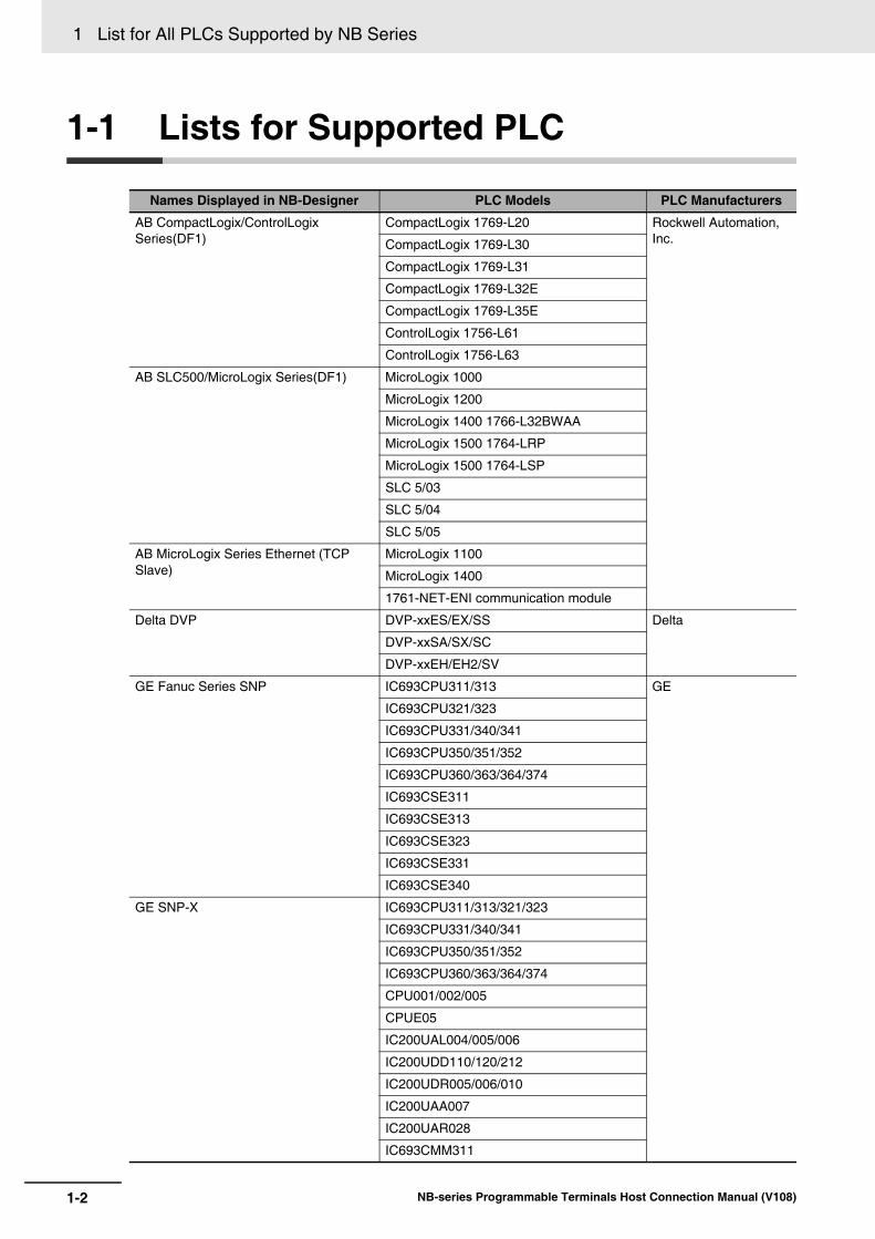
1-1 Lists for Supported PLC
Names Displayed in NB-Designer PLC Models PLC Manufacturers
AB CompactLogix/ControlLogix Series(DF1)
CompactLogix 1769-L20 Rockwell Automation, Inc.CompactLogix 1769-L30
CompactLogix 1769-L31
CompactLogix 1769-L32E
CompactLogix 1769-L35E
ControlLogix 1756-L61
ControlLogix 1756-L63
AB SLC500/MicroLogix Series(DF1) MicroLogix 1000
MicroLogix 1200
MicroLogix 1400 1766-L32BWAA
MicroLogix 1500 1764-LRP
MicroLogix 1500 1764-LSP
SLC 5/03
SLC 5/04
SLC 5/05
AB MicroLogix Series Ethernet (TCP Slave)
MicroLogix 1100
MicroLogix 1400
1761-NET-ENI communication module
Delta DVP DVP-xxES/EX/SS Delta
DVP-xxSA/SX/SC
DVP-xxEH/EH2/SV
GE Fanuc Series SNP IC693CPU311/313 GE
IC693CPU321/323
IC693CPU331/340/341
IC693CPU350/351/352
IC693CPU360/363/364/374
IC693CSE311
IC693CSE313
IC693CSE323
IC693CSE331
IC693CSE340
GE SNP-X IC693CPU311/313/321/323
IC693CPU331/340/341
IC693CPU350/351/352
IC693CPU360/363/364/374
CPU001/002/005
CPUE05
IC200UAL004/005/006
IC200UDD110/120/212
IC200UDR005/006/010
IC200UAA007
IC200UAR028
IC693CMM311
1-3
1 List for All PLCs Supported by NB Series
NB-series Programmable Terminals Host Connection Manual (V108)
1-1 Lists for Supported P
LC
1
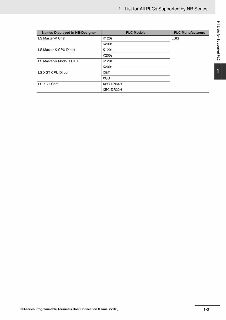
LS Master-K Cnet K120s LSIS
K200s
LS Master-K CPU Direct K120s
K200s
LS Master-K Modbus RTU K120s
K200s
LS XGT CPU Direct XGT
XGB
LS XGT Cnet XBC-DN64H
XBC-DR32H
Names Displayed in NB-Designer PLC Models PLC Manufacturers
1 List for All PLCs Supported by NB Series
1-4 NB-series Programmable Terminals Host Connection Manual (V108)
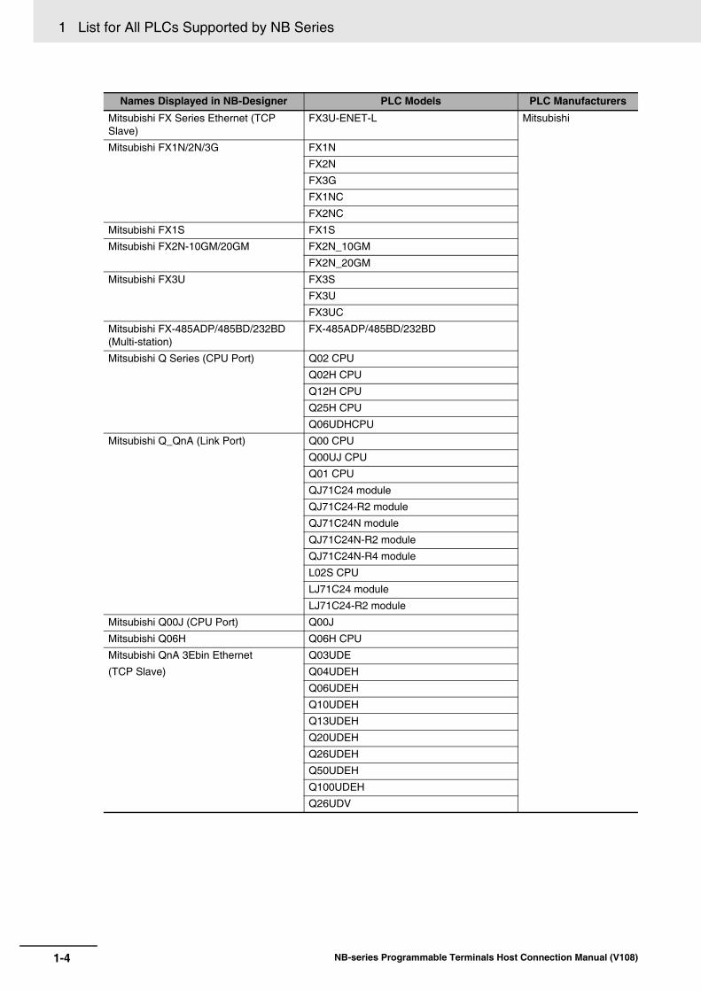
Mitsubishi FX Series Ethernet (TCP Slave)
FX3U-ENET-L Mitsubishi
Mitsubishi FX1N/2N/3G FX1N
FX2N
FX3G
FX1NC
FX2NC
Mitsubishi FX1S FX1S
Mitsubishi FX2N-10GM/20GM FX2N_10GM
FX2N_20GM
Mitsubishi FX3U FX3S
FX3U
FX3UC
Mitsubishi FX-485ADP/485BD/232BD (Multi-station)
FX-485ADP/485BD/232BD
Mitsubishi Q Series (CPU Port) Q02 CPU
Q02H CPU
Q12H CPU
Q25H CPU
Q06UDHCPU
Mitsubishi Q_QnA (Link Port) Q00 CPU
Q00UJ CPU
Q01 CPU
QJ71C24 module
QJ71C24-R2 module
QJ71C24N module
QJ71C24N-R2 module
QJ71C24N-R4 module
L02S CPU
LJ71C24 module
LJ71C24-R2 module
Mitsubishi Q00J (CPU Port) Q00J
Mitsubishi Q06H Q06H CPU
Mitsubishi QnA 3Ebin Ethernet
(TCP Slave)
Q03UDE
Q04UDEH
Q06UDEH
Q10UDEH
Q13UDEH
Q20UDEH
Q26UDEH
Q50UDEH
Q100UDEH
Q26UDV
Names Displayed in NB-Designer PLC Models PLC Manufacturers

1-5
1 List for All PLCs Supported by NB Series
NB-series Programmable Terminals Host Connection Manual (V108)
1-1 Lists for Supported P
LC
1
Mitsubishi QnA 3Ebin Ethernet
(TCP Slave)
L02CPU Mitsubishi
L02CPU-P
L06CPU
L06CPU-P
L26CPU
L26CPU-P
L26CPU-BT
L26CPU-PBT
Mitsubishi QJ71E71 EtherNet Slave QJ71E71-100 module
LJ71E71-100 module
Modbus ASCII Modbus Compatible External Device Modbus
Modbus RTU Modbus Compatible External Device
Modbus RTU Modicon_BE Modbus Compatible External Device
Modbus RTU Extend Modbus Compatible External Device
Modbus RTU Slave Modbus Compatible External Device
Modbus TCP Slave Modbus Compatible External Device
Omron C Series C200HX/HG/HE(-Z) Omron
CQM1H
CPM1/2
Omron CJ/CS Series CS1/CJ1/CJ2
Omron CP1H/L/E CP1H/L/E
Omron NX1 Series Host Link NX1P2-
Omron CJ/CS/NJ Series Ethernet (UDP Slave)
CS1W-ETN21/EIP21
CJ1W-ETN21/EIP21
CJ2H--EIP
CJ2M-CPU3
NJ01
Omron NX1 Series Ethernet (UDP Slave) NX1P2-
Omron CP Series Ethernet (UDP Slave) CP1L-EM
CP1L-EL
CP1W-CIF41
CP1H
CP1L
OMRON G9SP G9SP-N10S
G9SP-N10D
G9SP-N20S
Panasonic FP FP0/FP1/FP2/FP3 Panasonic Industrial Devices SUNXFP2SH
FP10SH/FP10S
FP-M
FP-e
FP-X
Names Displayed in NB-Designer PLC Models PLC Manufacturers
1 List for All PLCs Supported by NB Series
1-6 NB-series Programmable Terminals Host Connection Manual (V108)
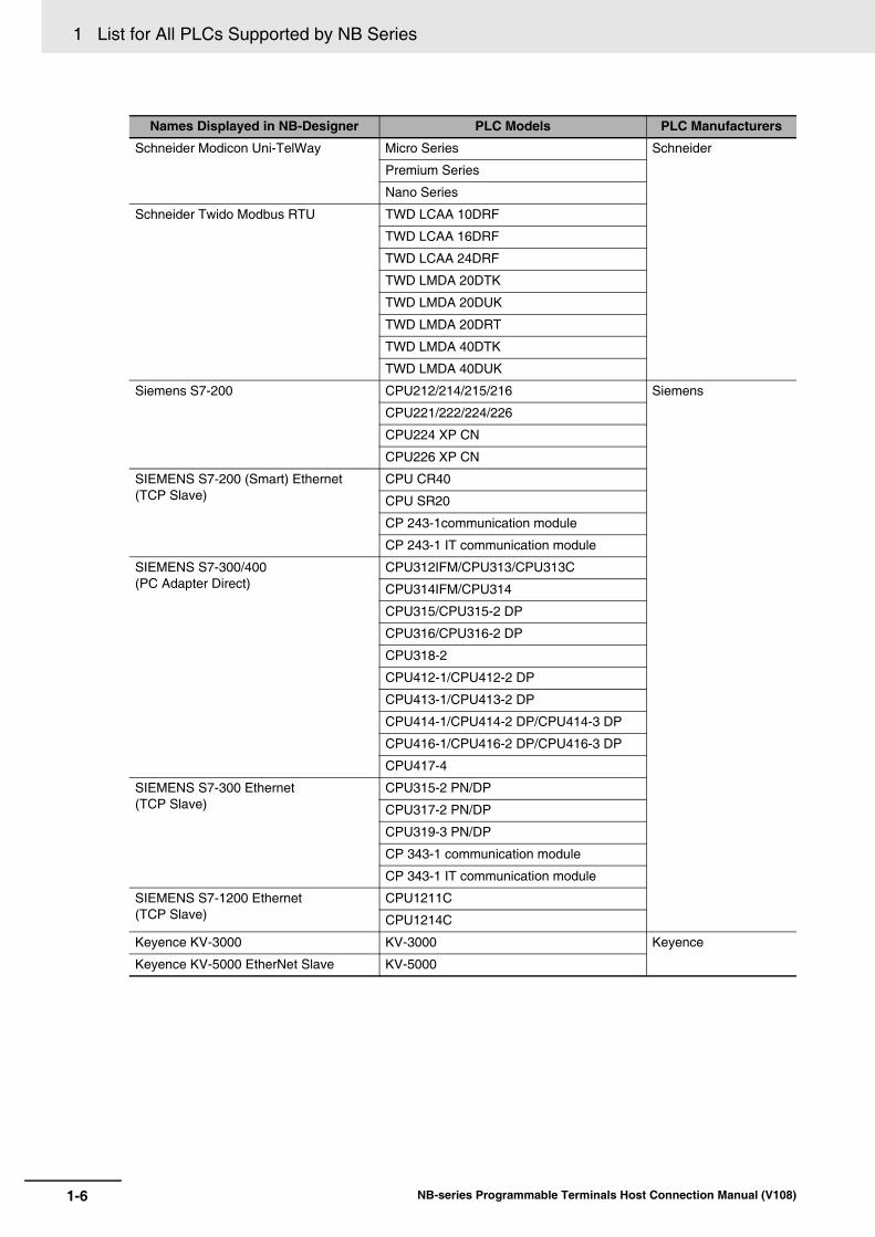
Schneider Modicon Uni-TelWay Micro Series Schneider
Premium Series
Nano Series
Schneider Twido Modbus RTU TWD LCAA 10DRF
TWD LCAA 16DRF
TWD LCAA 24DRF
TWD LMDA 20DTK
TWD LMDA 20DUK
TWD LMDA 20DRT
TWD LMDA 40DTK
TWD LMDA 40DUK
Siemens S7-200 CPU212/214/215/216 Siemens
CPU221/222/224/226
CPU224 XP CN
CPU226 XP CN
SIEMENS S7-200 (Smart) Ethernet (TCP Slave)
CPU CR40
CPU SR20
CP 243-1communication module
CP 243-1 IT communication module
SIEMENS S7-300/400(PC Adapter Direct)
CPU312IFM/CPU313/CPU313C
CPU314IFM/CPU314
CPU315/CPU315-2 DP
CPU316/CPU316-2 DP
CPU318-2
CPU412-1/CPU412-2 DP
CPU413-1/CPU413-2 DP
CPU414-1/CPU414-2 DP/CPU414-3 DP
CPU416-1/CPU416-2 DP/CPU416-3 DP
CPU417-4
SIEMENS S7-300 Ethernet (TCP Slave)
CPU315-2 PN/DP
CPU317-2 PN/DP
CPU319-3 PN/DP
CP 343-1 communication module
CP 343-1 IT communication module
SIEMENS S7-1200 Ethernet (TCP Slave)
CPU1211C
CPU1214C
Keyence KV-3000 KV-3000 Keyence
Keyence KV-5000 EtherNet Slave KV-5000
Names Displayed in NB-Designer PLC Models PLC Manufacturers
1-7
1 List for All PLCs Supported by NB Series
NB-series Programmable Terminals Host Connection Manual (V108)
1-2 Definition and D
escription ofS
erial Port C
OM
1
1-2 Definition and Description of Serial Port COM
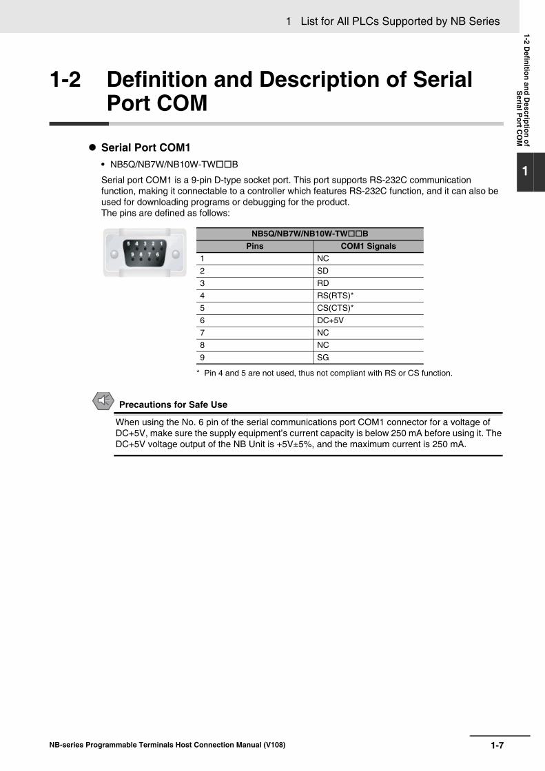
Serial Port COM1• NB5Q/NB7W/NB10W-TWB
Serial port COM1 is a 9-pin D-type socket port. This port supports RS-232C communication function, making it connectable to a controller which features RS-232C function, and it can also be used for downloading programs or debugging for the product. The pins are defined as follows:
Precautions for Safe Use
When using the No. 6 pin of the serial communications port COM1 connector for a voltage of DC+5V, make sure the supply equipment’s current capacity is below 250 mA before using it. The DC+5V voltage output of the NB Unit is +5V±5%, and the maximum current is 250 mA.
* Pin 4 and 5 are not used, thus not compliant with RS or CS function.
NB5Q/NB7W/NB10W-TWBPins COM1 Signals
1 NC2 SD3 RD4 RS(RTS)*5 CS(CTS)*6 DC+5V7 NC8 NC9 SG

1 List for All PLCs Supported by NB Series
1-8 NB-series Programmable Terminals Host Connection Manual (V108)
• NB3Q-TWB
NB3Q-TWB has only 1 serial port COM1, and this port supports communication (non-isolated) based on RS-232C, RS-422 and RS-485, of which only 1 connection mode can be applied at one time. By means of the RS-232C mode (PIN 2~5), it can be connected to a controller based on RS-232C, and can also be used for downloading programs, as well as debugging for the product (connected to a PC). While with the RS-422 or the RS-485 mode (PIN 1, PIN 6~8), only a PLC can be connected.
The pins are defined as follows:
Precaution for Cable Fabrication The COM 2 ports included in this manual and marked by cable manufacturers are intended for the PT of NB5Q/NB7W/NB10W-TWB models, therefore when communication connection is carried out with the COM 1 port of NB3Q-TWB, please refer to the pin definitions in this section prior to connection.
Serial Port COM2• NB5Q/NB7W/NB10W-TWB
Serial port COM2 is a 9-pin D-type socket port. This port supports RS-232C/RS-485/RS-422A communication function.The pins are defined as follows:
* Pin 4 and 5 are not used, thus not compliant with RS or CS function.
Pins Signals I/OFunctions
RS-232C RS-485 RS-422A1 SDB+ I/O - - Sending data(+)2 SD O Sending data - -3 RD I Receiving data - -4 RS(RTS) O Request to send* - -5 CS(CTS) I Clear to send* - -6 RDB+ I/O - RS485B
Send/Receivedata(+)
Receivingdata(+)
7 SDA- I/O - - Sending data(-)8 RDA- I/O - RS485A
Send/Receivedata(-)
Receivingdata(-)
9 SG - Signal ground
Pins Signals I/OFunctions
RS-232C RS-485 RS-422A
1 SDB+ I/O - - Sending data(+)
2 SD O Sending data - -
3 RD I Receiving data - -
4 Terminal R1 - - Terminal resistor
5 Terminal R2 - - Terminal resistor
6 RDB+ I/O - Send/Receive data(+)
Receiving data(+)
7 SDA- I/O - - Sending data(-)
8 RDA- I/O - Send/Receive data(-)
Receiving data(-)
9 SG - Signal ground

2-1NB-series Programmable Terminals Host Connection Manual (V108)
2
This section describes the connection to SIEMENS PLCs.
2-1 Serial Port and Ethernet . . . . . . . . . . . . . . . . . . . . . . . . . . . . . . . . . . . . . . . . 2-22-1-1 Serial Port . . . . . . . . . . . . . . . . . . . . . . . . . . . . . . . . . . . . . . . . . . . . . . . . . . . . 2-22-1-2 Ethernet . . . . . . . . . . . . . . . . . . . . . . . . . . . . . . . . . . . . . . . . . . . . . . . . . . . . . . 2-2
2-2 Communication Parameters and Cable Fabrication . . . . . . . . . . . . . . . . . . 2-32-2-1 Serial Port . . . . . . . . . . . . . . . . . . . . . . . . . . . . . . . . . . . . . . . . . . . . . . . . . . . . 2-32-2-2 Ethernet . . . . . . . . . . . . . . . . . . . . . . . . . . . . . . . . . . . . . . . . . . . . . . . . . . . . . . 2-3
2-3 Communication Parameter Setting . . . . . . . . . . . . . . . . . . . . . . . . . . . . . . . 2-42-3-1 When Using SIEMENS S7-200 Communication Protocol . . . . . . . . . . . . . . . . 2-42-3-2 When Using SIEMENS S7-300/400 (PC Adapter Direct) Communication
Protocol . . . . . . . . . . . . . . . . . . . . . . . . . . . . . . . . . . . . . . . . . . . . . . . . . . . . .2-52-3-3 SIEMENS S7-200 (SMART) Ethernet (TCP Slave) . . . . . . . . . . . . . . . . . . . . . 2-82-3-4 SIEMENS S7-300 Ethernet (TCP Slave) . . . . . . . . . . . . . . . . . . . . . . . . . . . . 2-172-3-5 SIEMENS S7-1200 Ethernet (TCP Slave) . . . . . . . . . . . . . . . . . . . . . . . . . . . 2-23
2-4 Supported Registers . . . . . . . . . . . . . . . . . . . . . . . . . . . . . . . . . . . . . . . . . . 2-272-4-1 SIEMENS S7-200 . . . . . . . . . . . . . . . . . . . . . . . . . . . . . . . . . . . . . . . . . . . . . 2-272-4-2 SIEMENS S7-300/400 (PC Adapter Direct) . . . . . . . . . . . . . . . . . . . . . . . . . . 2-282-4-3 SIEMENS S7-200 (Smart) Ethernet (TCP Slave) . . . . . . . . . . . . . . . . . . . . . 2-282-4-4 SIEMENS S7-300 Ethernet (TCP Slave) . . . . . . . . . . . . . . . . . . . . . . . . . . . . 2-292-4-5 SIEMENS S7-1200 Ethernet (TCP Slave) . . . . . . . . . . . . . . . . . . . . . . . . . . . 2-30
2-5 Cable Fabrication . . . . . . . . . . . . . . . . . . . . . . . . . . . . . . . . . . . . . . . . . . . . . 2-31
Connecting to SIEMENS PLCs

2 Connecting to SIEMENS PLCs
2-2 NB-series Programmable Terminals Host Connection Manual (V108)
2-1 Serial Port and Ethernet
2-1-1 Serial Port
Series CPU Link Module Driver
S7-200
CPU212CPU214CPU215CPU216CPU221CPU222CPU224CPU226CPU224 XP CNCPU226 XP CN
RS485 on the CPU unit SIEMENS S7-200
S7-300
CPU312IFMCPU313CPU313CCPU314CPU314IFMCPU315CPU315-2 DPCPU316CPU316-2 DPCPU318-2
MPI port on the CPU unit SIEMENS S7-300/400 (PC Adapter Direct)
S7-400
CPU412-1CPU412-2 DPCPU413-1CPU413-2 DPCPU414-1CPU414-2 DPCPU414-3 DPCPU416-1CPU416-2 DPCPU416-3 DPCPU417-4
MPI port on the CPU unit
2-1-2 Ethernet
Series CPU Link Module Driver
S7-200
CPU222CPU224CPU226CPU224 XP CNCPU226 XP CN
CP 243-1CP 243-1 IT
SIEMENS S7-200 (Smart) Ethernet (TCP Slave)
S7-200 SMART
CR40SR20
Ethernet interface on CPU
S7-300
CPU315-2DP CP 343-1CP 343-1 IT
SIEMENS S7-300 Ethernet (TCP Slave)
CPU315-2 PN/DPCPU317-2 PN/DPCPU319-3 PN/DP
Ethernet interface on CPU
S7-1200 CPU1211CCPU1214C
Ethernet interface on CPU SIEMENS S7-1200 Ethernet (TCP Slave)

2-3
2 Connecting to SIEMENS PLCs
NB-series Programmable Terminals Host Connection Manual (V108)
2-2 Com
munication P
arameters and C
ableFabrication
2
2-2-1 Serial P
ort
2-2 Communication Parameters and Cable Fabrication
2-2-1 Serial Port
Series CPU Link Module COMM Type Parameter Cable
S7-200
CPU222CPU224CPU226CPU224 XP CNCPU226 XP CN
RS485 on the CPU unit RS232 Refer to Section 2-3
Self-made cable requiredRS485
S7-300
CPU312IFMCPU313CPU313CCPU314CPU314IFMCPU315CPU315-2 DPCPU316CPU316-2 DPCPU318-2
MPI port on the CPU unit RS232
S7-300/400 (PC Adapter Direct) protocol
S7-400
CPU412-1CPU412-2 DPCPU412-3HCPU413-1CPU413-2 DPCPU414-1CPU414-2 DPCPU414-3 DPCPU416-1CPU416-2 DPCPU416-3 DPCPU417-4
MPI port on the CPU unit RS232
S7-300/400 (PC Adapter Direct) protocol
2-2-2 Ethernet
Series CPU Link Module COMM Type Parameter Cable
S7-200
CPU222CPU224CPU226CPU224 XP CNCPU226 XP CN
CP 243-1CP 243-1 IT
- Refer to Section 2-3
Network Cable
S7-200 SMART
CR40SR20
Ethernet Port of CPU Unit -
S7-300
CPU315-2DP CP 343-1CP 343-1 IT
-
CPU315-2 PN/DPCPU317-2 PN/DPCPU319-3 PN/DP
Ethernet Port of CPU Unit -
S7-1200 CPU1211CCPU1214C
Ethernet Port of CPU Unit -
2 Connecting to SIEMENS PLCs
2-4 NB-series Programmable Terminals Host Connection Manual (V108)
2-3 Communication Parameter Setting
PT default communication parameters: 9600bps (Baud Rate), 8 (Data Bit), 1 (Stop Bit), even(Parity Check) and 2 (PLC Station No.)
Note The maximum communication baud rate is 187.5K that is not supported by the direct online. The PLC No. should match with the PLC No. in PT. Because the PLC address of S7-200 ranges from 1 to126, so the PLC No. in PT should also range from 1 to 126.
RS485 Communication
RS232 Communication
2-3-1 When Using SIEMENS S7-200 Communication Protocol
PT Settings

2-5
2 Connecting to SIEMENS PLCs
NB-series Programmable Terminals Host Connection Manual (V108)
2-3 Com
munication P
arameter S
etting
2
2-3-2 When U
sing SIE
ME
NS
S7-300/400 (P
C A
dapter Direct) C
omm
unication Protocol
PT default communication parameters: 19200bps(Baud Rate), 8(Data Bit), 2(Stop Bit), odd (Parity Check) and 2 (PLC Station No.) (Multiple Station No. is not supported.)
RS232 Communication
PLC Settings
2-3-2 When Using SIEMENS S7-300/400 (PC Adapter Direct) Communication Protocol
PT Settings

2 Connecting to SIEMENS PLCs
2-6 NB-series Programmable Terminals Host Connection Manual (V108)
Note 1 The PLC Station No. is not needed if the PC adapter is used, which realize one for one communication.
2 When MPI-Adapter SSW7, RS232 (Order No.700-751-1VK21) manufactured by Helmholz is used, set thecommunication speed as follows. Also the firmware of the MPI-Adapter should be V3.4b7 or later.
• PLC communication speed: 19.2/187.5 kbps
• PT communication speed: 9600/14400/19200/38400/56000/57600/115200 bps
3 DB blocks should be established in PLC program configuration, otherwise the relevant registers (DB.DBX,DB.DBW, DB.DBD) can not be written. The even parity should be used on the initial addresses ofDBm.DBW and DBm.DBD.
Note For information of the product manufactured by Helmholz, please access to website as follows.Systeme Helmholz GmbH http://www.helmholz.de/If the firmware version of the purchased MPI-Adapter is old, please download SHTools from website asabove to update the firmware.
1 When MPI-Adapter manufactured by Helmholz is used, set the communication speed of PLC to 19.2 Kbps or 187.5 Kbps.
2 The MPI address must be 2.
PLC Settings

2-7
2 Connecting to SIEMENS PLCs
NB-series Programmable Terminals Host Connection Manual (V108)
2-3 Com
munication P
arameter S
etting
2
2-3-2 When U
sing SIE
ME
NS
S7-300/400 (P
C A
dapter Direct) C
omm
unication Protocol
3 Download the set parameters to PLC after the setting is completed. Then open [SIMATIC Manager] menu-[Option]-[PG/PC Interface Setting], select PC Adapter (MPI) and modify the transmission rate of MPI port to be 187.5K, as shown below:

2 Connecting to SIEMENS PLCs
2-8 NB-series Programmable Terminals Host Connection Manual (V108)
2-3-3 SIEMENS S7-200 (SMART) Ethernet (TCP Slave)
PT Settings

2-9
2 Connecting to SIEMENS PLCs
NB-series Programmable Terminals Host Connection Manual (V108)
2-3 Com
munication P
arameter S
etting
2
2-3-3 SIE
ME
NS
S7-200 (S
MA
RT
) Ethernet (T
CP
Slave)
Note When you use S7-200 SMART, observe the following setting. Set the [PLC property] - [Protocol Time Out 2] to "20".
Using Ethernet Port of CPU UnitWhen you use the Unit that uses built-in Ethernet Port, set the Unit with STEP7-MICRO/WIN Smart.
1 Double-click the [Communications].
PLC Settings

2 Connecting to SIEMENS PLCs
2-10 NB-series Programmable Terminals Host Connection Manual (V108)
2 Connect the PLC to be connected on the Ethernet Network that is connectable with PC and click the [Find CPUs].
3 Select the found CPU and click the [Edit] button.

2-11
2 Connecting to SIEMENS PLCs
NB-series Programmable Terminals Host Connection Manual (V108)
2-3 Com
munication P
arameter S
etting
2
2-3-3 SIE
ME
NS
S7-200 (S
MA
RT
) Ethernet (T
CP
Slave)
4 Set IP address and others and click the [Set] button.
Using communication moduleWhen you use communication module, make settings with STEP7 Micro/Win.
1 Select the [Tools] - [Ethernet Wizard...] from Menu.

2 Connecting to SIEMENS PLCs
2-12 NB-series Programmable Terminals Host Connection Manual (V108)
2 Click the [Next>] button.
3 Set the Module Position to "0" and click the [Next>] button.
Precautions for Correct UsePrecautions for Correct Use
In order to communicate with the NB, the Module Position must be "0". If yours not the case,change the CPU configurations and set the Module Position to "0".

2-13
2 Connecting to SIEMENS PLCs
NB-series Programmable Terminals Host Connection Manual (V108)
2-3 Com
munication P
arameter S
etting
2
2-3-3 SIE
ME
NS
S7-200 (S
MA
RT
) Ethernet (T
CP
Slave)
4 Make settings of IP address and others and select the [Auto Detect Communications] for the [Module Connection Type].When completing the settings, click the [Next>] button.
5 Make settings as below and click the [Next>] button.

2 Connecting to SIEMENS PLCs
2-14 NB-series Programmable Terminals Host Connection Manual (V108)
6 Make settings as below and click the [OK] button.
7 Make settings as below and click the [Next>] button.

2-15
2 Connecting to SIEMENS PLCs
NB-series Programmable Terminals Host Connection Manual (V108)
2-3 Com
munication P
arameter S
etting
2
2-3-3 SIE
ME
NS
S7-200 (S
MA
RT
) Ethernet (T
CP
Slave)
8 Click the [Suggest Address] button and then the [Next>] button.
9 Click the [Finish] button.
10Click the [Yes] button.

2 Connecting to SIEMENS PLCs
2-16 NB-series Programmable Terminals Host Connection Manual (V108)
11Correct your program to call the subroutine ETH0_CTRL for each cycle.

2-17
2 Connecting to SIEMENS PLCs
NB-series Programmable Terminals Host Connection Manual (V108)
2-3 Com
munication P
arameter S
etting
2
2-3-4 SIE
ME
NS
S7-300 E
thernet (TC
P S
lave)
Using Ethernet Port of CPU UnitMake settings with SIMATIC STEP 7 (TIA Portal).
2-3-4 SIEMENS S7-300 Ethernet (TCP Slave)
PT Settings
PLC Settings

2 Connecting to SIEMENS PLCs
2-18 NB-series Programmable Terminals Host Connection Manual (V108)
1 Double-click the [General] tab - [PROFINET interface [X3]] - [Ethernet addresses] and set IP address and others.
2 Transfer the set descriptions to the PLC. If you transfer the descriptions for the first time, select the [Extended download to device] and check in the [Show All compatible devices] check box.

2-19
2 Connecting to SIEMENS PLCs
NB-series Programmable Terminals Host Connection Manual (V108)
2-3 Com
munication P
arameter S
etting
2
2-3-4 SIE
ME
NS
S7-300 E
thernet (TC
P S
lave)
3 Create a Data block.Double-click the [Project tree] - [Add new block].
4 Click the Data Block.Example: If you create a new Data block DB10, make settings as below.

2 Connecting to SIEMENS PLCs
2-20 NB-series Programmable Terminals Host Connection Manual (V108)
Additional Information
• If you use the Data block, the data type of the NB and the PLC should be the same. Forinstance, if the Data type of the PLC is REAL, the storing data type of the numeric input com-ponent should be Float.
• When you define the Data block, secure the larger area than the one used for the NB. Forinstance, in order to use DB5.DBW32 in the NB, you need to secure DB5.DBW34 or later forthe PLC.
• If you use the data block, do not check in the check box, [Properties] - [Attributes] - [Only storein load memory].
Using communication moduleMake settings with SIMATIC STEP 7 (TIA Portal).
1 Open the [Device overview] and click the [PLC].
2 Click the [General] tab - [MPI address]. Set the [Parameters] - [Address] to "2".

2-21
2 Connecting to SIEMENS PLCs
NB-series Programmable Terminals Host Connection Manual (V108)
2-3 Com
munication P
arameter S
etting
2
2-3-4 SIE
ME
NS
S7-300 E
thernet (TC
P S
lave)
3 Select the Model from [CP 343-1] - [Hardware catalog] and double-click on the Model.
4 Click the [General] tab - [MPI address]. Set the [Connection to backplane bus] - [Address] to "3".
2 Connecting to SIEMENS PLCs
2-22 NB-series Programmable Terminals Host Connection Manual (V108)
5 Click the [General] tab - [Ethernet addresses]. Make settings IP address and others.
6 Download the settings to the PLC.
2-23
2 Connecting to SIEMENS PLCs
NB-series Programmable Terminals Host Connection Manual (V108)
2-3 Com
munication P
arameter S
etting
2
2-3-5 SIE
ME
NS
S7-1200 E
thernet (TC
P S
lave)
2-3-5 SIEMENS S7-1200 Ethernet (TCP Slave)
PT Settings
2 Connecting to SIEMENS PLCs
2-24 NB-series Programmable Terminals Host Connection Manual (V108)
Make settings of the PLC using SIMATIC STEP 7 (TIA Portal).
1 Double-click the [General] tab - [PROFINET interface] - [Ethernet addresses] and set IP address and others.
2 Transfer the set descriptions to the PLC. If you transfer the descriptions for the first time, select the [Extended download to device] and check the [Show All compatible devices] check box.
PLC Settings
2-25
2 Connecting to SIEMENS PLCs
NB-series Programmable Terminals Host Connection Manual (V108)
2-3 Com
munication P
arameter S
etting
2
2-3-5 SIE
ME
NS
S7-1200 E
thernet (TC
P S
lave)
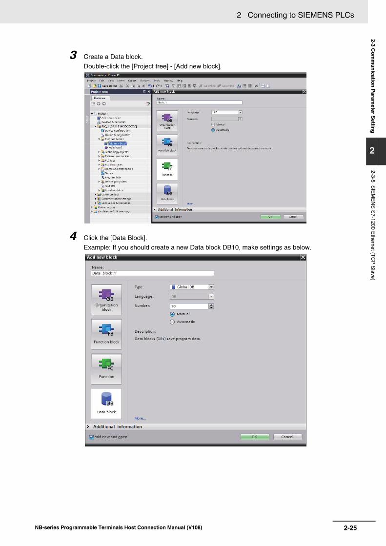
3 Create a Data block.Double-click the [Project tree] - [Add new block].
4 Click the [Data Block].Example: If you should create a new Data block DB10, make settings as below.

2 Connecting to SIEMENS PLCs
2-26 NB-series Programmable Terminals Host Connection Manual (V108)
Precautions for Correct UsePrecautions for Correct Use
• If you use the Data block, the data type of the NB and the PLC should be the same. Forinstance, if the Data type of the PLC is REAL, the storing data type of the numeric input com-ponent should be Float.
• When you define the Data block, secure the larger area than the one used for the NB. Forinstance, in order to use DB5.DBW32 in the NB, you need to secure DB5.DBW34 or later forthe PLC.
• If you use the data block, do not check in the check box, [Properties] - [Attributes] - [Only storein load memory].

2-27
2 Connecting to SIEMENS PLCs
NB-series Programmable Terminals Host Connection Manual (V108)
2-4 Supported R
egisters
2
2-4-1 SIE
ME
NS
S7-200
2-4 Supported Registers
Note The initial addresses of VW and VD must be even. Address format description: D: decimal, O: octonary, H: hexadecimal.
2-4-1 SIEMENS S7-200
Device Bit Address Word Address Format Notes
SCR Nodes S.B 0.0~31.7 ------ DD.O
Special Memory Bit SM.B 0.0~549.7 ------ DDD.O
Counter Bit Cnt 0~255 ------ DDD.O
Counter Bit Tim 0~255 ------ DDD.O
Variable Memory Nodes V.B 0.0~10238.7 ------ DDDDD.O
Internal Memory Bit M.B 0.0~31.7 ------ DD.O
Discrete Output and Map Register Nodes Q.B 0.0~15.7 ------ DD.O
Discrete Input and Map Register Nodes I.B 0.0~15.7 ------ DD.O
Analog Output ------ AQW 0~62 DD
Analog Input: ------ AIW 0~62 DD
SCR (32-bit) ------ SD 0~28 DD
SCR ------ SW 0~30 DD
Special Memory Registers (32-bit) ------ SMD 0~546 DDD
Special Memory Registers ------ SMW 0~548 DDD
Internal Memory Bit (32-bit) ------ MD 0~28 DD
Internal Memory ------ MW 0~30 DD
Discrete Output and Map Registers (32-bit) ------ QD 0~12 DD
Discrete Output and Map Registers ------ QW 0~14 DD
Discrete Input and Map Registers (32-bit) ------ ID 0~12 DD
Discrete Input and Map Registers ------ IW 0~14 DD
Counter PV ------ Cnt 0~255 DDD
Timer PV ------ Tim 0~255 DDD
Variable Memory (32-bit) ------ VD 0~10236 DDDDD
Variable Memory ------ VW 0~10238 DDDDD

2 Connecting to SIEMENS PLCs
2-28 NB-series Programmable Terminals Host Connection Manual (V108)
Note The initial addresses of DBm.DBW and DBm.DBD must be even.Address format description: D: decimal, O: octonary, H: hexadecimal.
Note When you access word access and double word access memories, always specify even address.
2-4-2 SIEMENS S7-300/400 (PC Adapter Direct)
Device Bit Address Word Address Format Notes
External Input Nodes I 0.0~511.7 ------ DDDD.O
External Output Nodes Q 0.0~511.7 ------ DDDD.O
Internal Auxiliary Nodes M 0.0~4095.7 ------ DDDD.O
Data Register Nodes DBm.DBX 0~65535.7 ------ DDDDD.O m: 10 to 29
Data Registers ------ DBm.DBW 0~65534 DDDDD m: 10 to 60
Data Registers (32-bit) ------ DBm.DBD 0~65532 DDDDD m: 10 to 60
Internal Registers ------ MW 0~2046 DDDD
Internal Registers (32-bit) ------ MD 0~2044 DDDD
External Output Registers ------ QW 0~126 DDD
External Output Registers (32-bit) ------ QD 0~124 DDD
External Input Registers ------ IW 0~126 DDD
External Input Registers (32-bit) ------ ID 0~124 DDD
2-4-3 SIEMENS S7-200 (Smart) Ethernet (TCP Slave)
Device Bit Address Word Address Format Notes
Discrete Input and Map Register Nodes I.B 0.0~31.7 ------ DD.O
Internal Memory Bit M.B 0.0~31.7 ------ DD.O
Discrete Output and Map Register Nodes Q.B 0.0~31.7 ------ DD.O
SCR Nodes S.B 0.0~31.7 ------ DD.O
Special Memory Bit SM.B 0.0~1535.7 ------ DDDD.O
Variable Memory Nodes V.B 0.0~8191.7 ------ DDDD.O
Analog Inputs ------ AIW 0~110 DDD
Analog Outputs ------ AQW 0~110 DDD
Discrete Input and Map Registers (32-bit) ------ ID 0~28 DD
Discrete Input and Map Registers ------ IW 0~30 DD
Internal Memory (32-bit) ------ MD 0~28 DD
Internal Memory ------ MW 0~30 DD
Discrete Output and Map Registers (32-bit) ------ QD 0~28 DD
Discrete Output and Map Registers ------ QW 0~30 DD
SCR (32-bit) ------ SD 0~28 DD
Special Memory Registers (32-bit) ------ SMD 0~1532 DDDD
Special Memory Registers ------ SMW 0~1534 DDDD
SCR ------ SW 0~30 DD
Variable Memory (32-bit) ------ VD 0~8188 DDDD
Variable Memory ------ VW 0~8190 DDDD

2-29
2 Connecting to SIEMENS PLCs
NB-series Programmable Terminals Host Connection Manual (V108)
2-4 Supported R
egisters
2
2-4-4 SIE
ME
NS
S7-300 E
thernet (TC
P S
lave)
Note 1 DBn_DBX, DBn_DBW, and DBn_DBD represent custom blocks. The top three digits of the Data block address indi-cate block number. The other five digits after the block number indicate address. If the address part is less than fivedigits, fill in '0's. For instance, if you access to DB20.DBX23.4, set DBn_DBX to 2000023.4.
2 When you access word access and double word access memories, always specify even address.
3 MB, IB, and QB do not support the signed integer number as data format.
4 If you define the Data block, secure the larger area than that used in the NB. For instance, if you use DB5.DBW32 inthe NB, you should secure DB5.DBW34 or later in the PLC.
5 When you access data block of double word, you cannot access the maximum address.
2-4-4 SIEMENS S7-300 Ethernet (TCP Slave)
Device Bit Address Word Address Format Note
Data Register Nodes DBm_DBX 0.0~65535.7
------ DDDDD.O m:1 to 10
Data Register Nodes DBn_DBX 100000.0~25565535.7
------ DDDDDDDD.O
n:1 to 255
External Input Nodes I 0.0~2047.7 ------ DDDD.O
Internal Auxiliary Nodes M 0.0~8191.7 ------ DDDD.O
External Output Nodes Q 0.0~2047.7 ------ DDDD.O
Data Registers (8-bit) ------ DBm_DBB 0~65535 DDDDD m:1 to 10
Data Registers Nodes ------ DBm_DBB 0~65535 DDDDD m:1 to 10
Data Registers (32-bit) ------ DBm_DBD 0~65532 DDDDD m:1 to 10
Data Registers ------ DBm_DBW 0~65534
DDDDD m:1 to 10
Data Registers ------ DBn_DBB 100000~25565535
DDDDDDDD n:1 to 255
Data Registers (32-bit) ------ DBn_DBD 100000~25565532
DDDDDDDD n:1 to 255
Data Registers ------ DBn_DBW 100000~25565534
DDDDDDDD n:1 to 255
External Output Nodes ------ IB 0~2047 DDDD
External Input Registers (32-bit) ------ ID 0~2044 DDDD
External Input Registers ------ IW 0~2046 DDDD
External Input Nodes ------ MB 0~8191 DDDD
Internal Registers (32-bit) ------ MD 0~8188 DDDD
Internal Registers ------ MW 0~8190 DDDD
Internal Assistant Nodes ------ QB 0~2047 DDDD
External Output Registers (32-bit) ------ QD 0~2044 DDDD
External Output Registers ------ QW 0~2046 DDDD
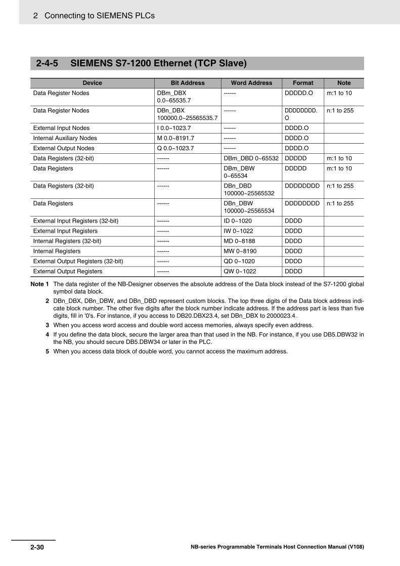
2 Connecting to SIEMENS PLCs
2-30 NB-series Programmable Terminals Host Connection Manual (V108)
Note 1 The data register of the NB-Designer observes the absolute address of the Data block instead of the S7-1200 globalsymbol data block.
2 DBn_DBX, DBn_DBW, and DBn_DBD represent custom blocks. The top three digits of the Data block address indi-cate block number. The other five digits after the block number indicate address. If the address part is less than fivedigits, fill in '0's. For instance, if you access to DB20.DBX23.4, set DBn_DBX to 2000023.4.
3 When you access word access and double word access memories, always specify even address.
4 If you define the data block, secure the larger area than that used in the NB. For instance, if you use DB5.DBW32 inthe NB, you should secure DB5.DBW34 or later in the PLC.
5 When you access data block of double word, you cannot access the maximum address.
2-4-5 SIEMENS S7-1200 Ethernet (TCP Slave)
Device Bit Address Word Address Format Note
Data Register Nodes DBm_DBX 0.0~65535.7
------ DDDDD.O m:1 to 10
Data Register Nodes DBn_DBX 100000.0~25565535.7
------ DDDDDDDD.O
n:1 to 255
External Input Nodes I 0.0~1023.7 ------ DDDD.O
Internal Auxiliary Nodes M 0.0~8191.7 ------ DDDD.O
External Output Nodes Q 0.0~1023.7 ------ DDDD.O
Data Registers (32-bit) ------ DBm_DBD 0~65532 DDDDD m:1 to 10
Data Registers ------ DBm_DBW 0~65534
DDDDD m:1 to 10
Data Registers (32-bit) ------ DBn_DBD 100000~25565532
DDDDDDDD n:1 to 255
Data Registers ------ DBn_DBW 100000~25565534
DDDDDDDD n:1 to 255
External Input Registers (32-bit) ------ ID 0~1020 DDDD
External Input Registers ------ IW 0~1022 DDDD
Internal Registers (32-bit) ------ MD 0~8188 DDDD
Internal Registers ------ MW 0~8190 DDDD
External Output Registers (32-bit) ------ QD 0~1020 DDDD
External Output Registers ------ QW 0~1022 DDDD

2-31
2 Connecting to SIEMENS PLCs
NB-series Programmable Terminals Host Connection Manual (V108)
2-5 Cable Fabrication
2
2-5 Cable Fabrication
RS232 Communication CableUse RS-232/PPI multi-host cable and self-made RS232 cable manufactured by SIEMENS to communicate with PT.
• Self-made RS-232 Cable
RS485 Communication Cable
RS232 Communication CableUse MPI-Adapter SSW7, RS232 (Order No.700-751-1VK21) manufactured by Helmholz and RS232 cable to communicate to PT.
When Using SIEMENS S7-200 Communication Protocol
When Using SIEMENS S7-300/400 (PC Adapter Direct) Communication Protocol
PT (COM1/COM2)Pin No.
239
SignalSDRDSG
D-Sub 9Pin
(Female)
RS-232/PPI cable connectorPin No.
235
SignalRXDTXDGND
D-Sub 9Pin
(Female)
PT (COM2)Pin No.
689
SignalRDB+RDA-SG
D-Sub 9Pin
(Female)
PLCPin No.
385
SignalD+D-
GND
D-Sub 9Pin
(Female)
45
Terminal R1 Terminal R2
PT (COM1/COM2)
Pin No.239
SignalSDRDSG
D-Sub9Pin
(Female) D-Sub9Pin
(Male)
MPI-Adapter RS-232 cableconnector
Pin No.2345678
SignalRXDTXDDTRGNDDSRRTSCTS

2 Connecting to SIEMENS PLCs
2-32 NB-series Programmable Terminals Host Connection Manual (V108)

3-1NB-series Programmable Terminals Host Connection Manual (V108)
3This section describes the connection to Mitsubishi PLCs.
3-1 Serial Port and Ethernet . . . . . . . . . . . . . . . . . . . . . . . . . . . . . . . . . . . . . . . . 3-23-1-1 Serial Port . . . . . . . . . . . . . . . . . . . . . . . . . . . . . . . . . . . . . . . . . . . . . . . . . . . . 3-23-1-2 Ethernet . . . . . . . . . . . . . . . . . . . . . . . . . . . . . . . . . . . . . . . . . . . . . . . . . . . . . . 3-3
3-2 Communication Setting and Cable Connection . . . . . . . . . . . . . . . . . . . . . 3-43-2-1 Serial Port . . . . . . . . . . . . . . . . . . . . . . . . . . . . . . . . . . . . . . . . . . . . . . . . . . . . 3-43-2-2 Ethernet . . . . . . . . . . . . . . . . . . . . . . . . . . . . . . . . . . . . . . . . . . . . . . . . . . . . . . 3-5
3-3 Communication Setting . . . . . . . . . . . . . . . . . . . . . . . . . . . . . . . . . . . . . . . . . 3-63-3-1 When Using Mitsubishi FX1S, Mitsubishi FX1N/2N/3G and Mitsubishi FX3U
Communication Protocols . . . . . . . . . . . . . . . . . . . . . . . . . . . . . . . . . . . . . . . . 3-63-3-2 When Using Mitsubishi FX-485ADP/485BD/232BD (Multi-station)
Communication Protocols . . . . . . . . . . . . . . . . . . . . . . . . . . . . . . . . . . . . . . . . 3-8
3-3-3 When Using FX2N-10GM/20GM Communication Protocol . . . . . . . . . . . . . . 3-113-3-4 When Using Mitsubishi Q00J (CPU Port) Communication Protocol . . . . . . . 3-123-3-5 When Using Mitsubishi Q series (CPU Port) Communication Protocol . . . . . 3-123-3-6 When Using Mitsubishi Q06H Communication Protocol . . . . . . . . . . . . . . . . 3-13
3-3-7 When Using Mitsubishi Q_QnA (Link Port) Communication Protocol . . . . . . 3-143-3-8 When Using Mitsubishi FX Series Ethernet(TCP Slave) Communication
Protocol . . . . . . . . . . . . . . . . . . . . . . . . . . . . . . . . . . . . . . . . . . . . . . . . . . . . . 3-193-3-9 When Using Mitsubishi QnA 3EBin Ethernet (TCP Slave) Communication
Protocol . . . . . . . . . . . . . . . . . . . . . . . . . . . . . . . . . . . . . . . . . . . . . . . . . . . . . 3-223-3-10 When Using Mitsubishi QJ71E71 EtherNet Slave Communication
Protocol . . . . . . . . . . . . . . . . . . . . . . . . . . . . . . . . . . . . . . . . . . . . . . . . . . . . . 3-25
3-4 Supported Registers . . . . . . . . . . . . . . . . . . . . . . . . . . . . . . . . . . . . . . . . . . 3-28
3-5 Cable Fabrication . . . . . . . . . . . . . . . . . . . . . . . . . . . . . . . . . . . . . . . . . . . . . 3-34
Connecting to Mitsubishi PLCs

3 Connecting to Mitsubishi PLCs
3-2 NB-series Programmable Terminals Host Connection Manual (V108)
3-1 Serial Port and Ethernet
3-1-1 Serial Port
Series CPU Link Module(The products in ( ) are also needed) Driver
FXCPU FX1S RS422 on the CPU unit Mitsubishi FX1S *2
FX2NC-485-ADP (FX1N-CNV-BD) FX0N-485-ADP (FX1N-CNV-BD) FX1N--BD
Mitsubishi FX1S *2 Mitsubishi FX-485ADP/485BD/232BD (Multi-station) *1
FX1N RS422 on the CPU unit Mitsubishi FX1N/2N/3G *2
FX2NC-485-ADP (FX1N-CNV-BD) FX0N-485-ADP (FX1N-CNV-BD) FX1N--BD
Mitsubishi FX1N/2N/3G *2 Mitsubishi FX-485ADP/485BD/232BD (Multi-station) *1
FX2N RS422 on the CPU unit Mitsubishi FX1N/2N/3G *2
FX2NC-485-ADP (FX1N-CNV-BD) FX0N-485-ADP (FX1N-CNV-BD) FX2N--BD
Mitsubishi FX1S *2 Mitsubishi FX-485ADP/485BD/232BD (Multi-station) *1
FX1NC RS422 on the CPU unit Mitsubishi FX1N/2N/3G *2
FX2NC-485-ADP (FX1N-CNV-BD) FX0N-485-ADP (FX1N-CNV-BD)
Mitsubishi FX1N/2N/3G *2 Mitsubishi FX-485ADP/485BD/232BD (Multi-station)
FX2NC RS422 on the CPU unit Mitsubishi FX1N/2N/3G *2
FX2NC-485-ADP (FX1N-CNV-BD) FX0N-485-ADP (FX1N-CNV-BD)
Mitsubishi FX1N/2N/3G *2 Mitsubishi FX-485ADP/485BD/232BD (Multi-station)
FX2N-10GM FX2N-20GM
RS422 on the CPU unit Mitsubishi FX2N_10GM/20GM
FX3UFX3UCFX3S
RS422 on the CPU unit Mitsubishi FX3U *2
FX3U--BDFX3U-485-ADP (FX3U-CNV_BD)
Mitsubishi FX3U *2 Mitsubishi FX-485ADP/485BD/232BD (Multi-station) *1
FX3GFX3GC
RS422 on the CPU unit Mitsubishi FX1N/2N/3G *2
FX3G--BDFX3U-485-ADP (FX3G-CNV-ADP)
Mitsubishi FX-485ADP/485BD/232BD (Multi-station) *1
MELSEC Q Q00JCPU RS232 on the CPU unit Mitsubishi Q00J (CPU Port)
QJ71C24QJ71C24-R2QJ71C24NQJ71C24N-R2QJ71C24N-R4
Mitsubishi Q_QnA (Link Port)
Q00CPUQ01CPU
QJ71C24QJ71C24-R2QJ71C24NQJ71C24N-R2QJ71C24N-R4
Mitsubishi Q_QnA (Link Port)
Q02CPUQ02HCPUQ12HCPUQ25HCPU
RS232 on the CPU unit Mitsubishi Q Series (CPU Port)
QJ71C24QJ71C24-R2QJ71C24NQJ71C24N-R2QJ71C24N-R4
Mitsubishi Q_QnA (Link Port)

3-3
3 Connecting to Mitsubishi PLCs
NB-series Programmable Terminals Host Connection Manual (V108)
3-1 Serial P
ort and Ethernet
3
3-1-2 Ethernet *1 This protocol supports Multiple Station No..
*2 This protocol does not support Multiple Station No..
MELSEC Q Q06HCPU RS232 on the CPU unit Mitsubishi Q06H
QJ71C24QJ71C24-R2QJ71C24NQJ71C24N-R2QJ71C24N-R4
Mitsubishi Q_QnA (Link Port)
Q00UJCPU RS232 on the CPU unit Mitsubishi Q_QnA (Link Port)
Q06UDHCPU RS232 on the CPU unit Mitsubishi Q Series (CPU Port)
MELSEC L L02CPUL02CPU-PL02SCPU-PL06CPUL06CPU-PL26CPUL26CPU-PL26CPU-BTL26CPU-PBT
LJ71C24LJ71C24-R2
Mitsubishi Q_QnA (Link Port)
L02SCPU RS232C port on CPU UnitLJ71C24LJ71C24-R2
Mitsubishi Q_QnA (Link Port)
3-1-2 Ethernet
Series CPU Link Module Driver
FXCPU FX3U FX3U-ENET-L Mitsubishi FX Series Ethernet (TCP Slave)
MELSEC Q Q03UDEQ04UDEHQ06UDEHQ10UDEHQ13UDEHQ20UDEHQ26UDEHQ50UDEHQ100UDEHQ26UDV
Ethernet Port on CPU Unit Mitsubishi QnA 3EBin Ethernet (TCP Slave)
Q00CPUQ00JCPUQ01CPUQ02CPUQ02HCPUQ06HCPUQ12HCPUQ25HCPU
QJ71E71-100 Mitsubishi QJ71E71 EtherNet Slave
MELSEC L L02CPUL02CPU-PL06CPUL06CPU-PL26CPUL26CPU-PL26CPU-BTL26CPU-PBT
Ethernet Port on CPU Unit Mitsubishi QnA 3EBin Ethernet (TCP Slave)
LJ71E71-100 Mitsubishi QJ71E71 EtherNet Slave
L02SCPUL02SCPU-P
LJ71E71-100 Mitsubishi QJ71E71 EtherNet Slave
Series CPU Link Module(The products in ( ) are also needed) Driver

3 Connecting to Mitsubishi PLCs
3-4 NB-series Programmable Terminals Host Connection Manual (V108)
3-2 Communication Setting and Cable Connection
3-2-1 Serial Port
Series CPU Link Module COMM Type Parameter Cable
FXCPU FX1S FX1N FX2N
RS422 on the CPU unit RS422 Refer to Section 3-3 Self-made cable requiredRS232 Module RS232
RS485 Module RS422
FX1NC FX2NC
RS422 on the CPU unit RS422
RS485 Module RS422
FX2N-10GM FX2N-20GM
RS422 on the CPU unit RS422
FX3GFX3GC
RS422 on the CPU unit RS422
RS232 Module RS232
RS485 Module RS422
FX3UC FX3UFX3S
RS422 on the CPU unit RS422
RS232 Module RS422
RS485 Module RS422
MELSEC Q Q00JCPUQ02CPUQ02HCPUQ12HCPUQ25HCPUQ06HCPUQ00UJ CPUQ06UDHCPU
RS232 on the CPU unit RS232
Q00JCPUQ00CPUQ01CPUQ02CPUQ02HCPUQ12HCPUQ25HCPUQ06HCPU
QJ71C24QJ71C24-R2QJ71C24NQJ71C24N-R2
RS232
QJ71C24QJ71C24NQJ71C24N-R4
RS422
MELSEC L L02SCPU RS232 on the CPU unit RS232
L02CPUL02CPU-PL02SCPUL02SCPU-PL06CPUL06CPU-PL26CPUL26CPU-PL26CPU-BTL26CPU-PBT
LJ71C24LJ71C24-R2
RS232
LJ71C24 RS422

3-5
3 Connecting to Mitsubishi PLCs
NB-series Programmable Terminals Host Connection Manual (V108)
3-2 Com
munication S
etting and Cable C
onnection
3
3-2-2 Ethernet
3-2-2 Ethernet
Series CPU Link Module COMM Type Parameter Cable
FXCPU FX3U FX3U-ENET-L - Refer to Section 3-3 Network Cable
MELSEC Q Q00JCPUQ00CPUQ01CPUQ02CPUQ02HCPUQ12HCPUQ25HCPUQ26UDVCPU
QJ71E71-100 -
Q03UDECPUQ04UDEHCPUQ06UDEHCPUQ10UDEHCPUQ13UDEHCPUQ20UDEHCPUQ26UDEHCPUQ100UDEHCPU
Ethernet Port on CPU Unit -
MELSEC L L02SCPUL02SCPU-P
LJ71E71-100 -
L02CPUL02CPU-PL06CPUL06CPU-PL26CPUL26CPU-PL26CPU-BTL26CPU-PBT
Ethernet Port on CPU UnitLJ71E71-100
-

3 Connecting to Mitsubishi PLCs
3-6 NB-series Programmable Terminals Host Connection Manual (V108)
3-3 Communication Setting
PT default communication parameters: 9600bps (Baud Rate), 7 (Data Bit), even (Parity Check), 1 (Stop Bit) and 0 (PLC Station No.)
The PLC Communication Time Out, Max interval of word (bit) block pack, Max size of word(bit) block package on the right of the dialog box vary with PLC protocols. Generally the defaults are selected.
Note This protocol can be used when communicating with the PLC through the programming port of the CPU andthe Functions Extension board. This Protocol does not support Multiple Station No. of the Function Exten-sion board. The supporting Baud Rates are as follows. If other Baud Rates than these are selected, the com-munication is unavailable.9600bps, 115200bps: FX3G, FX3GC, FX3S, FX3U, FX3UC9600bps fixed: other CPUs than above
RS422 Communication
3-3-1 When Using Mitsubishi FX1S, Mitsubishi FX1N/2N/3G and Mitsubishi FX3U Communication Protocols
PT Settings

3-7
3 Connecting to Mitsubishi PLCs
NB-series Programmable Terminals Host Connection Manual (V108)
3-3 Com
munication S
etting
3
3-3-1 When U
sing Mitsubishi FX
1S, M
itsubishi FX
1N/2N
/3G and M
itsubishi FX3U
Com
munication P
rotocols
RS232 Communication
The PLC setting is as shown below when Mitsubishi FX1S, Mitsubishi FX1N/2N/3G and Mitsubishi FX3U communication protocols are used:
Click the [Default] button to make settings without checking the [Communication Setting]:
Note 1 The communication protocols such as Mitsubishi FX1S, Mitsubishi FX1N/2N/3G and Mitsubishi FX3U etc. can be selected according to PLC model if the Station No. is not used when the communication is realized through the communication function expansion board.
2 Make sure the value of communication format D8120 is 0 when the communication is realized through the communication function expansion board.
PLC Settings

3 Connecting to Mitsubishi PLCs
3-8 NB-series Programmable Terminals Host Connection Manual (V108)
PT default communication parameters: 19200bps (Baud Rate), 7(Data Bit), even (Parity Check), 2 (Stop Bit) and 0 (PLC Station No.)
Note: The protocols are only applicable to PLCs communicating through communication function expansion board and support Multiple Station No. and Baud Rate settings.
RS422 Communication
RS232 Communication
3-3-2 When Using Mitsubishi FX-485ADP/485BD/232BD (Multi-station) Communication Protocols
PT Settings

3-9
3 Connecting to Mitsubishi PLCs
NB-series Programmable Terminals Host Connection Manual (V108)
3-3 Com
munication S
etting
3
3-3-2 When U
sing Mitsubishi FX
-485AD
P/485B
D/232B
D (M
ulti-station) Com
munication P
rotocols
The PLC setting is as shown below when FX-485ADP/485BD/232BD (Multi-station) communication protocols are used:
1 Double-click the [PLC Parameter] under [Project Data List] in GX Developer software.
2 Open the [FX Parameter] dialog box.
(1) FX1S/FX1N/FX2N/3G Series PLC
Check the [Operate communication setting] option.
Note 1 Set the parameters as follows.The [Dedicated Protocol] is selected for Protocol, the [Sum Check] is checked, and [Form4] is selected for the Transmission Control Sequence.
2 Set the [H/W Type] as follows.“Regular/RS-232C” is selected when FX-232-BD communications is used or “RS-485” isselected when FX-232-BD or FX-485-BD/FX-485-ADP communications is used.
PLC Settings

3 Connecting to Mitsubishi PLCs
3-10 NB-series Programmable Terminals Host Connection Manual (V108)
(2) FX3U/3UC Series PLC
Check the [Operate communication setting] option.
Note 1 The [CH1] should be selected for FX3U/3UC Series PLC.
2 Set the parameters as follows.[Dedicated Protocol] is selected for Protocol, [Sum Check] is checked, and [Form4] isselected for the Transmission Control Sequence.
3 Set the [H/W Type] as follows.“Regular/RS-232C” is selected when FX-232-BD communications is used or “RS-485” isselected when FX-485-BD/FX-485-ADP communications is used.
Aside from using [FX Parameter], the user can use the special data register D8120 in PLC to set the communication parameters for PLC.
• For example:
If the PLC communication parameters are: 9600bps (Baud Rate), 7 (Data Bit), even (ParityCheck), 2 (Stop Bit), 1(PLC Station No.), RS485 (Communication Method) and 1 (PLC Communi-cation Time Out), then D8120=0xE08E,
D8121=1,
and D8129=1.
Note The settings will be valid when the PLC is restarted after the D8120 setting is modified.
Special Data Registers Descriptions
D8120 Communication format
D8121 Station No. setting
D8129 Data network out-time counting
Applicable to FX3U/3UC and other FX Series PLCs using CH1

3-11
3 Connecting to Mitsubishi PLCs
NB-series Programmable Terminals Host Connection Manual (V108)
3-3 Com
munication S
etting
3
3-3-3 When U
sing FX
2N-10G
M/20G
M C
omm
unication Protocol
.
PT default communication parameters: 9600bps (Baud Rate), 8 (Data Bit), even (Parity Check), 1 (Stop Bit) and 0 (PLC Station No.)
Note This protocol can be used when communicating with the PLC through the programming port of the CPU andthe Functions Extension board. The baud rate is fixed to 9600 bps. If the baud rate is set to the other speed,the communications cannot be available. The protocol does not support the multiple station No. of the Func-tions Extension board.
RS232 Communication
RS422 Communication
3-3-3 When Using FX2N-10GM/20GM Communication Protocol
PT Settings

3 Connecting to Mitsubishi PLCs
3-12 NB-series Programmable Terminals Host Connection Manual (V108)
PT default communication parameters: 19200bps (Baud Rate), 8 (Data Bit), odd (Parity Check), 1 (Stop Bit) and 0 (PLC Station No.) (Multiple Station No. is not supported.)
RS232 Communication
Note There is no need to set PLC baud rate that will automatically vary with the baud rate set by PT.
PT default communication parameters: 115200bps (Baud Rate), 8 (Data Bit), odd (Parity Check), 1 (Stop Bit) and 0 (PLC Station No.) (Multiple Station No. is not supported.)
3-3-4 When Using Mitsubishi Q00J (CPU Port) Communication Protocol
PT Settings
3-3-5 When Using Mitsubishi Q series (CPU Port) Communication Protocol
PT Settings

3-13
3 Connecting to Mitsubishi PLCs
NB-series Programmable Terminals Host Connection Manual (V108)
3-3 Com
munication S
etting
3
3-3-6 When U
sing Mitsubishi Q
06H C
omm
unication Protocol
RS232 Communication
Note There is no need to set PLC baud rate that will automatically vary with the baud rate set by PT.
PT default communication parameters: 115200bps (Baud Rate), 8 (Data Bit), odd (Parity Check), 1 (Stop Bit) and 0 (PLC Station No.) (Multiple Station No. is not supported.)
RS232 Communication
Note There is no need to set PLC baud rate that will automatically vary with the baud rate set by PT.
3-3-6 When Using Mitsubishi Q06H Communication Protocol
PT Settings

3 Connecting to Mitsubishi PLCs
3-14 NB-series Programmable Terminals Host Connection Manual (V108)
PT default communication parameters: 9600bps (Baud Rate), 8 (Data Bit), odd (Parity Check), 1 (Stop Bit) and 0 (PLC Station No.)
RS232 Communication
RS422 Communication
3-3-7 When Using Mitsubishi Q_QnA (Link Port) Communication Protocol
PT Settings

3-15
3 Connecting to Mitsubishi PLCs
NB-series Programmable Terminals Host Connection Manual (V108)
3-3 Com
munication S
etting
3
3-3-7 When U
sing Mitsubishi Q
_QnA
(Link Port) C
omm
unication Protocol
The PLC settings is as shown below when Mitsubishi Q_QnA (Link Port) or Mitsubishi Melsec Q communication protocols are used:
Communication through CPU Port
Communication through C24 Serial Port Communication Module
1 Open [Parameter] on Project Data List and double-click [PLC parameter], and select [I/Oassignment] after the [Qn (H) Parameter] dialog box is opened.
PLC Settings

3 Connecting to Mitsubishi PLCs
3-16 NB-series Programmable Terminals Host Connection Manual (V108)
2 Click the [Type] dropdown list to select the [Intelli.] option.
3 Click the [Switch setting] button and make settings as shown below:
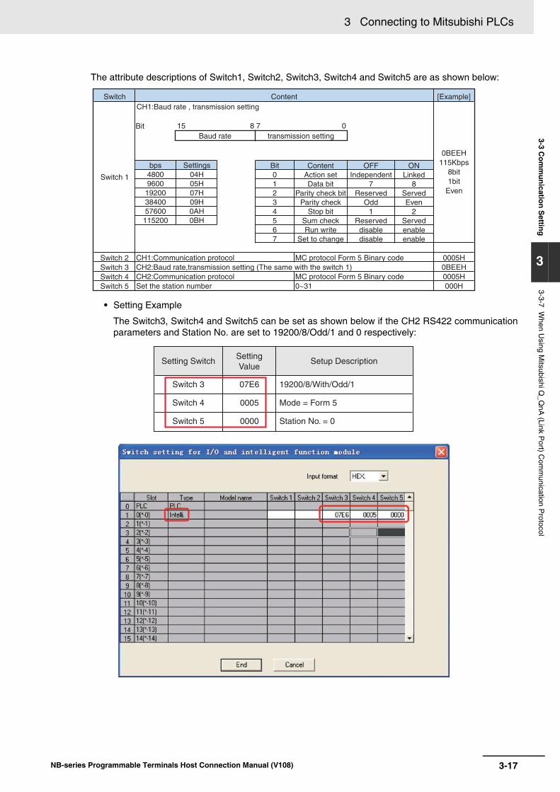
3-17
3 Connecting to Mitsubishi PLCs
NB-series Programmable Terminals Host Connection Manual (V108)
3-3 Com
munication S
etting
3
3-3-7 When U
sing Mitsubishi Q
_QnA
(Link Port) C
omm
unication Protocol
The attribute descriptions of Switch1, Switch2, Switch3, Switch4 and Switch5 are as shown below:
• Setting Example
The Switch3, Switch4 and Switch5 can be set as shown below if the CH2 RS422 communicationparameters and Station No. are set to 19200/8/Odd/1 and 0 respectively:
Bit 0 1 2 3 4 5 6 7
bps4800 9600
19200 38400 57600
115200
Settings04H 05H 07H 09H 0AH 0BH
Baud rate
CH1:Baud rate , transmission setting
Bit 15 8 7 0transmission setting
Switch
Switch 1
CH1:Communication protocolCH2:Baud rate,transmission setting (The same with the switch 1) CH2:Communication protocolSet the station number
Switch 2Switch 3Switch 4Switch 5
MC protocol Form 5 Binary code
MC protocol Form 5 Binary code0~31
0005H0BEEH0005H000H
0BEEH115Kbps
8bit1bit
Even
[Example]Content
ContentAction setData bit
Parity check bitParity check
Stop bitSum checkRun write
Set to change
OFFIndependent
7Reserved
Odd1
Reserveddisabledisable
ONLinked
8ServedEven
2Servedenableenable
Setting Switch
Switch 3
Switch 4
Switch 5
07E6
0005
0000
19200/8/With/Odd/1
Mode = Form 5
Station No. = 0
Setting Value
Setup Description

3 Connecting to Mitsubishi PLCs
3-18 NB-series Programmable Terminals Host Connection Manual (V108)
The Switch1, Switch2 and Switch5 can be set as shown below if the CH1 RS232 communication parameters and Station No. are set to 19200/8/Odd/1 and 0 respectively:
The difference between Mitsubishi Q_QnA (Link Port) protocol and Mitsubishi Melsec Q protocol:• Mitsubishi Q_QnA (Link Port) protocol features fast communication speed.• Mitsubishi Melsec Q protocol features slow communication speed.
Setting Switch
Switch 1
Switch 2
Switch 5
07E6
0005
0000
19200/8/With/Odd/1
Mode = Form 5
Station No. = 0
Setting Value
Setup Description

3-19
3 Connecting to Mitsubishi PLCs
NB-series Programmable Terminals Host Connection Manual (V108)
3-3 Com
munication S
etting
3
3-3-8 When U
sing Mitsubishi FX
Series E
thernet(TCP
Slave) C
omm
unication Protocol
The PT Network Settings are as shown below.
3-3-8 When Using Mitsubishi FX Series Ethernet(TCP Slave) Communication Protocol
PT Settings

3 Connecting to Mitsubishi PLCs
3-20 NB-series Programmable Terminals Host Connection Manual (V108)
The PLC Settings when using Communication Protocol of Mitsubishi FX Series Ethernet (TCP Slave) is as shown below.
1 Start-up Setting Tool, FX3U-ENET-L.
2 Click the [Operation Setting] to open [Ethernet Operation Setting].
Set the IP address to the same parameters as the PT settings.
Other settings should be the same as the dialog box as below.
PLC Settings

3-21
3 Connecting to Mitsubishi PLCs
NB-series Programmable Terminals Host Connection Manual (V108)
3-3 Com
munication S
etting
3
3-3-8 When U
sing Mitsubishi FX
Series E
thernet(TCP
Slave) C
omm
unication Protocol
3 Click the [Open Setting] to open the [Ethernet Open Setting].

3 Connecting to Mitsubishi PLCs
3-22 NB-series Programmable Terminals Host Connection Manual (V108)
The PT Network Settings are as shown below.
Note The Station No. is fixed to 255.
3-3-9 When Using Mitsubishi QnA 3EBin Ethernet (TCP Slave) Communication Protocol
PT Settings

3-23
3 Connecting to Mitsubishi PLCs
NB-series Programmable Terminals Host Connection Manual (V108)
3-3 Com
munication S
etting
3
3-3-9 When U
sing Mitsubishi Q
nA 3E
Bin E
thernet (TC
P S
lave) Com
munication P
rotocol
The PLC Settings when using Communication Protocol of Mitsubishi QnA 3EBin Ethernet (TCP Slave) is as shown below.
1 Double-click the [PLC Parameter] under [Project] of GX Works2 software.
2 [Q Parameter Setting] or [L Parameter Setting] dialog boxes are open.
Set the IP address to the same parameters as the PT settings.
Other settings should be the same as the dialog box as below.
PLC Settings

3 Connecting to Mitsubishi PLCs
3-24 NB-series Programmable Terminals Host Connection Manual (V108)
3 Click the [Open Setting] to open [Build-in Ethernet Port Open Setting] dialog box.
Set the parameters as the same with the dialog box as follows.
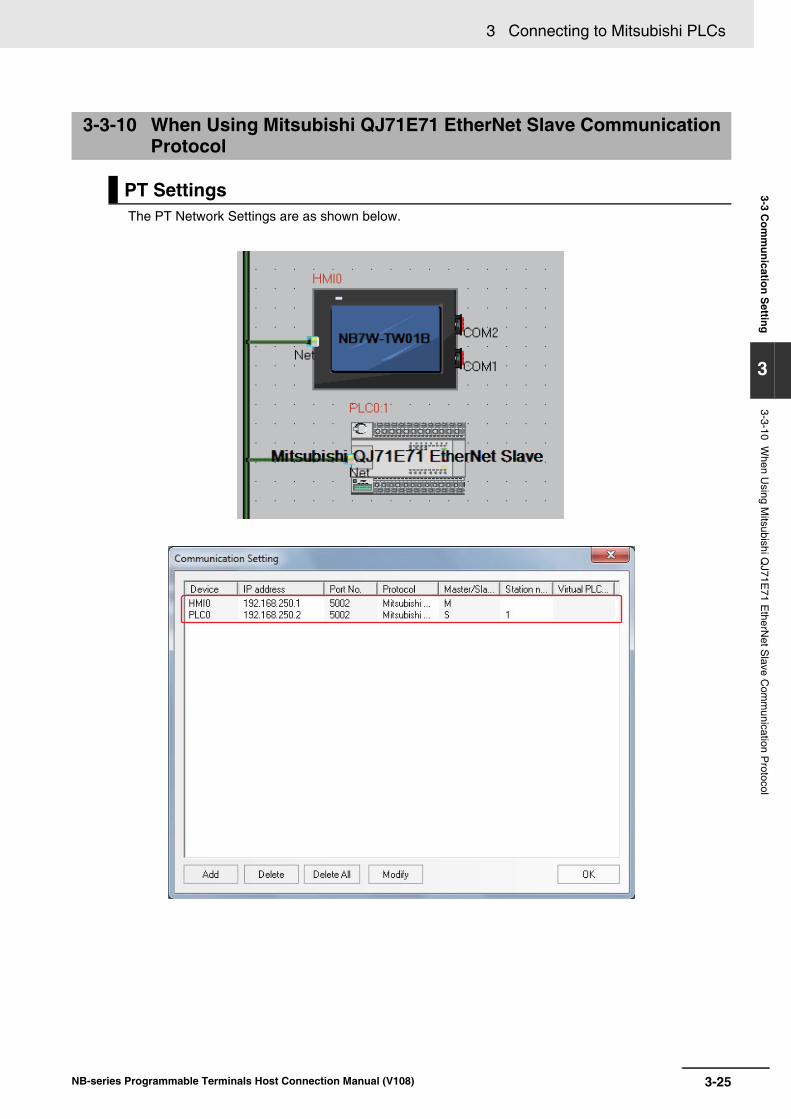
3-25
3 Connecting to Mitsubishi PLCs
NB-series Programmable Terminals Host Connection Manual (V108)
3-3 Com
munication S
etting
3
3-3-10 When U
sing Mitsubishi Q
J71E71 E
therNet S
lave Com
munication P
rotocol
The PT Network Settings are as shown below.
3-3-10 When Using Mitsubishi QJ71E71 EtherNet Slave Communication Protocol
PT Settings

3 Connecting to Mitsubishi PLCs
3-26 NB-series Programmable Terminals Host Connection Manual (V108)
PLC Settings when using Mitsubishi QJ71E71 EtherNet Slave Communication Protocol are as shown below.
1 Double-click the [Ethernet/CC IE/MELSECNET] under [Project] of GX Works2 software.
2 [Network Parameter] tab is opened.
Set the parameters as the same with the diagram as follows.
Note When connecting to NB, each parameter should be restricted to the ones as follows.Start I/O No.: 0000Network No.: 1Group No.: 0Station No.: 2 to 64Mode: Online
PLC Settings

3-27
3 Connecting to Mitsubishi PLCs
NB-series Programmable Terminals Host Connection Manual (V108)
3-3 Com
munication S
etting
3
3-3-10 When U
sing Mitsubishi Q
J71E71 E
therNet S
lave Com
munication P
rotocol
3 Click the [Operation Setting] to open [Ethernet Operation Setting].
Set the IP address to the same parameters as the PT settings.
Other settings should be the same as the dialog box as below.
4 Click the [Open Setting] to open the [Ethernet Open Setting] tab.
Set the IP address to the same parameters as the PT settings.
Other settings should be the same as the dialog box as below.

3 Connecting to Mitsubishi PLCs
3-28 NB-series Programmable Terminals Host Connection Manual (V108)
3-4 Supported Registers
Precautions for Correct UsePrecautions for Correct Use
The operation is not guaranteed when the area that does not exist phisically is accessed.
Additional Information
Address format description: D: decimal, O: octal, H: hexadecimal.
Mitsubishi FX1S Driver
Mitsubishi FX1N/2N/3GS Driver
Device Bit Address Word Address Format NotesInput Relay X 0-17 ------ OOOutput Relay Y 0-15 ------ OOInternal Relay M 0-511 ------ DDDTimer Contact T 0-63 ------ DDCounter Contact C 0-31 ------ DDData Contact D_bit 0.0-255.F ------ DDD.HState S 0-127 ------ DDDTimer Value ------ T_word 0-63 DDCounter Value ------ C_word 0-31 DDData Register ------ D_word 0-255 DDDSpecial Data Register ------ SD_word 8000-
8255DDDD
Counter Value ------ C_dword 235-255 DDD 32 bit device
Device Bit Address Word Address Format NotesInput Relay X 0-377 ------ OOOOutput Relay Y 0-377 ------ OOOInternal Relay M 0-3071 ------ DDDDTimer Contact T_bit 0-255 ------ DDDCounter Contact C_bit 0-199 ------ DDDSpecial Internal Relay SM 8000-8255 ------ DDDDState S 0-999 ------ DDDTimer Value ------ T_word 0-255 DDDCounter Value ------ C_word 0-199 DDDData Register ------ D 0-7999 DDDDSpecial Data Register ------ SD 8000-8255 DDDDCounter Value ------ C_dword 200-255 DDD 32 bit device

3-29
3 Connecting to Mitsubishi PLCs
NB-series Programmable Terminals Host Connection Manual (V108)
3-4 Supported R
egisters
3
Mitsubishi FX2N-10GM/20GM Driver
*1 does not support batch transmission while *2 supports batch transmission.
Mitsubishi FX3U Driver
*1 The operations accessed beyond the limit is not guaranteed.
Mitsubishi FX-485ADP/485BD/232BD (Multi-station) Driver
Device Bit Address Word Address Format Notes
Input Relay X 0-571 ------ OOO *1
Output Relay Y 0-571 ------ OOO *1
Internal Relay M 0-7999 ------ DDDD *1
Special Internal Relay SM 9000-9999 ------ DDDD *1
Data Register ------ D 0-7999 DDDD *2
Special Data Register ------ SD 9000-9999 DDDD *2
Special Data Register ------ FD 4000-4550 DDDD *2
Present position ------ CP_unit 0-1 D D9004-9005D9014-9015
Present position(converted into pulses)
------ CP_puls 0-1 D D9074-9075D9094-9095
Device Bit Address Word Address Format Notes
Input Relay X 0-764 ------ OOO
Output Relay Y 0-764 ------ OOO
Timer Contact T_bit 0-511 ------ DDD
Counter Contact C_bit 0-255 ------ DDD
Data Contact D_bit 0.0-7999.F ------ DDDD.H
State S 0-4095 ------ DDDD
Internal Relay M 0-7999 ------ DDDD *1
Special Internal Relay SM 8000-9999 ------ DDDD
Timer Value ------ T_word 0-511 DDD
Counter Value ------ C_word 0-199 DDD
Data Register ------ D_word 0-17999 DDDDD
Extension Register ------ R 0-32767 DDDDD
Special Data Register ------ SD 8000-9999 DDDD
Counter Value ------ C_dword 200-255 DDD 32 bit device
Device Bit Address Word Address Format Notes
Input Relay X 0-571 ------ OOO
Output Relay Y 0-571 ------ OOO
Timer Contact T_bit 0-511 ------ DDD
Counter Contact C_bit 0-255 ------ DDD
State S 0-4095 ------ DDDD
Internal Relay M 0-7679 ------ DDDD
Special Internal Relay SM 8000-8511 ------ DDDD
Timer Value ------ T_word 0-511 DDD
Counter Value ------ C_word 0-255 DDD
Data Register ------ D 0-7999 DDDD
FIle Register ------ R 0-32767 DDDDD
Special Data Register ------ SD 8000-8511 DDDD
Counter Value ------ C_dword 0-2047 DDDD 32 bit device
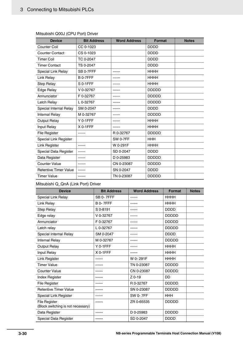
3 Connecting to Mitsubishi PLCs
3-30 NB-series Programmable Terminals Host Connection Manual (V108)
Mitsubishi Q00J (CPU Port) Driver
Mitsubishi Q_QnA (Link Port) Driver
Device Bit Address Word Address Format Notes
Counter Coil CC 0-1023 DDDD
Counter Contact CS 0-1023 DDDD
Timer Coil TC 0-2047 DDDD
Timer Contact TS 0-2047 DDDD
Special Link Relay SB 0-7FFF ------ HHHH
Link Relay B 0-7FFF ------ HHHH
Step Relay S 0-1FFF ------ HHHH
Edge Relay V 0-32767 ------ DDDDD
Annunciator F 0-32767 ------ DDDDD
Latch Relay L 0-32767 ------ DDDDD
Special Internal Relay SM 0-2047 ------ DDDD
Internal Relay M 0-32767 ------ DDDDD
Output Relay Y 0-1FFF ------ HHHH
Input Relay X 0-1FFF ------ HHHH
File Register ------ R 0-32767 DDDDD
Special Link Register SW 0-7FF HHH
Link Register ------ W 0-291F HHHH
Special Data Register ------ SD 0-2047 DDDD
Data Register ------ D 0-25983 DDDDD
Counter Value ------ CN 0-23087 DDDDD
Retentive Timer Value ------ SN 0-2047 DDDD
Timer Value ------ TN 0-23087 DDDDD
Device Bit Address Word Address Format Notes
Special Link Relay SB 0- 7FFF ------ HHHH
Link Relay B 0- 7FFF ------ HHHH
Step Relay S 0-8191 ------ DDDD
Edge relay V 0-32767 ------ DDDDD
Annunciator F 0-32767 ------ DDDDD
Latch relay L 0-32767 ------ DDDDD
Special Internal Relay SM 0-2047 ------ DDDD
Internal Relay M 0-32767 ------ DDDDD
Output Relay Y 0-1FFF ------ HHHH
Input Relay X 0-1FFF ------ HHHH
Link Register ------ W 0- 291F HHHH
Timer Value ------ TN 0-23087 DDDDD
Counter Value ------ CN 0-23087 DDDDD
Index Register ------ Z 0-19 DD
File Register ------ R 0-32767 DDDDD
Retentive Timer Value ------ SN 0-23087 DDDDD
Special Link Register ------ SW 0- 7FF HHH
File Register(Block switching is not necessary)
------ ZR 0-65535 DDDDD
Data Register ------ D 0-25983 DDDDD
Special Data Register ------ SD 0-2047 DDDD

3-31
3 Connecting to Mitsubishi PLCs
NB-series Programmable Terminals Host Connection Manual (V108)
3-4 Supported R
egisters
3
Mitsubishi Q series (CPU Port) Driver
*1 Supports only Q06UDH.
Mitsubishi Q06H Driver
Device Bit Address Word Address Format Notes
Special Link Relay SB 0-7FFF ------ HHHH
Link Relay B 0-7FFF ------ HHHH
Edge Relay V 0-32767 ------ DDDDD
Annunciator F 0-32767 ------ DDDDD
Latch Relay L 0-32767 ------ DDDDD
Special Internal Relay SM 0-2047 ------ DDDD
Internal Relay M 0-32767 ------ DDDDD
Output Relay Y 0-1FFF ------ HHHH
Input Relay X 0-1FFF ------ HHHH
Step Relay S 0 -8191 ------ DDDD
Link Register ------ W 0-291F HHHH
Timer Value ------ TN 0-23087 DDDDD
Counter Value ------ CN 0-23087 DDDDD
File Register ------ R 0-32767 DDDDD
Special Link Register ------ SW 0-7FF HHH
Data Register ------ D 0-25983 DDDDD
Special Data Register ------ SD 0-2047 DDDD
Index Register ------ Z 0-19 DD
File Register
(Block switching is not necessary)
------ ZR 0-4184063 DDDDDDD *1
Retentive Timer Value ------ SN 0-23087 DDDDD
Device Bit Address Word Address Format Notes
Special Link Relay SB 0-7FFF ------ HHHH
Link Relay B 0-7FFF ------ HHHH
Edge Relay V 0-32767 ------ DDDDD
Annunciator F 0-32767 ------ DDDDD
Latch Relay L 0-32767 ------ DDDDD
Special Internal Relay SM 0-2047 ------ DDDD
Internal Relay M 0-32767 ------ DDDDD
Output Relay Y 0-1FFF ------ HHHH
Input Relay X 0-1FFF ------ HHHH
Link Register ------ W 0-291F HHHH
Timer Value ------ TN 0-23087 DDDDD
Counter Value ------ CN 0-23087 DDDDD
File Register ------ R 0-32767 DDDDD
Special Link Register ------ SW 0-7FF HHH
Data Register ------ D 0-25983 DDDDD
Special Data Register ------ SD 0-2047 DDDD

3 Connecting to Mitsubishi PLCs
3-32 NB-series Programmable Terminals Host Connection Manual (V108)
Mitsubishi FX Series Ethernet (TCP Slave)
*1 The operations accessed beyond the limit is not guaranteed.
Mitsubishi QnA 3EBin Ethernet (TCP Slave) Driver
Device Bit Address Word Address Format Notes
Input Relay X 0-255 ------ OOO
Output Relay Y 0-255 ------ OOO
Timer Contact T_bit 0-511 ------ DDD
Counter Contact C_bit 0-255 ------ DDD
Data Contact D_bit 0-127999 ------ DDDDD
State S 0-4095 ------ DDDD
Internal Relay M 0-7679 ------ DDDD *1
Special Internal Relay SM 8000-8511 ------ DDDD
Timer Value ------ T_word 0-511 DDD
Counter Value ------ C_word 0-199 DDD
Data Register ------ D_word 0-7999 DDDD
Extension Register ------ R 0000-32767 DDDDD
Special Data Register ------ SD 8000-8511 DDDD
Counter Value ------ C_dword 200-255 DDD 32 bit device
Device Bit Address Word Address Format Notes
Input Relay X 0-3FFF ------ HHHH
Output Relay Y 0-3FFF ------ HHHH
Direct Input DX 0- 1FFF ------ HHHH
Direct Output DY 0- 1FFF ------ HHHH
Internal Relay M 0-61439 ------ DDDDD
Special Internal Relay SM 0-2255 ------ DDDD
Latch Relay L 0-32767 ------ DDDDD
Annunciator F 0-32767 ------ DDDDD
Edge Relay V 0-2047 ------ DDDDD
Link Relay B 0- EFFF ------ HHHH
Timer Contact TS 0-32767 ------ DDDDD
Timer Coil TC 0-32767 ------ DDDDD
Accumulated Timer (contact)
SS 0-32767 ------ DDDDD
Accumulated Timer (coil)
SC 0-32767 ------ DDDDD
Counter Contact CS 0-32767 ------ DDDDD
Counter Coil CC 0-32767 ------ DDDDD
Special Link Relay SB 0-7FFF ------ HHHH
Step Relay S 0-32767 ------ DDDDD
Data Register ------ D 0-61439 DDDDD
Special Data Register ------ SD 0-2255 DDDD
Link Register ------ W 0- EFFF HHHH
Special Link Register ------ SW 0-7FFF HHHH
Timer Value ------ TN 0-32767 DDDDD
Accumulated Timer (present value (PV))
------ SN 0-32767 DDDDD

3-33
3 Connecting to Mitsubishi PLCs
NB-series Programmable Terminals Host Connection Manual (V108)
3-4 Supported R
egisters
3Mitsubishi QJ71E71 Ethernet (TCP Slave) Driver
Counter Value ------ CN 0-32767 DDDDD
Index Register ------ Z 0-19 DD
File Register ------ R 0-32767 DDDDD
File Register(Block switching is not necessary)
------ ZR 0-4849663 DDDDDDD
Special Link Resister ------ SB 0-7FF0 HHHH
Link Resister ------ B 0-EFF0 HHHH
Input ------ X 0-3FF0 HHHH
Output ------ Y 0-3FF0 HHHH
Device Bit Address Word Address Format Notes
Input Relay X 0-2000 ------ HHHH
Output Relay Y 0-2000 ------ HHHH
Internal Relay M 0-32768 ------ DDDDD
Special Internal Relay SM 0-2048 ------ DDDD
Latch Relay L 0-32768 ------ DDDDD
Annunciator F 0-32768 ------ DDDDD
Edge Relay V 0-32768 ------ DDDDD
Link Relay B 0-8000 ------ HHHH
Timer Contact TS 0-23088 ------ DDDDD
Timer Coil TC 0-23088 ------ DDDDD
Accumulated Timer (contact)
SS 0-23088 ------ DDDDD
Accumulated Timer (coil)
SC 0-23088 ------ DDDDD
Counter Contact CS 0-23088 ------ DDDDD
Counter Coil CC 0-23088 ------ DDDDD
Special Link Relay SB 0-8000 ------ HHHH
Step Relay S 0-8192 ------ DDDD
Data Register ------ D 0-25984 DDDDD
Special Data Register ------ SD 0-2048 DDDD
Link Register ------ W 0- 2920 HHHH
Special Link Register ------ SW 0-800 HHH
Timer Value ------ TN 0-23088 DDDDD
Accumulated Timer (present value (PV))
------ SN 0-23088 DDDDD
Counter Value ------ CN 0-23088 DDDDD
File Register ------ R 0-32768 DDDDD
File Register(Block switching is not necessary)
------ ZR 0-1042432 DDDDDDD
Device Bit Address Word Address Format Notes
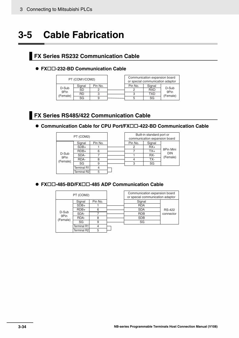
3 Connecting to Mitsubishi PLCs
3-34 NB-series Programmable Terminals Host Connection Manual (V108)
3-5 Cable Fabrication
FX-232-BD Communication Cable
Communication Cable for CPU Port/FX-422-BD Communication Cable
FX-485-BD/FX-485 ADP Communication Cable
FX Series RS232 Communication Cable
FX Series RS485/422 Communication Cable
PT (COM1/COM2)
Pin No.239
SignalSDRDSG
D-Sub 9Pin
(Female)
Communication expansion boardor special communication adaptorPin No.
235
SignalRXDTXDSG
D-Sub 9Pin
(Female)
PT (COM2)
Pin No.167
SignalSDB+RDB+SDA-D-Sub
9Pin(Female)
Built-in standard port orcommunication expansion boardPin No.
271
SignalRX+TX+RX-
8Pin Mini DIN
(Female)89
RDA-SG
45
Terminal R1Terminal R2
43
TX-SG
45
Terminal R1Terminal R2
PT (COM2)
Pin No.167
SignalSDB+RDB+SDA-D-Sub
9Pin(Female)
Communication expansion boardor special communication adaptor
SignalRDASDARDB
RS-422connector
89
RDA-SG
SDBSG

3-35
3 Connecting to Mitsubishi PLCs
NB-series Programmable Terminals Host Connection Manual (V108)
3-5 Cable Fabrication
3
Communication Cable for CPU Port (Except Q00UJ CPU and L02S CPU)
Communication Cable for CPU Port (Q00UJ CPU and L02S CPU)For the communication with the PT, use RS-232 cable (QC30R2) to connect the PC - sequencerCPU manufactured by Mitsubishi Electric.
RS232 communication cable for C24 Serial Communication Module
RS422 Communication Cable for C24 Serial Communication Module
Use Twisted Pair Cable to connect. Refer to Ethernet communication specifications in A-1-3 Communication Specifications in the NB-series Programmable Terminals Setup Manual (Cat. No. V107).
Q Series RS232 Communication Cable
Q-Series RS485/422 Communication Cable
Ethernet Communication Cable
SG
PT (COM1/COM2)Pin No.
239
SignalSDRDSG
D-Sub 9Pin
(Female)
PLCPin No.
123
SignalRXDTXD
6Pin Mini DIN
(Female)
PT (COM1/COM2)Pin No.
239
SignalSDRDSG
D-Sub 9Pin
(Female)
programming cable for Mitsubishi Q series PLC
Pin No.325
SignalRDSDSG
D-Sub 9Pin
(Female)46
DRER
PT (COM1/COM2)Pin No.
239
SignalSDRDSG
D-Sub 9Pin
(Female)
C24 serial communication modulePin No.
235
SignalRXDTXDSG D-Sub
9Pin(Female)
1467
CDDTRDSRRTS
8 CTS
D-Sub 9Pin
(Female)
PT (COM2)Pin No.
167
SignalSDB+RDB+SDA-
C24 serial communication moduleSignalRDASDARDB
RS-422connector
89
RDA-SG
SDBSG
45
Terminal R1 Terminal R2

3 Connecting to Mitsubishi PLCs
3-36 NB-series Programmable Terminals Host Connection Manual (V108)
4-1NB-series Programmable Terminals Host Connection Manual (V108)
4This section describes the connection to Schneider PLCs.
4-1 Serial Port Communication . . . . . . . . . . . . . . . . . . . . . . . . . . . . . . . . . . . . . . 4-2
4-2 Communication Parameters and Cable Fabrication . . . . . . . . . . . . . . . . . . 4-3
4-3 Communication Parameter Setting . . . . . . . . . . . . . . . . . . . . . . . . . . . . . . . 4-4
4-4 Supported Registers . . . . . . . . . . . . . . . . . . . . . . . . . . . . . . . . . . . . . . . . . . 4-13
4-5 Cable Fabrication . . . . . . . . . . . . . . . . . . . . . . . . . . . . . . . . . . . . . . . . . . . . . 4-14
Connecting to Schneider PLCs
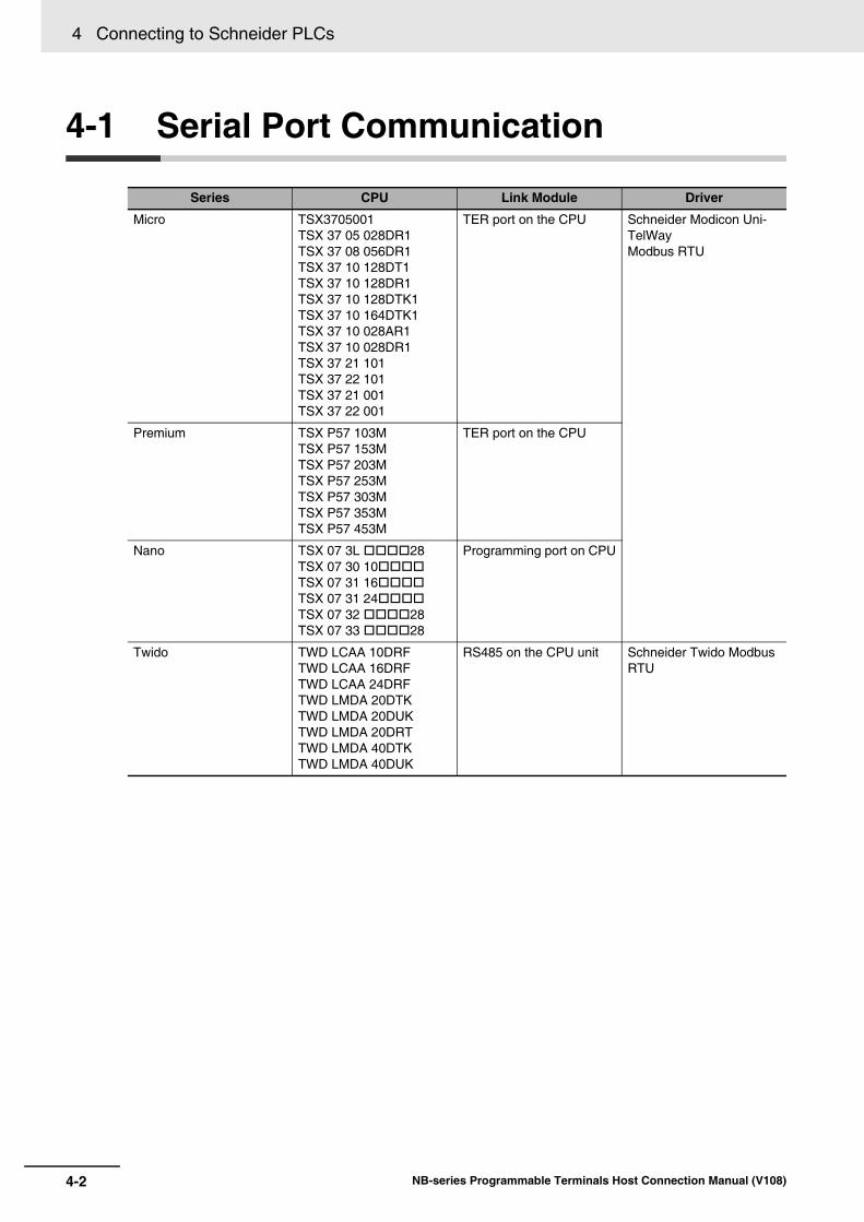
4 Connecting to Schneider PLCs
4-2 NB-series Programmable Terminals Host Connection Manual (V108)
4-1 Serial Port Communication
Series CPU Link Module Driver
Micro TSX3705001TSX 37 05 028DR1TSX 37 08 056DR1TSX 37 10 128DT1TSX 37 10 128DR1TSX 37 10 128DTK1TSX 37 10 164DTK1TSX 37 10 028AR1TSX 37 10 028DR1TSX 37 21 101TSX 37 22 101TSX 37 21 001TSX 37 22 001
TER port on the CPU Schneider Modicon Uni-TelWayModbus RTU
Premium TSX P57 103MTSX P57 153MTSX P57 203MTSX P57 253MTSX P57 303MTSX P57 353MTSX P57 453M
TER port on the CPU
Nano TSX 07 3L 28TSX 07 30 10TSX 07 31 16TSX 07 31 24TSX 07 32 28TSX 07 33 28
Programming port on CPU
Twido TWD LCAA 10DRFTWD LCAA 16DRFTWD LCAA 24DRFTWD LMDA 20DTKTWD LMDA 20DUKTWD LMDA 20DRTTWD LMDA 40DTKTWD LMDA 40DUK
RS485 on the CPU unit Schneider Twido Modbus RTU

4-3
4 Connecting to Schneider PLCs
NB-series Programmable Terminals Host Connection Manual (V108)
4-2 Com
munication P
arameters and C
able Fabrication
4
4-2 Communication Parameters and Cable Fabrication
Series CPU Link Module Driver COMM
Type Parameter Cable
Modicon TSX
TSX3705001TSX3705001TSX 37 05 028DR1TSX 37 08 056DR1TSX 37 10 128DT1TSX 37 10 128DR1TSX 37 10 128DTK1TSX 37 10 164DTK1TSX 37 10 028AR1TSX 37 10 028DR1TSX 37 21 101TSX 37 22 101TSX 37 21 001TSX 37 22 001
RS485 on the CPU unit
Schneider Modicon Uni-TelWay
RS232 Refer to Section 4-3
Self-made cable required
RS485
TSX3705001TSX3705001TSX 37 05 028DR1TSX 37 08 056DR1TSX 37 10 128DT1TSX 37 10 128DR1TSX 37 10 128DTK1TSX 37 10 164DTK1TSX 37 10 028AR1TSX 37 10 028DR1TSX 37 21 101TSX 37 22 101TSX 37 21 001TSX 37 22 001
RS485 on the CPU unit
Modbus RTU
RS232
RS485
Twido TWD LCAA 10DRFTWD LCAA 16DRFTWD LCAA 24DRFTWD LMDA 20DTKTWD LMDA 20DUKTWD LMDA 20DRTTWD LMDA 40DTKTWD LMDA 40DUK
RS485 on the CPU unit
Scheneider Twido Modbus RTU
RS232
RS485
4 Connecting to Schneider PLCs
4-4 NB-series Programmable Terminals Host Connection Manual (V108)
4-3 Communication Parameter Setting
When Using Schneider Modicon Uni-TelWay ProtocolPT default communication parameters: 19200bps (Baud Rate), 8 (Data Bit), odd (Parity Check), 1(Stop Bit) and 4 (PLC Station No.)
RS232 Communication
RS485 Communication
PT Settings

4-5
4 Connecting to Schneider PLCs
NB-series Programmable Terminals Host Connection Manual (V108)
4-3 Com
munication P
arameter S
etting
4
When Using Modbus RTU ProtocolPT default communication parameters: 9600bps (Baud Rate), 8 (Data Bit), even (Parity Check), 1(Stop Bit) and 1 (PLC Station No.)
RS232 Communication
RS485 Communication
4 Connecting to Schneider PLCs
4-6 NB-series Programmable Terminals Host Connection Manual (V108)
PL7 Software Setting
1 Open “Programs” menu - Select [XWAY Driver Manager] from Modicon Telemecanique:
2 Select [UNITELWAY Driver] tab and push [Configuration] in the dialog box and finally select [Edit] in the following dialog box to modify the related setttings of the communications.
PLC Settings

4-7
4 Connecting to Schneider PLCs
NB-series Programmable Terminals Host Connection Manual (V108)
4-3 Com
munication P
arameter S
etting
4
3 The following prompt information will appear after the [OK] button is clicked:

4 Connecting to Schneider PLCs
4-8 NB-series Programmable Terminals Host Connection Manual (V108)
4 Click [XWAY Test][Connect] and the Connected prompt information will appear when the connection is successful.
5 Open PL7 SoftwareNewClick [Hardware Configuration] in [STATION]Double-click [comm] in popup window.

4-9
4 Connecting to Schneider PLCs
NB-series Programmable Terminals Host Connection Manual (V108)
4-3 Com
munication P
arameter S
etting
4
The settings are as shown below if Schneider Modicon Uni-TelWay Protocol is used:
The settings are shown as below if Modbus RTU Protocol is used:
6 Download the project to PLC after the settings are completed.

4 Connecting to Schneider PLCs
4-10 NB-series Programmable Terminals Host Connection Manual (V108)
When Using Schneider Twido Modbus RTU ProtocolPT default communication parameters: 19200bps (Baud Rate), 8 (Data Bit), none (Parity Check), 1(Stop Bit) and 1 (PLC Station No.)
RS485 Communication
RS232 Communication
PT Settings

4-11
4 Connecting to Schneider PLCs
NB-series Programmable Terminals Host Connection Manual (V108)
4-3 Com
munication P
arameter S
etting
4
When Using Schneider Twido Modbus RTU ProtocolNote The memory addresses of Twido are under dynamic management, which may lead to communication
failure when address link is available. Refer to the setting method of PLC as follows and set the words or bits correctly. It is recommended the user to add a line of ladder program in the following item of 3 to the end of the ladder program created by the user. If the settings are mistaken, the PLC cannot communicate with the PT device.
1 Controller Communications Setup
PLC Settings

4 Connecting to Schneider PLCs
4-12 NB-series Programmable Terminals Host Connection Manual (V108)
2 Expand the range of word memory address. Then change the [Auto] option in the [Assigned] column after selecting [Controller], [Used Memory] and [Edit] to a larger variable than internal memory and download the settings to the PLC.It is assumed that the “Auto” is set to 3000 as shown below, all addresses before %MW3000 can perform the data swap.
3 Extend the range of open bit address and drive the coil with a maximum address through the programming.It is assumed that a %M127 coil is driven as shown below, all addresses before %M127 can perform the data swap.
0%M0 %M127
4-13
4 Connecting to Schneider PLCs
NB-series Programmable Terminals Host Connection Manual (V108)
4-4 Supported R
egisters
4
4-4 Supported Registers
Modicon TSX
Twido
Note The registers M and MW in TWIDO software correspond to 0X and 4X of PT respectively. The address offset of PT and PLC is 1.Do not use 1X and 3X of PT for there are no registers in TWIDO software corresponding to them. The PT address must be “PLC address + 1”. For example: The M0 in PLC corresponds to 0X1 of PT. Address format description: D: decimal, O: octonary, H: hexadecimal.
Device Bit Address Word Address Format Notes
System Internal Nodes S00000-32767 ------ DDDDD
Internal Auxiliary Nodes M00000-32767 ------ DDDDD
Data Register Bit Nodes MW.B0000-9999.F ------ DDDD.H
Data Registers ------ MW0000-7999 DDDD
Data Registers (32-bit) ------ MD0000-7999 DDDD
Device Bit Address Word Address Format Notes
Internal Auxiliary Nodes 0X 1-9999 ------ DDDD
1X 1-9999 ------ DDDD
------ 3X 1-9999 DDDD
Data Registers ------ 4X 1-9999 DDDD
4 Connecting to Schneider PLCs
4-14 NB-series Programmable Terminals Host Connection Manual (V108)
4-5 Cable Fabrication
RS232 Communication CableUse serial port programming cable manufactured by Schneider directly to communicate with PT.
Note Direct the middle cable knob to position 2 and add a RS232 cable directly between the PT and programming cable.
RS485 Communication Cable
RS232 Communication CableUse serial port programming cable manufactured by Schneider directly to communicate with PT.
Note Direct the middle cable knob to position 3
RS485 Communication Cable
RS232 Communication CableUse serial port communication cable manufactured by Schneider directly to communicate with PT.
RS485 Communication Cable
When Using Schneider Modicon Uni-TelWay Protocol
When Using Modbus RTU Protocol
When Using Schneider Twido Modbus RTU Protocol
PT (COM2)Pin No.
689
SignalRDB+RDA-SG
D-Sub 9Pin
(Female)
PLCPin No.
127
SignalD+D-
GND
8Pin Mini DIN
(Female)
45
Terminal R1 Terminal R2
PT (COM2)Pin No.
689
SignalRDB+RDA-SG
D-Sub 9Pin
(Female)
PLCPin No.
125
SignalD+D-
DPT
8Pin Mini DIN
(Female)7 GND4
5Terminal R1 Terminal R2
PT (COM2)Pin No.
689
SignalRDB+RDA-SG
D-Sub 9Pin
(Female)
PLCPin No.
125
SignalA+B-
DPT
8Pin Mini DIN
(Female)7 GND4
5Terminal R1 Terminal R2

5-1NB-series Programmable Terminals Host Connection Manual (V108)
5
This section describes the connection on Modbus protocol.
5-1 Serial Port and Ethernet . . . . . . . . . . . . . . . . . . . . . . . . . . . . . . . . . . . . . . . . 5-2
5-2 Communication Parameters and Cable Fabrication . . . . . . . . . . . . . . . . . . 5-3
5-3 Communication Parameter Setting . . . . . . . . . . . . . . . . . . . . . . . . . . . . . . . 5-4
5-4 Supported Registers . . . . . . . . . . . . . . . . . . . . . . . . . . . . . . . . . . . . . . . . . . . 5-7
5-5 Cable Fabrication . . . . . . . . . . . . . . . . . . . . . . . . . . . . . . . . . . . . . . . . . . . . . . 5-9
5-6 Modbus Protocol . . . . . . . . . . . . . . . . . . . . . . . . . . . . . . . . . . . . . . . . . . . . . 5-105-6-1 Introduction to Modbus Protocol . . . . . . . . . . . . . . . . . . . . . . . . . . . . . . . . . . 5-105-6-2 When NB adopts Modbus TCP protocol (Master/Slave mode) . . . . . . . . . . . 5-11
5-7 Example of NB as Modbus Slave . . . . . . . . . . . . . . . . . . . . . . . . . . . . . . . . 5-12
5-8 Example of connection using Modbus TCP protocol . . . . . . . . . . . . . . . . 5-15
5-9 Example of E5CC/E5EC, 3G3MX2 connection using Modbus RTU Extend Protocol . . . . . . . . . . . . . . . . . . . . . . . . . . . . . . . . . . . . . . . . . . . . . . . . . . . . . 5-16
5-10 Example of Power PMAC Motion Controller using Modbus TCP Slave Protocol . . . . . . . . . . . . . . . . . . . . . . . . . . . . . . . . . . . . . . . . . . . . . . . . . . . . . 5-18
Modbus Connection

5 Modbus Connection
5-2 NB-series Programmable Terminals Host Connection Manual (V108)
5-1 Serial Port and Ethernet
*1 Connectable 3G3MX2 Series models are 3G3MX2-V1 or higher that support Endian data conversion. Other models cannot handle 2-word data properly.
Series CPU Link Module SIO Type Driver
Modbus RTU Modbus Compatible External Device
RS232 on the CPU unit - Modbus RTU
Modbus RTU Modicon_BE
RS422 on the CPU unit -
RS485 on the CPU unit -
Modbus RTU Extend RS232 on the CPU unit - Modbus RTU Extend
RS422 on the CPU unit -
RS485 on the CPU unit -
Modbus RTU Slave RS232 on the CPU unit - Modbus RTU Slave
RS422 on the CPU unit -
RS485 on the CPU unit -
Modbus ASCII RS232 on the CPU unit - Modbus ASCII
RS422 on the CPU unit -
RS485 on the CPU unit -
Modbus TCP - Ethernet Modbus TCP
Modbus TCP Slave - Ethernet Modbus TCP Slave
Modbus RTU Extend Thermoregulator (Degital Regulator) E5CC/E5EC (RS485 Connection)
RS485 - Modbus RTU Extend
Modbus RTU Extend Multi-function Compact Inverter 3G3MX2 *1
RS485 - Modbus RTU Extend
Modbus TCP Slave Power PMAC Etherlite
- Ethernet Modbus TCP Slave

5-3
5 Modbus Connection
NB-series Programmable Terminals Host Connection Manual (V108)
5-2 Com
munication P
arameters and C
able Fabrication
5
5-2 Communication Parameters and Cable Fabrication
Series CPU Link Module COMM Type Parameter Cable
Modbus RTU Modbus Compatible External Device
RS232 on the CPU unit
RS232 Refer to Section 5-3 Self-made cable required
RS422 on the CPU unit
RS422
RS485 on the CPU unit
RS485
Modbus RTU Extend
RS232 on the CPU unit
RS232
RS422 on the CPU unit
RS422
RS485 on the CPU unit
RS485
Modbus RTU Slave
RS232 on the CPU unit
RS232
RS422 on the CPU unit
RS422
RS485 on the CPU unit
RS485
Modbus ASCII RS232 on the CPU unit
RS232
RS422 on the CPU unit
RS422
RS485 on the CPU unit
RS485
Modbus TCP - Ethernet Network cable
Modbus TCP Slave
- Ethernet Network cable
Modbus RTU Extend
Thermoregulator (Degital Regulator) E5CC/E5EC (RS485 Connection)
RS485 RS485 Self-made cable required
Modbus RTU Extend
Multi-function Compact Inverter 3G3MX2
RS485 RS485 Self-made cable required
Modbus TCP Slave
Power PMAC Etherlite
- Ethernet Network cable
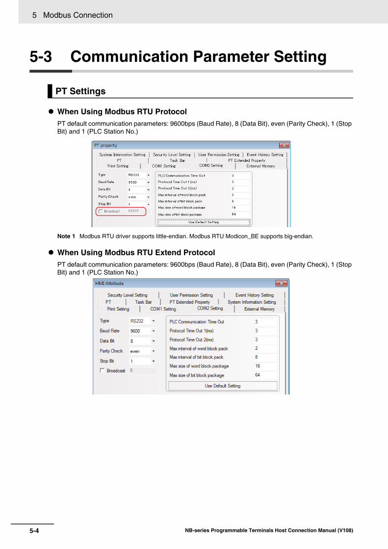
5 Modbus Connection
5-4 NB-series Programmable Terminals Host Connection Manual (V108)
5-3 Communication Parameter Setting
When Using Modbus RTU ProtocolPT default communication parameters: 9600bps (Baud Rate), 8 (Data Bit), even (Parity Check), 1 (Stop Bit) and 1 (PLC Station No.)
Note 1 Modbus RTU driver supports little-endian. Modbus RTU Modicon_BE supports big-endian.
When Using Modbus RTU Extend Protocol PT default communication parameters: 9600bps (Baud Rate), 8 (Data Bit), even (Parity Check), 1 (Stop Bit) and 1 (PLC Station No.)
PT Settings

5-5
5 Modbus Connection
NB-series Programmable Terminals Host Connection Manual (V108)
5-3 Com
munication P
arameter S
etting
5
When Using Modbus RTU Slave Protocol PT default communication parameters: 9600bps (Baud Rate), 8 (Data Bit), even (Parity Check), 1 (Stop Bit) and 1 (PLC Station No.)
When Using Modbus ASCII Protocol PT default communication parameters: 9600bps (Baud Rate), 8 (Data Bit), even (Parity Check), 1 (Stop Bit) and 1 (PLC Station No.)

5 Modbus Connection
5-6 NB-series Programmable Terminals Host Connection Manual (V108)
When Using Modbus TCP Slave ProtocolPT serves as the master, the network configuration is as follows.
When Using Modbus TCP ProtocolPT serves as the slave, the network configuration is as follows.
Refer to 5-7 Example of NB as Modbus Slave for example.

5-7
5 Modbus Connection
NB-series Programmable Terminals Host Connection Manual (V108)
5-4 Supported R
egisters
5
5-4 Supported Registers
Modbus RTU
Modbus RTU Modicon_BE
Note 1 The value which endian of 4x is reversed by the unit of Word is set to 5x.Example: When 0x1234 is stored to 4X, 0x3412 is set to 5X.
2 The values which endian of 4X and 5X is reversed by the unit of Double Word are set to 4X-DINV and 5X-DINV, respectively.Example: When 0x12345678 is stored to 4X, 0x56781234 is set to 4X-DINV.
Modbus RTU Extend
Note 1 The value which endian of 4X is reversed by the unit of Word is set to 5X.Example: When 0x1234 is stored to 4X, 0x3412 is set to 5X.
2 The values which endian of 3X and 4X is reversed by the unit of Double Word are set to 3X-DINV and 4X-DINV, respectively.Example: When 0x12345678 is stored to 3X, 0x56781234 is set to 3X-DINV.
3 When connecting to E5CC/E5EC, use 4X for the address since all addresses are handled as holding reg-ister.
Device Bit Address Word Address Format NotesSystem Internal/External Output Nodes
0X 1-65535 ------ DDDDD
System Internal/External Input Nodes
1X 1-65535 ------ DDDDD
Analog Input Data Registers ------ 3X 1-65535 DDDDD
Data Registers ------ 4X 1-65535 DDDDD
Device Bit Address Word Address Format NotesSystem Internal/External Output Nodes
0X 1-65535 ------ DDDDD
System Internal/External Input Nodes
1X 1-65535 ------ DDDDD
Analog Input Data Registers ------ 3X 1-65535 DDDDD
Data Registers ------ 4X 1-65535 DDDDD
Data Registers ------ 5X 1-65535 DDDDD
Data Registers ------ 4X-DINV 1-65535 DDDDD 32 bit device
Data Registers ------ 5X-DINV 1-65535 DDDDD 32 bit device
Device Bit Address Word Address Format NotesSystem Internal/External Output Nodes
0X 1-65535 ------ DDDDD
System Internal/External Input Nodes
1X 1-65535 ------ DDDDD
Analog Input Data Nodes 3X_bit 1.00-65535.15
------ DDDDD.DD
Data Nodes 4X_bit 1.00-65536.15
------ DDDDD.DD
4X Single Write Data Nodes 6X_bit 1.00-65535.15
------ DDDDD.DD
Analog Input Data Registers ------ 3X 1-65535 DDDDD
Data Registers ------ 4X 1-65536 DDDDD
Data Registers ------ 5X 1-65535 DDDDD
4X Single Write ------ 6X 1-65535 DDDDD
Data Registers ------ 3X-DINV 1-65535 DDDDD 32 bit device
Data Registers ------ 4X-DINV 1-65535 DDDDD 32 bit device

5 Modbus Connection
5-8 NB-series Programmable Terminals Host Connection Manual (V108)
Modbus RTU Slave
Modbus ASCII
Modbus TCP Slave
Note Address format description: D: decimal, O: octonary, H: hexadecimal.
Device Bit Address Word Address Format Notes
System Internal/External Output Nodes
LB 0-8999 ------ DDDDD Mapping to 0x 1~9000
Data Registers ------ LB 0-8999 DDDDD Mapping to 4x 1~9000
Device Bit Address Word Address Format Notes
System Internal/External Output Nodes
0X 1-65535 ------ DDDDD
System Internal/External Input Nodes
1X 1-65535 ------ DDDDD
Analog Input Data Registers ------ 3X 1-65535 DDDDD
Data Registers ------ 3X 1-65535 DDDDD
Device Bit Address Word Address Format Notes
System Internal/External Output Nodes
0X 1-65535 ------ DDDDD
System Internal/External Input Nodes
1X1-65535 ------ DDDDD
Analog Input Data Nodes 3X_bit 1.00-65535.15
------ DDDDD.DD
Data Nodes 4X_bit 1.00-65535.15
------ DDDDD.DD
Analog Input Data Registers ------ 3X1-65535 DDDDD
Data Registers ------ 4X1-65535 DDDDD
Data Registers ------ 4X-DINV 1-65535 DDDDD
Data Registers ------ 3X-DINV 1-65535 DDDDD

5-9
5 Modbus Connection
NB-series Programmable Terminals Host Connection Manual (V108)
5-5 Cable Fabrication
5
5-5 Cable Fabrication
RS232 Communication Cable
RS422 Communication Cable
RS485 Communication Cable (PLC)
RS485 Communication Cable (E5CC/E5EC)
RS485 Communication Cable (3G3MX2)
Ethernet Communication CableUse Twisted Pair Cable to connect. Refer to Ethernet communication specifications in A-1-3 Com-munication Specifications in the NB-series Programmable Terminals Setup Manual (Cat. No. V107).
PT (COM1/COM2)Pin No.
239
SignalSDRDSG
D-Sub 9Pin
(Female)
PLCPin No.
329
SignalRXDTXDGND
D-Sub 9Pin
PT (COM2)
Pin No.167
SignalSDB+RDB+SDA-
D-Sub 9Pin
(Female)
Communication expansion boardor special communication adaptor
SignalRDB+SDB+RDA-
RS-422 connector
89
RDA-SG
SDA-SG
PT (COM2)Pin No.
689
SignalRDB+RDA-SG
D-Sub 9Pin
(Female)
PLCSignal
SDB+/RDB+SDA-/RDA-
SG
RS-485connector
PT (COM2)Pin No.
68
SignalRDB+RDA-
D-Sub 9Pin
(Female)
E5CC/E5ECSignalB(+)A(-)
RS-485connector
PT (COM2)Pin No.
68
SignalRDB+RDA-
D-Sub 9Pin
(Female)
3G3MX2SignalRS+RS-
RS-485connector

5 Modbus Connection
5-10 NB-series Programmable Terminals Host Connection Manual (V108)
5-6 Modbus Protocol
Modbus functions as a request-response protocol which provides the service specified by function codes.
Modbus protocol such as ASCII, RTU, and TCP does not specify the physical layer, but defines the message frame and is available to communicate with the Controllers through varied networks. In ASCII mode and RTU mode, the protocol is composed of the each combination of message and data, or command and response. The data communications of Modbus adopt master-slave mode. In the mode, first of all, the master sends a message and the slave receives the message, followed by the slave replies the data to the request by the master.
As the master can also send the data directly to the slave to change the data of the slave, that means the master and the slave can perform bidirectional read and write.
When the PTs of NB series performs the communications following the Modbus protocol, it is performed in accordance with Modbus communications procedure.
Common format of message frame is shown as follows.
Address code Data field of the message frame is two characters when the transmission mode is ASCII and eightbits when it is RTU. Addresses of the slave are ranged from 0 to 247 (written by decimal) andaddresses of each device are allocated from 1 to 247. The master device select the slave devicethrough the data field of the message in which the addresses of the slave communicating with themaster are stored. When the slave replies the message, in order to recognize which slave replied tothe message, the addresses replied from the slave are stored in the data field of the response mes-sage. Address 0 is used as a broadcast address which can be recognized by all the slave devices.
Function code
5-6-1 Introduction to Modbus Protocol
Address code Function code Data area Error checking code
8 bits 8 bits N × 8 bits 16 bits
Modbus Function Code Name Function Corresponding
Address Type
01 Read coil status Reads the bit data (N bits) 0x
02 Read input discrete value
Reads the bit data 1x
03 Read multiple registers Reads the integer type/character type/status word /floating-point data (N words)
4x
04 Read input registers Reads the integer type/status word/floating-point type data
3x
05 Write single coil Writes the bit data (one bit) 0x
06 Write single register Writes the integer type/character type/status word /floating-point data (one word)
4x
15 Write multiple coils Writes the bit data (N bits) 0x
16 Write multiple registers Writes the integer type/character type/status word /floating-point data (N words)
4x

5-11
5 Modbus Connection
NB-series Programmable Terminals Host Connection Manual (V108)
5-6 Modbus P
rotocol
5
5-6-2 When N
B adopts M
odbus TCP
protocol (Master/S
lave mode)
The read/write function codes corresponding to each mode are as follows:
* This function code is not supported when the PT operates as the slave.
Data area The data area includes the required data from PT or replied data from the devices such as variables, referred addresses, and setting values. For instance, when the PT is informed of memory read by the function code, which memory and which area of the memory should be read are necessary to be specified in the data field. The specified addresses and data type are varied according to the slave specifications.
Error checking code Modbus protocol checks if the message frame could be received correctly. Besides the parity check of serial protocol, it is checked using LRC in ASCII mode or 16 bits CRC in RTU mode. In TCP mode, only parity check is performed.
When the PLC and the PT are connected via the Modbus protocol, 2 situations exist depending on the master and slave statuses of the devices.
(1) PT is the master and PLC is the slave
The PT as the master and the PLC as the slave communicate through the Modbus TCP protocol. The PLC is operated in slave mode of Modbus TCP protocol, and also performs mapping on the 0X, 1X, 3X and 4X registers (hereof, the 0X and 1X are bit registers, and the 3X, while 3X and 4X are word registers.)
(2) PLC is the master, and PT is the slave
The PLC as the master and the PT as the slave communicate through the Modbus TCP protocol. The PLC is operated as the master in the Modbus TCP protocol. The PT performs mapping LB on the 0X and LW on the 4X registers. These addresses can be written and read by the PLC.
The corresponding relations of the registers are as below:
Mode
Function
Modbus RTU, Modbus RTU Extend, Modbus RTU Slave, Modbus ASCII Modbus TCP
Bit Word Bit Word
Read 01, 02 03, 04 01, 02* 03, 04*
Write 05, 15 06, 16 05, 15 06, 16
5-6-2 When NB adopts Modbus TCP protocol (Master/Slave mode)
Method Mater/Slave Protocol used Descriptions
1 PT as the master Modbus TCP The PT accesses the 0X, 1X, 3X and 4X registers mapped out by the PLC.
PLC as the slave Modbus TCP Slave
2 PT as the slave Modbus TCP Slave The PT local address LW is mapped as the 4X register, and the LB as the 0X register.
PLC as the master Modbus TCP
Modbus register address range The corresponding PT local address range
0X(1---9000) LB(0---8999)
4X(1---9000) LW(0---8999)

5 Modbus Connection
5-12 NB-series Programmable Terminals Host Connection Manual (V108)
5-7 Example of NB as Modbus Slave
Communication by Modbus RTU Slave protocolSystem description: Use CP1E-N30D- (30-point I/O type) as Modbus master and an NB Unit as Modbus slave to perform the communication.
CP1E-N30D- should connect to CP1W-CIF11 module functioning as RS485 communication port.
Use CX-Programmer to configure the peripheral port.
Make the communication settings as follows: 9600, 8, 1, Even and Modbus-RTU simple master.
PLC Setting
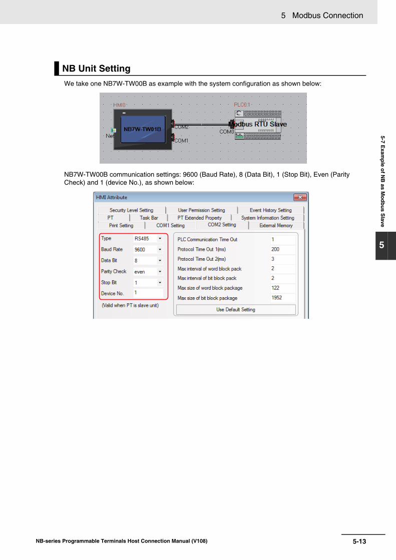
5-13
5 Modbus Connection
NB-series Programmable Terminals Host Connection Manual (V108)
5-7 Exam
ple of NB
as Modbus S
lave
5
We take one NB7W-TW00B as example with the system configuration as shown below:
NB7W-TW00B communication settings: 9600 (Baud Rate), 8 (Data Bit), 1 (Stop Bit), Even (Parity Check) and 1 (device No.), as shown below:
NB Unit Setting
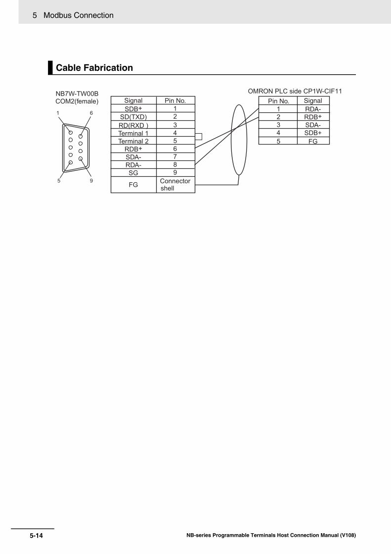
5 Modbus Connection
5-14 NB-series Programmable Terminals Host Connection Manual (V108)
Cable Fabrication
1 6
95
NB7W-TW00BCOM2(female) Signal
SDB+SD(TXD)RD(RXD )Terminal 1Terminal 2
RDB+SDA-RDA-SG
FG
Pin No.123456789
Connectorshell
OMRON PLC side CP1W-CIF11Pin No.
12345
SignalRDA-RDB+SDA-SDB+
FG

5-15
5 Modbus Connection
NB-series Programmable Terminals Host Connection Manual (V108)
5-8 Exam
ple of connection using Modbus TC
P protocol
5
5-8 Example of connection using Modbus TCP protocol
Use Modbus TCP protocol to perform the communication, PT serving as the slave.
Make the settings for Schneider PLC which supports Modbus TCP protocol as follows.
For the details on network configuration, refer to “When Using Modbus TCP Protocol” in 5-3 Communication Parameter Setting.
PLC Setting
PT Setting

5 Modbus Connection
5-16 NB-series Programmable Terminals Host Connection Manual (V108)
5-9 Example of E5CC/E5EC, 3G3MX2 connection using Modbus RTU Extend Protocol
Connect with the NB using RS485 communication port.
Set or check Baud Rate, Data Bit, Parity Check and Stop Bit using the operator came with the unit.
Make sure the communication setting of NB unit and the temperature controller or the inverter corresponds.
We take NB7W-TW01B as example with the configuration and setting as shown below:
An example of COM2 setting in PT communication setting is shown below: 9600 (Baud Rate), 8 (Data Bit), 1 (Stop Bit), Even (Parity Check)
Precautions for Correct UsePrecautions for Correct Use
Proper setting for Max interval of word block pack and so on depends on the connected device.Make sure to refer to the manuals of the connected device for proper setting.
Unit Setting
NB Communication Setting
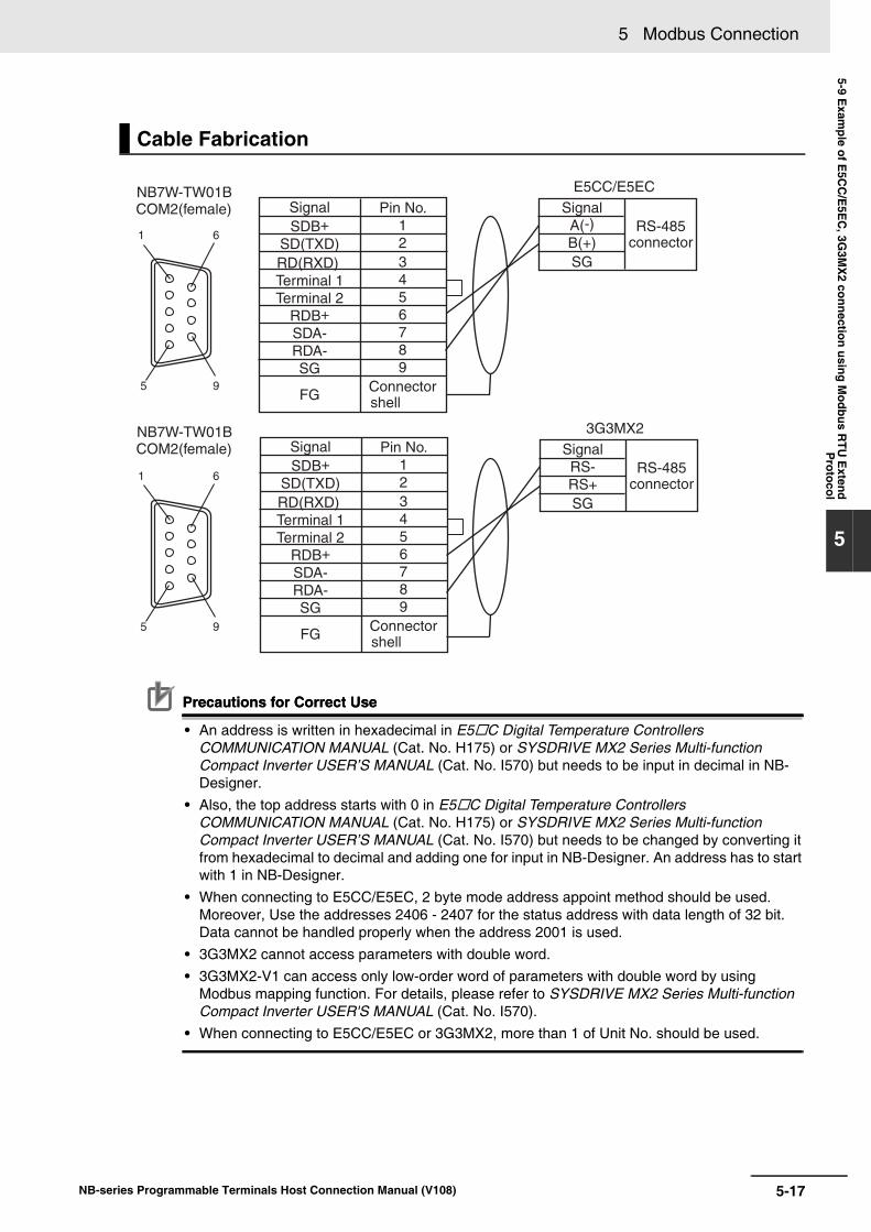
5-17
5 Modbus Connection
NB-series Programmable Terminals Host Connection Manual (V108)
5-9 Exam
ple of E5C
C/E
5EC
, 3G3M
X2 connection using M
odbus RTU
Extend
Protocol
5
Precautions for Correct UsePrecautions for Correct Use
• An address is written in hexadecimal in E5C Digital Temperature Controllers COMMUNICATION MANUAL (Cat. No. H175) or SYSDRIVE MX2 Series Multi-function Compact Inverter USER’S MANUAL (Cat. No. I570) but needs to be input in decimal in NB-Designer.
• Also, the top address starts with 0 in E5C Digital Temperature Controllers COMMUNICATION MANUAL (Cat. No. H175) or SYSDRIVE MX2 Series Multi-function Compact Inverter USER’S MANUAL (Cat. No. I570) but needs to be changed by converting it from hexadecimal to decimal and adding one for input in NB-Designer. An address has to start with 1 in NB-Designer.
• When connecting to E5CC/E5EC, 2 byte mode address appoint method should be used. Moreover, Use the addresses 2406 - 2407 for the status address with data length of 32 bit. Data cannot be handled properly when the address 2001 is used.
• 3G3MX2 cannot access parameters with double word. • 3G3MX2-V1 can access only low-order word of parameters with double word by using
Modbus mapping function. For details, please refer to SYSDRIVE MX2 Series Multi-function Compact Inverter USER'S MANUAL (Cat. No. I570).
• When connecting to E5CC/E5EC or 3G3MX2, more than 1 of Unit No. should be used.
Cable Fabrication
1 6
95
1 6
95
NB7W-TW01BCOM2(female)
NB7W-TW01BCOM2(female)
SignalSDB+
SD(TXD)RD(RXD)Terminal 1Terminal 2
RDB+SDA-RDA-SG
FG
Pin No.123456789
Connectorshell
SignalSDB+
SD(TXD)RD(RXD)Terminal 1Terminal 2
RDB+SDA-RDA-SG
FG
Pin No.123456789
Connectorshell
E5CC/E5EC
RS-485connector
SignalA(-)B(+)SG
3G3MX2
RS-485connector
SignalRS-RS+SG

5 Modbus Connection
5-18 NB-series Programmable Terminals Host Connection Manual (V108)
5-10 Example of Power PMAC Motion Controller using Modbus TCP Slave Protocol
The NB communicates with the Power PMAC using the Ethernet communication port via the Modbus TCP Slave protocol with the PT designated as a master unit. Therefore, the communication settings between the NB and the Power PMAC must be consistent. This section describes an example of the settings.
System ConfigurationFollowing is an example of configuration and settings when Model NB7W-TW01B is used:
PT Settings
Perform the NB communication settings as described below:

5-19
5 Modbus Connection
NB-series Programmable Terminals Host Connection Manual (V108)
5-10 Exam
ple of Pow
er PM
AC
Motion C
ontroller using Modbus TC
P S
laveP
rotocol
5
Power PMAC Settings
Perform the Power PMAC settings as described below:
In addition, add the following item to the "global definitions.pmh" file on the Power PMAC IDE tool tomake the Power PMAC operate as the Modbus TCP slave unit.
Sys.ModbusServerEnable = 1

5 Modbus Connection
5-20 NB-series Programmable Terminals Host Connection Manual (V108)
Address MappingThe data on the Power PMAC are managed as variables. By enabling the Modbus TCP slave func-tion on the Power PMAC side, the Modbus addresses are automatically linked with those of the vari-ables on the Power PMAC. The following table shows the address correspondence between PMACand Modbus.
Note that all the Power PMAC variables are handled in the 32-bit floating-point representation, andthat NB therefore must read/write data in units of 32 bits. Beware that the functions that cannot han-dle the 32-bit floating-point format are not available.
In addition, the Power PMAC, by default, sends data with the 16 high bits and the 16 low bitsswitched. Thus, for the Modbus address, you must use the DINV area.
Precautions for Correct UsePrecautions for Correct Use
To make communication efficient, the NB exchanges as a batch the data of the length accordingto the values specified in "Max size of word block package". For example, when addresses 4X-DINV 00001, 4X-DINV 00008, and 4X-DINV 00016 exist on the screen while this is set to 16, theNB obtains 4X-DINV 00001 through 4X-DINV 00016 as a batch.
However, the Power PMAC does not support communication of the data that extend across dif-ferent variables. Therefore, be careful of the following points.
When assigning multiple variables on a single screen, make sure that the range specified by“Max size of word block package” does not include more than one address.
Example of correct settings:
Address set for Object 1: I6143(4X-DINV 16384)
Address set for Object 2: M200(4X-DINV 16786)
Example of erroneous settings:
Address set for Object 1: I6143(4X-DINV 16384)
Address set for Object 2: M2(4X-DINV 16390)
To freely set addresses, set "Max size of word block package" to "2". Note, however, that whenyou perform the above setting, the amount of communication becomes large, which will affectperformance. Confirm the performance before moving on to actual operations.
PMAC variables Address range Modbus addresses Address range
I variable I0-6143 4X-DINV 4098-16384
M variable M0-8191 4X-DINV 16386-32768
P variable P0-8191 4X-DINV 32770-49152
Q variable &0 Q0-1023 4X-DINV 49154-51200
6-1NB-series Programmable Terminals Host Connection Manual (V108)
6
This section describes the connection to Delta PLCs
6-1 Serial Port Communication . . . . . . . . . . . . . . . . . . . . . . . . . . . . . . . . . . . . . . 6-2
6-2 Communication Parameters and Cable Fabrication . . . . . . . . . . . . . . . . . . 6-3
6-3 Communication Parameter Setting . . . . . . . . . . . . . . . . . . . . . . . . . . . . . . . 6-4
6-4 Supported Registers . . . . . . . . . . . . . . . . . . . . . . . . . . . . . . . . . . . . . . . . . . . 6-6
6-5 Cable Fabrication . . . . . . . . . . . . . . . . . . . . . . . . . . . . . . . . . . . . . . . . . . . . . . 6-7
Connecting to Delta PLCs

6 Connecting to Delta PLCs
6-2 NB-series Programmable Terminals Host Connection Manual (V108)
6-1 Serial Port Communication
Series CPU Link Module Driver
DVP DVP-XXES/EX/SSDVP-XXSA/SX/SCDVP-XXEH/EH2/SV
RS232 on the CPU unit Delta DVP
RS485 on port

6-3
6 Connecting to Delta PLCs
NB-series Programmable Terminals Host Connection Manual (V108)
6-2 Com
munication P
arameters and C
able Fabrication
6
6-2 Communication Parameters and Cable Fabrication
Series CPU Link Module COMM Type Parameter Cable
DVP DVP-XXES/EX/SSDVP-XXSA/SX/SCDVP-XXEH/EH2/SV
RS232 on the CPU unit
RS232 Refer to Section 6-3
Self-made cable required
RS485 on port RS485
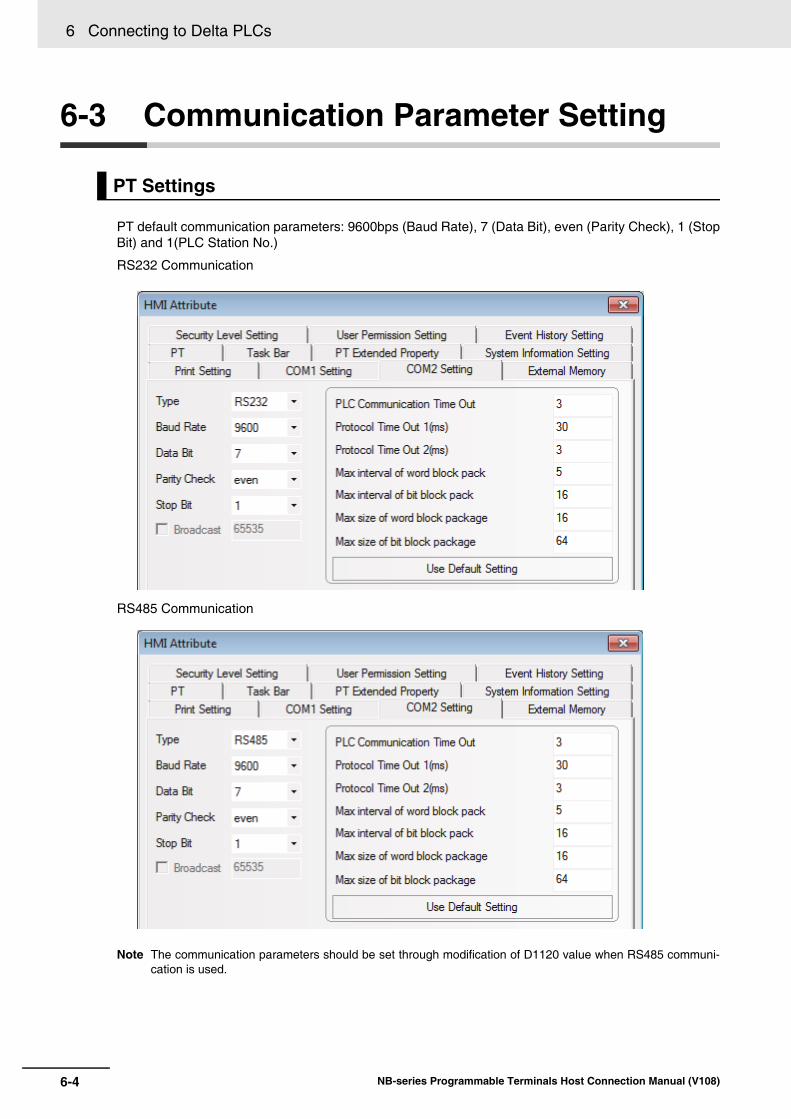
6 Connecting to Delta PLCs
6-4 NB-series Programmable Terminals Host Connection Manual (V108)
6-3 Communication Parameter Setting
PT default communication parameters: 9600bps (Baud Rate), 7 (Data Bit), even (Parity Check), 1 (StopBit) and 1(PLC Station No.)
RS232 Communication
RS485 Communication
Note The communication parameters should be set through modification of D1120 value when RS485 communi-cation is used.
PT Settings

6-5
6 Connecting to Delta PLCs
NB-series Programmable Terminals Host Connection Manual (V108)
6-3 Com
munication P
arameter S
etting
6
1 You can check the baud rates equivalent to the value of D1120 in the dialog box, “RS-485 Protocol Setting (D1120)” after selecting [Help] menu in the Wpl207 software, and [Auxiliary Editing] in the “Help” in the Wpl207 software.
2 Monitor and modify the value of D1120 after PLC is connected to Wpl207.For example: If the communication parameters are 110bps (Baud Rate), 7 (Data Length), None(Parity) and 1 bit (Stop Bits), then D1120=H0010 (Protocol Setting).
PLC Settings
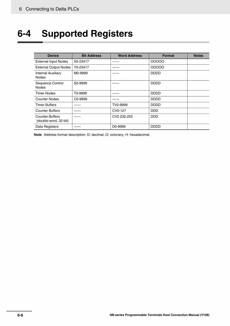
6 Connecting to Delta PLCs
6-6 NB-series Programmable Terminals Host Connection Manual (V108)
6-4 Supported Registers
Note Address format description: D: decimal, O: octonary, H: hexadecimal.
Device Bit Address Word Address Format Notes
External Input Nodes X0-23417 ------ OOOOO
External Output Nodes Y0-23417 ------ OOOOO
Internal Auxiliary Nodes
M0-9999 ------ DDDD
Sequence Control Nodes
S0-9999 ------ DDDD
Timer Nodes T0-9999 ------ DDDD
Counter Nodes C0-9999 ------ DDDD
Timer Buffers ------ TV0-9999 DDDD
Counter Buffers ------ CV0-127 DDD
Counter Buffers (double-word, 32-bit)
------ CV2 232-255 DDD
Data Registers ------ D0-9999 DDDD

6-7
6 Connecting to Delta PLCs
NB-series Programmable Terminals Host Connection Manual (V108)
6-5 Cable Fabrication
6
6-5 Cable Fabrication
RS232 Communication Cable
RS485 Communication Cable
PT (COM1/COM2)Pin No.
239
SignalSDRDSG
D-Sub 9Pin
(Female)
PLCPin No.
458
SignalRXDTXDGND
8Pin Mini Din
(Male)
PT (COM2)Pin No.
689
SignalRDB+RDA-SG
D-Sub 9Pin
(Female)
PLCSignal
SDB+/RDB+SDA-/RDA-
SG
RS-485connector
45
Terminal R1 Terminal R2

6 Connecting to Delta PLCs
6-8 NB-series Programmable Terminals Host Connection Manual (V108)
7-1NB-series Programmable Terminals Host Connection Manual (V108)
7
This section describes the connection to LSIS PLCs
7-1 Serial Port Communication . . . . . . . . . . . . . . . . . . . . . . . . . . . . . . . . . . . . . . 7-2
7-2 Communication Parameters and Cable Fabrication . . . . . . . . . . . . . . . . . . 7-3
7-3 Communication Parameter Setting . . . . . . . . . . . . . . . . . . . . . . . . . . . . . . . 7-4
7-4 Supported Registers . . . . . . . . . . . . . . . . . . . . . . . . . . . . . . . . . . . . . . . . . . . 7-9
7-5 Cable Fabrication . . . . . . . . . . . . . . . . . . . . . . . . . . . . . . . . . . . . . . . . . . . . . 7-11
Connecting to LSIS PLCs

7 Connecting to LSIS PLCs
7-2 NB-series Programmable Terminals Host Connection Manual (V108)
7-1 Serial Port Communication
The differences between LS Master-K CPU Direct, LS Master-K Cnet and LS Master-K Modbus RTUprotocols are as shown below:
Series Type CPU Link Module Driver
Master-K K120S K7M-DR10UE Port1 on CPU unit
Port2 on CPU unit
LS Master-K CPU Direct
LS Master-K Cnet
LS Master-K Modbus RTUK7M-DR20U
K7M-DT30U
K7M-DT40U
K7M-DT60U
K200S K3P-07AS RS232 on the CPU unit
XGT XGB XBC-DN64H RS232 on the CPU unit LS XGT CPU Direct
XBC-DR32H Built-in RS-232C/RS-485 LS XGT Cnet
Communication Protocol PLC Settings
Supported Com-munication Meth-
odsMultiple Station No. Supported Baud
Rate (bps)
LS Master-K Cnet Tweak the pin 2 (up) of DIP switch to ON and pin 1 (low) of DIP switch to OFF
RS-232/RS-485 Supported 9600/19200/38400
LS Master-K MODBUS RTU
Tweak the pin 2 (up) of DIP switch to ON and pin 1 (low) of DIP switch to OFF
RS-232/RS-485 Supported 9600/19200/38400
LS Master-K CPU Direct
Pin 1 and pin 2 remain OFF
RS-232 Not supported 38400
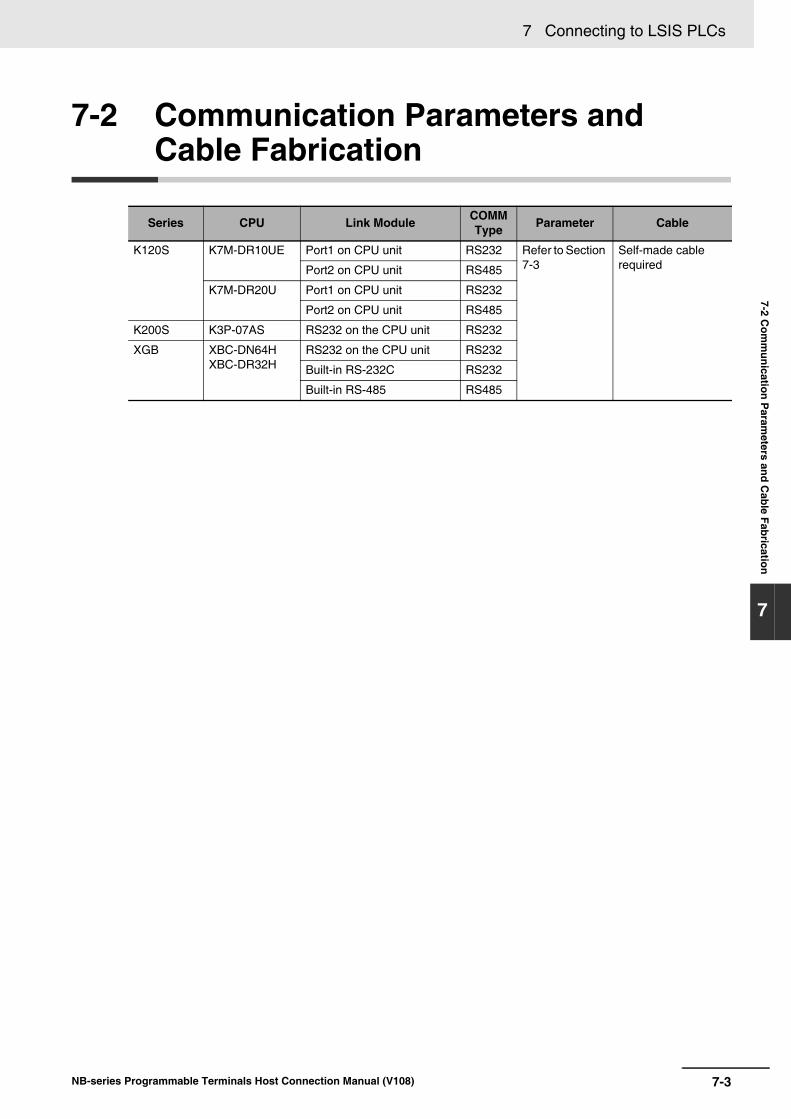
7-3
7 Connecting to LSIS PLCs
NB-series Programmable Terminals Host Connection Manual (V108)
7-2 Com
munication P
arameters and C
able Fabrication
7
7-2 Communication Parameters and Cable Fabrication
Series CPU Link Module COMM Type Parameter Cable
K120S K7M-DR10UE Port1 on CPU unit RS232 Refer to Section 7-3
Self-made cable requiredPort2 on CPU unit RS485
K7M-DR20U Port1 on CPU unit RS232
Port2 on CPU unit RS485
K200S K3P-07AS RS232 on the CPU unit RS232
XGB XBC-DN64HXBC-DR32H
RS232 on the CPU unit RS232
Built-in RS-232C RS232
Built-in RS-485 RS485

7 Connecting to LSIS PLCs
7-4 NB-series Programmable Terminals Host Connection Manual (V108)
7-3 Communication Parameter Setting
When Using LS Master-K Cnet Protocol PT default communication parameters: 38400bps (Baud Rate), 8 (Data Bit), none (Parity Check), 1 (Stop Bit) and 1(PLC Station No.)
RS232 Communication
RS485 Communication
When Using LS Master-K CPU Direct ProtocolPT default communication parameters: 38400bps (Baud Rate), 8 (Data Bit), none (Parity Check), 1 (Stop Bit) and 1 (PLC Station No.)
PT Settings
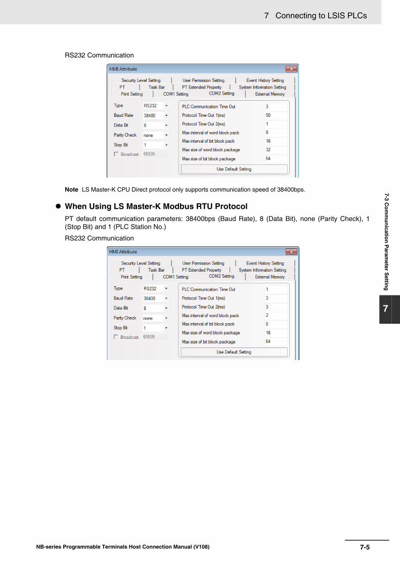
7-5
7 Connecting to LSIS PLCs
NB-series Programmable Terminals Host Connection Manual (V108)
7-3 Com
munication P
arameter S
etting
7
RS232 Communication
Note LS Master-K CPU Direct protocol only supports communication speed of 38400bps.
When Using LS Master-K Modbus RTU Protocol PT default communication parameters: 38400bps (Baud Rate), 8 (Data Bit), none (Parity Check), 1(Stop Bit) and 1 (PLC Station No.)
RS232 Communication

7 Connecting to LSIS PLCs
7-6 NB-series Programmable Terminals Host Connection Manual (V108)
When Using LS XGT CPU Direct Protocol PT default communication parameters: 115200bps (Baud Rate), 8 (Data Bit), none (Parity Check), 1(Stop Bit) and 0 (PLC Station No.)
RS232 Communication
Note LS XGT CPU Direct protocol only supports communication speed of 115200bps and the Multiple Station No.is not supported.
When Using LS XGT Cnet Protocol PT default communication parameters: 9600bps (Baud Rate), 8 (Data Bit), none (Parity Check), 1 (StopBit) and 0 (PLC Station No.)
RS232 Communication
RS485 Communication

7-7
7 Connecting to LSIS PLCs
NB-series Programmable Terminals Host Connection Manual (V108)
7-3 Com
munication P
arameter S
etting
7
When Using LS Master-K Cnet Protocol The software settings are as shown below (Please pay attention to the settings encircled by red line.):
When Using LS Master-K Modbus RTU Protocol The software settings are as shown below (Please pay attention to the settings encircled by red line.):
The “Cannot Change PLC Mode” will appear when [Connect+Write+Run+Monitor Start] is clicked, then manual control is needed and download operation is available only when the RUN light is OFF. After the download operation is completed, the RUN light should maintain ON.
PLC Settings
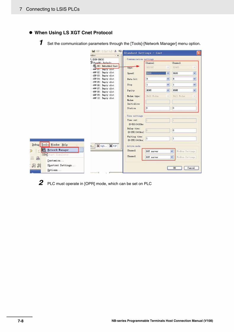
7 Connecting to LSIS PLCs
7-8 NB-series Programmable Terminals Host Connection Manual (V108)
When Using LS XGT Cnet Protocol
1 Set the communication parameters through the [Tools]-[Network Manager] menu option.
2 PLC must operate in [OPR] mode, which can be set on PLC
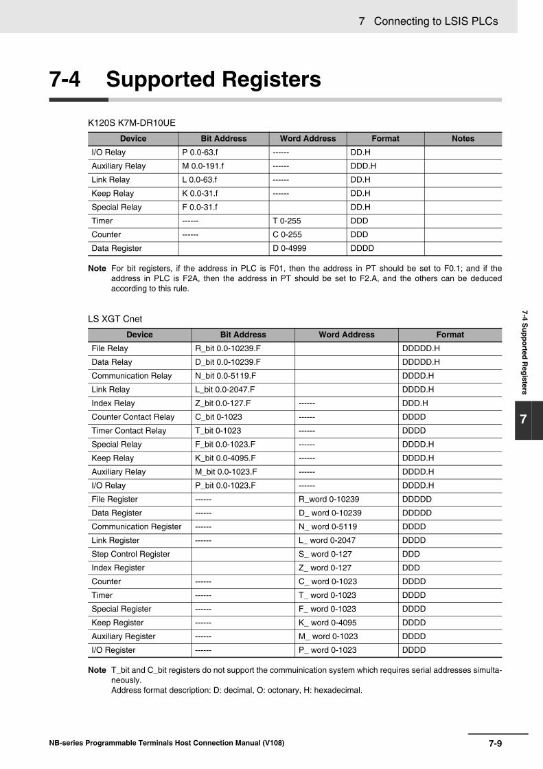
7-9
7 Connecting to LSIS PLCs
NB-series Programmable Terminals Host Connection Manual (V108)
7-4 Supported R
egisters
7
7-4 Supported Registers
K120S K7M-DR10UE
Note For bit registers, if the address in PLC is F01, then the address in PT should be set to F0.1; and if theaddress in PLC is F2A, then the address in PT should be set to F2.A, and the others can be deducedaccording to this rule.
LS XGT Cnet
Note T_bit and C_bit registers do not support the commuinication system which requires serial addresses simulta-neously. Address format description: D: decimal, O: octonary, H: hexadecimal.
Device Bit Address Word Address Format Notes
I/O Relay P 0.0-63.f ------ DD.H
Auxiliary Relay M 0.0-191.f ------ DDD.H
Link Relay L 0.0-63.f ------ DD.H
Keep Relay K 0.0-31.f ------ DD.H
Special Relay F 0.0-31.f DD.H
Timer ------ T 0-255 DDD
Counter ------ C 0-255 DDD
Data Register D 0-4999 DDDD
Device Bit Address Word Address Format
File Relay R_bit 0.0-10239.F DDDDD.H
Data Relay D_bit 0.0-10239.F DDDDD.H
Communication Relay N_bit 0.0-5119.F DDDD.H
Link Relay L_bit 0.0-2047.F DDDD.H
Index Relay Z_bit 0.0-127.F ------ DDD.H
Counter Contact Relay C_bit 0-1023 ------ DDDD
Timer Contact Relay T_bit 0-1023 ------ DDDD
Special Relay F_bit 0.0-1023.F ------ DDDD.H
Keep Relay K_bit 0.0-4095.F ------ DDDD.H
Auxiliary Relay M_bit 0.0-1023.F ------ DDDD.H
I/O Relay P_bit 0.0-1023.F ------ DDDD.H
File Register ------ R_word 0-10239 DDDDD
Data Register ------ D_ word 0-10239 DDDDD
Communication Register ------ N_ word 0-5119 DDDD
Link Register ------ L_ word 0-2047 DDDD
Step Control Register S_ word 0-127 DDD
Index Register Z_ word 0-127 DDD
Counter ------ C_ word 0-1023 DDDD
Timer ------ T_ word 0-1023 DDDD
Special Register ------ F_ word 0-1023 DDDD
Keep Register ------ K_ word 0-4095 DDDD
Auxiliary Register ------ M_ word 0-1023 DDDD
I/O Register ------ P_ word 0-1023 DDDD
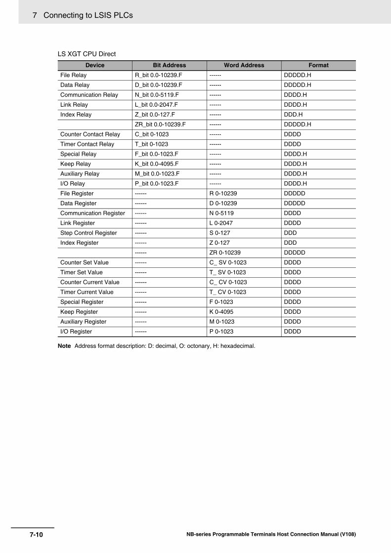
7 Connecting to LSIS PLCs
7-10 NB-series Programmable Terminals Host Connection Manual (V108)
LS XGT CPU Direct
Note Address format description: D: decimal, O: octonary, H: hexadecimal.
Device Bit Address Word Address Format
File Relay R_bit 0.0-10239.F ------ DDDDD.H
Data Relay D_bit 0.0-10239.F ------ DDDDD.H
Communication Relay N_bit 0.0-5119.F ------ DDDD.H
Link Relay L_bit 0.0-2047.F ------ DDDD.H
Index Relay Z_bit 0.0-127.F ------ DDD.H
ZR_bit 0.0-10239.F ------ DDDDD.H
Counter Contact Relay C_bit 0-1023 ------ DDDD
Timer Contact Relay T_bit 0-1023 ------ DDDD
Special Relay F_bit 0.0-1023.F ------ DDDD.H
Keep Relay K_bit 0.0-4095.F ------ DDDD.H
Auxiliary Relay M_bit 0.0-1023.F ------ DDDD.H
I/O Relay P_bit 0.0-1023.F ------ DDDD.H
File Register ------ R 0-10239 DDDDD
Data Register ------ D 0-10239 DDDDD
Communication Register ------ N 0-5119 DDDD
Link Register ------ L 0-2047 DDDD
Step Control Register ------ S 0-127 DDD
Index Register ------ Z 0-127 DDD
------ ZR 0-10239 DDDDD
Counter Set Value ------ C_ SV 0-1023 DDDD
Timer Set Value ------ T_ SV 0-1023 DDDD
Counter Current Value ------ C_ CV 0-1023 DDDD
Timer Current Value ------ T_ CV 0-1023 DDDD
Special Register ------ F 0-1023 DDDD
Keep Register ------ K 0-4095 DDDD
Auxiliary Register ------ M 0-1023 DDDD
I/O Register ------ P 0-1023 DDDD

7-11
7 Connecting to LSIS PLCs
NB-series Programmable Terminals Host Connection Manual (V108)
7-5 Cable Fabrication
7
7-5 Cable Fabrication
RS232 Communication Cable
RS485 Communication Cable
RS232 Communication Cable
RS232 Communication Cable
When Using LS Master-K Cnet/LS Master-K Modbus RTU Protocol
When Using LS Master-K CPU Direct Protocol
When Using LS XGT CPU Direct Protocol
PT (COM1/COM2)Pin No.
239
SignalSDRDSG
D-Sub 9Pin
(Female)
PLCPin No.
475
SignalRXTXSG
D-Sub 9Pin
(Female)
PT (COM2)Pin No.
689
SignalRDB+RDA-SG
D-Sub 9Pin
(Female)
PLCSignal
SDB+/RDB+SDA-/RDA-
SG
RS-485connector
4Terminal R15Terminal R2
PT (COM1/COM2)Pin No.
239
SignalSDRDSG
D-Sub 9Pin
(Female)
PLCPin No.
235
SignalRXTX
GND
D-Sub 9Pin
(Female)
PT (COM1/COM2)Pin No.
239
SignalSDRDSG
D-Sub 9Pin
(Female)
PLCPin No.
263
SignalRXTX
GND
6Pin Mini Din
(Female)
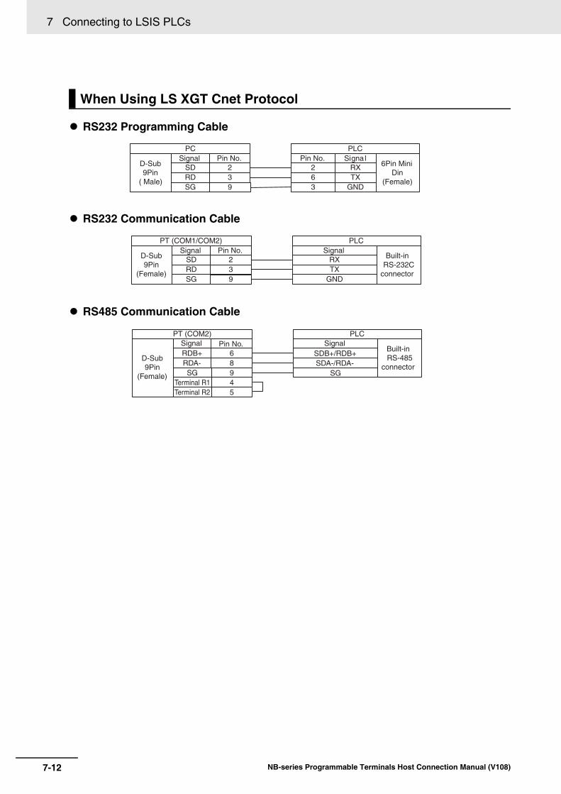
7 Connecting to LSIS PLCs
7-12 NB-series Programmable Terminals Host Connection Manual (V108)
RS232 Programming Cable
RS232 Communication Cable
RS485 Communication Cable
When Using LS XGT Cnet Protocol
PC Pin No.
239
SignalSDRDSG
D-Sub 9Pin
( Male)
PLCPin No.
263
SignalRXTX
GND
6Pin Mini Din
(Female)
PT (COM1/COM2)Pin No.
239
SignalSDRDSG
D-Sub 9Pin
(Female)
PLCSignal
RXTX
GND
Built-in RS-232C
connector
PT (COM2)Pin No.
689
SignalRDB+RDA-SG
D-Sub 9Pin
(Female)
PLCSignal
SDB+/RDB+SDA-/RDA-
SG
Built-in RS-485
connector
4Terminal R15Terminal R2

8-1NB-series Programmable Terminals Host Connection Manual (V108)
8
This section describes the connection to Panasonic Industrial Devices SUNX PLCs.
8-1 Serial Port Communication . . . . . . . . . . . . . . . . . . . . . . . . . . . . . . . . . . . . . . 8-2
8-2 Communication Parameters and Cable Fabrication . . . . . . . . . . . . . . . . . . 8-3
8-3 Communication Parameter Setting . . . . . . . . . . . . . . . . . . . . . . . . . . . . . . . 8-4
8-4 Supported Registers . . . . . . . . . . . . . . . . . . . . . . . . . . . . . . . . . . . . . . . . . . . 8-5
8-5 Cable Fabrication . . . . . . . . . . . . . . . . . . . . . . . . . . . . . . . . . . . . . . . . . . . . . . 8-6
Connecting to Panasonic Industrial Devices SUNX PLCs
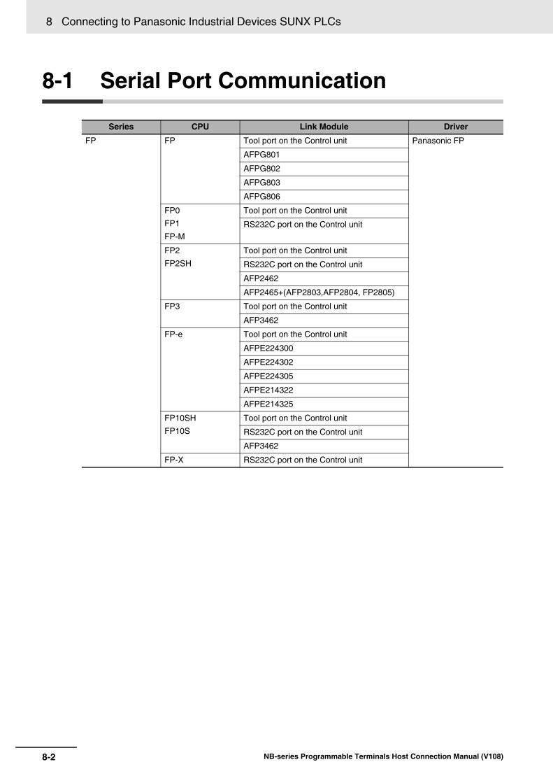
8 Connecting to Panasonic Industrial Devices SUNX PLCs
8-2 NB-series Programmable Terminals Host Connection Manual (V108)
8-1 Serial Port Communication
Series CPU Link Module Driver
FP FP Tool port on the Control unit Panasonic FP
AFPG801
AFPG802
AFPG803
AFPG806
FP0
FP1
FP-M
Tool port on the Control unit
RS232C port on the Control unit
FP2
FP2SH
Tool port on the Control unit
RS232C port on the Control unit
AFP2462
AFP2465+(AFP2803,AFP2804, FP2805)
FP3 Tool port on the Control unit
AFP3462
FP-e Tool port on the Control unit
AFPE224300
AFPE224302
AFPE224305
AFPE214322
AFPE214325
FP10SH
FP10S
Tool port on the Control unit
RS232C port on the Control unit
AFP3462
FP-X RS232C port on the Control unit

8-3
8 Connecting to Panasonic Industrial Devices SUNX PLCs
NB-series Programmable Terminals Host Connection Manual (V108)
8-2 Com
munication P
arameters and C
able Fabrication
8
8-2 Communication Parameters and Cable Fabrication
Note 1 Only FP0 (C10CRM/C10CRS/C14CRM/C14CRS/C16T/C16CP/C32CT/C32CP) has RS232C communi-cation port.
2 Only FP1 (C24/C40/C56/C72) has RS232C communication port.
3 Only FP1 (C20R/C20T/C32T) has RS232C communication port.
4 AFP245 is the multi-communication unit for FP2/FP2SH. AFP2803, AFP2804 and AFP2805 are the com-munication modules connecting to AFP2465.
Series CPU Link Module COMM Type Parameter Cable
FP FP Tool port on the Control unit RS232C Refer to
Section 8-3
Self-made cable requiredAFPG801
AFPG802
AFPG806
AFPG803 RS485
AFPG806
FP0 Tool port on the Control unit RS232C
RS232C port on the Control unit
FP1
FP-M
Tool port on the Control unit RS232C
RS232C port on the Control unit
FP2
FP2SH
Tool port on the Control unit RS232C
RS232C port on the Control unit
AFP2462
AFP2465 AFP2803
AFP2804 RS422
AFP2805 RS485
FP3 Tool port on the Control unit RS232C
AFP3462
AFP3463 RS422
FP-e Tool port on the Control unit RS232C
AFPE224300 RS232C
AFPE214325
AFPE224305
AFPE224302 RS485
AFPE214322
FP10SH
FP10S
Tool port on the Control unit RS232C
RS232C port on the Control unit
AFP3462
FP-X RS232C port on the Control unit RS232C

8 Connecting to Panasonic Industrial Devices SUNX PLCs
8-4 NB-series Programmable Terminals Host Connection Manual (V108)
8-3 Communication Parameter Setting
PT default communication parameters: 9600bps (Baud Rate), 8 (Data Bit), odd (Parity Check), 1 (Stop Bit) and 1 (PLC Station No.) RS232 Communication
RS485 Communication
RS422 Communication
Please refer to relevant instruction manual of communication device on parameter settings.
PT Settings
PLC Settings
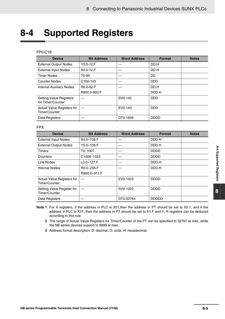
8-5
8 Connecting to Panasonic Industrial Devices SUNX PLCs
NB-series Programmable Terminals Host Connection Manual (V108)
8-4 Supported R
egisters
8
8-4 Supported Registers
FP0-C16
FPX
Note 1 For X registers, if the address in PLC is X01,then the address in PT should be set to X0.1; and if theaddress in PLC is X1F, then the address in PT should be set to X1.F and Y, R registers can be deducedaccording to this rule.
2 The range of Actual Value Registers for Timer/Counter of the PT can be specified to 32767 at max, whilethe NB series devices support to 9999 at max.
3 Address format description: D: decimal, O: octal, H: hexadecimal.
Device Bit Address Word Address Format Notes
External Output Nodes Y0.0-12.F --- DD.H
External Input Nodes X0.0-12.F --- DD.H
Timer Nodes T0-99 --- DD
Counter Nodes C100-143 --- DDD
Internal Auxiliary Nodes R0.0-62.F
R900.0-903.F
--- DD.H
DDD.H
Setting Value Registers for Timer/Counter
--- SV0-143 DDD
Actual Value Registers for Timer/Counter
--- EV0-143 DDD
Data Registers --- DT0-1659 DDDD
Device Bit Address Word Address Format Notes
External Input Nodes X0.0~109.F --- DDD.H
External Output Nodes Y0.0~109.F --- DDD.H
Timers T0~1007 --- DDDD
Counters C1008~1023 --- DDDD
Link Nodes L0.0~127.F --- DDD.H
Internal Nodes R0.0~255.F
R900.0~911.F
--- DDD.H
Actual Value Registers for Timer/Counter
--- EV0-1023 DDDD
Setting Value Register for Timer/Counter
--- SV0-1023 DDDD
Data Registers --- DT0-32764 DDDDD

8 Connecting to Panasonic Industrial Devices SUNX PLCs
8-6 NB-series Programmable Terminals Host Connection Manual (V108)
8-5 Cable Fabrication
RS232 Communication Cable• Tool port
• CPU port
• COM port
RS485 Communication Cable
PT (COM1/COM2)Pin No.
239
SignalSDRDSG
D-Sub 9Pin
(Female)
PLCPin No.
321
SignalRXDTXDSG
5Pin Mini Din
(Female)
PT (COM1/COM2)
Pin No.239
SignalSDRDSG
D-Sub 9Pin
(Female)
PLC FP0 CPU
SignalRSG
RS-232communication
port
PT (COM1/COM2)Pin No.
239
SignalSDRDSG
D-Sub 9Pin
(Female)
PLCPin No.
327
SignalRXDTXDGND D-Sub
9Pin(Female)4
589
RTSCTSCDER
PT (COM2)Pin No.
68
SignalRDB+RDA-
D-Sub 9Pin
(Female)
PLCSignal
SDB+/RDB+SDA-/RDA-
RS-485connector
4Terminal R15Terminal R2

8-7
8 Connecting to Panasonic Industrial Devices SUNX PLCs
NB-series Programmable Terminals Host Connection Manual (V108)
8-5 Cable Fabrication
8
RS422 Communication Cable• FP3 RS422 programming port
• RS422 communication port for other modules
PT (COM2)Pin No.
167
SignalSDB+RDB+SDA-
D-Sub 9Pin
(Female)
PLCPin No.
3210
SignalRXDBTXDBRXDA D-Sub
15Pin(Female)
89
RDA-SG
97
TXDAGND
45
RTA+CTS+
1112
RTS-CTS-
4Terminal R15Terminal R2
PT (COM2)Pin No.
167
SignalSDB+RDB+SDA-
D-Sub 9Pin
(Female)
PLC RS-422 connectorPin No.
325
SignalRD+SD+RD-
D-Sub9Pin
(Female)8RDA- 4 SD-4Terminal R15Terminal R2

8 Connecting to Panasonic Industrial Devices SUNX PLCs
8-8 NB-series Programmable Terminals Host Connection Manual (V108)

9-1NB-series Programmable Terminals Host Connection Manual (V108)
9
This section describes the connection to Allen-Bradley PLC.
9-1 Serial Port Communication and Ethernet . . . . . . . . . . . . . . . . . . . . . . . . . . 9-29-1-1 Serial Port . . . . . . . . . . . . . . . . . . . . . . . . . . . . . . . . . . . . . . . . . . . . . . . . . . . . 9-29-1-2 Ethernet . . . . . . . . . . . . . . . . . . . . . . . . . . . . . . . . . . . . . . . . . . . . . . . . . . . . . . 9-3
9-2 Communication Parameters and Cable Fabrication . . . . . . . . . . . . . . . . . . 9-49-2-1 Serial Port . . . . . . . . . . . . . . . . . . . . . . . . . . . . . . . . . . . . . . . . . . . . . . . . . . . . 9-49-2-2 Ethernet . . . . . . . . . . . . . . . . . . . . . . . . . . . . . . . . . . . . . . . . . . . . . . . . . . . . . . 9-4
9-3 Communication Parameter Setting . . . . . . . . . . . . . . . . . . . . . . . . . . . . . . . 9-59-3-1 When Using AB SLC500/MicroLogix Series (DF1) Protocol . . . . . . . . . . . . . . 9-59-3-2 When Using AB CompactLogix/ControlLogix Series (DF1) Protocol . . . . . . . . 9-79-3-3 AB MicroLogix Series Ethernet(TCP Slave) . . . . . . . . . . . . . . . . . . . . . . . . . 9-11
9-4 Supported Registers . . . . . . . . . . . . . . . . . . . . . . . . . . . . . . . . . . . . . . . . . . 9-14
9-5 Cable Fabrication . . . . . . . . . . . . . . . . . . . . . . . . . . . . . . . . . . . . . . . . . . . . . 9-16
Connecting to Allen-Bradley (Rockwell) PLC

9 Connecting to Allen-Bradley (Rockwell) PLC
9-2 NB-series Programmable Terminals Host Connection Manual (V108)
9-1 Serial Port Communication and Ethernet
9-1-1 Serial Port
Series CPU Link Module Driver
MicroLogix MicroLogix 1500
(1764-LRP)
Channel 1 AB SLC500/MicroLogix Series (DF1)
MicroLogix 1000MicroLogix 1200MicroLogix 1500(1764-LSP, 1764-LRP)
Channel 0
AIC + Advanced Interface Converter1761-NET-AIC
MicroLogix 1400(1766-L32BWAA)
Channel 0
Channel 2
SLC500 SLC 5/03SLC 5/04SLC 5/05
Channel 0
1770-KF3
2760-RB
1775-KA
5130-RM
1771-KGM
CompactLogix 1769-L201769-L301769-L311769-L32E1769-L35E
Channel 0
Channel 1
AB CompactLogix/ControlLogix Series (DF1)
ControlLogix 1756-L61
1756-L63
CPU Direct
9-3
9 Connecting to Allen-Bradley (Rockwell) PLC
NB-series Programmable Terminals Host Connection Manual (V108)
9-1 Serial P
ort Com
munication and E
thernet
9
9-1-2 Ethernet
9-1-2 Ethernet
Series CPU Link Module Driver
MicroLogix MicroLogix 1100
MicroLogix 1400
Ethernet port on CPU Unit AB MicroLogix Series Ethernet (TCP Slave)
MicroLogix 1000
MicroLogix 1200
MicroLogix 1400
MicroLogix 1500
Communication Module 1761-NET-ENI

9 Connecting to Allen-Bradley (Rockwell) PLC
9-4 NB-series Programmable Terminals Host Connection Manual (V108)
9-2 Communication Parameters and Cable Fabrication
9-2-1 Serial Port
Series CPU Link Module COMM Type Parameter Cable
MicroLogix MicroLogix 1500 (1764-LRP)
Channel 1 RS232C Refer to Section 9-3 Self-made cable required
MicroLogix 1000MicroLogix 1200MicroLogix 1500(1764-LSP, 1764-LRP)
Channel 0
AIC +AdvancedInterface Converter1761-NET-AIC
MicroLogix 1400(1766-L32BWAA)
Channel 0
Channel 2
SLC500 SLC 5/03
SLC 5/04
SLC 5/05
Channel 0 RS232C
1770-KF32760-RB1775-KA5130-RM
1771-KGM
CompactLogix 1769-L201769-L301769-L311769-L32E1769-L35E
Channel 0 RS232C
Channel 1
ControlLogix 1756-L61 CPU Direct RS232C
9-2-2 Ethernet
Series CPU Link Module COMM Type Parameter Cable
MicroLogix MicroLogix 1100
MicroLogix 1400
Ethernet port on CPU Unit
- Refer to Section 9-3 Network Cable
MicroLogix 1000
MicroLogix 1200
MicroLogix 1400
MicroLogix 1500
Communication Module 1761-NET-ENI
-
9-5
9 Connecting to Allen-Bradley (Rockwell) PLC
NB-series Programmable Terminals Host Connection Manual (V108)
9-3 Com
munication P
arameter S
etting
9
9-3-1 When U
sing AB
SLC
500/MicroLogix S
eries (DF1)
Protocol
9-3 Communication Parameter Setting
MicroLogix default communication parameters: 19200 (Baud Rate), 8 (Data Bit), none (Parity), 1 (Stop Bit) and 0 (Station No.)
SLC500 default communication parameters: 9600 (Baud Rate), 8 (Data Bit), none (Parity), 1 (Stop Bit) and 0 (Station No.)
9-3-1 When Using AB SLC500/MicroLogix Series (DF1) Protocol
PT Settings

9 Connecting to Allen-Bradley (Rockwell) PLC
9-6 NB-series Programmable Terminals Host Connection Manual (V108)
• RSLogix500 software setting (Take MicroLogix 1500 as example)
Select the “DF1 Full Duplex” for Driver option and “CRC” for the [Error Detection] option in the ChannelConfiguration dialog box of the software.
And the register setting is also available.
Rules of register setting:
(1) The file number should be unique. This number is set when the register is created, and after the creation, the file number will be fixed and therefore cannot be modified.
(2) The range of PLC addresses should be greater than the settings of the PT.
(3) The PLC has a limited memory capacity. During downloading, if a message “Program has errors, cannot download” pops up, it indicates the occurrence of an over-range caused by too many addresses allocation.
(4) T and C areas do not support the communication system which requires serial addresses simultaneously.
PLC Settings

9-7
9 Connecting to Allen-Bradley (Rockwell) PLC
NB-series Programmable Terminals Host Connection Manual (V108)
9-3 Com
munication P
arameter S
etting
9
9-3-2 When U
sing AB
Com
pactLogix/ControlLogix S
eries (D
F1) P
rotocol
CompactLogix/ControlLogix default communication parameters: 19200 (Baud Rate), 8 (Data Bit), none (Parity), 1 (Stop Bit) and 0 (Station No.)
9-3-2 When Using AB CompactLogix/ControlLogix Series (DF1) Protocol
PT Settings

9 Connecting to Allen-Bradley (Rockwell) PLC
9-8 NB-series Programmable Terminals Host Connection Manual (V108)
• RSLogix5000 Software Settings
Note “DF1 Point to Point” is selected as Protocol; “CRC” is selected as Error Detection and “Enable Duplicate Detection” is not checked.
1 Set the parameters of the communications in [Controller Properties] dialog box.
2 Define the tag and set the data types, then select “Controller Tags” and right-click the “New Tag” option in the dropdown list to create a new tag.
Note 1 The internal registers of the controller to be accessed by the PT needs to be pre-defined in theRSLogix5000 software.
2 Controller Tags apply to all the routines in the controller. For the control, these tags are global, sothey need to be created in “Controller Tags”.
3 Make the Name correspond to the File Number, and then select “Map PLC/SLC Messages” in the dropdown list after “Logic” being selected.
PLC Settings

9-9
9 Connecting to Allen-Bradley (Rockwell) PLC
NB-series Programmable Terminals Host Connection Manual (V108)
9-3 Com
munication P
arameter S
etting
9
9-3-2 When U
sing AB
Com
pactLogix/ControlLogix S
eries (D
F1) P
rotocol
Note The software must be changed to “Offline” status.
• Setting Example
Create a new tag with Name of a and Data Type of INT.
Note 1 When selecting the Data Type, note that the CompactLogix/ControlLogix protocol supports only 3 Data Types such as INT, BOOL, and REAL.
2 The protocol does not support multidimentional array. Only the range of Dim0 can be defined.
3 The range of file number supported by each Data Type is 0 to 253 for INT, 0 to 253 for REAL, and 0 to 999 for BOOL.
Continue to create 2 tags: one with Name of b and Data Type of REAL and the other with name of c and Data Type of BOOL, as shown below:
Note The address range of BOOL variable is defined to 1024 in the PLC, however, the accessible address range is to 999 at max.
9 Connecting to Allen-Bradley (Rockwell) PLC
9-10 NB-series Programmable Terminals Host Connection Manual (V108)
After defining the tags, you also need to make the mapping between the Name and the File Number.
Note 1 The file number should be unique, i.e., the same file number cannot be mapped on the different file names.
2 The file number available to be supported ranges from 0 to 254.
The mapping of the above-mentioned items with NB-Designer addresses is shown as the follow-ing table.
Name Data Type Support Range File Number NB-Designer Address
a INT[255] 0~254 0 INT 000000~000254
s REAL[255] 0~254 1 REAL 001000~001254
b BOOL[1024] 0~999 254 B_BOOL 254000~254999

9-11
9 Connecting to Allen-Bradley (Rockwell) PLC
NB-series Programmable Terminals Host Connection Manual (V108)
9-3 Com
munication P
arameter S
etting
9
9-3-3 AB
MicroLogix S
eries Ethernet(TC
P S
lave)
The Network Settings of PT are as shown below.
9-3-3 AB MicroLogix Series Ethernet(TCP Slave)
PT Settings

9 Connecting to Allen-Bradley (Rockwell) PLC
9-12 NB-series Programmable Terminals Host Connection Manual (V108)
The PLC Settings when using Communication Protocol AB MicroLogix Series Ethernet (TCP Slave) are as shown below.
Using Ethernet port on CPU Unit
1 Start-up RSLogix 500 and double-click [Channel Configuration].
2 Select the tab of a channel to which Ethernet port is allocated.
Set the IP Address to the same address as the PT settings.
PLC Settings
9-13
9 Connecting to Allen-Bradley (Rockwell) PLC
NB-series Programmable Terminals Host Connection Manual (V108)
9-3 Com
munication P
arameter S
etting
9
9-3-3 AB
MicroLogix S
eries Ethernet(TC
P S
lave)
Using the Communication Module
1 Start-up ENI/ENIW Utility.
Set the IP Address to the same parameters as the PT settings.
2 Click ENI ROM to save the settings.

9 Connecting to Allen-Bradley (Rockwell) PLC
9-14 NB-series Programmable Terminals Host Connection Manual (V108)
9-4 Supported Registers
Additional Information
FFF refers to the File Number and DDD refers to the Variable No. Address.
AB SLC500/MicroLogix Series (DF1) Driver
Note 1 The format of I/O address for bit register is “I/O e.s/b”, where, “e” is the slot number, “s” is the pixel number,and “b” is the bit number. If the address in PLC is O0 0.0/11, then the address in PT should be set to “O00.11”; and if the address in PLC is O0 0.1/8, then the address in PT should be set to “O0 1.8”. When AB withthe different CPU types uses the I/O modules, the addresses of I point and O point in PT are arranged con-secutively. Take Micrologix1400 with output module 1762-OW16 as example, the address correspondingto O0 1.0/3 in PT is O0 6.3.
2 When the address is less than three digits, it should be filled with 0 to be three digits.Example: When 113 refer to File number 113 and 10.12 refers to Address 10.12, specify to 113010.12
Device Bit Address Word Address Format Notes
Internal Auxiliary Nodes B3: 0.0~255.15 ------ DDD.DD
Internal Auxiliary Nodes B10: 0.0~255.15 ------ DDD.DD
Internal Auxiliary Nodes B11: 0.0~255.15 ------ DDD.DD
Internal Auxiliary Nodes B12: 0.0~255.15 ------ DDD.DD
Internal Auxiliary Nodes B13: 0.0~255.15 ------ DDD.DD
Internal Auxiliary Nodes Bf:n 0.0~255255.15 ------ FFFDDD.DD *2
External Input Nodes I1: 0.0~255.15 ------ DDD.DD
External Output Nodes O0: 0.0~255.15 ------ DDD.DD
Data Registers ------ N7: 0~255 DDD
Data Registers ------ N10: 0~255 DDD
Data Registers ------ N11: 0~255 DDD
Data Registers ------ N12: 0~255 DDD
Data Registers ------ N13: 0~255 DDD
Data Registers ------ N14: 0~255 DDD
Data Registers ------ N15: 0~255 DDD
Data Registers ------ Nf:n 0~255255 FFFDDD *2
Floating-point Data Registers ------ F8: 0~255 DDD
Actual Value Registers for Counter
------ C5PV: 0~255 DDD
Setting Value Register for Counter ------ C5SV: 0~255 DDD
Actual Value Registers for Timer ------ T4PV: 0~255 DDD
Setting Value Registers for Timer ------ T4SV: 0~255 DDD
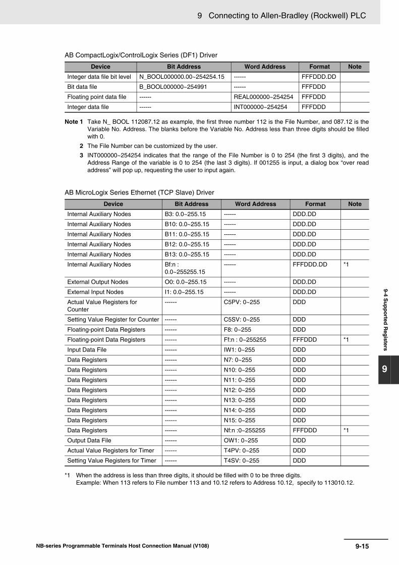
9-15
9 Connecting to Allen-Bradley (Rockwell) PLC
NB-series Programmable Terminals Host Connection Manual (V108)
9-4 Supported R
egisters
9
AB CompactLogix/ControlLogix Series (DF1) Driver
Note 1 Take N_ BOOL 112087.12 as example, the first three number 112 is the File Number, and 087.12 is theVariable No. Address. The blanks before the Variable No. Address less than three digits should be filledwith 0.
2 The File Number can be customized by the user.
3 INT000000~254254 indicates that the range of the File Number is 0 to 254 (the first 3 digits), and theAddress Range of the variable is 0 to 254 (the last 3 digits). If 001255 is input, a dialog box “over readaddress” will pop up, requesting the user to input again.
AB MicroLogix Series Ethernet (TCP Slave) Driver
*1 When the address is less than three digits, it should be filled with 0 to be three digits.Example: When 113 refers to File number 113 and 10.12 refers to Address 10.12, specify to 113010.12.
Device Bit Address Word Address Format Note
Integer data file bit level N_BOOL000000.00~254254.15 ------ FFFDDD.DD
Bit data file B_BOOL000000~254991 ------ FFFDDD
Floating point data file ------ REAL000000~254254 FFFDDD
Integer data file ------ INT000000~254254 FFFDDD
Device Bit Address Word Address Format Note
Internal Auxiliary Nodes B3: 0.0~255.15 ------ DDD.DD
Internal Auxiliary Nodes B10: 0.0~255.15 ------ DDD.DD
Internal Auxiliary Nodes B11: 0.0~255.15 ------ DDD.DD
Internal Auxiliary Nodes B12: 0.0~255.15 ------ DDD.DD
Internal Auxiliary Nodes B13: 0.0~255.15 ------ DDD.DD
Internal Auxiliary Nodes Bf:n : 0.0~255255.15
------ FFFDDD.DD *1
External Output Nodes O0: 0.0~255.15 ------ DDD.DD
External Input Nodes I1: 0.0~255.15 ------ DDD.DD
Actual Value Registers for Counter
------ C5PV: 0~255 DDD
Setting Value Register for Counter ------ C5SV: 0~255 DDD
Floating-point Data Registers ------ F8: 0~255 DDD
Floating-point Data Registers ------ Ff:n : 0~255255 FFFDDD *1
Input Data File ------ IW1: 0~255 DDD
Data Registers ------ N7: 0~255 DDD
Data Registers ------ N10: 0~255 DDD
Data Registers ------ N11: 0~255 DDD
Data Registers ------ N12: 0~255 DDD
Data Registers ------ N13: 0~255 DDD
Data Registers ------ N14: 0~255 DDD
Data Registers ------ N15: 0~255 DDD
Data Registers ------ Nf:n :0~255255 FFFDDD *1
Output Data File ------ OW1: 0~255 DDD
Actual Value Registers for Timer ------ T4PV: 0~255 DDD
Setting Value Registers for Timer ------ T4SV: 0~255 DDD

9 Connecting to Allen-Bradley (Rockwell) PLC
9-16 NB-series Programmable Terminals Host Connection Manual (V108)
9-5 Cable Fabrication
RS232 Communication Cable for MicroLogix• Communication Cable (Cat.No.: 1761-CBL-PM02) manufactured by Rockwell Automation, Inc.
• ALC +Advanced Interface Converter (Cat.No.:1761-NTE-AIC) and RS232 Communication Cable
RS232 Communication Cable for SLC 5 / 03
RS232 Communication Cable for CompactLogix/ControlLogix
Use Twisted Pair Cable to connect. Refer to Ethernet communication specifications in A-1-3 Communi-cation Specifications in the NB-series Programmable Terminals Setup Manual (Cat. No. V107).
Serial Communication Cable
Ethernet Communication Cable
PT (COM1/COM2)Pin No.
239
SignalSDRDSG
D-Sub9Pin
(Female)
PLCPin No.
325
SignalRXDTXDSG
78
RTSCTS
D-Sub9Pin
(Female)
PT (COM1/COM2)Pin No.
239
SignalSDRDSG
D-Sub 9Pin
(Female)
Micrologix series AIC-terminalPin No.
235
SignalRXDTXDGND
D-Sub 9Pin
(Female)
PT (COM1/COM2)Pin No.
239
SignalSDRDSG
D-Sub 9Pin
(Female)
PLCPin No.
235
SignalRXDTXDGND
D-Sub 9Pin
(Female)
PT (COM1/COM2)Pin No.
239
SignalSDRDSG
D-Sub 9Pin
(Female)
PLC CH0/CH1 terminalPin No.
235
SignalRXDTXDGND
D-Sub 9Pin
(Male)

10-1NB-series Programmable Terminals Host Connection Manual (V108)
10
This section describes the connection to PLC of GE Fanuc Automation Inc.
10-1 Serial Port Communication . . . . . . . . . . . . . . . . . . . . . . . . . . . . . . . . . . . . . . . . .10-2
10-2 Serial Port Communication Parameters and Cable Fabrication . . . . . . . . . . .10-3
10-3 Serial Port Communication Parameter Setting . . . . . . . . . . . . . . . . . . . . . . . . .10-4
10-4 Supported Registers . . . . . . . . . . . . . . . . . . . . . . . . . . . . . . . . . . . . . . . . . . . . . .10-7
10-5 Cable Fabrication . . . . . . . . . . . . . . . . . . . . . . . . . . . . . . . . . . . . . . . . . . . . . . . . .10-8
Connecting to PLC of GE Fanuc Automation Inc.

10 Connecting to PLC of GE Fanuc Automation Inc.
10-2 NB-series Programmable Terminals Host Connection Manual (V108)
10-1 Serial Port Communication
* Series 90 Product Supporting Break-free SNP Feature is as follows:
Note When you use the above-mentioned CPU(s) for communication, be sure to update it (them) to the specified version(s) inorder to make communications with GE Fanuc Series SNP protocol.
Series CPU Link Module Driver
GE Fanuc Series 90-30 IC693CPU311IC693CPU313IC693CPU321IC693CPU323IC693CPU331IC693CPU341IC693CPU350IC693CPU351IC693CPU352IC693CPU360IC693CPU363IC693CPU364IC693CPU374IC693CSE311IC693CSE313IC693CSE323IC693CSE331IC693CSE340
Serial Connector on Power Supply GE Fanuc Series SNP(Break-free mode)*
IC693CPU311IC693CPU313IC693CPU321IC693CPU323IC693CPU331IC693CPU340IC693CPU341IC693CPU350IC693CPU360IC693CPU364
Connector on Power Supply GE SNP-X
IC693CMM311
IC693CPU351IC693CPU352IC693CPU363
Connector on Power Supply
Port1 on CPU unit
Port2 on CPU unit
IC693CMM311
IC693CPU374 Port on Power Supply
IC693CMM311
VersaMax Series CPU001/002/005CPUE05
RS232 on port1
RS422 on port2
VersaMax Micro & Nano Series
IC200UAL004/005/006IC200UDD110/120/212IC200UDR005/006/010IC200UAA007IC200UAR028
RS232 on port1
RS422 on port2
Product Break-free SNP
Series 90-30 CPU350-364 Support on all serial communication ports starting with firmware release 9.00
Series 90-30 CPU311, 313, 323, 331, 341 Supported starting with firmware release 8.20

10-3
10 Connecting to PLC of GE Fanuc Automation Inc.
NB-series Programmable Terminals Host Connection Manual (V108)
10-2 Serial P
ort Com
munication
Param
eters and Cable
10
10-2 Serial Port Communication Parameters and Cable Fabrication
Series CPU Link Module COMM Type Parameter Cable
GE Fanuc Series 90-30
IC693CPU374 RS422 on the CPU unit
RS232 Refer to Section 10-3 Self-made cable requiredRS422
IC693CMM311 RS232
RS422
VersaMax Series
CPU001/002/005 RS232 on port1 RS232
RS422 on port2 RS422
VersaMax Micro & Nano Series
IC200UAL004/005/006IC200UDD110/120/212IC200UDR005/006/010IC200UAA007IC200UAR028
RS232 on port1 RS232
RS422on port2 RS422

10 Connecting to PLC of GE Fanuc Automation Inc.
10-4 NB-series Programmable Terminals Host Connection Manual (V108)
10-3 Serial Port Communication Parameter Setting
Default communication parameters for GE Fanuc Series SNP Protocol: 19200 (Baud Rate), 8 (DataBit), odd (Parity), 1 (Stop Bit), 1 (Station No.).
RS232 Communication
RS422 Communication
PT Settings

10-5
10 Connecting to PLC of GE Fanuc Automation Inc.
NB-series Programmable Terminals Host Connection Manual (V108)
10-3 Serial P
ort Com
munication
Param
eter Setting
10
Default communication parameters for GE SNP-X Protocol: 19200 (Baud Rate), 8 (Data Bit), odd (Parity),1 (Stop Bit), 1 (Station No.).
RS232 Communication
RS422 Communication
Note The maximum baud rate for the communication with serial port of GE Host is 19200 bps.
Take the settings of IC693CPU331 and IC693CMM311 as example:
Select the PLC and devices with the correct models in the Proficy Machine Edition window and you cansee the default settings here. There is no need to change the settings unless for some special condi-tions. But please note the SNP settings. And it only needs to set the related parameters in the PT to bethe same as that herein.
PLC Settings
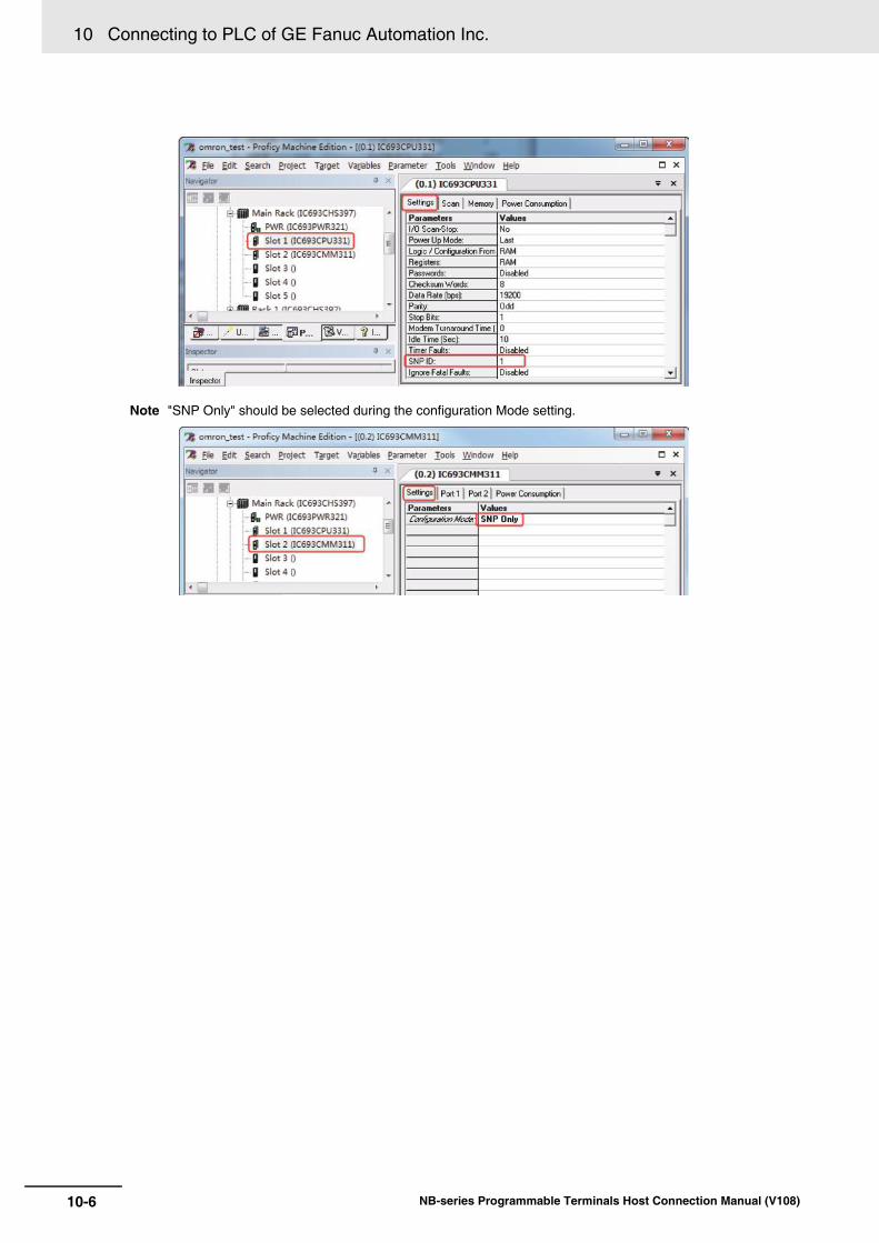
10 Connecting to PLC of GE Fanuc Automation Inc.
10-6 NB-series Programmable Terminals Host Connection Manual (V108)
Note "SNP Only" should be selected during the configuration Mode setting.

10-7
10 Connecting to PLC of GE Fanuc Automation Inc.
NB-series Programmable Terminals Host Connection Manual (V108)
10-4 Supported R
egisters
10
10-4 Supported Registers
Note Address format description: D: decimal, O: octonary, H: hexadecimal
Device Bit Address Word Address Format Notes
System SC 01~32 ------ DD
System SB 01~32 ------ DD
System SA 01~32 ------ DD
System S 01~32 ------ DD
Temporary T 001~256 ------ DDD
Internal M 0001~4096 ------ DDDD
Genius Global G 0001~1280 ------ DDDD
Output Q 0001~2048 ------ DDDD
Input I 001~256 ------ DDD
Analog Output ------ AQ 001~512 DDD
Analog Input ------ AI 0001~2048 DDDD
Register ------ R 0001~9999 DDDD

10 Connecting to PLC of GE Fanuc Automation Inc.
10-8 NB-series Programmable Terminals Host Connection Manual (V108)
10-5 Cable Fabrication
RS232 Communication for GE Fanuc Series SNPCommunicating with PT by directly using the communication cable provided by GE
RS232 Communication for VersaMax Series
RS232 Communication for VersaMax Micro & Nano Series
RS232 Communication Cable for Communication Module CMM311
PT (COM1/COM2)Pin No.
239
SignalSDRDSG
D-Sub 9Pin
(Female)
VersaMax series PLC Pin No.
325
SignalRDTD
GND
D-Sub 9Pin
(Female)
PT (COM1/COM2)Pin No.
239
SignalSDRDSG
D-Sub 9Pin
(Female)
VersaMax Micro&Nano series PLCPin No.
651
SignalRXTX
GND
RJ45 terminal
PT (COM1/COM2)Pin No.
239
SignalSDRDSG
D-Sub 9Pin
(Female)
CMM311 port1/port2 teminalPin No.
327
SignalRXDTXDGND D-Sub
25Pin(Female)4
58
RTSCTSDCD
20 DTR

10-9
10 Connecting to PLC of GE Fanuc Automation Inc.
NB-series Programmable Terminals Host Connection Manual (V108)
10-5 Cable Fabrication
10
RS422 Communication Cable for Communication Module CMM311
RS422 Communication for 90-30/VersaMax
PT (COM2)Pin No.
167
SignalSDB+RDB+SDA-D-Sub
9Pin(Female)
CMM311 port2 terminalPin No.
252113
SignalRDBSDBRDA
D-Sub 25Pin
(Female)
89
RDA-SG
4Terminal R15
97
SDAGND
1011
RTSACTSA
1222
TER CTSRTSB
23 CTSB
Terminal R2
PT (COM2)Pin No.
167
SignalSDB+RDB+SDA-
D-Sub 9Pin
(Female)
PLCPin No.
111310
SignalRDBSDBRDA
D-Sub 15Pin
(Female)
89
RDA-SG
45
Terminal R1Terminal R2
127
SDAGND
98
RTSACTSA
146
TER CTSRTSB
15 CTSB

10 Connecting to PLC of GE Fanuc Automation Inc.
10-10 NB-series Programmable Terminals Host Connection Manual (V108)

11-1NB-series Programmable Terminals Host Connection Manual (V108)
11
This section describes methods to connect to Keyence PLCs.
11-1 Serial Port and the Ethernet . . . . . . . . . . . . . . . . . . . . . . . . . . . . . . . . . . . . . . . .11-2
11-2 Communication Setting and Cable Connection . . . . . . . . . . . . . . . . . . . . . . . .11-3
11-3 Communication Setting . . . . . . . . . . . . . . . . . . . . . . . . . . . . . . . . . . . . . . . . . . . .11-411-3-1 When Using Keyence KV-3000 Communication Protocol . . . . . . . . . . . . . . . 11-411-3-2 When Using Keyence KV-5000 EtherNetSlave Communication Protocol . . . 11-5
11-4 Supported Registers . . . . . . . . . . . . . . . . . . . . . . . . . . . . . . . . . . . . . . . . . . . . . .11-7
11-5 Cable Connection . . . . . . . . . . . . . . . . . . . . . . . . . . . . . . . . . . . . . . . . . . . . . . . . .11-8
Connecting to Keyence PLCs

11 Connecting to Keyence PLCs
11-2 NB-series Programmable Terminals Host Connection Manual (V108)
11-1 Serial Port and the Ethernet
* This Protocol supports Multiple Station No.
Series CPU Link Module Driver
KV-3000
KV-3000 CPU RS232 Port on CPU Unit KeyenceKV-3000
KV-5000
KV-5000 CPU Ethernet Port on CPU Unit KeyenceKV-5000 EtherNetSlave
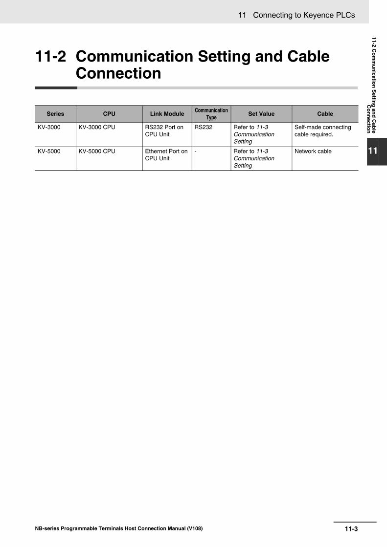
11-3
11 Connecting to Keyence PLCs
NB-series Programmable Terminals Host Connection Manual (V108)
11-2 Com
munication S
etting and Cable
Connection
11
11-2 Communication Setting and Cable Connection
Series CPU Link Module Communication Type Set Value Cable
KV-3000 KV-3000 CPU RS232 Port on CPU Unit
RS232 Refer to 11-3 Communication Setting
Self-made connecting cable required.
KV-5000 KV-5000 CPU Ethernet Port on CPU Unit
- Refer to 11-3 Communication Setting
Network cable

11 Connecting to Keyence PLCs
11-4 NB-series Programmable Terminals Host Connection Manual (V108)
11-3 Communication Setting
PT default communication parameters: 9600bps (Baud Rate), 8 (Data Bit), even (Parity Check) and 1(Stop Bit)
As showed in the right of dialog box as below, PLC Communication Time Out, Max interval of wordblock pack, Max interval of bit block pack, Max word block package are varied with PLC protocol. Gen-erally, the default values are selected.
RS232 Communication
Note The Baud Rate supports 9600, 19200, 38400, 57600 and 115200.
When Keyence KV-3000 Communication Protocol is used, the setting of PLC is not required.
11-3-1 When Using Keyence KV-3000 Communication Protocol
PT Settings
PLC Settings

11-5
11 Connecting to Keyence PLCs
NB-series Programmable Terminals Host Connection Manual (V108)
11-3 Com
munication S
etting
11
11-3-2 When U
sing Keyence K
V-5000 E
therNetS
lave Com
munication P
rotocol
The PT Network Setting is shown as follows.
11-3-2 When Using Keyence KV-5000 EtherNetSlave Communication Protocol
PT Setting
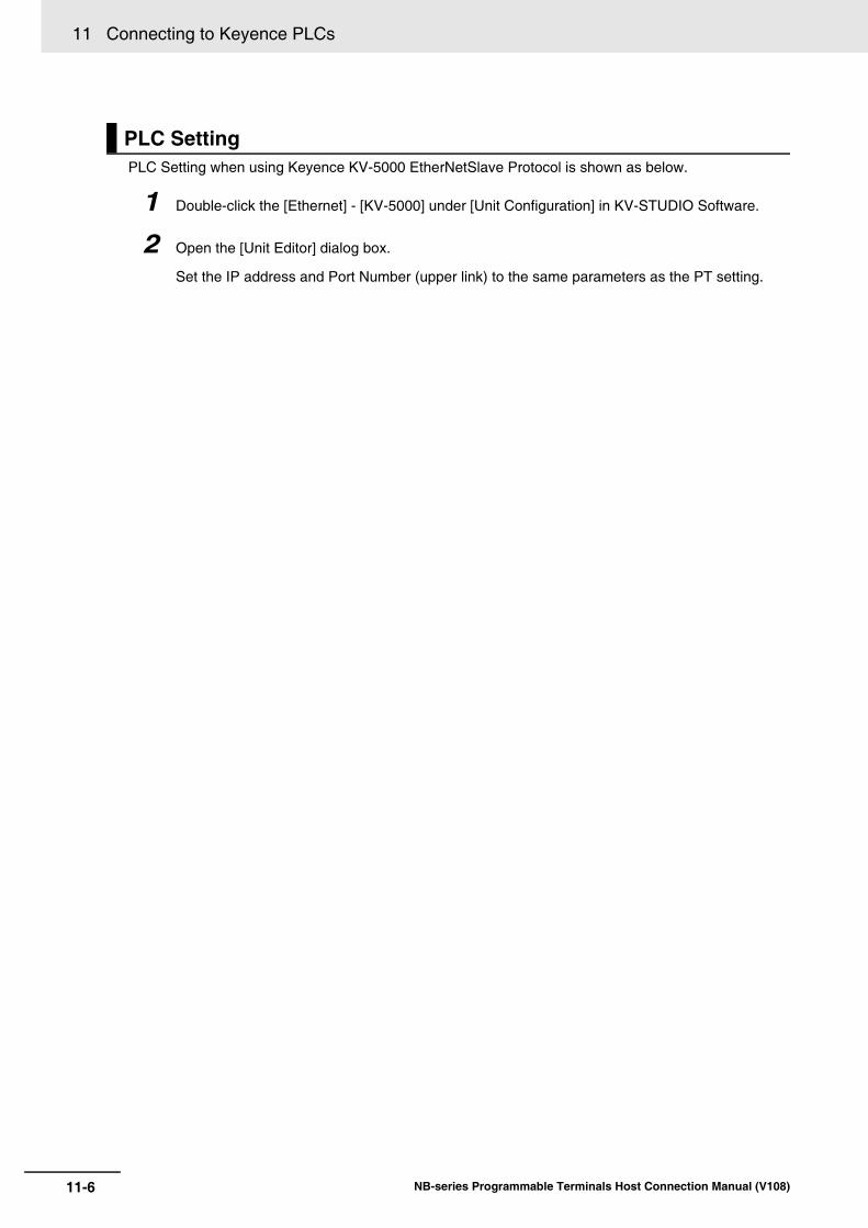
11 Connecting to Keyence PLCs
11-6 NB-series Programmable Terminals Host Connection Manual (V108)
PLC Setting when using Keyence KV-5000 EtherNetSlave Protocol is shown as below.
1 Double-click the [Ethernet] - [KV-5000] under [Unit Configuration] in KV-STUDIO Software.
2 Open the [Unit Editor] dialog box.
Set the IP address and Port Number (upper link) to the same parameters as the PT setting.
PLC Setting
11-7
11 Connecting to Keyence PLCs
NB-series Programmable Terminals Host Connection Manual (V108)
11-4 Supported R
egisters
11
11-4 Supported Registers
KV-3000
KV-5000
Device Bit Address Word Address Format Notes
Input, Output, Internal Relay
R0-999.15 ------ DDD.DD
Internal auxiliary Relay MR0-999.15 ------ DDD.DD
Control Relay CR0-39.15 ------ DD.DD
Latch Relay LR0-999.15 ------ DDD.DD
Data Memory ------ DM0-65534 DDDDD
Extended Data Memory
------ EM0-65534 DDDDD
Temporary Data Memory
------ TM0-511 DDD
Control Memory ------ CM0-5999 DDDD
File Register ------ FM0-32767 DDDDD

11 Connecting to Keyence PLCs
11-8 NB-series Programmable Terminals Host Connection Manual (V108)
11-5 Cable Connection
RS-232 Communication Cable
Use Twisted Pair Cable to connect. Refer to Ethernet communication specifications in A-1-3 Communi-cation Specifications in the NB-series Programmable Terminals Setup Manual (Cat. No. V107).
KV-3000 Series RS232 Communication Cable
KV-5000 Series Ethernet Communication Cable
PT (COM1/COM2)Pin No.
239
SignalSDRDSG
D-Sub9 PIN
(Female)
PLCPin No.
534
Signal
SG
SDRD
RJ-12(Female)

12-1NB-series Programmable Terminals Host Connection Manual (V108)
12
This section describes the method to connect to OMRON Safety Controller.
12-1 Serial Port . . . . . . . . . . . . . . . . . . . . . . . . . . . . . . . . . . . . . . . . . . . . . . . . . . . . . . .12-2
12-2 Communication Parameters and Cable Fabrication . . . . . . . . . . . . . . . . . . . . .12-3
12-3 Communication Parameter Setting . . . . . . . . . . . . . . . . . . . . . . . . . . . . . . . . . . .12-412-3-1 When using OMRON G9SP Communication Protocol . . . . . . . . . . . . . . . . . 12-4
12-4 Supported Registers . . . . . . . . . . . . . . . . . . . . . . . . . . . . . . . . . . . . . . . . . . . . . .12-6
12-5 Cable Connection . . . . . . . . . . . . . . . . . . . . . . . . . . . . . . . . . . . . . . . . . . . . . . . . .12-7
Connecting to OMRON Safety Controller

12 Connecting to OMRON Safety Controller
12-2 NB-series Programmable Terminals Host Connection Manual (V108)
12-1 Serial Port
* Model CP1W-CIF01 is needed.
Series CPU Destination Driver
G9SP G9SP-N10SG9SP-N10DG9SP-N20S
RS-232C Connector of Option Board mounted to the Safety Controller*
OMRON G9SP

12-3
12 Connecting to OMRON Safety Controller
NB-series Programmable Terminals Host Connection Manual (V108)
12-2 Com
munication P
arameters and C
able Fabrication
12
12-2 Communication Parameters and Cable Fabrication
Series CPU Destination Communication Type Set Value Cable
G9SP G9SP RS-232C Connector of Option Board mounted on the Safety Controller
RS232 Refer to 12-3 Communication Parameter Setting
XW2Z-200T 2mXW2Z-500T 5m

12 Connecting to OMRON Safety Controller
12-4 NB-series Programmable Terminals Host Connection Manual (V108)
12-3 Communication Parameter Setting
PT default communication parameters: 9600bps (Baud Rate), 8 (Data Bit), even number (ParityCheck) and 1 (Stop Bit)As showed in the right of dialog box as follow, the default values are generally selected to PLC Communication Time Out, Max interval of word block package, Max interval of bit block pack, and Maxsize of word block package.
RS232 Communication
Note G9SP Serial Communication Protocol only supports communication speed of 9600bps.
12-3-1 When using OMRON G9SP Communication Protocol
PT Settings

12-5
12 Connecting to OMRON Safety Controller
NB-series Programmable Terminals Host Connection Manual (V108)
12-3 Com
munication P
arameter S
etting
12
12-3-1 When using O
MR
ON
G9S
P C
omm
unication Protocol
When OMRON G9SP Communication Protocol is used, the setting of PLC is not required.
Precautions for Correct UsePrecautions for Correct Use
For the specification of G9SP protocol, write occurs when the NB series startup.
Therefore, from the NB series startup until the value is set to the WD area, initial value 0 is writ-ten to "Optional Communications Reception Data" of G9SP.
When "Optional Communications Reception Data" of G9SP is used in the program of G9SP, fol-low the indications to avoid accidental writing the initial value 0 from the NB series.• When the NB series or power supply is restarted during the G9SP operation, make sure that
no influences to the G9SP to perform it. • After set the initial value to the WD area with the Macro and arrange the components which
can execute the Macro when timer component or others startup in startup screen, set thevalue of the WD area before write occurs.
Also be aware of the initial value 0 which is written from the NB series even at G9SP to designthe program.
PLC Settings

12 Connecting to OMRON Safety Controller
12-6 NB-series Programmable Terminals Host Connection Manual (V108)
12-4 Supported Registers
Transmission Data (G9SP Series PT)
Reception Data (PT G9SP Series)
Additional Information
In the case of a byte device or a nibble device, insufficient byte to the Word length are to be filledwith 0.Example: In the communication data, when the sent data is 0x12345678 and upper bytes areread as the byte device, all the bytes are displayed as 0x00001234.
Device Bit Address(format DD)
Word Address(format DD) Notes
Optional Communications Transmission Data
CTD 0-31 -----
Safety Input Terminal Data Flags SID 0-47 -----
Safety Output Terminal Data Flags SOD 0-31 -----
Safety Input Terminal Status Flags SIS 0-47 -----
Safety Output Terminal Status Flags SOS 0-31 -----
Safety Input Terminal Error Causes ----- SIE 0-47 Nibble device
Safety Output Terminal Error Causes ----- SOE 0-31 Nibble device
Reserved ----- RES1 0-1 Byte device
Unit Status and Echo-back USE 0-15 -----
Configuration ID ----- CID 0-0
Unit Conduction Time ----- UCT 0-0 Double word device
Reserved ----- RES2 0-19 Byte device
Present Error Information ----- PEI 0-11 Byte device
Error Log Count ----- ELC 0-0 Byte device
Operation Log Count ----- OLC 0-0 Byte device
Error Log ----- EL 0-9 Double word device
Operation Log ----- OL 0-9 Double word device
Device Bit Address(format DD)
Word Address(format DD) Notes
Optional Communication Reception Data WD_Bit 0-31 WD 0-1
12-7
12 Connecting to OMRON Safety Controller
NB-series Programmable Terminals Host Connection Manual (V108)
12-5 Cable C
onnection
12
12-5 Cable Connection
RS-232 Communication CableUse either of cables recommended for the communication cable.
XW2Z-200T (cable length 2m) manufactured by OMRON
XW2Z-500T (cable length 5m) manufactured by OMRON

12 Connecting to OMRON Safety Controller
12-8 NB-series Programmable Terminals Host Connection Manual (V108)

Revision-1NB-series Programmable Terminals Host Connection Manual (V108)
Revision History
A manual revision code appears as a suffix to the catalog number on the front cover of the manual.
Revision code Date Revised content
01 October 2011 Original production
02 April 2012 Adding descriptions of Modbus network interface communication and Modbus protocol.
03 August 2012 Adding descriptions of connecting to PLCs manufactured by Allen-Bradley and GE Fanuc Automation INC.
04 December 2012 Correction related to the backlight lamp and rubber packing maintenance in Precautions for Safe Use.
05 December 2012 • Adding descriptions of the power supply and wire connection in Precautions for Safe Use.
• Adding descriptions of the serial port COM.• Adding descriptions of E5CC/E5EC and 3G3MX2
connection using Modbus protocol.
06 April 2013 Changes and corrections
07 August 2013 Adding descriptions of support models
08 November 2013 Changes and corrections
09 February 2014 Adding descriptions of support models
10 July 2014 Adding descriptions of support models
11 October 2014 Adding descriptions of support models
12 April 2016 Changes and corrections
13 October 2016 Changes and corrections
Cat. No. V108-E1-
Revision code

Revision-2 NB-series Programmable Terminals Host Connection Manual (V108)


Authorized Distributor:
In the interest of product improvement, specifications are subject to change without notice.
1016
© OMRON Corporation 2011-2016 All Rights Reserved.
OMRON Corporation Industrial Automation Company
OMRON ELECTRONICS LLC2895 Greenspoint Parkway, Suite 200 Hoffman Estates, IL 60169 U.S.A.Tel: (1) 847-843-7900/Fax: (1) 847-843-7787
Regional HeadquartersOMRON EUROPE B.V.Wegalaan 67-69, 2132 JD HoofddorpThe NetherlandsTel: (31)2356-81-300/Fax: (31)2356-81-388
Contact: www.ia.omron.comKyoto, JAPAN
OMRON ASIA PACIFIC PTE. LTD.No. 438A Alexandra Road # 05-05/08 (Lobby 2), Alexandra Technopark, Singapore 119967Tel: (65) 6835-3011/Fax: (65) 6835-2711
OMRON (CHINA) CO., LTD.Room 2211, Bank of China Tower, 200 Yin Cheng Zhong Road, PuDong New Area, Shanghai, 200120, ChinaTel: (86) 21-5037-2222/Fax: (86) 21-5037-2200 Cat. No. V108-E1-13