hotspot: a dynamic compact thermal model at the …skadron/papers/hotspot_mej.pdf · hotspot: a...
TRANSCRIPT

HotSpot: a Dynamic Compact Thermal Model at theProcessor-Architecture Level
MirceaR. Stan�, Kevin Skadron
�, MarcoBarcella
�, Wei Huang
�,
Karthik Sankaranarayanan�, andSivakumarVelusamy
��Dept. of Electrical and Computer Engineering�
Dept. of Computer Science
University of Virginia
Charlottesville, VA 22904
Accepted for the Special issue on Therminic 2002 as paper T02MEJ 14
Abstract
This paperdescribesa thermal-modelingapproachthatis easyto useandcomputationallyefficient for modelingthermaleffectsandthermal-managementtechniquesat theprocessorarchitecturelevel. Our approachis basedon modelingthermalbehavior of themicropro-cessordie andits packageasa circuit of thermalresistancesandcapacitancesthat corre-spondto functionalblocksat the architecturelevel. This yields a simplecompactmodel,yet heatdissipationwithin all majorfunctionalblocksandtheheatflow amongblocksandthroughthepackageareaccountedfor. Themodelis parameterized,boundary-andinitial-conditionsindependent,andis derivedby a structureassemblyapproach.Thearchitecturecommunityhasdemonstratedgrowing interestin thermalmanagement,but currentlylacksa way to modelon-chiptemperaturesin a tractableway. Our modelcanbeusedfor initialexplorationof thedesignspaceat thearchitecturelevel. Themodelcaneasilybeintegratedinto popularpower/performancesimulators,canbeusedto determinehow thermalstressiscorrelatedto thearchitecture,andhow architecture-level designdecisionsinfluencethermalbehavior andrelatedeffects.
Key words: Thermalmodels,Dynamiccompactmodels,ComputerArchitecture
1 Introduction
Many analystssuggestthat increasingpower densityandresultingdifficulties inmanagingon-chip temperaturesaresomeof the mosturgentobstaclesto contin-ued scalingof VLSI systemswithin the next five to ten years.Justas hasbeen
Preprintsubmittedto Elsevier Science 1 June2003
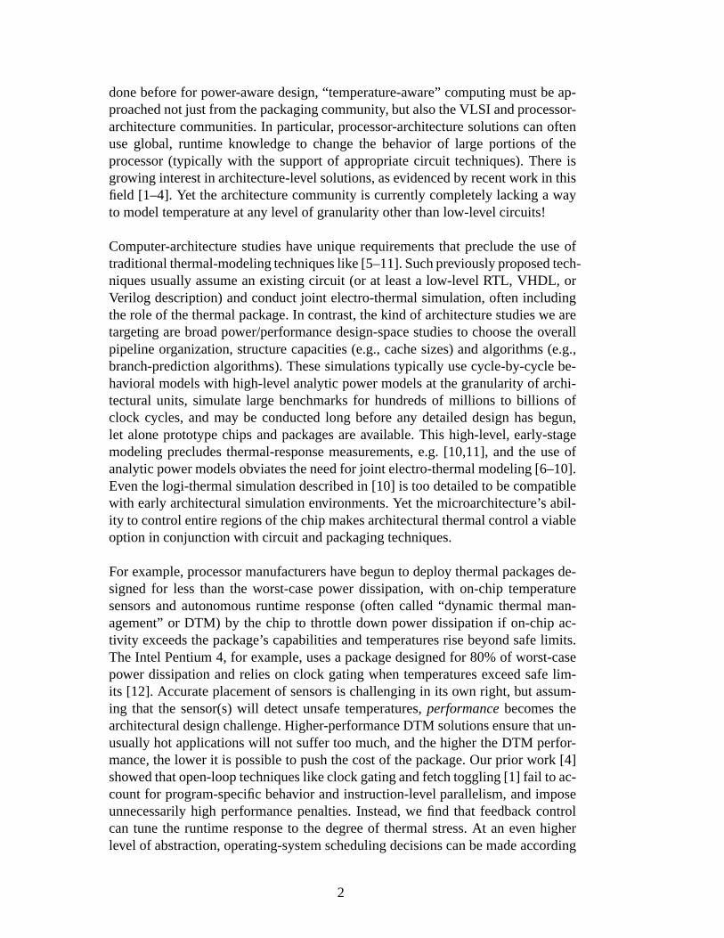
donebeforefor power-awaredesign,“temperature-aware” computingmustbeap-proachednot just from thepackagingcommunity, but alsotheVLSI andprocessor-architecturecommunities.In particular, processor-architecturesolutionscanoftenuseglobal, runtime knowledgeto changethe behavior of large portionsof theprocessor(typically with the supportof appropriatecircuit techniques).Thereisgrowing interestin architecture-level solutions,asevidencedby recentwork in thisfield [1–4]. Yet thearchitecturecommunityis currentlycompletelylackinga wayto modeltemperatureat any level of granularityotherthanlow-level circuits!
Computer-architecturestudieshave uniquerequirementsthat precludethe useoftraditionalthermal-modelingtechniqueslike[5–11].Suchpreviouslyproposedtech-niquesusuallyassumean existing circuit (or at leasta low-level RTL, VHDL, orVerilog description)andconductjoint electro-thermalsimulation,often includingtherole of thethermalpackage.In contrast,thekind of architecturestudieswe aretargetingarebroadpower/performancedesign-spacestudiesto choosetheoverallpipelineorganization,structurecapacities(e.g.,cachesizes)andalgorithms(e.g.,branch-predictionalgorithms).Thesesimulationstypically usecycle-by-cycle be-havioral modelswith high-level analyticpower modelsat thegranularityof archi-tecturalunits, simulatelarge benchmarksfor hundredsof millions to billions ofclock cycles,andmay be conductedlong beforeany detaileddesignhasbegun,let aloneprototypechipsandpackagesareavailable.This high-level, early-stagemodelingprecludesthermal-responsemeasurements,e.g. [10,11], andthe useofanalyticpowermodelsobviatestheneedfor joint electro-thermalmodeling[6–10].Eventhelogi-thermalsimulationdescribedin [10] is too detailedto becompatiblewith earlyarchitecturalsimulationenvironments.Yet themicroarchitecture’s abil-ity to controlentireregionsof thechipmakesarchitecturalthermalcontrolaviableoptionin conjunctionwith circuit andpackagingtechniques.
For example,processormanufacturershave begunto deploy thermalpackagesde-signedfor lessthan the worst-casepower dissipation,with on-chip temperaturesensorsand autonomousruntime response(often called “dynamic thermalman-agement”or DTM) by the chip to throttle down power dissipationif on-chipac-tivity exceedsthepackage’s capabilitiesandtemperaturesrisebeyondsafelimits.TheIntel Pentium4, for example,usesa packagedesignedfor 80%of worst-casepower dissipationandrelieson clock gatingwhentemperaturesexceedsafelim-its [12]. Accurateplacementof sensorsis challengingin its own right, but assum-ing that the sensor(s)will detectunsafetemperatures,performance becomesthearchitecturaldesignchallenge.Higher-performanceDTM solutionsensurethatun-usuallyhot applicationswill not suffer too much,andthehighertheDTM perfor-mance,thelower it is possibleto pushthecostof thepackage.Our prior work [4]showedthatopen-looptechniqueslikeclockgatingandfetchtoggling[1] fail to ac-countfor program-specificbehavior andinstruction-level parallelism,andimposeunnecessarilyhigh performancepenalties.Instead,we find that feedbackcontrolcantunethe runtimeresponseto the degreeof thermalstress.At an even higherlevel of abstraction,operating-systemschedulingdecisionscanbemadeaccording
2

to currentoperatingtemperaturesandobservationsof eachthread’s thermalbehav-ior [3]. Ultimately, theseoperating-systemandmicro-architecturetechniqueswillbecombined,especiallyin chip-multiprocessorswhere“core-hopping”canbeusedto matchworkloadsto per-chip andper-structuretemperatures.
Oneobstacleto thiskind of work is thelackof thermalsimulatorsthatareamenableto usein high-level architectureresearchenvironments.Yet theaccuracy of thermalmodelinghasa substantialeffect on the accuracy of thermal-managementstud-ies at the processor-architecturelevel andthe conclusionsthey draw [4]. Withoutthis essentialmodelingcapability, architectureresearchersarethereforelimited tocrudeandinaccurateestimationtechniquesandareunableto effectively developandevaluatetechniquesfor thermalmanagement.For example,we show thatsim-plistic thermalestimationbasedonsimpleaveragesof runtimepowerdensityusingarchitecture-level analyticalpower modelslike [13] yieldspooraccuracy andmayeventargetthewrongarchitecturalstructures.
A thermalmodelthatprocessorarchitectscanuseto evaluatethermalbehavior ofvariousdesigns,or to developruntimearchitecturetechniquesfor thermalresponse,thereforenecessitatesa parameterized,“a priori” thermalmodelingapproachthatcandirectly modeltemperatureusingonly a high-level modelof theprocessorar-chitectureand that can be automaticallyconfiguredto simulatea wide rangeofarchitectures.Themodelshouldthereforebebasedpurelyon geometricconsider-ationsandmaterialproperties,andthedynamicsimulationshouldonly dependondynamicinformationaboutpowerdensityin eacharchitecturalunit.
This paperdescribesHotSpot, a thermalmodelingframework for processorarchi-tectsthat meetsthesegoalsandcanbe incorporatedinto popularcycle-accurateprocessor-architecturepower/performancesimulatorslike Wattch [13]. HotSpotconsistsof four majorparts:
(1) HotArea: A modulethat estimateson-chip areasfor the major blocks of aspecifiedmicroprocessorconfiguration.
(2) HotFloorplan: A modulethatusesthe specifiedprocessorconfigurationandthecorrespondingareaestimatesto deriveahigh-level floorplan.
(3) HotPackage: A modulethat estimatesan equivalent thermalresistanceandcapacitancefor aspecifiedpackageconfiguration.
(4) HotBlocks: A modulethatderives—usinginput from theabove threesteps—anequivalentdynamiccompactmodelto approximateheatflow in themicro-processorandits package.Themodelcanbecharacterizedasaparameterized,boundaryandinitial-conditionsindependent(BICI) dynamiccompactthermalmodelderivedwith a structureassemblyapproach[14]. Themodelis simpleandthereforecomputationallyefficient to recomputeafter every clock cyclein a cycle-level power-performancesimulator.
Theseareintegratedinto a portablesoftwarepackagethat caneasilybe incorpo-
3

ratedinto architecture-level simulators.
This work focuseson modelingheatdissipationandheatflow—that is, actualon-chiptemperatures.Thiscanbeusedto determinehow thermalstressis correlatedtothearchitecture,andhow architecturaldesigndecisionsinfluencethermalbehaviorandrelatedeffectslike reliability andleakagecurrents(leakage-controltechniqueshave becomea major areaof investigationin processorarchitecture,despitethelack of temperature-awaremodels).Clearly this approachentailsa numberof ap-proximationsand is not meantto replaceother forms of thermalsimulationforcircuit or packagedesign.Rather, HotSpotallows early-stagearchitectureexplo-rationsthat facilitatearchitecture-level thermalsolutionsthat aresynergistic withthermalsolutionsat otherlevelsof abstraction.
This paperreportsour ongoingwork to developandrefineHotSpot.Thenext sec-tion givesanoverview of ourapproachto modelingdynamicthermalbehavior fromthearchitecturestandpoint,andsubsequentsectionsdescribethefour componentsof theHotSpotframework. We describetheHotAreaandHotPackagecomponentsbriefly; themainfocusof this paperis a descriptionanddemonstrationof theHot-FloorplanandHotBlockstechniques.Finally, we concludethe paperanddiscussareasfor futurework.
2 Thermal Modeling at the Processor Architecture Level
For the kinds of studieswe intend to pursue,the compactmodelmust have thefollowing properties:� It must track temperaturesat the granularityof individual pipelineunits. This
meanstheequivalentRC circuit musthaveat leastonenodefor eachunit.� It mustbe computationallyefficient to solve the RC circuit’s differentialequa-tions,sothatthis taskdoesnotsubstantiallyslow down power/performancesim-ulations.� It mustbeparameterized,in thesensethatanew compactmodelis automaticallygeneratedfor differentmicroarchitectures.� It mustbe portable,making it easyto usewith a rangeof power/performancesimulators.� It must be boundary-and initial-condition independent(BICI) [14]. The ther-mal modelcomponentvaluesshouldnot dependon initial temperaturesor theparticularconfigurationbeingstudied.� It mustbe calibratedso that simulatedtemperaturescanbe expectedto corre-spondto whatwouldbeobservedin realhardware.
Themodelwe have developed,which we call HotSpot,meetsall theseconditionsat the expenseof a reducedaccuracy comparedto moredetailedapproaches.For
4

an integratedcircuit at thedie level, heatconductionto thepackageandheatsink,andconvectionfrom the heatsink to ambientare the dominantmechanismsthatdeterminetemperaturesonthedie.Thereexistsawell-known dualitybetweenheattransferandelectricalphenomena[15]. Heatflow canbe describedasa current,andthepassingof thisheatflow throughathermalresistanceleadsto atemperaturedifferenceequivalentto a voltage.Thermalresistancesareenoughfor describingsteady-statebehavior, but dynamicbehavior is alsoimportantfor dynamicthermalmanagement,andthis requiresthermalcapacitancesaswell. Becauseof thermalcapacitances,evenwhenthepower flow changesinstantaneously, thereis a delaybeforethe temperaturechangesandreachessteadystate.The thermalresistancesandcapacitancestogetherleadto riseandfall timescharacterizedby thermaltimeconstantsexactlyanalogousto theelectricaltimeconstantsfor anRC circuit. Priorwork on thermalissuesin thearchitecturefield hasnotmodeledtemperatureatall,but ratheruseda mereaverageof power dissipationvaluesas a proxy. HotSpotprovidesa directmodelof temperature.It usestheduality betweenelectricalandthermalresistancesand capacitancesto derive a dynamiccompactmodelof theheatflow amongthe differentarchitecture-level blockswithin a microprocessor.Architecturalpower-performancesimulatorslike Wattch[13] canthenbe usedtodeterminecycle-by-cycle power dissipationsandfeedtheminto thecircuit modelto computecycle-by-cycleheatflow.
Large ICs have a heterogeneousstructurewith many different areason the dieworking at different activity factors,which implies that power is not dissipateduniformly on the chip. This spatial non-uniformity is complementedby a tempo-ral non-uniformity asmany structureson thedie go from idle modeto full activemode,and vice-versa,at different times.Recentemphasison low-power designtechniquessuchaspower-down modes,clock domainsandclock gating,etc.areonly exacerbatingthespatialandtemporalnon-uniformityfor on-chippower den-sity. As a resultof this non-uniformity, thechip will exhibit so-called“hot spots”.Thesehotspotshaveaspatialdistributionasa resultof thenon-zerothermalresis-tivity of silicon andalsoa temporaldistributiondueto changingprogrambehaviorandthetimeconstantsimplied by thethermalmass(thermalcapacitance).
In orderto derive a compactmodeloneneedsto decideon thelevel of granularityfor thelumpedelements.For pipeline-level modeling,weuseanaturalpartitioningwherefunctionalblocksonthechiparethenodesin thelumpedcircuit model.Thusthereis a one-to-onecorrespondencebetweenthe model in a power/performancesimulator like Wattch and the model in the thermalsimulator, which leadsto astraightforwardcouplingbetweenthetwo.
The equivalent-circuitmodel is dependenton the floorplanandpackagingof theprocessorbeing simulated,while the floorplan and the calculationof valuesforthermalresistanceand capacitanceare dependenton the areasof the functionalblocksof interest.
5

Althoughbeyondthescopeof this work, a completemodelingandevaluationtoolfor thermalmanagementmustaccountfor thebehavior of temperaturesensors aswell astheactualon-chiptemperatures.Our understandingis that theaccuracy ofmostpracticalsensordesignsis susceptibleto bothprocessvariationsduringman-ufacturingandpower-supplyvariations.Compensatingfor theserequiresincreasedtransistorsizesin the sensors,with correspondingincreasesin power. In currentmicroprocessors,this leadsto theuseof only a smallnumberof sensors,e.g.foursensorsdistributedaroundthedie. Becausethesesensorsmayberemotefrom thehotspotsof interest,theremaybea time lag betweenlocalizedheatingthatshouldgeneratea thermal-managementresponseandtheactualobservationof any changein temperatureat thesensor. An architecture-level modelof theseeffectswill even-tually beincorporatedinto HotSpot.
We reiteratethat our approachis motivatedby a microarchitecture-centricview-point.This meansthatwe neglecta numberof issuesthataretypically consideredin a full thermaldesign.For example,we completelyneglect thermalmodelingofthecircuit board,heatingof theair within thecomputersystemcase,temperaturenon-uniformitiesin the air, heatflow throughthe packagepins,etc.Becausemi-croarchitecturesimulationsonly modelvery small time periodsof perhapsa fewsecondsat most, thesecomponentsthat areexternal to the chip and its packagerespondtoo slowly to changetemperatureduringsuchshorttime scales,andtheseexternalcomponentsdonotcontributein asignificantwayto thecapacitancebeingdriven by the chip. Indeed,even the heatsink itself doesnot changetemperatureon thesetime scales,but it mustbe includedbecauseits capacitancedoesaffectthe transientbehavior of the chip. The intendedpurposeof HotSpotfor usewithmicroarchitecturesimulatorsalsodrivessomeof the approximationsandsimpli-ficationsthat we make. The purposeof HotSpotat this point in time is thereforenot to performreliability analysisor packagedesign,but ratherto allow researchinto microarchitecturetechniquesfor runtimemitigation of hotspotsthat developaccordingto the behavior of specificarchitecturalstructures,like register file orcacheactivity.
3 HotArea: Estimating Area for Microprocessor Functional Units
Efficientarchitecture-level thermalmodelingrequiresestimationof theareaof var-iousfunctionalunitsonchipbasedonarchitecturalparameters.Theareaestimationitself canalsoallow thedesignersto makemorecomprehensivedesignspacecom-parisonsin the early phaseof thedesignprocess.The area-estimationtool is stillin its early stages,andthe HotFloorplanandHotBlocksmodulescaninsteadusepublishedareainformationfor thetimebeing.
In this sectionwe give a brief overview of our strategy for areaestimation.Wedivide the blocks that constitutea microprocessorinto threecategories,accord-
6

ing to their regularity. The first classconsistsof structureswith two-dimensionalregularity, generallymemorystructures.Theseincludecaches,TLBs, registerfile,branchpredictor, load-storequeue,instruction-issuequeues,and active list. Thesecondclassconsistsof structureswith one-dimensionalregularity, generallybit-slice structures.Theseinclude all integer datapathand floating point units. Thethird classconsistsof irregular structures,generallycontrol logic. Theseincludethememory-managementunit,decodinglogic, register-renaminglogic, issuelogic,andgraduationlogic. We useanalyticmodelsto derive a “baseline”areafor eachblock from a known chip layout, and then use known measurementsfrom theknown layout to scalethis estimate.This scalingfactor can then be appliedforusingthe analyticmodelsto derive areaestimatesfor differentarchitectures.Forexample,oncethescalingfactorsfor first-level caches,ALUs, etc.areknown, dif-ferentarchitecturescanbeexploredwith larger/smallercaches,differentnumbersor typesof ALUs, etc.
We useanexisting tool, Cacti3.0 [16], to calculatetheareaof memorystructures;Cactiis in turnbasedon[17]. Areaestimationfor theregisterfile, queue,andcachestructurescanbeimplementedby simply inputtingtheproperparametersto Cacti.
Sincearithmeticunitscanbeimplementedin many differentways,weconsiderareaestimatorsfor themostcommonlyusedstructures.For example,in providing areamodelsfor adders,wemodelbothaKogge-StoneandaHan-Carlsonstructure[18],lettingtheuserschoosebetweenthem.Thedatapathis normallyonthecritical pathof the processor, so it requireshigh performance.We acceptas a parameterthekind of CMOScircuit (dynamic/static)usedto implementit andallow theusertospecifya sizing parameter, sincethe executionunits aremost likely sizedlargerthanminimumsize.
For irregular structures,we adoptthe modelproposedby Nemani[19]. First weneedan approximatebooleandescriptionof the structures,which is plausibletoderivefor decodingandatleastthemajoraspectsof memory-management,register-renaming,issue,andgraduation.Thenwe usethemodelto estimatethetransistornumber. Finally weuseaveragetransistordensityto estimatethearea.
Cacti is anexisting tool thathasalreadyevolvedthroughthreemajorreleases.Ourareaestimationfor bit-slicedstructuresis producingearlyestimateswithin 50%ofareassuggestedby publisheddiephotosandfloorplans.Themajorremainingworkis theestimationof irregularstructures.
After the HotAreatool completesits analysis,it supplies� area,aspectratio� tu-ples,whichcanbeprovidedto theHotFloorplanandHotBlockscomponentsof theframework.
7

4 HotFloorplan: Modeling Thermal Adjacency Using Floorplanning
Currentmicroprocessorsimulatorsat thearchitecturelevel do not modelfloorplaninformation.However, with thegrowing importanceof temperatureandpower ef-fects,aswell asthedisproportionatescalingof logic andwire delays,knowledgeof the layout of the functional units is becomingessentialfor architecture-levelmodelingof performance,power, and heat.Modeling theseissueseffectively atthearchitecturelevel necessitatesa simplefloorplanningtool thatdoesnot requirelower-level behavioral or synthesisinformation,becausearchitectureresearchof-ten wishesto studytradeoffs relatedto performance,power, or heatfor novel ar-chitecturesthat may never be realizedin lower-level descriptionsthat traditionalfloorplanningalgorithmsrequire.TheHotFloorplantool incorporatesa new algo-rithm that is suitedfor architecture-level planningandresearch,andprovidesthearchitectureresearcheraneasy-to-useandgenericinterfacefor incorporatingfloor-planninginformationinto temperature,power, andperformancemodels.
A typicalorderingof pipelinestagesin anout-of-ordersuperscalarmicroprocessoris asfollows: instructionfetch,decode,rename,dispatch,issue,executeandcom-mit. Thecorrespondingfunctionalblocksinvolvedin this sequenceareinstructioncache(I-cache),instructionTLB (I-TLB), andbranchpredictor;decoder;renamer;issuequeues;executionunitsanddatacache(D-cache);andreorderbuffer (someblockslike theregisterfile, thereorderbuffer, etc.areaccessedin multiple stagesof thepipeline;also,somepipelinestagesaccessmorethanonefunctionalblock.)We have observedthatpublishedfloorplansof processorchipsreflectthis pipelinestructure.Units involved in adjacentpipelinestagesaretypically alsoadjacentinthefloorplan.Thusthechip-level physicaladjacency is capturedwell by the“func-tional adjacency” of the blocksin the pipeline.This suggeststhat the orderingofthe pipelinestagesis a goodway to expressfloorplansat the architecturallevel.This is theapproachwetake in theHotFloorplantool. Traditionalfloorplanningal-gorithms,e.g.simulatedannealing[20] arenot appropriateheresincethey require“quantitative” informationaboutthe connectivity betweendifferentblockswhichis availableat thecomputerarchitecturelevel only in a “qualitative” sense.
The userpicturesthe floorplanasa setof concentricsemicircular“strips”. Eachstrip correspondsto a sequenceof functionalblocks.To expressa floorplan, theuserlists the functionalblocks in eachof thesestripsclockwisealongwith theirareas(which are taken from the HotArea tool). The clockwiseorderingof func-tional blocksin eachof thesestripswill bevery similar to theorderingof pipelinestagesof the processor. The actualfloorplanis generatedfrom this specification.Thesemicircularstripsarefit into a boundingsquare(thechip) by adjustingtheirwidths. The assumptionis that the functional blocks are “soft” blocks, so theiraspectratioscanchangeto accommodatethis fitting. Apart from theeaseof speci-fication,anotheradvantageof thesesemicircularstripsis theeaseof modification.Changesto anexisting floorplancanbemadevery easily. For example,increasing
8

Fig. 1. The semicircularfloorplan generatedby the HotFloorplantool using the MIPSR10000configuration.
theareaof a few blockssimply causesthetool to widenthestrips,while changingtheadjacency involvesjust changingtheorderof blockswithin astrip.
In additionto theabove form of expressingandcomputingfloorplans,futureworkwill allow the userto completelyspecifya floorplanusingvertical andhorizon-tal adjacency matrices.This is desirablewhensimulatinga systemwith a knownfloorplan.Moreover, aquerylibrary will beprovidedwhichcanbeusedto getmoreinformationaboutthefloorplan,likeadjacencies,distancesbetweenblocks,etc.
Input to theHotFloorplantool cancomeeitherfrom theHotAreatool or from pub-lishedor otherexternallyderivedareaestimates.To verify theFloorplantool, wemake someapproximateareaestimatesfor eachof the functionalblocks.This isdoneby manuallyestimatingareasusingthepublishedphotographsof variouspro-cessordies and taking an averageof the block sizesacrossprocessors.We thenmodeleda floorplanthathastwo strips.Theouterstrip hasthefunctionalunit se-quence:I-cache,branchpredictor, decode/renameunit, queues,integer executionunits,floatingpoint executionunits,registerfile, miscellaneousstructureslike businterface,andfinally D-cache.The innerstrip hasthe functionalunit sequence:I-TLB, graduationunit andD-TLB. Thisspecificationis alsothedefault casefor ourtool: whentheuserdoesnot specifyany floorplaninformation,this is theconfig-urationassumed.Thefloorplangeneratedfor this default specificationis shown inFigure1.
In orderto comparethis default floorplanwith thefloorplansof contemporarymi-croprocessors,we took thedie photographsandfloorplansof threeprocessors:theMIPS R10000[21], the Pentium[22], andthe Alpha 21264[23]. For simplicity,we mergedthemanufacturer-specifiedfunctionalblocksin thesefloorplanssothatthey approximatelymatchtheblocksof thedefaultfloorplan.Wethenflippedandorrotatedthesefloorplanssuchthat theI-CacheandD-Cachewerein positionssim-ilar to thedefault floorplan.Theresultingfloorplansareshown in Figure2. It canbeseenfrom thesefiguresthattheblocksadjacentto eachotherin thefloorplanare
9

Fig. 2. “Normalized” floorplan for the MIPS R10000(left), Intel Pentium(middle), andAlpha21264(right) processors.
typically theblocksthatareadjacentin theorderingof thepipelinestages.More-over, thedefaultfloorplan,whichis generatedusingtheorderingof pipelinestages,qualitatively resemblestherealfloorplans.
In orderto quantitatively characterizethesimilarity betweenthedefault floorplanandthesereal floorplans,we scaledeachof the real floorplansto the sizeof thedefault floorplan.We thenmeasuredthecoordinatesof thecentersof variousfunc-tionalblocksin eachof thesescaledfloorplans.Further, wecomputedtheEuclideandistancebetweenthesecentersandthecentersof thecorrespondingblocksin thedefault floorplan.Table1 below shows thesedistancesnormalizedto theheightofthedefault floorplan.Note thatwe did not adjustthedefault floorplanin any wayto accountfor thedifferentprocessorfloorplans.Whentrying to replicateaspecificfloorplan,wehave foundthatwecando soalmostexactly.
Table1Distancesfrom computedvs. observed locationsof the major functionalblocks.Results
arein percent,normalizedto theheightof thechip.
Alpha MIPS Pentium
I-cache 6.4% 5.4% 11.1%
D-cache 3.9% 10.8% 9.1%
Integerexecution NA 36.8% 24.8%
FPexecution 71.2% 49.1% 5.6%
Queues NA 50.8% 21.7%
Branchpred. 4.4% 7.9% 52.3%
Decode/rename 37.9% 22.7% 7.1%
In this table,smallervaluesmeangreatersimilarity with thedefault floorplan.Theerror in placementrangesfrom 4% to 71%; mostvaluesare lessthan25%. The71%valueis dueto thefactthatour simplerotationandmirroring approachis not
10

sufficient. In boththeAlpha andour computedfloorplan,thefloating-pointunit isoppositethe caches,but on the left-handside in onecase,the right-handsize intheothercase.If wemirroredonly thetophalf of theAlphafloorplan,therewouldbeperfectagreementfor theFPunit. Of course,all valuesareapproximate,sincethey resultfrom manualobservationof die photographsandtheaspectratiosvary.For instance,the R10000photographhasmany emptyspacesbetweenfunctionalblocks.In makingit comparablein structureto thedefault floorplan,theseemptyspacesweremergedinto the functionalblocks.Also, the “integer execution”and“queues”rows of theAlpha processorcolumnareemptybecausethe integerexe-cutionunitsandthequeuesaresplit in thefloorplan.Sowe werenot ableto makea reasonablemeasureof “centercoordinates”for them.
Sincethe I-cacheandD-cacheareapproximatelyin the samepositionacrossallthe floorplans,thosetwo rows have goodvaluesin the table.It canalsobe seenthatthe21264andR10000branchpredictorsarein apositionsimilar to thedefaultfloorplan(neartheI-cache)while thePentiumbranchpredictoris not.Similarly, itcanbeseenthatthePentiumdecoderis in apositionsimilar to thedefaultfloorplanwhile it is not thecasewith theothertwo.
Consideringthe wide variety of floorplansthat real chipsexhibit—demonstratedwell by the threefloorplansin Figure2—it is impossiblefor a high-level model-ing tool to automaticallyreproducethe exact floorplanof a particularprocessorwithout manualintervention.Sincea greatdealof customizationgoesinto mostof thesefloorplans,it is possiblethatno traditionalfloorplanningalgorithmcouldreproducethemeither. Ourgoalis not to developanalgorithmthatcanaccomplishthis impossibletask,but ratherto developanalgorithmthatcanproducefloorplanswith reasonableadjacenciesfor high-level modelingof thermal,power, and de-lay effects.Furthermore,many architecturesimulationstudiesexplorehypotheticalprocessorconfigurationsthat have no lower-level specificationsthat canbe usedwith traditionalfloorplanningalgorithmsbut still needsomereasonableestimateof wherevariousfunctionalunitswould appearin aneventualfloorplan.Both thequantitative resultsandthe visual similarity betweenthe default floorplanin Fig-ure1 andthe real floorplansin Figure2 suggestthatour high-level floorplanningtool doesagoodjob of producingreasonablefloorplansandcanbeusedto providesufficiently realisticadjacency informationfor high-level performance,power, andthermalstudies.It is truethat thefinal floorplanfor anactualimplementationmaydiffer from theonemodeledusingHotFloorplan.On theotherhand,HotFloorplancanreplicateknown floorplansalmostexactly. In eithercase,asadesigndevelops,continuingrefinementof thefloorplanandthermalmodelingis neededasa designproceedsthroughvariousstagesof implementationto ensurethatdesigndecisionsremainvalid. Nevertheless,HotFloorplanallows thestudyof layout-dependentde-signchoicesto begin muchearlierandallows new hypotheticalarchitecturesto beinvestigatedin waysthatwerenot previouslypossible.
11

5 HotBlocks: a Dynamic Compact Thermal Model
TheHotBlocksmodelis parameterized,boundary-andinitial-conditionsindepen-dent(BICI), andis derivedwith a structureassemblyapproachbasedon physicalpropertiesof materialsandthedimensionsof thevariousstructures[14]. Theequiv-alentdynamiccompactmodelis generatedautomatically, and,suppliedwith powerdissipationsover any chosentime step,it computestemperaturesat the centerofeachblock andalsoat thecenterof eachsharededgebetweentwo blocks.
Theequivalentcircuit consistsof two majorcomponents,a“vertical” modelto cap-tureheatflow into andwithin thethermalpackagefrom thedriving point thermalimpedances,anda“lateral” modelto capturelateralheatflow amongpipelineunitsvia transferimpedances.We explain thesetwo aspectsof our model in turn. Wepoint out herethatwe have madea numberof simplificationsandapproximationsin themodelthatwe believemake it moreaccessibleandconvenientto usefor ar-chitecturestudies,at thecostof makingthederivationmoreempiricalandad-hocin nature.For example,collapsingthedifferentlayers(seebelow) correspondstothe fact that architecturestudiesrarely have detailedgeometricor materialinfor-mationaboutthethermalpackage,sincethathasyet to bechosen.For thetypesoftransienteffectswe arestudying,we believe theseapproximationsdo not improp-erly sacrificerelative accuracy in termsof the thermalbehavior betweendifferentarchitecturetechniques.
The vertical model,shown in Figure3a, accountsfor heatflow from eachblockin the die into the package,aswell asheatingof otherblocksdue to heatingofthe package.From detailedfinite-elementmethodsimulationswe observed thatwhile at the surfaceof the die therearesignificantgradients,asthe heatflows tothe ambientthe magnitudeof the gradientsin the heatsinkdecreasesto the pointwherethereexistsavirtual isothermatsomedepthwithin theheatsink.Theverticalmodelcapturestheseparateheatflow from eachblockto theisotherm,followedbycombinedheatflow from the isothermto the ambient.Note that, to moreclearlyshow theRCnetwork wearedescribing,in Figures3aand4bthechipandpackageareshown upsidedown relative to typicaluseasin 3b.
The first elementof the vertical modelconsistsof an RC pair from the centerofeachunit to the thermalpackage;this accountsfor the driving point (heatinginthe silicon dueto the power beinggeneratedthere)andhow that heatflows intothepackage.TheRC valuesarecomputedfrom thematerialpropertiesof silicon.Thesecondelementis a secondsetof RC pairsconnectedin-betweenthefirst setandthe isotherm.Theseaccountfor vertical transferimpedancesor heatflow inthepackage.Finally, we have a singleRC pair from the isothermfor thepackageandtheconvectionto air. This accountsfor heatflow into thefins of theheatsinkandalsoheattransferto the air. Air is assumedto be at a fixed ambienttemper-ature,which is generallyassumedin thermaldesignto be ��� C [24] (this is not
12
chip
heat spreader
heat sink
heat sink fins
R b
lock
2Csi2 Csi3
Csi1R
blo
ck1
R b
lock
3
Rp
ack2
Rp
ack1
Rp
ack3 isothermal suface
Block2 Block3
Block1
Rp
ack_
com
mo
n
C p
ack
(a) Verticalmodel (b) TypicalPackage
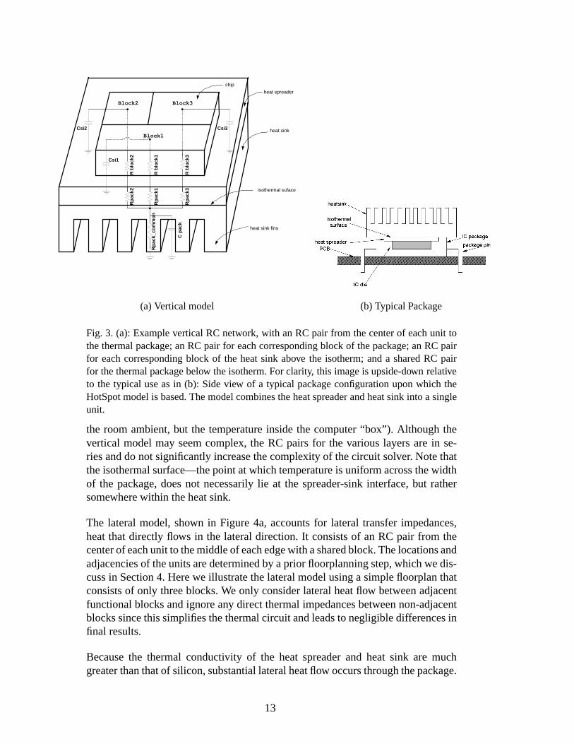
Fig. 3. (a): ExampleverticalRC network, with anRC pair from thecenterof eachunit tothethermalpackage;anRC pair for eachcorrespondingblock of thepackage;anRC pairfor eachcorrespondingblock of the heatsink above the isotherm;anda sharedRC pairfor thethermalpackagebelow theisotherm.For clarity, this imageis upside-down relativeto the typical useasin (b): Sideview of a typical packageconfigurationuponwhich theHotSpotmodelis based.Themodelcombinestheheatspreaderandheatsink into a singleunit.
the room ambient,but the temperatureinsidethe computer“box”). Although thevertical modelmay seemcomplex, the RC pairs for the variouslayersare in se-riesanddo notsignificantlyincreasethecomplexity of thecircuit solver. Notethattheisothermalsurface—thepointatwhichtemperatureis uniformacrossthewidthof the package,doesnot necessarilylie at the spreader-sink interface,but rathersomewherewithin theheatsink.
The lateralmodel,shown in Figure4a, accountsfor lateral transferimpedances,heatthat directly flows in the lateraldirection.It consistsof an RC pair from thecenterof eachunit to themiddleof eachedgewith asharedblock.Thelocationsandadjacenciesof theunitsaredeterminedby aprior floorplanningstep,whichwedis-cussin Section4. Herewe illustratethelateralmodelusinga simplefloorplanthatconsistsof only threeblocks.We only considerlateralheatflow betweenadjacentfunctionalblocksandignoreany directthermalimpedancesbetweennon-adjacentblockssincethissimplifiesthethermalcircuit andleadsto negligible differencesinfinal results.
Becausethe thermal conductivity of the heat spreaderand heat sink are muchgreaterthanthatof silicon,substantiallateralheatflow occursthroughthepackage.
13

R23 R32
R21 R31
R13R12
Block2 Block3
Block1
C12 C13
C23
(a) LateralModel
chip
heat spreader
heat sink
heat sink fins
R23 R32
R21 R31
R13R12
R b
lock
2
Csi2 Csi3
Csi1
R b
lock
1
R b
lock
3
Rp
ack2
Rp
ack1
Rp
ack3 isothermal suface
Block2 Block3
Block1
Rp
ack_
com
mo
n
C p
ack
C12C13
C23
(b) CompleteModel
Fig. 4. (a): Lateralmodel,with anRC pair betweenthecenterof eachnodeandthecenterof eachsharededge.(b):OverallRCmodel,includingbothverticalandlateralcomponents.
Ideally, thelateralmodelthereforehasthreelayers:onefor lateralheatflow in thesilicon;onefor lateralheatflow in thespreader(madeof aluminum,copper, siliconcarbide,or someorganicmaterial);andonefor lateralheatflow in the heatsink.Betweenthe die andspreaderlayers,andthe spreaderandsink layers,would beverticalresistancesto modelthenon-idealheatconductivity of theinterfacelayers(typically phase-changefilms, thermalgrease,etc.).Sincetheseinterfacelayersaresothin asto haveessentiallyno thermalmassandthey areasmallconstantscalingfactor, weaccountfor themin the � scalingfactorbelow.
Suchamulti-layermodelleadsto anRCmodelthatwouldbetoocomplex to solveat thesimulationratewedesireandmightrequiremoredetaileddesigninformationthatarchitectsmightnotpossess.Instead,wecollapsethethreelayersinto asinglelateral layer usinga scalingfactorderived from our referencemodel—seebelow.In thiswayweaccuratelycapturethelateralheatflow in all threelayersbasedonlyon architectural,area,andfloorplaninformationandthe packageinformationwecalculatebelow. Thecombinedmodelis shown in Figure4b.
The resultingmodelaccomplishesthe goal of a paramterizedmodel that canbederived in a straightforward fashionfrom the high-level specificationsthat archi-tectstypically work with, andavoids the needfor low-level simulationsor directphysicalmeasurementsthatthermalmulti-port techniquestypically require.
14
6 HotPackage: Accounting for Package Design
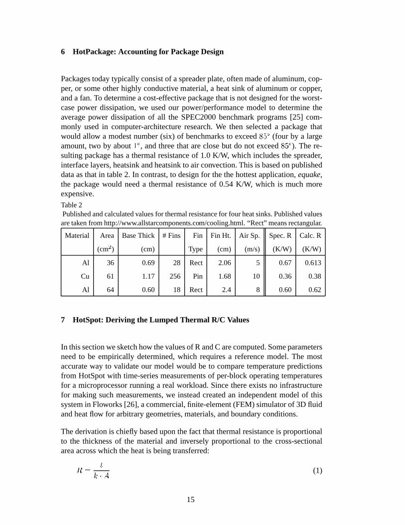
Packagestodaytypically consistof aspreaderplate,oftenmadeof aluminum,cop-per, or someotherhighly conductive material,a heatsink of aluminumor copper,anda fan.To determinea cost-effectivepackagethatis not designedfor theworst-casepower dissipation,we usedour power/performancemodel to determinetheaveragepower dissipationof all the SPEC2000benchmarkprograms[25] com-monly usedin computer-architectureresearch.We then selecteda packagethatwould allow a modestnumber(six) of benchmarksto exceed ��� (four by a largeamount,two by about �� , andthreethatareclosebut do not exceed ��� ). There-sultingpackagehasa thermalresistanceof 1.0 K/W, which includesthespreader,interfacelayers,heatsinkandheatsinkto air convection.This is basedonpublisheddataasthatin table2. In contrast,to designfor thethehottestapplication,equake,the packagewould needa thermalresistanceof 0.54 K/W, which is muchmoreexpensive.
Table2Publishedandcalculatedvaluesfor thermalresistancefor four heatsinks.Publishedvaluesaretakenfrom http://www.allstarcomponents.com/cooling.html. “Rect” meansrectangular.
Material Area BaseThick # Fins Fin Fin Ht. Air Sp. Spec.R Calc.R
(cm� ) (cm) Type (cm) (m/s) (K/W) (K/W)
Al 36 0.69 28 Rect 2.06 5 0.67 0.613
Cu 61 1.17 256 Pin 1.68 10 0.36 0.38
Al 64 0.60 18 Rect 2.4 8 0.60 0.62
7 HotSpot: Deriving the Lumped Thermal R/C Values
In thissectionwesketchhow thevaluesof R andC arecomputed.Someparametersneedto be empirically determined,which requiresa referencemodel.The mostaccurateway to validateour modelwould be to comparetemperaturepredictionsfrom HotSpotwith time-seriesmeasurementsof per-block operatingtemperaturesfor a microprocessorrunninga real workload.Sincethereexistsno infrastructurefor makingsuchmeasurements,we insteadcreatedan independentmodelof thissystemin Floworks[26], acommercial,finite-element(FEM) simulatorof 3D fluidandheatflow for arbitrarygeometries,materials,andboundaryconditions.
Thederivationis chieflybaseduponthefactthatthermalresistanceis proportionalto the thicknessof the materialand inverselyproportionalto the cross-sectionalareaacrosswhich theheatis beingtransferred:��� ������ (1)
15

where�
is the thermalconductivity, ���������� �"!for silicon at �� C. Thermal
capacitance,on theotherhand,is proportionalto boththicknessandarea:# �%$ � � ��� (2)
where$
is thethermalcapacitanceperunit volume, ��&('��*)+�,��-/."�� 10 �2! for siliconand 34&(���5)6�,��-�."�� 10 �7! for copper. Calibrationwith ourFloworksFEM simulationhasshown thata scalingfactoris necessaryfor thecapacitance(
$) values:0.47for
silicon and0.62for copper. In exploringdifferentconfigurations,wehavecometotheconclusionthatthis factoris partlydueto anaspect-ratioeffect,becausethedieespeciallyis extremelythin anddoesnotabsorbheatuniformly throughoutits vol-ume,andpartlyaconsequenceof thedifferencebetweenlumpedversusdistributedRC models[18].
For our1 K/W package,wemustdealwith thefactthattheisothermis notonthein-terfacebetweenthespreaderandsink.Thelocationof this isothermdependsonthethicknessof thechip.Usingour referencemodelin Floworks,wesimulatedavari-etyof packageconfigurationswith variousthicknessesfor thedieandspreader, andvariouspower-densityprofileson thechip, in orderto find the isothermalsurface.Wefoundaconsistentlinearrelationshipthatthefractionof thepackagethatis notisothermalis givenby 8 � �:9�� � �;� �=<?>A@CB , sofor a chip thickness� � �D&E�6)��,�FG mthat we use, 8 � �D&H��I . This meansthat 0.06 K/W mustbe sharedamongall theblocks(inverselyproportionalto theirarea),with theremaining0.94K/W in asin-gle common
�=<?>;@JB @JKMLNL.
For thelateralcomponents,RsandCsarecomputedfrom thecenterof eachblockto the centerof eachblock’s sharededge.The Rs andCs mustalsobe scaledtoaccountfor the collapsingof the threelayers,and to accountfor the impact ofaspectratio.Severalstepsarethereforerequired.
First,for eachblockthebulk resistance�PORQTSEBAU
is computedusingEquation(1).Thisis thenscaledby � � �4&E�4�, to accountfor the collapsingof the lateral layers. �is determinedby the thermalconductivity of the metalmaterialscomprisingthespreaderandsink, andthe muchlarger thicknessof the packagecomparedto thesilicon. It is foundempiricallyusingFloworks,asdescribedin [14]. Thevalueof� is independentof blocksize,aspectratio,chip/packagethickness,powerdensity,andtechnology. Finally,
�PORQTSEBAUis dividedinto individual resistancescorresponding
to thesharededgeswith neighboringblocks.
This assumesa squareblock. But the heatflow is also dependenton the aspectratio; as a block becomesnarrower, more heatflows acrossthe long edgethanacrosstheshortedge,requiringthe introductionof a scalingfactor V thatmodelsthis difference.Thuswe computetheR in eachdimension,W and X , to eachof thefour directions(up,down, left, right) as:
16

�ZY*�\[] V �^`_ a� b �:cedf�Tgh � �PORQTSiB;U� (3)
�Zjk�\[] V �^ _ � a b �:cedf�Tgh � �PORQTSiB;U� (4)
Here a is the W dimensionand � is the X dimension.If a � � , theentire V termcancelsand
�ZYl���mjn���PORQTSiB;U ��� . Empirically fitting to our FEM yields V � �4&o�:9 ,which is independentof block sizes,aspectratios,chip/packagethickness,powerdensity, andtechnology. After
�ZYand
�Zjarecalculated,they needto be further
subdividedif theblockhasmorethanoneneighborin eachof thefour directions.
Thismodelis boundary-andinitial-conditionindependentbyconstructionsincethecomponentvaluesarederived from materialphysicalandgeometricalvalues.Al-thoughthereareseveralempiricalfactorsusedin theformulas( 8 , � , V ), theirvaluesarethesame,independentof thedetailsof thechip andarchitecturebeingstudied,within the limits of currentstate-of-the-artprocesses.Becausethe HotBlocksRCnetwork is not obtainedfrom full solutionsof thetime-dependentheat-conductionequationfor every possiblearchitecture,theremay be boundaryand initial con-dition setsthat would lead to inaccurateresults.But for the rangeof reasonablearchitecturalfloorplansand the short time scalesof architecturesimulations,theparameterizedderivationof thechip modelensuresthat themodelis indeedBICIfor practicalpurposesif not in a formal sense.In otherwords,architectscanrelyon themodelto beindependentof boundaryandinitial conditionsfor purposesorarchitecturalsimulation.
A final noteregardsthetemperature-dependenceof conductivity. This temperaturedependenceonly affectsresultsfor relatively largetemperaturerangesgreaterthan��� [27]. Our currentchip model hasa much smaller rangein active mode,sowe usethethermalconductivity of silicon at �� , our specifiedmaximumjunctiontemperature.Incorporatingatemperaturedependencewill beanecessaryextensionto HotSpotfor workingwith largertemperatureranges.
8 Calibrating the Model
Dynamiccompactmodelsarewell establishedin thethermal-engineeringcommu-nity, but weareunawareof any thathavebeendevelopedto modeltemperaturein awaythatis compatiblewith typicalmicroarchitectureresearchtools.Of course,theexact compactmodelmustbe validatedto minimize errorsthat might arisefrommodelingheattransferusinglumpedelements.
Thisisdifficult, becausewearenotawareof any sourceof localized,time-dependentmeasurementsof physicaltemperaturesthatcouldbeusedto validateourmodel.It
17

remainsanopenproblemin thethermal-engineeringcommunityhow to obtainsuchdirectmeasurements.Eventually, wehopeto usethermaltestchips(e.g.,[28]), andpossiblyalsoa systemlike an infraredcameraor IBM’ s PICA picosecondimag-ing tool [29] with real superscalarprocessorsto imageheatdissipationon a finetemporalandspatialgranularity. Until this becomesfeasible,we areusinga ther-modynamicsandcomputationalfluid-dynamicstool asa semi-independentmodelwhichwecanusefor validationandcalibration.As mentionedearlier, weareusingFloworks[26], acommercial,finite-elementsimulatorof 3D fluid andheatflow forarbitrarygeometries,materials,andboundaryconditions.
Floworks andHotSpotareonly semi-independent,becausesomeof the HotSpotparameterswere calibratedindependentlyusing Floworks. Nevertheless,we canverify thatthetwo obtainsimilar steady-stateoperatingtemperaturesandtransientresponse.
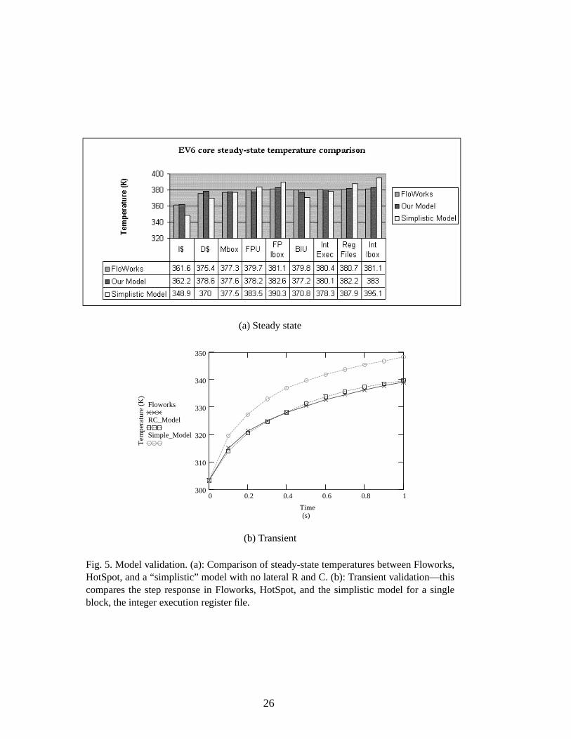
Figure5ashows steadystatevalidationcomparingtemperaturespredictedby Flo-works,HotSpot,anda “simplistic” modelthateliminatesthelateralportionof theRC circuit (but not the package)to show the importanceof transferimpedancesevenfor architecturestudies.HotSpotshows goodagreementwith Floworks,witherrorsp alwayslessthan5.6%andusuallylessthan2.5%.Thesimplisticmodel,ontheotherhand,hasmuchlargererrors,ashigh as29%,plushasthedrawbackthatthedeviationsareneitherconsistentlyhighor low. Oneof thelargesterrorsis for thehottestblock,which meanstoo many thermaltriggerswill begenerated.Figure5bshows transientvalidationcomparing,for FloworksandHotSpot,theevolution oftemperaturein oneblockonthechipovertime.Theagreementis excellentbetweenFloworksandHotSpot,but thesimplisticmodelshowstemperaturerisingmuchtoofast.Theagreementwouldbeevenworsehadweomittedthepackagemodel.
Becausethemodelis deriveddirectly from theprocessor’sfloorplanandbasicma-terialpropertiesof its package,it is easilyaddedto any architecturalsimulator. Thismodelis a portablemodulethatis now publicly availableon theweb.
Dueto thelack of anarchitecturaltemperaturemodel,a few prior studieshave at-temptedto modeltemperaturesby averagingpower dissipationover a window oftime. This will not captureany localizedheatingunlessit is doneat thegranular-ity of on-chipblocks,but even thenit fails to accountfor lateralcouplingamongblocks,theroleof theheatsink,etc.Wehavealsoencounteredthefallacy thattem-peraturecorrespondsto instantaneouspower dissipation.This is clearly not true;thethermalcapacitanceactsasa low-passfilter in translatingpowervariationsintotemperaturevariations.
To show the importanceof usinga thermalmodel insteadof a power metric, wehavecomputedthecorrelationcoefficientbetweentemperatureandthemoving av-erageof power dissipation.The datain Table 3 comefrom the gcc benchmark,
p Percenterrorin temperatureis computedwith respectto theambient,qsr C or t�u?v K.
18

(a)Steadystate
0 0.2 0.4 0.6 0.8 1300
310
320
330
340
350
(s)
Tem
pera
ture
(K
)
Floworks
RC_Model
Simple_Model
Time
(b) Transient
Fig. 5. Model validation.(a): Comparisonof steady-statetemperaturesbetweenFloworks,HotSpot,anda “simplistic” modelwith no lateralR andC. (b): Transientvalidation—thiscomparesthe stepresponsein Floworks, HotSpot,and the simplistic model for a singleblock, theintegerexecutionregisterfile.
which is representativeof all of thebenchmarkswhichweexamined.TemperatureswerecollectedusingHotSpot,andpower measurementswerecollectedusinganaveragingperiodof onemillion cycles,bothfor a simulationof onebillion cycles.R-squaredvaluesfor the correlationarereportedin Table3 alongwith the units’meanpowerandtemperaturesoverthesimulation,andthepercentof timetheunitsspendin thermalviolation. The R-squaredvaluegivesthe percentageof variancethat is commonbetweentwo setsof data:correlationis very poor for mostunits,especiallythehotones.
19

Table3Correlationof power andtemperaturefor gcc.
Units Temp Power R-Square % cycles
( C) (W) (%) in thermal
violation
I-Cache 78.3 4.53 16 0
BPred 78.2 1.94 26 0
ITB 79.1 0.21 24 0
IntExec 81.7 3.85 30 33
IntReg 83.2 2.97 20 60
IntQ 78.1 0.20 15 0
IntMap 76.3 0.58 08 0
LdStQ 79.7 1.84 16 0
D-Cache 83.1 8.44 15 57
DTB 79.1 0.11 06 0
FPMap 73.6 0.03 02 0
FPAdd 76.1 0.37 79 0
FPQ 77.0 0.01 78 0
FPMul 74.5 0.39 65 0
FPReg 75.4 0.23 51 0
L2 68.7 0.94 01 0
9 Conclusions and Future Work
This paperdescribesan approachto modelingthermalbehavior in architecture-level power/performancesimulators.It is basedonasimplenetwork of thermalre-sistancesandcapacitances,whicharederivedusingareaandfloorplaninformationfor the major functionalblocksat the architecturelevel, andestimatesof thermalresistanceandcapacitancefor themicroprocessor’s thermalpackage.We describetechniquesfor automatingthe derivation of area,floorplan,package,andthermalR/C information to minimize the effort requiredof the processorarchitect.Areaandfloorplaninformationandthe resultingthermalmodelmustbe derived usinghigh-level estimationbecausearchitecture-level studiesareoftenconductedbeforecreatingthelower-level processordescriptionsthatareneededby traditionalalgo-rithms.Packageinformationcanbederivedusingwell-knownmethodsfor comput-ing thermalresistanceandcapacitancefor heatspreaders,heatsinks,convection,etc.
20

Early work using a simpler versionof our model [4] showed the importanceofmodelingheatat finer granularitiesthanthewholedie, which is theapproachthatearlierwork in the processor-architecturecommunityhad taken. This paperalsoshows the importanceof modelingtransferor “lateral” thermalimpedances.Thethermalmodelwhich weproposehere(HotSpot)thereforefills a void in thearchi-tecturecommunity’smodelingcapabilities.It canbeusedto simulatehow thermalstressis correlatedto thearchitecture,how designdecisionsinfluencethermalbe-havior andotherimportanteffectsthataredependentonoperatingtemperaturelikeleakagecurrents(for example,in conjuctionwith temperature-awareleakagemod-els [30]), andfor designof architecturalruntimethermalmanagement.HotSpotisavailableon thewebat http://lava.cs.virginia.edu/hotspot.
Futurework consistsof developingmodelsfor sensoraccuracy anddelay(neededfor realisticmodelingof run-timethermalmanagement)andmorethoroughvali-dationof themodelusingphysicalmeasurements,eithervia testchipsor thermal-imaging techniques.Another interestingavenuefor future work is to find waysto adaptthe morerigoroustechniquesof direct constructionof dynamiccompactmodelsfrom numericalor analyticalthermalmodelsto describethe3D heatflowwith lessapproximationbut in waysthatarecompatiblewith early-stage,high-levelarchitecturestudies.
It is ourhopethatthiswork will stimulategreatercollaborationamongthepackage,VLSI, andarchitecturecommunitiesto find betterwaysto manageheatatall levelsof computersystemsdesign.
Acknowledgments
Wewouldliketo thankPradipBose,David Brooks,GeorgeCai,HowardDavidson,EdGrochowski,andMargaretMartonosifor theirhelpfulcomments.WealsothankAmar Dwarka,Yingmin Li, Yong Ma, Amit Naidu,DharmeshParikh, Paolo Re,GarrettRose,Ram Suryanarayan,Hao Zhang,Yan Zhangand David Tarjan fortheir contributions to this work. This work is supportedin part by the NationalScienceFoundationundergrantsCCR-0133634,MIP-9703440,a grantfrom IntelMRL, andanExcellenceAwardfrom theUniv. of Virginia Fundfor ExcellenceinScienceandTechnology.
References
[1] D. Brooks, M. Martonosi, Dynamic thermal managementfor high-performancemicroprocessors,in: Proceedingsof the SeventhInternationalSymposiumon High-PerformanceComputerArchitecture,2001,pp.171–82.
21

[2] W. Huang, J. Renau,S.-M. Yoo, J. Torellas, A framework for dynamic energyefficiency and temperaturemanagement,in: Proceedingsof the 33rd AnnualIEEE/ACM InternationalSymposiumon Microarchitecture,2000,pp.202–13.
[3] E. Rohou,M. Smith, Dynamically managingprocessortemperatureand power, in:Proceedingsof the2ndWorkshopon Feedback-DirectedOptimization,1999.
[4] K. Skadron,T. Abdelzaher, M. R. Stan,Control-theoretictechniquesandthermal-RCmodelingfor accurateand localizeddynamicthermalmanagement,in: Proceedingsof theEighthInternationalSymposiumonHigh-PerformanceComputerArchitecture,2002,pp.17–28.
[5] W. Batty, et al., Global coupledEM-electrical-thermalsimulationandexperimentalvalidation for a spatial power combining MMIC array, IEEE TransactionsonMicrowave TheoryandTechniques(2002)2820–33.
[6] G. Digele, S. Lindenkreuz, E. Kaspar, Fully coupled dynamic electro-thermalsimulation,IEEE Transactionson Very LargeScaleIntegration(VLSI) Systems5 (3)(1997)250–57.
[7] V. Koval, I. W. Farmaga,MONSTR: A completethermal simulator of electronicsystems,in: Proceedingsof the31stDesignAutomationConference,1994.
[8] S.S.Lee,D. J.Allstot, Electrothermalsimulationof integratedcircuits,IEEEJournalof Solid-StateCircuits28 (12) (1993)1283–93.
[9] M. N. Sabry, A. Bontemps,V. Aubert,R. Vahrmann,Realisticandefficientsimulationof electro-thermaleffects in VLSI circuits, IEEE Transactionson Very Large ScaleIntegration(VLSI) Systems5 (3) (1997)283–89.
[10] V. Szekely, A. Poppe,A. Pahi,A. Csendes,G.Hajas,Electro-thermalandlogi-thermalsimulationof VLSI designs,IEEE Transactionson VLSI Systems5 (3) (1997)258–69.
[11] K. Torki, F. Ciontu, IC thermal map from digital and thermal simulations, in:Proceedingsof the2002InternationalWorkshopon THERMal Investigationsof ICsandSystems(THERMINIC), 2002,pp.303–08.
[12] S. Gunther, F. Binns,D. M. Carmean,J. C. Hall, Managingthe impactof increasingmicroprocessorpowerconsumption,in: Intel TechnologyJournal,2001.
[13] D. Brooks, V. Tiwari, M. Martonosi,Wattch: A framework for architectural-levelpower analysisandoptimizations,in: Proceedingsof the 27th Annual InternationalSymposiumonComputerArchitecture,2000,pp.83–94.
[14] M.-N. Sabry, Dynamiccompactthermalmodels:An overview of currentandpotentialadvances,in: Proceedingsof the8th Int’ l Workshopon THERMal INvestigationsofICs andSystems,2002,invited paper.
[15] A. Krum, Thermalmanagement,in: F. Kreith (Ed.), The CRC handbookof thermalengineering,CRCPress,BocaRaton,FL, 2000,pp.2.1–2.92.
22

[16] P. Shivakumar, N. P. Jouppi,Cacti 3.0: An integratedcachetiming, power andareamodel,Tech.rep.,CompaqWesternResearchLaboratory(Feb. 2001).
[17] J.M. Mulder, N. T. Quach,M. J.Flynn,An areamodelfor on-chipmemoriesanditsapplication,IEEEJournalof Solid-StateCircuits26 (2) (1991)98–106.
[18] J. M. Rabaey, Digital Integrated Circuits: A Design Perspective, Prentice-Hall,EnglewoodCliffs, NJ,1995.
[19] M. Nemani,F. N. Najm,High-level areaandpowerestimationfor VLSI circuits,IEEETransactionson Computer-Aided Designof IntegratedCircuits andSystems18 (6)(1999)697–713.
[20] D. F. Wong,D. L. Liu, A new algorithmfor floorplandesign,in: Proccedingsof theDesignAutomationConference,1986,pp.101–107.
[21] MIPS R10000 die photo, from website: CPU Info Center,http://bwrc.eecs.berkeley.edu/CIC/die photos/#mips.
[22] Intel Pentium die photo, from website: CPU Info Center,http://bwrc.eecs.berkeley.edu/CIC/die photos/pentium.gif.
[23] M. Matson, et al., Circuit implementation of a 600MHZ superscalarRISCmicroprocessor, ComputerDesign:VLSI in ComputersandProcessors26 (2) (1998)104–110.
[24] R. Mahajan, Thermal managementof CPUs: A perspective on trends, needsand opportunities,keynote presentationat the 8th Int’ l Workshop on THERMalINvestigationsof ICs andSystems(Oct.2002).
[25] Standard Performance Evaluation Corporation, SPEC CPU2000 Benchmarks,http://www.specbench.org/osg/cpu2000.
[26] Floworks: Fluid Flow Analysis for SolidWorks, NIKA GmbH. Website,http://www.floworks.com.
[27] M. Rencz,V. Szekely, Studieson the error resulting from neglecting nonlinearityeffects in dynamic compact model generation,in: Proceedingsof the 8th Int’ lWorkshoponTHERMal INvestigationsof ICs andSystems,2002,pp.10–16.
[28] Z. Benedek,B. Courtois,G.Farkas,E.Kollar, S.Mir, A. Poppe,M. Rencz,V. Szekely,K. Torki, A scalablemulti-functionalthermaltestchip family: Designandevaluation,Transactionsof theASME, Journalof ElectronicPackaging123(4) (2001)323–30.
[29] M. McManus,S.Kasapi,PICA watcheschipswork, OptoelectronicsWorld .
[30] D. Parikh,Y. Zhang,K. Sankaranarayanan,K. Skadron,M. Stan,Comparisonof state-preservingvs. non-statepreservingleakagecontrol in caches,in: Proceedingsof the2003Workshopon Duplicating,Deconstructing,andDebunking,2003.
23

Fig. 1. The semicircularfloorplan generatedby the HotFloorplantool using the MIPSR10000configuration.
Fig. 2. “Normalized” floorplan for the MIPS R10000(left), Intel Pentium(middle), andAlpha21264(right) processors.
24

chip
heat spreader
heat sink
heat sink fins
R b
lock
2Csi2 Csi3
Csi1R
blo
ck1
R b
lock
3
Rp
ack2
Rp
ack1
Rp
ack3 isothermal suface
Block2 Block3
Block1
Rp
ack_
com
mo
n
C p
ack
(a) Verticalmodel (b) TypicalPackage
Fig. 3. (a): ExampleverticalRC network, with anRC pair from thecenterof eachunit tothethermalpackage;anRC pair for eachcorrespondingblock of thepackage;anRC pairfor eachcorrespondingblock of the heatsink above the isotherm;anda sharedRC pairfor thethermalpackagebelow theisotherm.For clarity, this imageis upside-down relativeto the typical useasin (b): Sideview of a typical packageconfigurationuponwhich theHotSpotmodelis based.Themodelcombinestheheatspreaderandheatsink into a singleunit.
R23 R32
R21 R31
R13R12
Block2 Block3
Block1
C12 C13
C23
(a) LateralModel
chip
heat spreader
heat sink
heat sink fins
R23 R32
R21 R31
R13R12
R b
lock
2
Csi2 Csi3
Csi1
R b
lock
1
R b
lock
3
Rp
ack2
Rp
ack1
Rp
ack3 isothermal suface
Block2 Block3
Block1
Rp
ack_
com
mo
n
C p
ack
C12C13
C23
(b) CompleteModel
Fig. 4. (a): Lateralmodel,with anRC pair betweenthecenterof eachnodeandthecenterof eachsharededge.(b):OverallRCmodel,includingbothverticalandlateralcomponents.
25
(a)Steadystate
0 0.2 0.4 0.6 0.8 1300
310
320
330
340
350
(s)
Tem
pera
ture
(K
)
Floworks
RC_Model
Simple_Model
Time
(b) Transient
Fig. 5. Model validation.(a): Comparisonof steady-statetemperaturesbetweenFloworks,HotSpot,anda “simplistic” modelwith no lateralR andC. (b): Transientvalidation—thiscomparesthe stepresponsein Floworks, HotSpot,and the simplistic model for a singleblock, theintegerexecutionregisterfile.
26

Table1Distancesfrom computedvs.observedlocationsof themajorfunctionalblocks.Resultsarein percent,normalizedto theheightof thechip.
Alpha MIPS Pentium
I-cache 6.4% 5.4% 11.1%
D-cache 3.9% 10.8% 9.1%
Integerexecution NA 36.8% 24.8%
FPexecution 71.2% 49.1% 5.6%
Queues NA 50.8% 21.7%
Branchpred. 4.4% 7.9% 52.3%
Decode/rename 37.9% 22.7% 7.1%
Table2Publishedandcalculatedvaluesfor thermalresistancefor four heatsinks.Publishedvaluesaretakenfrom http://www.allstarcomponents.com/cooling.html. “Rect” meansrectangular.
Material Area BaseThick # Fins Fin Fin Ht. Air Sp. Spec.R Calc.R
(cm� ) (cm) Type (cm) (m/s) (K/W) (K/W)
Al 36 0.69 28 Rect 2.06 5 0.67 0.613
Cu 61 1.17 256 Pin 1.68 10 0.36 0.38
Al 64 0.60 18 Rect 2.4 8 0.60 0.62
27

Table3Correlationof power andtemperaturefor gcc.
Units Temp Power R-Square % cycles
( C) (W) (%) in thermal
violation
I-Cache 78.3 4.53 16 0
BPred 78.2 1.94 26 0
ITB 79.1 0.21 24 0
IntExec 81.7 3.85 30 33
IntReg 83.2 2.97 20 60
IntQ 78.1 0.20 15 0
IntMap 76.3 0.58 08 0
LdStQ 79.7 1.84 16 0
D-Cache 83.1 8.44 15 57
DTB 79.1 0.11 06 0
FPMap 73.6 0.03 02 0
FPAdd 76.1 0.37 79 0
FPQ 77.0 0.01 78 0
FPMul 74.5 0.39 65 0
FPReg 75.4 0.23 51 0
L2 68.7 0.94 01 0
28