how to design 3d origami + other stuff - duke universityoutline • a primer to scaffolded dna...
TRANSCRIPT

HowtoDesign3DOrigami+otherstuff

Outline
• AprimertoscaffoldedDNAorigami– Design– Methods
• CaDNAno/CandoTutorial
Whatwealreadycovered
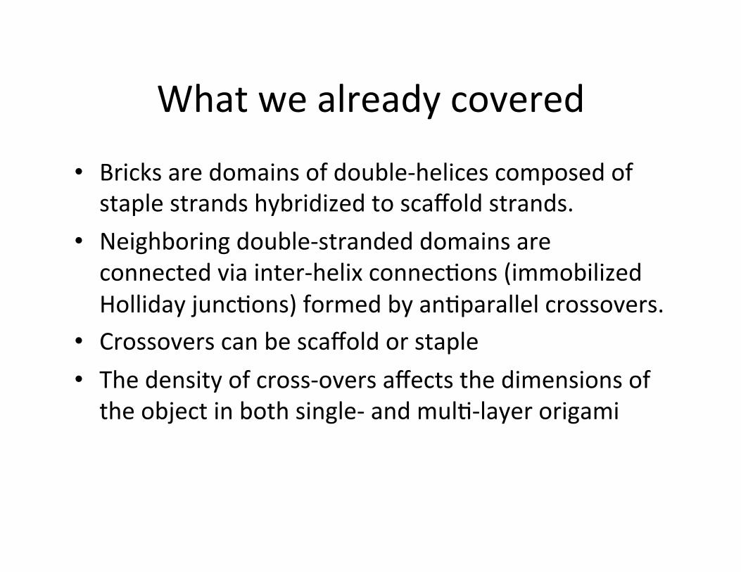
• Bricksaredomainsofdouble-helicescomposedofstaplestrandshybridizedtoscaffoldstrands.
• Neighboringdouble-strandeddomainsareconnectedviainter-helixconnecJons(immobilizedHollidayjuncJons)formedbyanJparallelcrossovers.
• Crossoverscanbescaffoldorstaple• Thedensityofcross-oversaffectsthedimensionsoftheobjectinbothsingle-andmulJ-layerorigami

Sometrickswe’veseen
• single-strandedscaffoldsegments– entropicspringsintensegritystructures(thinkofDNApolymerasloosespring).hPp://scienJficcuriosity.blogspot.com/2007/12/on-rubber-bands-entropic-springs-and.html
• SeeShihetal,Self-assemblyof3DprestressedtensegritystructuresfromDNA.
• prevenJngunwantedbase-stackinginteracJonsatinterfaces(loopsatinterfaces)
• single-strandedscaffold/staplecanserveasanchors(nanobreadboard).
Square,HexorHoneycomb?
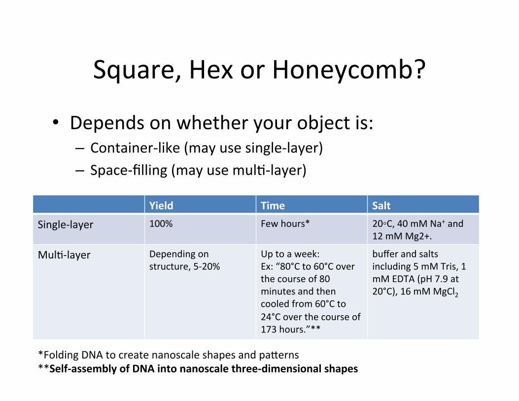
• Dependsonwhetheryourobjectis:– Container-like(mayusesingle-layer)– Space-filling(mayusemulJ-layer)
Yield Time Salt
Single-layer 100% Fewhours* 20◦C,40mMNa+and12mMMg2+.
MulJ-layer Dependingonstructure,5-20%
Uptoaweek:Ex:“80°Cto60°Coverthecourseof80minutesandthencooledfrom60°Cto24°Coverthecourseof173hours.”**
bufferandsaltsincluding5mMTris,1mMEDTA(pH7.9at20°C),16mMMgCl2
*FoldingDNAtocreatenanoscaleshapesandpaPerns**Self-assemblyofDNAintonanoscalethree-dimensionalshapes

Square,HexorHoneycomb?
• Single-layer(2Dor3Dcontainer):– Square(nomenJonofhoneycomborhex)?
• MulJ-layer(3Dspace-filling):– Canusesquareorhoneycomb(orhex,dependingonyourneeds)
– What’sthedifference?
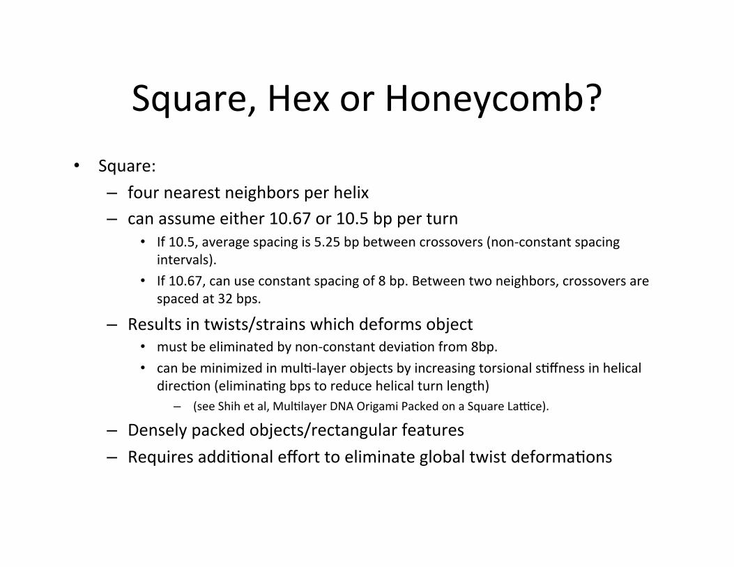
Square,HexorHoneycomb?• Square:
– fournearestneighborsperhelix– canassumeeither10.67or10.5bpperturn
• If10.5,averagespacingis5.25bpbetweencrossovers(non-constantspacingintervals).
• If10.67,canuseconstantspacingof8bp.Betweentwoneighbors,crossoversarespacedat32bps.
– Resultsintwists/strainswhichdeformsobject• mustbeeliminatedbynon-constantdeviaJonfrom8bp.• canbeminimizedinmulJ-layerobjectsbyincreasingtorsionalsJffnessinhelical
direcJon(eliminaJngbpstoreducehelicalturnlength)– (seeShihetal,MulJlayerDNAOrigamiPackedonaSquareLalce).
– Denselypackedobjects/rectangularfeatures– RequiresaddiJonalefforttoeliminateglobaltwistdeformaJons


Square,HexorHoneycomb?• Honeycomblalce:
ToconstrainDNAdouble-helixdomainstothislalceconfiguraJon,youneedtofollowtheserules:– assumes10.5bpperfullturn.– eachhelixhas3nearestneighbors– crossoversat7bp,or240*-->5'->3':noon,8pm(240*),4am,noon.
• deviaJonscauselocalunder/overtwists+axialstrain.Targetedremoval/addiJonofbpcancauseglobaltwists/bendingthatcanbetuned.
– (seeShihetal,FoldingDNAintotwistedandcurvednanoscaleshapes).– placecross-oversbetweenaparJcularpairevery21bases,andsinceyouhave3neighbors,allcrossoverscanbespacedoutat7bpforeachneighbor.
– createsmoreporousstructures– noneedtoeliminatetwists(withrespecttocrossovers)

multilayer honeycomb lattice objects8. The effective width of a square lattice object along the vertical or horizontal cross-sectional axis (Fig. 3a) can be estimated as 2H + (H – 1)g in which H is the number of 2-nm-wide double-helical domains along that axis and g is the interhe-lical gap size in nanometers between cross-overs along the same axis1. The effective contribution of a single double-helical domain to the cross-sectional dimensions of multilayer honeycomb lattice objects has been found to range from 2.1 nm to 2.4 nm (refs. 7,8).
Computer-aided engineering for DNA origamiComputational tools for predicting 3D structure of DNA origami designs before initiating cost-intensive staple oligonucleotide synthesis are currently lacking. Such tools would be of particu-lar value in designing complex objects that incorporate curved and twisted elements. To this end we developed the computa-tional tool named computer-aided engineering for DNA ori-gami (CanDo) that uses the finite element method to compute 3D DNA origami shapes based on caDNAno design files (Fig. 4). CanDo models base pairs as two-node beam finite elements that represent an elastic rod with effective geometric (length of 0.34 nm and diameter of 2.25 nm; ref. 8) and material (stretch modulus of 1,100 pN, bend modulus of 230 pN nm2 and twist modulus of 460 pN nm; refs. 2,39) parameters. Sequence details are neglected at present, and users may specify custom geomet-ric and mechanical parameters for double-helical DNA domains. Each finite element node has three translational degrees of freedom for the center position of the cross-section and three rotational degrees of freedom for the orientation of the cross-section in torsion and bending40. Strand cross-overs defined in the caDNAno design file are modeled as rigid constraints that connect end nodes of base pairs that are coupled by interhelical cross-overs. To compute the 3D structure, CanDo first creates an initial configuration in which all double helices defined in the caDNAno source file are arranged linearly in space. This initial configuration is identical to the structure shown in one of the three design panels in caDNAno. CanDo then applies external forces to deform adjacent helices so that rigid cross-overs may be placed between helices based on the connectivity defined in the caDNAno design file. Subsequent release of these external forces followed by structural relaxation using nonlinear finite element analysis leads to deformation and internal strain when-ever the connectivity imposed by cross-overs is not compatible with the default geometry of B-form DNA. CanDo performs the numerical analysis using the commercially available finite ele-ment analysis software ADINA (automatic, dynamic, incremen-tal linear analysis; Adina R&D). More information about CanDo is available in Supplementary Note 2.
caDNAno design files may be submitted for analysis at (http://cando.dna-origami.org/). Users obtain the deformed shape of the relaxed structure as well as heatmaps of the local magnitude of thermally induced fluctuations, which indicate flexibility of the deformed structure. All output is provided in the .bild data format, which can be visualized using freely available 3D viewers such as University of California San Francisco Chimera41 (http://www.cgl.ucsf.edu/chimera/).
CanDo currently does not model interhelical electrostatic repulsion and neglects major and minor groove details. We will address these features and the capability to model wireframe or tensegrity-like structures in a future version that is currently
Single-layer square lattice DNA origami objects with a constant spacing of 16 bp between cross-overs to neighboring double-helical domains likely adopt a twisted shape in solution. Adhesion inter-actions with surfaces may abolish the twist deformations resulting in objects that lay flat on a surface. For single-layer DNA origami objects twist deformations appear to vanish when surface deposition is achieved by electrostatic immobilization1,31.
Thus, the square lattice packing rule allows for creating densely packed objects with rectangular features but may require additional effort to eliminate potentially undesired global twist deformations. The honeycomb lattice packing rule by default creates straight albeit more porous structures.
In a DNA origami object both staple and scaffold strands can contribute cross-overs for connecting double-helical domains. To accommodate both scaffold and staple cross-overs one can define two cross-over reference frames that are shifted in the helical direction by 5 bp or 6 bp (corresponding to a backbone rotation of ~180°). This approach neglects the major and minor groove in B-form DNA but appears not to cause global shape deforma-tions for multilayer objects with sufficient thickness ( 3 layers) or cross-sectional aspect ratio close to 1. For thinner objects it may be critical to keep track of major and minor groove phos-phate position to avoid unwanted rolling up38. An alternative is to work with high densities of staple cross-overs and avoid scaf-fold cross-overs as much as possible.
Finally, to estimate the dimensions of a DNA origami object one may use the following rules of thumb. The length of double-helical domains may be estimated via N 0.34 nm in which N indicates the number of base pairs in the double-helical domain. The value of 0.34 nm per bp holds true for single-layer square lattice1 and for
a
b7 bp
240°
Figure 3 | Packing and cross-over spacing rules for multilayer DNA origami. (a) Cross-sectional view of multilayer DNA origami objects in square lattice (left) and honeycomb lattice (right) packing. (b) Cross-overs in multilayer objects with honeycomb lattice packing, spaced in constant intervals of 7 bp along the helical axis to link double-helical domains to each of three possible neighbors. The cross-over spacing of 7 bp complies with the natural B-form DNA twist density of 10.5 bp per turn, which corresponds to an average backbone rotation of 240° for a given strand in a DNA double-helical domain.
224 | VOL.8 NO.3 | MARCH 2011 | NATURE METHODS
PERSPECTIVE
Square,HexorHoneycomb?
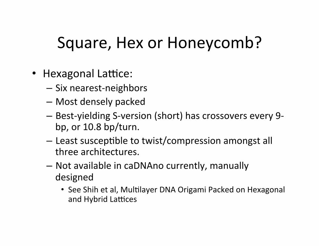
• HexagonalLalce:– Sixnearest-neighbors– Mostdenselypacked– Best-yieldingS-version(short)hascrossoversevery9-bp,or10.8bp/turn.
– LeastsuscepJbletotwist/compressionamongstallthreearchitectures.
– NotavailableincaDNAnocurrently,manuallydesigned
• SeeShihetal,MulJlayerDNAOrigamiPackedonHexagonalandHybridLalces
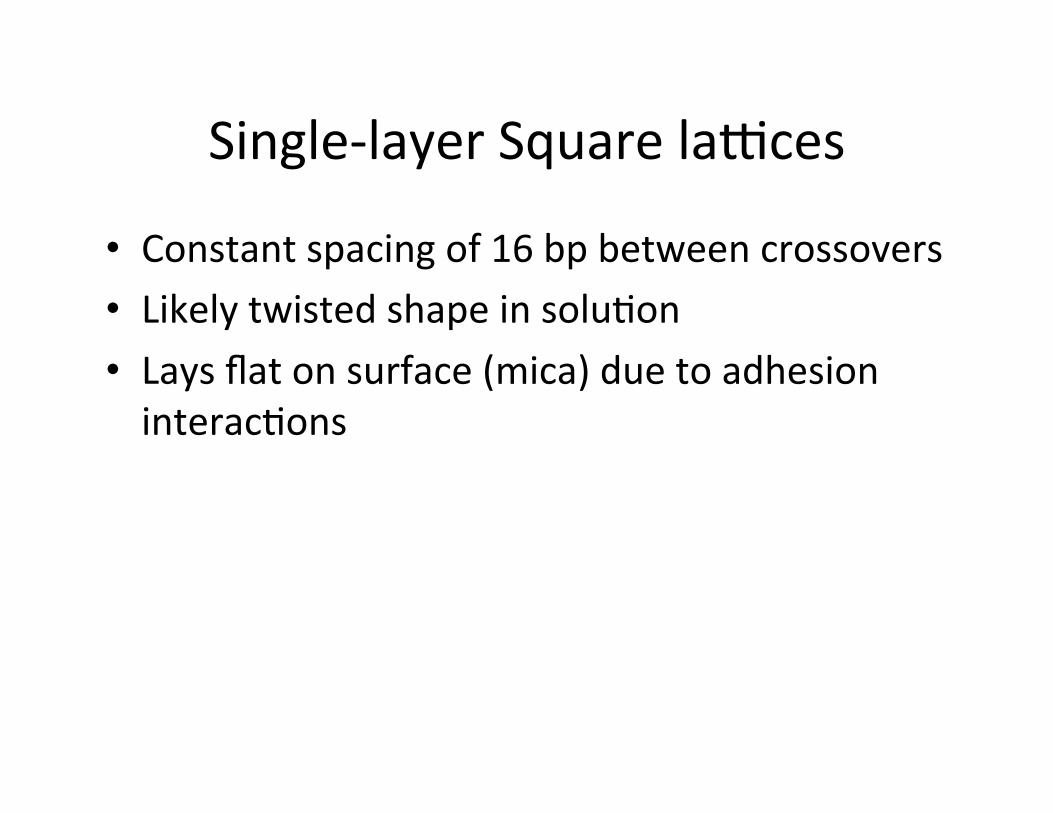
Single-layerSquarelalces
• Constantspacingof16bpbetweencrossovers• LikelytwistedshapeinsoluJon• Laysflatonsurface(mica)duetoadhesioninteracJons

Cross-overs,again
• Bothstapleandscaffoldstrandscontributecrossovers,however:– Forthickerobjects(>2layers),avoidglobalshapedeformaJonbyusing2referenceframes(forstaplevs.scaffoldcrossovers)
• Shiped5-6bps• Neglectsmajor/minorgroovesinB-DNA
– Forthinnerobjects,mightneedtokeeptrackofmajor/minorgroovestoavoidrollingupinthedirecJonperpendiculartothedsDNAaxis.
• SeeRothemundetal,DesignandCharacterizaJonofProgrammableDNANanotubes
• AlternaJve:usehighdensi*esofstaplecross-oversandavoidscaffoldcross-oversasmuchaspossible.
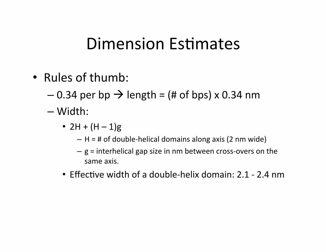
DimensionEsJmates
• Rulesofthumb:– 0.34perbpàlength=(#ofbps)x0.34nm– Width:
• 2H+(H–1)g– H=#ofdouble-helicaldomainsalongaxis(2nmwide)– g=interhelicalgapsizeinnmbetweencross-oversonthesameaxis.
• EffecJvewidthofadouble-helixdomain:2.1-2.4nm

CanDomodel
• Finiteelementmethodtocompute3DDNAorigamishapes.
• Modelsbpsas2-nodebeamfiniteelements,represenJngelasJcrodwithgeometricandmaterialparameters.– Defaults:
• Length:0.34nm• Diameter:2.25nm• Stretchmodulus:1,100pN• Bendmodulusof230pNnm2
• Twistmodulusof460pNnm

CanDoresult
• Deformedshapeofrelaxedstructure• HeatmapsoflocalmagnitudeofthermallyinducedfluctuaJons(flexibility)

CanDolimitaJons
• Sequencedetailsneglected• DoesnotmodelinterhelicalelectrostaJcrepulsion
• Neglectsmajor/minorgroovedetails.• Doesnotmodeltensegrity-likestructures
Origamiobjectstability
• Doorigamiobjectsremainfolded?– Heat– SoluJoncondiJons– Nucleases

Designsteps
1. Conceivetargetshape2. Designlayout,evaluatedesignanddetermine
staplesequences3. PreparescaffoldDNA/synthesizestapes4. PoolsubsetsofconcentraJon-normalized
oligonucleoJdes5. Runmolecularself-assemblyreacJons6. Analyzefoldingquality/purifyobjects7. Single-parJclebasedstructuralanalysis
1.Conceivetargetshape
SingleormulJ-layer?Squareorhoneycomb(orhexorhybrid?)Candivideintomodulesanddesign.
2.Designlayout,evaluatedesignanddeterminestaplesequences
“InpracJce,mulJplescaffold-staplelayoutsmayhavetobemadeforthesametargetobjecttoidenJfyasoluJonthatyieldswell-foldedobjects.”àTrialanderror• Mightrequiresite-directedaPachmentsorfluorescentdyes.

3.PreparescaffoldDNA/synthesizestapes
• ThequalityoffoldingofDNAorigamiobjectsmaydependon:– thescaffoldsequenceand– theparJcularcyclicpermutaJonusedinthedesign.
• PreparingsinglestrandedDNAthrough:– SupplementaryProtocolI:growingphage+purificaJon– EnzymaJcdigesJonofastrand– CanusedsDNA
• “DNAorigamiobjectsareassembledwith,ontheaverage,40-nucleoJde-longstaplemolecules;individualstaplesmayrangeinlengthfrom18nucleoJdesto50nucleoJdes”

4.PoolsubsetsofconcentraJon-normalizedoligonucleoJdes
“EqualamountsofconcentraJon-normalizedstapleoligonucleoJdesbelongingtoastructuralmodulearemixedtoformacommonpool.“

5.Runmolecularself-assemblyreacJons
“ThegoaloftheassemblyreacJonistoreachaminimumenergystateatcondiJonswheretheminimumcorrespondstothetargetstructure.”• Single-layerobjectsself-assemblefasterthanmulJlayerobjects.• TheassemblyofmulJlayerobjectscanproceedalongamulJtudeofpathways
thatmaynotnecessarilyleadtothefullyfoldedtargetstructurebuttoparJallyfoldeddeadends(kineJctraps)inwhichpartsofthestructureneedtodissolvebeforeassemblycanproceed.
• Single-layerobjectscanbeassembledbybrieflyheaJngthemixtureofscaffoldandstaplesto80°C,followedbyannealingatroomtemperatureduringafewhours.
• MulJlayerstructureshavebeenobservedtorequireannealingoverseveraldays.• IsothermalchemicaldenaturaJonandrenaturaJonisanalternaJvetothermal
annealing(formamide).• FoldingDNAorigamiobjectsbysequenJaladdiJonofstaplestoscaffoldorby
tuningthestaplelengthorsequencecomposiJonremainunexploredmethodsbywhichtheusermaydirectthesystemalongassemblypathwaysdevoidofsubstanJalkineJcfoldingtraps.
5.Runmolecularself-assemblyreacJons
AfoldingreacJoncontains:1)scaffoldDNA2)stapleDNA3)water4)pH-stabilizingbuffer5)addiJonalions.
• ScaffoldandstapleDNAaretypicallyaddedsuchthateachstapleispresentinadefinedstoichiometryrelaJvetothescaffoldinfive-totenfoldexcessàExactstoichiometriesseemnottomaPer.
• Scaffoldstrandsneednotbepurified• Differentstaple-scaffoldstoichiometriesmayneedtobetested.• YieldofassemblyofmulJlayerobjectsissensiJvetoMgCl2concentraJon.AdetailedprotocolforselngupfoldingreacJonsisavailableinSupplementaryProtocol2.

6.Analyzefoldingquality/purifyobjects
• AnalysisofthequalityoffoldingofDNAorigamiobjectsandpurificaJonofadesiredspeciescanbeaccomplishedwithagarosegelelectrophoresis.
• Agarosegelsandtherunningbuffershouldcontainmagnesium.• FormulJlayerobjectsithasbeenfoundthatforagivenobject,the
objectswithlowestdefectrateasjudgedbydirectimagingbyTEMwerethosethatmigratewiththehighestspeedthrougha2%agarosegel.
• Thus,assemblyreacJonscanbeopJmizedbysearchingforcondiJonsthatyieldthefastestmigraJngspecies.
• TheyieldforagarosegelpurificaJonvarieswithobjectshape.• AprotocolforgelelectrophoresisandpurificaJonisavailablein
SupplementaryProtocol3.

7.Single-parJclebasedstructuralanalysis
• DNAorigamiobjectsmaybeimagedwithnegaJve-stainorcryogenicTEMandwithatomicforcemicroscopy(AFM).
• ShapeheterogeneitycanbeassessedonaparJcle-by-parJclebasis.ImageprocessingcanhelptoidenJfysystemaJcstructuralflawsortoreconstruct3Dmodelsfromsingle-parJcleTEMdata.
• NegaJve-stainTEMwith2%uranylformateasstainingagentisaconvenienttoolforimagingmulJlayerobjects.
• ProtocolsforselngupnegaJve-stainTEMandAFMexperiments(withtheprotocolforthelaPercontributedbyP.Rothemund,Caltech)areavailableinSupplementaryProtocols4and5.
WhattotakeintoconsideraJonwhendesigning
• Shape• Scaffold• Staples• Crossoverspacing• Sequencedesign

1.PreparinganinputdesignfileusingthecaDNAno
CopiedfromhPp://cando-dna-origami.org/usersguide
Inthistutorial,wewillusethe.jsonfilefora53basepairlongtwo-helixbundledesignwherethreeinserJonsanddeleJonsexistineachhelix.Thecorresponding.jsonfilecanbedownloadedhere.

2.Fillingoutthesubmissionform
CopiedfromhPp://cando-dna-origami.org/usersguide
1. Clicktheredbox(SubmitacaDNAnofileforanalysis...)toexpandthesubmissionform
2. EnteruserinformaJon(Name,AffiliaJon,andE-mailaddress).
2.Fillingoutthesubmissionform
CopiedfromhPp://cando-dna-origami.org/usersguide
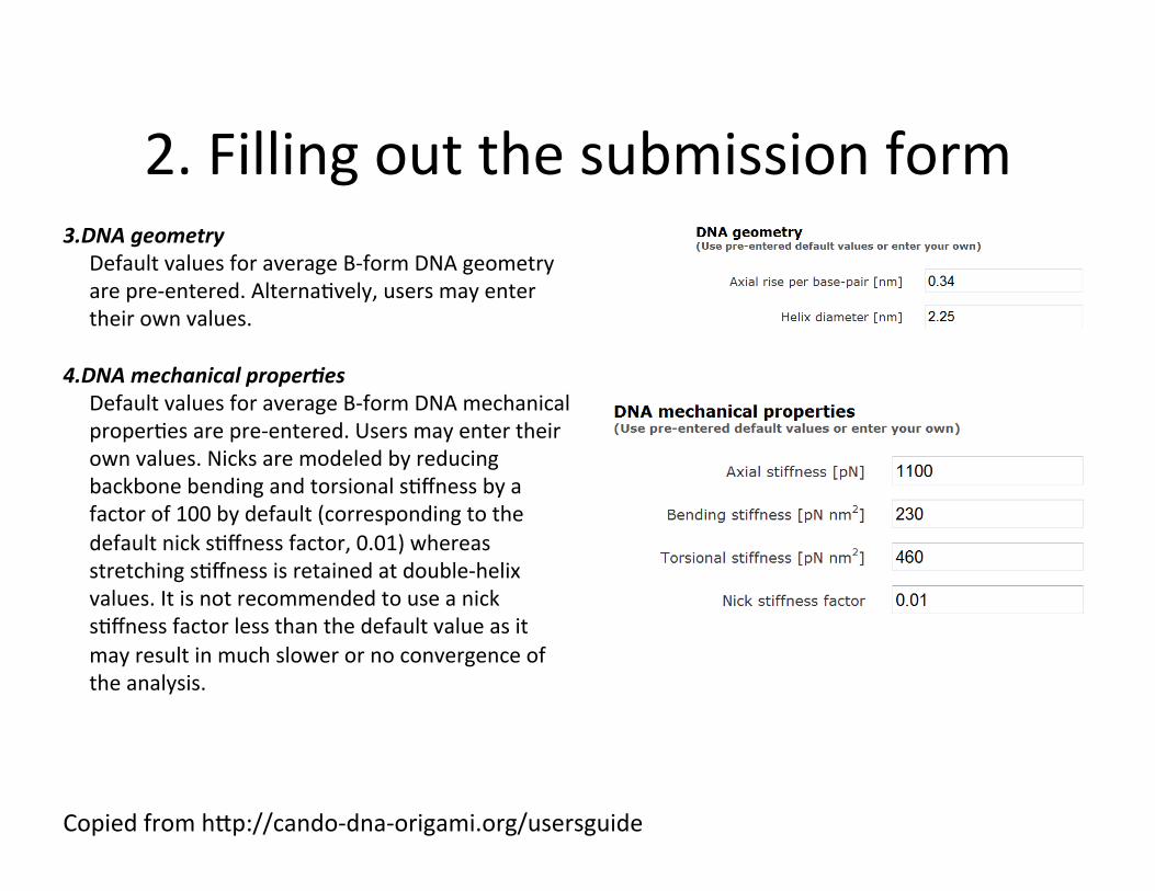
3. DNAgeometryDefaultvaluesforaverageB-formDNAgeometryarepre-entered.AlternaJvely,usersmayentertheirownvalues.
4. DNAmechanicalproper6esDefaultvaluesforaverageB-formDNAmechanicalproperJesarepre-entered.Usersmayentertheirownvalues.NicksaremodeledbyreducingbackbonebendingandtorsionalsJffnessbyafactorof100bydefault(correspondingtothedefaultnicksJffnessfactor,0.01)whereasstretchingsJffnessisretainedatdouble-helixvalues.ItisnotrecommendedtouseanicksJffnessfactorlessthanthedefaultvalueasitmayresultinmuchslowerornoconvergenceoftheanalysis.

2.Fillingoutthesubmissionform
CopiedfromhPp://cando-dna-origami.org/usersguide
5. Modelresolu6onCanDoanalysisisperformedatthecoarsemodelresoluJonbydefault.UsershaveanopJontousethefinemodelresoluJonthatcomputestheshapeandflexibilityatasinglebasepairresoluJon.However,theuseofthecoarsemodelisappropriatetoobtainquickfeedbackforiniJaldesignsasitsignificantlyreducesthecomputaJonJme.HerewechoosethefineresoluJonforpurposesofthistutorial.
6. caDNAno(.json)fileBrowsetothelocaJonofyourcaDNAnodesignfile.
7. LaCcetypeUsersmustchoosethelalcetype,eitherhoneycomborsquare. 3.PressSubmit

4.Viewingtheresults
CopiedfromhPp://cando-dna-origami.org/usersguide
OncetheCanDoanalysisiscompleted,userscandownloadasinglezipfilecontainingthefollowingresultsontheresultpage.1. Thedeformedstructureinunicolor(****_deformedShape.bild)2. Thedeformedstructurewithroot-mean-squarethermalfluctuaJonsindicatedincolorsuperimposed
(****_RMSF.bild)3. MoviesofthermalfluctuaJonsinthreeorthogonalviews(e.g.fluctuaJons_view1.avi)4. MoviesofsoluJonshapecalculaJon(e.g.loadsteps_view1.avi)5. Thelowestfivenormalmodesofthedeformedstructureat1kBT,2kBT,3kBT,and10kBTinunicolor(e.g.
****_Mode1_1KbT.bild)
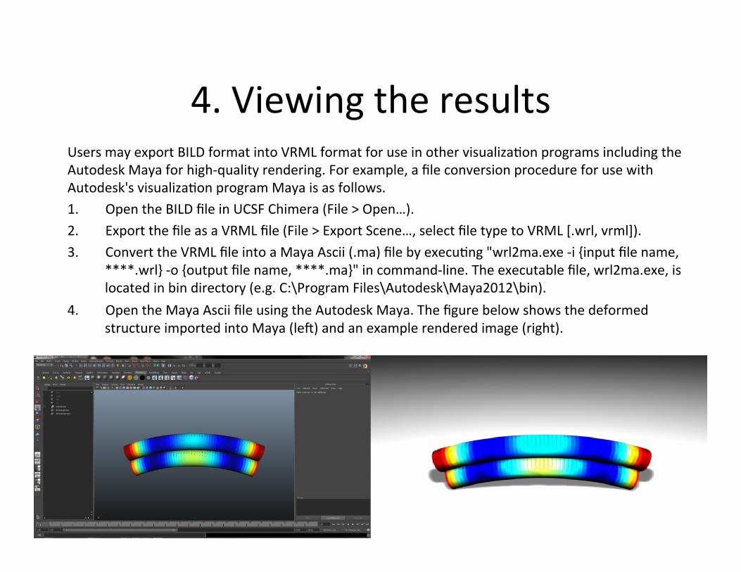
UsersmayexportBILDformatintoVRMLformatforuseinothervisualizaJonprogramsincludingtheAutodeskMayaforhigh-qualityrendering.Forexample,afileconversionprocedureforusewithAutodesk'svisualizaJonprogramMayaisasfollows.1. OpentheBILDfileinUCSFChimera(File>Open…).2. ExportthefileasaVRMLfile(File>ExportScene…,selectfiletypetoVRML[.wrl,vrml]).3. ConverttheVRMLfileintoaMayaAscii(.ma)filebyexecuJng"wrl2ma.exe-i{inputfilename,
****.wrl}-o{outputfilename,****.ma}"incommand-line.Theexecutablefile,wrl2ma.exe,islocatedinbindirectory(e.g.C:\ProgramFiles\Autodesk\Maya2012\bin).
4. OpentheMayaAsciifileusingtheAutodeskMaya.ThefigurebelowshowsthedeformedstructureimportedintoMaya(lep)andanexamplerenderedimage(right).
4.Viewingtheresults

RecommendedReading
• SubmicrometreGeometricallyEncodedFluorescentBarcodesSelf-assembledfromDNA
• ControllingtheFormaJonofDNAOrigamiStructureswithExternalSignals
• ALogic-GatedNanorobotforTargetedTransportofMolecularPayloads

Arbonaetal–ModellingthefoldingofDNAorigami
Modelling the folding of DNA origamiJean-Michel Arbona ⇤,Juan Elezgaray ⇤ , and Jean-Pierre Aime ⇤
⇤CBMN, UMR 5248, CNRS, 2 r. R. Escarpit, 33600 Pessac
Submitted to Proceedings of the National Academy of Sciences of the United States of America
DNA based nanostructures built on a long single stranded DNAsca↵old, known as DNA origamis, are nowadays the basis of manyapplications. These applications range from the control of single-molecule chemical reaction networks to the organization at thenanometer scale of various molecules including proteins and carbonnanotubes. However, many basic questions concerning the mech-anisms of formation of the origamis have not been addressed sofar. For instance, the robustness of di↵erent designs against factors,such as the internal topology, or the influence of the staple pat-tern, are handled empirically. We have built a model for the foldingand melting processes of DNA origamis that is able to reproduceaccurately several thermodynamic quantities measurable from UVabsorption experiments. The model can also be used to design anew distribution of crossovers that increases the robustness of theDNA template. The model provides predictions among which a fewof them have been already successfully verified. Therefore, in spiteof its complexity we propose an algorithm that gives the capabil-ity to design and fabricate templates with dedicated properties, anecessary step for technological development.
DNA folding | mass-action kinetics
Abbreviations: ssDNA, single stranded DNA; dsDNA, double stranded DNA; bp, base
pair
S ince its discovery [1], DNA origamis have boosted re-searchers creativity to fabricate template biosensing
structures or dynamical systems in 2D and 3D. DNA origamisare based on precise algorithms that allow the fabricationof self-assembled addressable templates with nanometer scaleaccuracy. This unique combination of algorithm and self-assembled fabrication method has lead to a wealth of newstructures and devices. Besides immediate applications suchas biosensors [2], many strategies take use of DNA dynamicalbehaviours to achieve complex functions or structure reconfig-uration. Prescribed tracks have been used for nanomachinesand nanorobots [3] [4] [5] while strand displacement tech-nique [6] has been used to reorganise origamis structures [7][8]. However, despite these innovative realisations, the foldingprocess of DNA origamis remains poorly understood. In thispaper we study in depth the process of formation of origamisthrough the analysis of melting and annealing curves. Alsosimple origami structures with a template of 64 bp long thatmimic basic units of DNA origamis are studied.
The process of formation of a DNA origami can be anal-ysed by collecting the fluorescence intensity of a reporter dye[9] or by monitoring the variation of its UV absorption as afunction of the temperature (melting curve) [10]. UV mea-surement are based on the fact that hybridized bases absorbless than open bases. The fraction of hybridized bases (de-gree of pairing ✓(T ) ) can be obtained from raw absorbancemeasurements as indicated in SI. The derivative of the melt-ing curve of a short dsDNA displays a maximum at a welldefined temperature hereafter identified as the melting tem-perature (T
m
). For longer dsDNA macromolecules, severalmaxima may appear ,[11] [12], as a signature of the exis-tence of contiguous regions that fold (or melt) independently.DNA origamis are made of a 7200 bases long ssDNA scaffold(M13mp18) folded with a set of about 200 complementaryshort ssDNA (32 bases long) called staples. The set of staplesdepends on the detailed connectivity. However, the average
AT and GC content of two origamis based on the same scaf-fold is identical. Fig. a represents the derivative of the meltingcurves of three different origamis based on the same scaffold.The observed differences Fig. a point to the existence of mech-anisms of folding that are very different from those at workin dsDNA macromolecule. To further stress this difference,Fig. b represents the results obtained by assuming that allthe staples fold independently. Notice that the hypothesisof an uncorrelated staple folding process leads to a shift ofthe melting temperature of 10 �C and to a calculated relativestability of the three origamis inverted with respect to theexperimental data.
Staples are designed to hold together regions of the scaf-fold that, otherwise, would be separated by a (possibly) longsequence. The binding of a staple to the scaffold is hinderedby an entropic penalty that depends on the length of this re-gion. At high temperature, this region of the scaffold formsa coil. Depending on the T
m
at which this staple binds, itmay happen that other staples have already folded within thecoil, reducing the entropy. Therefore, the binding of any sta-
Fig. 1. (a)Derivative d✓/dT of the degree of pairing with respect to temperaturefor the three DNA origamis represented in the insets. (b) d✓/dT for a model wherethe staples fold independently.
Fig. 2. (a) Schematic representation of the connectivity of the small origami.(b)B1 staple is in the ’outer’ position,(c) B2 staple in the ’inner’ position. (b) and(c) show that the binding of staples in the outer (b) or inner (c) positions are verydi↵erent.
Reserved for Publication Footnotes
www.pnas.org — — PNAS Issue Date Volume Issue Number 1–7
arX
iv:1
111.
7130
v1 [
cond
-mat
.mes
-hal
l] 3
0 N
ov 2
011
Arbona,J.M.,Elezgaray,J.,&Aimé,J.P.(2011).ModellingthefoldingofDNAorigami.arXivpreprintarXiv:1111.7130.RetrievedfromhPp://arxiv.org/abs/1111.7130

Fig. 3. The derivative d✓/dT reported in the four figures corresponds to the folding of the dotted staple. a) experimental data on the folding of B1(AT) cases (A,B,D) inthe absence of B2(GC), cases (C,E) with B2 already folded; b) experimental data on B2 without B1; c) experimental data on B1m; d) experimental data on B2m
ple depends on the previous binding state of the other staples,leading to a field of interacting loops of various sizes. Stated insuch a way, the problem of describing the folding (unfolding)path of DNA origamis appears untractable. In an attempt tohave a more quantitative picture, we first simplify the problemand study a simple structure made of three ssDNA. This threestrand pattern can be viewed as a building block of the DNAorigamis (Fig. a). This preliminary study intends to shedsome light on the local pairing in a DNA origami. From theseexperiments, we will derive effective thermodynamic parame-ters that will be used to describe the folding of DNA origamis.
Small origamiWe designed a DNA construction (called small origami)
made of two ssDNA 32b long (staples) and a 64b long ssDNA(scaffold). This structure is similar to DAO structures[13] andcomparable in size and shape to JX and PX structures whichhave already been studied experimentally [14], and theoreti-cally [15], [16]. Three different sets of staples based on thesame structure were chosen to quantitatively evidence coop-erative effects during the binding of the staples. In the firsttwo sets, the two staples (B1 and B2) have very different com-positions: the sequence of B1 only contains A or T nucleotidewhereas B2 only contains G or C nucleotide. Accordingly,their melting temperatures are far apart, respectively 57 �Cand 91 �C. This allows to differentiate the two staples inthe melting curve. The third set has two staples, B1m andB2m, designed with chemical sequences different enough toavoid mispairing with the 64b template B0. They have closemelting temperatures (respectively 77 �C and 80 �C ) as theirAT/GC ratio are similar.
The topology of the binding is illustrated in (Fig. ): eachstaple contains two contiguous parts, 16b long, that bind tothe scaffold. In (Fig. a), B1 is in the ’outer’ position, B2 is inthe ’inner’ position. The difference between these two waysof binding can be further stressed by considering what hap-pens when only half of the staple is hybridized. In the ’outer’position, the unbound parts of the staple and the scaffold arelocated on the same side of the bound moities (Fig. b). Inthe ’inner’ position, the unbound parts are on opposite sides(Fig. c). Besides the existence of this entropic hindrance,the inner position requires that double-helical domains stayin close contact, which could result in additional instability.Motivated by these considerations, we have investigated threedifferent cases:
• B2 is located in the inner part, B1 in the outer part.
• B2 is located in the outer part, B1 in the inner part.• B1m is located in the outer part, B2m in the inner part.
In (Fig. 3a) we report the derivative of the melting curvesthat show the behaviour of the B1 strand for different configu-rations. Fig. 3a.A corresponds to the melting curve of B1 withits complementary B1: it shows a maximum peak at 57 �Cand a half width of 4.5 K. We analyse first the case where B1is outer. Without the staple B2 (Fig. 3a.B), the structureproduces a loop or bulge, as described in [17] that shifts thefree energy towards a lower value and decreases the meltingtemperature to 48.5 �C and a half width of 6 K. Thus the fold-ing is much less robust. When B1 and B2 are both presenttwo events appear on the melting curve (see (Fig S6) for bothevents). The first one at 83 �C corresponding to the folding ofB2 in the inner position (Fig. 3b.B). Then Fig. 3a.C, B1 foldsat a temperature higher than when it is alone, with a maxi-mum peak at 51.5 �C but with a similar half width. Therefore,the inner staple B2 helps the pairing of the staple B1 locatedin the outer part by suppressing part of the entropic penaltyrelated to the bulge formed by the scaffold. When B1 is inthe inner part (Fig. 3a.D), the staple hardly folds with theB0 template. The maximum peak is located at 41.5 �C , 15K lower than the value of the dsDNA and with a half widthas large as 12 K. This is three times larger than the one ofB1B1. Again, when the B2 staple is added (Fig. 3a.E ), thepairing of B1 is stabilized with a maximum peak much higherlocated at 50 �C but still with a rather large half width of 8 K.These experimental results support the evidence of a strongcorrelation between the two strands that appears when B2 isadded: the presence of B2 helps the folding of B1 whatever itslocation. Moreover, these results also show that the locationof the strand is of importance, the inner location being muchless favourable. The origin of this difference is not obvious, itmay in part be the result of an entropic penalty larger thanthe one a bulge induces, as it occurs when B1 is located inthe outer domain, but it may also be the consequence of theenergy cost of a local curvature the inner strand imposes tothe B0 template.
For B2 (Fig. 3b) one cannot investigate any correlationeffect as B1 folds at a much lower temperature. However,the influence of the location of the staple can also be checkedwith the B2 staple alone. B2B2 (Fig. 3b.A) has a maximumpeak at 91�C with a half width of 3.5 K, while when B2 is inthe inner position (Fig. 3b.B) the peak is located at 83 �Cwith a half width of 8 K. When B2 is in the outer position(Fig. 3b.C) the peak is located at 86.5�C and is slightly nar-rower (half width of 6.5 K). Therefore, the same differences
2 www.pnas.org — — Footline Author
Arbona,J.M.,Elezgaray,J.,&Aimé,J.P.(2011).ModellingthefoldingofDNAorigami.arXivpreprintarXiv:1111.7130.RetrievedfromhPp://arxiv.org/abs/1111.7130

between the inner and outer positions are observed whateverthe chemical sequence involved.
The experimental results obtained with the B1m-B2m setof staples are shown in (Fig. 3c and 3d). Again, the sametrends are observed but with less pronounced effects. Whencompared with the results obtained with the previous struc-ture, the temperature shifts and the increase of the half widthare smaller with respect to the melting curves of the dou-ble strands B1mB1m and B2mB2m. A correlation effect isalso noticeable, and is now observed for both strands B1m andB2m. When the staple B1m is in the solution, the staple B2m,which folds at a higher temperature, shows a narrower peakat a maximum 1.5 �C higher than when it is alone. Thereforepartial folding of the staple B1m helps the folding of the sta-ple B2m. Similarly to what was observed in the previous case,the correlation effect is even more effective when we considerthe influence of the B2m staple on the folding process of theB1m staple (Fig. 3c.D) shifting the T
m
from 67 �C to 72 �C.
ModelThe previous section considered the folding of simple DNAconstructions that go beyond the simplest double strandedDNA structure. The small origamis exhibited contorted struc-tures with crossovers and their associated entropic penaltiesthat depend on their location. The small origamis show co-operative and topological effects that help to start a studyon folding process of DNA origami that bear hundreds of sta-ples. For this, we need to make a few hypothesis in order tomake the problem tractable. The basic difficulty is related tothe huge number of possible configurations that need to behandled to compute average properties such as the numberof open base pairs. Long linear structures of double strandedDNA can be computed rigorously because recurrence relationscan be established in such cases [18],[12]. DNA origamis arehighly connected structures that prevent the use of linear re-currences.
Let us enumerate the working hypothesis of the model.Each staple S
i
of length |Si
| can be divided in parts that hy-bridize to non-contiguous regions of the scaffold. Let us noteSi
= partSi,1 + partS
i,2 + . . . such a division of the strandsequence (typically, each 32b staple is divided in three parts,see Fig. 5, but other partitions are possible).
Hypothesis 1: we will focus on configurations where eachpart S
i,k
is either completely hybridized or completely free.Moreover, we also disregard misfolded configurations, that is,staples that partially hybridize to the ’wrong’ part of the scaf-fold. Notice that this assumption is plausible for the one layerorigamis we consider here. For more complex, multi-layeredstructures, the staples are divided in smaller parts so thatthe probability to bind to the wrong part of the scaffold isconsiderably increased.
We will call crossover the connection between two con-tiguous parts of any staple. A crossover is not associated witha particular DNA base, it is only a convenient notation todescribe the connectivity of the origami. In the examples ofFig. , typical staples are 32 bases long and composed of threeparts (8,16,8 bases long respectively) linked by two crossoverscS
i,1 and cSi,2. On the scaffold side, a crossover is associated
with a loop, a subset of the scaffold that is hybridized (or not)depending on the presence of other staples. In the previousexample (Fig. a) B1 and B2 are decomposed in two partsconnected each one by a crossover, and B0 plays the role ofthe scaffold.
Hypothesis 2: configurations with non contiguous hy-bridized parts are forbidden. This hypothesis is well verified
when the central part of the staple is much longer than theother parts. In the following, we will note S
i
(k, l) the configu-ration where partS
i,k
, partSi,k+1, . . ., partSi,l
are hybridized,the other parts being unpaired.
The model aims to compute the probability p(Si
(k, l), T )of having a particular folded state of the staple S
i
at tempera-ture T . We will assume that at very high temperature T = T
h
,all the staples are unfolded: p(S
i
(k, l), Th
) = 0 (in practice,Th
= 90�C ). The model is recursive: p(Si
(k, l), T + dT ) iscomputed based on the knowledge of p(S
i
(k, l), T ). The in-crement dT can be both positive or negative: the algorithmstarts from T
h
, the temperature decreases down to a valueTl
, then increases again. At any temperature T , the prob-ability to observe a given configuration S
i
(k, l) will dependupon the presence (or not) of neighbour staples. Therefore,for each staple a set of neighbour staples {N
↵
(Si
)} needs tobe defined. How many staples one has to consider in thisset is a parameter of the model. In the following, the setof neighbour staples will be limited to the staples that arein the same row of the origami scaffold, and separated byless than 75b. With these notations, the probability to ob-serve the staple S
i
in a given configuration Si
(k, l) and for agiven neighbourhood N
↵
(Si
) is modelized by an equilibriumreaction: S
i
(k, l) + N↵
(Si
) ⌦ N↵
(Si
)Si
(k, l). This modellingtherefore does not consider any kinetic effect.
Hypothesis 3: because the model only keeps track of thesingle probabilities p(S
i
(k, l), T ) and not of the joint proba-bilities p(S1(k, l), S2(k
0, l0), . . . T ), it is necessary to make anadditional approximation to determine p(N
↵
(Si
), T ). Again,based on the data from the small origamis, we assume thatthere is a strong correlation between the different staples.As the processes of annealing and melting are monotonous,for two staples S
i
1 and Si
2 we venture the hypothesis thatif p(S
i
1(k, l), T ) < p(Si
2(k0, l0), T ), then the Si
2 staple waspresent in the structure when S
i
1 staple began to fold. Inorder to compute p(N
↵
(Si
), T ), let us generalize this idea andorder the staples in N
↵
(Si
) = {Si
1 , Si
2 , . . .} in such a waythat p(S
i
1 , T ) p(Si
2 , T ) . . . < p(S) = 1, where S standsfor the scaffold. According to the high correlation hypothesis,we approximate the joint probabilities in the following way:
p(Si
1 , T ) = p(Si
1 , Si
2 , . . .)
p(Si
2 , T )� p(Si
1 , T ) = p(Si
2 , Si
3 , . . .), . . .
For instance, in the case where only two crossovers in-fluence S
i
, with probability p(Si
1) both cSi
1 and cSi
2 arepresent, the probability of only having cS
i
2 is p(Si
2)� p(Si
1)
Fig. 4. Computing the entropic penalty for the three di↵erent local intermediatestates (LIS). The staple to be inserted is represented by the dotted line, the sca↵oldby the continuous line. (a) LIS1 (b) LIS2 (c) LIS3. Here, we assume that, becauseof the curvature constraints imposed by this configuration, the staple remains partlyunfolded. (d) A typical situation where two types of LIS (LIS1 at the right side of thestaple, LIS3 at the left side) can be attributed to a given crossover.
Footline Author PNAS Issue Date Volume Issue Number 3
Arbona,J.M.,Elezgaray,J.,&Aimé,J.P.(2011).ModellingthefoldingofDNAorigami.arXivpreprintarXiv:1111.7130.RetrievedfromhPp://arxiv.org/abs/1111.7130

Fig. 5. To evaluate the fraction of the staple Si
folded at the temperature T + dT , one considers the nearby staples of the staple i at T and calculates the probabilityof the di↵erent neighbouring crossovers configurations (cS
m,2, cSp,1,etc) around Si
. The origami is then subdivided in di↵erent partially folded state(eg N↵
(Si
)) with agiven probability (eg p(N
↵
(Si
))..). For each of these partial states the equilibrium constant for a partial folded configuration (N↵
(Si
)Si
(m,n)) of the staple within thisrestricted local state is calculated as explained in the energy model. The law of mass action for each partial configuration folded gives a set of coupled equations. Once solvedthey allow to determine the fraction of partial configuration folded in this environment p(N
↵
(Si
), T + dT ). Then we can calculate the total fraction of each configurationfolded p(S
i
(m,n), (T + dT ), as the sum of the fraction of those configurations in the di↵erent local states, weighted by the probability of each state.
and the probability of only having the scaffold is 1�p(Si
2). Weshow (see SI) that the set of equilibrium reactions determinesp(S
i
(k, l)) provided the equilibrium constants of these reac-tions are known. This amounts to defining an energy modelwhich is detailed in the next section.
Folding energy of a given configuration.The gain in Gibbsfree energy for hybridizing S
i
(k, l), �G(Si
(k, l), T ) =�H(S
i
(k, l), T )�T�S(Si
(k, l), T ) contains two contributions:�G = �G
NN
+ �Gtop
. The local contribution �GNN
onlydepends on the sequence of S
i
(k, l). It quantifies the gain infree energy associated with the local formation of double he-lices. We use the parameters of the nearest-neighbour model[17] with a temperature correction given in [19] (see SI Textand [19] for a detailed description).
�Gtop
gathers several contributions that depend on theconnectivity of the origami (�G
NN
depends mostly on thesequence of the scaffold and, to a less extent, on the density ofcrossovers, but not on the connectivity). With any crossover,we associate an entropic penalty. This penalty reflects thedifficulty for a staple to hybridize non-contiguous parts of thescaffold. In a first approximation, the longer the region ofthe scaffold that connects the two parts to be hybridized, thelarger the penalty. Our previous results obtained with thesmall origami show that this needs to be refined. Based onthese data, we consider three situations characterized by tran-sient arrangements of staples that we call local intermediatestates (LIS). In the first one (LIS1), the staple hybridizes tothe scaffold, forming an internal asymmetric loop [17], Fig. 3a.The length of this loop corresponds to the number of unpairedbases of the scaffold linked by the crossover. This is a gen-eralization of the ’outer’ position found for the three strandsorigami. Before the crossover formation, when only part ofthe staple is folded, the scaffold and the non hybridized partof the staple are on the same side of the hybridized part ofthe staple (Fig. b). In this case, the staple is not involved inthe path that connects the two extremities of the crossover.A particular case of LIS1, which we call LIS2, is the situa-tion where the length of the loop is zero: the crossover formslocally a Holliday junction, the staple hybridizes in the closevicinity of an already hybridized staple (Fig. 3b).
The third LIS, LIS3, corresponds to the inner position inthe small origami: the shortest path that connects the twoends of the crossover involves the staple itself (Fig. 3c). Be-
cause of this, before the crossover forms, the non hybridizedparts of the strand and the scaffold are located on oppositesides of the hybridized parts (Fig. c). Therefore, LIS3 impliesa larger penalty than LIS1 or LIS2. In the small origami, theshift in T
m
was less than 10 �C for LIS1, between 5 �C and 7�C for LIS2 and up to 15 �C for LIS3.
To each of these LIS is associated a different �Gtop
:
• �Gtop
(LIS1)= �T�Sbulge
(nT
�0.8 < nbfolded
>) (Fig. 3).The function �S
bulge
(nT
) is that of ref. [17]. nT
cor-responds to the number of bases along the scaffold and< nb
folded
> is the average value of bases folded along thescaffold (this average takes into account the probabilitiesof all the possible neighbouring configurations). The com-parison between this model and the experimental resultsfrom the small origami structure is illustrated in Fig. S3.
• �Gtop
(LIS2) = �Hloop0 � T�S
loop0 with �Hloop0 =
25.3kcal/mol and �Sloop0 = 65.0cal/mol/K. This con-
stant contribution has been derived so as to fit as well aspossible the B1-B2 experimental data (left of Fig S4) andthen applied to the B1m-B2m data (right part of Fig. S4).At the crossover, two bases that belong to S
i
face the basesconstituting the crossover made by the other strand. Theinitial enthalpic and entropic contribution of this pair ofbases is subtracted from �G
NN
as they are not nearest-neighbours anymore. One half of the contribution (nearest-neighbour model) of the two new pair of bases is added.
• �Gtop
(LIS3) = �Hunbind
� T�Sunbind
� T�Sbulge
(nt
�0.8 < nb
folded
>) (Fig. 3c): an additional penalty is addedto the entropic penalty of the loop. This intends to reflectthe stronger instability characteristic of this LIS. �H
unbind
(resp �Sunbind
) quantifies the loss of enthalpy (resp en-tropy) associated with the partial unfolding of the endsof an staple involved in this type of LIS. The number ofbases that unfold is a parameter of the model. The datain Fig. S5 correspond to the unfolding of a total of 8 bases(two bases for each of the four extremities of the staple,see Fig. 3c).
Under some circumstances (Fig. 3d), two types of LIS canbe attributed to a given crossover. In such cases, the LIS withthe smaller �G
top
is taken into account.The modelling obtained with the contributions �G
NN
and�G
top
is quite satisfactory except for a constant negative shift(⇠ �4K) of the melting temperatures. This shift indicatesthat another stabilizing mechanism that is not present in small
4 www.pnas.org — — Footline Author
Arbona,J.M.,Elezgaray,J.,&Aimé,J.P.(2011).ModellingthefoldingofDNAorigami.arXivpreprintarXiv:1111.7130.RetrievedfromhPp://arxiv.org/abs/1111.7130
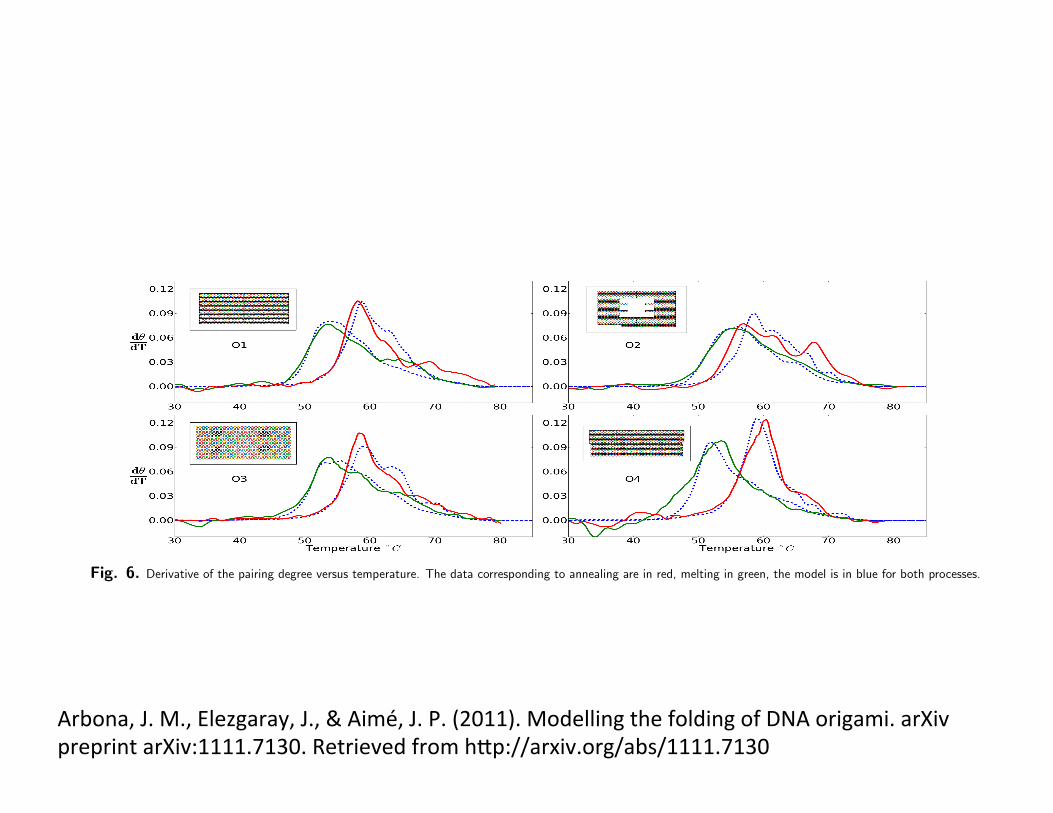
Fig. 6. Derivative of the pairing degree versus temperature. The data corresponding to annealing are in red, melting in green, the model is in blue for both processes.
constructions such as the small origamis has to be invoked.Indeed, in the folded structure of origamis, double-helix sec-tions are separated by distances of the order of 1nm. It is thenreasonable to think that mechanisms such as correlations be-tween counter-ions and hydration forces come also into play,as is the case when DNA condensates [20]. This electrostaticstabilizing term is proportional to the number of neighbour-ing bases n
n
that are close to the staple Si
, and to the length|S
i
(k, l)| of the partial configuration Si
(k, l) considered.
�Hn
(Si
(k, l)) = �0.132nn
|Si
(k, l)|/|Si
|(kcal/mol) [1]
The energy per base �0.132kcal/mol/base is similar tothe one needed for DNA condensation 10�1k
B
T/base to10�2k
B
T/base [21].The salinity of the buffer is taken into account via the cor-
recting terms in [22] in the case where Mg is dominant (seeSI text). Finally the number of bases folded is converted to atheoretical absorbance [23].
Comparison with the annealing-melting data of four
origamisWe considered four different DNA origamis (Fig. 6) with thesame scaffold (M13mp18 virus) and about 200 staples. O1 isthe rectangle in the original Rothemund work [1], the staplesare mostly 32b long, with folding part sequences divided in8-16-8 patterns. O2 is another rectangular origami that in-cludes a hole [24] and presents the same 8-16-8 pattern. O3has the same connectivity pattern as O1, but some stapleshave been merged two by two in four areas (coloured in blackin 6c), so that the typical staple pattern is 8-16-16-16-8. Fi-nally, O4 is another rectangular origami where a 100b longsubset of the scaffold goes from one side to the other of therectangle, forming a ssDNA ’bridge’.
For each origami, a series of annealing-melting cycles wasperformed coupled to UV-absorption measurements. Withthe protocol detailed in SI Text, the degree of pairing ✓(T )was extracted as a function of temperature. The temperatureramp (0.4 �C min�1) is typical for this one-layer origamis.The annealing-melting process is not symmetrical, the hys-teresis between the two phases of a cycle is such that themelting takes place at temperatures higher than the anneal-ing.
The overall agreement (Fig. 6) between the melting-annealing curves observed experimentally and computed withthe model is satisfactory. The model captures the hysteresisbetween the annealing and melting processes, as well as the
relative strength of this hysteresis between different origamis(O2 has only 4K shift between annealing-melting, whereas O4has 10K shift). The maximum value of the derivative, whichcan be linked to the overall enthalpy of the transition in atwo-state model, is also reproduced. This feature is robustagainst small variations of the parameters of the model.
Understanding DNA Origami design. In this section, we willrely on the model developed in the previous section to explorehow the melting temperature of the rectangular origamis de-pends on the specific connectivity. In many instances, thistype of considerations are relevant to improve the stability ofthe template against temperature when origamis are sought asplatforms controlling chemical reactions or other applicationsincluding grafting inorganic species.
Circular permutation of the scaffold.
The scaffold used for the design of rectangular origamis is acircular phage. Thus, it is possible to choose the beginning ofthe scaffold sequence anywhere so that 7248 different sets ofstaples (with same length and position, but with a differentcomposition) are possible. We compared the melting curvesgiven by those permutations on the O4 origami, permutingthe sequence in steps of 16 bases as this shifts the middleof one staple to the middle of the nearby staple. The dis-
Fig. 7. (a) Distribution of melting temperatures (annealing and melting) as afunction of the order of the circular permutation of the sca↵old strand. (b) two dif-ferent melting curves corresponding to two permutations with the lowest and highestannealing temperatures.
Footline Author PNAS Issue Date Volume Issue Number 5
Arbona,J.M.,Elezgaray,J.,&Aimé,J.P.(2011).ModellingthefoldingofDNAorigami.arXivpreprintarXiv:1111.7130.RetrievedfromhPp://arxiv.org/abs/1111.7130

Fig. 6. Derivative of the pairing degree versus temperature. The data corresponding to annealing are in red, melting in green, the model is in blue for both processes.
constructions such as the small origamis has to be invoked.Indeed, in the folded structure of origamis, double-helix sec-tions are separated by distances of the order of 1nm. It is thenreasonable to think that mechanisms such as correlations be-tween counter-ions and hydration forces come also into play,as is the case when DNA condensates [20]. This electrostaticstabilizing term is proportional to the number of neighbour-ing bases n
n
that are close to the staple Si
, and to the length|S
i
(k, l)| of the partial configuration Si
(k, l) considered.
�Hn
(Si
(k, l)) = �0.132nn
|Si
(k, l)|/|Si
|(kcal/mol) [1]
The energy per base �0.132kcal/mol/base is similar tothe one needed for DNA condensation 10�1k
B
T/base to10�2k
B
T/base [21].The salinity of the buffer is taken into account via the cor-
recting terms in [22] in the case where Mg is dominant (seeSI text). Finally the number of bases folded is converted to atheoretical absorbance [23].
Comparison with the annealing-melting data of four
origamisWe considered four different DNA origamis (Fig. 6) with thesame scaffold (M13mp18 virus) and about 200 staples. O1 isthe rectangle in the original Rothemund work [1], the staplesare mostly 32b long, with folding part sequences divided in8-16-8 patterns. O2 is another rectangular origami that in-cludes a hole [24] and presents the same 8-16-8 pattern. O3has the same connectivity pattern as O1, but some stapleshave been merged two by two in four areas (coloured in blackin 6c), so that the typical staple pattern is 8-16-16-16-8. Fi-nally, O4 is another rectangular origami where a 100b longsubset of the scaffold goes from one side to the other of therectangle, forming a ssDNA ’bridge’.
For each origami, a series of annealing-melting cycles wasperformed coupled to UV-absorption measurements. Withthe protocol detailed in SI Text, the degree of pairing ✓(T )was extracted as a function of temperature. The temperatureramp (0.4 �C min�1) is typical for this one-layer origamis.The annealing-melting process is not symmetrical, the hys-teresis between the two phases of a cycle is such that themelting takes place at temperatures higher than the anneal-ing.
The overall agreement (Fig. 6) between the melting-annealing curves observed experimentally and computed withthe model is satisfactory. The model captures the hysteresisbetween the annealing and melting processes, as well as the
relative strength of this hysteresis between different origamis(O2 has only 4K shift between annealing-melting, whereas O4has 10K shift). The maximum value of the derivative, whichcan be linked to the overall enthalpy of the transition in atwo-state model, is also reproduced. This feature is robustagainst small variations of the parameters of the model.
Understanding DNA Origami design. In this section, we willrely on the model developed in the previous section to explorehow the melting temperature of the rectangular origamis de-pends on the specific connectivity. In many instances, thistype of considerations are relevant to improve the stability ofthe template against temperature when origamis are sought asplatforms controlling chemical reactions or other applicationsincluding grafting inorganic species.
Circular permutation of the scaffold.
The scaffold used for the design of rectangular origamis is acircular phage. Thus, it is possible to choose the beginning ofthe scaffold sequence anywhere so that 7248 different sets ofstaples (with same length and position, but with a differentcomposition) are possible. We compared the melting curvesgiven by those permutations on the O4 origami, permutingthe sequence in steps of 16 bases as this shifts the middleof one staple to the middle of the nearby staple. The dis-
Fig. 7. (a) Distribution of melting temperatures (annealing and melting) as afunction of the order of the circular permutation of the sca↵old strand. (b) two dif-ferent melting curves corresponding to two permutations with the lowest and highestannealing temperatures.
Footline Author PNAS Issue Date Volume Issue Number 5Arbona,J.M.,Elezgaray,J.,&Aimé,J.P.(2011).ModellingthefoldingofDNAorigami.arXivpreprintarXiv:1111.7130.RetrievedfromhPp://arxiv.org/abs/1111.7130

tribution of temperatures corresponding to the maximum ofthe derivative for the annealing and melting curves (Fig. 6a)shows an amplitude of variation of about 4 �C . Also, cor-relations exist between consecutive permutations. Dependingon the permutation, the melting curves can be very differentin shape (Fig. 6b).
Decreasing the number of crossovers.
In our model, a penalty is associated to each crossover. Re-ducing the number of crossovers should in principle increasethe stability in the annealing process. We started from theO1 shape to reduce the number of crossovers, as its designis more regular. In the initial origami there is a length of32 bases between two crossovers, which corresponds to threeperiods in the double helix. Increasing the distance betweencrossovers leads to consider 54 bases (5 double-helix periods).We considered two possibilities, illustrated in Fig. 6: staples27b long, split in 13-14, and staples 54b long, split in 13-27-14 (O5 origami). Indeed, there is a trade-off between the gainin enthalpy when increasing the length of the staple, and theadditional penalty of having two crossovers/ staple insteadof only one. Our model shows that the net gain in stability,compared to the initial 8-16-8 staple strategy, is almost 20�C (Fig. 6 O5). Again, the comparison with the experimentsis excellent. Notice that decreasing the number of crossoverscould have an impact on the flexibility of the origami.
ConclusionDNA origamis appear as a versatile tool to design varioustypes of DNA based nanostructures. We have introduceda simple algorithm based on known thermodynamic prop-
erties of dsDNA and their parameterization with the NN-model. This algorithm provides a reasonable account of theobserved melting and annealing behaviour of DNA origamis.The model reproduces hysteresis and melting temperatures, aswell as the width of the melting curve. It emphasizes the roleof cooperativity in the folding process by introducing correla-tions between the probability of presence of neighbour staples.Finally, it allows to improve the thermal stability by quanti-fying the effect of different construction factors such as staplelength and density of crossovers. Extensions to 3D [25] [26]and structures other than origami [27] are envisioned, as wellas tests at the single molecule level (FRET). AFM measure-ment of Origami as function of the temperature [28] could beenvisaged to compare the observed structure with the model.
ACKNOWLEDGMENTS. This work was partially supported by CNRS (PIR fund-ing). Thanks to Carmelo di Primo for letting us use its equipment. Thanks toJean-Louis Mergny for letting us use its equipment and to Thao Tran for the OrigamiO2.
Fig. 8. Annealing curves of the O1 and O5 origamis. The two origamis correspondto the same sca↵old pattern, but di↵erent staple pattern (solid line = experimentaldata, dashed line = theoretical curves)
1. Rothemund, P. (2006) Folding DNA to create nanoscale shapes and patterns. Nature440, 297–302.
2. Ke, Y, Lindsay, S, Chang, Y, Liu, Y, & Yan, H. (2008) Self-assembled water-solublenucleic acid probe tiles for label-free RNA hybridization assays. Science 319, 180–3.
3. Lund, K, Manzo, A, Dabby, N, Michelotti, N, Johnson-Buck, A, Nangreave, J, Tay-lor, S, Pei, R, Stojanovic, M, Walter, N, et al. (2010) Molecular robots guided byprescriptive landscapes. Nature 465, 206–210.
4. Gu, H, Chao, J, Xiao, S, & Seeman, N. (2009) Dynamic patterning programmed byDNA tiles captured on a DNA origami substrate. Nature Nanotechnology.
5. Wickham, S, Endo, M, Katsuda, Y, Hidaka, K, Bath, J, Sugiyama, H, & Turber-field, A. (2011) Direct observation of stepwise movement of a synthetic moleculartransporter. Nature Nanotechnology 6, 166–169.
6. Zhang, D & Seelig, G. (2011) Dynamic DNA nanotechnology using strand-displacement reactions . Nature chemistry 3, 103–113.
7. Andersen, E, Dong, M, Nielsen, M, Jahn, K, Subramani, R, Mamdouh, W, Golas, M,Sander, B, Stark, H, Oliveira, C, et al. (2009) Self-assembly of a nanoscale DNA boxwith a controllable lid. Nature 459, 73–76.
8. Han, D, Pal, S, Liu, Y, & Yan, H. (2010) Folding and cutting DNA into reconfigurabletopological nanostructures. Nature nanotechnology 5, 712–717.
9. Castro, C, Kilchherr, F, Kim, D, Shiao, E, Wauer, T, Wortmann, P, Bathe, M, &Dietz, H. (2011) A primer to sca↵olded DNA origami. Nature Methods 8, 221–229.
10. Mergny, J & Lacroix, L. (2003) Analysis of thermal melting curves. Oligonucleotides13, 515–537.
11. Blossey, R & Carlon, E. (2003) Reparametrizing the loop entropy weights: E↵ect onDNA melting curves. Phys. Rev. E 68, 061911.
12. Jost, D & Everaers, R. (2009) A Unified Poland-Scheraga Model of Oligo-and Polynu-cleotide DNA Melting: Salt E↵ects and Predictive Power. Biophysical journal 96,1056–1067.
13. Fu, T & Seeman, N. (1993) DNA double-crossover molecules. Biochemistry 32,3211–3220.
14. Spink, C, Ding, L, Yang, Q, Sheardy, R, & Seeman, N. (2009) Thermodynamics offorming a parallel DNA crossover. Biophysical journal 97, 528–538.
15. Maiti, P, Pascal, T, Vaidehi, N, & Goddard III, W. (2004) The stability of Seeman JXDNA topoisomers of paranemic crossover (PX) molecules as a function of crossovernumber. Nucleic acids research 32, 6047.
16. Maiti, P, Pascal, T, Vaidehi, N, Heo, J, & Goddard, W. (2006) Atomic-Level Simu-lations of Seeman DNA Nanostructures: The Paranemic Crossover in Salt Solution.Biophysical journal 90, 1463–1479.
17. SantaLucia Jr, J & Hicks, D. (2004) The thermodynamics of DNA structural motifs..Annual review of biophysics and biomolecular structure 33, 415.
18. Poland, D & Scheraga, H. (1970) Theory of helix-coil transitions in biopolymers.(Acad. Pr.) .
19. Hughesman, C, Turner, R, & Haynes, C. (2011) Correcting for Heat Capacity and5’-TA Type Terminal Nearest Neighbors Improves Prediction of DNA Melting Tem-peratures Using Nearest-Neighbor Thermodynamic Models. Biochemistry.
20. Strey, H, Podgornik, R, Rau, D, & Parsegian, V. (1998) Dna-dna interactions. Currentopinion in structural biology 8, 309–313.
21. Bloomfield, V. (1997) DNA condensation by multivalent cations. Biopolymers 44,269–282.
22. Owczarzy, R, Moreira, B, You, Y, Behlke, M, & Walder, J. (2008) Predicting sta-bility of DNA duplexes in solutions containing magnesium and monovalent cations.Biochemistry 47, 5336–5353.
23. Tataurov, A, You, Y, & Owczarzy, R. (2008) Predicting ultraviolet spectrum of sin-gle stranded and double stranded deoxyribonucleic acids. Biophysical Chemistry 133,66–70.
24. Endo, M, Katsuda, Y, Hidaka, K, & Sugiyama, H. (2010) Regulation of DNA methy-lation using di↵erent tensions of double strands constructed in a defined DNA nanos-tructure. Journal of the American Chemical Society 132, 1592–1597.
25. Douglas, S, Dietz, H, Liedl, T, Hogberg, B, Graf, F, & Shih, W. (2009) Self-assemblyof DNA into nanoscale three-dimensional shapes. Nature 459, 414.
26. Dietz, H, Douglas, S, & Shih, W. (2009) Folding DNA into twisted and curvednanoscale shapes. Science 325, 725.
27. Hansen, M, Zhang, A, Rangnekar, A, Bompiani, K, Carter, J, Gothelf, K, & LaBean,T. (2010) Weave Tile Architecture Construction Strategy for DNA Nanotechnology.Journal of the American Chemical Society.
28. Rajendran, A, Endo, M, Katsuda, Y, Hidaka, K, & Sugiyama, H. (2011) Photo-cross-linking-assisted thermal stability of DNA origami structures and its applicationfor higher-temperature self-assembly. Journal of the American Chemical Society.
6 www.pnas.org — — Footline Author
Arbona,J.M.,Elezgaray,J.,&Aimé,J.P.(2011).ModellingthefoldingofDNAorigami.arXivpreprintarXiv:1111.7130.RetrievedfromhPp://arxiv.org/abs/1111.7130