how to geospatially reference a pdf into microstation · how to geospatially reference a pdf into...
TRANSCRIPT

How to Geospatially Reference a PDF into MicroStation (This method creates a geospatially placed background image in your CAD file, you cannot select the line work)
Separate your PDF into individual sheets if it is in a batch PDF
Adobe :
1. Go to Tools>Pages> Extract
2. Specify which page(s) you want to extract
3. Select the option “Extract Pages as Separate Files”
Bluebeam:
1. Go to Document > Pages > Extract Pages
2. Specify which page(s) you want to extract
3. Check off the option “Extract Pages as Separate Files”
Find Coordinate Data on the Plan Sheet
In order to correctly place the PDF we need Geographic data to anchor it to. In the following
example control points on the plan sheet are used.

1. Identify at least 3 coordinated points on the sheet, ideally spread out.
Figure 1: Three Control Points with Coordinates Have Been Identified
2. In an Excel spreadsheet type in the Point Name, Northing, Easting, Elevation and Style for each
point. ( Set elevation to zero for each point, raster will not warp properly otherwise)

Figure 2: Close up of Control Points and Coordinates on the Plan Sheet

Figure 3: Excel Sheet with Point Data Entered
3. Go to File > Save As and change the “Save as type:” to text (tab delimited) (*.txt)

Figure 4: Selection of .txt file type
4. Open the text file you just created and make sure it appears in the same format as the
example below.
Figure 5: .txt file format

Importing the Cogo Points
5. Open MicroStation and InRoads. In Inroads go to File > Text Import Wizard
Figure 6: Text Import Wizard Command
6. In the Text Import Wizard dialog box select Cogo Points from the Data Type dropdown menu
and browse to your .txt file in the File Name field.

Figure 7: Text Import Dialog
7. Follow the 4 import steps illustrated below. On the last step match the Column Data Formats
as shown, change the header by clicking the column and selecting the corresponding format
from the dropdown list.


Figure 8: Text Import Wizard Steps

8. A message box should appear telling you the points imported correctly
Figure 9: Import Successful Message Box
9. Display the points if they do not appear immediately. You may need to zoom in to see the
points.

Figure 10: 3 Cogo points with a blow-up of one point to show detail
10. In MicroStation go to Raster Manager > File > Attach > Raster…
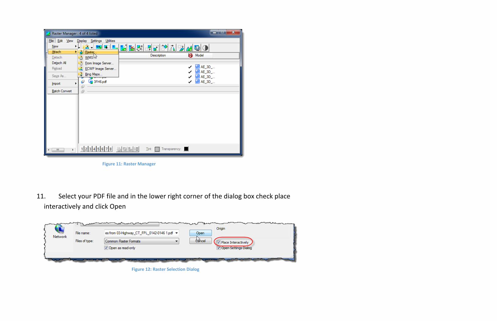
Figure 11: Raster Manager
11. Select your PDF file and in the lower right corner of the dialog box check place
interactively and click Open
Figure 12: Raster Selection Dialog

12. Drag the PDF in from left to right near your cogo points, the size is not important at this
point as long as it is viewable
Figure 13: Dragging in the PDF raster

Figure 14: PDF raster next to Cogo points
13. In the Raster manager select the Warp button and highlight your raster in the file list

Figure 15: Warp button and file list
14. The Warp Raster command will open, select Similtude (Move, Scale, Rotate) – 2 pts or +
from the Method Dropdown
Figure 16: Warp Raster Command Box

15. The lower left hand of the screen will prompt you to follow steps to warp the rater. It will
first ask you to identify the raster, you can select it in the raster Manager or click the border of
the raster itself in the drawing pane. Once selected the PDF border should highlight and the
command in the lower left of the screen should change.
16. The next prompt will ask you to identify the Image Point. This is the Point on the PDF you
want to anchor to a new point, in this example my image point is CP-3 on the PDF image.

Figure 17: Zoomed in on First Image Point
17. The next prompt will ask you to identify the Monument Point. This is the cogo point you
imported in earlier steps. You want to match the image points to the corresponding
monument points, after you click the monument point a dashed arrow will appear connecting
the image point with the monument point. Repeat this step for all of your cogo points.

Figure 18: Zoomed in on Monument Point

Figure 19: All three Image Points Connected with Monument Points
18. Once all of your points are connected, click the right mouse button to accept the warp.
The image should now move and scale to the specified points.

Figure 20: Image Point is Aligned with Monument Point (zoomed in for detail)
Using your newly imported raster image

The following steps are optional if you would like to make the background image transparent to
make it easier to draw on or layer multiple sheets on one another.
1. Open the Raster Manager and highlight the raster you want to make transparent. Then click
the square button next to the word Transparency.
Figure 21: Location of the Transparency color button in the Raster Manager

2. The Select Transparent Color Dialog box should appear. In the center pick bar set the color all
the way to the top, or set the red, green and blue scroll bars all the way to the right (255) as
shown in the figure below, then click OK.
Figure 22: Setting the transparency color to white (255)
3. Go back to the Raster Manager and with the Raster still highlighted click the Transparent
button (shown below). The raster should now change to a black background with white line
work.

Figure 23: Clicking the Transparency Icon

Figure 24: Sample Raster that has had background set to transparent
4. The next step is to make the line work a bit more clear. Go to the Raster manager and click the
Invert button, the line work should now appear more clearly.

Figure 25: Inverting the colors of the raster

Figure 26: raster with clearer line work after invert command
5. You can tint the raster to make it easier to see against other line work or to differentiate it
from other rasters if you layer them on one another. Click on the button next to the work Tint

in the raster Manager. The Tint color dialog should appear, choose a color you want to change
the line work to and select ok. The raster should now appear as the color selected.

Figure 27: Selecting a tint color

Figure 28: Raster after tint color has been changed
6. Following the previous steps you can layer another raster image on another using the same
warping method and transparency method.

Figure 29: Two geospatially located rasters layered on one another using transparency and tint
