how to start system
TRANSCRIPT

Dear students in the ECAD & DSP lab all desktops have dual operating system (OS) (WINDOS + UBUNTU/RED HAT) therefore I am sharing the some screen shots to let you know how to choose the desired OS.
1. When you will press the power button of the CPU, the given below screen/interface will appear on theMonitor/LCD Screen. As soon as this screen comes on the screen you need to trigger the downarrow key ( available on the keyboard in the arrow keys panel)
HOW TO START SYSTEM

2. When you trigger the down arrow key, the given below interface will come on the screen to choose the OS. Ubuntu based interface: select the windows 7/ windows manager setup from the OS menu.
Red Hat based interface: From this interface you have to choose “Other” to get into the windows OS.
If you fail to choose the desired OS (windows OS) then UBUNTU/RED HAT OS will automatically boot itself. To get again same OS selection menu/ interface you will need to restart your system to select the windows OS.

A Brief Introduction To Vivado® Design Suite

In this ‘Cheat Sheet’ the use of Vivado to Simulate , Synthesize and
implementation ‘Digital Design’ using VHDL is explained
AgendaHow to create a new project.Execution of .vhd file without test bench.Execution of .vhd file with test bench.Power Calculation.
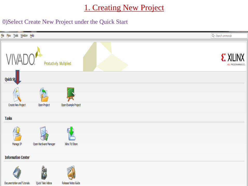
1. Creating New Project0)Select Create New Project under the Quick Start

i) Click on Next

ii)Specify the Project Name
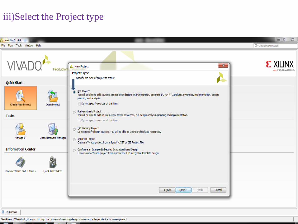
iii)Select the Project type
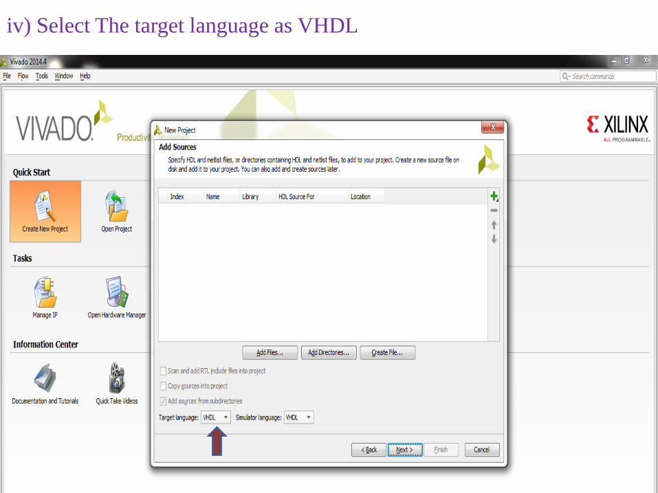
iv) Select The target language as VHDL
333
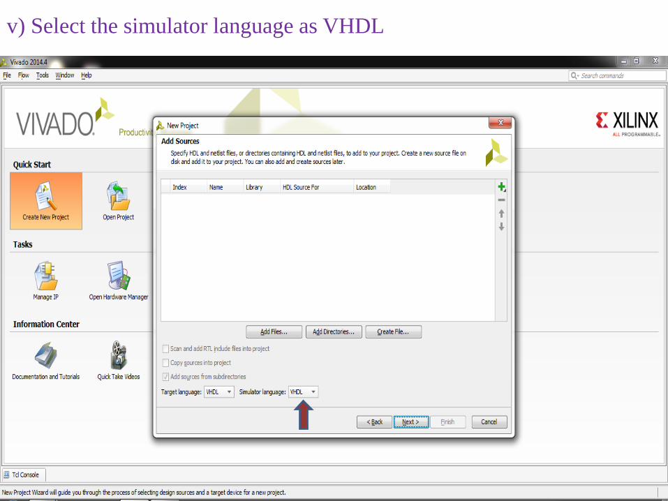
v) Select the simulator language as VHDL
333
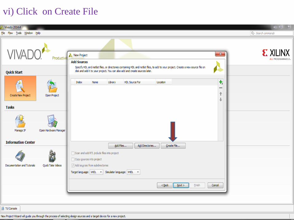
vi) Click on Create File
333

vii) Select File Type
333
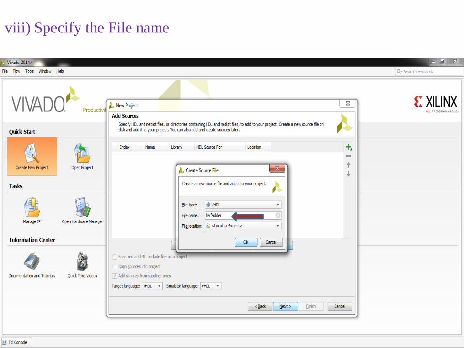
viii) Specify the File name
333
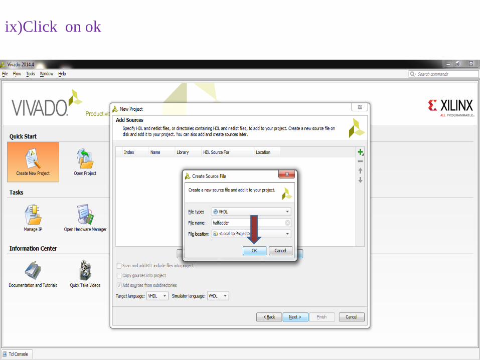
ix)Click on ok
333
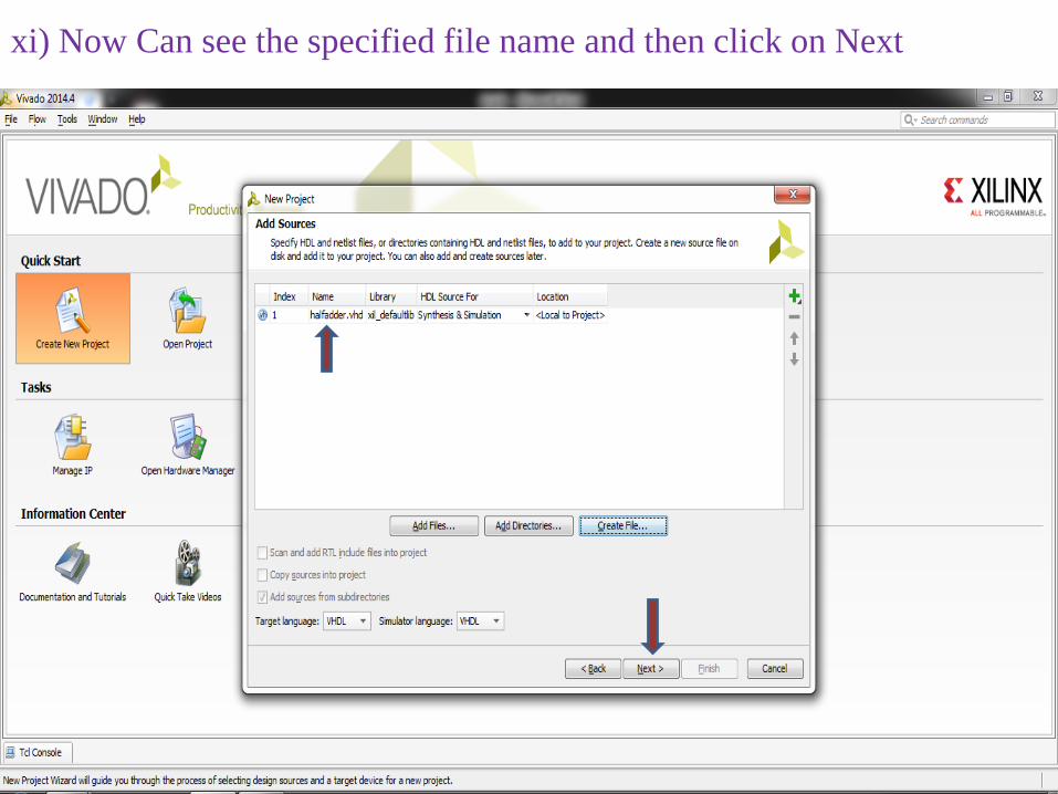
xi) Now Can see the specified file name and then click on Next

xii) Select the tab Boards here
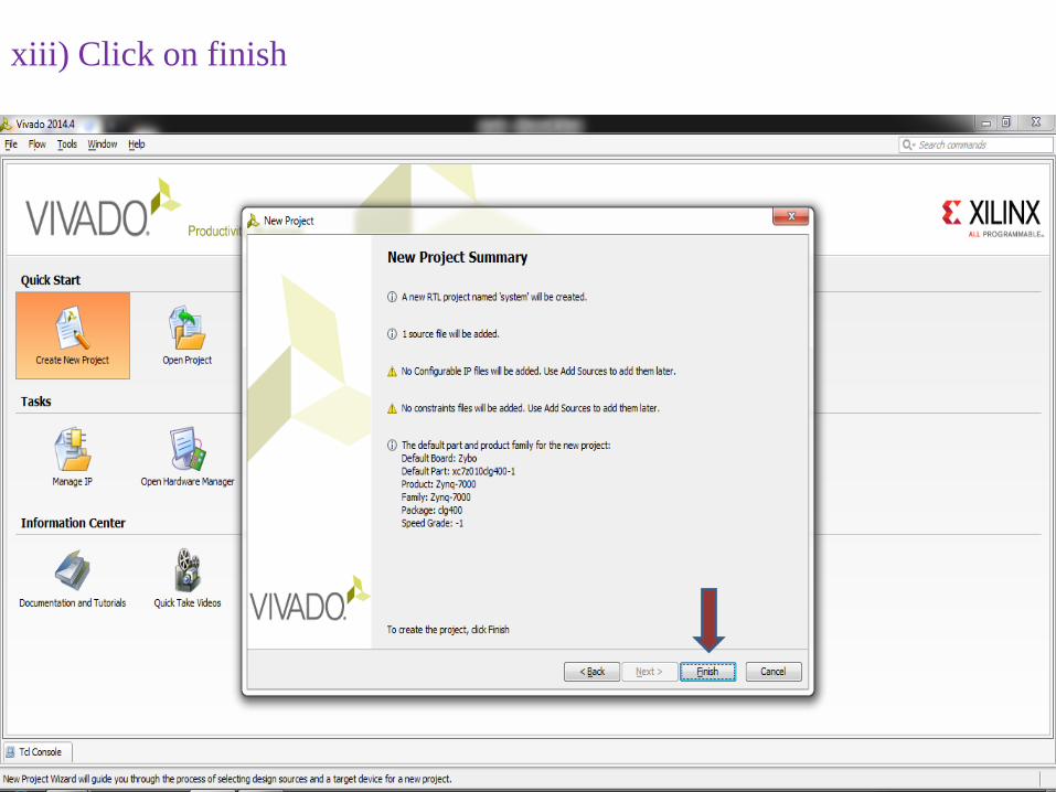
xiii) Click on finish

xiv) Now we can specify the input and output variables here.

xv)For output variables we need to select out as a type like as shown
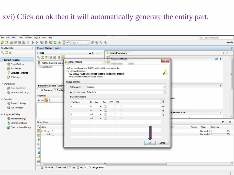
xvi) Click on ok then it will automatically generate the entity part.
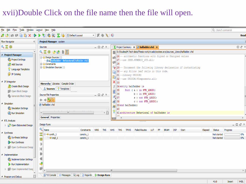
xvii)Double Click on the file name then the file will open.

xviii) Now we have to write the operation of the circuit and then save it.
These two lines performs the operation of half adder
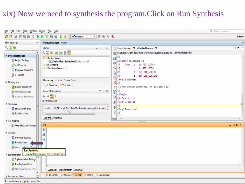
xix) Now we need to synthesis the program,Click on Run Synthesis
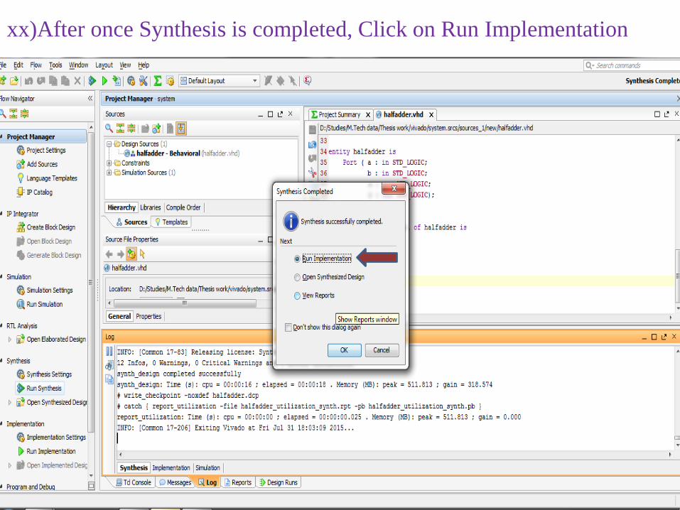
xx)After once Synthesis is completed, Click on Run Implementation
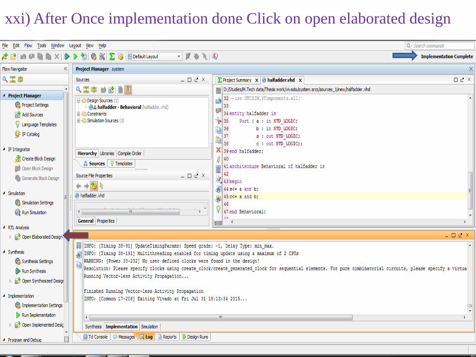
xxi) After Once implementation done Click on open elaborated design

xxii) Now it Shows the RTL schematic diagram of that circuit.
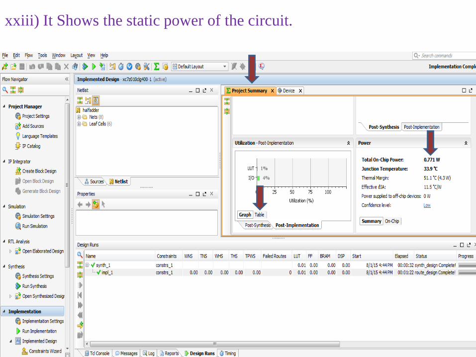
xxiii) It Shows the static power of the circuit.

xxiv) It Shows the usage of LUT’s and I/O.

2. Run Simulation without Test Bench
i) Click on Run Simulation

ii) Select Run Behavioral Simulation

iii)Now this window popped up on screen.

iv) Right click on input variable and select for force clock

v) Now this window popped up on screen.

vi) Select Leading and trailing edge values of the corresponding input

vii) Click on Run for specified time
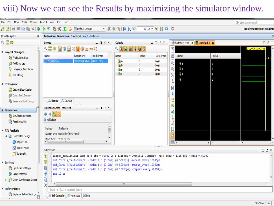
viii) Now we can see the Results by maximizing the simulator window.

ix) Output of one case having a=0,b=1.

ix) Output of another case having a=1,b=1.
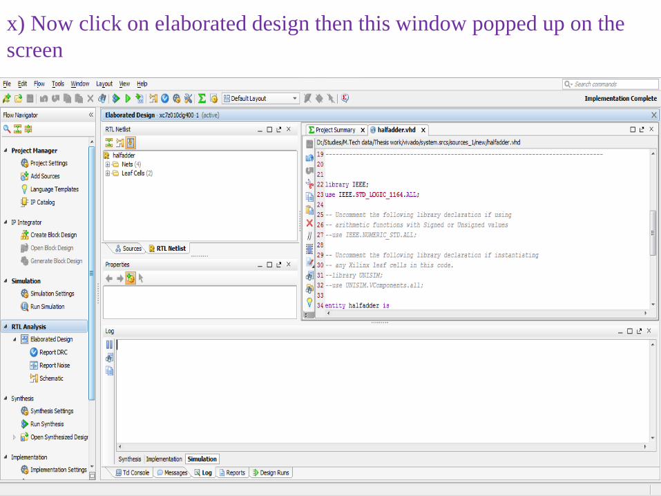
x) Now click on elaborated design then this window popped up on the screen

3. Run Simulation with Test Benchi) Click on Sources and select the file name on which file we had written the program.
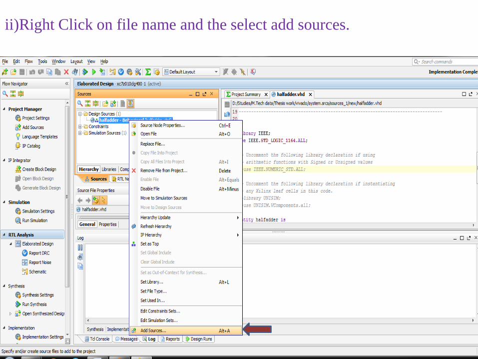
ii)Right Click on file name and the select add sources.

iii) Select the add or create simulation sources.

iv) Click on Create file option.

v) Specify the file name and then click on ok.

vi) Then it shows the testbench file name and then click on finish.

vii) Click on Ok
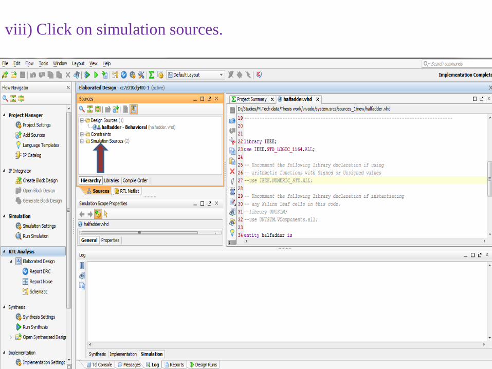
viii) Click on simulation sources.
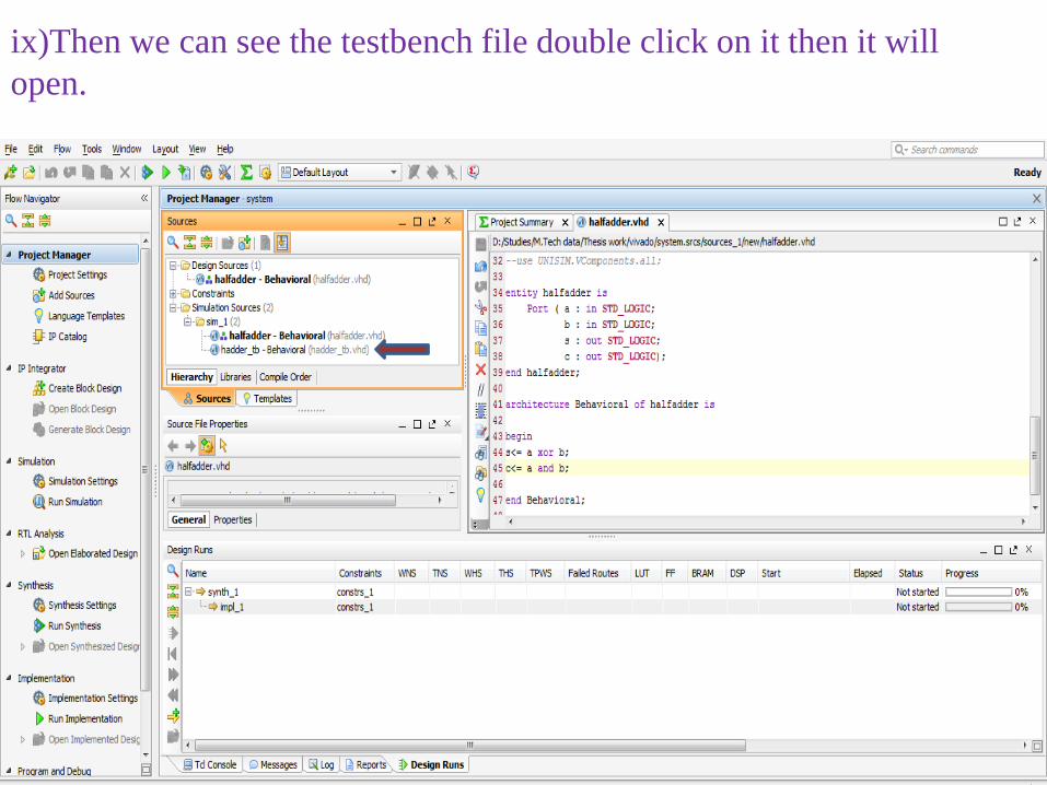
ix)Then we can see the testbench file double click on it then it will open.

x) Test cases which are applied to that circuit had shown below and after once written test cases save it.
These are the test cases which we applied to half adder
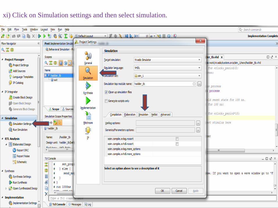
xi) Click on Simulation settings and then select simulation.
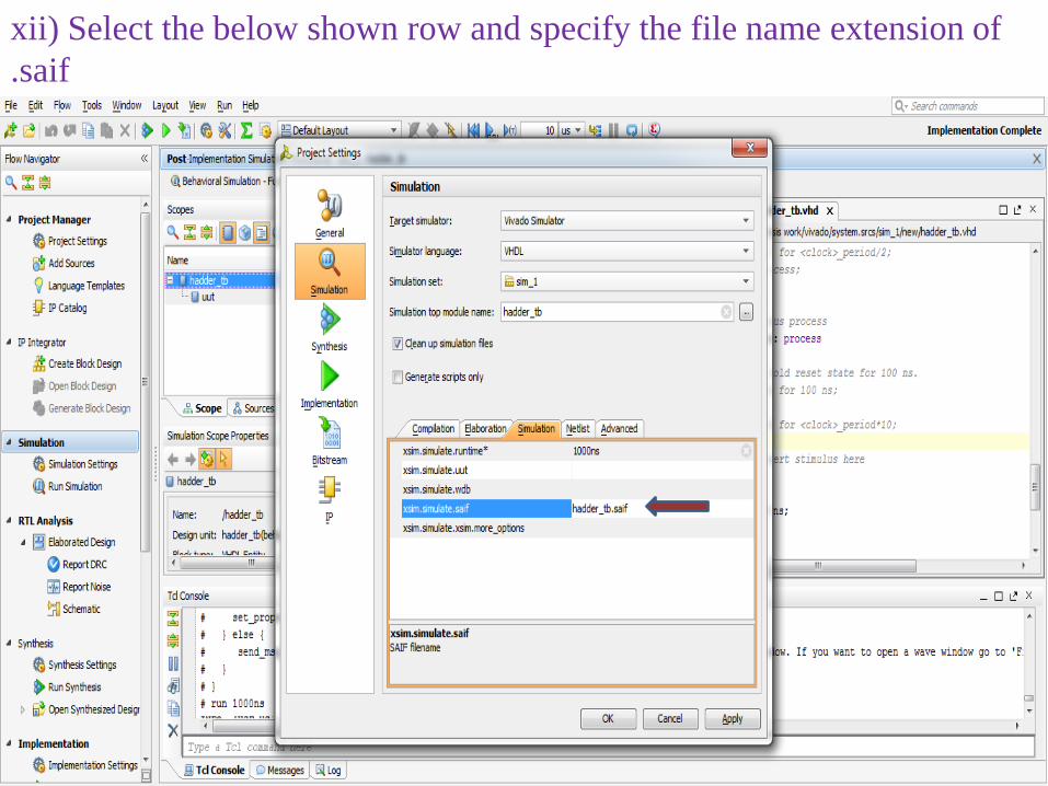
xii) Select the below shown row and specify the file name extension of .saif

xiii) After file name is specified,Click on ok

xiv) Click on Run simulation and then Select the run Behavioral simulation

xv) Once after did that it shows the output like below.

xvi) Output for another test case.

4. Power Calculationi) Click on Implemented design and then click on Report Power.
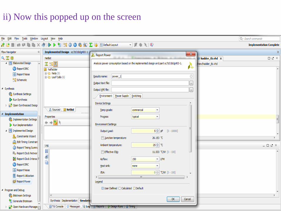
ii) Now this popped up on the screen

iii)Specify the output test file and output XPE file.

iv) Select the Switching tab and then specify the path to .saif file and then click on ok.
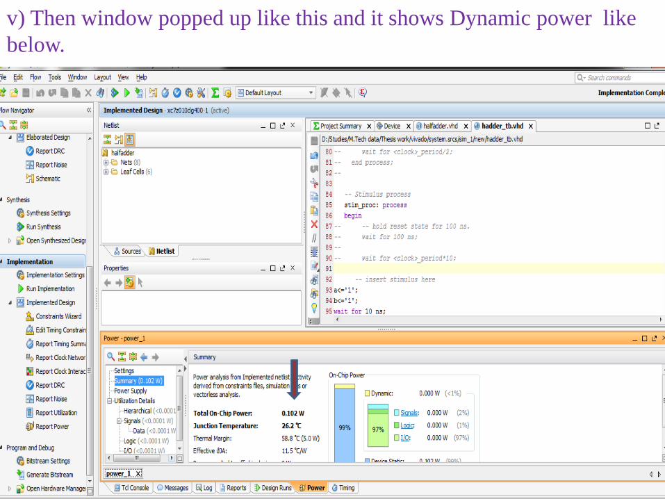
v) Then window popped up like this and it shows Dynamic power like below.