how to use anderson and jst- sm connectors. · how to use anderson and jst-sm connectors. let’s...
TRANSCRIPT

How to use Anderson and JST-SM connectors.
Tools Needed:
1. Anderson housings + pins2. JST-SM housings + pins3. Wire for crimping the pins (usually on the controller/motor etc.)
5. Anderson crimp tool6. JST-SM crimp tool7. Small flathead screwdriver8. Wire stripper9. Side snips10. Pliers

How to use Anderson and JST-SM connectors.
Let’s start with the Anderson connector.
We use the Anderson Powerpole PP15/45 series connector normally with a 30A pin, and with a 45A high detent pin for thicker gauge wire.
We only use genuine Anderson connectors - you can often tell a counterfeit by the poor construction quality and also because only genuine Anderson connectors have an “A” written on the connector here: Counterfeits are much more prone to damage than genuine Anderson connectors.
The Anderson connector is gender neutral so there is only one connector rather than a male and female side. The connectors are joined by flipping one of them 180° and pressing together.

How to use Anderson and JST-SM connectors.
You can also connect Andersons together in a chain by attaching them together on any of the four sides. You can see the tongue and groove pattern here.
The most common configuration is with them side by side horizontally...
...but they can also be stacked.
How to use Anderson and JST-SM connectors.
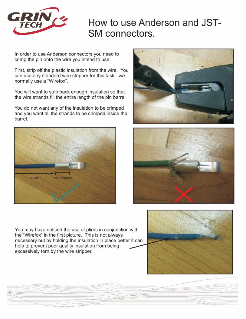
In order to use Anderson connectors you need to crimp the pin onto the wire you intend to use.
First, strip off the plastic insulation from the wire. You can use any standard wire stripper for this task - we normally use a “Wirefox”.
You will want to strip back enough insulation so that the wire strands fill the entire length of the pin barrel. You do not want any of the insulation to be crimped and you want all the strands to be crimped inside the barrel.
Wire StrandsInsulation
You may have noticed the use of pliers in conjunction with the “Wirefox” in the first picture. This is not always necessary but by holding the insulation in place better it can help to prevent poor quality insulation from being excessively torn by the wire stripper.

How to use Anderson and JST-SM connectors.
Now it’s time to crimp the pin.
We use a standard Anderson crimper with slots for 15A, 30A and 45A connectors.
Because we are using a 30A pin we will place it in the 30A slot in the crimper. You’ll notice that one part of the pin barrel has a slit running along the top - make sure this is placed facing upwards in the crimper.
Crimp down hard and then release.
Once crimped you will want to do a tug test and pull on the connector to make sure it is firmly attached to the wire. If it comes off then you are either crimping in the wrong slot, using a pin that is too big for the wire gauge or you have a defective crimping tool.
This side up
How to use Anderson and JST-SM connectors.
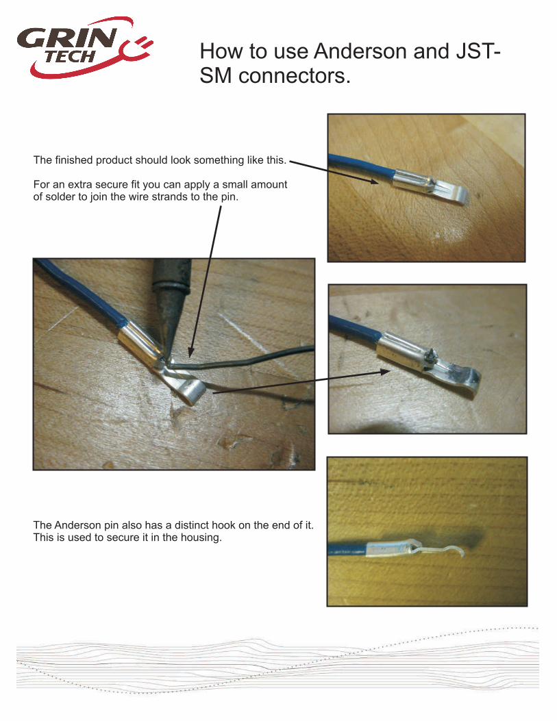
The finished product should look something like this.
For an extra secure fit you can apply a small amount of solder to join the wire strands to the pin.
The Anderson pin also has a distinct hook on the end of it. This is used to secure it in the housing.

How to use Anderson and JST-SM connectors.
So now we have the crimped pin and the housing and the next step is to combine the two.
If you look closely at the inside of the housing you will notice a small metal piece inside.
The hook of the pin will go over this little ledge and lock into place.
Take the pin and place it into the back of the housing and push until fully engaged. You should hear a click when the hook goes over the ledge. Once this step is complete you have a finished Anderson connector.
In the pictures below the one on the left shows a correct engaged Anderson pin. The one on the right shows a “recessed” Anderson pin - this is incorrect and will cause a faulty connection.
If you are having trouble getting the pin in properly (normally because the wire is too flexible so it bends) then use some pliers or a flathead screwdriver in the back of the housing to push it from behind.

How to use Anderson and JST-SM connectors.
For added security you can use a black Anderson connector holder.
When two Anderson housings are joined horizontally then a small circle is formed. You can use this circle for the black holder piece to ensure that the Andersons stay together.

How to use Anderson and JST-SM connectors.
And finally we have the high detent 45 Anderson pin. This pin is for heavier gauge wire, but it uses the same housing.
Place the pin in the 45A slot on the crimper this time, place the wire in and then crimp down firmly and release. Put the pin into the housing as you would with a 30A pin.
As with the 30A pin, you need to crimp just the wire and not the insulation.

How to use Anderson and JST-SM connectors.
One quick trick with Anderson connectors: it is possible to remove the pin from the housing and also to re-insert the same pin back into the housing.
Simply take a small flathead screwdriver and use it to lift the hook of the Anderson pin up and away from the ledge inside the housing.
You can then pull on the wire and remove the pin from the housing.
Because of this process you may actually end up bending the hook upwards and it will sometimes stay that way. In order to then reuse the pin in a housing you will need to gently bend the hook down until it is inline with the barrel of the housing.

How to use Anderson and JST-SM connectors.
After the Anderson we have the JST-SM series connector.
This is the main connector used at Grin for throttles, motor hall sensors and, of course, the Cycle Analyst.
We use connectors with 2,3,4,5 and 6 pins.
Unlike the Anderson connector the JST-SM has genders so we are dealing with two different processes now.
The crimper used for JST-SM series pins is a D-Sub crimper.
We’ll also be using the 24-30 AWG slot on the crimper for all our JST-SM crimps.

How to use Anderson and JST-SM connectors.
First we will deal with the male connector and see how to crimp the pin for this connector.
I have chosen to use the 3 pin connector but the same idea applies for the other connectors too.
Start by stripping back a small piece of the insulation to reveal the wire strands. You can do this by gently cutting the insulation with side snips and then pulling it off or you can use a Wirefox type wire stripper as used for the Anderson connector earlier in the guide. Be careful using an aggressive wire stripper because it can actually cut some of the strands away as well as the insulation.
The JST-SM series is different to the Anderson because part of the insulation gets crimped down during crimping.
There are two parts of the pin that get crimped: a higher thinner section, and a lower wider section.
The insulation gets crimped by the higher section and the wire gets crimped by the lower section.
Wire StrandsInsulation
How to use Anderson and JST-SM connectors.
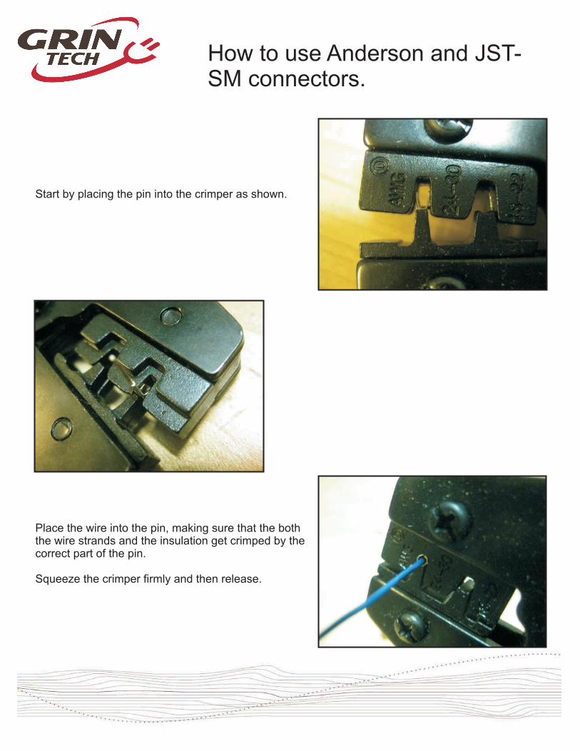
Start by placing the pin into the crimper as shown.
Place the wire into the pin, making sure that the both the wire strands and the insulation get crimped by the correct part of the pin.
Squeeze the crimper firmly and then release.

How to use Anderson and JST-SM connectors.
The finished crimp should look something like this.
You will want to do a tug test to ensure that the crimp is good and that the wire doesn’t pull out of the pin.
Here’s a couple examples of bad crimps: the pin on the left has too much insulation crimped which has led to the wire strands being pushed up through the pin. It will not fit into the housing properly because of this issue and is likely to cause a faulty connection even if you can force it into the connector. The pin on the right has no insulation crimped. Whilst some contact is made between the pin and the wire strands it can still cause a faulty connection and it also means the crimp has no strain relief and the wire is likely to pull loose over time.

How to use Anderson and JST-SM connectors.
You can also apply a small amount of solder to the pin with a soldering iron to ensure a good connection. Be careful not to apply too much solder though otherwise the pin won’t fit in the housing.

How to use Anderson and JST-SM connectors.
Another thing to look out for is that the tab on the pin sticks out prominently (it should be at a 45° angle from the pin approximately). Be careful not to push the tab in and also watch out that it doesn’t get crimped by the crimper.
Close inspection of the back of the JST connector reveals 3 small openings that are each similar in shape to an AA battery.
The top part with the small rise is a space for the tab to go. When you push the pin in the back of the connector housing ensure that the tab faces the correct way up.

How to use Anderson and JST-SM connectors.
Push the pin in the back of the housing as shown. You should hear a click when it is all the way in.
If you are having trouble getting it all the way in you can either push the back of the pin with a small flathead screwdriver....
...or you can use a small pair of pliers to pull the pin into place from the other side of the housing.

How to use Anderson and JST-SM connectors.
Now that the male side is done we can move onto the female side of the connector.
The same concept applies as the male side: the insulation gets crimped by the high thin portion of the pin, and the wire strands get crimped by the small wide portion.
Strip the wire back in the same way as shown for the male connector and again be careful not to damage the tab coming from the pin.
Crimp the pin in the same AWG 24-30 slot on the crimper.
Wire StrandsInsulation
The finished product should look something like this.
You can apply a small amount of solder too in the same way as the male pin to help ensure a solid connection.
Again you will want to do a tug test to ensure that the crimp is good and that the wire doesn’t pull out of the pin.

How to use Anderson and JST-SM connectors.
Just like the male side the female connector has 3 openings in the back.
Notice that they have the same little section that the tab goes into.
Insert the pin as shown. You should hear a click when it is properly inserted.

How to use Anderson and JST-SM connectors.
The picture on the left shows a correctly inserted pin with the opening completely filled and the metal fully visible. The picture on the right shows a pin that has not been fully engaged and this will lead to a faulty connection.
Once you have completed all the crimped pins you need you can then join the male and female connectors.
You’ll notice a latch system on top of the housings to hold them in place.

How to use Anderson and JST-SM connectors.
In the same way that it is possible to remove an Anderson pin from its housing it is also possible to remove a JST-SM pin from a female housing. It is not unfortunately very easy if at all possible to remove a pin from a male housing.
You should be able to make out part of the pin tab if you look at the underside of the housing.
By using a flathead screwdriver you can actually gently push the tab down so that it is flat and then you can pull on the wire to remove the pin from the housing.
It is not super easy to do this but it is possible and can save time if you need to switch around the pinout of a connector.
This process will mean that the tab is flat so if you want to re-insert it into the housing you will need to get the tab back up again. Take the small flathead screwdriver and use it to pry up the tab and the thinner the screwdriver head the easier it should be.
Be careful not to break off the tab - the metal is delicate and can fatigue in a short space of time. If you can’t get the tab back up or if you break the tab then bad luck! You will need to crimp on a new pin.

How to use Anderson and JST-SM connectors.
One final useful thing to know about JST-SM connectors: the picture on the left shows a frayed/worn wire where it enters the housing. This is a key thing to look out for when troubleshooting JST-SM connections. In this case it may well be that the black wire has a faulty connection and could be the one tiny reason that your ebike isn’t working! The picture on the right shows a wire that cleanly enters the housing and should then be making a good connection (as long as you crimped it properly!).
Bad connections account for a very large number of ebike troubleshooting issues and if you master the correct crimping and use of connectors you will be able to solve many ebike troubles quickly and efficiently!