how to use this install guide - amazon s3cdncontent2.idatalink.com/corporate/content/... · how to...
TRANSCRIPT
NOTICE: Automotive Data Solutions Inc. (ADS) recommends having this installation performed by a certifi ed technician. Logos and trademarks used here in are the properties of their respective owners.
WARNINGPressing the printer icon or “quick printing” this document will print
all of the guides in this compilation.
Open the Bookmarks menu and find your vehicle OR scroll down until you find the install guide for your vehicle.
Print only the pages for your vehicle using the advanced options in the Print menu.
Install your Maestro RR according to the guide for your vehicle.
HOW TO USE THIS INSTALL GUIDE1
2
3
SELECT VEHICLE PRINT PAGES NEEDED

OPTIONAL ACCESSORIESNone
PROGRAMMED FIRMWAREADS-RR(SI)-MAZ01-DS
PRODUCTS REQUIREDiDatalink Maestro RR Radio Replacement InterfaceiDatalink Compatible Radio
INSTALL GUIDEMAzDA 2
2011-2014retains steering wheel controls and adds gauges
NOTICE: Automotive Data Solutions Inc. (ADS) recommends having this installation performed by a certified technician. Logos and trademarks used here in are the properties of their respective owners.

ADS-RR(SI)-MAZ01-DS maestro.idatalink.com
Mazda 2 2011-2014
Automotive Data Solutions Inc. © 2014 2
WELCOME
NEED HELP?
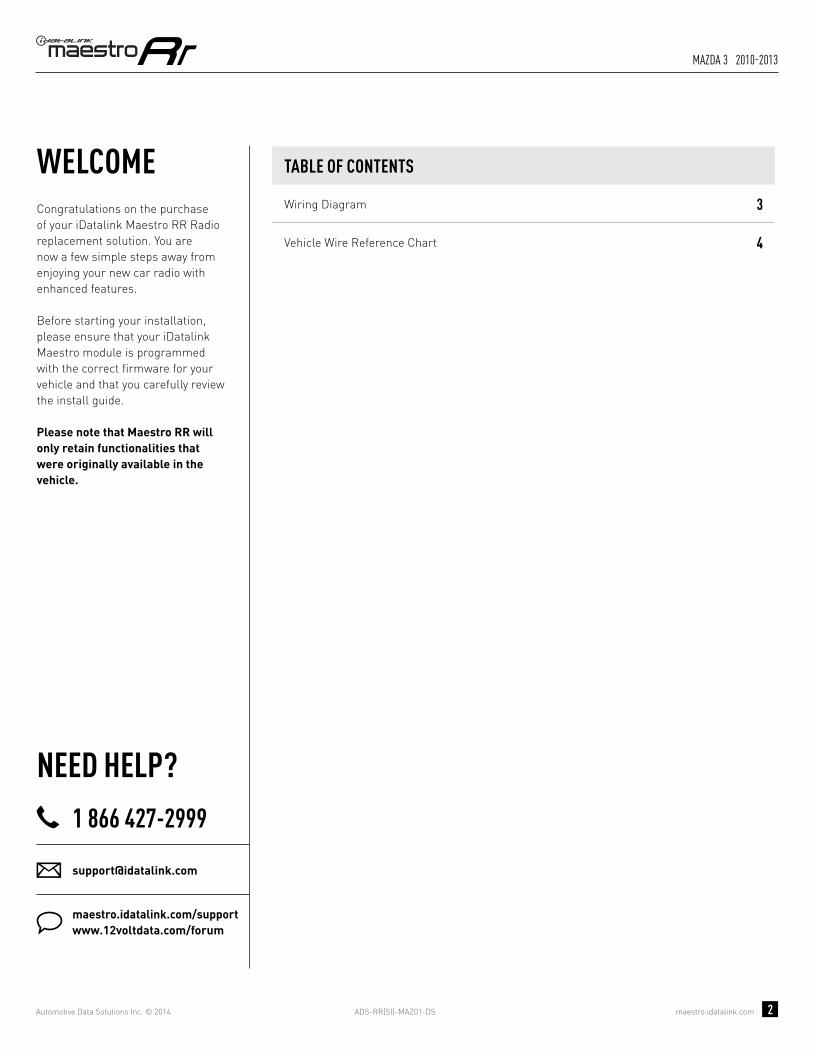
Congratulations on the purchase of your iDatalink Maestro RR Radio replacement solution. You are now a few simple steps away from enjoying your new car radio with enhanced features. Before starting your installation, please ensure that your iDatalink Maestro module is programmed with the correct fi rmware for your vehicle and that you carefully review the install guide.
Please note that Maestro RR will only retain functionalities that were originally available in the vehicle.
1 866 427-2999
maestro.idatalink.com/supportwww.12voltdata.com/forum
TABLE OF CONTENTS
Wiring Diagram 3
Vehicle Wire Reference Chart 4

ADS-RR(SI)-MAZ01-DS maestro.idatalink.com
Mazda 2 2011-2014
Automotive Data Solutions Inc. © 2014 3
1I 1K1E1B 1G
1H
1Q 1R 1T 1W1M 1O
1N 1P1J 1L
1A 1F1C 1D 1S 1X1U 1V
A
HG
A
G
H
1
10 11 12 13 14 15 16
1 2 3 4 5 6 7 8
9
NOT CONNECTED
OBDII CONNECTORLOCATED UNDER DRIVER SIDE DASH
MAESTRO RR MODULE
CONNECT TOAFTERMARKET RADIO
PURPLE/RED - PURPLE/RED - SWI CIRCUIT 1 INPUT
LOCATED BEHIND RADIO
SWI 1SWI 1
SWI FEEDSWI FEEDBLACK/WHITE - BLACK/WHITE - SWI GROUND FEED (-) OUTPUT
WIRES FROMVEHICLE
WIRING DIAGRAMSTEP 1
STEP 2
STEP 3
STEP 4NOT CONNECTED
YELLOW - 12V (+) INPUT
BLACK - GROUND
GRAY/RED - ACCESSORY (+) INPUT
BLACKBLACK
REDRED
YELLOWYELLOW
BROWN/YELLOW - CANL
CANHCANH
CANLCANL
BROWN/RED - CANH
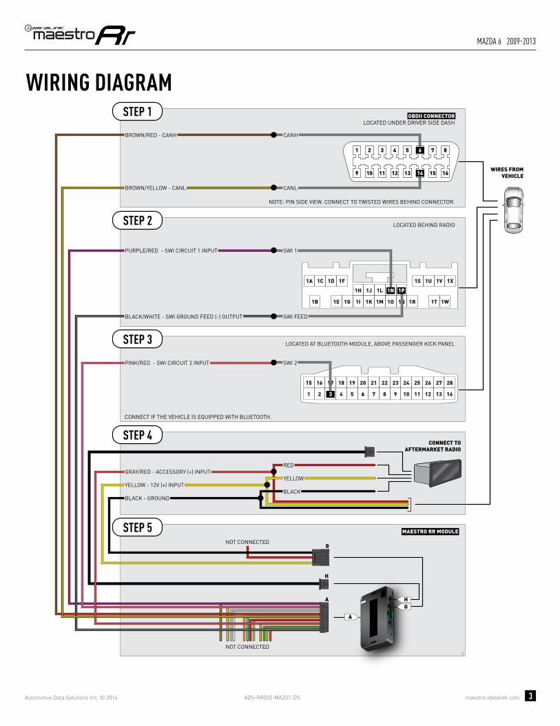
NOTE: PIN SIDE VIEW. CONNECT TO TWISTED WIRES BEHIND CONNECTOR.

ADS-RR(SI)-MAZ01-DS maestro.idatalink.com
Mazda 2 2011-2014
Automotive Data Solutions Inc. © 2014 4
VEHICLE WIRE REFERENCE CHART
WireDescription
Connector Name
ConnectorColor
ConnectorType Position Wire Color Polarity Wire
Location
CanH A ~ 16 pin 06 Red (DATA) OBDII connector, under driver side dash
CanL A ~ 16 pin 14 Blue (DATA) OBDII connector, under driver side dash
SWI 1 B ~ 24 pin 1N Red/Black (DATA) Behind radio
SWI Feed B ~ 24 pin 1P Green/White (-) Behind radio

OPTIONAL ACCESSORIESNone
PROGRAMMED FIRMWAREADS-RR(SI)-MAZ01-DS
PRODUCTS REQUIREDiDatalink Maestro RR Radio Replacement InterfaceiDatalink Compatible Radio
INSTALL GUIDEMAzDA 3
2004-2009retains steering wheel controls and adds gauges
NOTICE: Automotive Data Solutions Inc. (ADS) recommends having this installation performed by a certified technician. Logos and trademarks used here in are the properties of their respective owners.

ADS-RR(SI)-MAZ01-DS maestro.idatalink.com
Mazda 3 2004-2009
Automotive Data Solutions Inc. © 2014 2
WELCOME
NEED HELP?
Congratulations on the purchase of your iDatalink Maestro RR Radio replacement solution. You are now a few simple steps away from enjoying your new car radio with enhanced features. Before starting your installation, please ensure that your iDatalink Maestro module is programmed with the correct fi rmware for your vehicle and that you carefully review the install guide.
Please note that Maestro RR will only retain functionalities that were originally available in the vehicle.
1 866 427-2999
maestro.idatalink.com/supportwww.12voltdata.com/forum
TABLE OF CONTENTS
Wiring Diagram 3
Vehicle Wire Reference Chart 4

ADS-RR(SI)-MAZ01-DS maestro.idatalink.com
Mazda 3 2004-2009
Automotive Data Solutions Inc. © 2014 3
1I 1K1E1B 1G
1H
1Q 1R 1T 1W1M 1O
1N 1P1J 1L
1A 1F1C 1D 1S 1X1U 1V
A
HG
A
G
H
1
10 11 12 13 14 15 16
1 2 3 4 5 6 7 8
9
NOT CONNECTED
OBDII CONNECTORLOCATED UNDER DRIVER SIDE DASH
MAESTRO RR MODULE
CONNECT TOAFTERMARKET RADIO
PURPLE/RED - PURPLE/RED - SWI CIRCUIT 1 INPUT
LOCATED BEHIND RADIO
SWI 1SWI 1
SWI FEEDSWI FEEDBLACK/WHITE - BLACK/WHITE - SWI GROUND FEED (-) OUTPUT
WIRES FROMVEHICLE
WIRING DIAGRAMSTEP 1
STEP 2
STEP 3
STEP 4NOT CONNECTED
YELLOW - 12V (+) INPUT
BLACK - GROUND
GRAY/RED - ACCESSORY (+) INPUT
BLACKBLACK
REDRED
YELLOWYELLOW
BROWN/YELLOW - CANL
CANHCANH
CANLCANL
BROWN/RED - CANH
NOTE: PIN SIDE VIEW. CONNECT TO TWISTED WIRES BEHIND CONNECTOR.

ADS-RR(SI)-MAZ01-DS maestro.idatalink.com
Mazda 3 2004-2009
Automotive Data Solutions Inc. © 2014 4
VEHICLE WIRE REFERENCE CHART
WireDescription
Connector Name
ConnectorColor
ConnectorType Position Wire Color Polarity Wire
Location
CanH A ~ 16 pin 06 Gray/Yellow (DATA) OBDII connector, under driver side dash
CanL A ~ 16 pin 14 Blue/White (DATA) OBDII connector, under driver side dash
SWI 1 B ~ 24 pin 1N White/Black (DATA) Behind radio
SWI Feed B ~ 24 pin 1P Brown/Yellow (-) Behind radio

OPTIONAL ACCESSORIESNone
PROGRAMMED FIRMWAREADS-RR(SI)-MAZ01-DS
PRODUCTS REQUIREDiDatalink Maestro RR Radio Replacement InterfaceiDatalink Compatible Radio
INSTALL GUIDEMAzDA 3
2010-2013retains steering wheel controls and adds gauges
NOTICE: Automotive Data Solutions Inc. (ADS) recommends having this installation performed by a certified technician. Logos and trademarks used here in are the properties of their respective owners.
ADS-RR(SI)-MAZ01-DS maestro.idatalink.com
Mazda 3 2010-2013
Automotive Data Solutions Inc. © 2014 2
WELCOME
NEED HELP?
Congratulations on the purchase of your iDatalink Maestro RR Radio replacement solution. You are now a few simple steps away from enjoying your new car radio with enhanced features. Before starting your installation, please ensure that your iDatalink Maestro module is programmed with the correct fi rmware for your vehicle and that you carefully review the install guide.
Please note that Maestro RR will only retain functionalities that were originally available in the vehicle.
1 866 427-2999
maestro.idatalink.com/supportwww.12voltdata.com/forum
TABLE OF CONTENTS
Wiring Diagram 3
Vehicle Wire Reference Chart 4

ADS-RR(SI)-MAZ01-DS maestro.idatalink.com
Mazda 3 2010-2013
Automotive Data Solutions Inc. © 2014 3
1I 1K1E1B 1G
1H
1Q 1R 1T 1W1M 1O
1N 1P1J 1L
1A 1F1C 1D 1S 1X1U 1V
3 4 5 61 2
17 18 19 20
7 8
21 22 15 16
11 12 13 149 10
23 24 25 26 27 28
A
HG
A
G
H
2
10 11 12 13 14 15 16
1 2 3 4 5 6 7 8
9
NOT CONNECTED
OBDII CONNECTORLOCATED UNDER DRIVER SIDE DASH
MAESTRO RR MODULE
CONNECT TOAFTERMARKET RADIO
LOCATED BEHIND RADIO
SWI 1SWI 1
SWI FEEDSWI FEED
PURPLE/RED - PURPLE/RED - SWI CIRCUIT 1 INPUT
BLACK/WHITE - BLACK/WHITE - SWI GROUND FEED (-) OUTPUT
WIRES FROMVEHICLE
LOCATED AT BLUETOOTH MODULE, ABOVE PASSENGER KICK PANEL
SWI 2SWI 2PINK/RED - PINK/RED - SWI CIRCUIT 2 INPUT
WIRING DIAGRAMSTEP 1
STEP 2
STEP 3
STEP 5
STEP 4
CONNECT IF THE VEHICLE IS EQUIPPED WITH BLUETOOTH.
NOT CONNECTED
YELLOW - 12V (+) INPUT
BLACK - GROUND
GRAY/RED - ACCESSORY (+) INPUT
BLACKBLACK
REDRED
YELLOWYELLOW
BROWN/YELLOW - CANL
CANHCANH
CANLCANL
BROWN/RED - CANH
NOTE: PIN SIDE VIEW. CONNECT TO TWISTED WIRES BEHIND CONNECTOR.
ADS-RR(SI)-MAZ01-DS maestro.idatalink.com
Mazda 3 2010-2013
Automotive Data Solutions Inc. © 2014 4
VEHICLE WIRE REFERENCE CHART
WireDescription
Connector Name
ConnectorColor
ConnectorType Position Wire Color Polarity Wire
Location
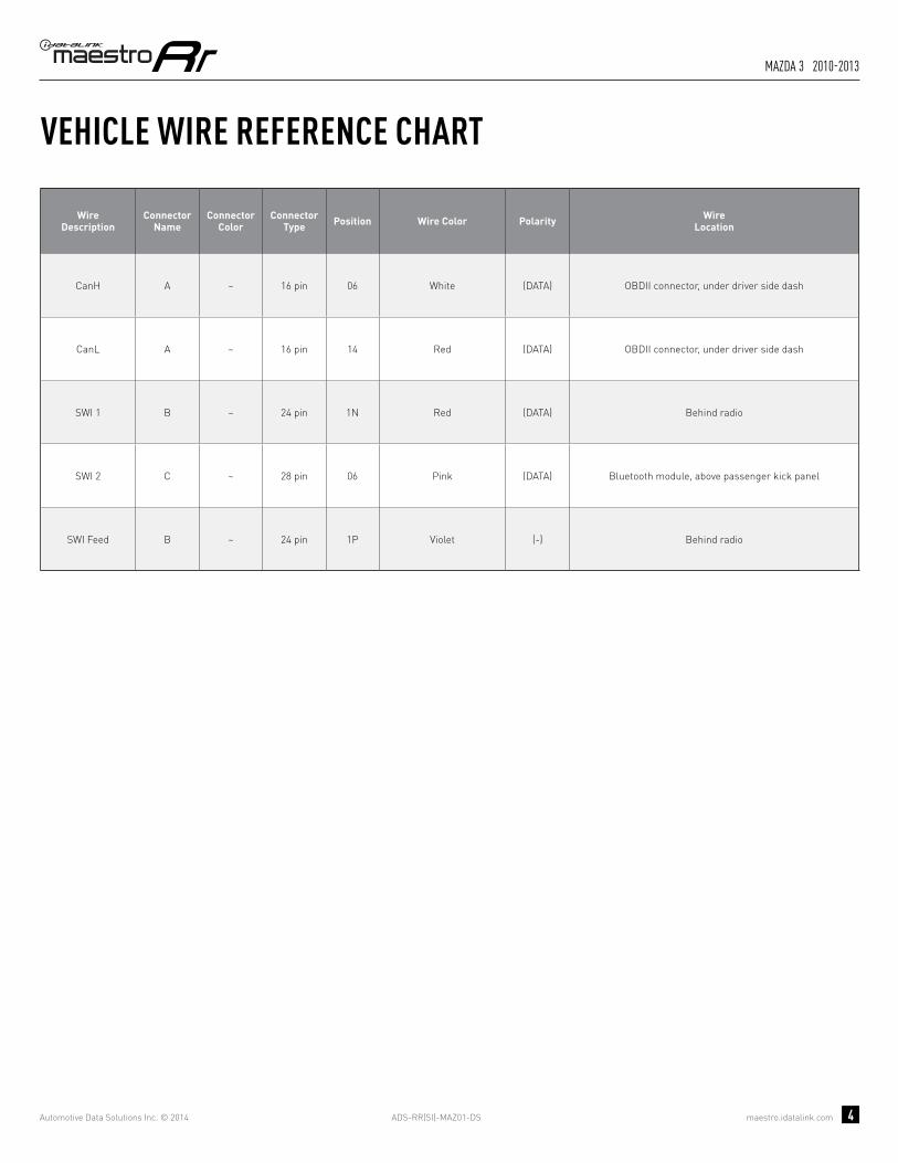
CanH A ~ 16 pin 06 White (DATA) OBDII connector, under driver side dash
CanL A ~ 16 pin 14 Red (DATA) OBDII connector, under driver side dash
SWI 1 B ~ 24 pin 1N Red (DATA) Behind radio
SWI 2 C ~ 28 pin 06 Pink (DATA) Bluetooth module, above passenger kick panel
SWI Feed B ~ 24 pin 1P Violet (-) Behind radio

OPTIONAL ACCESSORIESNone
PROGRAMMED FIRMWAREADS-RR(SI)-MAZ01-DS
PRODUCTS REQUIREDiDatalink Maestro RR Radio Replacement InterfaceiDatalink Compatible Radio
INSTALL GUIDEMAzDA 5
2006-2010retains steering wheel controls and adds gauges
NOTICE: Automotive Data Solutions Inc. (ADS) recommends having this installation performed by a certified technician. Logos and trademarks used here in are the properties of their respective owners.

ADS-RR(SI)-MAZ01-DS maestro.idatalink.com
Mazda 5 2006-2010
Automotive Data Solutions Inc. © 2014 2
WELCOME
NEED HELP?
Congratulations on the purchase of your iDatalink Maestro RR Radio replacement solution. You are now a few simple steps away from enjoying your new car radio with enhanced features. Before starting your installation, please ensure that your iDatalink Maestro module is programmed with the correct fi rmware for your vehicle and that you carefully review the install guide.
Please note that Maestro RR will only retain functionalities that were originally available in the vehicle.
1 866 427-2999
maestro.idatalink.com/supportwww.12voltdata.com/forum
TABLE OF CONTENTS
Wiring Diagram 3
Vehicle Wire Reference Chart 4

ADS-RR(SI)-MAZ01-DS maestro.idatalink.com
Mazda 5 2006-2010
Automotive Data Solutions Inc. © 2014 3
1I 1K1E1B 1G
1H
1Q 1R 1T 1W1M 1O
1N 1P1J 1L
1A 1F1C 1D 1S 1X1U 1V
A
HG
A
G
H
1
10 11 12 13 14 15 16
1 2 3 4 5 6 7 8
9
NOT CONNECTED
OBDII CONNECTORLOCATED UNDER DRIVER SIDE DASH
MAESTRO RR MODULE
CONNECT TOAFTERMARKET RADIO
PURPLE/RED - PURPLE/RED - SWI CIRCUIT 1 INPUT
LOCATED BEHIND RADIO
SWI 1SWI 1
SWI FEEDSWI FEEDBLACK/WHITE - BLACK/WHITE - SWI GROUND FEED (-) OUTPUT
WIRES FROMVEHICLE
WIRING DIAGRAMSTEP 1
STEP 2
STEP 3
STEP 4NOT CONNECTED
YELLOW - 12V (+) INPUT
BLACK - GROUND
GRAY/RED - ACCESSORY (+) INPUT
BLACKBLACK
REDRED
YELLOWYELLOW
BROWN/YELLOW - CANL
CANHCANH
CANLCANL
BROWN/RED - CANH
NOTE: PIN SIDE VIEW. CONNECT TO TWISTED WIRES BEHIND CONNECTOR.

ADS-RR(SI)-MAZ01-DS maestro.idatalink.com
Mazda 5 2006-2010
Automotive Data Solutions Inc. © 2014 4
VEHICLE WIRE REFERENCE CHART
WireDescription
Connector Name
ConnectorColor
ConnectorType Position Wire Color Polarity Wire
Location
CanH A ~ 16 pin 06 Red (DATA) OBDII connector, under driver side dash
CanL A ~ 16 pin 14 Blue or White (DATA) OBDII connector, under driver side dash
SWI 1 B ~ 24 pin 1N Red/Black (DATA) Behind radio
SWI Feed B ~ 24 pin 1P Green/White (-) Behind radio

OPTIONAL ACCESSORIESNone
PROGRAMMED FIRMWAREADS-RR(SI)-MAZ01-DS
PRODUCTS REQUIREDiDatalink Maestro RR Radio Replacement InterfaceiDatalink Compatible Radio
INSTALL GUIDEMAzDA 5
2011-2014retains steering wheel controls and adds gauges
NOTICE: Automotive Data Solutions Inc. (ADS) recommends having this installation performed by a certified technician. Logos and trademarks used here in are the properties of their respective owners.

ADS-RR(SI)-MAZ01-DS maestro.idatalink.com
Mazda 5 2011-2014
Automotive Data Solutions Inc. © 2014 2
WELCOME
NEED HELP?
Congratulations on the purchase of your iDatalink Maestro RR Radio replacement solution. You are now a few simple steps away from enjoying your new car radio with enhanced features. Before starting your installation, please ensure that your iDatalink Maestro module is programmed with the correct fi rmware for your vehicle and that you carefully review the install guide.
Please note that Maestro RR will only retain functionalities that were originally available in the vehicle.
1 866 427-2999
maestro.idatalink.com/supportwww.12voltdata.com/forum
TABLE OF CONTENTS
Wiring Diagram 3
Vehicle Wire Reference Chart 4

ADS-RR(SI)-MAZ01-DS maestro.idatalink.com
Mazda 5 2011-2014
Automotive Data Solutions Inc. © 2014 3
1I 1K1E1B 1G
1H
1Q 1R 1T 1W1M 1O
1N 1P1J 1L
1A 1F1C 1D 1S 1X1U 1V
A
HG
A
G
H
1
10 11 12 13 14 15 16
1 2 3 4 5 6 7 8
9
NOT CONNECTED
OBDII CONNECTORLOCATED UNDER DRIVER SIDE DASH
MAESTRO RR MODULE
CONNECT TOAFTERMARKET RADIO
PURPLE/RED - PURPLE/RED - SWI CIRCUIT 1 INPUT
LOCATED BEHIND RADIO
SWI 1SWI 1
SWI FEEDSWI FEEDBLACK/WHITE - BLACK/WHITE - SWI GROUND FEED (-) OUTPUT
WIRES FROMVEHICLE
WIRING DIAGRAMSTEP 1
STEP 2
STEP 3
STEP 4NOT CONNECTED
YELLOW - 12V (+) INPUT
BLACK - GROUND
GRAY/RED - ACCESSORY (+) INPUT
BLACKBLACK
REDRED
YELLOWYELLOW
BROWN/YELLOW - CANL
CANHCANH
CANLCANL
BROWN/RED - CANH
NOTE: PIN SIDE VIEW. CONNECT TO TWISTED WIRES BEHIND CONNECTOR.

ADS-RR(SI)-MAZ01-DS maestro.idatalink.com
Mazda 5 2011-2014
Automotive Data Solutions Inc. © 2014 4
VEHICLE WIRE REFERENCE CHART
WireDescription
Connector Name
ConnectorColor
ConnectorType Position Wire Color Polarity Wire
Location
CanH A ~ 16 pin 06 Green/Yellow (DATA) OBDII connector, under driver side dash
CanL A ~ 16 pin 14 Red/Yellow (DATA) OBDII connector, under driver side dash
SWI 1 B ~ 24 pin 1N Black/Red (DATA) Behind radio
SWI Feed B ~ 24 pin 1P Green/Black (-) Behind radio

OPTIONAL ACCESSORIESNone
PROGRAMMED FIRMWAREADS-RR(SI)-MAZ01-DS
PRODUCTS REQUIREDiDatalink Maestro RR Radio Replacement InterfaceiDatalink Compatible Radio
INSTALL GUIDEMAzDA 6
2004-2008retains steering wheel controls and adds gauges
NOTICE: Automotive Data Solutions Inc. (ADS) recommends having this installation performed by a certified technician. Logos and trademarks used here in are the properties of their respective owners.

ADS-RR(SI)-MAZ01-DS maestro.idatalink.com
Mazda 6 2004-2008
Automotive Data Solutions Inc. © 2014 2
WELCOME
NEED HELP?
Congratulations on the purchase of your iDatalink Maestro RR Radio replacement solution. You are now a few simple steps away from enjoying your new car radio with enhanced features. Before starting your installation, please ensure that your iDatalink Maestro module is programmed with the correct fi rmware for your vehicle and that you carefully review the install guide.
Please note that Maestro RR will only retain functionalities that were originally available in the vehicle.
1 866 427-2999
maestro.idatalink.com/supportwww.12voltdata.com/forum
TABLE OF CONTENTS
Wiring Diagram 3
Vehicle Wire Reference Chart 4

ADS-RR(SI)-MAZ01-DS maestro.idatalink.com
Mazda 6 2004-2008
Automotive Data Solutions Inc. © 2014 3
1I 1K1E1B 1G
1H
1Q 1R 1T 1W1M 1O
1N 1P1J 1L
1A 1F1C 1D 1S 1X1U 1V
A
HG
A
G
H
1
10 11 12 13 14 15 16
1 2 3 4 5 6 7 8
9
NOT CONNECTED
OBDII CONNECTORLOCATED UNDER DRIVER SIDE DASH
MAESTRO RR MODULE
CONNECT TOAFTERMARKET RADIO
PURPLE/RED - PURPLE/RED - SWI CIRCUIT 1 INPUT
LOCATED BEHIND RADIO
SWI 1SWI 1
SWI FEEDSWI FEEDBLACK/WHITE - BLACK/WHITE - SWI GROUND FEED (-) OUTPUT
WIRES FROMVEHICLE
WIRING DIAGRAMSTEP 1
STEP 2
STEP 3
STEP 4NOT CONNECTED
YELLOW - 12V (+) INPUT
BLACK - GROUND
GRAY/RED - ACCESSORY (+) INPUT
BLACKBLACK
REDRED
YELLOWYELLOW
BROWN/YELLOW - CANL
CANHCANH
CANLCANL
BROWN/RED - CANH
NOTE: PIN SIDE VIEW. CONNECT TO TWISTED WIRES BEHIND CONNECTOR.

ADS-RR(SI)-MAZ01-DS maestro.idatalink.com
Mazda 6 2004-2008
Automotive Data Solutions Inc. © 2014 4
VEHICLE WIRE REFERENCE CHART
WireDescription
Connector Name
ConnectorColor
ConnectorType Position Wire Color Polarity Wire
Location
CanH A ~ 16 pin 06 Red (DATA) OBDII connector, under driver side dash
CanL A ~ 16 pin 14 Blue (DATA) OBDII connector, under driver side dash
SWI 1 B ~ 24 pin 1N Red/Black (DATA) Behind radio
SWI Feed B ~ 24 pin 1P Green/White (-) Behind radio

OPTIONAL ACCESSORIESNone
PROGRAMMED FIRMWAREADS-RR(SI)-MAZ01-DS
PRODUCTS REQUIREDiDatalink Maestro RR Radio Replacement InterfaceiDatalink Compatible Radio
INSTALL GUIDEMAzDA 6
2009-2013retains steering wheel controls and adds gauges
NOTICE: Automotive Data Solutions Inc. (ADS) recommends having this installation performed by a certified technician. Logos and trademarks used here in are the properties of their respective owners.

ADS-RR(SI)-MAZ01-DS maestro.idatalink.com
Mazda 6 2009-2013
Automotive Data Solutions Inc. © 2014 2
WELCOME
NEED HELP?
Congratulations on the purchase of your iDatalink Maestro RR Radio replacement solution. You are now a few simple steps away from enjoying your new car radio with enhanced features. Before starting your installation, please ensure that your iDatalink Maestro module is programmed with the correct fi rmware for your vehicle and that you carefully review the install guide.
Please note that Maestro RR will only retain functionalities that were originally available in the vehicle.
1 866 427-2999
maestro.idatalink.com/supportwww.12voltdata.com/forum
TABLE OF CONTENTS
Wiring Diagram 3
Vehicle Wire Reference Chart 4
ADS-RR(SI)-MAZ01-DS maestro.idatalink.com
Mazda 6 2009-2013
Automotive Data Solutions Inc. © 2014 3
1I 1K1E1B 1G
1H
1Q 1R 1T 1W1M 1O
1N 1P1J 1L
1A 1F1C 1D 1S 1X1U 1V
3 4 5 61 2
17 18 19 20
7 8
21 22 15 16
11 12 13 149 10
23 24 25 26 27 28
A
HG
A
G
H
2
10 11 12 13 14 15 16
1 2 3 4 5 6 7 8
9
NOT CONNECTED
OBDII CONNECTORLOCATED UNDER DRIVER SIDE DASH
MAESTRO RR MODULE
CONNECT TOAFTERMARKET RADIO
LOCATED BEHIND RADIO
SWI 1SWI 1
SWI FEEDSWI FEED
PURPLE/RED - PURPLE/RED - SWI CIRCUIT 1 INPUT
BLACK/WHITE - BLACK/WHITE - SWI GROUND FEED (-) OUTPUT
WIRES FROMVEHICLE
LOCATED AT BLUETOOTH MODULE, ABOVE PASSENGER KICK PANEL
SWI 2SWI 2PINK/RED - PINK/RED - SWI CIRCUIT 2 INPUT
WIRING DIAGRAMSTEP 1
STEP 2
STEP 3
STEP 5
STEP 4
CONNECT IF THE VEHICLE IS EQUIPPED WITH BLUETOOTH.
NOT CONNECTED
YELLOW - 12V (+) INPUT
BLACK - GROUND
GRAY/RED - ACCESSORY (+) INPUT
BLACKBLACK
REDRED
YELLOWYELLOW
BROWN/YELLOW - CANL
CANHCANH
CANLCANL
BROWN/RED - CANH
NOTE: PIN SIDE VIEW. CONNECT TO TWISTED WIRES BEHIND CONNECTOR.

ADS-RR(SI)-MAZ01-DS maestro.idatalink.com
Mazda 6 2009-2013
Automotive Data Solutions Inc. © 2014 4
VEHICLE WIRE REFERENCE CHART
WireDescription
Connector Name
ConnectorColor
ConnectorType Position Wire Color Polarity Wire
Location
CanH A ~ 16 pin 06 Gray/Red (DATA) OBDII connector, under driver side dash
CanL A ~ 16 pin 14 Blue/Red (DATA) OBDII connector, under driver side dash
SWI 1 B ~ 24 pin 1N White/Black (DATA) Behind radio
SWI 2 C ~ 28 pin 06 White/Red (DATA) Bluetooth module, above passenger kick panel
SWI Feed B ~ 24 pin 1P Brown/Yellow (-) Behind radio

OPTIONAL ACCESSORIESNone
PROGRAMMED FIRMWAREADS-RR(SI)-MAZ01-DS
PRODUCTS REQUIREDiDatalink Maestro RR Radio Replacement InterfaceiDatalink Compatible Radio
INSTALL GUIDEMAzDA CX-7 2007-2009
retains steering wheel controls and adds gauges
NOTICE: Automotive Data Solutions Inc. (ADS) recommends having this installation performed by a certified technician. Logos and trademarks used here in are the properties of their respective owners.

ADS-RR(SI)-MAZ01-DS maestro.idatalink.com
Mazda cX-7 2007-2009
Automotive Data Solutions Inc. © 2014 2
WELCOME
NEED HELP?
Congratulations on the purchase of your iDatalink Maestro RR Radio replacement solution. You are now a few simple steps away from enjoying your new car radio with enhanced features. Before starting your installation, please ensure that your iDatalink Maestro module is programmed with the correct fi rmware for your vehicle and that you carefully review the install guide.
Please note that Maestro RR will only retain functionalities that were originally available in the vehicle.
1 866 427-2999
maestro.idatalink.com/supportwww.12voltdata.com/forum
TABLE OF CONTENTS
Wiring Diagram 3
Vehicle Wire Reference Chart 4

ADS-RR(SI)-MAZ01-DS maestro.idatalink.com
Mazda cX-7 2007-2009
Automotive Data Solutions Inc. © 2014 3
1I 1K1E1B 1G
1H
1Q 1R 1T 1W1M 1O
1N 1P1J 1L
1A 1F1C 1D 1S 1X1U 1V
A
HG
A
G
H
1
10 11 12 13 14 15 16
1 2 3 4 5 6 7 8
9
NOT CONNECTED
OBDII CONNECTORLOCATED UNDER DRIVER SIDE DASH
MAESTRO RR MODULE
CONNECT TOAFTERMARKET RADIO
PURPLE/RED - PURPLE/RED - SWI CIRCUIT 1 INPUT
LOCATED BEHIND RADIO
SWI 1SWI 1
SWI FEEDSWI FEEDBLACK/WHITE - BLACK/WHITE - SWI GROUND FEED (-) OUTPUT
WIRES FROMVEHICLE
WIRING DIAGRAMSTEP 1
STEP 2
STEP 3
STEP 4NOT CONNECTED
YELLOW - 12V (+) INPUT
BLACK - GROUND
GRAY/RED - ACCESSORY (+) INPUT
BLACKBLACK
REDRED
YELLOWYELLOW
BROWN/YELLOW - CANL
CANHCANH
CANLCANL
BROWN/RED - CANH
NOTE: PIN SIDE VIEW. CONNECT TO TWISTED WIRES BEHIND CONNECTOR.

ADS-RR(SI)-MAZ01-DS maestro.idatalink.com
Mazda cX-7 2007-2009
Automotive Data Solutions Inc. © 2014 4
VEHICLE WIRE REFERENCE CHART
WireDescription
Connector Name
ConnectorColor
ConnectorType Position Wire Color Polarity Wire
Location
CanH A ~ 16 pin 06 Gray/Violet (DATA) OBDII connector, under driver side dash
CanL A ~ 16 pin 14 Blue/White (DATA) OBDII connector, under driver side dash
SWI 1 B ~ 24 pin 1N White/Black (DATA) Behind radio
SWI Feed B ~ 24 pin 1P Brown/Yellow (-) Behind radio

OPTIONAL ACCESSORIESNone
PROGRAMMED FIRMWAREADS-RR(SI)-MAZ01-DS
PRODUCTS REQUIREDiDatalink Maestro RR Radio Replacement InterfaceiDatalink Compatible Radio
INSTALL GUIDEMAzDA CX-7 2010-2012
retains steering wheel controls and adds gauges
NOTICE: Automotive Data Solutions Inc. (ADS) recommends having this installation performed by a certified technician. Logos and trademarks used here in are the properties of their respective owners.

ADS-RR(SI)-MAZ01-DS maestro.idatalink.com
Mazda cX-7 2010-2012
Automotive Data Solutions Inc. © 2014 2
WELCOME
NEED HELP?
Congratulations on the purchase of your iDatalink Maestro RR Radio replacement solution. You are now a few simple steps away from enjoying your new car radio with enhanced features. Before starting your installation, please ensure that your iDatalink Maestro module is programmed with the correct fi rmware for your vehicle and that you carefully review the install guide.
Please note that Maestro RR will only retain functionalities that were originally available in the vehicle.
1 866 427-2999
maestro.idatalink.com/supportwww.12voltdata.com/forum
TABLE OF CONTENTS
Wiring Diagram 3
Vehicle Wire Reference Chart 4

ADS-RR(SI)-MAZ01-DS maestro.idatalink.com
Mazda cX-7 2010-2012
Automotive Data Solutions Inc. © 2014 3
1I 1K1E1B 1G
1H
1Q 1R 1T 1W1M 1O
1N 1P1J 1L
1A 1F1C 1D 1S 1X1U 1V
3 4 5 61 2
17 18 19 20
7 8
21 22 15 16
11 12 13 149 10
23 24 25 26 27 28
A
HG
A
G
H
2
10 11 12 13 14 15 16
1 2 3 4 5 6 7 8
9
NOT CONNECTED
OBDII CONNECTORLOCATED UNDER DRIVER SIDE DASH
MAESTRO RR MODULE
CONNECT TOAFTERMARKET RADIO
LOCATED BEHIND RADIO
SWI 1SWI 1
SWI FEEDSWI FEED
PURPLE/RED - PURPLE/RED - SWI CIRCUIT 1 INPUT
BLACK/WHITE - BLACK/WHITE - SWI GROUND FEED (-) OUTPUT
WIRES FROMVEHICLE
LOCATED AT BLUETOOTH MODULE, ABOVE PASSENGER KICK PANEL
SWI 2SWI 2PINK/RED - PINK/RED - SWI CIRCUIT 2 INPUT
WIRING DIAGRAMSTEP 1
STEP 2
STEP 3
STEP 5
STEP 4
CONNECT IF THE VEHICLE IS EQUIPPED WITH BLUETOOTH.
NOT CONNECTED
YELLOW - 12V (+) INPUT
BLACK - GROUND
GRAY/RED - ACCESSORY (+) INPUT
BLACKBLACK
REDRED
YELLOWYELLOW
BROWN/YELLOW - CANL
CANHCANH
CANLCANL
BROWN/RED - CANH
NOTE: PIN SIDE VIEW. CONNECT TO TWISTED WIRES BEHIND CONNECTOR.

ADS-RR(SI)-MAZ01-DS maestro.idatalink.com
Mazda cX-7 2010-2012
Automotive Data Solutions Inc. © 2014 4
VEHICLE WIRE REFERENCE CHART
WireDescription
Connector Name
ConnectorColor
ConnectorType Position Wire Color Polarity Wire
Location
CanH A ~ 16 pin 06 Gray/DkBlue (DATA) OBDII connector, under driver side dash
CanL A ~ 16 pin 14 DkBlue/White (DATA) OBDII connector, under driver side dash
SWI 1 B ~ 24 pin 1N White/Black (DATA) Behind radio
SWI 2 C ~ 28 pin 06 Brown (DATA) Bluetooth module, above passenger kick panel
SWI Feed B ~ 24 pin 1P Brown/Yellow (-) Behind radio

OPTIONAL ACCESSORIESNone
PROGRAMMED FIRMWAREADS-RR(SI)-MAZ01-DS
PRODUCTS REQUIREDiDatalink Maestro RR Radio Replacement InterfaceiDatalink Compatible Radio
INSTALL GUIDEMAzDA CX-9 2007-2014
retains steering wheel controls and adds gauges
NOTICE: Automotive Data Solutions Inc. (ADS) recommends having this installation performed by a certified technician. Logos and trademarks used here in are the properties of their respective owners.

ADS-RR(SI)-MAZ01-DS maestro.idatalink.com
Mazda cX-9 2007-2014
Automotive Data Solutions Inc. © 2014 2
WELCOME
NEED HELP?
Congratulations on the purchase of your iDatalink Maestro RR Radio replacement solution. You are now a few simple steps away from enjoying your new car radio with enhanced features. Before starting your installation, please ensure that your iDatalink Maestro module is programmed with the correct fi rmware for your vehicle and that you carefully review the install guide.
Please note that Maestro RR will only retain functionalities that were originally available in the vehicle.
1 866 427-2999
maestro.idatalink.com/supportwww.12voltdata.com/forum
TABLE OF CONTENTS
Wiring Diagram 3
Vehicle Wire Reference Chart 4

ADS-RR(SI)-MAZ01-DS maestro.idatalink.com
Mazda cX-9 2007-2014
Automotive Data Solutions Inc. © 2014 3
1I 1K1E1B 1G
1H
1Q 1R 1T 1W1M 1O
1N 1P1J 1L
1A 1F1C 1D 1S 1X1U 1V
3 4 5 61 2
17 18 19 20
7 8
21 22 15 16
11 12 13 149 10
23 24 25 26 27 28
A
HG
A
G
H
2
10 11 12 13 14 15 16
1 2 3 4 5 6 7 8
9
NOT CONNECTED
OBDII CONNECTORLOCATED UNDER DRIVER SIDE DASH
MAESTRO RR MODULE
CONNECT TOAFTERMARKET RADIO
LOCATED BEHIND RADIO
SWI 1SWI 1
SWI FEEDSWI FEED
PURPLE/RED - PURPLE/RED - SWI CIRCUIT 1 INPUT
BLACK/WHITE - BLACK/WHITE - SWI GROUND FEED (-) OUTPUT
WIRES FROMVEHICLE
LOCATED AT BLUETOOTH MODULE, ABOVE PASSENGER KICK PANEL
SWI 2SWI 2PINK/RED - PINK/RED - SWI CIRCUIT 2 INPUT
WIRING DIAGRAMSTEP 1
STEP 2
STEP 3
STEP 5
STEP 4
CONNECT IF THE VEHICLE IS EQUIPPED WITH BLUETOOTH.
NOT CONNECTED
YELLOW - 12V (+) INPUT
BLACK - GROUND
GRAY/RED - ACCESSORY (+) INPUT
BLACKBLACK
REDRED
YELLOWYELLOW
BROWN/YELLOW - CANL
CANHCANH
CANLCANL
BROWN/RED - CANH
NOTE: PIN SIDE VIEW. CONNECT TO TWISTED WIRES BEHIND CONNECTOR.

ADS-RR(SI)-MAZ01-DS maestro.idatalink.com
Mazda cX-9 2007-2014
Automotive Data Solutions Inc. © 2014 4
VEHICLE WIRE REFERENCE CHART
WireDescription
Connector Name
ConnectorColor
ConnectorType Position Wire Color Polarity Wire
Location
CanH A ~ 16 pin 06 Red (DATA) OBDII connector, under driver side dash
CanL A ~ 16 pin 14 Blue (DATA) OBDII connector, under driver side dash
SWI 1 B ~ 24 pin 1N Gray/Black (DATA) Behind radio
SWI 2 C ~ 28 pin 06 LtGreen/Red (DATA) Bluetooth module, above passenger kick panel
SWI Feed B ~ 24 pin 1P White/Red (-) Behind radio

OPTIONAL ACCESSORIESNone
PROGRAMMED FIRMWAREADS-RR(SI)-MAZ01-DS
PRODUCTS REQUIREDiDatalink Maestro RR Radio Replacement InterfaceiDatalink Compatible Radio
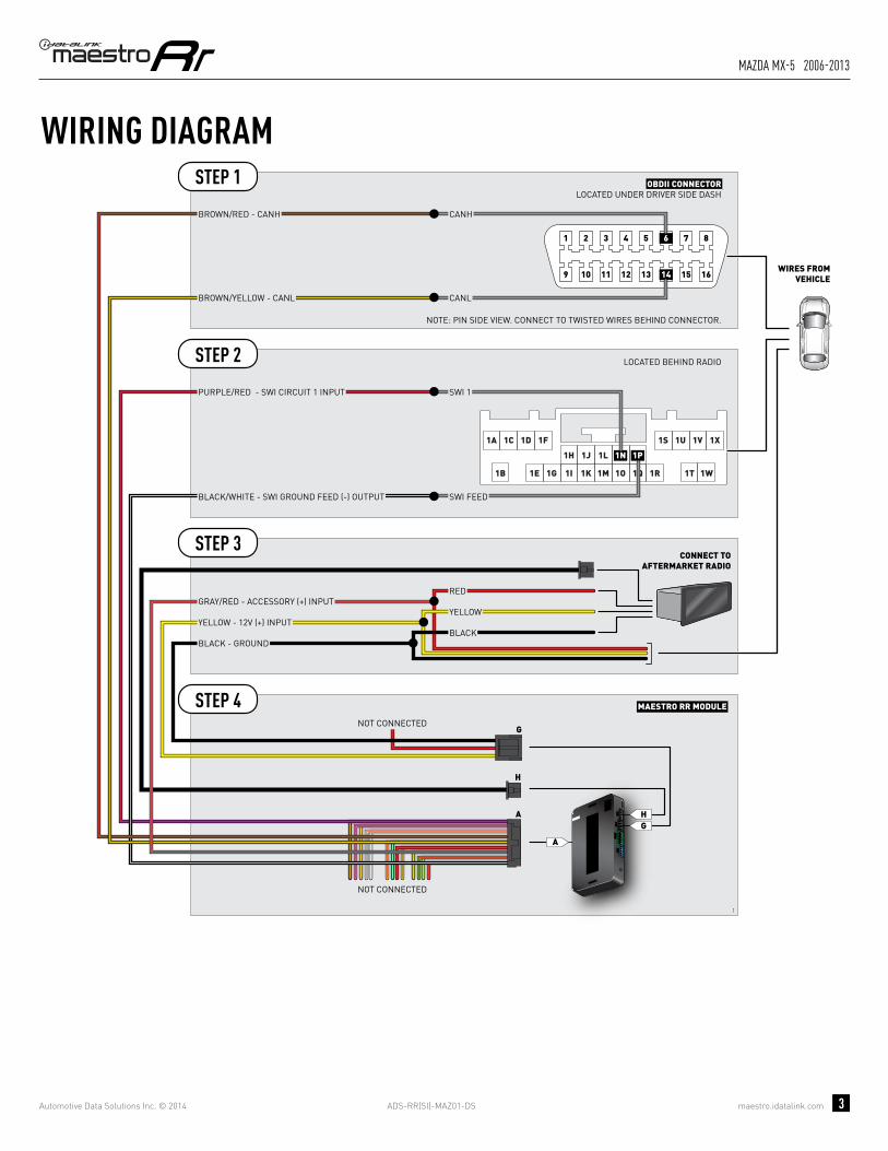
INSTALL GUIDEMAzDA MX-5 2006-2013
retains steering wheel controls and adds gauges
NOTICE: Automotive Data Solutions Inc. (ADS) recommends having this installation performed by a certified technician. Logos and trademarks used here in are the properties of their respective owners.

ADS-RR(SI)-MAZ01-DS maestro.idatalink.com
Mazda MX-5 2006-2013
Automotive Data Solutions Inc. © 2014 2
WELCOME
NEED HELP?
Congratulations on the purchase of your iDatalink Maestro RR Radio replacement solution. You are now a few simple steps away from enjoying your new car radio with enhanced features. Before starting your installation, please ensure that your iDatalink Maestro module is programmed with the correct fi rmware for your vehicle and that you carefully review the install guide.
Please note that Maestro RR will only retain functionalities that were originally available in the vehicle.
1 866 427-2999
maestro.idatalink.com/supportwww.12voltdata.com/forum
TABLE OF CONTENTS
Wiring Diagram 3
Vehicle Wire Reference Chart 4
ADS-RR(SI)-MAZ01-DS maestro.idatalink.com
Mazda MX-5 2006-2013
Automotive Data Solutions Inc. © 2014 3
1I 1K1E1B 1G
1H
1Q 1R 1T 1W1M 1O
1N 1P1J 1L
1A 1F1C 1D 1S 1X1U 1V
A
HG
A
G
H
1
10 11 12 13 14 15 16
1 2 3 4 5 6 7 8
9
NOT CONNECTED
OBDII CONNECTORLOCATED UNDER DRIVER SIDE DASH
MAESTRO RR MODULE
CONNECT TOAFTERMARKET RADIO
PURPLE/RED - PURPLE/RED - SWI CIRCUIT 1 INPUT
LOCATED BEHIND RADIO
SWI 1SWI 1
SWI FEEDSWI FEEDBLACK/WHITE - BLACK/WHITE - SWI GROUND FEED (-) OUTPUT
WIRES FROMVEHICLE
WIRING DIAGRAMSTEP 1
STEP 2
STEP 3
STEP 4NOT CONNECTED
YELLOW - 12V (+) INPUT
BLACK - GROUND
GRAY/RED - ACCESSORY (+) INPUT
BLACKBLACK
REDRED
YELLOWYELLOW
BROWN/YELLOW - CANL
CANHCANH
CANLCANL
BROWN/RED - CANH
NOTE: PIN SIDE VIEW. CONNECT TO TWISTED WIRES BEHIND CONNECTOR.

ADS-RR(SI)-MAZ01-DS maestro.idatalink.com
Mazda MX-5 2006-2013
Automotive Data Solutions Inc. © 2014 4
VEHICLE WIRE REFERENCE CHART
WireDescription
Connector Name
ConnectorColor
ConnectorType Position Wire Color Polarity Wire
Location
CanH A ~ 16 pin 06 Blue/White (DATA) OBDII connector, under driver side dash
CanL A ~ 16 pin 14 Green/Black (DATA) OBDII connector, under driver side dash
SWI 1 B ~ 24 pin 1N Blue/Black (DATA) Behind radio
SWI Feed B ~ 24 pin 1P Green/White (-) Behind radio

OPTIONAL ACCESSORIESNone
PROGRAMMED FIRMWAREADS-RR(SI)-MAZ01-DS
PRODUCTS REQUIREDiDatalink Maestro RR Radio Replacement InterfaceiDatalink Compatible Radio
INSTALL GUIDEMAzDA RX-8 2004-2012
retains steering wheel controls and adds gauges
NOTICE: Automotive Data Solutions Inc. (ADS) recommends having this installation performed by a certified technician. Logos and trademarks used here in are the properties of their respective owners.

ADS-RR(SI)-MAZ01-DS maestro.idatalink.com
Mazda rX-8 2004-2012
Automotive Data Solutions Inc. © 2014 2
WELCOME
NEED HELP?
Congratulations on the purchase of your iDatalink Maestro RR Radio replacement solution. You are now a few simple steps away from enjoying your new car radio with enhanced features. Before starting your installation, please ensure that your iDatalink Maestro module is programmed with the correct fi rmware for your vehicle and that you carefully review the install guide.
Please note that Maestro RR will only retain functionalities that were originally available in the vehicle.
1 866 427-2999
maestro.idatalink.com/supportwww.12voltdata.com/forum
TABLE OF CONTENTS
Wiring Diagram 3
Vehicle Wire Reference Chart 4

ADS-RR(SI)-MAZ01-DS maestro.idatalink.com
Mazda rX-8 2004-2012
Automotive Data Solutions Inc. © 2014 3
1I 1K1E1B 1G
1H
1Q 1R 1T 1W1M 1O
1N 1P1J 1L
1A 1F1C 1D 1S 1X1U 1V
A
HG
A
G
H
1
10 11 12 13 14 15 16
1 2 3 4 5 6 7 8
9
NOT CONNECTED
OBDII CONNECTORLOCATED UNDER DRIVER SIDE DASH
MAESTRO RR MODULE
CONNECT TOAFTERMARKET RADIO
PURPLE/RED - PURPLE/RED - SWI CIRCUIT 1 INPUT
LOCATED BEHIND RADIO
SWI 1SWI 1
SWI FEEDSWI FEEDBLACK/WHITE - BLACK/WHITE - SWI GROUND FEED (-) OUTPUT
WIRES FROMVEHICLE
WIRING DIAGRAMSTEP 1
STEP 2
STEP 3
STEP 4NOT CONNECTED
YELLOW - 12V (+) INPUT
BLACK - GROUND
GRAY/RED - ACCESSORY (+) INPUT
BLACKBLACK
REDRED
YELLOWYELLOW
BROWN/YELLOW - CANL
CANHCANH
CANLCANL
BROWN/RED - CANH
NOTE: PIN SIDE VIEW. CONNECT TO TWISTED WIRES BEHIND CONNECTOR.

ADS-RR(SI)-MAZ01-DS maestro.idatalink.com
Mazda rX-8 2004-2012
Automotive Data Solutions Inc. © 2014 4
VEHICLE WIRE REFERENCE CHART
WireDescription
Connector Name
ConnectorColor
ConnectorType Position Wire Color Polarity Wire
Location
CanH A ~ 16 pin 06 Blue/White (DATA) OBDII connector, under driver side dash
CanL A ~ 16 pin 14 Green/Black (DATA) OBDII connector, under driver side dash
SWI 1 B ~ 24 pin 1N Red/Black (DATA) Behind radio
SWI Feed B ~ 24 pin 1P Green/White (-) Behind radio