hp adjustable depth fixed rail kit...
TRANSCRIPT

HP Adjustable Depth Fixed Rail Kit Installation
IntroductionThis installation guide explains how to install the HP Adjustable Depth Fixed Rail Kit on an HP Z6 G4, HP Z4 G4, or HP Z2 G5 series workstation and then install the workstation into a rack.
Kit contents
NOTE: Kit contents might vary depending on your computer model.
• Rack mount tray
• Fixed rails (2)
• System retainer brackets (2)
• #6-32 x 1/2” Phillips flathead screws (2)
• #10-32 x 1/2” Phillips Trusshead screws (12)
• Installation instructions (this document)
• Warranty information
Before you beginTo view QuickSpecs and determine the compatibility of this product with your HP computer, see http://www.hp.com/go/productbulletin.
Tools required• #2 Phillips screwdriver
L10617-001.fm Page 1 Monday, September 25, 2017 2:30 PM
2 HP Adjustable Depth Fixed Rail Kit Installation
Warnings and cautions
WARNING! Any surface or area of the equipment marked with this symbol indicates the presence of a hot surface or hot component. If this surface is contacted, the potential for injury exists. To reduce the risk of injury from a hot component, enable the surface to cool before touching.
WARNING! Any surface or area of the equipment marked with this symbol indicates the presence of an electrical shock hazard. To reduce the risk of injury from electrical shock, do not open any enclosed area marked with this symbol.
WARNING! To reduce the risk of electric shock or damage to your equipment:- Do not disable the power cord grounding plug. The grounding plug is an important safety feature.- Plug the power cord in a grounded (earthed) outlet that is easily accessible at all times.- Disconnect power from the equipment by unplugging the power cord from the electrical outlet.
WARNING! To reduce the risk of serious injury, read the Safety & Comfort Guide. It describes the proper computer setup, posture, health, and work habits for computer users, and provides important electrical and mechanical safety information. This guide is located at http://www.hp.com/ergo and on the documentation CD (if one is included with the product).
WARNING! If a product is shipped in packaging marked with this symbol, , the product must always be lifted by two persons to avoid personal injury due to product weight.
CAUTION: Static electricity can damage the electronic components of the computer. Before beginning these procedures, be sure you discharge static electricity by briefly touching a grounded metal object.
CAUTION: To prevent damage to the computer, observe the following Electrostatic Discharge (ESD) precautions while performing the system parts removal and replacement procedures.
- Work on a static-free mat.- Wear a static strap to ensure that any accumulated electrostatic charge is discharged from your body
to the ground.- Create a common ground for the equipment you are working on by connecting the static-free mat,
static strap, and peripheral units to that piece of equipment.
NOTE: HP accessories are for use in HP computer products. They have been extensively tested for reliability and are manufactured to high quality standards.
L10617-001.fm Page 2 Monday, September 25, 2017 2:30 PM
HP Adjustable Depth Fixed Rail Kit Installation 3
Step 1—Accessing the internal components of the computer1. If you need help preparing the computer for this installation, consult the removal and replacement
procedures in the HP Customer Self Repair Services Media Library at http://www.hp.com/go/sml.
2. Power down the workstation, and then disconnect the power cord.
3. Power down all external devices, and then disconnect them from the computer.
Step 2—Installing the rails
NOTE: For safety reasons, HP recommends loading the rack from the bottom up. Secure rails at the bottom of the rack first.
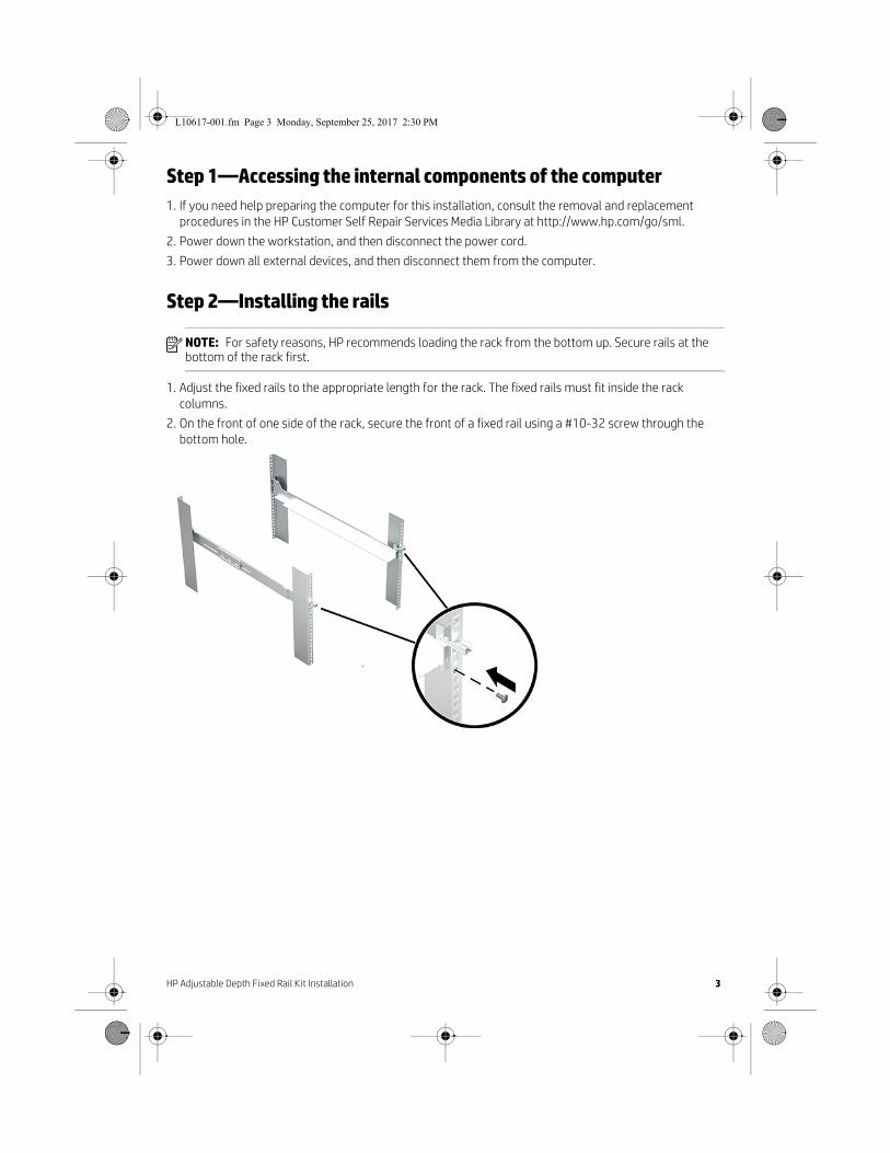
1. Adjust the fixed rails to the appropriate length for the rack. The fixed rails must fit inside the rack columns.
2. On the front of one side of the rack, secure the front of a fixed rail using a #10-32 screw through the bottom hole.
L10617-001.fm Page 3 Monday, September 25, 2017 2:30 PM
4 HP Adjustable Depth Fixed Rail Kit Installation
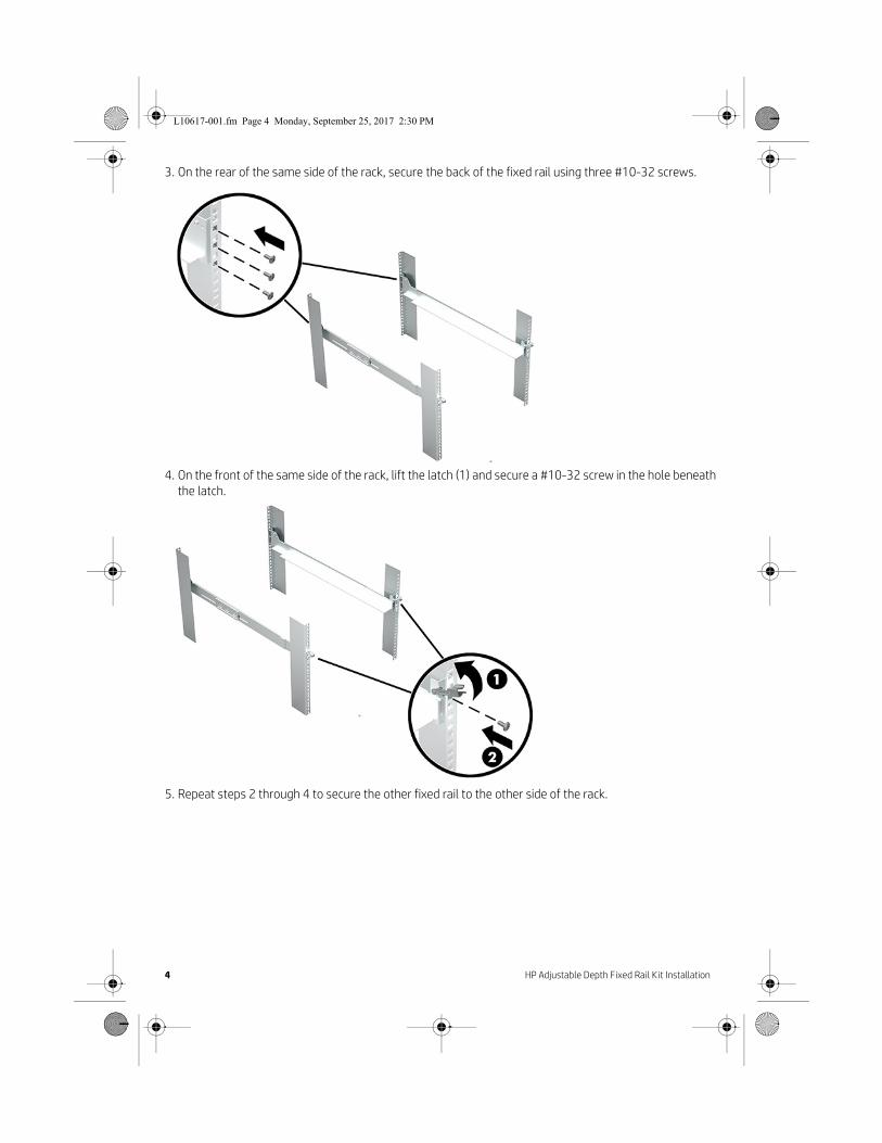
3. On the rear of the same side of the rack, secure the back of the fixed rail using three #10-32 screws.
4. On the front of the same side of the rack, lift the latch (1) and secure a #10-32 screw in the hole beneath the latch.
5. Repeat steps 2 through 4 to secure the other fixed rail to the other side of the rack.
L10617-001.fm Page 4 Monday, September 25, 2017 2:30 PM
HP Adjustable Depth Fixed Rail Kit Installation 5
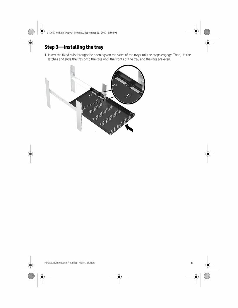
Step 3—Installing the tray1. Insert the fixed rails through the openings on the sides of the tray until the stops engage. Then, lift the
latches and slide the tray onto the rails until the fronts of the tray and the rails are even.
L10617-001.fm Page 5 Monday, September 25, 2017 2:30 PM
6 HP Adjustable Depth Fixed Rail Kit Installation
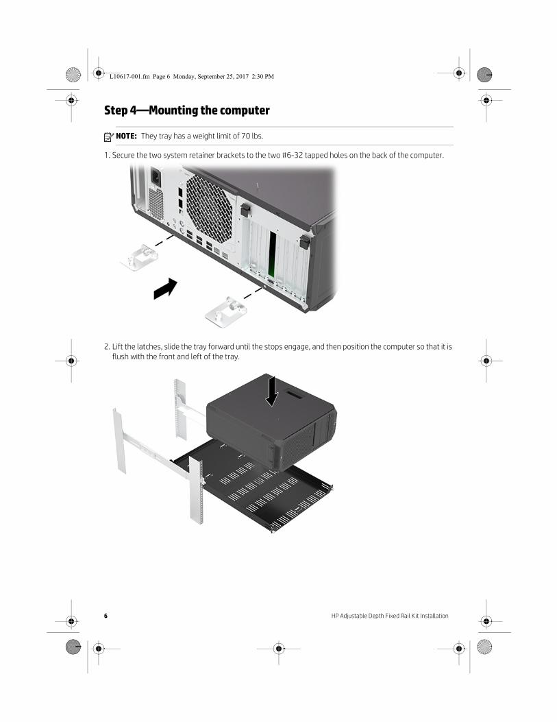
Step 4—Mounting the computer
NOTE: They tray has a weight limit of 70 lbs.
1. Secure the two system retainer brackets to the two #6-32 tapped holes on the back of the computer.
2. Lift the latches, slide the tray forward until the stops engage, and then position the computer so that it is flush with the front and left of the tray.
L10617-001.fm Page 6 Monday, September 25, 2017 2:30 PM

HP Adjustable Depth Fixed Rail Kit Installation 7
3. Secure the system retainer brackets to the tray by tightening the captive screws.
4. Secure the left side of the tray to the bottom of the computer using a #6-32 x 1/2” screw.
5. Rotate the latches upward and slide the tray completely to the rear of the rails.
L10617-001.fm Page 7 Monday, September 25, 2017 2:30 PM

6. Tighten the captive screws on the front of each rail.
Step 5—Reassembling the computer1. Reconnect external devices and power cord, and restore power to all external devices.
© Copyright 2017 HP Development Company, L.P.
The information contained herein is subject to change without notice. The only warranties for HP products and services are set forth in the express warranty statements accompanying such products and services. Nothing herein should be construed as constituting an additional warranty. HP shall not be liable for technical or editorial errors or omissions contained herein.
First Edition: September 2017
PRINTER: Replace this box with Printed- In (PI) Statement(s) as per spec.
NOTE: This box is simply a placeholder. PI Statement(s) do not have to fit inside the box but should be placed in this area.
L10617-001
*L10617-001*
L10617-001.fm Page 8 Monday, September 25, 2017 2:30 PM