hpi catalogue 2017 - edition - lemmerhydraulics.com · contents hpi catalogue edition 6 piston...
TRANSCRIPT

1
Edition 6
CATALOGUE
2
CONTENTS HPI CATALOGUE EDITION 6
PISTON PUMPS 4 AND 3 BOLT
BENT AXIS PISTON PUMPS
40/30 SERIES GEAR PUMPS
TAND M GEAR PUMPSE
VANE PUMPS
ADAPTORS, COUPLINGS, FLANGES
TIPPING VALVES
CONTROL VALVES
SWITCH SE
PTO S’
FILTER AND ACCESSORIESS
TANKS
FERRO BALL VALVES AND SWIVELS
FERRO COUPLERS
USEFUL FORMULAS PRESSURE CONVERSION THREAD SIZES,
PAGE
3
4
5
6
7
8
9/10
11
12
13
14
15
16
17/18
19

3
3 BOLT PISTON PUMPS (6 SPLINE)
80
80
13
15
4
80
f7-0
,06
-0,0
3
A
55
8,50
B
36,80 15
B8x32x35
14
DIN
ISO
1226,102
INLET
OU
TL
ET
8,10
C
D
PISTON PUMPS
PumpType
Max.Continuous
Speed (min -1)
MinIntermittent
Speed (min -1)
Max.Continuous
Pressure (BAR)
PartNumber
20CC
34CC
50CC
60CC
1200
1200
1200
1200
400
400
400
400
PPP20CC35M3
PPP34CC35M3
PPP46CC35M3
PPP60CC35M3
350
350
350
350
4 8BOLT PISTON PUMPS ( SPLINE)
PumpType
Max.Continuous
Speed (min -1)
MinIntermittent
Speed (min -1)
Max.Continuous
Pressure (BAR)
PartNumber
16CC
20CC
32CC
50CC
50CC
60CC
80CC
106CC
1200
1200
1200
1200
1200
1200
1200
1200
400
400
400
400
400
400
400
400
PPP16CC25M
PPP20CC35M
PPP32CC35M
PPP50CC25M
PPP50CC35M
PPP60CC35M
PPP80CC28M
PPP106CC28M
350
350
350
250
350
350
280
280

4
BENT AXIS PISTON PUMPS
To check in which direction the pump should rotate on your installation:
- heck the direction of rotation of the ;C PTO
- f the turns clockwise, the pump must rotate counter-clockwise,I PTO
and vice versa.
To change the direction of rotation of your 2 pump:PBA
emove the inlet fitting (2) and the 2 parts of the split ange (3).- R fl
emove the rotation setting screw (1).- R
6
1
INLET
OUTLET
AS DEL VERED.I
INLET
OUTLET
6
1DI IRECT ON OF
CHANGED.ROTAT ONI
HOW TO CHANGE THE D RECT ON OF ROTAT ON OF THE PUMPI I I emove the plug (6).- R
- ut the rotation setting screw (1) where the plug (6) was, and the plug (6)P
where the rotation setting screw (1) was.
- ut seal (5) on the inlet fitting, then the inlet fitting on the side where theP
plug (6) is, and fix with the split ange. Tighten with the screws (4).fl
Important note:
Do not rotate pump shaft at all until the rotation setting screw (1) is in place.
The rotation setting screw is always on the output (pressure) side.
1
2
3
4
5
6
BENT AXIS PISTON PUMPS
PartNo
PumpType
Displacement100 Rpm
Max PeakPressure
(Bar)
WeightKg
2PBA‐12
2PBA18
2PBA25
2PBA40
2PBA55
2PBA63
2PBA80
2PBA105
2PBA130
12CC
18CC
25CC
40CC
56CC
63CC
80CC
108CC
130CC
12.00
18.00
25.00
40.20
56.40
63.00
80.00
108.40
129.80
2300
2300
2300
1900
1900
1900
1700
1700
1700
350
350
350
350
350
350
350
350
350
400
400
400
400
400
400
400
400
400
9.40
9.40
9.90
10.90
11.90
11.90
15.40
15.90
16.30
3100
2900
2700
2500
2300
2300
2100
1900
1500
Max.Continuous
Speed (min -1)
MinIntermittent
Speed (min -1)
Max.Continuous
Pressure (BAR)

5
20/30/40 SERIES GEAR PUMPS
3 BOLT
3 Bolt
4 BOLT
4 Bolt
52
f7- 0
,06
- 0,0
3
3
15,50 16
21
222
UN
I6
x2
1x2
5
DIN
ISO
14 8x32x35
36,80
55
1226,10
2
8,50
M8
8,10
3 BOLT
20/30/40 SERIES GEAR PUMPS
20/30/40 SERIES GEAR PUMPS
PartNumber
PartNumber
PumpType
PumpType
Displacementcm3/Rpm
Displacementcm3/Rpm
WeightKg
WeightKg
DPAD30‐17
DPAD30‐27
DPAD30‐34
DPAD30‐43
DPAD30‐51
DPAD30‐61
DPAD30‐82
DPAD40-87
DPAD40‐109
DPAD40‐133
DPAD40‐151
DP20‐06BD
DP20‐10BD
DP30‐17
DP30‐27
DP30‐34
DP30‐43
DP30‐51
DP30‐61
DP30‐82
30‐17
30‐27
30‐34
30‐43
30‐51
30‐61
30‐82
40-87
40‐109
40‐133
40‐151
20‐06
20‐10
30‐17
30‐27
30‐34
30‐43
30‐51
30‐61
30‐82
17.20
27.30
33.80
43.80
51.70
61.90
82.10
87.20
109.00
132.90
151.00
6.10
10.20
17.20
26.50
34.30
43.70
51.40
60.80
81.00
2800
2800
2600
2300
2300
1900
1700
2600
2600
2400
2400
3000
3000
2500
2500
2200
2200
2000
1800
1500
260
260
260
260
240
220
180
240
235
225
180
280
280
260
260
260
260
240
220
180
11.00
11.50
12.00
12.50
13.00
13.50
14.00
18.00
22.50
23.50
24.00
4.0
4.5
10.50
10.90
11.40
12.00
12.50
13.00
13.80
Max.Continuous
Speed (min -1)
Max.Continuous
Speed (min -1)
Max.Continuous
Pressure (BAR)
Max.Continuous
Pressure (BAR)

6
55
80
f7-0
,06
-0,0
3
8,50 15
1226,102
A
B
C
6x21x25
21
222
UN
I
13
36,80
8,10
INLET
TANDEM GEAR PUMPS
PRIMARY PUMPS
FINAL PUMPS
PumpType
PumpType
Displacementcm3/Rpm
Displacementcm3/Rpm
WeightKg
WeightKg
DPAD40‐63
DPAD40‐73
DPAD40‐87
DPAD40‐109
DP30‐17
DP30‐27
DP30‐34
DP30‐43
DP30‐51
DP30‐61
DP40‐63
63
73
87
109
17
27
34
43
51
61
63
1500
1500
1300
1200
1500
1500
1500
1500
1500
1500
1500
240
240
210
190
260
260
260
240
220
200
220
16.30
16.80
17.50
18.00
10.50
10.90
11.40
12.00
12.50
16.30
17.50
Max.Continuous
Speed (min -1)
Max.Continuous
Speed (min -1)
Max.Continuous
Pressure (BAR)
Max.Continuous
Pressure (BAR)
AVAILABLE IN 3 BOLT ON REQUEST

7
VANE PUMPS
DOUBLE & SINGLE VANE PUMPS
PartNumber
Description CCPer Rev
VP 70-70 R/L
VP 78-34 R/L
VP 26 R/L
VP 34 R/L
VP 55 R/L
VP 63 R/L
VP 80 R/L
Double Vane
Double Vane
Single Vane
Single Vane
Single Vane
Single Vane
Single Vane
70+70
78+34
26
34
55
63
80
400-2500
400-2500
400-2500
400-2500
400-2500
400-2500
400-2500
240
210
210
210
210
210
210
Min/Max.Speed (RPM)
Max.Pressure (BAR)
The design of the ODF vane pumps makes them particularly
suitable for applications on trucks, especially vehicles operating
with hydraulic motors, like feed bulkers, fuel tankers etc. All the
components subject to wear, are contained in a cartridge unit
that can easily be removed for inspection and/or replacement
without disconnecting the pump from the circuit. This drastically
reduces expensive downtime. The vanes ensure a more lamina
flow instead of the more turbulent (pulsating) flow from a piston
pump, which is perfect for hydraulic motors, resulting in
extending the life and increasing efficiency.
The special design of the double-lip vanes renders the ODF vane
pumps ideally suitable for applications that require high pressure
levels and very low noise emissions. Furthermore, the two
opposed pumping chambers formed by the elliptical profile of the
cam, cancel out radial loads which dramatically reduces
ODF VANE PUMPS
OTHER SIZES (CC) AVAILABLE ON REQUEST.
AVAILABLE IN EITHER CLOCKWISE OR ANTI CLOCKWISE
STANDARD ISO 4 BOLT MOUNT 8 SPLINE SHAFT
vibrations and increases the pump’s lifespan considerably. In
addition to reliability, the ODF pump guarantees continuous high
volumetric efficiency during its whole service time. This
diminishes the requirement to compensate for the typical
efficiency loss of other kinds of pumps, that increases the truck
engine RPM, which in turn causes increased fuel consumption,
air pollution, fuel cost and engine wear etc. Such characteristics,
along with an extremely low noise-level, make ODF pumps
environmentally friendly in line with the latest ecological trend.
The pumps are extremely compact and are supplied with
different types of either ISO or UNI norm mountings, for direct
coupling with PTO and SAE norm hydraulic fittings. This, together
with the ability to orientate the inlet and outlet ports, make ODF
pumps very easy to install and guarantees their
interchangeability with other types of pumps.
8
139
18,5 18,5
84
50
55
Ø35
Ø80
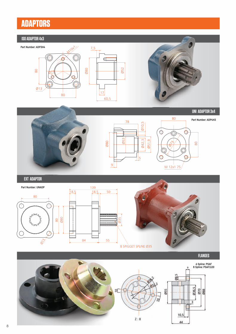
8 Ø35SPIGGET SPLINE
Ø13
80
80
ADAPTORS
ISO ADAPTOR 4x3
UNI ADAPTOR 3x4
EXT ADAPTOR
FLANGES
Part Number: ADP3H4
Part Number: ADP4H3
Part Number: UNADP
6 Spline: PSAF8 Spline: PSAF1120

9
89,50
119,5
0
G3/4"
G3/4
19633,50
G3/4"
G 1/4" G 1/4"
PUMP
CYLINDER
TANK
FASTSLOW
SINGLE ACTING TIPPING VALVE - SLOW DESCENT
SINGLE ACTING TIPPING VALVES - DOP19 HIGH PRESSURE
PartNumber
PartNumber
Flow Rate(L/Min)
Flow Rate(L/Min)
WeightKg
WeightKg
SATV‐12POLM
DOP19
DOP19H
110
140
140
170
170
250
190
190
260
6.00
5.00
5.00
ContinuousWorking
Pressure (BAR)
ContinuousWorking
Pressure (BAR)
Max.Continuous
Pressure (BAR)
Max.Continuous
Pressure (BAR)
TIPPING VALVES
10
238
378,50
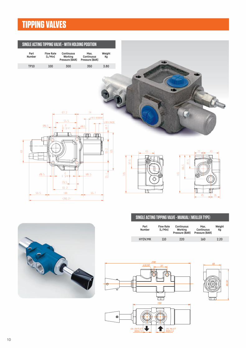
OIL OUTLETM22x1.5 M22x1.5
159
OIL INLET
85,5
0
48
TIPPING VALVES
SINGLE ACTING TIPPING VALVE - WITH HOLDING POSITION
SINGLE ACTING TIPPING VALVE - MANUAL ( MEILLER TYPE)
PartNumber
PartNumber
Flow Rate(L/Min)
Flow Rate(L/Min)
WeightKg
WeightKg
TP10
HYDV.MK
100
110
300
220
350
160
3.80
2.20
ContinuousWorking
Pressure (BAR)
ContinuousWorking
Pressure (BAR)
Max.Continuous
Pressure (BAR)
Max.Continuous
Pressure (BAR)
11
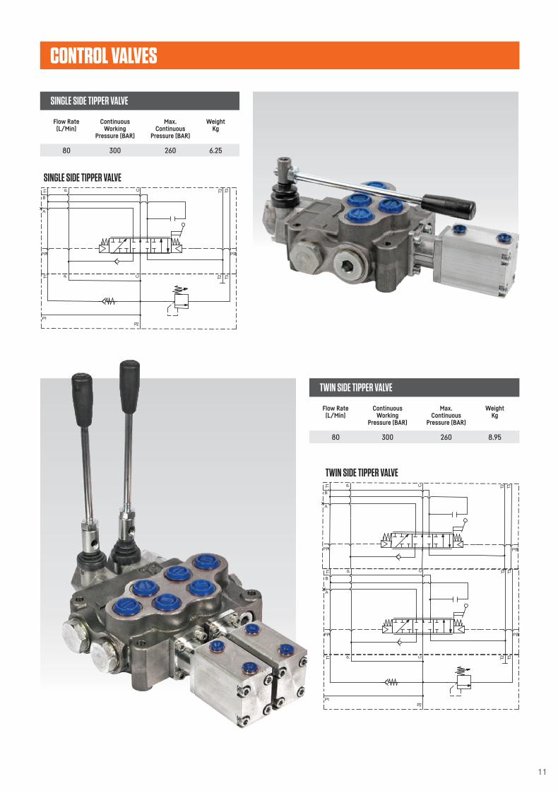
CONTROL SVALVE
SINGLE SIDE TIPPER VALVE
P2
P1
T1 P C T2
T3
A
B
T1 C T2P
PP1 PP2
T3
TWIN SIDE TIPPER VALVE
P2
P1
T1 P C T2
T3
A
B
T1 C T2P
PP1 PP2
T3
A
B
T1 C T2P
PP1 PP2
T3
SINGLE SIDE TIPPER VALVE
TWIN SIDE TIPPER VALVE
Flow Rate(L/Min)
Flow Rate(L/Min)
WeightKg
WeightKg
80
80
300
300
260
260
6.25
8.95
ContinuousWorking
Pressure (BAR)
ContinuousWorking
Pressure (BAR)
Max.Continuous
Pressure (BAR)
Max.Continuous
Pressure (BAR)

12
PNEUMATIC CAB CONTROL SWITCH
PartNumber
PneumaticInlet
PneumaticOutlet
WorkingEnvironment
CSPVA G 1/8” M5 12 5 PNEUMATIC
Max.Pressure
(BAR)
Min.Pressure
(BAR)
SWITCHES
PNEUMATIC AIR SWITCHES
INSIDE CAB CONTROL VALVE
PartNumber
PartNumber
Type
PneumaticInlet
Operations
CAC1
43001002(WITH LIGHT)
5/3WPV (spring return)
5/3WPVD (detent)
CAC1
CAC2
G 1/8”
G 1/8”
10
10
G 1/8”
G 1/8”
1/8” BSP
1/8” BSP
12
12
SINGLE
DOUBLE
Max.Pressure
(BAR)
PneumaticOutlet
PortSize
P.T.O FAIL SAFE SWITCH
PartNumber
PneumaticInlet
PTOFSW G 1/8” G 1/8” 12
PneumaticOutlet
Max. WorkingPressure
(BAR)
Max. WorkingPressure
(BAR)

13
POWER TAKE OFFS
EATON SIDEMOUNT PTOFULLER BOTTOM MOUNT
VARIOUS PTO’S AVAILABLE
EATON PTO
EATON PTO FS828209 DOUBLE GEAR ISO
EATON 6109-8209EATON OFFSET 4 bolt
FULLER PTOUNI 3 BOLT
FULLER PTOISO 4 BOLT
FULLER BOTTO MOUNT 4 BOLT PTO HEAVY DUTM Y
SCANIA PTO SCANIA PTO GRS900 3 BOLT (GRS900R)
ISUZU PTO ISUZU MLD6A ISUZU MBJ6T UNI PTOISUZU MYY5T UNI PTO
ISUZU MYY5T UNI - PTO MACHANICL CONTROL
MITSUBISHI PTOMITSUBISHI PTO M3S5 MERCEDES PTOMERCEDES ACTROS 270MM INTR
MERCEDESG85 OFFSET MERCEDES G85 SQUARE
MERCEDES G3
PTO (SINGLE GEAR) MERCEDES G100 PTOMERCEDES PTO G131/
210/240/240/260/221
MERCEDES G4 PTO MERCEDES PTO G125/210/240//255/260NISSAN
PTONISSAN MLS62B
PTO CABLE
PTO MECHANIC
CABLE CONTROL
VOLVO PTOVOLVO SR1700 COVER
CARDAN SHAFT
VOLVO SR62 COVERZF PTO
SQUARE PTO ZFZF OFF-SET PTO DBL GEAR (HEM)
ZF OFF-SET P.T.O CLOSED
ZF OFF-SET PTO
HEAVY DUTY
ZF S535 S636DOUBLE GEAR 1/1.30
ZF S535 S636 SINGLE GEAR ALUM PTO

14
FILTERS & ACCESSORIES
TANK MOUNTED FILTERS
PartNumber
Size
TTF-34
-100TTF
-114TTF
3/4” BSP
1” BSP
1 1/4” BSP
SOF-34
-114SOF
SPIN ON FILTERS
PartNumber
Size
3/4” BSP
1 1/4” BSP
LIT-1
-2LIT
-3LIT
OIL LEVEL INDICATORS
PartNumber
Size
76 mm
127 mm
254 mm
AB-12
-34AB
-2FB
AIR & FILLER BREATHERS
PartNumber
Size
1/2” BSP
3/4” BSP
52 mm

15
TANKS
SIDE MOUNTED TANKS
BEHIND CAB TANKS
TankVolume
TankVolume
WorkingVolume
WorkingVolume
80 LT
100 LT
120 LT
160 LT
190 LT
210 LT
256 LT
65 LT
95 LT
105 LT
120 LT
155 LT
175 LT
200 LT
220 LT
225 LT
264 LT
285 LT
65 LT
80 LT
100 LT
140 LT
160 LT
180 LT
230LT
55 LT
75 LT
90 LT
100 LT
135 LT
150 LT
180 LT
190 LT
190 LT
230 LT
250 LT
ALL TANKS ARE SUPPLIED WITH AIR BREATHER,
TANK MOUNTED RETURN FILTER AND OIL LEVEL INDICATOR
* DIMENSIONS ON REQUEST
* DIMENSIONS ON REQUEST

16
FERRO BALL VALVES AND SWIVELS
BALL VALVES
INLINE SWIVEL JOINTS
PartNumber
PartNumber
Description ThreadSize
ThreadSize
BV2‐04FB
BV2‐06FB
BV2‐08FB
BV2‐12FB
BV2‐16FB
BV2‐20FB
BV2‐24FB
BV2‐32FB
SJ‐04
SJ‐06
SJ‐08
SJ‐12
SJ‐16
SJ‐20
SJ90‐04
SJ90‐06
SJ90‐08
SJ90‐12
SJ90‐16
SJ90‐20
1/4” BSP Female HP Ball Valve
3/8” BSP Female HP Ball Valve
1/2” BSP Female HP Ball Valve
3/4” BSP Female HP Ball Valve
1” BSP Female HP Ball Valve
1 BSP Female HP Ball Valve�⁄�”
1 ” BSP Female HP Ball Valve�⁄�
2” BSP Female HP Ball Valve
1/4” BSP
3/8” BSP
1/2” BSP
3/4” BSP
1” BSP
1 ” BSP�⁄�
1/4” BSP
3/8” BSP
1/2” BSP
3/4” BSP
1” BSP
1 �⁄�” BSP
1/4”
3/8”
1/2”
3/4”
1”
1 ”�⁄�
1 ”�⁄�
2”
500
500
500
500
500
500
500
500
450
430
400
380
340
300
450
430
400
380
340
300
WorkingPressure (BAR)
WorkingPressure (BAR)
17
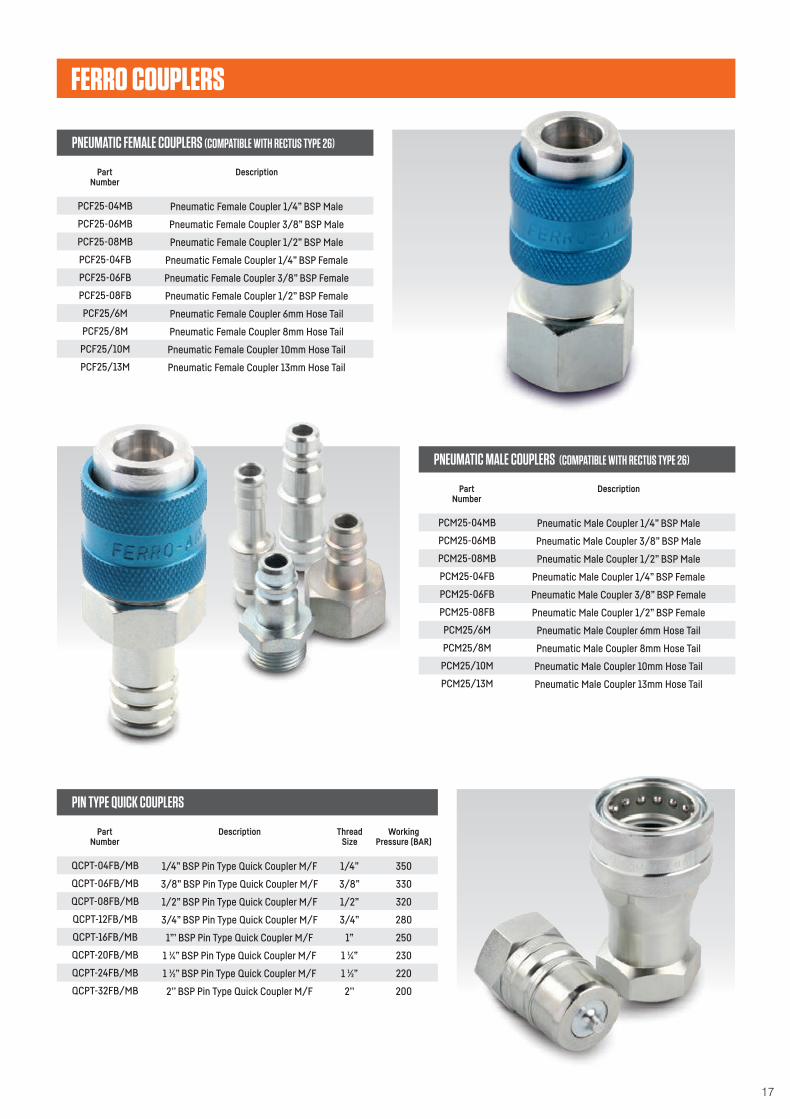
FERRO COUPLERS
PNEUMATIC FEMALE COUPLERS (COMPATIBLE WITH RECTUS TYPE 26)
PNEUMATIC MALE COUPLERS (COMPATIBLE WITH RECTUS TYPE 26)
PartNumber
PartNumber
Description
Description
PCF25‐04MB
PCF25‐06MB
PCF25‐08MB
PCF25‐04FB
PCF25‐06FB
PCF25‐08FB
PCF25/6M
PCF25/8M
PCF25/10M
PCF25/13M
PCM25‐04MB
PCM25‐06MB
PCM25‐08MB
PCM25‐04FB
PCM25‐06FB
PCM25‐08FB
PCM25/6M
PCM25/8M
PCM25/10M
PCM25/13M
Pneumatic Female Coupler 1/4” BSP Male
Pneumatic Female Coupler 3/8” BSP Male
Pneumatic Female Coupler 1/2” BSP Male
Pneumatic Female Coupler 1/4” BSP Female
Pneumatic Female Coupler 3/8” BSP Female
Pneumatic Female Coupler 1/2” BSP Female
Pneumatic Female Coupler 6mm Hose Tail
Pneumatic Female Coupler 8mm Hose Tail
Pneumatic Female Coupler 10mm Hose Tail
Pneumatic Female Coupler 13mm Hose Tail
Pneumatic Male Coupler 1/4” BSP Male
Pneumatic Male Coupler 3/8” BSP Male
Pneumatic Male Coupler 1/2” BSP Male
Pneumatic Male Coupler 1/4” BSP Female
Pneumatic Male Coupler 3/8” BSP Female
Pneumatic Male Coupler 1/2” BSP Female
Pneumatic Male Coupler 6mm Hose Tail
Pneumatic Male Coupler 8mm Hose Tail
Pneumatic Male Coupler 10mm Hose Tail
Pneumatic Male Coupler 13mm Hose Tail
PIN TYPE QUICK COUPLERS
PartNumber
Description ThreadSize
QCPT‐04FB/MB
QCPT‐06FB/MB
QCPT‐08FB/MB
QCPT‐12FB/MB
QCPT‐16FB/MB
QCPT‐20FB/MB
QCPT‐24FB/MB
QCPT‐32FB/MB
1/4” BSP Pin Type Quick Coupler M/F
3/8” BSP Pin Type Quick Coupler M/F
1/2” BSP Pin Type Quick Coupler M/F
3/4” BSP Pin Type Quick Coupler M/F
1”’ BSP Pin Type Quick Coupler M/F
1 ” BSP Pin Type Quick Coupler M/F�⁄�
1 ” BSP Pin Type Quick Coupler M/F�⁄�
2’’ BSP Pin Type Quick Coupler M/F
1/4”
3/8”
1/2”
3/4”
1”
1 ”�⁄�
1 ”�⁄�
2’’
350
330
320
280
250
230
220
200
WorkingPressure (BAR)
18
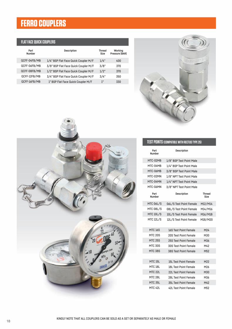
FLAT FACE QUICK COUPLERS
PartNumber
Description ThreadSize
QCFF‐04FB/MB
QCFF‐06FB/MB
QCFF‐08FB/MB
QCFF‐12FB/MB
QCFF‐16FB/MB
1/4” BSP Flat Face Quick Coupler M/F
3/8” BSP Flat Face Quick Coupler M/F
1/2” BSP Flat Face Quick Coupler M/F
3/4” BSP Flat Face Quick Coupler M/F
1” BSP Flat Face Quick Coupler M/F
1/4”
3/8”
1/2”
3/4”
1”
400
370
370
350
330
WorkingPressure (BAR)
PartNumber
ThreadSize
Description
MTC 06L/S
MTC 08L/S
MTC 10L/S
MTC 12L/S
MTC 16S
MTC 20S
MTC 25S
MTC 30S
MTC 38S
MTC 15L
MTC 18L
MTC 22L
MTC 28L
MTC 35L
MTC 42L
06L/S Test Point Female
08L/S Test Point Female
10L/S Test Point Female
12L/S Test Point Female
16S Test Point Female
20S Test Point Female
25S Test Point Female
30S Test Point Female
38S Test Point Female
15L Test Point Female
18L Test Point Female
22L Test Point Female
28L Test Point Female
35L Test Point Female
42L Test Point Female
M12/M14
M14/M16
M16/M18
M18/M20
M24
M30
M36
M42
M52
M22
M26
M30
M36
M42
M52
TEST POINTS (COMPATIBLE WITH RECTUS TYPE 26)
PartNumber
Description
MTC‐02MB
MTC‐04MB
MTC‐06MB
MTC-02MN
MTC-04MN
MTC-06MN
1/8” BSP Test Point Male
1/4” BSP Test Point Male
3/8” BSP Test Point Male
1/8” NPT Test Point Male
1/4” NPT Test Point Male
3/8” NPT Test Point Male
FERRO COUPLERS
KINDLY NOTE THAT ALL COUPLERS CAN BE SOLD AS A SET OR SEPARATELY AS MALE OR FEMALE
A
Dd B
19
4
6
8
10
12
16
20
24
9/16"-18
11/16"-16
13/16"-16
1"-14
1 3/16"-12
1 7/16"-12
1 11/16-12
2"-12
14.3
17.5
20.8
25.4
30.2
36.5
42.9
50.8
12.8
15.7
18.9
23.4
27.9
34.2
40.6
48.5
Dash Size-TPI oD iD
ORFS threads
4
5
6
8
10
12
14
16
20
24
32
7/16"-20
1/2"-20
9/16"-18
3/4"-16
7/8"-14
1 1/6"-12
1 3/16"-12
1 5/16"-12
1 5/8"-12
1 7/8"-12
2 1/2"-12
11.1
12.7
14.3
19.1
22.2
27
30.2
33.3
41.3
47.6
63.5
9.7
11.3
12.8
17.3
20.3
24.7
27.9
31
39
45.3
61.5
Dash Size-TPI oD iD
JIC SAE UNF/ / threads
2
4
6
8
12
16
20
24
32
1/8"-27
1/4"-18
3/8"-18
1/2"-14
3/4"-14
1"-11.5
11/4"-11.5
11/2"-11.5
2"-11.5
10.2
13.6
17.1
21.3
26.6
33.3
42
48.1
60.1
8.7
11.4
14.8
18.3
23.6
29.7
38.4
44.5
56.5
Dash Size-TPI oD iD
NPT threads
2
4
6
8
10
12
16
20
24
32
1/8"-28
1/4"-19
3/8"-19
1/2"-14
5/8"-14
3/4"-14
1"-11
11/4"-11
11/2"-11
2"-11
9.7
13.2
16.7
21
22.9
26.4
33.3
41.9
47.8
59.6
8.6
11.4
15
18.6
20.6
24.1
30.3
39
44.9
56.7
Dash Size-TPI oD iD
BSP threads
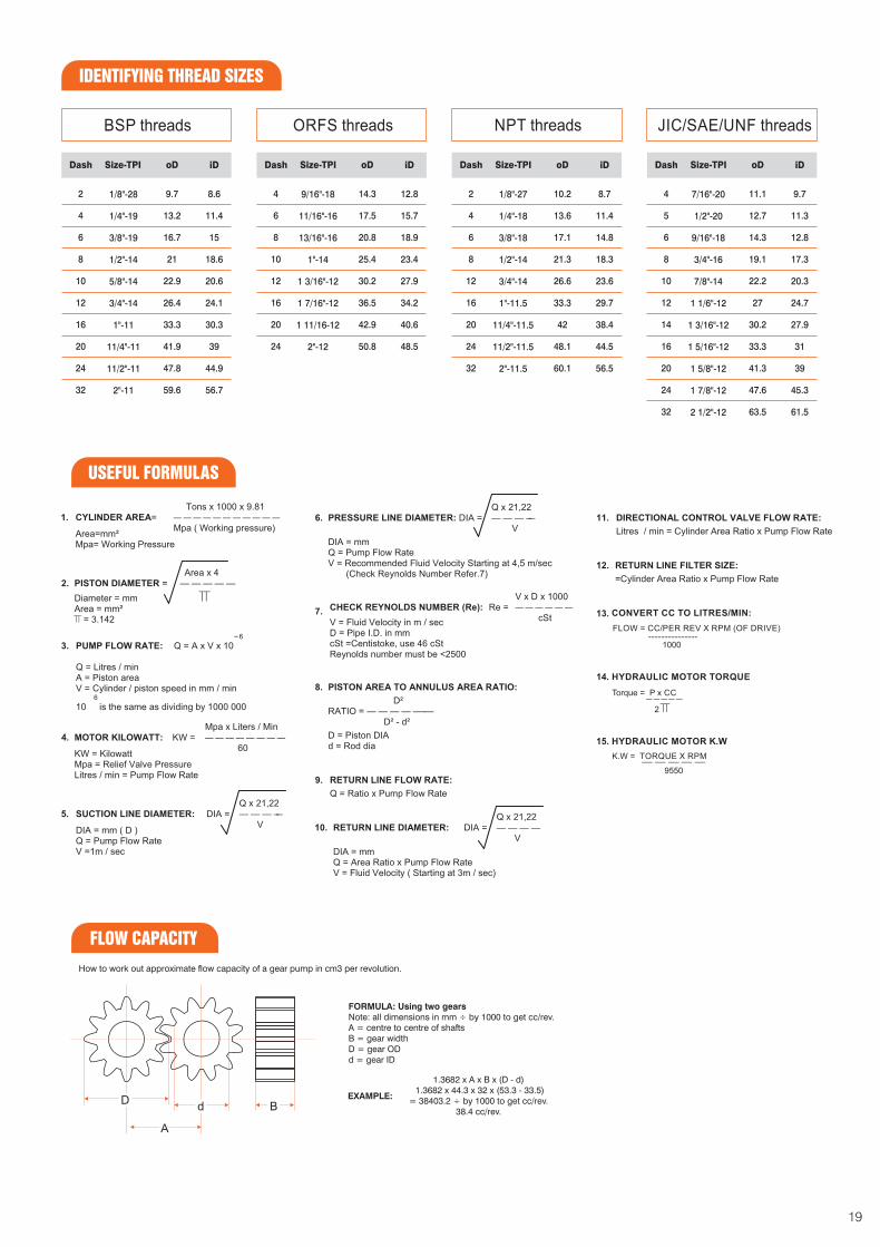
IDENTIFYING THREAD SIZES
USEFUL FORMULAS
FLOW CC PER REV RPM OF DRIVE= / X ( )---------------
1000
CONVERT CC TO LITRES MIN/ :
15. K.WHYDRAULIC MOTOR
K.W = XTORQUE RPM
9550
14. HYDRAULIC MOTOR TORQUE
Torque = P x CC
2
FLOW CAPACITY
How to work out approximate flow capacity of a gear pump in cm3 per revolution.
FORMULA: Using two gears
Note: all dimensions in mm ÷ by 1000 to get cc/rev.
A = centre to centre of shafts
B = gear width
D = gear OD
d = gear ID
1.3682 x A x B x (D - d)
1.3682 x 44.3 x 32 x (53.3 - 33.5)
= 38403.2 ÷ by 1000 to get cc/rev.
38.4 cc/rev.
EXAMPLE:
AA
DDdd BB

20
HYDRO-POWER.INDUSTRIES (Pty) Ltd.
Tel: 011 975 8806 Fax: 086 690 9973/8799
Sales General Enquires& : [email protected]
Rudi: [email protected]
083 292 5198
Accounts & : [email protected]
www.ptopumps.co.za
Although every effort has been made to ensure all information is correct at time of going to print.
We cannot accept responsibility for incorrect information supplied or errors which may occur during reproduction.