(hp)rf instrumentation moses chung apc, fermilab mucool rf workshop iii 2009. 7. 8. 1
TRANSCRIPT

(HP)RF Instrumentation
Moses Chung
APC, Fermilab
MuCool RF Workshop III
2009. 7. 8.
1

Break-down of “Breakdown”
2
1. Vacuum breakdown:• Field emission (protrusion) electrons+RF+B• Metal vapor Metal plasma Arc • Secondary emissions (by electrons, ions, photons)
2. Low pressure breakdown (~ glow):• Seed electrons (UV, cosmic ray, artificial source) • Electron multiplication by gas ionization• Secondary emission (by ion bombardment on cold cathode)
3. High pressure breakdown (~ spark):• Electron multiplication by gas ionization• Photo-ionization• Streamer propagation (faster, independent of cathode)
4. Beam-induced electron loading • Beam-impact and fast-electron-impact ionization of gas• Ohmic dissipation by electron-gas collisions• Significant reduction in quality factor, Q

Why High Pressure RF ?
3
Muon Beam
Muon Beam Muon BeamMuon Beam
eHH 22
dx
dE
RFfield B
?
High-pressure hydrogen gas (H2) inside the cavity:
1. To provide an energy absorber (dE/dx) 2. To enable higher accelerating RF field gradient in the presence
of the B fields (Paschen’s law, and electron’s m >> )3. To achieve ionization energy loss and RF energy regain
simultaneously (Key element for HCC)
Effects of beam-induced electrons are of great concern [A. Tollestrup].

HPRF Cavity
4
Metal sealing (use Aluminum gasket)Gas inlet (H2, N2, He, SF6)
Copper plated stainless steel
Semispherical electrode is replaceable (Cu, Al, Sn)
Power coupler(Fwd, Ref)
Optical port
0 200 400 600 800 1000 1200 1400 1600798
800
802
804
806
808
810
812
814
Superfish CalculationRe
son
an
ce f
req
ue
ncy
(M
Hz)
Pressure (PSI)
Experiments with H2
Cu electrode Al electrode Sn electrode
6.1~

Highlights of Previous Experiments
5
2004 Run 2008 Run
1. We identify gas and electrode breakdown regions.2. We confirm RF cavity works in the magnetic field.3. We demonstrate SF6 can impede electron accumulation.
CuHCC:~ 3000 psia ~ 20 MV/m
H2 (I = 15.5 eV)(I = 15.4 eV)
+Many mysteries
Conditioning
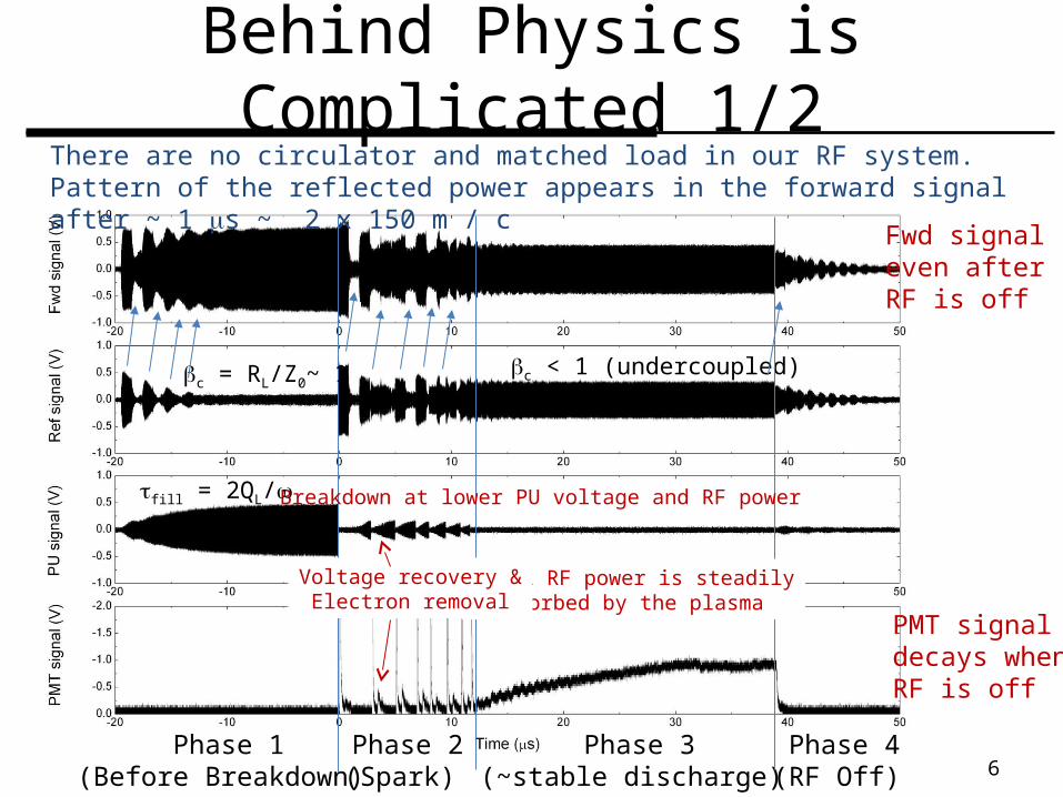
There are no circulator and matched load in our RF system. Pattern of the reflected power appears in the forward signal after ~ 1 s ~ 2 x 150 m / c
Phase 1(Before Breakdown)
Phase 2(Spark)
Phase 3(~stable discharge)
Phase 4(RF Off)
c = RL/Z0~ 1 c < 1 (undercoupled)
Behind Physics is Complicated 1/2
Fwd signaleven after RF is off
Small RF power is steadilyabsorbed by the plasma
PMT signaldecays when RF is off
Breakdown at lower PU voltage and RF power
Voltage recovery &Electron removal
fill = 2QL/
6

Behind Physics is Complicated 2/2
7
~ 8 cycle~ 8 cycle ~ 9 cycle
~ 8 cycle ~ 8 cycle ~ 8 cycle ~ 8 cycle
~ 8 cycle ~ 8 cycle ~ 8 cycleModulation (AM)
~ 10 % Increase in frequency
~ Undriven damped oscillation
Phase shift
ns 10
decay ~ 10 nsQ~ 25
No bigChange inFwd signal
reflectiontV- / V+
PMT rise time (~ 3 ns)What’s the color ? (H or Cu)
PMT saturation
Adjust according to PMT time delay calibration
There is uncertain time delay between PMT and Pickup signals.

What Happens with Beam ?
31000/cmeV 35proton 1
~)(
1
)(
)/(2 srW
sdxdEn
bi
e
Beam-impact ionization + Ionization by secondary electrons:p + H2 p + H2
+ + e- e- + H2 H2+ + 2e-
Fast electrons (< 40 keV, ~ 0.5 MeV rays)
Most electrons (>90%) are quickly thermalized inside the cavity by elastic and inelastic collisions, and drift with RF until annihilated by recombination, attachment, or diffusion.
H3+,H5
+,H7+,…
eegaegDAeregie n
DnnknnknnnkS
dt
dn2
2
-2 HHHe )(v
8

Effects of Electrons
Response of plasma electrons to the RF field is described by complex (Lorentz) conductivity:
Equivalent circuit model:
9
01
2,
)(21
)()(21
1 000
2000
20
Q
ffff
dVrE
dVrEr
Q mV
V DC
22
2
22
2
m
m
mm
mDC j
][102 11 psiafrequency collsionpm
me
eDC m
en
2
dt
dI
Q
R
dt
dV
QV
dt
d
QQdt
d bF
ec
L
22
11 002002
2
Additional damping term bybeam-induced electrons
Additional driving term by beam itself (LLRF)
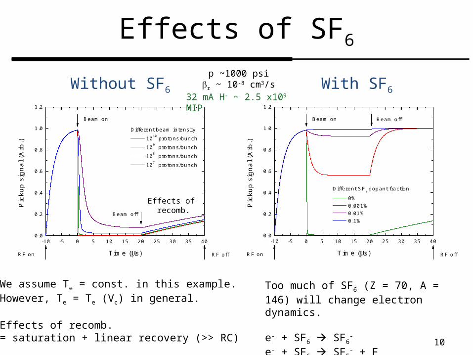
Effects of SF6
Without SF6
10
-10 -5 0 5 10 15 20 25 30 35 400.0
0.2
0.4
0.6
0.8
1.0
1.2
RF offRF on
Different beam intensity
1010 protons/bunch
109 protons/bunch
108 protons/bunch
107 protons/bunch
Pic
kup
sig
na
l (A
rb.)
Time (s)
Beam on
Beam off
With SF6
-10 -5 0 5 10 15 20 25 30 35 400.0
0.2
0.4
0.6
0.8
1.0
1.2
RF offRF on
Different SF6 dopant fraction
0% 0.001% 0.01% 0.1%
Pic
kup
sig
na
l (A
rb.)
Time (s)
Beam on Beam off
p ~1000 psir ~ 10-8 cm3/s
32 mA H- ~ 2.5 x10⁹ MIP
We assume Te = const. in this example.However, Te = Te (Vc) in general.
Effects of recomb. = saturation + linear recovery (>> RC)
Too much of SF6 (Z = 70, A = 146) will change electron dynamics.
e- + SF6 SF6-
e- + SF6 SF5- + F
Effects of recomb.

E/p~23 V/cm/torr
11
Criteria for breakdown:
E/p~15 V/cm/torr
,)()()( eaeDAei TkTkTk )(2
3)(357.0
71.0
tTp
tEe
Thermal energy gain from RF = Elastic & inelastic energy loss to gas
0 5 10 15 20 25 30 35 4010-18
10-16
10-14
10-12
10-10
10-8
10-6
ki
kDA
(v=0)
kDA
(v=0) + 0.01% ka
Att
ach
me
nt
rate
co
eff
icie
nt
(cm
3 s-1)
E/p (V/cm/Torr)E/p~12 V/cm/torr
E/p~22 V/cm/torrAl electrode run (10% error)
Simple Test of Theory

Actual Beam Test
12
305 mm
67.5 mmH- 95 ~ 10 mm-mrad, Ib ~ 32 mA, rb ~ 1 cm
1. Beam commissioning [C. Johnstone et. al.]:
MW4 MW5 MW6
MTA hallLinacHPRF2. Beam test [MCTF]:
- New LabVIEW-based DAQ [A. Kurup]- New coupling loop for magnetic field measurement- New optical (650 nm) diagnostics
Long C-magnet
400 MeV, 5 ns

Emittance Measurement
13
Tilt angle of the ellipse
Phase advanceof the particle
MW4 MW5 MW6
Multiwire (MW4) BPM8
Beam stop
1. Three grid method [C. Johnstone et. al.] Gaussian beam
2. Slit-grid method [Mehran Mohebbi (WVU) et. al.]:
Slit
Probe 4 (750 keV) Vertical
Long scanning timeSEM or Capture ?
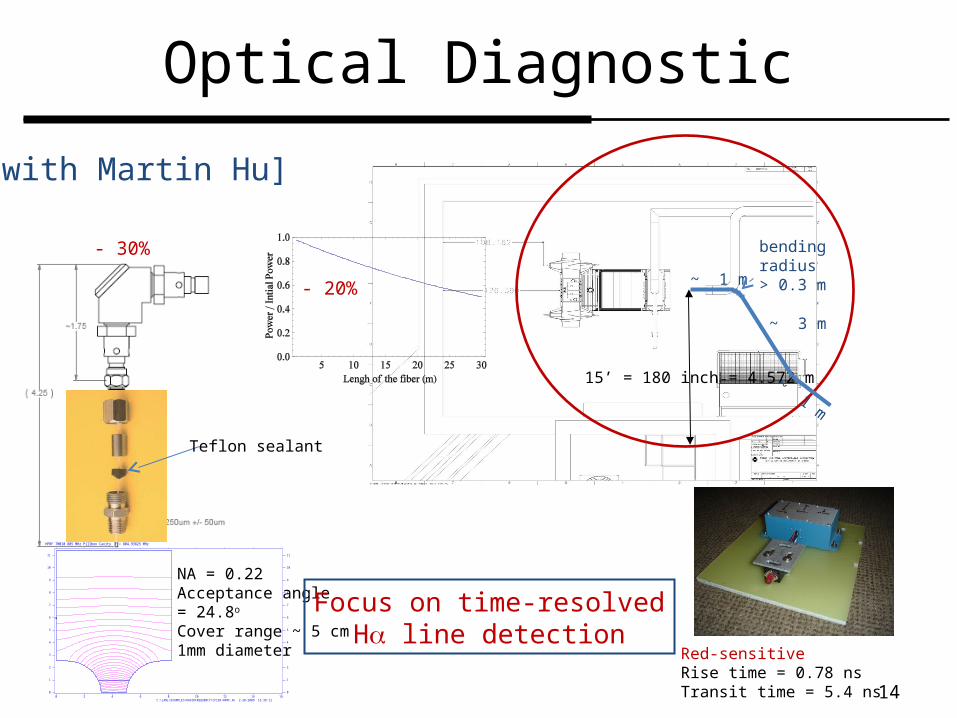
Optical Diagnostic
14
15’ = 180 inch = 4.572 m
~ 1 m
~ 3 m
~ 1 m
bending radius> 0.3 m
Red-sensitiveRise time = 0.78 nsTransit time = 5.4 ns
HPRF TM010 805 MHz Pillbox Cavity F = 804.93825 MHz
C:\LANL\EXAMPLES\RADIOFREQUENCY\CFISH\HPRF.AF 2-20-2009 16:38:12
0
1
2
3
4
5
6
7
8
9
10
11
0
1
2
3
4
5
6
7
8
9
10
11
0 2 4 6 8 10 12 14 16
NA = 0.22Acceptance angle = 24.8o Cover range ~ 5 cm1mm diameter
Teflon sealant
- 30%
- 20%
Focus on time-resolvedH line detection
[with Martin Hu]

Spectroscopy
15
H H H H
(c) Copper [CLIC]
e- + H2 H* + H + e- (Dissociative Excitation)
H2+ + e- H* + H
(Dissociative Recombination, H3+ ?)
e- + H2 H2* + e- (Excitation, Fulcher band)
- Can we have enough light ? (gas breakdown VS beam test)- What would be the required time scale ? (~ns VS ~ms) - What would be the reasonable resolution ? (filters VS grating)

Summary and Discussion
16
1. Beam test of the high pressure RF cavity is a high-priority R&D program in MTA.
2. We hope SF6 can remove electrons with minimal side effects.
3. What is the criteria to evaluate the feasibility of HPRF ?
4. What are the necessary equipments ?
5. Any synergy between vacuum RF and HPRF ?