hr hr710 - hankukrelay.co.kr · hr r-82 hankuk relay hr710 10a to 15a general purpose relay...
TRANSCRIPT

HR
HanKuk RelayR-82
HR710
10A to 15A General purpose relay
Features· 15A switching capability, 1 Form C
· Many variations and options available
· Are suppression barrier standard (3P, 4P)
· Conforms to various safety standard
Applications· Ideal for many varied applications
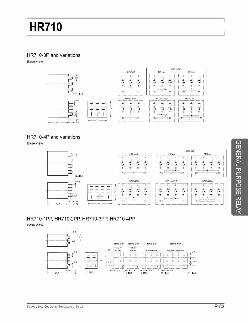
Dimensions (mm) and Schematic To convert into inches, multiply by 0.03937
ApprovalsUL
CUL
CE
HR710-1P and variationsBase view
HR710-2P and variationsBase view
Selection Guide & Technical Data R-83
HRHR710
HR710-3P and variationsBase view
HR710-4P and variationsBase view
HR710-1PP, HR710-2PP, HR710-3PP, HR710-4PPBase view
GENERALPURPOSE
RELAY

HR
HanKuk RelayR-84
HR710
HR710-1PB, HR710-2PB
HR710-3PB
HR710-4PB
Selection Guide & Technical Data R-85
HRHR710
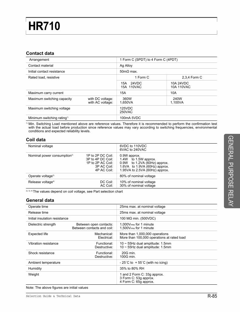
Contact dataArrangement 1 Form C (SPDT) to 4 Form C (4PDT)
Contact material Ag Alloy
Initial contact resistance 50mΩ max.
Rated load, resistive 1 Form C 2,3,4 Form C
15A 24VDC 10A 24VDC15A 110VAC 10A 110VAC
Maximum carry current 15A 10A
Maximum switching capacity with DC voltage: 360W 240Wwith AC voltage: 1,650VA 1,100VA
Maximum switching voltage 125VDC250VAC
Minimum switching rating1) 100mA 5VDC1) Min. Switching Load mentioned above are reference values. Therefore it is recommended to perform the confirmation test
with the actual load before production since reference values may vary according to switching frequencies, environmentalconditions and expected reliability levels.
Coil dataNominal voltage 6VDC to 110VDC
6VAC to 240VAC
Nominal power consumption2) 1P to 2P DC Coil: 0.9W approx.3P to 4P DC Coil: 1.4W to 1.5W approx.1P to 2P AC Coil: 0.9W to 1.2VA (60Hz) approx.
3P AC Coil: 1.6VA to 1.9VA (60Hz) approx.4P AC Coil: 1.95VA to 2.5VA (60Hz) approx.
Operate voltage3) 80% of nominal voltage
Release voltage4) DC Coil: 10% of nominal voltageAC Coil: 30% of nominal voltage
2), 3), 4) The values depend on coil voltage, see Part selection chart
General dataOperate time 25ms max. at nominal voltage
Release time 25ms max. at nominal voltage
Initial insulation resistance 100 MΩ min. (500VDC)
Dielectric strength Between open contacts: 1,000Vrms for 1 minuteBetween contacts and coil: 1,500Vrms for 1 minute
Expected life Mechanical: More than 1,000,000 operationsElectrical: More than 100,000 operations at rated load
Vibration resistance Functional: 10 ~ 55Hz dual amplitude: 1.5mmDestructive: 10 ~ 55Hz dual amplitude: 1.5mm
Shock resistance Functional: 20G min.Destructive: 100G min.
Ambient temperature - 25˚C to + 55˚C (with no icing)
Humidity 35% to 80% RH
Weight 1 and 2 Form C: 33g approx.3 Form C: 53g approx.4 Form C: 65g approx.
Note: The above figures are initial values
GENERALPURPOSE
RELAY

HR
HanKuk RelayR-86
HR710
Part selectionFill in the codes to the part number by selecting them from the part number description
Part numberNominal Coil Nominal Must operate Must release Max Nominalvoltage resistance current voltage voltage voltage power(VDC) (Ω ± 10%) (mA) (V) (V) (V) (W.VA)
Form C, 2 Form C, DC CoilHR710- 6VDC 6 40 150 4.8 0.6 6.6HR710- 12VDC 12 160 75 9.6 1.2 13.2 0.9HR710- 24VDC 24 650 36.9 19.2 2.4 26.4 approx
HR710- 48VDC 48 2,600 18.5 38.4 4.8 52.8HR710- 100/110VDC 100/110 11,000 9.1/10 80/88 10/11 110/121 1.1 approx1 Form C, 2 Form C, AC CoilHR710- 6VAC 6 12.2 214.1 183 4.8 1.8 6.6
1.0 to 1.2 HR710- 12VAC 12 46 106.5 91 9.6 3.6 13.2 approx HR710- 24VAC 24 180 53.8 46 19.2 7.2 26.4 (60Hz) HR710- 50VAC 50 788 25.7 22 40 15 55HR710- 100/110VAC 100/110 3,750 11.7/12.9 10/11 80/88 30/33 110/121
9.0 to 1.2HR710- 110/120VAC 110/120 4,430 9.9/10.8 8.4/9.2 88/96 33/36 121/132 approxHR710- 200/220VAC 200/220 12,950 6.2/6.8 5.3/5.8 160/176 60/66 220/242 (60Hz)HR710- 220/240VAC 220/240 18,790 4.8/5.3 4.2/4.6 176/192 66/72 242/264
Note: All values in the chart are measured at 23˚C
50Hz 60Hz
Part number description
HR710
Contact arrangement1P: 1 Form C2P: 2 Form C3P: 3 Form C4P: 4 Form C
Mounting & TerminalNone: Socket – plug-in, solderP: PC Board – pinB: Flange – tab, Quick-connect
OptionsNone: StandardL: LED indicator (DC coil: green, AC coil: red) T: Test buttonLT: LED indicator + Test buttonD: Freewheeling diodeLD: LED indicator + freewheeling diodeLC: LED indicator + Built-in the Surge Absorbent Circuit
Coil voltage6VDC 6VAC 100/110VAC
12VDC 12VAC 110/120VAC24VDC 24VAC 200/220VAC48VDC 50VAC 220/240VAC100/110VDC
Part number description is provided for reference, part number can not be arbitrarily composed. Refer to the partnumbers shown in the table below. Special designs to customer specifications are possible; please contact HR.
Selection Guide & Technical Data R-87
HRHR710
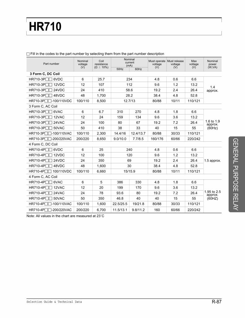
Fill in the codes to the part number by selecting them from the part number description
Part numberNominal Coil Nominal Must operate Must release Max Nominalvoltage resistance current voltage voltage voltage power
(V) (Ω ± 10%) (mA) (V) (V) (V) (W,VA)
3 Form C, DC CoilHR710-3P 6VDC 6 25.7 234 4.8 0.6 6.6HR710-3P 12VDC 12 107 112 9.6 1.2 13.2
1.4HR710-3P 24VDC 24 410 58.6 19.2 2.4 26.4 approx. HR710-3P 48VDC 48 1,700 28.2 38.4 4.8 52.8HR710-3P -100/110VDC 100/110 8,500 12.7/13 80/88 10/11 110/1213 Form C, AC CoilHR710-3P 6VAC 6 6.7 310 270 4.8 1.8 6.6HR710-3P 12VAC 12 24 159 134 9.6 3.6 13.2
1.6 to 1.9HR710-3P 24VAC 24 100 80 67 19.2 7.2 26.4 approx.HR710-3P 50VAC 50 410 38 33 40 15 55 (60Hz) HR710-3P -100/110VAC 100/110 2,300 14.4/16 12.4/13.7 80/88 30/33 110/121HR710-3P -200/220VAC 200/220 8,650 9.0/10.0 7.7/8.5 160/176 60/66 220/2424 Form C, DC CoilHR710-4P 6VDC 6 25 240 4.8 0.6 6.6HR710-4P 12VDC 12 100 120 9.6 1.2 13.2HR710-4P 24VDC 24 350 69 19.2 2.4 26.4 1.5 approx.HR710-4P 48VDC 48 1,600 30 38.4 4.8 52.8HR710-4P 100/110VDC 100/110 6,660 15/15.9 80/88 10/11 110/1214 Form C, AC CoilHR710-4P 6VAC 6 5 386 330 4.8 1.8 6.6HR710-4P 12VAC 12 20 199 170 9.6 3.6 13.2
1.95 to 2.5HR710-4P 24VAC 24 78 93.6 80 19.2 7.2 26.4 approx.HR710-4P 50VAC 50 350 46.8 40 40 15 55 (60HZ) HR710-4P -100/110VAC 100/110 1,600 22.5/25.5 19/21.8 80/88 30/33 110/121
HR710-4P -200/220VAC 200/220 6,700 11.5/13.1 9.8/11.2 160 60/66 220/242
Note: All values in the chart are measured at 23˚C
50Hz 60Hz
GENERALPURPOSE
RELAY
HR
HanKuk RelayR-88
HR710
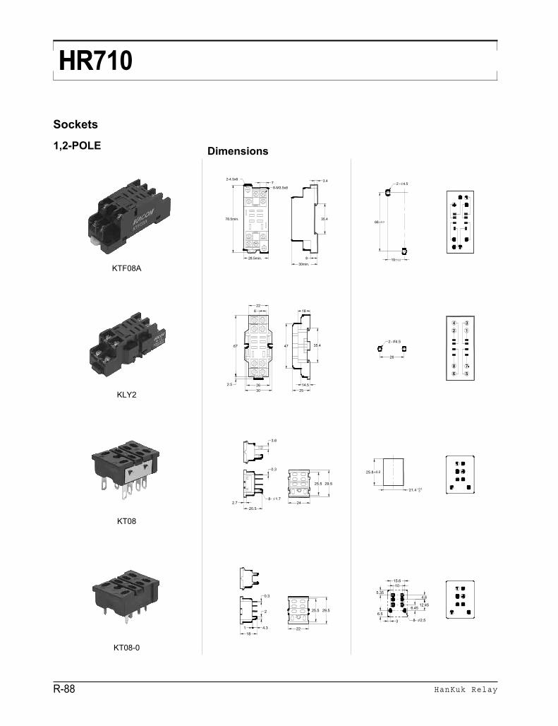
Sockets
1,2-POLE Dimensions
KTF08A
KLY2
KT08
KT08-0
Selection Guide & Technical Data R-89
HRHR710
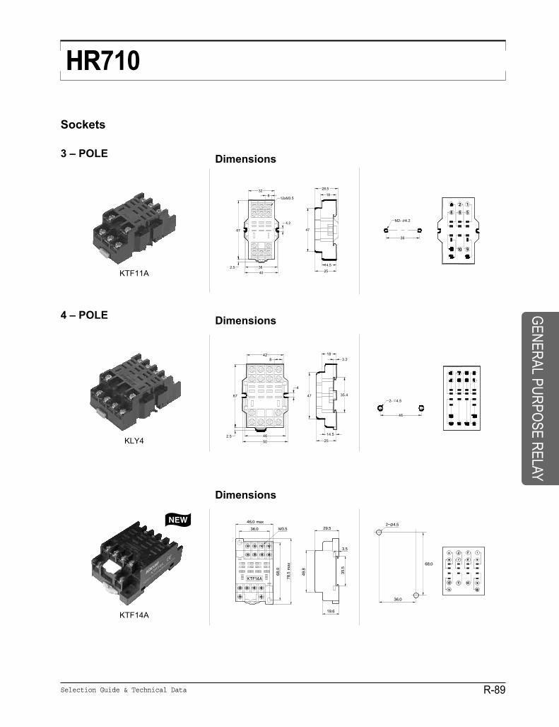
Sockets
3 – POLE Dimensions
KTF11A
4 – POLE Dimensions
KLY4
Dimensions
KTF14A
GENERALPURPOSE
RELAY