hscadcreator help - hachisoft apps
TRANSCRIPT

© 2007 Hachisoft Corporation
hsCADCreator Help

All rights reserved. No parts of this work may be reproduced in any form or by any means - graphic, electronic, ormechanical, including photocopying, recording, taping, or information storage and retrieval systems - without thewritten permission of the publisher.
Products that are referred to in this document may be either trademarks and/or registered trademarks of therespective owners. The publisher and the author make no claim to these trademarks.
While every precaution has been taken in the preparation of this document, the publisher and the author assume noresponsibility for errors or omissions, or for damages resulting from the use of information contained in this documentor from the use of programs and source code that may accompany it. In no event shall the publisher and the author beliable for any loss of profit or any other commercial damage caused or alleged to have been caused directly orindirectly by this document.
Printed: February 2008 in Colville, WA 99114
hsCADCreator Help
© 2007 Hachisoft Corporation

3Contents
3
© 2007 Hachisoft Corporation
Table of Contents
Foreword 0
Part I Introduction 9
................................................................................................................................... 91 Quick Start
.......................................................................................................................................................... 10Open hsCADCreator
.......................................................................................................................................................... 10Evaluation (Trial Version)
.......................................................................................................................................................... 11Creating Drawings
.......................................................................................................................................................... 12Editing Drawings
.......................................................................................................................................................... 13Viewing Drawings
.......................................................................................................................................................... 14PrintingDrawings
................................................................................................................................... 152 Terminology
................................................................................................................................... 173 Feature List
Part II Handbook 20
................................................................................................................................... 201 Concepts
.......................................................................................................................................................... 21Entities
......................................................................................................................................................... 22Point
......................................................................................................................................................... 23Line
......................................................................................................................................................... 24Multi Line
......................................................................................................................................................... 26Planar Polyline
......................................................................................................................................................... 273D Polyline
......................................................................................................................................................... 28Arc
......................................................................................................................................................... 30Circle
......................................................................................................................................................... 32Ellipse
......................................................................................................................................................... 33Dimension
......................................................................................................................................... 35Aligned Dimension
......................................................................................................................................... 36Linear Dimension
......................................................................................................................................... 38Ordinate Dimension
......................................................................................................................................... 39Radial Dimension
......................................................................................................................................... 41Diametric Dimension
......................................................................................................................................... 42Angular Dimension
......................................................................................................................................................... 43Text
......................................................................................................................................................... 45Hatch
......................................................................................................................................................... 46Poly Face Mesh
......................................................................................................................................................... 46Block Reference
......................................................................................................................................................... 47Image Insertion
......................................................................................................................................................... 49Paperspace Viewport
.......................................................................................................................................................... 50Objects
......................................................................................................................................................... 51Colors
......................................................................................................................................................... 51Dimension Styles
......................................................................................................................................................... 59User Coordinate System
......................................................................................................................................................... 60External References
......................................................................................................................................................... 60Hatch Style
......................................................................................................................................... 60Hatch Gradients
......................................................................................................................................... 61Hatch Patterns
......................................................................................................................................................... 61Block Definition
......................................................................................................................................................... 63Image Definition
......................................................................................................................................................... 64Layers

hsCADCreator Help4
© 2007 Hachisoft Corporation
......................................................................................................................................................... 64Layouts
......................................................................................................................................................... 66Linetypes
......................................................................................................................................................... 67Multi Line Style
......................................................................................................................................................... 68Plot Settings
......................................................................................................................................................... 69Text Styles
......................................................................................................................................................... 70Modelspace Viewport
.......................................................................................................................................................... 71Snap Point Settings
......................................................................................................................................................... 72Entity Snap Points
......................................................................................................................................................... 74Grid Snap Points
.......................................................................................................................................................... 74Entity Grip Points
.......................................................................................................................................................... 75Grid
.......................................................................................................................................................... 76Drawing Settings
.......................................................................................................................................................... 77Data Types and Properties
.......................................................................................................................................................... 79Property Trees
.......................................................................................................................................................... 80Tools
.......................................................................................................................................................... 81Toolbars
.......................................................................................................................................................... 83Docking Window
......................................................................................................................................................... 86Docking Procedure
.......................................................................................................................................................... 88Dialogs
.......................................................................................................................................................... 89Undo/Redo
................................................................................................................................... 902 User Interface
.......................................................................................................................................................... 90hsCADCreator Menus
......................................................................................................................................................... 93File Menu
......................................................................................................................................................... 94Edit Menu
......................................................................................................................................................... 94View Menu
......................................................................................................................................................... 96Manage Menu
......................................................................................................................................................... 97Tool Menu
......................................................................................................................................................... 99Options Menu
......................................................................................................................................................... 99Window Menu
......................................................................................................................................................... 100Help Menu
.......................................................................................................................................................... 100hsCADCreator Tools
......................................................................................................................................................... 101Selection Tool
......................................................................................................................................................... 103Create Tools
......................................................................................................................................... 105Point Tool
......................................................................................................................................... 106Line Tool
......................................................................................................................................... 108Multi Line Tool
......................................................................................................................................... 110Planar Polyline Tool
......................................................................................................................................... 1123D Polyline Tool
......................................................................................................................................... 113Arc Tools
................................................................................................................................... 114Start-Middle-End Arc Tool
................................................................................................................................... 115Start-Center-End Arc Tool
................................................................................................................................... 117Start-Center-Angle Arc Tool
................................................................................................................................... 119Start-Center-Chord Length Arc Tool
......................................................................................................................................... 120Circle Tool
......................................................................................................................................... 121Ellipse Tool
......................................................................................................................................... 123Dimension Tool
................................................................................................................................... 124Aligned Dimension Tool
................................................................................................................................... 126Linear Dimension Tool
................................................................................................................................... 128Ordinate Dimension Tool
................................................................................................................................... 130Radial Dimension Tool
................................................................................................................................... 132Diametric Dimension Tool
................................................................................................................................... 134Angular Dimension Tool
......................................................................................................................................... 136Text Tool
......................................................................................................................................... 138Hatch Tool

5Contents
5
© 2007 Hachisoft Corporation
......................................................................................................................................... 139Poly Face Mesh Tool
......................................................................................................................................... 140Block Definition Tool
......................................................................................................................................... 142Block Insertion Tool
......................................................................................................................................... 144Image Insertion Tool
......................................................................................................................................... 146Viewport Tool
......................................................................................................................................................... 147Modify Tools
......................................................................................................................................... 148Translate Tool
......................................................................................................................................... 150Rotate Tool
......................................................................................................................................... 152Explode Tool
......................................................................................................................................... 153Delete Tool
......................................................................................................................................... 154Scale Entities Uniformly Tool
......................................................................................................................................... 155Scale Entities Non-uniformly Tool
......................................................................................................................................... 157Trim Tool
......................................................................................................................................... 158Extend Tool
......................................................................................................................................... 159Clone Tool
................................................................................................................................... 160Radial Clone Tool
................................................................................................................................... 163Linear Clone Tool
................................................................................................................................... 165Planar Clone Tool
................................................................................................................................... 1683-Axial CloneTool
......................................................................................................................................... 171Mirror Tool
......................................................................................................................................................... 173View Tools
......................................................................................................................................... 175Zoom Tools
................................................................................................................................... 175Zoom to Window Tool
................................................................................................................................... 176Zoom In Tool
................................................................................................................................... 177Zoom Out Tool
................................................................................................................................... 178Zoom Extent Tool
......................................................................................................................................... 178Pan View Tool
......................................................................................................................................... 179Rotate View Tools
................................................................................................................................... 180Rotate About Eye Vector Tool
................................................................................................................................... 181Rotate About Vertical Vector Tool
................................................................................................................................... 182Rotate About Horizontal Vector Tool
................................................................................................................................... 183Rotate View 3D Tool
......................................................................................................................................... 184Divide Viewport Tool
......................................................................................................................................... 186Pre-configured Viewport Tools
......................................................................................................................................................... 187Preset View Snap Tools
......................................................................................................................................... 188Top View Tool
......................................................................................................................................... 189Bottom View Tool
......................................................................................................................................... 189Front (South) View Tool
......................................................................................................................................... 190Back (North) View Tool
......................................................................................................................................... 190Left Side (West) View Tool
......................................................................................................................................... 191Right Side (East) View Tool
......................................................................................................................................... 191Southwest View Tool
......................................................................................................................................... 192Southeast View Tool
......................................................................................................................................... 192Northeast View Tool
......................................................................................................................................... 193Northwest View Tool
......................................................................................................................................................... 193Draw Plane Tools
......................................................................................................................................... 195Preset UCS View Snaps
................................................................................................................................... 195Snap UCS to Top View Tool
................................................................................................................................... 196Snap UCS to Bottom View Tool
................................................................................................................................... 197Snap UCS to Front (South) View Tool
................................................................................................................................... 197Snap UCS to Back (North) View Tool
................................................................................................................................... 197Snap UCS to Left (West) View Tool
................................................................................................................................... 198Snap UCS to Right (East) View Tool
......................................................................................................................................... 198Rotate UCS Tools

hsCADCreator Help6
© 2007 Hachisoft Corporation
................................................................................................................................... 199 Rotate UCS About X-axis Tool
................................................................................................................................... 201Rotate UCS About Y-axis Tool
................................................................................................................................... 202Rotate UCS About Z-axis Tool
................................................................................................................................... 203Rotate UCS About Line Tool
......................................................................................................................................... 205Translate UCS Tools
................................................................................................................................... 206Translate UCS Origin Along X-axis Tool
................................................................................................................................... 207Translate UCS Origin Along Y-axis Tool
................................................................................................................................... 208Translate UCS Origin Along Z-axis Tool
................................................................................................................................... 209Translate UCS Origin to Point Tool
......................................................................................................................................... 210Align UCS to Current View Tool
......................................................................................................................................... 211Align Current View to UCS Tool
......................................................................................................................................... 211Move UCS Origin to WCS Origin Tool
......................................................................................................................................... 212Align UCS Axis to WCS Axis Tool
......................................................................................................................................... 212Align UCS to Selected Entities
......................................................................................................................................................... 213Rendering Tools
......................................................................................................................................... 2132D Wireframe Tool
......................................................................................................................................... 2143D Wireframe Tool
......................................................................................................................................... 214Hidden Tool
......................................................................................................................................... 214Flat ShadedTool
......................................................................................................................................... 215Gouraud ShadedTool
......................................................................................................................................... 216Flat Shaded With EdgesTool
......................................................................................................................................... 216Gouraud Shaded With EdgesTool
......................................................................................................................................... 217Regenerate Tool
......................................................................................................................................................... 217Library Tools
......................................................................................................................................... 218Manage Blocks Tool
......................................................................................................................................... 220Manage Colors Tool
......................................................................................................................................... 221Manage Dimension Styles Tool
......................................................................................................................................... 223Manage External References Tool
......................................................................................................................................... 224Manage Hatch Styles Tool
................................................................................................................................... 225Manage Hatch Gradient
................................................................................................................................... 227Manage Hatch Pattern
......................................................................................................................................... 228Manage Image Definitions Tool
......................................................................................................................................... 230Manage Layers Tool
......................................................................................................................................... 232Manage Layouts Tool
......................................................................................................................................... 233Manage Linetypes Tool
......................................................................................................................................... 235Manage Multi Line Styles
......................................................................................................................................... 236Manage Named Views Tool
......................................................................................................................................... 238Manage Plot Settings Tool
......................................................................................................................................... 239Manage Text Styles Tool
......................................................................................................................................... 241Manage User Coordinate Systems Tool
......................................................................................................................................... 242Manage Viewports Tool
......................................................................................................................................... 243Quick Layer View Tool
......................................................................................................................................................... 244Measure Tools
......................................................................................................................................... 245Measure Distance Tool
......................................................................................................................................... 247Measure Area Tool
......................................................................................................................................... 249Measure Angle Tool
.......................................................................................................................................................... 250hsCADCreator Toolbars
......................................................................................................................................................... 251Entity Toolbar
......................................................................................................................................................... 253Modify Toolbar
......................................................................................................................................................... 253View Toolbar
......................................................................................................................................................... 254Draw Plane/UCS Toolbar
......................................................................................................................................................... 256Rendering Toolbar
......................................................................................................................................................... 256File Toolbar
......................................................................................................................................................... 257Library Toolbar

7Contents
7
© 2007 Hachisoft Corporation
......................................................................................................................................................... 257Measure Toolbar
......................................................................................................................................................... 258Snaps Toolbar
.......................................................................................................................................................... 258hsCADCreator Property Trees
......................................................................................................................................................... 259Selection Property Tree
......................................................................................................................................................... 260Tool Property Tree
......................................................................................................................................................... 261Snap Property Tree
......................................................................................................................................................... 262Drawing Property Tree
......................................................................................................................................................... 263Viewport Property Tree
.......................................................................................................................................................... 264hsCADCreator Dialogs
......................................................................................................................................................... 264About hsCADCreator Dialog
......................................................................................................................................................... 264Application Settings Dialog
......................................................................................................................................................... 266Print Dialog
.......................................................................................................................................................... 267Notify Window
.......................................................................................................................................................... 269Status Bar
.......................................................................................................................................................... 270Visual Aids
.......................................................................................................................................................... 271Keyboard Shortcuts
.......................................................................................................................................................... 275Customizing Toolbars
.......................................................................................................................................................... 279Workspace Layout
.......................................................................................................................................................... 281Layer Window
.......................................................................................................................................................... 282Library Window
.......................................................................................................................................................... 285Help Window
................................................................................................................................... 2863 Export
.......................................................................................................................................................... 287DWG Format
.......................................................................................................................................................... 287DXF Format
.......................................................................................................................................................... 288DWF : Multi Layout Format
.......................................................................................................................................................... 289DWF : Single Layout Format
.......................................................................................................................................................... 290DXB Format
.......................................................................................................................................................... 291Email Attachment
.......................................................................................................................................................... 292Image Format
.......................................................................................................................................................... 293PDF Format
.......................................................................................................................................................... 294SVG Format
................................................................................................................................... 2954 Supported Files and Formats
Part III Licensing 296
................................................................................................................................... 2961 Licensing Application
................................................................................................................................... 2982 Managing License Groups
.......................................................................................................................................................... 298Activating a Seat
.......................................................................................................................................................... 300Remove a Seat
................................................................................................................................... 3023 Trial Extension
................................................................................................................................... 3034 License Agreements
.......................................................................................................................................................... 303hsCADCreator End-User License Agreement
.......................................................................................................................................................... 305Apache License Agreement
.......................................................................................................................................................... 307OpenCascade License Agreement
Part IV Frequently Asked Questions 310
Part V Support and Feedback 313
Part VI Version History 313

hsCADCreator Help8
© 2007 Hachisoft Corporation
Index 314

Introduction 9
© 2007 Hachisoft Corporation
1 Introduction
This help document includes information on how to Quickly get Started in hsCADCreator as wellas the more in-depth details of the hsCADCreator Handbook . Also available are Licensing ,Support , and Version Information, as well as Frequently Asked Questions .
1.1 Quick Start
Quick Start provides an overview of hsCADCreator. It is a primary goal of Hachisoft Corporation
that hsCADCreator be a powerful tool in the hands of its user clientele. There are four fundamental
ways to use hsCADCreator. Click on a links below to learn more about hsCADCreator.
1. Creating Drawings
2. Editing Drawings
3. Printing Drawings
4. Viewing Drawings
To insure your ability to utilize this software we recommend the following steps:
Become acquainted with the ToolsBecome acquainted with all of the tools --one may be more effective for your jobundertaking than another; knowing which tool to access and how to use it is critical to
efficiently using hsCADCreator.
Become acquainted with User Interface
9
20 296
313 313 310
11
12
14
13
100

hsCADCreator Help10
© 2007 Hachisoft Corporation
Our user interface is very dynamic and customizable . As you become familiar withhsCADCreator you will be able to modify the user interface and layout to fit your personalneeds. Each window (Help, Notification , Layers, Library,Drawing, and Viewport) withinhsCADCreator has a purpose. Each will help you along on your way to utilizing thissoftware to its full potential.
Use the Help Manual Use the program Help manual (or the hard copy Owners Manual). Questions you may have
can often be answered by reading the pertinent information there.
Check Frequently Asked Questions Check the Frequently Asked Questions (FAQ) page. Your inquiry may already be coveredthere. Contact Us
Contact us if steps (1), (2), or (3) have not alleviated your questions about how to use theprogram. We would be glad to assist you.
Note:
Evaluators of the free trial version of hsCADCreator may want to peruse the Evaluation Quick Start.
1.1.1 Open hsCADCreator
To open hsCADCreator click on hsCADCreator under your All Programs items. This will start the
hsCADCreator program.
hsCADCreator is by default installed with an entry into your start menu. To start hsCADCreator
go to you Start Menu Æ Hachisoft Æ hsCADCreator Æ hsCADCreator as indicated in theimage below.
1.1.2 Evaluation (Trial Version)
If you have acquired a free trial copy of hsCADCreator, then it will start in an "Evaluation" mode. Thegood news is that you now have everything you need to run a full version of hsCADCreator except alicense key. No additional downloads are necessary should you wish to purchase and continue using hsCADCreator past the evaluation period.
For information on how to buy one or more licenses, please see the Upgrade Instructions .For information on how to request trial extension, please see the Trial Extension Instructions .
275
279
267
310
313
10
296
302

Introduction 11
© 2007 Hachisoft Corporation
When hsCADCreator starts in Evaluation mode, you will see this dialog:
Click the "Continue with hsCADCreator in Evaluation Mode" button to start Drawing and Designing.
When the trial period expires the prompt will continue to allow you enter a license key, but will prevent
entrance to hsCADCreator. If more time is required to evaluate hsCADCreator, please see TrialExtension for further information.
Return to the Quick Start .
Also See:Licensing
1.1.3 Creating Drawings
hsCADCreator is the means by which the user can produce professional drawings with ease. It doesnot matter what level of CAD designer you perceive yourself to be, you can create sophisticateddrawings by simply becoming familiarized with all of the tools and features of this program.
To create a new drawing, click on File Æ New menu item after opening hsCADCreator .This will create an empty drawing file with default drawing settings derived from application settings
. Use variety of available create tools to design using specialized drawing entities .
The following entities can be drawn in hsCADCreator:· Points
· Lines
· Multi Lines
· Arcs
· Polylines
· Circles
· Ellipses
302
9
296
93 93 10
76
264 103 21
22
23
24
28
26
30
32

hsCADCreator Help12
© 2007 Hachisoft Corporation
· Images
· Text
· Blocks
· Dimensions
· Aligned
· Angular
· Radial
· Diametric
· Ordinate
· Hatches
· Poly Face Meshes
Also see:Create ToolsModify ToolsDraw Plane (UCS) ToolsLibrary Tools
1.1.4 Editing Drawings
hsCADCreator editing tools allow the user to tweak or significantly alter portions or his/her drawingin progress. Several tools are at your disposal to improve your work to the level you desire even if itdidn't seem that was possible at first:
Use modify tools to modify already drawn entities.
47
43
61
33
35
42
39
41
38
45
46
103
147
193
217
147

Introduction 13
© 2007 Hachisoft Corporation
Use viewing tools to view current drawing from different angles.
Use library tools to view and modify available library objects for convenient reusability.
Also see:Modify ToolsDraw Plane (UCS) ToolsView ToolsLibrary Tools
1.1.5 Viewing Drawings
hsCADCreator has variety of view tools available to easily inspect the drawing from differentangles and zoom levels. Alternatively, user can divide the default viewport into multiple viewports usingthe Divide Viewport Tool . This allows the user to see the model from different viewing angles at thesame time. Each viewport is supported by individual UCS system for easy editing of model.
173
217 50
147
193
173
217
173
184
59

hsCADCreator Help14
© 2007 Hachisoft Corporation
Also see:View ToolsDivide Viewport Tool
1.1.6 PrintingDrawings
hsCADCreator printing tools allow the user to print/plot newly created or existing drawings. PrintDialog allows user to select paper size from more than 40 commercial paper sizes available,
configure orientation and scale, and import plot styles . hsCADCreator creates by default twopaper space layouts with newly created drawings. User can create/edit viewport entities onthese paperspace layouts for easy management of document printing.
173
184
266
68
232 49

Introduction 15
© 2007 Hachisoft Corporation
Also see:View ToolsLayoutsPlot SettingsViewport ToolManage Plot SettingsManage ViewportsManage Layouts
1.2 Terminology
Mouse-mode Terminology:
Left Click : Left-button of mouse pressed and released. (also referred to as click)
Right Click : Right-button of mouse pressed and released.
173
232
238
146
238
242
232

hsCADCreator Help16
© 2007 Hachisoft Corporation
Middle Click/Wheel Click : Middle/Wheel button of mouse pressed and released.
Wheel Scroll : Middle/Wheel button of mouse rotated.
Left Mouse Drag : Left-button of mouse pressed while moving mouse.
Right Mouse Drag : Right-button of mouse pressed while moving mouse.
Middle Mouse Drag : Middle-button of mouse pressed while moving mouse.
Mouse Move : Without pressing any mouse button, move the mouse.
Release Mouse: Release any button that is currently pressed on mouse.
Double Click : Use left click operation in quick succession.
Mathematical Terminology:
Perpendicular: Perpendicular is a geometric term that may be used as a noun or adjective. Thefundamental meaning pertains to the position of straight lines relative to one another. Two lines aresaid to be perpendicular if they meet at a right angle. Note that two line segments positioned at 90° toone another are perpendicular only if they meet. Orthographic Projection: Orthographic projection is a means of representing a three-dimensionalobject in two dimensions. It uses multiple views of the object, obtained by rotating camera about theobject's center through increments of 90°. It produces two plan views (top, bottom) and four sideviews (front, back, left side, right side).
Isometric Projection:Isometric projection is a form of orthographic projection, or more specifically, anaxonometric projection. It is a method for the visual representation of three-dimensional objects in twodimensions in which the angles between the projection of the x, y, and z axes are all the same, or120°. Isometric projection can be visualized by considering the view of a cubical room from an uppercorner, looking towards the opposite lower corner. The term isometric comes from the Greek for"equal measure.", which reflects that the scale along each axis of the projection is the same (this is not

Introduction 17
© 2007 Hachisoft Corporation
true of some other forms of graphical projections). Isometric projection is one of the projections usedin drafting engineering drawings.
UCS: User Coordinate System/Space. The three-dimensional coordinate system where the drawingscreen is located (as compared to the World Coordinate System [WCS] which may or may notcoincide with the UCS).
WCS: World Coordinate System/Space. The three-dimensional coordinate system that is base for allUCS. Each UCS-axis is define in WCS coordinates. In a drawing there is only one WCS but may haveone or more UCS.
2D space: 2D refers to the concept of a two-dimensional plane as in the Cartesian coordinate systemwith two axes, X and Y. Each axis is at right angles with the other axis. The point of intersection, wherethe axes meet is called the origin and normally labeled 0 (or 0,0). To specify a particular point in a two-dimensional coordinate system, the X unit (the horizontal distance from the origin, or abscissa), isindicated first, followed by the Y unit (the vertical distance from the origin, or ordinate) is second. So forexample, the ordered pair (4,3) would represent that point four units to the right, and three unitsabove the origin. Likewise, the ordered pair (-4,-3) would represent that point four units to the left, andthree units below the origin.
3D space: 3D refers to the concept of a three-dimensional coordinate system that includes the Z-axis[altitude, or other third dimension of space measurement] in addition to the X-axis [horizontal] and Y-axis [vertical] of the two-dimensional Cartesian coordinate system. Each axis is at right angles with theother two. The point of intersection, where the axes meet is called the origin and normally labeled 0.To specify a particular point in a three-dimensional coordinate system, the X unit (the horizontaldistance from the origin, or abscissa), is indicated first, followed by the Y unit (the vertical distancefrom the origin, or ordinate) is second, and the Z unit (the applicate) is third.
1.3 Feature List
Full CAD Editor functionality:
· Create new Drawings· Edit existing Drawings· View Drawings· Print/Plot Drawings· Export Drawings
Uses industry-standard file formats for editing:
· DWG
· DXF
· DWF
Design using specialized Drawing Entities :
· Points
· Lines
· Multi Lines
· Arcs
· Polylines
· Circles
· Ellipses
· Images
11
12
13
14
286
287
287
288
21
22
23
24
28
26
30
32
47

hsCADCreator Help18
© 2007 Hachisoft Corporation
· Text
· Blocks
· Dimensions
· Aligned
· Angular
· Radial
· Diametric
· Ordinate
· Hatches
· Poly Face Meshes
Design in 2D and 3D:
· Powerful support of 2D editing· Support of 3D editing through Draw Planes and 3D Viewing· No support for Creating or Editing 3D solids in this version, but coming soon!
Auto Save / Auto Recover ability:· Never lose your drawing due to one of those power failures. hsCADCreator has Auto Save
feature that saves your all open drawings at regular time interval. In case of abnormal/
unwanted shutdown, hsCADCreator automatically recovers the last Auto Saved files.
Design with the assistance of Intuitive Tools:· Tool Interaction Ü
· Point, click and drag mouse-based mode· Context-sensitive tool properties allow for a precise data-entry mode (no cryptic
"command line" necessary)· "Notify window" gives context-sensitive help, instructions, and feedback · Visual aids guide you through each tool process· Unique cursors show you which tool you are using
· Entity Selection Tool Ü· Easily select one or more Entities· Crossing rectangle selection· Single click selection· Filter current selection based on Color, Layer, Entity Type.· View any Properties in common across the entire selection in the Selection Property
Tree· Modify Properties across the entire selection
· Entity Creation Tools for every Entity type Ü· Custom tool for every Entity type· Tool to create repeated Blocks of Entities· Tool to insert Raster Images
· Entity Modification Tools Ü· Translate selected Entities· Rotate selected Entities· Explode selected Entities· Delete selected Entities
43
61
33
35
42
39
41
38
45
46
59 173
100
267
270
101
77
259
77
103
61
147
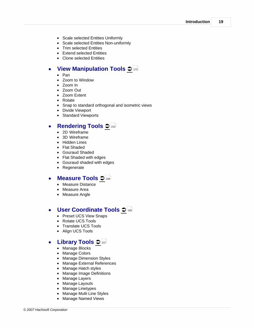
Introduction 19
© 2007 Hachisoft Corporation
· Scale selected Entities Uniformly· Scale selected Entities Non-uniformly· Trim selected Entities· Extend selected Entities· Clone selected Entities
· View Manipulation Tools Ü· Pan· Zoom to Window· Zoom In· Zoom Out· Zoom Extent· Rotate · Snap to standard orthogonal and isometric views· Divide Viewport· Standard Viewports
· Rendering Tools Ü· 2D Wireframe · 3D Wireframe · Hidden Lines · Flat Shaded· Gouraud Shaded · Flat Shaded with edges· Gouraud shaded with edges· Regenerate
· Measure Tools Ü· Measure Distance · Measure Area · Measure Angle
· User Coordinate Tools Ü· Preset UCS View Snaps· Rotate UCS Tools· Translate UCS Tools· Align UCS Tools
· Library Tools Ü· Manage Blocks· Manage Colors· Manage Dimension Styles· Manage External References· Manage Hatch styles· Manage Image Definitions· Manage Layers· Manage Layouts· Manage Linetypes· Manage Multi Line Styles· Manage Named Views
173
213
244
193
217

hsCADCreator Help20
© 2007 Hachisoft Corporation
· Manage Plot Settings· Manage Text Styles· Manage User Coordinate Systems· Manage Viewports· Quick Layer View
2 Handbook
Designing and drafting with the aid of a computer is equal parts art and craft. hsCADCreator seeksto facilitate the precision and practicality of CAD while still maintaining an enjoyable user experience.The following handbook details aspects of the art and craft of CAD.
· Concepts - Background information and introductive CAD theory.
· User Interface - The visual components of the hsCADCreator design interface, what they do,and why. Describes all Tools , Toolbars , Menus , and Dialogs in detail.
· Files and Formats - Details on what file types, formats, and versions that are supported in thisapplication, as well as compatibility details.
2.1 Concepts
hsCADCreator employs specific concepts to facilitate drawing creation, editing and viewing:
Entities : Various types of entities that can be drawn.
Objects : Information holders for easy access to stored data.
Snap PointSettings
: Ability to direct cursor to various points on an entity.
Entity GripPoints
: Each entity has one or more manipulation or grip points associated with it which allowthe user to change visual properties of the entity.
Grid : Display of equidistant points along X and Y axis for ease of drafting.
DrawingSettings
: Background color of drawing screen, Units, etc. settings for active drawing.
Data TypesandProperties
: Various types of information commonly used in drawings.
PropertyTrees
: Collection of properties displayed in tree structure.
Tools : hsCADCreator provides a number of ways to easily create/edit/delete/manage allentities, objects, and their properties.
Toolbars : Collection of tools.
20
90
100 250 90 264
286
21
50
71
74
75
76
77
79
77
100
81

Handbook 21
© 2007 Hachisoft Corporation
Dialogs : Collection of various user interfaces to get done various complex tasks easily.
Undo/Redo
: Process to remove or reinstate last change made in drawing.
2.1.1 Entities
In hsCADCreator many distinct entities can be created in drawings.
1. Point
2. Line
3. Multi Line
4. 2D Polyline
5. 3D Polyline
6. Arc
7. Circle
8. Ellipse
9. Dimension
10.Text
11.Hatch
12.Poly Face Mesh
13.Block Definition
14.Block Insertion
15. Image Definition
16. Image Insertion
17.Viewport
All above entities(except Block Definition and Image Definition Entities) have some common propertiesthat can be set at the time of creation or modified by selecting entity/ies in the drawing. These commonproperties are:
Field Name Data Type Description
Color ColorColor of the pen with which thisentity gets drawn.
Layer LayerWeight(Width) of the pen withwhich this entity gets drawn
Lineweight Scientific DataImaginary transparent drawingsheet on which this entity getsdrawn.
Linetype Scale Scientific DataScaling factor for line type beingused.
Linetype Line TypeType of the pen (dotted, dashed,dot-dash-dot, etc.) with whichthis entity gets drawn.
88
89
22
23
24
26
27
28
30
32
33
43
45
46
61
46
63
144
49
220
64
78
78
66

hsCADCreator Help22
© 2007 Hachisoft Corporation
In hsCADCreator above properties are shown in Selection Property Tree when any entity is
selected using Selection Tool .
2.1.1.1 Point
A point is an entity that has a location in space but no extent.
In hsCADCreator, a Point Entity consists of the following data in addition to the Common Data :
Property Name Data Type Description
Position3D Point (X, Y, Zcoordinates)
The point's location in space.
In hsCADCreator the above properties are shown in the Selection Property Tree when a pointentity is selected using Selection Tool .
259
101
21
77
259
101

Handbook 23
© 2007 Hachisoft Corporation
To draw a point:
Entity toolbar :
Tool Menu : Create Ä Point
See also:Point Tool
2.1.1.2 Line
A line, or straight line,hsCADCreator can be described as an (infinitely) thin, (infinitely) long,perfectly straight curve. The line provides the shortest connection between two points . A linesegment is a part of a line that is bounded by two end points . The line entity represents a linesegment in 3D space .
In hsCADCreator, a Line Entity is a line segment that consists of the following data in addition tothe Common Data :
Property Name Data Type Description
Starting Point3D Point (X, Y, Zcoordinates)
The point locations in space.
Ending Point3D Point (X, Y, Zcoordinates)
The point locations in space.
Length Scientific Data The distance of the line segment
251
97
105
22
22
17
21
77
77
78

hsCADCreator Help24
© 2007 Hachisoft Corporation
from one end point to the other
In hsCADCreator the above properties are shown in the Selection Property Tree when a lineentity is selected using the Selection Tool .
To draw a line:
Entity toolbar :
Tool Menu : Create Ä Line
See also:Line Tool
2.1.1.3 Multi Line
A Multi line is a one or more parallel lines drawn along a reference line. It allows easy editing/creation of parallel lines as a single entity.
259
101
251
97
106
23

Handbook 25
© 2007 Hachisoft Corporation
In hsCADCreator, a Multi line Entity consists of the following data in addition to the Common Data:
Property Name Data Type Description
Multi line style Mulit line style The point locations in space.
Justification
Multi-option combo box.Available options are:-Align top with cursor-Align center with cursor-Align bottom with cursor
Justification of parallel lines withrespect to the reference linedefined by cursor inputs.
Number of vertices Integer NumberTotal number of vertices in thismulit-line.
Closed BooleanWhen checked(true) joins startand end point of multi line withan extra multi line.
End Caps BooleanDraws end caps at the end ofmulti-line if specified in multi linestyle.
Start Caps BooleanDraws start caps at the start ofmulti-line if specified in multi linestyle.
In hsCADCreator the above properties are shown in the Selection Property Tree when a multiline entity is selected using Selection Tool .
To draw a Multi line:
Entity toolbar :
Tool Menu : Create Ä Multi Line
21
67
79
79
79
79
259
101
251
97

hsCADCreator Help26
© 2007 Hachisoft Corporation
See also:Multi Line Tool
2.1.1.4 Planar Polyline
A Planar Polyline is a continuous line composed of one or more line segments or arcsegments in a two dimensional space .
In hsCADCreator, the Planar Polyline Entity consists of the following data in addition to theCommon Data :
Property Name Data Type Description
End Point(s)3D Point (X, Y, Z coordinatesfor each point) on a single plane. The point locations in space.
Closed BooleanWhen checked(true) joins startand end point of polyline with anextra line.
In hsCADCreator the above properties are shown in Selection Property Tree when a planarpolyline is selected using Selection Tool . Currently the End Point(s) property is not available inproperty tree for editing, but End Point(s) can be edited using grip points shown on the drawingscreen.
108
23 23 28
17
21
77
79
259
101
74

Handbook 27
© 2007 Hachisoft Corporation
To draw a Planar Polyline:
Entity toolbar :
Tool Menu : Create Ä Polyline Ä Planar (2D)
See also:2D Polyline Tool
2.1.1.5 3D Polyline
A 3D polyline is a continuous line composed of one or more line segments in a threedimensional space .
In hsCADCreator, the 3D Polyline Entity consists of the following data in addition to the CommonData :
251
97
110
23 23
17
21

hsCADCreator Help28
© 2007 Hachisoft Corporation
Property Name Data Type Description
End Point(s)3D Point (X, Y, Z coordinatesfor each point)
The point locations in space.
Closed BooleanWhen checked(true) joins startand end point of polyline with anextra line.
In hsCADCreator the above properties are shown in the Selection Property Tree when a 3Dpolyline is selected using Selection Tool . Currently the End Point(s) property is not available inthe property tree for editing, but End Point(s) can be edited using grip points shown on the drawingscreen.
To draw a 3D Polyline:
Entity toolbar :
Tool Menu : Create Ä Polyline Ä Non-Planar (3D)
See also:3D Polyline Tool
2.1.1.6 Arc
An arc entity is a continuous portion of a circle ; part of a circle's circumference (also called a circlesegment).
77
79
259
101
74
251
97
112
30

Handbook 29
© 2007 Hachisoft Corporation
In hsCADCreator, the Arc Entity consists of the following data in addition to the Common Data :
Property Name Data Type Description
Center Point3D Point (X, Y, Zcoordinates)
Center point of the circle thatthis arc represents.
Starting AngleScientific Data (degrees,radians)
Angle of origin of the arc inrelation to the Cartesian plane(360 degrees)
Ending AngleScientific Data (degrees,radians)
Angle of completion of the arc inrelation to the Cartesian plane(360 degrees)
Radius Scientific Data
The line segment distance fromthe arc's center to any point onthe arc
Start Point3D Point (X, Y, Zcoordinates)
Starting point of arc.
Through Point3D Point (X, Y, Zcoordinates)
Any point on this arc. Initially,this point is set to be equal toMid Point. When this property ischanged, arc is recalculatedsuch that it passes through StartPoint, new Through Point andEnd Point. Mid Point isrecalculated and Through Pointis also updated to be equal toMid Point.
Mid Point3D Point (X, Y, Zcoordinates)
Mid point on arc between StartPoint and End Point.
End Point3D Point (X, Y, Zcoordinates)
Ending point of arc.
In hsCADCreator above properties are shown in the Selection Property Tree when an arc entityis selected using the Selection Tool .
21
77
78
78
78
77
77
77
77
259
101

hsCADCreator Help30
© 2007 Hachisoft Corporation
To draw an Arc:
Entity toolbar :
Arc(Start-Center-End)
Arc(Start-Center-Angle)
Arc(Start-Center-Chord Length)
Arc(Start-Middle-End)
Tool Menu : Create Ä Arc Ä Start - Center - End
Ä Start - Center - Angle
Ä Start - Center - Chord Length
Ä Start - Middle - End
See also:Start-Center-End Arc ToolStart-Center-Angle Arc ToolStart-Center-Chord Length Arc ToolStart-Middle-End Arc Tool
2.1.1.7 Circle
A circle is an entity that is the set of all points on a plane at a fixed distance, called the radius, from afixed point, the center.
251
115
117
119
114
97
115
117
119
114

Handbook 31
© 2007 Hachisoft Corporation
In hsCADCreator, a Circle Entity consists of the following data in addition to the Common Data :
Property Name Data Type Description
Center Point3D Point (X, Y, Zcoordinates)
The point's location in space
Radius Scientific DataThe distance of the line segmentfrom the circle's center to anypoint on the circle.
In hsCADCreator the above properties are shown in the Selection Property Tree when a circleentity is selected using the Selection Tool .
To draw a Circle:
Entity toolbar :
Tool Menu : Create Ä Circle
See also:Circle Tool
21
77
78
259
101
251
97
120

hsCADCreator Help32
© 2007 Hachisoft Corporation
2.1.1.8 Ellipse
An ellipse is a plane algebraic curve (sometimes called an oval) where the sum of the distances fromany point on the curve to two fixed points is constant. The two fixed points are called foci (plural offocus). An ellipse is a type of conic section: if a conical surface is cut with a plane which does notintersect the cone's base, the intersection of the cone and plane is an ellipse. The line segment whichpasses through the foci and terminates on the ellipse is called the major axis. The major axis is alongthe longest segment that passes through the ellipse. The line which passes through the center(halfway between the foci), at right angles to the major axis, is called the minor axis.
In hsCADCreator, an Ellipse Entity consists of the following data in addition to the Common Data:
Property Name Data Type Description
Center Point3D Point (X, Y, Zcoordinates)
The point's location in space.
Major Axis3D Vector (X, Y, Zcoordinates) The major axis of ellipse.
Start Angle Scientific DataStart angle with reference tomajor axis.
End Angle Scientific DataEnd angle with reference tomajor axis.
Radius RatioReal Number (between 0 and1)
Ratio of Minor Axis Length/MajorAxis Length
In hsCADCreator the above properties are shown in the Selection Property Tree when an ellipseentity is selected using the Selection Tool .
21
77
78
78
78
78
259
101

Handbook 33
© 2007 Hachisoft Corporation
To draw an Ellipse:
Entity toolbar :
Tool Menu : Create Ä Ellipse
See also:Ellipse Tool
2.1.1.9 Dimension
A dimension is a parameter or measurement required to define the characteristics of an object — ie.length, width, and height or size and shape. Dimension entities are used to show different type of
measurements for various entities. In hsCADCreator, there are six type of Dimension Entities:
1. Aligned Dimension 2. Linear Dimension 3. Ordinate Dimension 4. Radial Dimension 5. Diametric Dimension 6. Angular Dimension
Each of these six dimension entities have some common properties in addition to their individualproperties. These common properties are as follows:
Property Name Data Type Description
Common properties from Entities:
Line Color ColorColor of the pen with which thisentity gets drawn.
251
97
121
35
36
38
39
41
42
220

hsCADCreator Help34
© 2007 Hachisoft Corporation
Line Weight Real NumberWeight(Width) of the pen withwhich this entity gets drawn
Layer LayerImaginary transparent drawingsheet on which this entity getsdrawn.
Line Type Line TypeType of the pen (dotted, dashed,dot-dash-dot, etc.) with whichthis entity gets drawn.
Line Type Scale Real NumberScaling factor for line type beingused.
Common properties from Dimension:
Use Dimension Style only Boolean
When checked it usesDimension Properties defined indimension style and does notuse local properties as override.
Dimension Style Dimension StylePre-created dimension style thatdefines various properties fordimension entities.
Dimension Properties Dimension Style
Local dimension style thatdefines various properties fordimension entities that canoverride properties defined bypre created dimension style.
In hsCADCreator the above properties are shown in the Selection Property Tree when adimension entity is selected using the Selection Tool .
To draw a Dimension:
Entity toolbar :
78
64
66
78
79
51
51
259
101
251

Handbook 35
© 2007 Hachisoft Corporation
Aligned Dimension
Linear Dimension
Ordinate Dimension
Radial Dimension
Diametric Dimension
Angular Dimension
Tool Menu : Create Ä Dimension Indicator ÄAligned
ÄLinear
ÄOrdinate
ÄRadial
ÄDiametric
ÄAngular
See also:Aligned Dimension ToolLinear Dimension ToolOrdinate Dimension Tool Radial Dimension Tool Diametric Dimension ToolAngular Dimension Tool
2.1.1.9.1 Aligned Dimension
Aligned Dimension is used for displaying and measuring length along any given linear entity. As thename suggests it can be aligned along any direction. Generally, these dimensions are used to
show absolute lengths along any direction.
In hsCADCreator, an Aligned Dimension Entity consists of the following data in addition to theEntity Common Data and the Dimension Common Data :
Property Name Data Type Description
Start Point3D Point (X, Y, Zcoordinates)
Starting point for measuringlength.
End Point3D Point (X, Y, Zcoordinates)
Ending point for measuringlength.
124
126
128
130
132
134
97
124
126
128
130
132
134
33
21 33
77
77

hsCADCreator Help36
© 2007 Hachisoft Corporation
Offset Point3D Point (X, Y, Zcoordinates)
Reference point wheredimension entity should bedrawn.
In hsCADCreator the above properties are shown in the Selection Property Tree when analigned dimension entity is selected using the Selection Tool .
To draw an Aligned Dimension:
Entity toolbar :
Tool Menu : Create Ä Dimension Indicator ÄAligned
See also:Aligned Dimension Tool
2.1.1.9.2 Linear Dimension
Linear Dimension is used for displaying and measuring length along X or Y axis. As the namesuggests it can only be aligned along the X or Y axis. Generally, these dimensions are used to showabsolute lengths along the X or Y axis.
77
259
101
251
97
124

Handbook 37
© 2007 Hachisoft Corporation
In hsCADCreator, a Linear Dimension Entity consists of the following data in addition to the EntityCommon Data and the Dimension Common Data :
Property Name Data Type Description
Start Point3D Point (X, Y, Zcoordinates)
Starting point for measuringlength.
End Point3D Point (X, Y, Zcoordinates)
Ending point for measuringlength.
Offset Point3D Point (X, Y, Zcoordinates)
Reference point wheredimension entity should bedrawn.
In hsCADCreator the above properties are shown in the Selection Property Tree when a lineardimension entity is selected using the Selection Tool .
21 33
77
77
77
259
101

hsCADCreator Help38
© 2007 Hachisoft Corporation
To draw an Linear Dimension:
Entity toolbar :
Tool Menu : Create Ä Dimension Indicator ÄLinear
See also:Linear Dimension Tool
2.1.1.9.3 Ordinate Dimension
Ordinate Dimensions are used for measuring the length along any X or Y axis and displaying lengthas a text with the use of a leader. Generally, these dimensions are used to show lengths of entitiesusing leader lines.
In hsCADCreator, an Ordinate Dimension Entity consists of the following data in addition to theEntity Common Data and the Dimension Common Data :
Property Name Data Type Description
Origin Point3D Point (X, Y, Zcoordinates)
Starting point for measuringlength.
Defining Point3D Point (X, Y, Zcoordinates)
Ending point for measuringlength.
Leader End Point 3D Point (X, Y, Z Reference point where
251
97
126
21 33
77
77
77

Handbook 39
© 2007 Hachisoft Corporation
coordinates)dimension entity should bedrawn.
On X-axis BooleanIf checked(true) showsdimension text along X-axis,else shows it along Y-axis.
In hsCADCreator the above properties are shown in the Selection Property Tree when anordinate dimension entity is selected using the Selection Tool .
To draw an Ordinate Dimension:
Entity toolbar :
Tool Menu : Create Ä Dimension Indicator ÄOrdinate
See also:Ordinate Dimension Tool
2.1.1.9.4 Radial Dimension
Radial Dimensions are used for measuring the radius of arcs , circles , and ellipses anddisplaying it with a leader line.
79
259
101
251
97
128
28 30 32

hsCADCreator Help40
© 2007 Hachisoft Corporation
In hsCADCreator, a Radial Dimension Entity consists of the following data in addition to the EntityCommon Data and the Dimension Common Data :
Property Name Data Type Description
Center Point3D Point (X, Y, Zcoordinates)
Center point of arc, ellipse,circle.
Chord Point3D Point (X, Y, Zcoordinates)
Point on circumference of arc,ellipse, circle.
Leader Length Real Number Length of leader line.
In hsCADCreator the above properties are shown in the Selection Property Tree when a radialdimension entity is selected using the Selection Tool .
21 33
77
77
78
259
101

Handbook 41
© 2007 Hachisoft Corporation
To draw an Radial Dimension:
Entity toolbar :
Tool Menu : Create Ä Dimension Indicator ÄRadial
See also:Radial Dimension Tool
2.1.1.9.5 Diametric Dimension
Diametric Dimensions are used for measuring the diameter or chord of a circle or ellipse andshowing it with a leader lines.
In hsCADCreator, a Diametric Dimension Entity consists of the following data in addition to theEntity Common Data and the Dimension Common Data :
Property Name Data Type Description
Near Chord Point3D Point (X, Y, Zcoordinates)
Near chord point oncircumference of arc, ellipse,circle.
Far Chord Point3D Point (X, Y, Zcoordinates)
Far chord point oncircumference of arc, ellipse,circle.
Leader Length Real Number Length of leader line.
In hsCADCreator the above properties are shown in the Selection Property Tree when adiametric dimension entity is selected using the Selection Tool .
251
97
130
30 32
21 33
77
77
77
259
101

hsCADCreator Help42
© 2007 Hachisoft Corporation
To draw an Diametric Dimension:
Entity toolbar :
Tool Menu : Create Ä Dimension Indicator ÄDiametric
See also:Diametric Dimension Tool
2.1.1.9.6 Angular Dimension
Angular Dimensions are used for measuring and displaying inside and outside angles.
In hsCADCreator, an Angular Dimension Entity consists of the following data in addition to theEntity Common Data and the Dimension Common Data :
251
97
132
21 33

Handbook 43
© 2007 Hachisoft Corporation
Property Name Data Type Description
Center Point3D Point (X, Y, Zcoordinates)
Center point for anglemeasurement
Arc Point3D Point (X, Y, Zcoordinates)
Offset point where angle textshould be displayed
Line 1 Point3D Point (X, Y, Zcoordinates)
Point on line measuring angle
Line 2 Point3D Point (X, Y, Zcoordinates)
Point on line measuring angle
In hsCADCreator the above properties are shown in the Selection Property Tree when anangular dimension entity is selected using the Selection Tool .
To draw an Angular Dimension:
Entity toolbar :
Tool Menu : Create Ä Dimension Indicator ÄAngular
See also:Angular Dimension Tool
2.1.1.10 Text
A Text Entity is the body of printed or written matter on a drawing.
77
77
77
77
259
101
251
97
134
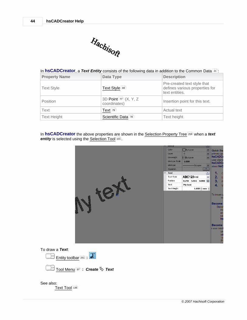
hsCADCreator Help44
© 2007 Hachisoft Corporation
In hsCADCreator, a Text Entity consists of the following data in addition to the Common Data :
Property Name Data Type Description
Text Style Text StylePre-created text style thatdefines various properties fortext entities.
Position3D Point (X, Y, Zcoordinates)
Insertion point for this text.
Text Text Actual text
Text Height Scientific Data Text height
In hsCADCreator the above properties are shown in the Selection Property Tree when a textentity is selected using the Selection Tool .
To draw a Text:
Entity toolbar :
Tool Menu : Create Ä Text
See also:Text Tool
21
69
77
79
78
259
101
251
97
136

Handbook 45
© 2007 Hachisoft Corporation
2.1.1.11 Hatch
Hatching and cross-hatching are artistic techniques used to create tonal or shading effects bydrawing closely spaced parallel lines. When lines are placed at an angle to one another, it is called cross-hatching. Mostly hatch entities are used to show a cross-sectional view in a drawing.
In hsCADCreator, a Hatch Entity consists of the following data in addition to the Common Data :
Property Name Data Type Description
Hatch Style Hatch StyleHatch Style used to draw thishatch entity.
In hsCADCreator the above properties are shown in the Selection Property Tree when a hatchentity is selected using the Selection Tool .
To draw a Hatch:
Entity toolbar :
21
60
259
101
251

hsCADCreator Help46
© 2007 Hachisoft Corporation
Tool Menu : Create Ä Hatch
See also:Hatch Tool
2.1.1.12 Poly Face Mesh
Poly face mesh entity is a solid face entity that is created by meshing polylines together. Viewingpoly face mesh entities using Gouraud Shaded Tool , Flat Shaded Tool , or Hidden Tool ,displays them as solid surfaces.
In hsCADCreator, a Poly face mesh does not have any special data different than Entity data .
To draw a Poly face mesh:
Entity toolbar :
Tool Menu : Create Ä Poly Face Mesh
See also:Poly Face Mesh Tool
2.1.1.13 Block Reference
Block Reference/Insertion entities represents copies of Block Definitions . In hsCADCreator,the Block Insertion Tool is used to create block insertion entities from block definitions. Forexample, if the user frequently created drawings with a particular design of door, he/she could make a block (or stamp) of door and add it to Block Library using Block Creation Tool , and insert itwhenever his/her drawing called for it. Each door would look exactly like the others and would give thedrawing a consistent appearance.
97
138
26
215 214 214
21
251
97
139
61
142
218 140

Handbook 47
© 2007 Hachisoft Corporation
In hsCADCreator, a Block Insertion Entity consists of the following data in addition to the CommonData :
Property Name Data Type Description
Block Name Block DefinitionName of block definition used tocreate this block insertion.
Insertion Point3D Point (X, Y, Zcoordinates)
The block's reference base pointfor insertions.
Scale Factors3D Point (X, Y, Z scalefactors)
Scaling factors along X, Y and Zaxis
Rotation Scientific DataAngle of rotation about InsertionPoint
In hsCADCreator the above properties are shown in the Selection Property Tree when a blockinsertion entity is selected using the Selection Tool .
To draw a Block into drawing from Block Library:
Entity toolbar :
Tool Menu : Create Ä Block Insertion
See also:Library WindowBlock EntityManage BlocksBlock Insertion Tool
2.1.1.14 Image Insertion
Image Insertion Entity represents copies of Image Definitions that are inserted in drawing.Copies of Image Entities can be inserted into a drawing using the Image Insertion Tool . To insert
21
61
77
77
78
259
101
251
97
282
61
218
142
63
144

hsCADCreator Help48
© 2007 Hachisoft Corporation
an Image Entity, it is required that the image definition exists in Image Library . Image definitionsare added to the Image Library using the Manage Image Definitions Tool .
In hsCADCreator, a Image Insertion Entity consists of the following data in addition to theCommon Data :
Property Name Data Type Description
Origin Point3D Point (X, Y, Zcoordinates)
The Image's reference basepoint for insertions.
Dimension2D Point (X, Y size realnumbers)
Size of Image.
Rotation Angle Scientific DataAngle of rotation about InsertionPoint
File Name TextFull path including filename withextension for image.
Show Image BooleanIf checked(true) shows actualimage, else shows only borderfor the image.
Unaligned BooleanIf checked(true) shows imageunaligned.
Clip Image BooleanIf checked(true) clips image toborders, else leaves imageunclipped.
Transparent Image BooleanIf checked(true) makes imagetransparent.
In hsCADCreator the above properties are shown in the Selection Property Tree when an imageinsertion entity is selected using the Selection Tool .
228
228 228
21
77
77
78
79
79
79
79
79
259
101

Handbook 49
© 2007 Hachisoft Corporation
To insert an Image into drawing from the Image Library :
Entity toolbar :
Tool Menu : Create Ä Image Insertion
See also:Insert Image ToolImage EntityManage Image Definitions
2.1.1.15 Paperspace Viewport
Paperspace Viewport Entity is a rectangular entity through which a 3D scene can be shown. InhsCADCreator, Paperspace Viewport Entity shows a view of the 3D Modelspace. Paperspace
Viewport Entity can only be created on a paperspace layout. By default, hsCADCreator createstwo paperspace layouts with all new drawings. They are named "layout1" and "layout2". To
facilitate viewing of drawing through multiple viewports in Modelspace, hsCADCreator utilizes pre-set multiple viewports through Pre-configured Viewport Tool . Depending on whether the viewportexists on Modelspace or Paperspace they are defined as Modelspace viewport object andPaperspace viewport entity.
In hsCADCreator, a Paperspace Viewport Entity consists of the following data:
Property Name Data Type Description
On Boolean Turns on/off this viewport entity.
Camera Settings Multiple option selection box.Sets the camera settings for thisviewport entity.
Center 3D PointCenter point for this viewportentity.
Width Scientific Data Width of viewport
Height Scientific Data Height of viewport
Transparency(%) Real NumberSpecifies transparency value forthis viewport object.
In hsCADCreator the above properties are shown in the Selection Property Tree when apaperspace viewport entity is selected using the Selection Tool .
228
251
97
144
63
228
64
186
70
79
79
78
78
78
78
259
101

hsCADCreator Help50
© 2007 Hachisoft Corporation
To insert a paperspace viewport into drawing from the Viewport Library :
Entity toolbar :
Tool Menu : Create Ä Viewport
See also: Create Viewport Entity Divide Viewport Tool Pre-configured Viewport Tool
2.1.2 Objects
Objects are information holders in hsCADCreator. Objects allows easy access to stored non-
graphical data. There are total 11 types of objects in hsCADCreator. Visit the link on each objectbelow for more information
1.
2.
3.
4.
5.
6.
7.
8.
9.
10.
Colors
Dimension Styles
Draw Plane (UCS)
External References
Hatch Style
Layers
Layouts
Linetypes
Plot Settings
Text Styles
242
251
97
49
184
186
51
51
59
223
60
64
64
66
238
69
Handbook 51
© 2007 Hachisoft Corporation
11.Multiline Styles
2.1.2.1 Colors
Color Objects store color information in hsCADCreator. Color Objects are used to represent
colors of background, layer, line color, etc. hsCADCreator creates nine colors on every drawing:Red, Green, Yellow, Cyan, Blue, Magenta, Foreground, Dark Background and Light Background.
In hsCADCreator, a Color Object consists of the following data:
Property Name Data Type Description
Color Method Multi-option selection boxColor method to be used for thiscolor object
Red Integer Number Amount of red color.
Green Integer Number Amount of green color.
Blue Integer Number Amount of blue color.
Name Text Name of this color to save as.
Description Text Description for this color.
Explanation Text Explanation for this color.
To create Color Objects :
Library toolbar :
Manage Menu : Colors...
2.1.2.2 Dimension Styles
Dimension Style Objects represent formatting information for all dimension entities inhsCADCreator. Dimension Style can be applied to dimension entities to have similar look andfeel across all dimension entities in a drawing.
In hsCADCreator, a Dimension Style Object consists of the following data:
Property Name Data Type Description
Dimension Styles Properties:
Arc Symbol Type
Multiple options combo box..Available options are: -Arc symbol precedes text. -Arc symbol is above text. -No arc symbol.
Sets the arc symbol type.
Text BG Color ColorSets the background color fortext.
Extension line-1 Linetype LinetypeSets the first extension linelinetype.
67
79
78
78
78
79
79
79
217
96
33
33
33
79
51
66

hsCADCreator Help52
© 2007 Hachisoft Corporation
Extension line-2 Linetype LinetypeSets the second extension linelinetype.
Dimension line Linetype Linetype Sets the dimension line linetype.
Extension Line Fix LengthEnabled
BooleanControls if the extension line hasa fixed length.
Extension Line Fix Length Scientific DataSets the extension line fixedlength.
Flip Arrow
Multiple options combo box..Available options are:-One arrow outside firstextension line-One arrow outside secondextension line-Arrows inside extension lines-Arrows outside extension lines
Sets the arrow flip option.
Jog Angle Scientific Data Sets the jog angle.
Dimension Line and Leader line properties:
Hide first dimension line andarrow-head
BooleanShow/hide first dimension lineand arrow-head.
Hide second dimension line andarrow-head
BooleanShow/hide second dimensionline and arrow-head.
Dimension line extension Scientific DataThe distance dimension linesextend beyond extension lines.
Dimension line distance Scientific DataThe distance betweendimension lines for baselinedimensions.
Dimension line Lineweight Scientific Data Lineweight for dimension lines
Hide dimension lines outsideextension lines
BooleanShow/Hide dimension linesoutside extension lines.
Draw dimension lines when textis outside dimension lines
BooleanShow/hide dimension linesbetween extension lines whentext is outside dimension lines.
Extension line properties:
Extension Lineweight Scientific Data Lineweight for extension lines
Hide first extension line Boolean Show/Hide first extension line.
Hide second extension line BooleanShow/Hide second extensionline.
Extension line extension Scientific DataThe distance extension linesextend beyond dimension lines.
Extension offset Scientific DataThe distance extension lines areoffset from their origin points.
Dimension text properties:
Decimal separator Text
Decimal separator formeasurements. This value mustbe single character. If more thanone characters are specified,
66
66
79
78
79
78
79
79
78
78
78
79
79
78
79
79
78
78
79

Handbook 53
© 2007 Hachisoft Corporation
application considers the firstcharacter as decimal separator.
Text style Text Style Text style for dimension text.
Text size Scientific Data
Specify size of the dimensiontext. If text style being used has"Fix Size" variable set to TRUEthen text size has no effect ondimension text.
Text horizontal position
Multiple options combo box..Available options are:-Centered above the dimensionline. -By the first extension line. -By the second extension line. -Above the dimension line,parallel to the first extensionline. -Above the dimension line,parallel to the second extensionline.
Sets dimension text's horizontalposition.
Text vertical position
Multiple options combo box..Available options are:-Centered about the dimensionline. -Above the dimension line,unless DIMTIH=1 and thedimension line is not horizontal. -Side of the dimension linefarthest from the defining points. -JIS standard.
Sets dimension text's verticalposition.
Dimension type
Multiple options combo box.Available options are:-Scientific -Decimal -Engineering -Architectural (stacked) -Fractional (stacked) -Microsoft Windows Desktop
Sets dimension formatting typefor units in non-angulardimensions.
Decimal places Integer Number Number of decimal places
Zero suppression in lineardimensions
Multiple options combo box.Available options are:-Suppress zero feet and exactlyzero inches. -Include zero feet and exactlyzero inches. -Include zero feet and suppressexactly zero inches. -Suppress zero feet and includeexactly zero inches. -Suppress trailing decimalzeros. -Suppress leading decimalzeros.
Sets zero suppression optionsfor linear dimension values.
69
78
79
79
79
78
79

hsCADCreator Help54
© 2007 Hachisoft Corporation
Prefix and/or suffixText
Specify prefix and/or suffix formeasurement text. The syntax isMy Prefix<>MySuffix. Here"MyPrefix" is the prefix userwants to prepend beforedimension value and "MySuffix"is the suffix user wants toappend after dimension value."<>" gets replaced by actualdimension value whendimension entity is created.e.g. <>in will be replaced by 10inwhen dimension entity iscreated.<>" will be replaced by 10" whendimension entity is created.@<> cm will be replaced by@10cm when dimension entityis created.
Text rounding Real Number
Sets the rounding ofmeasurements. If value is 0, norounding is performed, else themeasurement text is rounded tonearest multiple of roundingvalue specified.e.g.If measurement value is 8.81and Number of Decimal placesis set to 2, Rounding value = 0.000 willmake measurement value 8.81.Rounding value = 1.000 willmake measurement value 9.00Rounding value = 2.000 willmake measurement value 8.00Rounding value = 5.000 willmake measurement value 10.00Rounding value = 1.100 willmake measurement value 8.80Rounding value = 5.200 willmake measurement value 10.40
Make inside text X-aligned Boolean
Controls the orientation ofdimension text inside theextension lines. If checkedmakes text aligned with WCS X-axis otherwise aligns withdimension line.
Make outside text X-aligned Boolean
Controls the orientation ofdimension text outside theextension lines. If checkedmakes text aligned with WCS X-axis otherwise aligns withdimension line.
Force dimension text to put Boolean If checked it always puts
79
78
79
79
79

Handbook 55
© 2007 Hachisoft Corporation
inside extension linesdimension text inside extensionlines, otherwise it puts insideonly if there is room.
Text movement rules
Multiple options combo box.Available options are:-Dimension line moves withdimension text. -Adds a leader for moveddimension text.-No leader, moves onlydimension text.
Sets movement rules for thedimension text.
Dimension text gap(factor) Real Number
The vertical distance frommiddle of the dimension text tothe dimension line. This value isspecified as factor of dimensiontext size.
Tolerance and fraction properties:
Fraction format
Multiple options combo box..Available options are:-Horizontal Stacked. -Diagonal Stacked. -Not Stacked.
Sets the fraction format whendimension type is architectural orfractional. This value has noeffect if "Dimension type" under"Dimension text properties" isnot architectural or fractional.
Show tolerance Boolean Show/hide tolerance text.
Tolerance and fraction text size Real NumberThe size of tolerance andfraction text as a factor ofDimension text size.
Tolerance vertical position
Multiple options combo box.Available options are:-Centered about the dimensionline. -Above the dimension line,unless DIMTIH=1 and thedimension line is not horizontal. -Side of the dimension linefarthest from the defining points. -JIS standard.
Controls vertical position ofTolerance with respect todimension line.
Lower tolerance limit Real Number Sets lower tolerance limit.
Upper tolerance limit Real Number Sets upper tolerance limit.
Note: Since all decimal numbers are controlled by Application Settings variable "Decimal Places", ifyou want to specify tolerance limits with more decimal precision, change "Decimal Places" variable in
Application settings. This can be accessed by following Menu: Options Æ Application settings...
Zero suppression in tolerancevalues
Multiple options combo box.Available options are:-Suppress zero feet and exactlyzero inches. -Include zero feet and exactlyzero inches. -Include zero feet and suppressexactly zero inches. -Suppress zero feet and include
Sets zero suppression intolerance values.
79
78
79
79
78
79
78
78
79

hsCADCreator Help56
© 2007 Hachisoft Corporation
exactly zero inches. -Suppress trailing decimalzeros. -Suppress leading decimalzeros.
Decimal places in tolerance Integer NumberNumber of decimal place intolerance values.
Dimension color properties:
Dimension Color ColorColor of dimension line, arrow-head, leader lines.
Extension Color Color Color of extension lines
Text Color Color Color of dimension texts
Angular dimension properties:
Precision(Angle) Integer NumberDecimal places in angularmeasurements
Suppress zero(Angular)
Multiple options combo box.Available options are:-Suppress zero feet and exactlyzero inches. -Include zero feet and exactlyzero inches. -Include zero feet and suppressexactly zero inches. -Suppress zero feet and includeexactly zero inches. -Suppress trailing decimalzeros. -Suppress leading decimalzeros.
Sets zero suppression in angulardimensions.
Arrow-head properties:
Arrow-head size Scientific DataArrow-head size in dimensionentities.
Arrow, Text Fit
Multiple options combo box.Available options are:-Moves text and arrows outsideextension lines. -Moves arrows, then text,outside extension lines. -Moves text, then arrows,outside extension lines. -Moves text or arrows for bestfit.
Arrow and Text fit in dimensions.This property specifies howarrows and text are placed whenthey do not fit within theextension lines of dimensions.
Custom Arrow-head block Block Definition
Specify custom arrow-headblock at ends of dimension andleader lines. If not specified it willuse default arrow-head.
Separate arrow-heads BooleanUse separate arrow-heads fordimension lines.
First Custom Arrow-head block Block Definition Specify first custom arrow-head
78
51
51
51
78
79
78
79
61
79
61

Handbook 57
© 2007 Hachisoft Corporation
block of dimension lines. If notspecified it will use defaultarrow-head. If "Separate arrow-heads" is not selected, thisproperty has no effect ondimension entities.
Second Custom Arrow-headblock
Block Definition
Specify second custom arrow-head block of dimension lines. Ifnot specified it will use defaultarrow-head. If "Separate arrow-heads" is not selected, thisproperty has no effect ondimension entities.
Leader line custom arrow block Block Definition
Specify the arrowhead block atthe end of leader lines. If notspecified it will use defaultarrowhead.
Miscellaneous properties:
Arc/Circle center mark Real Number
The absolute value specifies thesize of the center mark. -vevalue: Center marks and centerlines shown. 0 value: No centermarks or center lines. +ve value:only Center marks are shown.
Move dimension line and thetext
BooleanIf checked moves dimension lineand the text, otherwise only thedimension line.
Dimension line and text gap Scientific DataThe gap between dimension textand dimension lines. -ve valuedraws a box around text.
Linear scale factor Scientific DataScale Factor for lineardimension.
Construct dimension limits Boolean Construct dimension limits
Overall scale factor Real NumberScale factor for whole dimensionblock.
Alternate dimension properties:
Use alternate measurements BooleanEnables alternatemeasurements in dimensions.
Alternate dimension type
Multiple options combo box.Available options are:-Scientific -Decimal -Engineering -Architectural (stacked) -Fractional (stacked) -Microsoft Windows Desktop
Sets alternate measurementtype.
Zero suppression in alternatemeasurements
Multiple options combo box.Available options are:-Suppress zero feet and exactlyzero inches. -Include zero feet and exactly
Sets zero suppression inalternate measurements indimensions.
61
61
78
79
78
78
79
78
79
79
79

hsCADCreator Help58
© 2007 Hachisoft Corporation
zero inches. -Include zero feet and suppressexactly zero inches. -Suppress zero feet and includeexactly zero inches. -Suppress trailing decimalzeros. -Suppress leading decimalzeros.
Prefix and/or suffix for alternatemeasurements text
Text
Specify prefix and/or suffix foralternate measurement text. Thesyntax is MyPrefix<>MySuffix.Here "MyPrefix" is the prefixuser wants to prepend beforedimension value and "MySuffix"is the suffix user wants toappend after dimension value."<>" gets replaced by actualdimension value whendimension entity is created.e.g. <>in will be replaced by 10inwhen dimension entity iscreated.<>" will be replaced by 10" whendimension entity is created.@<> cm will be replaced by@10cm when dimension entityis created.
Number of decimal places Integer NumberNumber of decimal places inalternate measurements indimensions.
Distance multiplier Real NumberDistance multiplier for alternatemeasurements in dimensions.
Rounding specifier Real Number
Sets the rounding of alternatemeasurement. If value is 0, norounding is performed, else themeasurement text is rounded tonearest multiple of roundingvalue specified.e.g.If measurement value is 8.81and Number of Decimal placesis set to 2, Rounding value = 0.000 willmake measurement value 8.81.Rounding value = 1.000 willmake measurement value 9.00Rounding value = 2.000 willmake measurement value 8.00Rounding value = 5.000 willmake measurement value 10.00Rounding value = 1.100 willmake measurement value 8.80Rounding value = 5.200 willmake measurement value 10.40
79
78
78
78

Handbook 59
© 2007 Hachisoft Corporation
Number of decimal places intolerance
Integer NumberNumber of decimal places intolerance values in alternatemeasurements in dimensions.
Zero suppression in tolerance
Multiple options combo box.Available options are:-Suppress zero feet and exactlyzero inches. -Include zero feet and exactlyzero inches. -Include zero feet and suppressexactly zero inches. -Suppress zero feet and includeexactly zero inches. -Suppress trailing decimalzeros. -Suppress leading decimalzeros.
Sets zero suppression intolerance values in alternatemeasurements in dimensions.
To create Dimension Style:
Library toolbar :
Manage Menu : Dimension Styles...
2.1.2.3 User Coordinate System
User Coordinate System (UCS) is a user defined coordinate space. User can define multiplecoordinate systems and store them using Manage User Coordinate Systems . UCS is alwaysdefined with reference to WCS . At any given time, there is only one UCS active. The activeUCS can be modified using various UCS Tools .
In hsCADCreator, a User Coordinate System consists of the following data:
Property Name Data Type Description
Origin 3D Point(0, 0, 0) Origin Point for thisUser coordinate system
X-Axis Vector 3D VectorX-axis for this User CoordinateSystem
Y-Axis Vector 3D VectorY-axis for this User CoordinateSystem
To create User Coordinate System:
Library toolbar :
Manage Menu : User Coordinate System...
See also:Draw Plane/UCS ToolsManage User Coordinate Systems
78
79
217
96
17
241 17
17 17
17 193
78
78
78
217
96
193
241
hsCADCreator Help60
© 2007 Hachisoft Corporation
2.1.2.4 External References
External Reference Objects are references to external drawings. Using these objects, externaldrawing can be inserted into current drawing as a block.
In hsCADCreator, External Reference Objects consists of the following data:
Property Name Data Type Description
Name Text Name of external reference
IsNested BooleanChecked(true), if the externalreference has more externalreferences
IsResolved BooleanChecked(true), if the externalreference is loaded andresolved.
To create External Reference Objects :
Library toolbar :
Manage Menu : External Reference...
2.1.2.5 Hatch Style
Hatch Style objects represent the style used to draw a hatch entity . Hatch Style object representseither a hatch gradient or a hatch pattern .
In hsCADCreator, a Hatch Style consists of the following data:
Property Name Data Type Description
Preset Multi-option selection boxName of pattern or gradient
used for this hatch style.
Pattern or GradientHatch Pattern or HatchGradient
Detailed properties of pattern orgradient used for this hatchstyle.
There are two major types of Hatch Styles within hsCADCreator.
Hatch Pattern Styles
Hatch Gradient Styles
2.1.2.5.1 Hatch Gradients
Hatch Gradient Objects define color gradient for filling in area inside boundaries. Gradient color iscombination of two colors such that it starts off as first color on boundary and fades of to becomesecond color on boundary. Hatch Gradient Objects are used for hatch entities.
In hsCADCreator, a Hatch Gradient Object consists of the following data:
Field Name Data Type Description
79
79
79
217
96
45
60 61
7961
60
61
60
227
60
45

Handbook 61
© 2007 Hachisoft Corporation
Name TextName for this hatch gradientobject
Description Text Description for hatch gradient
Gradient Type Multiple options combo box.. Gradient direction type for hatchgradient object
Shift Real Number Offset shift distance.
Luminance Real NumberLuminance value for hatchgradient.
Start Color Color Starting color for gradient
End Color Color Ending color for gradient
Angle Real Number Angle for gradient
To create Hatch Gradient Objet:
Library toolbar :
Manage Menu : Hatch Style...
2.1.2.5.2 Hatch Patterns
Hatch Pattern Objects define patterns for filling in area inside boundaries. Hatch Pattern Objectsare used for hatch entities.
In hsCADCreator, a Hatch Pattern Object consists of the following data:
Field Name Data Type Description
Name TextName for this hatch gradientobject
Description Text Description for hatch gradient
Scale Real Number Scale for hatch pattern
Angle Real Number Angle for gradient
To create Hatch Pattern Object:
Library toolbar :
Manage Menu : Hatch Pattern...
2.1.2.6 Block Definition
Block Definition objects are collections of various drawn entities so that they can be copied morethan once. For example, if the user frequently created drawings with a particular design of door, he/shecould make a block (or stamp) of door and add it to Block Library using Block Creation Tool ,and insert it whenever his/her drawing called for it. Each door would look exactly like the others and
79
79
79
78
78
51
51
78
217
96
45
79
79
78
78
217
96
21
218 140
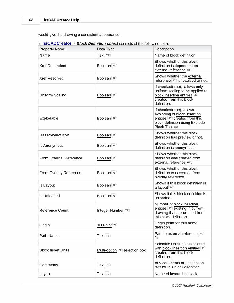
hsCADCreator Help62
© 2007 Hachisoft Corporation
would give the drawing a consistent appearance.
In hsCADCreator, a Block Definition object consists of the following data:
Property Name Data Type Description
Name Text Name of block definition
Xref Dependent BooleanShows whether this blockdefinition is dependent on external reference .
Xref Resolved BooleanShows whether the externalreference is resolved or not.
Uniform Scaling Boolean
If checked(true), allows onlyuniform scaling to be applied to block insertion entitiescreated from this blockdefinition.
Explodable Boolean
If checked(true), allowsexploding of block insertionentities created from thisblock definition using ExplodeBlock Tool .
Has Preview Icon BooleanShows whether this blockdefinition has preview or not.
Is Anonymous BooleanShows whether this blockdefinition is anonymous.
From External Reference BooleanShows whether this blockdefinition was created from external reference .
From Overlay Reference BooleanShows whether this blockdefinition was created fromoverlay reference.
Is Layout BooleanShows if this block definition isa layout .
Is Unloaded BooleanShows if this block definition isunloaded.
Reference Count Integer Number
Number of block insertionentities existing in currentdrawing that are created fromthis block definition.
Origin 3D PointOrigin point for this blockdefinition.
Path Name TextPath to external referencefile.
Block Insert Units Multi-option selection box
Scientific Units associatedwith block insertion entitiescreated from this blockdefinition.
Comments TextAny comments or descriptiontext for this block definition.
Layout Text Name of layout this block
79
79
60
7960
79 46
79 46
152
79
79
79
60
79
7964
79
7846
78
7960
79
78
46
79
79

Handbook 63
© 2007 Hachisoft Corporation
definition is associated with.
To add a new Block Definition to drawing's Block Library :
Entity toolbar :
Tool Menu : Create Ä Block
See also:Create Block ToolBlock Insertion EntityManage BlocksBlock Insertion Tool
2.1.2.7 Image Definition
Image Definition object represents all objects that can be defined by standard bitmap types (.jpg, .bmp, .tiff, .gif, .png, .rle, .dib). Image Definitions are stored in Image Library using Manage ImageDefinitions Tool . Stored Image Definitions can be inserted in drawing using Image Insertion Tool
.
In hsCADCreator, an Image Definition object consists of the following data:
Property Name Data Type Description
Image Resolution Real Number | Real NumberResolution of this imagedefinition in millimeters per pixel.Size of single pixel Width |Height in millimeters
Is Loaded BooleanShows whether the image file forthis image definition is loaded inmemory or not.
Size of Image Real Number | Real Number Image size in pixels Width |Height.
Source File TextPath to image file from whichthis image definition wascreated.
Resolution Units Multi-option selection boxResolution unit for this imagedefinition.
To add an Image Definition to drawing's Image Library :
Library toolbar :
Tool Menu : Manage Ä Image Definitions
See also:Image Insertion EntityManage Image Definitions
218
251
97
140
46
218
142
228
228
144
78
78
79
78
78
79
79
228
257
97
47
228

hsCADCreator Help64
© 2007 Hachisoft Corporation
2.1.2.8 Layers
Layer Objects can be described as invisible drawing sheets that can be activated to draw, turn off/onto see entities on that layer, etc.
In hsCADCreator, a Layer Object consists of the following data:
Property Name Data Type Description
Name TextName for this hatch gradientobject
Description Text Description for hatch gradient
Color ColorDefault color for entities drawnon this layer.
Lineweight Real NumberDefault lineweight for entitiesdrawn on this layer.
Linetype LinetypeDefault linetype for entitiesdrawn on this layer.
Frozen Boolean
If checked(true) freezes thislayer else thaw this layer.Entities on frozen layers are notvisible on screen. Entities onfrozen layer are not passed torendering engine.
Plottable BooleanIf checked(true) makes this layerplottable.
Off Boolean
If checked(true) turns this layerOFF. Entities on OFF layers arenot visible on screen but are stillpassed to rendering engine.
Locked Boolean
If checked(true) locks this layer.Entities on locked layers arevisible on screen but can not beedited.
To create Layer Object:
Library toolbar :
Manage Menu : Layers...
2.1.2.9 Layouts
Layout Objects represents virtual drawing sheets. User can create snapshots of model using viewportand create viewport tool into Layout Objects.
In hsCADCreator, a Layout Object consists of the following data:
Property Name Data Type Description
Name Text Plot Settings Name
79
79
51
78
66
79
79
79
79
217
96
70 146
79

Handbook 65
© 2007 Hachisoft Corporation
Paper Units Multiple options combo box.Units the paper sizewill be based on.
Printer - Printer Multiple options combo box.Selection of currentprinter/plottersavailable on system.
Printer - Paper Size Multiple options combo box.Selection of commonpaper/potter sizes
Printer - PropertiesPrinter Properties Dialog (
)
Launches printerconfiguration dialog.
Plot Rotation
Multiple options combo box.Choices include-Inverted Landscape-Inverted Portrait-Landscape-Portrait
Modification of plotorientation.
Plot Type
Multiple options combo box. Options include:-Display-Extents-Layout-Window
Selection of sourcetype to be printed/plotted
Paper Image Origin X Real Number
Paper Image Origin Y Real Number
ScaleScale Ratio Selection (
)
Plot Arrangement
Plot Centered BooleanCenter the printedarea on the paper.
Origin X Real NumberSet the printed area'sorigin X component.
Origin Y Real NumberSet the printed area'sorigin Y component.
Plot Style Support
Show Plot Styles BooleanView with the selectedplot style.
Plot Plot Styles BooleanPrint/Plot with theselected plot style.
Plot Style File SelectionSelection of a plotstyle file.
Advanced Plot Settings
Scale Lineweights BooleanAuto Scale theLineweights.
Plot Lineweights BooleanPrint/Plot with thelineweights set withinthe drawing
Layout
Layout Name Text User specified name
79
79
79
79
79
78
78
79
78
78
79
79
79
79
79

hsCADCreator Help66
© 2007 Hachisoft Corporation
for this layout.
Maximum Limits 2D PointMaximum limits forthis layout
Minimum Limits 2D PointMinimum limits for thislayout
Extent Maximum Point 3D PointMaximum Extent pointfor this layout
Extent Minimum Point 3D PointMinimum Extent pointfor this layout
Insertion Base 3D PointInsertion point for thislayout
Maximum GeometryExtents
3D PointMaximum geometryextent point for thislayout
Minimum GeometryExtents
3D PointMinimum geometryextent point for thislayout
To create Layout Object:
Library toolbar :
Manage Menu : Drawing Layout...
2.1.2.10 Linetypes
Linetype Objects define different types of lines to be used in drawing. Each Linetype defines apattern that is repeated over the length of drawn line.
In hsCADCreator, a Linetype Object consists of the following data:
Property Name Data Type Description
Name Text Name for this linetype object
Comments Text Description for linetype
Scaled to fit BooleanMakes this linetype scale to fitthe length
Dash count Integer NumberNumber of dashes in linetypepattern
Pattern length Real Number Total length of linetype pattern
To create Linetype Object:
Library toolbar :
Manage Menu : Linetype...
77
77
78
78
78
78
78
217
96
23
79
79
79
78
78
217
96

Handbook 67
© 2007 Hachisoft Corporation
2.1.2.11 Multi Line Style
Multi line style objects define different types of one or more parallel polylines to be used in adrawing. Each Multi line style object defines a pattern of parallel lines that is repeated over the lengthof drawn line. Multi line entities use multi line styles to create uniform looking multi lines in adrawing.
In hsCADCreator, a Multi line style object consists of the following data:
Property Name Data Type Description
Name TextName for this Multi Line Styleobject
Description TextDescription for this Multi LineStyle object
Fill Color BooleanIf checked(true) fills colorbetween cursor line andminimum offset line.
Fill color ColorColor to be filled when Fill Colorfield is checked(true).
Start Angle Scientific DataStarting angle for all parallellines.
End Angle Scientific DataEnding angle for all parallellines.
Miters BooleanIf checked(true), shows miter ateach vertex.
Start Inner Arcs BooleanIf checked(true), draws innerarcs at start point.
Start Round Caps BooleanIf checked(true), draws roundcaps at start point.
Start Square Caps BooleanIf checked(true), draws squarecaps at start point.
End Inner Arcs BooleanIf checked(true), draws innerarcs at end point.
End Round Caps BooleanIf checked(true), draws roundcaps at end point.
End Square Caps BooleanIf checked(true), draws squarecaps at end point.
Linetypes: (More than one line types can be added by pressing "Add" button. All linetypes are drawnparallel to each other at specified offset distance.) Each Line Type has following properties:
Line Type Line TypeType of the pen (dotted, dashed,dot-dash-dot, etc.) with whichthis entity gets drawn.
Offset Scientific Data Offset distance for this linetype.
Color ColorColor of the pen with which thislinetype gets drawn.
To create Multi line style Object:
Library toolbar :
24
79
79
79
220
78
78
79
79
79
79
79
79
79
66
78
220
217

hsCADCreator Help68
© 2007 Hachisoft Corporation
Manage Menu : Multi Line Styles...
2.1.2.12 Plot Settings
Plot Settings Objects represents a group of settings for printing drawings.
In hsCADCreator, a Plot Settings Objects consists of the following data:
Property Name Data Type Description
Name Text Plot Settings Name
Paper Units Multiple options combo box.Units the paper sizewill be based on.
Printer - Printer Multiple options combo box.Selection of currentprinter/plottersavailable on system.
Printer - Paper Size Multiple options combo box.Selection of commonpaper/potter sizes
Printer - PropertiesPrinter Properties Dialog (
)
Launches printerconfiguration dialog.
Plot Rotation
Multiple options combo box.Choices include-Inverted Landscape-Inverted Portrait-Landscape-Portrait
Modification of plotorientation.
Plot Type
Multiple options combo box. Options include:-Display-Extents-Layout-Window
Selection of sourcetype to be printed/plotted
Paper Image Origin X Real Number
Paper Image Origin Y Real Number
ScaleScale Ratio Selection (
)
Plot Arrangement
Plot Centered BooleanCenter the printedarea on the paper.
Origin X Real NumberSet the printed area'sorigin X component.
Origin Y Real NumberSet the printed area'sorigin Y component.
Plot Style Support
Show Plot Styles BooleanView with the selectedplot style.
Plot Plot Styles BooleanPrint/Plot with theselected plot style.
96
79
79
79
79
79
79
78
78
79
78
78
79
79

Handbook 69
© 2007 Hachisoft Corporation
Plot Style File SelectionSelection of a plotstyle file.
Advanced Plot Settings
Scale Lineweights BooleanAuto Scale theLineweights.
Plot Lineweights BooleanPrint/Plot with thelineweights set withinthe drawing
To create Plot Settings Object:
Library toolbar :
Manage Menu : Drawing Layout...
2.1.2.13 Text Styles
Text Styles Objects define detailed style for text used in the drawings. Text Style can be appliedto text entities to have similar look and feel across all text entities in a drawing. Text Styledefines properties like text font, fixed size, type face, oblique angle, etc. for the text.
In hsCADCreator, a Text Style Object consists of the following data:
Property Name Data Type Description
Name Text Name for this text style object
BigFont file name File SelectionPath name of BigFont file namefrom where font should beimported
Font file name File SelectionPath name of Font file fromwhere font should be imported
Is Backwards BooleanSpecifies if this font isbackwards
Is Shape File BooleanSpecifies if the font file is ashape file
Is Upside Down BooleanSpecifies if the font is defined asUpside down
Is Vertical Boolean Specifies if the font is vertical
Obliquing Angle Scientific Data Obliquing angle for font
Fix text size Real Number
Specifies Fix Text size. -If set to zero, allows to changetext size using "text size"variable of Text Entity . -If set to value other than zero,text size can not be changedusing "text size" variable of TextEntity . The text size can onlybe changed with Scale EntitiesNon-uniformly Tool .
Last Height Scientific Data Specifies height of text inserted
79
79
79
217
96
43
43 43
79
79
79
79
79
79
79
78
78
43
43
155
78

hsCADCreator Help70
© 2007 Hachisoft Corporation
in last Text Entity
X Scale Real NumberScale along horizontal axis oftext.
To create Text Style Object:
Library toolbar :
Manage Menu : Text Styles...
2.1.2.14 Modelspace Viewport
Modelspace Viewport Object is the main drawing window through which most of entities are createdand edited. It shows a view of 3D model space. To facilitate viewing of drawing through multiple
viewports in Modelspace, hsCADCreator utilizes pre-set multiple viewports through Pre-configuredViewport Tool and Divide Viewport Tool . Depending on whether the viewport exists onModelspace or Paperspace they are defined as Modelspace viewport object and Paperspaceviewport entity .. There can only one Modelspace Viewport exist in a drawing. Modelspace
Viewport are always created by hsCADCreator on a layout named "Model" when a new drawingis created.
In hsCADCreator, a Modelspace Viewport Entity consists of the following data:
Property Name Data Type Description
Name Text Name for this Viewport object
Camera Settings for this Viewport:
Back Clip Distance Real NumberDistance from the view plane tothe back clipping plane
Back Clip Enabled BooleanWhether or not to draw entitiesbeyond the back clipping plane.
Center Point 2D PointCenter point for this viewportobject.
Elevation Scientific DataDistance from WCS origin to theUCS of this viewport
Clip at Eye BooleanClip the scene from camera ateye location.
Front Clip Distance Real NumberDistance from the view plane tothe front clipping plane
Front Clip Enabled BooleanWhether or not to draw entitiesbefore the front clipping plane.
Height Real NumberHeight of scene in devicecoordinates
Lens Length Real NumberThe length of lens used inperspective mode
Is Perspective BooleanMake the view from camera asperspective view
Render Mode Multiple options combo box. Specifies how to render entities.
43
78
217
96
186 184
49
64
79
78
79
77
78
79
78
79
78
78
79
79

Handbook 71
© 2007 Hachisoft Corporation
Target 3D Point Target point for camera
UCS User coordinate SystemUser coordinate systemassociated with this viewport
Width Real NumberWidth of this view in devicecoordinates
View Direction VectorVector representing direction theview faces relative to the WCS
Twist Scientific DataTwisting angle in devicecoordinates
Modelspace viewport:
UCS icon visible Boolean Show UCS icon or hide it
UCS icon at origin Boolean
Always show UCS icon exactlyat UCS origin or show it on lefthand bottom corner when UCSorigin is not on screen.
Follow UCS BooleanAlways display plan viewwhenever the UCS for thisviewport changes
Independent UCS Boolean
This viewport has its individualUCS and it becomes activewhenever this viewport isactivated
Grid visible BooleanShow/hide grid points in thisviewport.
Grid snap BooleanEnable/Disable grid snap points
in this viewport.
Grid Spacing along X-Axis Scientific DataSpacing between grid pointsalong X-axis.
Grid Spacing along Y-Axis Scientific DataSpacing between grid pointsalong X-axis.
See also: Divide Viewport Tool Pre-configured Viewport Tool
2.1.3 Snap Point Settings
Snap Settings define settings for Entity Snap Points and Grid Snap Points . These settingsallow a user to specify a precise point on any entity without any difficulty. There are two major types of Snap Points in hsCADCreator Click on the links below for more information on the various types ofsnap points.
1. Entity Snap Points
2. Grid Snap Points
78
59
78
78
78
79
79
79
16
79
7975
7974
7875
7875
184
186
72 74
72
74

hsCADCreator Help72
© 2007 Hachisoft Corporation
2.1.3.1 Entity Snap Points
Entity Snap Points are key points on any entity that allows a user to select a precise point withoutdifficulty.
There are two settings for Entity Snap Points :
Permanent Entity Snaps:This setting enables the Entity Snap Points till they are explicitly turned OFF using "Enabled"property under Snap Properties Tree . Or by the menu item "Enabled" found under the ViewMenu >> Entity Snaps Submenu .
Temporary Entity Snaps This setting enables the Entity Snap Points only for one mouse click . This type of snap isfound by right-clicking and bringing up the Temporary Snap Context menu
There are 12 different types of Entity Snap Points in hsCADCreator :
Name of Snap Point Description Example
End Point Snap to Entity end points (Line, Polylines)
Mid Point Snap to Entity mid points (Line, Polylines)
Center Point Snap to Entity center points (Arc, Circle, and EllipseEntities)
Insertion Point Snap to insertion points (Block Insert Entities,Image Insert Entities, Text)
Intersection Point Snap to Intersection (between any two linearentities)
261
94
15
15 90

Handbook 73
© 2007 Hachisoft Corporation
Nearest Point Snap to nearest point on adjacent Entity
Node Point Snap to Entity nodes (Point Entity or DimensionEntity reference points)
Parallel Point Snap to end point on a parallel line (When creatinga Line Entity)
Perpendicular Snap to an end point on a perpendicular line toadjacent Entity (Line, Polyline Entity)
Polar Point Snap to Polar coordinates specified by Polar Angle
Quadrant Point Snap to quadrant (Circle, Arc, and Ellipse Entities)
Tangent Point Snap to an end point on a line tangent to adjacentcurve Entity

hsCADCreator Help74
© 2007 Hachisoft Corporation
Polar Angle Incremental angle for Polar Point snaps.
See also:Snap Properties TreeView MenuSnaps Toolbar
2.1.3.2 Grid Snap Points
Grid Snap Points allows easy access to snap the current cursor point to nearest grid pointavailable. This allows a user to easily jump from one point another point on regular intervals along UCS X and Y axis. A user can also keep the Grid invisible and still have access to its GridSnap Points. The increments of Grid Snap Points can be changed by changing "Grid Spacing alongX-Axis" and "Grid Spacing along Y-Axis" variables in Modelspace Viewport .
See Also:GridSnaps Toolbar
2.1.4 Entity Grip Points
Entity Grip Points are key points on any entity that allows a user to modify location, scale, androtation of the entity very easily by dragging and releasing it. Whenever a grip point is ready toedit, it is highlighted with a larger icon.
There are two types of grip points:
1. Move Grip Points: These grip points are represented by four arrows diagonally placed .By dragging these grip points user can move entity around in drawing.
2. Stretch Grip Points: These grip points are represented by square . By dragging thesegrip points user can rotate and scale entity in drawing.
261
94
258
75
17 75
70
75
258
16 16

Handbook 75
© 2007 Hachisoft Corporation
2.1.5 Grid
Grid The grid is a drawing aid that is a display of equidistant points oriented along the X and Y axis ofthe Drawing Plane . The grid is located within the drawing window and is visible by default.
Grid Properties The grid increments can be modified by changing "Grid Spacing along X-Axis" and "Grid
Spacing along Y-Axis" settings in Modelspace Viewport Settings .
The Grid Snap can be enabled/disabled from the following locations:Snaps ToolbarSnap Property TreeView Menu .
The size of the grid sometimes is either too small or too large to display on the drawing screen. Whenthe user attempts to display the grid and a small grid window appears in the lower right hand
corner of the drawing screen with a red Æ symbol, the grid cannot currently be displayed.
Grid is Too SparseIf the grid is too sparse the user must zoom out to display the grid; this grid window will showa widely spaced grid like the following:
To zoom out, roll the top mouse wheel toward you, or find the Zoom Out Tool andselect a point on the drawing screen and Click.
Grid is Too Small
15
70
74
258
261
94
177

hsCADCreator Help76
© 2007 Hachisoft Corporation
Likewise, if the grid is too small the user must zoom in to display the grid; this grid windowwill show a tightly spaced grid like the following:
To zoom in, roll the top mouse wheel away from you, or find the Zoom In Tool andselect a point on the drawing screen. Click.
2.1.6 Drawing Settings
Drawing Settings define settings for overall drawing. These settings allow user access to commonproperties for drawing.
In hsCADCreator, Drawing Settings consists of the following data:
Field Name Data Type Description
Active Layout Multiple option combo box.Allows user to select fromavailable Layout list and make itactive.
Display Lineweight Boolean
When checked(true) draws alllines with actual lineweightsspecified as lineweightproperties, otherwise it shows alllines with default lineweight.
Background Color ColorBackground color for Layouts.
Save preview Boolean
If checked(true) saves thepreview along with drawing file.Saving preview allows user tosee snap shot of file beforeactually opening it.
Units Multiple option combo box.
Allows user to select fromavailable units and make itdefault unit for this drawing. Allmeasurements are derived fromdrawing's unit.
Active Unit Family Multiple option combo box.
Allows user to select fromavailable unit families and makeit active unit family for thisdrawing. When using unitconversion feature for all Scientific data , it uses activeunit family to show nextconversion.
Filename File SelectionFilename to save the currentdrawing file.
Title Text Title name for this drawing
Subject Text Subject for this drawing
176
79
79
5164
79
79
79
78
79
79
79

Handbook 77
© 2007 Hachisoft Corporation
Comments TextAny comments or description forthis drawing
Author Text Name of author for this drawing
Revision Number Text Revision number for this drawing
Saved Via TextName of application that lastsaved this drawing
In hsCADCreator the above properties are shown in the Drawing Property Tree .
Click on image to see detail view.
2.1.7 Data Types and Properties
In hsCADCreator all entities and objects have different values(data) associated with it. Thesevalues are also know as properties data or simply Properties. Properties data are of various types (Data Types) as described below. hsCADCreator uses property trees (located to the right handside of the drawing screen) to edit individual Properties of entities , objects , and tools . Eachproperty has its own visual depiction and ways of editing data depending on its Data Type.hsCADCreator has following data types and properties associated with it:
Two-dimensional Point (2D Point):Location of a point in an X-Y coordinate plane(2D space ).
Press Enter to update the information.Press Escape to return the information to its previous value.Press Tab to move to the next editable field.
79
79
79
79
262
21 50
258
21 50 80
17
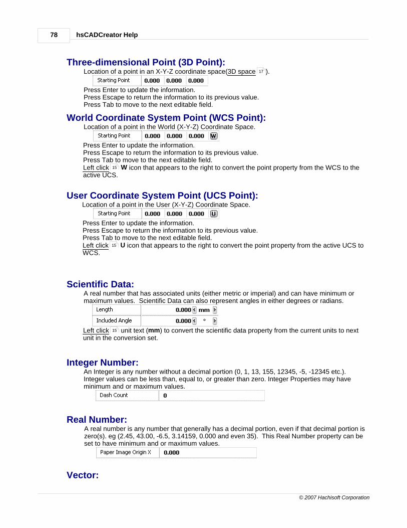
hsCADCreator Help78
© 2007 Hachisoft Corporation
Three-dimensional Point (3D Point):Location of a point in an X-Y-Z coordinate space(3D space ).
Press Enter to update the information.Press Escape to return the information to its previous value.Press Tab to move to the next editable field.
World Coordinate System Point (WCS Point):Location of a point in the World (X-Y-Z) Coordinate Space.
Press Enter to update the information.Press Escape to return the information to its previous value.Press Tab to move to the next editable field.Left click W icon that appears to the right to convert the point property from the WCS to theactive UCS.
User Coordinate System Point (UCS Point):Location of a point in the User (X-Y-Z) Coordinate Space.
Press Enter to update the information.Press Escape to return the information to its previous value.Press Tab to move to the next editable field.Left click U icon that appears to the right to convert the point property from the active UCS toWCS.
Scientific Data:A real number that has associated units (either metric or imperial) and can have minimum ormaximum values. Scientific Data can also represent angles in either degrees or radians.
Left click unit text (mm) to convert the scientific data property from the current units to nextunit in the conversion set.
Integer Number:An Integer is any number without a decimal portion (0, 1, 13, 155, 12345, -5, -12345 etc.).Integer values can be less than, equal to, or greater than zero. Integer Properties may haveminimum and or maximum values.
Real Number:A real number is any number that generally has a decimal portion, even if that decimal portion iszero(s). eg (2.45, 43.00, -6.5, 3.14159, 0.000 and even 35). This Real Number property can beset to have minimum and or maximum values.
Vector:
17
15
15
15

Handbook 79
© 2007 Hachisoft Corporation
An object defining direction and length of a ray.
Press Enter to update the information.Press Escape to return the information to its previous value.Press Tab to move to the next editable field.
Boolean (On/Off):Check box specifying True/False or On/Off or Yes/No Value.
Left click on the check box to change the value.
Multiple option:
These properties are also known as drop-down list. They are accessed by left clicking on thedown arrow and then selecting required option from list using left click .
File Selection:A File Selection property allows the user to select a file from the common file dialog by pressingthe ( ... ) button. The current or new selection will show up in the first portion of the property.
Text Field:A Text Field property is for adding common text to a property. Simply give the property focus byclicking on it and type in the text desired.
See also:Selection Property TreeTool Property TreeSnap Property TreeDrawing Property TreeViewport Property Tree
2.1.8 Property Trees
Property Tree is collection of properties arranged in a tree fashion. Each property in theproperty tree has associated brief description. A property in a property tree is selected by left clicking
on property name. Whenever a property is selected, its brief description is shown at the bottom ofthe property tree and the selected property name is highlighted. A property tree may have one ormore sub-trees within it. Each of these trees can be expanded/collapsed by double-clicking on thesub-tree name or the (+) or (-) icon in front of the sub-tree name.
15
15
15
259
260
261
262
263
77 77
15
16

hsCADCreator Help80
© 2007 Hachisoft Corporation
For more information on Property Trees used in hsCADCreator, please see chapter onhsCADCreator Property Trees .
See also:hsCADCreator Property Trees
2.1.9 Tools
This application is built on the concept of tools. Loosely speaking, a tool for hsCADCreator is animplementation with the ability to perform a certain class of operation or procedure with regards toviewing and editing a drawing.
Tool PropertiesEach tool may have a set of properties associated with it.
Tool Modes :Each tool may have one or more modes to work with. These modes are accessible fromthe Tool Properties window. For example, Clone Tool has more than one modes and they can be changed by selecting modefrom drop-down list.
Active ToolOnly one tool may be active at a time. By choosing a tool with a toolbar, menu, or shortcut key, you aremaking it the active tool. In the case of Stackable Tools, only the "top most" tool is active. The ToolPropertiesshows properties and options available for the active tool.
Stackable Tools and Tool Stack In hsCADCreator some tools work in conjunction with each other and they are known as stackabletools. When more than one tools are active it creates a tool stack. In a tool stack only the topmosttool is active at a time. When the topmost tool is deactivated it is removed from tool stack and the"new" topmost tool becomes active and ready for use.For example, 1. If you activate the Line Tool to create a line, and then hold down the mouse wheel while moving the
mouse, you will make the screen (and line) pan or move. Releasing the mouse wheel will cease the
258
258
159
260

Handbook 81
© 2007 Hachisoft Corporation
movement and other lines can now be created without having to select the Line Tool again.
2. If there is no entity selected when activating Clone Tool , both the Selection Tool and CloneTool will highlight until the selection of the entity is made. After the selection is done, the SelectionTool will be deactivated and only the Clone Tool will continue to be highlighted until the clone tool isfinished or another tool becomes active.
2.1.10 Toolbars
Toolbar
Toolbar is a collection of Tools . Tool buttons are grouped by their functionality into tool"bars". Similar tools are combined together in a toolbar for their easy placement and access.All of the toolbars have the ability to dock(be placed on the various edges of the drawingwindow) or place them anywhere on drawing screen. A toolbar can be moved by one offollowing methods depending on position of the toolbar:
1. Left mouse dragging from its anchor line.
2. Left mouse dragging from its title bar.
When a toolbar is moved near the edge of the hsCADCreator screen area, its title bar isremoved and the toolbar tightly fits on the edge to save the screen space. Once you havemanaged to position the toolbars and tool windows to fit your needs you can manage theirpositions by using the following commands. Visit Workspace Layout for moreinformation on managing the layouts.
Save Layout (Saves the current placement and sizes of all user interfaceelements within the workspace)Revert Layout (Returns the current placement and sizes of all user interfaceelements to the last Save Layout state)Save As... Layout (Saves a layout file to a user defined location)Load From... Layout (Loads a layout file from a user defined location)
Each toolbar in hsCADCreator can be customized weather that be size, location, toolslocated on the bar, or visibility. To learn more about the modifications you can make tothe toolbars visit the Customizing Toolbars chapter.
Flyout ToolbarMany toolbars have one or more than one toolbars hidden within them. These are known as Flyout Toolbars. Flyout Toolbars are provided to save the screen space and allow easyaccess to different Tool Modes . Flyout Toolbars are sub-toolbars hidden withinthe normaltoolbars and are designated by a small black arrow in the lower right hand corner of a toolbar
icon ( ). By simply pointing at the icon with the mouse cursor and right clicking , thishidden submenu will appear. The user may now choose a tool from the sub toolbar by left
159 101
80
16
16
279
279
279
279
279
279
275
80
15

hsCADCreator Help82
© 2007 Hachisoft Corporation
clicking . When a user selects a tool from the Flyout toolbar the selected tool will take theplace of the tool in the parent menu.
1. Activate the Flyout Toolbar:
Left Click on the ( ) down arrow located to the right of the icon. Thiswill activate the flyout toolbar.
2. Choosing New Tool to Activate:From the flyout toolbar select the tool you wish to use by left clicking on it.
3. Chosen Tool Replaces Old Tool in Parent Toolbar:After selection of the new tool notice that the chosen tool icon replaces the old
icon in the parent toolbar.
Following Flyout Toolbars are present in hsCADCreator: Entity Toolbar :
Arc Tools (4 additional tool choices available)Dimension Tools (6 additional tool choices available)
View Toolbar:
Rotate View Tools (10 additional tool choices available) Draw Plane/UCS Toolbar:
Preset UCS Snap Tools (6 additional tool choices available) Rotate Draw Plane Tools (4 additional tool choices available)Translate Draw Plane Tools (4 additional tool choices available)Clone Tools (4 additional tool choices available)
15
15
15
251
113
123
253
179
254
195
198
205
159

Handbook 83
© 2007 Hachisoft Corporation
See also:hsCADCreator Toolbars
2.1.11 Docking Window
Floating (UnDocked)
Docking windows have two major modes, Docked and UnDocked. The UnDocked mode iscommonly referred to as Floating. A Floating window can be positioned anywhere on thescreen where it will float above the various user interface elements. The image below showsthe Notification Window in Floating mode.
Docked
Another way to position windows is to Dock them to various other user elements. Forinstance the Notification Window below has been Docked to the bottom of the Drawingspace. When docked the window maintains a close relationship with the edges such thatspace is well managed.
250
267
267

hsCADCreator Help84
© 2007 Hachisoft Corporation
Dockable Windows Include:Notification WindowLayer WindowLibrary WindowHelp WindowSelection Properties WindowTool Properties WindowDrawing Properties WindowViewport Properties WindowSnaps Window
Docking toolbars also have two visibility modes while Docked. They are Pinned andUnPinned.
Pinned Docking Window
In the upper right hand corner of a Docking Window is a small Pin Icon. When aDocking window is docked this icon becomes visible. When the pin icon looks like
this ( ) the Docking Window is in the Pinned mode. This means that the windowwill be constantly visible and in the position that is seen. The image below shows the Notification Window Docked and Pinned to the bottom of the drawing space.
267
281
282
285
259
260
71
267
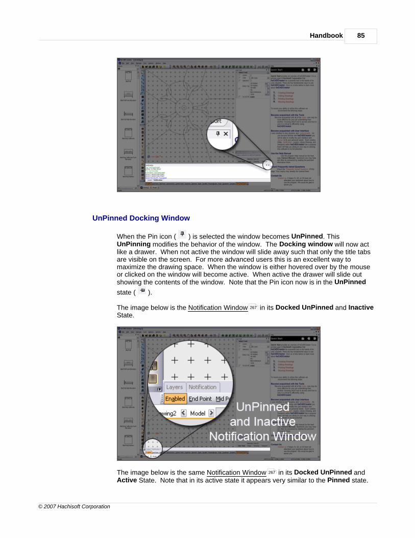
Handbook 85
© 2007 Hachisoft Corporation
UnPinned Docking Window
When the Pin icon ( ) is selected the window becomes UnPinned. ThisUnPinning modifies the behavior of the window. The Docking window will now actlike a drawer. When not active the window will slide away such that only the title tabsare visible on the screen. For more advanced users this is an excellent way tomaximize the drawing space. When the window is either hovered over by the mouseor clicked on the window will become active. When active the drawer will slide outshowing the contents of the window. Note that the Pin icon now is in the UnPinned
state ( ).
The image below is the Notification Window in its Docked UnPinned and InactiveState.
The image below is the same Notification Window in its Docked UnPinned andActive State. Note that in its active state it appears very similar to the Pinned state.
267
267

hsCADCreator Help86
© 2007 Hachisoft Corporation
2.1.11.1 Docking Procedure
Docking Window Management
1. To Dock a window the window must be in Pinned or Floating mode.
2. Select and hold the left mouse button down on the Title Bar of the windowyou want to dock.
3. Utilize the Docking aids to place the window in the desired location.
Drag the Docking toolbar over the desired docking aid ( ) and release to position. Theimages below depict the docking aids and the approximate resulting placement.
Main Window Docking Aids
83 83

Handbook 87
© 2007 Hachisoft Corporation
Along with the above Main Window Docking aids there are Current Window Docking aidsthat will allow placement with relation to the window that is under the cursor. The image belowdepicts the docking aids approximate resulting placement if we were hovering over theSelection window.

hsCADCreator Help88
© 2007 Hachisoft Corporation
The Docking aid ( ) is used for placing the docking window with relation to thewindow under the cursor.
The center of the docking aid above is also a Docking aid ( ). This will place the dockingwindow as a tab within the window that is under the cursor. If that window is not a collection oftabs then this option will not be available.
See Also:Workspace LayoutCustomizing Toolbars
2.1.12 Dialogs
Dialog is a collection of various user interface elements (tools , property trees , and properties). Dialogs provides easy access and management of more complex objects and entities. Dialogs
also provides easy way to do complex tasks. Most of dialogs when activated restricts access to the hsCADCreator main screen and other user interfaces outside the dialog. For more information on
dialogs used in hsCADCreator, please see chapter on hsCADCreator Dialogs .
279
275
80 79
77
264

Handbook 89
© 2007 Hachisoft Corporation
See also:hsCADCreator Dialogs
2.1.13 Undo/Redo
To Undo a recently made change in drawing:Using the keyboard
: Press Ctrl+Z from the keyboard. Repeat as necessary to undo additional changes inreverse order.
Using the Mouse:
: Go to the Edit menu and select ÄUndo or
: Go to the File Toolbar and select the icon button
To Redo a recently undone change in drawing: Using the keyboard:
: Press Ctrl +Y from the keyboard. Repeat as necessary to redo additional undonechanges in reverse order.
Using the mouse:
: Go to the Edit menu and select ÄRedo
264
94
256
94

hsCADCreator Help90
© 2007 Hachisoft Corporation
or
: Go to the File Toolbar and select the icon button
2.2 User Interface
The User Interface of hsCADCreator is designed to be a simple, yet powerful tool for dealing withdaily tasks in computer aided drafting and design. The following types of user interfaces are available
in hsCADCreator.
· Menus
· Tools
· Toolbars
· Property Trees
· Dialogs
· Notify Window
· Status Bar
· Visual Aids
· Keyboard Shortcuts
· Customizing Toolbars
· Workspace Layout
· Layer Window
· Library Window
· Help Window
2.2.1 hsCADCreator Menus
There are eight main Menus available in hsCADCreator. They are located above the drawingscreen in the upper left hand corner of the monitor screen.
Main Menu:
1. File Menu 2. Edit Menu 3. View Menu
256
90
100
250
258
264
267
269
270
271
275
279
281
282
285
93
94
94

Handbook 91
© 2007 Hachisoft Corporation
4. Manage Menu 5. Tools Menu 6. Options Menu 7. Window Menu 8. Help Menu
Context Menus:
In addition, there are also context menus available. Depending upon the tool in which the user is
working, these are accessed by 8right clicking the mouse or pressing the 7Shift key on the
keyboard while 8right clicking the mouse.
1. View Options menu (available to most tools) Access by 8right clicking the mouse with thecursor in the drawing screen. Options available:
· Pan· Rotate View· Zoom
· Zoom In· Zoom Out· Zoom Extents· Zoom Window
2. Planar Polyline Tool menu (available to the Planar Polyline Tool only) Access by 8rightclicking the mouse with the cursor in the drawing screen. Options available:
· Line Mode· Bulge Mode· Toggle Closed· End Polyline
3. 3D Polyline Tool menu (available to the 3D Polyline Tool only) Access by 8right clicking themouse with the cursor in the drawing screen. Options available:
96
97
99
99
100
100
15
15
15
178
183
176
177
178
175
110
15
110
110
110
110
15

hsCADCreator Help92
© 2007 Hachisoft Corporation
· End Polyline· Toggle Closed
4. Temporary Snaps menu (available most tools) Access by holding 7Shift + 8right clickingwith the cursor in the drawing screen. The Temporary Snaps act much like the Permanent EntitySnaps except that they last for only one mouse click. You can temporarily disable/enable thecurrently set Entity Snaps and or Grid Snaps . You may also select one or more Entity Snaps
you desire to use temporarily. This is useful for entity snapping that you do not commonly use butwant to quickly switch too. Options available:
· Entity Snaps· Grid Snaps· End Point· Mid Point· Intersection· Center Point· Quadrant· Insertion· Nearest· Node· Perpendicular· Polar· Tangent· Parallel· Set Permanent Snaps ( This will translate your Temporary Snap choices into your
permanent Entity Snaps .)
112
112
15
72
72 74
72
72
74
72
72
72
72
72
72
72
72
72
72
72
72
72

Handbook 93
© 2007 Hachisoft Corporation
2.2.1.1 File Menu
The File Menu in hsCADCreator has the following options available:
1. New (Start a new drawing) 2. Open... (access a named drawing file previously saved) 3. Save (store a drawing for future access) 4. Save As...(store a drawing under a different file name)
5. Import... (.dwf file format) 6. Export... (save a copy of the drawing under a different file format) 7. Close (terminate the current drawing file) 8. Print / Plot (print a drawing file) 9. Print / Plot Preview (see beforehand how a drawing file will be printed) 10. Recent Files (displays files you have recently opened for quick access) 11. Exit (terminate all documents as well as the program)
(Note: Each option above is equipped with a keyboard shortcut to improve drawing efficiency; tocustomize your shortcuts, see Key Accelerators under Options Menu )
14
14
271 99

hsCADCreator Help94
© 2007 Hachisoft Corporation
2.2.1.2 Edit Menu
The Edit Menu in hsCADCreator has the following options available:
1. Undo (take back the most recent change made within the drawing) 2. Redo (restore a change that has been removed using the Undo command) 3. Select All (selection of every entity) 4. Copy (duplicate one or more entities) 5. Paste (transfer selected entity to new location; used in conjunction with Copy above or Cut
below) 6. Paste as block (transfer selected entities as a block to a new location) 7. Cut (remove selected entity; used in conjunction with Paste or Paste as block above)
(Note: Each option above is equipped with a keyboard shortcut to improve drawing efficiency; tocustomize your shortcuts, see Key Accelerators under Options Menu )
2.2.1.3 View Menu
The View Menu in hsCADCreator has the following options available:
89
89
61
271 99

Handbook 95
© 2007 Hachisoft Corporation
1. Grid (Toggles the framework of evenly spaced/parallel vertical and horizontal lines used as adrawing reference on/off)
2. Grid Snap (Toggles the grid snap ability on/off) 3. Entity Snaps (Sub-menu)
a. Enabled (Enable/Disable Permanent Entity Snaps )b. End Point (Snap to an end point of a line segment)c. Mid Point (Snap to mid point of a line segment)d. Intersection (Snap to the intersection point)e. Center Point (Snap to center of a circle , ellipse or arc )f. Insertion (Snap to the Insertion point of blocks , images , or text )g. Nearest (Snap to the nearest point on the entity to the cursor)h. Node (Snaps to the point entity only)i. Parallel (Snap parallel to nearest line to cursor)j. Perpendicular (Snap to perpendicular point on line segment)k. Polar (Snap to 0, 45deg, 90deg... etc)l. Quadrant (Snap to the nearest quadrant on a circle , ellipse or arc )m. Tangent (Snap to the point tangent to the circle , ellipse or arc )
4. Toolbar (Sub-menu)
a. File Toolbar (Show/Hide this toolbar)b. Create Toolbar (Show/Hide this toolbar)c. Modify Toolbar (Show/Hide this toolbar)d. View Toolbar (Show/Hide this toolbar)e. Draw Plane/UCS Toolbar (Show/Hide this toolbar)f. Render Toolbar (Show/Hide this toolbar)g. Library Toolbar (Show/Hide this toolbar)e. Measure Toolbar (Show/Hide this toolbar)
5. Property Bar (Prop tree Tool Properties to the right of the drawing screen when a tool isactivated)
6. Status Bar (program information bar found at the bottom of drawing screen) 7. Regen (redraw all entities with updated information)
(Note: Each option above is equipped with a keyboard shortcut to improve drawing efficiency; tocustomize your shortcuts, see Key Accelerators under Options Menu )
Also See:Toolbars
75
74 74
72
72 72
72
72
72
72 30 32 28
72 61 47 43
72
72 22
72
72
72
72 30 32 28
72 30 32 28
250
256
103
253
253
193
256
257
257
258
269
217
271 99
250

hsCADCreator Help96
© 2007 Hachisoft Corporation
2.2.1.4 Manage Menu
The Manage Menu in hsCADCreator has the following options available:
1. Entire Library... (access to all aspects manageable in a single screen--the following beloware separate screens for each aspect)
2. Blocks... (entity/grouping of entities that can be placed in a drawing) 3. Colors... (for background, lines, entities, gradients, etc.) 4. Dimension Styles (add, remove, modify dimension styles)
5. Drawing Layouts... (model, paperspace, etc. and Layout) 6. External References... (attach, detach, load/reload, unload, and bind embedded drawings
within a drawing) 7. Hatch Styles... (add, remove, and import patterns/gradients) 8. Image Definitions... (picture(s) that can be placed in a drawing) 9. Layers... (set color, line weight, line style, visibility, printed or not, etc.) 10. Line Types... (add, remove and import linestyles)
11. Modelspace Viewports... (change properties)
217
218
220
221
232
223
224
228
230
233
242
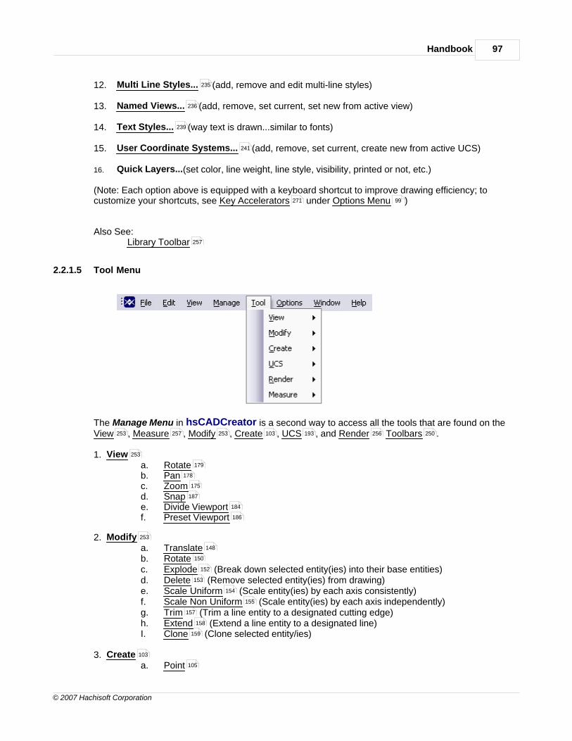
Handbook 97
© 2007 Hachisoft Corporation
12. Multi Line Styles... (add, remove and edit multi-line styles) 13. Named Views... (add, remove, set current, set new from active view) 14. Text Styles... (way text is drawn...similar to fonts) 15. User Coordinate Systems... (add, remove, set current, create new from active UCS)
16. Quick Layers...(set color, line weight, line style, visibility, printed or not, etc.)
(Note: Each option above is equipped with a keyboard shortcut to improve drawing efficiency; tocustomize your shortcuts, see Key Accelerators under Options Menu )
Also See:Library Toolbar
2.2.1.5 Tool Menu
The Manage Menu in hsCADCreator is a second way to access all the tools that are found on theView , Measure , Modify , Create , UCS , and Render Toolbars .
1. View a. Rotateb. Panc. Zoomd. Snape. Divide Viewportf. Preset Viewport
2. Modifya. Translateb. Rotate c. Explode (Break down selected entity(ies) into their base entities)d. Delete (Remove selected entity(ies) from drawing)e. Scale Uniform (Scale entity(ies) by each axis consistently)f. Scale Non Uniform (Scale entity(ies) by each axis independently)g. Trim (Trim a line entity to a designated cutting edge)h. Extend (Extend a line entity to a designated line)I. Clone (Clone selected entity/ies)
3. Createa. Point
235
236
239
241
271 99
257
253 257 253 103 193 256 250
253
179
178
175
187
184
186
253
148
150
152
153
154
155
157
158
159
103
105

hsCADCreator Help98
© 2007 Hachisoft Corporation
b. Linec. Multi Lined. Polyline3. Arcf. Circleg. Ellipseh. Dimension Indicatori. Textj. Blockk. Block Insertionl. Image Insertionm. Hatchn. Viewport (Only active while in a paperspace)o. Poly Face Mesh
4. UCSa. Rotateb. Translatec. Snapd. Align UCS to Viewe. Align View to UCSf. UCS Origin to WCS origing. Align UCS Axis to WCS Axish. Select USC Via Entity(ies)
5. Rendera. 2D Wireframeb. 3D Wireframec. Hiddene. Flat Shadedf. Gouraud Shadedg. Flat Shaded w/Edgesh. Gouraud Shaded w/Edges
6. Measurea. Measure Distanceb. Measure Areac. Measure Angle
(Note: Many of the above options and sub menus are equipped with a keyboard shortcut to improvedrawing efficiency; to customize your shortcuts, see Key Accelerators under Options Menu )
Also See:View ToolbarModify ToolbarCreate ToolbarDraw Plane/UCS ToolbarRender ToolbarMeasure ToolbarKeyboard Shortcuts
106
108
110
113
120
121
123
136
140
142
144
138
146
139
254
198
205
195
210
211
211
212
212
256
213
214
214
214
215
216
216
257
245
247
249
271 99
253
253
103
193
256
257
271
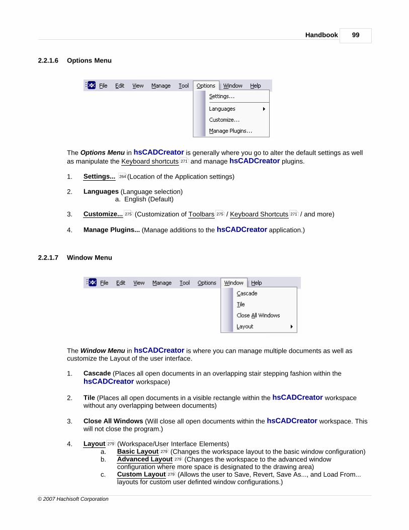
Handbook 99
© 2007 Hachisoft Corporation
2.2.1.6 Options Menu
The Options Menu in hsCADCreator is generally where you go to alter the default settings as well
as manipulate the Keyboard shortcuts and manage hsCADCreator plugins.
1. Settings... (Location of the Application settings)
2. Languages (Language selection)a. English (Default)
3. Customize... (Customization of Toolbars / Keyboard Shortcuts / and more)
4. Manage Plugins... (Manage additions to the hsCADCreator application.)
2.2.1.7 Window Menu
The Window Menu in hsCADCreator is where you can manage multiple documents as well ascustomize the Layout of the user interface.
1. Cascade (Places all open documents in an overlapping stair stepping fashion within thehsCADCreator workspace)
2. Tile (Places all open documents in a visible rectangle within the hsCADCreator workspacewithout any overlapping between documents)
3. Close All Windows (Will close all open documents within the hsCADCreator workspace. Thiswill not close the program.)
4. Layout (Workspace/User Interface Elements)a. Basic Layout (Changes the workspace layout to the basic window configuration)b. Advanced Layout (Changes the workspace to the advanced window
configuration where more space is designated to the drawing area)c. Custom Layout (Allows the user to Save, Revert, Save As..., and Load From...
layouts for custom user definted window configurations.)
271
264
275 275 271
279
279
279
279

hsCADCreator Help100
© 2007 Hachisoft Corporation
5. Current Open Drawings (List of open drawings within the workspace. Selection will activatethat document and make it the current working document.)
Also See:Toolbars
2.2.1.8 Help Menu
The Help Menu in hsCADCreator provides an easy way to open the help documentation, managethe license and discover the current program version you are working with.
1. About hsCADCreator... (Displays the About dialog that will display the program versionnumber and quick view at the license status.)
2. Tutorials (This is a link to helpful tutorials on Hachisoft Corporation's website)
3. www.hachisoft.com (This is a link to the designers of hsCADCreator. Check this site forupdate, version upgrades and plugins.)
4. Check for Updates (This will link you to the hsCADCreator product site to ensure you havethe latest version of the software.4. Support (Convenient ways to request support or a new feature to Hachisoft Corporation)4. Purchase Upgrade to Full Version (This is a web link to the online store where you can
purchase one or more licenses of hsCADCreator.) 5. Remove License ( Ability to remove a license from a computer for use on a differentcomputer)5. Activate License (Opens the License management dialog) 6. Help (Activates this help documentation)
2.2.2 hsCADCreator Tools
This application is built on the concept of tools. Loosely speaking, a tool for hsCADCreator is animplementation of ability to perform a certain class of operation or procedure with regards to viewingand editing a drawing. All tool gives different type of notifications in notification window as youadvance to different steps.
250
296 313
264
300
296
267

Handbook 101
© 2007 Hachisoft Corporation
Tool Modes· Select, click and drag mouse-based mode· Context-sensitive tool properties allow for a precise data-entry mode
Tool PropertiesEach tool may have a set of properties associated with it. Tool properties can be changed to changethe tool's behavior.
hsCADCreator has always one active tool at any time. There may be more than one tools onTool Stack but only one tool is active at any given time.
hsCADCreator has six different tool categories available to the user in addition to the standard filetools:
1 Create Tools : Tools used to draw an entity
2 Modify Tools : Tools used to change an existing entity in the drawing.
3 View Tools : Tools used to alter viewing parameters (i.e. camera location, cameraangle, camera zoom level, etc.)
4 Draw Plane(UCS) Tools : Tools used to create/edit User coordinate system.
5. Rendering Tools : Tools used to produce the different rendering view of the drawing.
6. Library Tools : Tools used to add, remove, or modify specialized object types
7. Measure Tools : Tools to measure lengths and area
2.2.2.1 Selection Tool
Entity toolbar :
The Selection Tool is used to choose/select created entities for modification/deletion. After selection,an entity can be modified by utilizing the Modify Toolbar , changing the entity properties , or bychanging its grip points .
Making a Selection:
Find the Selection Tool icon from the Entity Toolbar (color coded blue) highlight it.Click on highlighted tool and it will become the active tool ready to perform a selection.Move the mouse close to the entity.
There are three methods to select any entity/entities:Click : Simply click on entity to select it. This is selection
by a single selection point.
Fully enclosed : Drag left mouse button over the entities from topleft side of entities towards bottom right side ofentities and release mouse . A temporary rectanglewith a solid line be displayed. Any entities fullyenclosed in the drawn rectangle will be selected.
80
80
103
147
173
193
213
217
244
251
253 77
74
251
15
15
16
16

hsCADCreator Help102
© 2007 Hachisoft Corporation
Partially enclosed : Drag left mouse button over the entities frombottom right side of entities towards top left side ofentities and release mouse . A temporaryrectangular box will be drawn with a dashed border.Any entities that are crossing or fully enclosed in thedrawn rectangle boundary will be selected.
Selection Options:
There are multiple options within hsCADCreator to enable a more specific selection set.Selections can be made based on Layer , Color , Entity Type , and UCS relativity.Below are the selection tool properties and their options.
To make a specific selection. Select the options from the Selection Options property tree.Then perform the selection the same way as Making a Selection section above
Property Name Data Type Description
Layers Multi-option selection boxSelection of Entity(ies) onchosen Layer(s)
Color Multi-option selection boxSelection of Entity(ies) withchosen Color(s)
Selection Size Integer NumberMaximum Size of SelectionSet
Entity Type Multi-option selection boxSelection of Entity(ies) ofchosen Type(s)
On UCS Plane Real NumberSelection of Entity(ies) withina tolerance of current UCSPlane
16
16
64 51 21 17
79
79
78
79
78

Handbook 103
© 2007 Hachisoft Corporation
Tool Options:
Escape (Esc): key clears the current selection set.
Space: key Resets this tool.
2.2.2.2 Create Tools
hsCADCreator has twenty-two different tools available to create drawing entities. The Create Toolscan be accessed by using the blue colored Entity Toolbar , or by accessing the Create option fromthe Tool Menu . The Create tools primary function is to allow the creation of drawing entitiesthrough a user friendly process of steps.
1. Selection Tool Facilitates the selection of entities.
2. Point Tool Facilitates the creation of a Point Entity
3. Line Tool Facilitates the creation of a Line Entity
4. Multi Line Tool Facilitates the creation of a Multi Line Entity
5. Planar Polyline Tool Facilitates the creation of a planar polyline.
6. 3D Polyline Tool Facilitates the creation of a polyline within 3D Space
7. Arc Tools Facilitates the creation of Arc Entities
Start-Middle-End Arc Tool Facilitates the creation of an Arc Entity using Start,Middle and End points.
Start-Center-End Arc Tool Facilitates the creation of an Arc Entity using Start,Center and End points.
Start-Center-Angle Arc Tool Facilitates the creation of an Arc Entity using Start
251
97
101
105
106
108
110
112
113
114
115
117

hsCADCreator Help104
© 2007 Hachisoft Corporation
and Center points and an Angle.
Start-Center-Chord Length Arc Tool Facilitates the creation of an Arc Entityusing Start and Center points and a Chord length.
8. Circle Tool Facilitates the creation of a Circle Entity
9. Ellipse Tool Facilitates the creation of an Ellipse Entity
10. Dimension Tools Facilitates the creation of Dimension Entities
Aligned Dimension Tool Facilitates the creation of a Dimension Entity that alignsto two user directed points.
Linear Dimension Tool Facilitates the creation of a Dimension Entity that depictsthe linear distance between to user defined points.
Ordinate Dimension Tool Facilitates the creation of a Dimension Entity thatdisplays either the X or Y distance from the user specified origin
Radial Dimension Tool Facilitates the creation of a Dimension Entity that depictsthe radius of an entity.
Diametric Dimension Tool Facilitates the creation of a Dimension Entity thatdepicts the diameter of an entity.
Angular Dimension Tool Facilitates the creation of a Dimension Entity depictingan angle specified from the user supplied center, start and end points.
11. Text Tool Facilitates the creation of a Text Entity.
12. Hatch Tool Facilitates the creation of a Hatch Entity within a specified area.
13. Face Mesh Tool Facilitates the creation of a Face Entity on the current UCS Drawplane.
14. Block Definition Tool Facilitates the creation of a Block Definition or group of entitiescombined together to create a single entity.
15. Block Insertion Tool Facilitates the creation and placement of a Block Entity from apreviously created Block Definition.
16. Image Insertion Tool Facilitates the creation of an Image Entity.
17. Viewport Creation Tool Facilitates the creation of a Viewport Entity (Used in Layoutsonly)
119
120
121
123
124
126
128
130
132
134
136
138
139
140
142
144
146

Handbook 105
© 2007 Hachisoft Corporation
2.2.2.2.1 Point Tool
Entity toolbar :
The Point Tool is responsible for creating Point Entities .
Creating a Point:Activate the Point Tool:
Find the Point Tool icon from the Entity Toolbar (color coded blue) andhighlight it. While highlighted Click on the tool. The tool is now the active tool andready for use.
Creating a Point using the Mouse:1. Click anywhere on the drawing screen to create a Point Entity at thatlocation.
Reset:You have just added a Point Entity to the drawing at the designated location. Thetool has now Reset and you can either continue with other tools or add in anotherpoint. Using Reset at any time while using this tool cancels all previous steps andrestarts the tool.
Creating a Point using the Property Tree: To add a Point Entity from user supplied data do the following. Move the mousecursor beyond the right side of the drawing screen to the Tool Property Tree .
1. To add a Point alter the numerical values for X, Y, and Z. on the 3D PointProperty Item Point and press Enter to accept.
Reset:You have just added a Point Entity to the drawing at the designated location. Thetool has now Reset and you can either continue with other tools or add in anotherpoint. Using Reset at any time while using this tool cancels all previous steps andrestarts the tool.
Tool Options:
251
22
251
15
15 22
22
22
260
77
22

hsCADCreator Help106
© 2007 Hachisoft Corporation
Escape (Esc): key cancels current tool and activates the default tool (Selection Tool).
Space: key Resets this tool.
Also See:Point EntityGridGrid SnapsEntity SnapsNotification Bar
2.2.2.2.2 Line Tool
Entity toolbar :
The Point Tool is responsible for creating Line Entities .
Creating a Line:Activate the Line Tool:
Find the Line Tool icon from the Entity Toolbar (color coded blue) andhighlight it. While highlighted Click on the tool. The tool is now the active tool andready for use.
Creating a Line using the Mouse:1. Click anywhere on the drawing screen to designate the Start Point at that
location.2. Click anywhere on the drawing screen to designate the End Point at that
location. 3. If in Specify Length Mode move the mouse to the designated length of the
Line Entity and click . (The length must be greater than zero and the newsegment will always be created along the two specified points.)
4. A Line Entity has been added. If in Contiguous Mode the tool will notReset. The End Point of the newly created Line Entity will automaticallybecome the Start Point for a new Line Entity and you will repeat steps 2,3and 4 until finished with the tool.
Reset:You have just added a Line Entity to the drawing at the designated location. Thetool has now Reset and you can either continue with other tools or add in anotherLine Entity . Using Reset at any time while using this tool cancels all previoussteps and restarts the tool.
Creating a Line using the Property Tree: To add a Line Entity from user supplied data do the following. Move the mousecursor beyond the right side of the drawing screen to the Tool Property Tree .
101
22
75
74
72
267
251
23
251
15
15
15
23 15
23
23
23
23
23
23
260

Handbook 107
© 2007 Hachisoft Corporation
1. Type in the Start Point point data into the "Start Point" 3D Point Property Field found on the Tool Property Tree and press Enter to accept.
2. Type in the End Point point data into the "End Point" 3D Point Property Field found on the Tool Property Tree and press Enter to accept.
3. If in Specify Length Mode type in the Length data into the "Length" ScientificData Field found on the Tool Property Tree and press Enter to accept.
4. A Line Entity has been added. If in Contiguous Mode the tool will notReset. The End Point of the newly created Line Entity will automaticallybecome the Start Point for a new Line Entity and you will repeat steps 2,3and 4 until finished with the tool.
Reset:You have just added a Line Entity to the drawing at the designated location. Thetool has now Reset and you can start adding another Line Entity if desired. UsingReset at any time while using this tool cancels all previous steps and restarts the tool.
Tool Options:Contiguous Mode: allows the user to create multiple Line Entities that simulate apolyline's connectivity. Specify Length: allows the user to specify the Length of the line segment as part of theLine Entity creation process.
Escape (Esc): key cancels current tool and activates the default tool (Selection Tool).
Space: key Resets this tool.
Also See:Line EntityGridGrid SnapsEntity SnapsNotification Bar
77 260
77 260
77 260
23
23
23
23
23
23
23
101
23
75
74
72
267

hsCADCreator Help108
© 2007 Hachisoft Corporation
2.2.2.2.3 Multi Line Tool
Entity toolbar :
The Mulit Line Tool is responsible for creating Multi Line Entities .
Creating a Multi Line:Activate the Multi Line Tool:
Find the Mulit Line Tool icon from the Entity Toolbar (color coded blue) andhighlight it. While highlighted Click on the tool. The tool is now the active tool andready for use.
Creating a Multi Line using the Mouse:1. Click anywhere on the drawing screen to designate the Start Point at that
location.2. Click anywhere on the drawing screen to designate the End Point at that
location. 3. If in Specify Length Mode move the mouse to the designated length of the
Multi Line Entity and click . (The length must be greater than zero and thenew segment will always be created along the two specified points.)
4. A Line Entity has been added. If in Contiguous Mode the tool will notReset. The End Point of the newly created Multi Line Entity willautomatically become the Start Point for a new Multi Line Entity and you willrepeat steps 2,3 and 4 until finished with the tool.
Reset:You have just added a Multi Line Entity to the drawing at the designated location.The tool has now Reset and you can either continue with other tools or add inanother Multi Line Entity . Using Reset at any time while using this tool cancels allprevious steps and restarts the tool.
Creating a Multi Line using the Property Tree: To add a Multi Line Entity from user supplied data do the following. Move themouse cursor beyond the right side of the drawing screen to the Tool Property Tree
.
251
24
251
15
15
15
24 15
23
24
24
24
24
24
260

Handbook 109
© 2007 Hachisoft Corporation
1. Type in the Start Point point data into the "Start Point" 3D Point Property Field found on the Tool Property Tree and press Enter to accept.
2. Type in the End Point point data into the "End Point" 3D Point Property Field found on the Tool Property Tree and press Enter to accept.
3. If in Specify Length Mode type in the Length data into the "Length" ScientificData Field found on the Tool Property Tree and press Enter to accept.
4. A Multi Line Entity has been added. If in Contiguous Mode the tool willnot Reset. The End Point of the newly created Multi Line Entity willautomatically become the Start Point for a new Multi Line Entity and youwill repeat steps 2,3 and 4 until finished with the tool.
Reset:You have just added a Multi Line Entity to the drawing at the designated location.The tool has now Reset and you can start adding another Multi Line Entity ifdesired. Using Reset at any time while using this tool cancels all previous steps andrestarts the tool.
Tool Options:Contiguous Mode: allows the user to create continuous Multi Line Entity .Specify Length: allows the user to specify the Length of the line segment as part of theMulti Line Entity creation process.
Escape (Esc): key cancels current tool and activates the default tool (Selection Tool).
Space: key Resets this tool.
Also See:Multi Line Entity
77 260
77 260
77 260
24
24
24
24
24
24
24
101
24

hsCADCreator Help110
© 2007 Hachisoft Corporation
GridGrid SnapsEntity SnapsNotification Bar
2.2.2.2.4 Planar Polyline Tool
Entity toolbar :
The Planar Polyline Tool is responsible for creating Planar Polyline Entities.
Creating a Planar Polyline:Activate the Planar Polyline Tool:
Find the Planar Polyline Tool icon from the Entity Toolbar (color coded blue)and highlight it. While highlighted Click on the tool. The tool is now the active tooland ready for use.
Creating a Planar Polyline using the Mouse:1. Click anywhere on the drawing screen to designate the first Current Point at
that location. This will add a Polyline vertex at this location and set the Previous Point to this value.
2. If there only one vertex currently associated with the Planar Polyline thenmove your mouse and click to add a second vertex, otherwise skip this step.
3. If in Specify Length Mode move the mouse until it displays the desired lengthof the Planar Polyline and then click .
4. Repeat Step 1, 2 ,and 3 until all desired vertices have been added.
5. Press Shift+Enter to finish and add the Planar Polyline to the drawing.
Reset:You have just added a Planar Polyline to the drawing with vertices at thedesignated locations. The tool has now Reset and you can either continue with othertools or add in another Planar Polyline . Using Reset at any time while using thistool cancels all previous steps and restarts the tool.
Creating a Planar Polyline using the Property Tree: To add a Planar Polyline from user supplied data do the following. Move themouse cursor beyond the right side of the drawing screen to the Tool Property Tree
.
75
74
72
267
251
26
251
15
15
26
15
26 15
26
26
26
26
260

Handbook 111
© 2007 Hachisoft Corporation
1. Type in the Current Point point data into the "Current Point" 3D PointProperty Field found on the Tool Property Tree and press Enter toaccept. This will add a Polyline vertex at this location and set the PreviousPoint to this value.
2. If only one vertex has been added type in the Current Point point data into the"Current Point" 3D Point Property Field found on the Tool Property Treeand press Enter to accept.
3. If in Specify Length Mode type in the Length data into the "Length" ScientificData Field found on the Tool Property Tree and press Enter to accept.
4. Repeat Step 1, 2 ,and 3 until all desired vertices have been added.
5. Press Shift+Enter to finish and add the polyline to the drawing.
Reset:You have just added a Planar Polyline to the drawing with vertices at thedesignated locations. The tool has now Reset and you can either continue with othertools or add in another Planar Polyline . Using Reset at any time while using thistool cancels all previous steps and restarts the tool.
Tool Options:
Tab: Draw Bulge Mode allows the user to draw arcs as a polyline segment.
Ctrl+Enter: Draw Closed Mode allows the user to create a Planar Polyline Entitythat will add a segment from the Last Point in the polyline back to the First Point in thepolyline. Specify Length Mode allows the user to specify the Length of a particular polylinesegment as part of the Planar Polyline creation process.
Right Click: Options allows the user to view a Planar Polyline Context Menu withoptions for use in creating the Planar Polyline Entities .
Shift+Enter: this keystroke will complete and add the polyline to the drawing.
Escape (Esc): key cancels current tool and activates the default tool (Selection Tool).
Space: key Resets this tool.
77 260
77 260
77 260
26
26
26
26
26
91
26
101

hsCADCreator Help112
© 2007 Hachisoft Corporation
Also See:Planar PolylineGridGrid SnapsEntity SnapsNotification Bar
2.2.2.2.5 3D Polyline Tool
Entity toolbar :
The 3D Polyline Tool is responsible for creating 3D Polyline Entities
Creating a 3D Polyline:Activate the 3D Polyline Tool:
Find the 3D Polyline Tool icon from the Entity Toolbar (color coded blue)and highlight it. While highlighted Click on the tool. The tool is now the active tooland ready for use.
Creating a 3D Polyline using the Mouse:1. Click anywhere on the drawing screen to designate the first Current Point at
that location. This will add a Polyline vertex at this location and set the Previous Point to this value.
2. Repeat Step 1 until all desired vertices have been added.
3. Press Shift+Enter to finish and add the 3D Polyline to the drawing.
Reset:You have just added a 3D Polyline to the drawing with vertices at the designatedlocations. The tool has now Reset and you can either continue with other tools oradd in another 3D Polyline . Using Reset at any time while using this tool cancelsall previous steps and restarts the tool.
Creating a 3D Polyline using the Property Tree: To add a 3D Polyline from user supplied data do the following. Move the mousecursor beyond the right side of the drawing screen to the Tool Property Tree .
26
75
74
72
267
251
27
251
15
15
27
27
27
27
260

Handbook 113
© 2007 Hachisoft Corporation
1. Type in the Current Point point data into the "Current Point" 3D PointProperty Field found on the Tool Property Tree and press Enter toaccept. This will add a Polyline vertex at this location and set the PreviousPoint to this value.
2. Repeat Step 1 until all desired vertices have been added.
3. Press Shift+Enter to finish and add the 3D Polyline to the drawing.
Reset:You have just added a 3D Polyline to the drawing with vertices at the designatedlocations. The tool has now Reset and you can either continue with other tools oradd in another 3D Polyline . Using Reset at any time while using this tool cancelsall previous steps and restarts the tool.
Tool Options:
Ctrl+Enter: Draw Closed Mode allows the user to create a 3D Polyline Entity thatwill add a polyline segment from the Last Point in the polyline back to the First Point inthe polyline.
Right Click: Options allows the user to view a 3D Polyline Context Menu withoptions for use in creating the 3D Polyline Entities .
Shift+Enter: this keystroke will complete and add the polyline to the drawing.
Escape (Esc): key cancels current tool and activates the default tool (Selection Tool).
Space: key Resets this tool.
Also See:3D PolylineGridGrid SnapsEntity SnapsNotification Bar
2.2.2.2.6 Arc Tools
Entity toolbar :
The Arc Tools are responsible for creating Arc Entities .
Creating an Arc:
Activate an Arc Tool:
Find one of the Arc Tool icons from the Entity Toolbar (colorcoded blue) and highlight it. While highlighted Click on the tool. The tool is nowthe active tool and ready for use. This set of tools is part of a Flyout toolbar .
Creating the Arc:There are four different method that can be used to create an Arc Entity.
77 260
27
27
27
27
91
27
101
27
75
74
72
267
251
28
251
15
81

hsCADCreator Help114
© 2007 Hachisoft Corporation
1. Start-Middle-End Arc Tool : (default) Arcs that pass through three chosenpoints ( a Start Point, Middle Point, and End Point)
2. Start-Center-End Arc Tool : Arcs drawn from a Start Point to an EndPoint based on the location of a (circle's) Center Point
3. Start-Center-Angle Arc Tool : Arcs drawn from a Start Point to a point ona circle with a specific included angle based on the location of the (circle's) CenterPoint
4. Start-Center-Chord Length Arc Tool : Arcs drawn from a Start Point to apoint of specified chord length based on the location of the (circle's) Center Point
Also See: Arc EntityFlyout Toolbar
2.2.2.2.6.1 Start-Middle-End Arc Tool
Entity toolbar :
The Arc Tools is responsible for creating Arc Entities .
Creating an Arc (Start-Middle-End):Activate the Arc (Start-Middle-End) Tool:
Find the Arc (Start-Middle-End) Tool icon from the Entity Toolbar (colorcoded blue) or Arc Flyout Toolbar and highlight it. While highlighted Click onthe tool. The tool is now the active tool and ready for use.
Creating an Arc (Start-Middle-End) using the Mouse:1. Click anywhere on the drawing screen to designate the Start Point of the
Arc at that location.2. Move the mouse and Click on a point you desire to be on the Arc but is not
the same as the Start Point. This is the Middle Point. 3. Move the mouse and Click on a point you wish to designate as the End
Point. This is the location at which the arc will no longer be drawn.
Reset:You have just added an Arc Entity to the drawing using a Start Point, Middle Point(point along the arc), and End Point. The tool has now Reset and you can eithercontinue with other tools or add in another Arc Entity . Using Reset at any timewhile using this tool cancels all previous steps and restarts the tool.
Creating an Arc (Start-Middle-End) using the Property Tree: To add an Arc Entity from user supplied data using the (Start-Middle-End) methoddo the following . Move the mouse cursor beyond the right side of the drawing screento the Tool Property Tree .
114
115
117
119
28
81
251
28
251
81 15
15
15
15
28
28
28
260

Handbook 115
© 2007 Hachisoft Corporation
1. Type in the Start Point point data into the "Start Point" 3D Point Property Field found on the Tool Property Tree and press Enter to accept. This will
position the starting point for the arc.2. Type in the Middle Point point data into the "Middle Point" 3D Point Property
Field found on the Tool Property Tree and press Enter to accept. 3. Type in the End Point point data into the "End Point" 3D Point Property Field
found on the Tool Property Tree and press Enter to accept. This willfinish the arc creation process.
Reset:You have just added an Arc Entity to the drawing using a Start Point, Middle Point(point along the arc), and End Point. The tool has now Reset and you can eithercontinue with other tools or add in another Arc Entity . Using Reset at any timewhile using this tool cancels all previous steps and restarts the tool.
Tool Options:
Escape (Esc): key cancels current tool and activates the default tool (Selection Tool).
Space: key Resets this tool.
Also See:Arc EntityGridGrid SnapsEntity SnapsNotification BarFlyout Toolbar
2.2.2.2.6.2 Start-Center-End Arc Tool
Entity toolbar :
The Arc Tools is responsible for creating Arc Entities from a Start Point (where the arc starts) toan End Point (point where the arc ends) about the Center Point (point where the center would belocated should the arc create a full circle).
Creating an Arc (Start-Center-End):Activate the Arc (Start-Center-End) Tool:
77 260
77 260
77 260
28
28
101
28
75
74
72
267
81
251
28

hsCADCreator Help116
© 2007 Hachisoft Corporation
Find the Arc (Start-Center-End) Tool icon from the Entity Toolbar (colorcoded blue) or Arc Flyout Toolbar and highlight it. While highlighted Click onthe tool. The tool is now the active tool and ready for use.
Creating an Arc (Start-Center-End) using the Mouse:1. Click anywhere on the drawing screen to designate the Start Point of the
Arc at that location.2. Move the mouse and Click on a point you desire to be the Center Point of
an Arc that would create a full circle.3. Move the mouse and Click on a point you wish to designate as the End
Point. This is the location at which the arc will no longer be drawn. By defaultthe Arc will be created in a Clockwise fashion. If in the CCW Mode the Arc willbe drawn in the Counter-Clockwise fashion.
Reset:You have just added an Arc Entity to the drawing using a Start Point, CenterPoint, and End Point. The tool has now Reset and you can either continue withother tools or add in another Arc Entity . Using Reset at any time while using thistool cancels all previous steps and restarts the tool.
Creating an Arc (Start-Center-End) using the Property Tree: To add an Arc Entity from user supplied data using the (Start-Center-End) methoddo the following . Move the mouse cursor beyond the right side of the drawing screento the Tool Property Tree .
1. Type in the Start Point point data into the "Start Point" 3D Point Property Field found on the Tool Property Tree and press Enter to accept. This will
position the starting point for the arc.2. Type in the Center Point point data into the "Center Point" 3D Point Property
Field found on the Tool Property Tree and press Enter to accept. 3. Type in the End Point point data into the "End Point" 3D Point Property Field
found on the Tool Property Tree and press Enter to accept. This willfinish the arc creation process. By default the Arc will be created in a Clockwisefashion. If in the CCW Mode the Arc will be drawn in the Counter-Clockwisefashion.
Reset:You have just added an Arc Entity to the drawing using a Start Point, CenterPoint, and End Point. The tool has now Reset and you can either continue with
251
81 15
15
15
15
28
28
28
260
77 260
77 260
77 260
28

Handbook 117
© 2007 Hachisoft Corporation
other tools or add in another Arc Entity . Using Reset at any time while using thistool cancels all previous steps and restarts the tool.
Tool Options:CCW Arc mode draws the Arc Entity Counter-Clockwise from the Start Point to theEnd Point around the Center Point.
Escape (Esc): key cancels current tool and activates the default tool (Selection Tool).
Space: key Resets this tool.
Also See:Arc EntityGridGrid SnapsEntity SnapsNotification BarFlyout Toolbar
2.2.2.2.6.3 Start-Center-Angle Arc Tool
Entity toolbar :
The Arc Tools is responsible for creating Arc Entities from a Start Point (where the arc starts)about the Center Point (point where the center would be located should the arc create a full circle)with a designated Included Angle (Angle at which the arc is drawn about the center point).
Creating an Arc (Start-Center-Angle):Activate the Arc (Start-Center-Angle) Tool:
Find the Arc (Start-Center-Angle) Tool icon from the Entity Toolbar (colorcoded blue) or Arc Flyout Toolbar and highlight it. While highlighted Click onthe tool. The tool is now the active tool and ready for use.
Creating an Arc (Start-Center-Angle) using the Mouse:1. Click anywhere on the drawing screen to designate the Start Point of the
Arc at that location.2. Move the mouse and Click on a point you desire to be the Center Point of
an Arc that would create a full circle.3. Move the mouse and Click on a point at which the arc creates the desired
Angle from the Start Point about the Center Point. By default the Arc will becreated in a Clockwise fashion. If in the CCW Mode the Arc will be drawn inCounter-Clockwise fashion.
Reset:You have just added an Arc Entity to the drawing using a Start Point, CenterPoint, and Angle. The tool has now Reset and you can either continue with othertools or add in another Arc Entity . Using Reset at any time while using this toolcancels all previous steps and restarts the tool.
Creating an Arc (Start-Center-Angle) using the Property Tree: To add an Arc Entity from user supplied data using the (Start-Center-Angle)
28
28
101
28
75
74
72
267
81
251
28
251
81 15
15
15
15
28
28
28

hsCADCreator Help118
© 2007 Hachisoft Corporation
method do the following . Move the mouse cursor beyond the right side of thedrawing screen to the Tool Property Tree .
1. Type in the Start Point point data into the "Start Point" 3D Point Property Field found on the Tool Property Tree and press Enter to accept. This will
position the starting point for the arc.2. Type in the Center Point point data into the "Center Point" 3D Point Property
Field found on the Tool Property Tree and press Enter to accept. 3. Type in the Angle data into the "Included Angle" Scientific Data Field found
on the Tool Property Tree and press Enter to accept. This will finish the arccreation process. By default the Arc will be created in a Clockwise fashion. If inthe CCW Mode the Arc will be drawn in a Counter-Clockwise fashion.
Reset:You have just added an Arc Entity to the drawing using a Start Point, CenterPoint, and Angle. The tool has now Reset and you can either continue with othertools or add in another Arc Entity . Using Reset at any time while using this toolcancels all previous steps and restarts the tool.
Tool Options:CCW Arc mode draws the Arc Entity Counter-Clockwise from the Start Point aroundthe Center Point with a designated Included Angle.
Escape (Esc): key cancels current tool and activates the default tool (Selection Tool).
Space: key Resets this tool.
Also See:Arc EntityGridGrid SnapsEntity SnapsNotification BarFlyout Toolbar
260
77 260
77 260
77
260
28
28
28
101
28
75
74
72
267
81

Handbook 119
© 2007 Hachisoft Corporation
2.2.2.2.6.4 Start-Center-Chord Length Arc Tool
Entity toolbar :
The Arc Start-Center-Chord Length Tool is responsible for creating Arc Entities from a StartPoint (where the arc starts) about the Center Point (point where the center would be located shouldthe arc create a full circle) with a designated Chord Length (shortest distance between the start pointand ending point of the arc).
Creating an Arc (Start-Center-Chord Length):Activate the Arc (Start-Center-Chord Length) Tool:
Find the Arc (Start-Center-Angle) Tool icon from the Entity Toolbar (colorcoded blue) or Arc Flyout Toolbar and highlight it. While highlighted Click onthe tool. The tool is now the active tool and ready for use.
Creating an Arc (Start-Center-Chord Length) using the Mouse:1. Click anywhere on the drawing screen to designate the Start Point of the
Arc at that location.2. Move the mouse and Click on a point you desire to be the Center Point of
an Arc that would create a full circle.3. Move the mouse and Click on a point at which Chord Length is the distance
from the Start point that you desire. By default the Arc will be created in aClockwise fashion. If in the CCW Mode the Arc will be drawn in Counter-Clockwise fashion.
Reset:You have just added an Arc Entity to the drawing using a Start Point, CenterPoint, and Chord Length. The tool has now Reset and you can either continue withother tools or add in another Arc Entity . Using Reset at any time while using thistool cancels all previous steps and restarts the tool.
Creating an Arc (Start-Center-Chord Length) using the Property Tree: To add an Arc Entity from user supplied data using the (Start-Center-ChordLength) method do the following . Move the mouse cursor beyond the right side ofthe drawing screen to the Tool Property Tree .
1. Type in the Start Point point data into the "Start Point" 3D Point Property Field found on the Tool Property Tree and press Enter to accept. This will
251
28
251
81 15
15
15
15
28
28
28
260
77 260

hsCADCreator Help120
© 2007 Hachisoft Corporation
position the starting point for the arc.2. Type in the Center Point point data into the "Center Point" 3D Point Property
Field found on the Tool Property Tree and press Enter to accept. 3. Type in the Chord Length data into the "Chord Length" Scientific Data Field
found on the Tool Property Tree and press Enter to accept. This willfinish the arc creation process. By default the Arc will be created in a Clockwisefashion. If in the CCW Mode the Arc will be drawn in a Counter-Clockwisefashion. Note: The max cord length is the diameter of the circle created by thecenter point and the start point.
Reset:You have just added an Arc Entity to the drawing using a Start Point, CenterPoint, and Chord Length. The tool has now Reset and you can either continue withother tools or add in another Arc Entity . Using Reset at any time while using thistool cancels all previous steps and restarts the tool.
Tool Options:CCW Arc mode draws the Arc Entity Counter-Clockwise from the Start Point aroundthe Center Point with a designated Chord Length.
Escape (Esc): key cancels current tool and activates the default tool (Selection Tool).
Space: key Resets this tool.
Also See:Arc EntityGridGrid SnapsEntity SnapsNotification BarFlyout Toolbar
2.2.2.2.7 Circle Tool
Entity toolbar :
The Circle Tool is responsible for creating Circle Entities .
Creating a Circle:Activate the Circle Tool:
Find the Circle Tool icon from the Entity Toolbar (color coded blue) andhighlight it. While highlighted Click on the tool. The tool is now the active tool andready for use.
Creating a Circle using the Mouse:1. Click anywhere on the drawing screen to designate the Center Point of the
Circle Entity at that location.2. Move the mouse anywhere on the drawing screen when the distance from the
Center Point to the cursor is the desired Radius of the circle then click Click .
77 260
77 260
28
28
28
101
28
75
74
72
267
81
251
30
251
15
15
30
15

Handbook 121
© 2007 Hachisoft Corporation
Reset:You have just added a Circle Entity to the drawing with the center of the circlebeing your designated center point. The tool has now Reset and you can eithercontinue with other tools or add in another Circle Entity . Using Reset at any timewhile using this tool cancels all previous steps and restarts the tool.
Creating a Circle using the Property Tree: To add a circle from user supplied data do the following. Move the mouse cursorbeyond the right side of the drawing screen to the Tool Property Tree .
1. Type in the Center Point point data into the "Center Point" 3D Point PropertyField found on the Tool Property Tree and press Enter to accept.
2. Type in the Radius data into the "Radius" Scientific Data Field found onthe Tool Property Tree and press Enter to accept.
Reset:You have just added a Circle Entity to the drawing with the center of the circlebeing your designated center point. The tool has now Reset and you can eithercontinue with other tools or add in another Circle Entity . Using Reset at any timewhile using this tool cancels all previous steps and restarts the tool.
Tool Options:
Escape (Esc): key cancels current tool and activates the default tool (Selection Tool).
Space: key Resets this tool.
Also See:Circle EntityGridGrid SnapsEntity SnapsNotification Bar
2.2.2.2.8 Ellipse Tool
Entity toolbar :
The Ellipse Tool is responsible for creating Ellipse Entities .
30
30
260
77 260
77
260
30
30
101
30
75
74
72
267
251
32
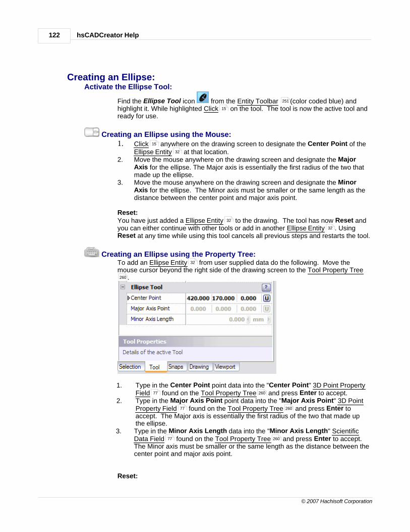
hsCADCreator Help122
© 2007 Hachisoft Corporation
Creating an Ellipse:Activate the Ellipse Tool:
Find the Ellipse Tool icon from the Entity Toolbar (color coded blue) andhighlight it. While highlighted Click on the tool. The tool is now the active tool andready for use.
Creating an Ellipse using the Mouse:1. Click anywhere on the drawing screen to designate the Center Point of the
Ellipse Entity at that location.2. Move the mouse anywhere on the drawing screen and designate the Major
Axis for the ellipse. The Major axis is essentially the first radius of the two thatmade up the ellipse.
3. Move the mouse anywhere on the drawing screen and designate the MinorAxis for the ellipse. The Minor axis must be smaller or the same length as thedistance between the center point and major axis point.
Reset:You have just added a Ellipse Entity to the drawing. The tool has now Reset andyou can either continue with other tools or add in another Ellipse Entity . UsingReset at any time while using this tool cancels all previous steps and restarts the tool.
Creating an Ellipse using the Property Tree: To add an Ellipse Entity from user supplied data do the following. Move themouse cursor beyond the right side of the drawing screen to the Tool Property Tree
.
1. Type in the Center Point point data into the "Center Point" 3D Point PropertyField found on the Tool Property Tree and press Enter to accept.
2. Type in the Major Axis Point point data into the "Major Axis Point" 3D PointProperty Field found on the Tool Property Tree and press Enter toaccept. The Major axis is essentially the first radius of the two that made upthe ellipse.
3. Type in the Minor Axis Length data into the "Minor Axis Length" ScientificData Field found on the Tool Property Tree and press Enter to accept.The Minor axis must be smaller or the same length as the distance between thecenter point and major axis point.
Reset:
251
15
15
32
32
32
32
260
77 260
77 260
77 260

Handbook 123
© 2007 Hachisoft Corporation
You have just added a Ellipse Entity to the drawing. The tool has now Reset andyou can either continue with other tools or add in another Ellipse Entity . UsingReset at any time while using this tool cancels all previous steps and restarts the tool.
Tool Options:
Escape (Esc): key cancels current tool and activates the default tool (Selection Tool).
Space: key Resets this tool.
Also See:Ellipse EntityGridGrid SnapsEntity SnapsNotification Bar
2.2.2.2.9 Dimension Tool
Entity toolbar :
The Dimension Tool is responsible for creating Dimension Entities .
Creating a Dimension:
Activate a Dimension Tool:
Find one of the Dimension Line Tool icons from the EntityToolbar (color coded blue) and highlight it. While highlighted Click on the tool.The tool is now the active tool and ready for use. This set of tools is part of a Flyouttoolbar .
Creating the Dimension Line:There are six different types of Dimension Line tools available to create various typesof Dimension Lines .
1. Aligned Dimension Tool (default) : A Linear dimension for objects withunusual shapes, or with edges at unusual angles; the dimension line willalways parallel the imaginary line connecting the origins of the extensionlines.
2. Linear Dimension Tool : Linear dimension that will either be orientedalong either the X-axis or the Y-axis (your choice).
3. Ordinate Dimension Tool : Dimension of an X-axis or Y-axis point. (yourchoice)
4. Radial Dimension Tool : Dimension for the radius of a circle.
32
32
101
32
75
74
72
267
251
33
251 15
81
33
124
126
128
130

hsCADCreator Help124
© 2007 Hachisoft Corporation
5. Diametric Dimension Tool : Dimension for the diameter of a circle.
6. Angular Dimension Tool : Dimension for an angle (in radians or degrees).
Also See: Dimension EntityManage Dimension StylesFlyout Toolbar
2.2.2.2.9.1 Aligned Dimension Tool
Entity toolbar :
The Aligned Dimension Tool is responsible for creating Dimension Entities that lay alongside theentity or spacing they display a dimension for.
Creating an Aligned Dimension:Activate the Aligned Dimension Tool:
Find the Aligned Dimension Tool icon from the Entity Toolbar (color codedblue) or Dimension Flyout Toolbar and highlight it. While highlighted Click onthe tool. The tool is now the active tool and ready for use.
Creating an Aligned Dimension using the Mouse:
1. Click anywhere on the drawing screen to designate the Start Point of theDimension at that location.
2. Move the mouse and Click on a point you desire to be the End Point. Thedefault dimension text will be the distance between this point and the StartPoint.
3. Move the mouse and Click on a point you wish to designate as the OffsetPoint. This point is the basis for offsetting the notation of the dimension awayfrom the dimensioned entity or space.
Reset:You have just added an Aligned Dimension Entity to the drawing using a StartPoint, End Point, and Offset Point. The tool has now Reset and you can eithercontinue with other tools or add in another Aligned Dimension Entity . Using Resetat any time while using this tool cancels all previous steps and restarts the tool.
Creating an Aligned Dimension using the Property Tree: To add an Aligned Dimension from user supplied data, do the following . Movethe mouse cursor beyond the right side of the drawing screen to the Tool Property
132
134
33
221
81
251
33
251
81 15
15
15
15
35
35
35

Handbook 125
© 2007 Hachisoft Corporation
Tree .
1. Type in the Start Point point data into the "Start Point" 3D Point Property Field found on the Tool Property Tree and press Enter to accept. This will
position the starting point for the dimension.2. Type in the End Point point data into the "End Point" 3D Point Property Field
found on the Tool Property Tree and press Enter to accept. 3. Type in the Offset Point point data into the "Offset Point" 3D Point Property
Field found on the Tool Property Tree and press Enter to accept. Thiswill finish the Aligned Dimension Entity creation process. If in Show UnitMode the resultant dimension text will have the current unit displayed.
Reset:You have just added an Aligned Dimension Entity to the drawing using a StartPoint, End Point, and Offset Point. The tool has now Reset and you can eithercontinue with other tools or add in another Dimension Entity . Using Reset at anytime while using this tool cancels all previous steps and restarts the tool.
Tool Options:
Tab: Auto snap Enabled key enables/disables the auto snap feature. Auto snapautomatically enables the end, mid, nearest and quadrant Entity Snap features.
Show Unit will display the dimension's unit within the Dimension Entity's text.
Escape (Esc): key cancels current tool and activates the default tool (Selection Tool).
Space: key Resets this tool.
Also See:Dimension EntityManage Dimension StylesGridGrid SnapsEntity SnapsNotification BarFlyout Toolbar
260
77 260
77 260
77 260
33
33
33
72
101
33
221
75
74
72
267
81

hsCADCreator Help126
© 2007 Hachisoft Corporation
2.2.2.2.9.2 Linear Dimension Tool
Entity toolbar :
The Linear Dimension Tool is responsible for creating Linear Dimension Entities that representthe distance between two points either along the X-Axis or Y-Axis.
Creating a Linear Dimension:Activate the Aligned Dimension Tool:
Find the Linear Dimension Tool icon from the Entity Toolbar (color codedblue) or Dimension Flyout Toolbar and highlight it. While highlighted Click onthe tool. The tool is now the active tool and ready for use.
Creating a Linear Dimension using the Mouse:
1. Click anywhere on the drawing screen to designate the Start Point of theDimension at that location.
2. Move the mouse and Click on a point you desire to be the End Point. If inOn Y Axis Mode the dimension will represent the distance between this pointand the Start Point along the Y-Axis. If in On X Axis Mode the dimension willrepresent the distance between this point and the Start Point along the X-Axis.
3. Move the mouse and Click on a point you wish to designate as the OffsetPoint. This point is the basis for offsetting the notation of the dimension awayfrom the dimensioned entity or space. The Dimension text will be positionedparallel to the axis of measurement
Reset:You have just added a Linear Dimension Entity to the drawing using a Start Point,End Point, and Offset Point. The tool has now Reset and you can either continuewith other tools or add in another Linear Dimension Entity . Using Reset at anytime while using this tool cancels all previous steps and restarts the tool.
Creating an Linear Dimension using the Property Tree: To add an Linear Dimension from user supplied data, do the following . Move themouse cursor beyond the right side of the drawing screen to the Tool Property Tree
.
251
36
251
81 15
15
15
15
36
36
36
260

Handbook 127
© 2007 Hachisoft Corporation
1. Type in the Start Point point data into the "Start Point" 3D Point Property Field found on the Tool Property Tree and press Enter to accept. This will
position the starting point for the linear dimension.2. Type in the End Point point data into the "End Point" 3D Point Property Field
found on the Tool Property Tree and press Enter to accept. If in On YAxis Mode the dimension will represent the distance between this point andthe Start Point along the Y-Axis. If in On X Axis Mode the dimension willrepresent the distance between this point and the Start Point along the X-Axis.
3. Type in the Offset Point point data into the "Offset Point" 3D Point PropertyField found on the Tool Property Tree and press Enter to accept. TheDimension text will be positioned parallel to the axis of measurement. Onacceptance the Linear Dimension Entity creation process will be complete.If in Show Unit Mode the resultant dimension text will have the current unitdisplayed.
Reset:You have just added a Linear Dimension Entity to the drawing using a Start Point,End Point, and Offset Point. The tool has now Reset and you can either continuewith other tools or add in another Dimension Entity . Using Reset at any time whileusing this tool cancels all previous steps and restarts the tool.
Tool Options:
Tab: Auto snap Enabled key enables/disables the auto snap feature. Auto snapautomatically enables the end and mid Entity Snap features.
Show Unit will display the dimension's unit within the Dimension Entity's text.
Escape (Esc): key cancels current tool and activates the default tool (Selection Tool).
Space: key Resets this tool.
77 260
77 260
77 260
33
33
33
72
33
101

hsCADCreator Help128
© 2007 Hachisoft Corporation
Also See:Dimension EntityManage Dimension StylesGridGrid SnapsEntity SnapsNotification BarFlyout Toolbar
2.2.2.2.9.3 Ordinate Dimension Tool
Entity toolbar :
The Ordinate Dimension Tool is responsible for creating Ordinate Dimension Entities .
Creating an Ordinate Dimension :Activate Ordinate Dimension Tool:
Find the Ordinate Dimension Tool icon from the Entity Toolbar (color codedblue) or Dimension Flyout Toolbar and highlight it. While highlighted Click onthe tool. The tool is now the active tool and ready for use.
Creating an Ordinate Dimension using the Mouse:
1. Click anywhere on the drawing screen to designate the Start Point of theDimension at that location.
2. Move the mouse and Click on a point you desire to be the End Point. If inOn Y Axis Mode the dimension will represent the distance between this pointand the Start Point along the Y-Axis. If in On X Axis Mode the dimension willrepresent the distance between this point and the Start Point along the X-Axis.
3. Move the mouse and Click on a point you wish to designate as the InsertionPoint. This point is the basis for positioning the dimension text.
Creating an Ordinate Dimension using the Property Tree: To add an Ordinate Dimension from user supplied data, do the following . Movethe mouse cursor beyond the right side of the drawing screen to the Tool Property
33
221
75
74
72
267
81
251
38
251
81 15
15
15
15
38

Handbook 129
© 2007 Hachisoft Corporation
Tree .
1. Type in the Start Point point data into the "Start Point" 3D Point Property Field found on the Tool Property Tree and press Enter to accept. This will
position the starting point for the dimension.2. Type in the End Point point data into the "End Point" 3D Point Property Field
found on the Tool Property Tree and press Enter to accept. If in On YAxis Mode the dimension will represent the distance between this point andthe Start Point along the Y-Axis. If in On X Axis Mode the dimension willrepresent the distance between this point and the Start Point along the X-Axis.
3. Type in the Insertion Point point data into the "Insertion Point" 3D PointProperty Field found on the Tool Property Tree and press Enter toaccept. The Dimension text will be positioned at this point. On acceptance the Ordinate Dimension Entity creation process will be complete. If in ShowUnit Mode the resultant dimension text will have the current unit displayed.
Reset:You have just added an Ordinate Dimension Entity to the drawing using a StartPoint, End Point, and Offset Point. The tool has now Reset and you can eithercontinue with other tools or add in another Ordinate Dimension Entity . UsingReset at any time while using this tool cancels all previous steps and restarts thetool.
Tool Options:
Tab: Auto snap Enabled key enables/disables the auto snap feature. Auto snapautomatically enables the end and nearest Entity Snap features.
Show Unit will display the dimension's unit within the Dimension Entity's text.
Escape (Esc): key cancels current tool and activates the default tool (Selection Tool).
Space: key Resets this tool.
260
77 260
77 260
77 260
38
38
38
72
33
101

hsCADCreator Help130
© 2007 Hachisoft Corporation
Also See:Dimension EntityManage Dimension StylesGridGrid SnapsEntity SnapsNotification BarFlyout Toolbar
2.2.2.2.9.4 Radial Dimension Tool
Entity toolbar :
The Radial Dimension Tool is responsible for creating Radial Dimension Entities .
Creating an Radial Dimension :Activate Radial Dimension Tool:
Find the Radial Dimension Tool icon from the Entity Toolbar (color codedblue) or Dimension Flyout Toolbar and highlight it. While highlighted Click onthe tool. The tool is now the active tool and ready for use.
Creating an Radial Dimension using the Mouse:
1. Click anywhere on the drawing screen to designate the Center Point of theDimension at that location.
2. Move the mouse and Click on a point you desire to be the Chord Point.This is the Chord Point from which an extension line will reach. The distancebetween Center Point and Chord Point will be the radius measurement value.
3. Move the mouse and Click on at a distance you wish to designate as theOffset Distance. This distance is the basis for offsetting the notation of thedimension away from the dimensioned entity.
Creating an Radial Dimension using the Property Tree: To add an Radial Dimension from user supplied data, do the following . Move themouse cursor beyond the right side of the drawing screen to the Tool Property Tree
.
33
221
75
74
72
267
81
251
39
251
81 15
15
15
15
39
260

Handbook 131
© 2007 Hachisoft Corporation
1. Type in the Center Point point data into the "Center Point" 3D Point PropertyField found on the Tool Property Tree and press Enter to accept. Thiswill position the center point for the dimension.
2. Type in the Chord Point point data into the "Chord Point" 3D Point PropertyField found on the Tool Property Tree and press Enter to accept.
3. Type in the Offset Distance data into the "Offset Distance" Scientific DataField found on the Tool Property Tree and press Enter to accept. TheDimension text will be positioned at this much offset distance away from chordpoint. On acceptance the Radial Dimension Entity creation process will becomplete. If in Show Unit Mode the resultant dimension text will have thecurrent unit displayed.
Reset:You have just added an Radial Dimension Entity to the drawing using a ChordPoint, End Point, and Offset Point. The tool has now Reset and you can eithercontinue with other tools or add in another Radial Dimension Entity . Using Resetat any time while using this tool cancels all previous steps and restarts the tool.
Tool Options:
Tab: Auto snap Enabled key enables/disables the auto snap feature. Auto snapautomatically enables the end, mid, nearest and center Entity Snap features.
Show Unit will display the dimension's unit within the Dimension Entity's text.
Escape (Esc): key cancels current tool and activates the default tool (Selection Tool).
Space: key Resets this tool.
Also See:Dimension EntityManage Dimension StylesGridGrid SnapsEntity SnapsNotification BarFlyout Toolbar
77 260
77 260
77 260
39
39
38
72
33
101
33
221
75
74
72
267
81

hsCADCreator Help132
© 2007 Hachisoft Corporation
2.2.2.2.9.5 Diametric Dimension Tool
Entity toolbar :
The Diametric Dimension Tool is responsible for creating Diametric Dimension Entities .
Creating an Diametric Dimension :Activate Diametric Dimension Tool:
Find the Diametric Dimension Tool icon from the Entity Toolbar (colorcoded blue) or Dimension Flyout Toolbar and highlight it. While highlighted Click
on the tool. The tool is now the active tool and ready for use.
Creating an Diametric Dimension using the Mouse:
1. Click anywhere on the drawing screen to designate the Far Chord Point ofthe Dimension at that location.
2. Move the mouse and Click on a point you desire to be the Chord Point.This is the Chord Point from which an extension line will reach. The distancebetween Far Chord Point and Chord Point will be the diameter measurementvalue.
3. Move the mouse and Click on at a distance you wish to designate as theOffset Distance. This distance is the basis for offsetting the notation of thedimension away from the dimensioned entity.
Creating an Diametric Dimension using the Property Tree: To add an Diametric Dimension Entities from user supplied data, do the following . Move the mouse cursor beyond the right side of the drawing screen to the ToolProperty Tree .
251
41
251
81
15
15
15
15
41
260
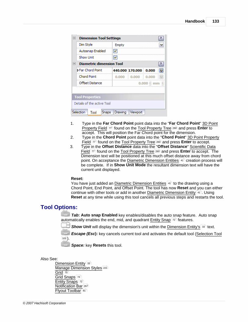
Handbook 133
© 2007 Hachisoft Corporation
1. Type in the Far Chord Point point data into the "Far Chord Point" 3D PointProperty Field found on the Tool Property Tree and press Enter toaccept. This will position the Far Chord point for the dimension.
2. Type in the Chord Point point data into the "Chord Point" 3D Point PropertyField found on the Tool Property Tree and press Enter to accept.
3. Type in the Offset Distance data into the "Offset Distance" Scientific DataField found on the Tool Property Tree and press Enter to accept. TheDimension text will be positioned at this much offset distance away from chordpoint. On acceptance the Diametric Dimension Entities creation process willbe complete. If in Show Unit Mode the resultant dimension text will have thecurrent unit displayed.
Reset:You have just added an Diametric Dimension Entities to the drawing using aChord Point, End Point, and Offset Point. The tool has now Reset and you can eithercontinue with other tools or add in another Diametric Dimension Entity . UsingReset at any time while using this tool cancels all previous steps and restarts the tool.
Tool Options:
Tab: Auto snap Enabled key enables/disables the auto snap feature. Auto snapautomatically enables the end, mid, and quadrant Entity Snap features.
Show Unit will display the dimension's unit within the Dimension Entity's text.
Escape (Esc): key cancels current tool and activates the default tool (Selection Tool).
Space: key Resets this tool.
Also See:Dimension EntityManage Dimension StylesGridGrid SnapsEntity SnapsNotification BarFlyout Toolbar
77 260
77 260
77 260
41
41
41
72
33
101
33
221
75
74
72
267
81

hsCADCreator Help134
© 2007 Hachisoft Corporation
2.2.2.2.9.6 Angular Dimension Tool
Entity toolbar :
The Angular Dimension Tool is responsible for creating Angular Dimension Entities .
Creating an Angular Dimension :Activate Angular Dimension Tool:
Find the Angular Dimension Tool icon from the Entity Toolbar (color codedblue) or Dimension Flyout Toolbar and highlight it. While highlighted Click onthe tool. The tool is now the active tool and ready for use.
Creating an Angular Dimension using the Mouse:
1. Click anywhere on the drawing screen to designate the Center Point of theDimension at that location.
2. Move the mouse and Click on a point you desire to be the Start Point. Thisis the point from which the angle will be measured with reference to CenterPoint.
3. Move the mouse and Click on a point you desire to be the End Point. This isthe point to which the angle will be measured with reference to Center Point.
4. Move the mouse and Click on one side of Center Point. The angle betweenStart Point and End Point will measured on this side of the Center Point.
Creating an Angular Dimension using the Property Tree: To add an Angular Dimension Entities from user supplied data, do the following .Move the mouse cursor beyond the right side of the drawing screen to the ToolProperty Tree .
251
42
251
81 15
15
15
15
15
42
260

Handbook 135
© 2007 Hachisoft Corporation
1. Type in the Center Point point data into the "Center Point" 3D Point PropertyField found on the Tool Property Tree and press Enter to accept. Thiswill position the Center Point for the dimension.
2. Type in the Start Point point data into the "Start Point" 3D Point Property Field found on the Tool Property Tree and press Enter to accept.
3. Type in the End Point point data into the "End Point" 3D Point Property Field found on the Tool Property Tree and press Enter to accept.
4. Type in the Offset Side Point point data into the "Offset Side Point" 3D PointProperty Field found on the Tool Property Tree and press Enter toaccept.
Reset:You have just added an Angular Dimension Entities to the drawing using a ChordPoint, End Point, and Offset Point. The tool has now Reset and you can eithercontinue with other tools or add in another Angular Dimension Entity . Using Resetat any time while using this tool cancels all previous steps and restarts the tool.
Tool Options:
Tab: Auto snap Enabled key enables/disables the auto snap feature. Auto snapautomatically enables the end, mid, nearest and center Entity Snap features.
Show Unit will display the dimension's unit within the Dimension Entity's text.
Escape (Esc): key cancels current tool and activates the default tool (Selection Tool).
Space: key Resets this tool.
Also See:Dimension EntityManage Dimension StylesGridGrid SnapsEntity SnapsNotification BarFlyout Toolbar
77 260
77 260
77 260
77 260
42
42
72
33
101
33
221
75
74
72
267
81

hsCADCreator Help136
© 2007 Hachisoft Corporation
2.2.2.2.10 Text Tool
Entity toolbar :
The Text Tool is responsible for creating Text Entities .
Creating a Text:Activate the Text Tool:
Find the Text Tool icon from the Entity Toolbar (color coded blue) andhighlight it. While highlighted Click on the tool. The tool is now the active tool andready for use.
Creating an Text using the Mouse:
1. Click anywhere on the drawing screen to designate the Position of the TextEntity at that location.
2. Move the mouse cursor beyond right side of the drawing screen to theTool Property Tree and enter Text data in "Text" property field and pressEnter.
If "Specify rotation" is selected:Move the mouse cursor on drawing screen and Click where required
rotation is set.If "Specify height" is selected:
Move the mouse cursor on drawing screen and Click where required heightis set.
Reset:You have just added a Text Entity to the drawing. The tool has now Reset andyou can either continue with other tools or add in another Text Entity . Using Resetat any time while using this tool cancels all previous steps and restarts the tool.
Creating an Text using the Property Tree: To add an Text Entity from user supplied data do the following. Move the mousecursor beyond the right side of the drawing screen to the Tool Property Tree .
251
43
251
15
15
43
260
15
15
43
43
43
260

Handbook 137
© 2007 Hachisoft Corporation
1. Type in the Position Point point data into the "Position" 3D Point PropertyField found on the Tool Property Tree and press Enter to accept.
2. Type in the Text data into the "Text" property found on the Tool Property Tree and press Enter to accept.
3. Type in the Rotation angle data into the "Rotation" Scientific Data Fieldfound on the Tool Property Tree and press Enter to accept.
4. Type in the Text height data into the "Text Height" Scientific Data Fieldfound on the Tool Property Tree and press Enter to accept.
Reset:You have just added a Text Entity to the drawing. The tool has now Reset andyou can either continue with other tools or add in another Text Entity . UsingReset at any time while using this tool cancels all previous steps and restarts the tool.
Tool Options:
Escape (Esc): key cancels current tool and activates the default tool (Selection Tool).
Space: key Resets this tool.
Also See:Text EntityText StylesGridGrid SnapsEntity SnapsNotification Bar
77 260
260
77
260
77
260
43
43
101
43
239
75
74
72
267

hsCADCreator Help138
© 2007 Hachisoft Corporation
2.2.2.2.11 Hatch Tool
Entity toolbar :
The Hatch Tool is responsible for creating Hatch Entities .
Creating a Hatch:Activate the Hatch Tool:
Find the Hatch Tool icon from the Entity Toolbar (color coded blue) andhighlight it. While highlighted Click on the tool. The tool is now the active tool andready for use.
Creating an Hatch using the Mouse:
1. Click anywhere inside the region to be hatched for the Hatch Entity .
2. Press Enter to create hatch.
Reset:You have just added a Hatch Entity to the drawing. The tool has now Reset andyou can either continue with other tools or add in another Hatch Entity . UsingReset at any time while using this tool cancels all previous steps and restarts the tool.
Creating an Hatch using the Property Tree: Create Hatch tool currently doesn't support input from keyboard to specify region for
Hatch Entity .
251
45
251
15
15 45
45
45
45

Handbook 139
© 2007 Hachisoft Corporation
Tool Options:
Escape (Esc): key cancels current tool and activates the default tool (Selection Tool).
Space: key Resets this tool.
Also See:Hatch EntityHatch StylesGridGrid SnapsEntity SnapsNotification Bar
2.2.2.2.12 Poly Face Mesh Tool
Entity toolbar :
The Poly Face Mesh Tool is responsible for creating Poly Face Mesh Entities .
Creating a Face Mesh:Activate the Face Mesh Tool:
Find the Poly Face Mesh Tool icon from the Entity Toolbar (color codedblue) and highlight it. While highlighted Click on the tool. The tool is now theactive tool and ready for use.
Creating an Face Mesh using the Mouse:
1. Click anywhere inside the region to be Face Mesh for the Poly Face MeshEntity .
2. Press Enter to create Poly Face Mesh.
Reset:You have just added a Poly Face Mesh Entity to the drawing. The tool has nowReset and you can either continue with other tools or add in another Poly Face MeshEntity . Using Reset at any time while using this tool cancels all previous steps andrestarts the tool.
101
43
60
75
74
72
267
251
46
251
15
15
46
46
46

hsCADCreator Help140
© 2007 Hachisoft Corporation
Creating an Face Mesh using the Property Tree: Create Face Mesh tool currently doesn't support input from keyboard to specify region
for Poly Face Mesh Entity .
Tool Options:
Escape (Esc): key cancels current tool and activates the default tool (Selection Tool).
Space: key Resets this tool.
Also See:Poly Face Mesh EntitiesGridGrid SnapsEntity SnapsNotification Bar
2.2.2.2.13 Block Definition Tool
Entity toolbar :
The Block Definition Tool is responsible for creating Block Definition Entities .
Creating a Block Definition:Activate the Block Definition Tool:
Find the Block Definition Tool icon from the Entity Toolbar (color codedblue) and highlight it. While highlighted Click on the tool. The tool is now theactive tool and ready for use.
Selecting the Entities to create Block Definition:This tool is a Stacked tool . If there is no selection prior to the activation of this toolthe Selection Tool will become active and allow the selection of the entities thatwill be used to create block. 1. Select Entities to be to create Block Definition Entity .2. Press Enter to finish the Selection Tool .
Creating an Block Definition using the Mouse:
46
101
46
75
74
72
267
251
61
251
15
15
101
61
101

Handbook 141
© 2007 Hachisoft Corporation
1. Move the mouse cursor beyond right side of the drawing screen to theTool Property Tree and enter Block Name data in "Block Name" propertyfield and press Enter.
2. Click anywhere on the drawing screen to designate the Block Origin of theBlock Definition Entity at that location. This Block Origin is considered asbase point for insertion whenever this block gets inserted into drawing.
Reset:You have just added a Block Definition Entity to the drawing. The tool has nowReset and you can either continue with other tools or add in another Block DefinitionEntity . Using Reset at any time while using this tool cancels all previous steps andrestarts the tool.
Creating an Block Definition using the Property Tree: To add an Block Definition Entity from user supplied data do the following. Movethe mouse cursor beyond the right side of the drawing screen to the Tool PropertyTree .
1. If do not have any entities selected, Select entities that defines new block.Press Enter when finished with selection.
2. Type in the Block Name data in "Block Name" property field and press Enter.3. Type in the Block Origin point data into the "Block Origin" 3D Point Property
Field found on the Tool Property Tree and press Enter to accept.
Reset:You have just added a Block Definition Entity to the drawing. The tool has nowReset and you can either continue with other tools or add in another Block DefinitionEntity . Using Reset at any time while using this tool cancels all previous stepsand restarts the tool.
Tool Options:
Escape (Esc): key cancels current tool and activates the default tool (Selection Tool).
Space: key Resets this tool.
Also See:Block Definition Entity
260
15
61
61
61
61
260
101
77 260
61
61
101
61

hsCADCreator Help142
© 2007 Hachisoft Corporation
GridGrid SnapsEntity SnapsNotification Bar
2.2.2.2.14 Block Insertion Tool
Entity toolbar :
The Block Insertion Tool is responsible for creating Block Insertion Entities .
Creating a Block Insertion:Activate the Block Insertion Tool:
Find the Block Insertion Tool icon from the Entity Toolbar (color coded blue)and highlight it. While highlighted Click on the tool. The tool is now the active tooland ready for use.
Creating an Block Insertion using the Mouse:
1. If do not have Block Definition selected, move the mouse cursor beyondright side of the drawing screen to the Tool Property Tree and select BlockDefinition to be inserted.
2. Click anywhere on the drawing screen to designate the Insertion Point ofthe Block Insertion Entity at that location.
If Scale Mode is other than "Retain original Scale":Move the mouse cursor on drawing screen and Click where required ScaleFactors are set.
If Rotate Mode is selected:Move the mouse cursor on drawing screen and Click where required RotationAngle is set.
Reset:You have just added a Block Insertion Entity to the drawing. The tool has nowReset and you can either continue with other tools or add in another Block InsertionEntity . Using Reset at any time while using this tool cancels all previous steps andrestarts the tool.
Creating an Block Insertion using the Property Tree: To add an Block Insertion Entity from user supplied data do the following. Movethe mouse cursor beyond the right side of the drawing screen to the Tool PropertyTree .
75
74
72
267
251
46
251
15
61
260
61
15
46
15
15
46
46
61
260

Handbook 143
© 2007 Hachisoft Corporation
1. If do not have Block Definition selected, select Block Definition to beinserted.
2. Type in the Insertion point data into the "Insertion Point" 3D Point PropertyField found on the Tool Property Tree and press Enter to accept.
If Scale Mode is other than "Retain original Scale":Type in the Scaling data in "Scale Factors" property field and press Enter.
If Rotate Mode is selected:Type in the required rotation angle in "Rotation Angle" scientific data
property field and press Enter.
Reset:You have just added a Block Insertion Entity to the drawing. The tool has nowReset and you can either continue with other tools or add in another Block InsertionEntity . Using Reset at any time while using this tool cancels all previous stepsand restarts the tool.
Tool Options:
Escape (Esc): key cancels current tool and activates the default tool (Selection Tool).
Space: key Resets this tool.
Also See:Block Insertion EntityBlock ManagementGridGrid SnapsEntity SnapsNotification Bar
61 61
77 260
78
46
46
101
46
218
75
74
72
267

hsCADCreator Help144
© 2007 Hachisoft Corporation
2.2.2.2.15 Image Insertion Tool
Entity toolbar :
The Image Insertion Tool is responsible for creating Image Insertion Entities .
Creating a Image Insertion:Activate the Image Insertion Tool:
Find the Image Insertion Tool icon from the Entity Toolbar (color codedblue) and highlight it. While highlighted Click on the tool. The tool is now theactive tool and ready for use.
Creating an Image Insertion using the Mouse:
1. If do not have Image Definition selected, move the mouse cursor beyondright side of the drawing screen to the Tool Property Tree and select ImageDefinition to be inserted.
2. Click anywhere on the drawing screen to designate the Insertion Point ofthe Image Insertion Entity at that location.
If Specify Scale is Selected:Move the mouse cursor on drawing screen and Click where required ScaleFactors are set.
If Specify Rotation is selected:Move the mouse cursor on drawing screen and Click where required RotationAngle is set.
Reset:You have just added a Image Insertion Entity to the drawing. The tool has nowReset and you can either continue with other tools or add in another Image InsertionEntity . Using Reset at any time while using this tool cancels all previous steps andrestarts the tool.
Creating an Image Insertion using the Property Tree: To add an Image Insertion Entity from user supplied data do the following. Movethe mouse cursor beyond the right side of the drawing screen to the Tool PropertyTree .
251
47
251
15
63
260
63
15
47
15
15
47
47
61
260

Handbook 145
© 2007 Hachisoft Corporation
1. If do not have Image Definition selected, select Image Definition to beinserted.
2. Type in the Insertion point data into the "Insertion Point" 3D Point PropertyField found on the Tool Property Tree and press Enter to accept.
If Specify Scale is Selected:Type in the Scaling data in "Scale Factors" property field and press Enter.
If Specify Rotation is selected:Type in the required rotation angle in "Rotation Angle" scientific data
property field and press Enter.
Reset:You have just added a Image Insertion Entity to the drawing. The tool has nowReset and you can either continue with other tools or add in another Image InsertionEntity . Using Reset at any time while using this tool cancels all previous stepsand restarts the tool.
Tool Options:
Escape (Esc): key cancels current tool and activates the default tool (Selection Tool).
Space: key Resets this tool.
Also See:Image Insertion EntityImage ManagementGridGrid Snaps
61 61
77 260
78
47
47
101
47
228
75
74

hsCADCreator Help146
© 2007 Hachisoft Corporation
Entity SnapsNotification Bar
2.2.2.2.16 Viewport Tool
Entity toolbar :
The Viewport Tool is responsible for creating Viewport Entities .
Creating a Viewport:Activate the Viewport Tool:
Activate paperspace layout (Layout1 or Layout2) by clicking small arrow button onbottom edge of drawing screen or select paperspace layout from Drawing Settings
. Find the Viewport Tool icon from the Entity Toolbar (color coded blue) andhighlight it. While highlighted Click on the tool. The tool is now the active tool andready for use.
Creating an Viewport using the Mouse:
1. Click anywhere on the drawing screen to designate the Start Point of theViewport Entity at that location. Start Point left hand top/bottom corner forviewport.
2. Click anywhere on the drawing screen to designate the Width of theViewport Entity at that location.
3. Click anywhere on the drawing screen to designate the Height of theViewport Entity at that location.
Reset:You have just added a Viewport Entity to the drawing. The tool has now Resetand you can either continue with other tools or add in another Viewport Entity .Using Reset at any time while using this tool cancels all previous steps and restartsthe tool.
Creating an Viewport using the Property Tree: To add an Viewport Entity from user supplied data do the following. Move themouse cursor beyond the right side of the drawing screen to the Tool Property Tree
.
72
267
251
49
76
251
15
15
49
15
49
15
49
49
49
61
260

Handbook 147
© 2007 Hachisoft Corporation
1. Type in the Start point data into the "Start Point" 3D Point Property Fieldfound on the Tool Property Tree and press Enter to accept.
2. Type in the Viewport width data into the "Width" Scientific Data Field foundon the Tool Property Tree and press Enter to accept.
3. Type in the Viewport height data into the "Height" Scientific Data Fieldfound on the Tool Property Tree and press Enter to accept.
Reset:You have just added a Viewport Entity to the drawing. The tool has now Resetand you can either continue with other tools or add in another Viewport Entity .Using Reset at any time while using this tool cancels all previous steps and restartsthe tool.
Tool Options:
Escape (Esc): key cancels current tool and activates the default tool (Selection Tool).
Space: key Resets this tool.
Also See:Viewport EntityViewport ManagementGridGrid SnapsEntity SnapsNotification Bar
2.2.2.3 Modify Tools
hsCADCreator has eight different tools available to modify/edit drawing entities. The Modify Toolscan be accessed by using the green colored Modify Toolbar , or by accessing the Modify optionfrom the Tool Menu . The Modify tools primary function is to allow the modification of drawingentities through a user friendly process of steps.
77
260
77
260
77
260
49
49
101
49
242
75
74
72
267
253
97

hsCADCreator Help148
© 2007 Hachisoft Corporation
1. Translate Tool Facilitates the linear movement of an object in 3D space
2. Rotate Tool Facilitates the rotational movement of an object about a specified location
3. Explode Tool Facilitates the breaking down of entities into their simple components
4. Delete Tool Facilitates the removal of selected entities from the drawing.
5. Scale Entities Uniformly Tool : Facilitates entire created entities to be resizedproportionately
6. Scale Entities Non-uniformly Tool : Facilitates portions of created entities to be resizeddisproportionately
7. Trim Tool : Facilitates the removal of unnecessary portions of a created entity
8. Extend Tool : Facilitates the elongation of selected portions of a created entity
9. Clone Tools : Facilitates creation of multiple copies of selected entities
a. Linear Clone
b. Planar Clone
c. 3-Axial Clone
d. Radial Clone
2.2.2.3.1 Translate Tool
Modify Toolbar :
In hsCADCreator the Translate Tool facilitates movement of one or more entire entities from onelocation to another.
Translating Entities:Activate the Translate Tool:
Find the Translate Tool icon from the Modify Toolbar (color coded green) andhighlight it. While highlighted Click on the tool. The tool is now the active tool and readyfor use.
Note: If there is a selection prior to activating the Translate tool the Selection Steps will beskipped.
148
198
152
153
154
155
157
158
159
163
165
168
160
253
253
15

Handbook 149
© 2007 Hachisoft Corporation
Selecting the Entities to Translate:This tool is a Stacked tool . If there is no selection prior to the activation of this toolthe Selection Tool will become active and allow the selection of the entities thatwill be translated. 1. Select Entities to be Translated.2. Press Enter to finish the Selection Tool .
Translate Selected Entities using Mouse: 1. Move the mouse and Click anywhere on the screen. This will be the Base
Point from which the selected entities will move in relation to.2. Move the mouse until the selected entities are placed as desired and Click to
finish placement. If in either Along X-Axis Mode, Along Y-Axis Mode, orAlong Z-Axis Mode the translation is restricted to that axis.
Reset:You have just translated the selected Entity(ies). The tool has now Reset and youcan either continue with other tools or translate the entity(ies) again.
Translate Selected Entities using Property Tree:
To Translate the selected entities in a more precise manner do the following. Movethe mouse cursor beyond the right side of the drawing screen to the Tool PropertyTree .
1. Type in the Base Point point data into the "Base Point" 3D Point PropertyField found on the Tool Property Tree and press Enter to accept.
2. Type in the Move To Point point data into the "Move To Point" 3D PointProperty Field found on the Tool Property Tree and press Enter toaccept. If in either Along X-Axis Mode, Along Y-Axis Mode, or Along Z-AxisMode the translation is restricted to that axis.
Reset:You have just translated the selected Entity(ies). The tool has now Reset and youcan either continue with other tools or translate the entity(ies) again.
15
101
101
15
260
77 260
77 260

hsCADCreator Help150
© 2007 Hachisoft Corporation
Tool Options:Relative Distance field displays the relative distance this translate will be for the selectedentities.Along X-Axis mode restricts translation along the X-Axis.Along Y-Axis mode restricts translation along the Y-Axis.Along Z-Axis mode restricts translation along the Z-Axis.
Escape (Esc): key cancels current tool and activates the default tool (Selection Tool).
Space: key Resets this tool.
Also See:Selection ToolGridGrid SnapsEntity SnapsNotification Bar
2.2.2.3.2 Rotate Tool
Modify Toolbar :
In hsCADCreator the Rotate Tool facilitates movement of entire entities about a fixed point.
Rotating Entities:Activate the Rotate Tool:
Find the Rotate Tool icon from the Modify Toolbar (color coded green) andhighlight it. While highlighted Click on the tool. The tool is now the active tool and readyfor use.
Note: If there is a selection prior to activating the Translate tool the Selection Steps will beskipped.
Selecting the Entities to Rotate:This tool is a Stacked tool . If there is no selection prior to the activation of this toolthe Selection Tool will become active and allow the selection of the entities thatwill be translated. 1. Select Entities to be Rotate.2. Press Enter to finish the Selection Tool .
Rotate Selected Entities using Mouse: 1. Move the mouse and Click anywhere on the screen. This will be the Base
Point from which the selected entities will move in relation to.2. Click and hold the left mouse button down. Move the mouse while holding
the left button down until the selected entities are placed as desired and releasethe mouse button. If in either X-Axis Mode, Y-Axis Mode, or Z-Axis Mode therotation is restricted to that axis.
101
101
75
74
72
267
253
253
15
15
101
101
15
15

Handbook 151
© 2007 Hachisoft Corporation
Reset:You have just Rotated the selected Entity(ies). The tool has now Reset and you caneither continue with other tools or rotate the entity(ies) again.
Rotate Selected Entities using Property Tree:
To Rotate the selected entity(ies) in a more precise manner do the following. Movethe mouse cursor beyond the right side of the drawing screen to the Tool PropertyTree .
1. Type in the Base Point point data into the "Base Point" 3D Point PropertyField found on the Tool Property Tree and press Enter to accept.
2. Type in the Angle data into the "Angle" Scientific Data Field found on theTool Property Tree and press Enter to accept. If in either X-Axis Mode, Y-Axis Mode, or Z-Axis Mode the rotation is restricted to that axis.
Reset:You have just Rotated the selected Entity(ies). The tool has now Reset and you caneither continue with other tools or rotate the entity(ies) again.
Tool Options:X-Axis mode restricts rotation along the X-Axis.Y-Axis mode restricts rotation along the Y-Axis.Z-Axis mode restricts rotation along the Z-Axis.
Escape (Esc): key cancels current tool and activates the default tool (Selection Tool).
Space: key Resets this tool.
Also See:Selection ToolGridGrid SnapsEntity SnapsNotification Bar
260
77 260
77
260
101
101
75
74
72
267

hsCADCreator Help152
© 2007 Hachisoft Corporation
2.2.2.3.3 Explode Tool
Modify Toolbar :
In hsCADCreator the Explode Tool facilitates breaking down entire entities into component parts. Note: Not all entities can be exploded. Points and lines cannot be broken into component parts.However, polylines , blocks , dimensions , text , etc. can broken down into componentparts. A complete list of non explodable entities are below.
Non Explodable Entities:PointsLinesArcsCircleEllipseText
Exploding Entities:Activate the Explode Tool:
Find the Explode Tool icon from the Modify Toolbar (color coded green) andhighlight it. While highlighted Click on the tool. The tool is now the active tool and readyfor use.
Note: If there is a selection prior to activating the Translate tool the Selection Steps will beskipped.
Selecting the Entities to Explode:This tool is a Stacked tool . If there is no selection prior to the activation of this toolthe Selection Tool will become active and allow the selection of the entities thatwill be Exploded. 1. Select Entities to be Explode.2. Press Enter to finish the Selection Tool .
Explode Selected Entities using Mouse: 1. On the Finish of the Selection Tool the current selection set will be exploded.
If there was a selection prior to the activation of the Explode Tool then aDialog box asking "Explode Current Selection Set" will be shown. Select "Ok" to Explode the selection.
Reset:You have just Exploded the selected Entity(ies). The tool has now Reset and youcan either continue with other tools or explode the entity(ies) again.
Note: To have correct behaviour on hide/show layer and selection for block insertion entities, alwaysmake blocks from entities those are on layer "0".
Also See:
253
26 61 33 43
22
23
28
30
32
43
253
15
15
101
101
101

Handbook 153
© 2007 Hachisoft Corporation
Selection ToolGridGrid SnapsEntity SnapsNotification Bar
2.2.2.3.4 Delete Tool
Modify Toolbar :
In hsCADCreator the Delete Tool facilitates erasing/removing entities from a drawing.
Deleting Entities:Activate the Delete Tool:
Find the Delete Tool icon from the Modify Toolbar (color coded green) andhighlight it. While highlighted Click on the tool. The tool is now the active tool and readyfor use.
Note: If there is a selection prior to activating the Translate tool the Selection Steps will beskipped.
Selecting the Entities to Delete:This tool is a Stacked tool . If there is no selection prior to the activation of this toolthe Selection Tool will become active and allow the selection of the entities thatwill be Exploded. 1. Select Entities to Delete.2. Press Enter to finish the Selection Tool .
Delete Selected Entities using Mouse: 1. On the Finish of the Selection Tool the current selection set will be deleted.
If there was a selection prior to the activation of the Delete Tool then a Dialogbox asking "Delete Current Selection Set" will be shown. Select "Ok" toDelete the selection.
Reset:You have just Deleted the selected entity(ies). The tool has now Reset and you caneither continue with other tools or delete more entity(ies).
Delete Selected Entities using DELETE key: 1. Press the DELETE Key with some entity(ies) selected. A Dialog box asking "
Delete Current Selection Set" will be shown. Select "Ok" to Delete theselection.
Reset:You have just Deleted the selected entity(ies). The tool has now Reset and you caneither continue with other tools or delete more entity(ies).
101
75
74
72
267
253
253
15
15
101
101
101

hsCADCreator Help154
© 2007 Hachisoft Corporation
Also See:Selection ToolGridGrid SnapsEntity SnapsNotification BarKeyboard Shortcuts
2.2.2.3.5 Scale Entities Uniformly Tool
Modify Toolbar :
In hsCADCreator, the Scale Entities Uniformly Tool facilitates entire entities to be resizedproportionately.
Scale Entities Uniformly:Activate the Scale Entities Uniformly Tool:
Find the Scale Entities Uniformly Tool icon from the Modify Toolbar (color codedgreen) and highlight it. While highlighted Click on the tool. The tool is now the activetool and ready for use.
Note: If there is a selection prior to activating the Scale Uniformly tool the Selection Stepswill be skipped.
Selecting the Entities to Rotate:This tool is a Stacked tool . If there is no selection prior to the activation of this toolthe Selection Tool will become active and allow the selection of the entities thatwill be Scaled. 1. Select Entities to be Scale.2. Press Enter to finish the Selection Tool .
Scale Selected Entities Uniformly using Mouse: 1. Move the mouse and Click anywhere on the screen. This will be the Base
Point from which the selected entities will be scaled from.2. Move the mouse until the selected entities are scaled as desired and Click
mouse button.
Reset:You have just Scaled the selected Entity(ies) in a uniform manner. The tool has nowReset and you can either continue with other tools or scale the entity(ies) again.
Scale Selected Entities using Property Tree:
To Scale the selected entity(ies) in a more precise manner do the following. Movethe mouse cursor beyond the right side of the drawing screen to the Tool PropertyTree .
101
75
74
72
267
271
253
253
15
15
101
101
15
15
260

Handbook 155
© 2007 Hachisoft Corporation
1. Type in the Base Point point data into the "Base Point" 3D Point PropertyField found on the Tool Property Tree and press Enter to accept.
2. Type in the Scale Factor data into the "Scale Factor" Scalar Field found onthe Tool Property Tree and press Enter to accept. A Scale Factor of 1.0 isthe original size of the entity(ies). A Scale Factor < 1.0 will decrease the sizeand a Scale Factor > 1.0 will increase the size.
Reset:You have just Scaled the selected Entity(ies) in a uniform manner. The tool has nowReset and you can either continue with other tools or scale the entity(ies) again.
Tool Options:
Escape (Esc): key cancels current tool and activates the default tool (Selection Tool).
Space: key Resets this tool.
Also See:Selection ToolGridGrid SnapsEntity SnapsNotification Bar
2.2.2.3.6 Scale Entities Non-uniformly Tool
Modify Toolbar :
In hsCADCreator, the Scale Entities Non-Uniformly Tool facilitates entire entities to be resizeddisproportionately.
Scale Entities Non-Uniformly:Activate the Scale Entities Uniformly Tool:
Find the Scale Entities Non-Uniformly Tool icon from the Modify Toolbar (colorcoded green) and highlight it. While highlighted Click on the tool. The tool is now theactive tool and ready for use.
Note: If there is a selection prior to activating the Scale Non-Uniformly tool the Selection
77 260
77
260
101
101
75
74
72
267
253
253
15

hsCADCreator Help156
© 2007 Hachisoft Corporation
Steps will be skipped.
Selecting the Entities to Rotate:This tool is a Stacked tool . If there is no selection prior to the activation of this toolthe Selection Tool will become active and allow the selection of the entities thatwill be Scaled. 1. Select Entities to be Scale.2. Press Enter to finish the Selection Tool .
Scale Selected Entities Non-Uniformly using Mouse: 1. Move the mouse and Click anywhere on the screen. This will be the Base
Point from which the selected entities will be scaled from.2. Move the mouse until the selected entity(ies) are scaled as desired along the X-
Axis and Click mouse button.3. Move the mouse until the selected entity(ies) are scaled as desired along the Y-
Axis and Click mouse button.4. Move the mouse until the selected entity(ies) are scaled as desired along the Z-
Axis and Click mouse button.
Reset:You have just Scaled the selected Entity(ies) in a non-uniform manner. The tool hasnow Reset and you can either continue with other tools or scale the entity(ies) again.
Scale Selected Entities using Property Tree:
To Scale the selected entity(ies) in a more precise manner do the following. Movethe mouse cursor beyond the right side of the drawing screen to the Tool PropertyTree .
1. Type in the Base Point point data into the "Base Point" 3D Point PropertyField found on the Tool Property Tree and press Enter to accept.
2. Type in the X Scale Factor data into the "Scale on X-axis" Scalar Fieldfound on the Tool Property Tree and press Enter to accept. A Scale Factorof 1.0 is the original size along the x-axis of the entity(ies). A Scale Factor <1.0 will decrease the size and a Scale Factor > 1.0 will increase the size.
3. Type in the Y Scale Factor data into the "Scale on Y-axis" Scalar Fieldfound on the Tool Property Tree and press Enter to accept. A Scale Factorof 1.0 is the original size along the y-axis of the entity(ies). A Scale Factor <1.0 will decrease the size and a Scale Factor > 1.0 will increase the size.
4. Type in the Z Scale Factor data into the "Scale on Z-axis" Scalar Field
15
101
101
15
15
15
15
260
77 260
77
260
77
260
77

Handbook 157
© 2007 Hachisoft Corporation
found on the Tool Property Tree and press Enter to accept. A Scale Factorof 1.0 is the original size along the z-axis of the entity(ies). A Scale Factor <1.0 will decrease the size and a Scale Factor > 1.0 will increase the size.
Reset:You have just Scaled the selected Entity(ies) in a non-uniform manner. The tool hasnow Reset and you can either continue with other tools or scale the entity(ies) again.
Tool Options:
Escape (Esc): key cancels current tool and activates the default tool (Selection Tool).
Space: key Resets this tool.
Also See:Selection ToolGridGrid SnapsEntity SnapsNotification Bar
2.2.2.3.7 Trim Tool
Modify Toolbar :
In hsCADCreator, the Trim Tool facilitates the removal of select portions of certain entities.
Trim Entities:Activate the Trim Entity Tool:
Find the Trim Entity Tool icon from the Modify Toolbar (color coded green) andhighlight it. While highlighted Click on the tool. The tool is now the active tool and readyfor use.
Note: If there is a selection prior to activating the Trim tool the Selection Steps will beskipped.
Selecting the Cutting Edge Entity(ies):This tool is a Stacked tool . If there is no selection prior to the activation of this toolthe Selection Tool will become active and allow the selection of the entities thatwill be used as the cutting edge in the Trim process. 1. Select Entities to be used as a Cutting Edge.2. Press Enter to finish the Selection Tool .
Select Entity(ies) to Trim: 1. Move the mouse and Click on an entity you wish to trim. Note: If a cutting
edge does not cross the entity then the entity will not be trimmed.2. Repeat step 1 trimming as many entities as desired.
Reset:
260
101
101
75
74
72
267
253
253
15
15
101
101
15

hsCADCreator Help158
© 2007 Hachisoft Corporation
You have just Trimmed one or more Entities. The tool has now Reset and you caneither continue with other tools or use the trim tool again.
Note: Only line entities are available to be trimmed at this time.
Tool Options:
Escape (Esc): key cancels current tool and activates the default tool (Selection Tool).
Space: key Resets this tool.
Also See:Selection ToolGridGrid SnapsEntity SnapsNotification Bar
2.2.2.3.8 Extend Tool
Modify Toolbar :
In hsCADCreator, the Extend Tool facilitates the lengthening of selected entities.
Extend Entities:Activate the Extend Entity Tool:
Find the Extend Entity Tool icon from the Modify Toolbar (color coded green) andhighlight it. While highlighted Click on the tool. The tool is now the active tool and readyfor use.
Note: If there is a selection prior to activating the Extend tool the Selection Step will beskipped.
Select the Entity(ies) to Extend:This tool is a Stacked tool . If there is no selection prior to the activation of this toolthe Selection Tool will become active and allow the selection of the entities thatwill be extended to the Extension Line. 1. Select Entities to be Extended.2. Press Enter to finish the Selection Tool .
Specify Extension line for extension:
101
101
75
74
72
267
253
253
15
15
101
101

Handbook 159
© 2007 Hachisoft Corporation
Extension Line: All selected entities get extended to this line. For ease of pointselection, it is always useful to draw Extension Line first before activating thistool.
1. Move the mouse and Click on start point of Extension line. OR
Move the mouse cursor beyond right side of the drawing screen to theTool Property Tree and type in the Extension Line Start Point point datainto the "Extension Line Start Point" 3D Point Property Field found on theTool Property Tree and press Enter to accept.
2. Move the mouse and Click on end point of Extension line. OR
Move the mouse cursor beyond right side of the drawing screen to theTool Property Tree and type in the Extension Line End Point point datainto the "Extension Line End Point" 3D Point Property Field found on theTool Property Tree and press Enter to accept.
Reset:You have just Extended one or more Entities. The tool has now Reset and you caneither continue with other tools or use the Extend tool again.
Tool Options:
Escape (Esc): key cancels current tool and activates the default tool (Selection Tool).
Space: key Resets this tool.
Also See:Selection ToolGridGrid SnapsEntity SnapsNotification Bar
2.2.2.3.9 Clone Tool
Modify toolbar :
15
260
77
260
15
260
77
260
101
101
75
74
72
267
253

hsCADCreator Help160
© 2007 Hachisoft Corporation
The Clone Tool is responsible for creating a complete duplicate of a selected entity and placing thedesignated number entities in various formations/spacings/locations.
Clone Entities:
Activate a Clone Tool:
Find one of the Clone Tool icons from the Modify toolbar (colorcoded green) and highlight it. While highlighted Click on the tool. The tool is nowthe active tool and ready for use. This set of tools is part of a Flyout toolbar .
There are currently 4 different ways to clone entities.
1. Radial Clone Tool
2. Linear Clone Tool
3. Planar Clone Tool
4. 3-Axial Clone Tool
Also See: Flyout Toolbar
2.2.2.3.9.1 Radial Clone Tool
Modify Toolbar :
In hsCADCreator, the Radial Clone Tool allows user to create multiple copies of an entity alongradius of a circle.
Radial Clone:Activate the Radial Clone Tool:
Find the Radial Clone Tool icon from the Modify Toolbar (color coded green) orClone Flyout Toolbar and highlight it. While highlighted Click on the tool. The toolis now the active tool and ready for use.
Note: If there is a selection prior to activating the Radial Clone Tool the Selection Steps willbe skipped.
Selecting the Entities to Clone:This tool is a Stacked tool . If there is no selection prior to the activation of this toolthe Selection Tool will become active and allow the selection of the entities thatwill be cloned. 1. Select Entities to Clone.2. Press Enter to finish the Selection Tool .
253
15
81
160
163
165
168
81
253
253
81 15
15
101
101

Handbook 161
© 2007 Hachisoft Corporation
Create Radial Clone from Selected Entities using Mouse: 1. Set Clone Tool Settings:
· Clone Mode needs to be set to Radial Clone(2D) to create radial clone.
· Axis selection can be set to WCS axis(WCS z-axis as radial axis), or UCSaxis(UCS z-axis as radial axis), or Arbitrary axis(Define your own radialaxis).
· If Insert as block is checked, the created clones are inserted as a BlockInsertion Entity .
· If Delete Entity is checked, the original entity from which clones are createdgets deleted after insertion.
· Number of entities specifies total number of entities in this radial clone.· Angle between items specifies angle offset between clone entities.
2. If Arbitrary axis is not selected as Axis selection this step is skipped. Movethe mouse and Click anywhere on the screen. This will be the Start Point ofRadial Axis direction. Move the mouse and Click anywhere on the screenagain. This will be the End Point of Radial Axis direction.
3. Move the mouse and Click anywhere on the screen. This will be CenterPoint(Base Point) of the radial clone.
4. Move the mouse and Click anywhere on the screen. The Radial Clone willbe inserted at his Insertion Point.
Reset:You have just created Radial Clone from selected entities. The tool has now Resetand you can either continue with other tools or select other entities to create RadialClone.
Create Radial Clone from Selected Entities using Property Tree:
To create Radial Clone from the selected entity(ies) in a more precise manner dothe following. Move the mouse cursor beyond the right side of the drawing screen tothe Tool Property Tree .
46
15
15
15
15
260

hsCADCreator Help162
© 2007 Hachisoft Corporation
1. Set Clone Tool Settings: · Clone Mode needs to be set to Radial Clone(2D) to create radial Clone.
· Axis selection can be set to WCS axis(WCS z-axis as radial axis), or UCSaxis(UCS z-axis as radial axis), or Arbitrary axis(Define your own radialaxis).
· If Insert as block is checked, the created clone is inserted as a BlockInsertion Entity .
· If Delete Entity is checked, the original entity from which clone is createdgets deleted after insertion.
· Number of entities specifies total number of entities in this radial clone.· If Rotate about center is checked, the original entity is rotated about the
center as it is cloneed radially.· Angle between items specifies angle offset between clone entities.
2. If Arbitrary axis is not selected as Axis selection this step is skipped. Type inRadial Axis direction data into the "Radial Axis" 3D Vector found on theTool Property Tree and press Enter to accept.
3. Type in the Base Point point data into the "Base Point" 3D Point Property Field found on the Tool Property Tree and press Enter to accept.
4. Type in the Insertion Point point data into the "Insertion Point" 3D PointProperty Field found on the Tool Property Tree and press Enter toaccept.
Reset:You have just created a Radial Clone from selected entities. The tool has nowReset and you can either continue with other tools or select other entities to createRadial Clone.
Tool Options:
46
78
260
77 260
77 260

Handbook 163
© 2007 Hachisoft Corporation
Escape (Esc): key cancels current tool and activates the default tool (Selection Tool).
Space: key Resets this tool.
Also See:Selection ToolGridGrid SnapsEntity SnapsNotification Bar
2.2.2.3.9.2 Linear Clone Tool
Modify Toolbar :
In hsCADCreator, the Linear Clone Tool allows user to create multiple copies of an entity alongone direction.
Linear Clone:Activate the Linear Clone Tool:
Find the Linear Clone Tool icon from the Modify Toolbar (color coded green) orClone Flyout Toolbar and highlight it. While highlighted Click on the tool. The tool isnow the active tool and ready for use.
Note: If there is a selection prior to activating the Linear Clone Tool the Selection Steps willbe skipped.
Selecting the Entities to Clone:This tool is a Stacked tool . If there is no selection prior to the activation of this toolthe Selection Tool will become active and allow the selection of the entities thatwill be cloned. 1. Select Entities to create clone.2. Press Enter to finish the Selection Tool .
Create Linear Clone from Selected Entities using Mouse: 1. Set Clone Tool Settings:
· Clone Mode needs to be set to Linear Clone(1D) to create Linear clones.
· Axis selection can be set to WCS axis(WCS x-axis as Column offsetdirection), or UCS axis(UCS x-axis as Column offset direction), orArbitrary axis(Define your own Column offset direction).
· If Insert as block is checked, the created clone is inserted as a BlockInsertion Entity .
· If Delete Entity is checked, the original entity from which clone is createdgets deleted after inserting clone.
· Row Offset specifies unit offset distance between cloneed entities.· Number of columns specifies number of entities to create along the
101
101
75
74
72
267
253
253
81 15
15
101
101
46

hsCADCreator Help164
© 2007 Hachisoft Corporation
direction.2. If Arbitrary axis is not selected as Axis selection this step is skipped. Move
the mouse and Click anywhere on the screen. This will be the Start Point ofColumn offset direction. Move the mouse and Click anywhere on thescreen again. This will be the End Point of Column offset direction.
3. Move the mouse and Click anywhere on the screen. This will be Base Pointof the Linear clone.
4. Move the mouse and Click anywhere on the screen. The Linear Clone willbe inserted at his Insertion Point.
Reset:You have just created Linear Clone from selected entities. The tool has now Resetand you can either continue with other tools or select other entities to create LinearClone.
Create Linear Clone from Selected Entities using Property Tree:
To create Linear Clone from the selected entity(ies) in a more precise manner dothe following. Move the mouse cursor beyond the right side of the drawing screen tothe Tool Property Tree .
1. Set Clone Tool Settings: · Clone Mode needs to be set to Linear Clone(1D) to create Linear clone.
· Axis selection can be set to WCS axis(WCS x-axis as Column offsetdirection), or UCS axis(UCS x-axis as Column offset direction), orArbitrary axis(Define your own Column offset direction).
· If Insert as block is checked, the created clone is inserted as a BlockInsertion Entity .
· If Delete Entity is checked, the original entity from which clone is createdgets deleted after inserting clone.
· Row Offset specifies unit offset distance between cloneed entities.
15
15
15
15
260
46

Handbook 165
© 2007 Hachisoft Corporation
· Number of columns specifies number of entities to create along thedirection.
2. If Arbitrary axis is not selected as Axis selection this step is skipped. Type inColumn offset direction data into the "Column Offset direction" 3D Vector
found on the Tool Property Tree and press Enter to accept.3. Type in the Base Point point data into the "Base Point" 3D Point Property Field
found on the Tool Property Tree and press Enter to accept.4. Type in the Insertion Point point data into the "Insertion Point" 3D Point
Property Field found on the Tool Property Tree and press Enter toaccept.
Reset:You have just created Linear Clone from selected entities. The tool has now Resetand you can either continue with other tools or select other entities to create LinearClone.
Tool Options:
Escape (Esc): key cancels current tool and activates the default tool (Selection Tool).
Space: key Resets this tool.
Also See:Selection ToolGridGrid SnapsEntity SnapsNotification Bar
2.2.2.3.9.3 Planar Clone Tool
Modify Toolbar :
In hsCADCreator, the Planar Clone Tool allows user to create multiple copies of an entity alongtwo direction.
Planar Clone:Activate the Planar Clone Tool:
Find the Planar Clone Tool icon from the Modify Toolbar (color coded green) orClone Flyout Toolbar and highlight it. While highlighted Click on the tool. The tool isnow the active tool and ready for use.
Note: If there is a selection prior to activating the Planar Clone Tool the Selection Steps willbe skipped.
Selecting the Entities to Clone:
78 260
77 260
77 260
101
101
75
74
72
267
253
253
81 15

hsCADCreator Help166
© 2007 Hachisoft Corporation
This tool is a Stacked tool . If there is no selection prior to the activation of this toolthe Selection Tool will become active and allow the selection of the entities thatwill be cloneed. 1. Select Entities to create clone.2. Press Enter to finish the Selection Tool .
Create Planar Clone from Selected Entities using Mouse: 1. Set Clone Tool Settings:
· Clone Mode needs to be set to Planar Clone(2D) to create Planar clone.
· Axis selection can be set to WCS axis(WCS x-axis is column offsetdirection and y-axis is row offset direction), or UCS axis(UCS x-axis iscolumn offset direction and y-axis is row offset direction), or Arbitraryaxis(Define your own column and row offset directions).
· If Insert as block is checked, the created clone is inserted as a BlockInsertion Entity .
· If Delete Entity is checked, the original entity from which clone is createdgets deleted after inserting clone.
· Row Offset specifies unit offset distance between rows.· Column Offset specifies unit offset distance between columns.· Number of columns specifies number of columns.· Number of rows specifies number of rows.
2. If Arbitrary axis is not selected as Axis selection this step is skipped. Movethe mouse and Click anywhere on the screen. This will be the Start Point ofColumn offset direction. Move the mouse and Click anywhere on thescreen again. This will be the End Point of Column offset direction.
3. If Arbitrary axis is not selected as Axis selection this step is skipped. Movethe mouse and Click anywhere on the screen. This will be the Start Point ofRow offset direction. Move the mouse and Click anywhere on the screenagain. This will be the End Point of Row offset direction.
4. Move the mouse and Click anywhere on the screen. This will be Base Pointof the Planar clone.
5. Move the mouse and Click anywhere on the screen. The Planar Clone willbe inserted at his Insertion Point.
Reset:You have just created Planar Clone from selected entities. The tool has now Resetand you can either continue with other tools or select other entities to create PlanarClone.
Create Planar Clone from Selected Entities using Property Tree:
To create Planar Clone from the selected entity(ies) in a more precise manner dothe following. Move the mouse cursor beyond the right side of the drawing screen tothe Tool Property Tree .
15
101
101
46
15
15
15
15
15
15
260

Handbook 167
© 2007 Hachisoft Corporation
1. Set Clone Tool Settings: · Clone Mode needs to be set to Planar Clone(2D) to create Planar clone.
· Axis selection can be set to WCS axis(WCS z-axis as Planar axis), or UCSaxis(UCS z-axis as Planar axis), or Arbitrary axis(Define your own Planaraxis).
· If Insert as block is checked, the created clone is inserted as a BlockInsertion Entity .
· If Delete Entity is checked, the original entity from which clone is createdgets deleted after inserting clone.
· Row Offset specifies unit offset distance between rows.· Column Offset specifies unit offset distance between columns.· Number of columns specifies number of columns.· Number of rows specifies number of rows.
2. If Arbitrary axis is not selected as Axis selection this step is skipped. Type inColumn offset direction data into the "Column Offset direction" 3D Vector
found on the Tool Property Tree and press Enter to accept.3. If Arbitrary axis is not selected as Axis selection this step is skipped. Type in
Row offset direction data into the "Row Offset direction" 3D Vector foundon the Tool Property Tree and press Enter to accept.
4. Type in the Base Point point data into the "Base Point" 3D Point Property Field found on the Tool Property Tree and press Enter to accept.
5. Type in the Insertion Point point data into the "Insertion Point" 3D PointProperty Field found on the Tool Property Tree and press Enter toaccept.
Reset:
46
78 260
78
260
77 260
77 260

hsCADCreator Help168
© 2007 Hachisoft Corporation
You have just created Planar Clone from selected entities. The tool has now Resetand you can either continue with other tools or select other entities to create PlanarClone.
Tool Options:
Escape (Esc): key cancels current tool and activates the default tool (Selection Tool).
Space: key Resets this tool.
Also See:Selection ToolGridGrid SnapsEntity SnapsNotification Bar
2.2.2.3.9.4 3-Axial CloneTool
Modify Toolbar :
In hsCADCreator, the 3-Axial Clone Tool allows user to create multiple copies of an entity alongthree direction.
3-Axial Clone:Activate the 3-Axial Clone Tool:
Find the 3-Axial Clone Tool icon from the Modify Toolbar (color coded green) orClone Flyout Toolbar and highlight it. While highlighted Click on the tool. The tool isnow the active tool and ready for use.
Note: If there is a selection prior to activating the 3-Axial Clone Tool the Selection Steps willbe skipped.
Selecting the Entities to Clone:This tool is a Stacked tool . If there is no selection prior to the activation of this toolthe Selection Tool will become active and allow the selection of the entities thatwill be cloneed. 1. Select Entities to create clone.2. Press Enter to finish the Selection Tool .
Create 3-Axial Clone from Selected Entities using Mouse: 1. Set Clone Tool Settings:
· Clone Mode needs to be set to 3-Axial Clone(2D) to create 3-Axial clone.
· Axis selection can be set to WCS axis(WCS x-axis is column offsetdirection and y-axis is row offset direction), or UCS axis(UCS x-axis is
101
101
75
74
72
267
253
253
81 15
15
101
101

Handbook 169
© 2007 Hachisoft Corporation
column offset direction and y-axis is row offset direction), or Arbitraryaxis(Define your own column and row offset directions).
· If Insert as block is checked, the created clone is inserted as a BlockInsertion Entity .
· If Delete Entity is checked, the original entity from which clone is createdgets deleted after inserting clone.
· Row Offset specifies unit offset distance between rows.· Column Offset specifies unit offset distance between columns.· Tier Offset specifies unit offset distance between tiers.· Number of columns specifies number of columns.· Number of rows specifies number of rows.· Number of tiers specifies number of tiers.
2. If Arbitrary axis is not selected as Axis selection this step is skipped. Movethe mouse and Click anywhere on the screen. This will be the Start Point ofColumn offset direction. Move the mouse and Click anywhere on thescreen again. This will be the End Point of Column offset direction.
3. If Arbitrary axis is not selected as Axis selection this step is skipped. Movethe mouse and Click anywhere on the screen. This will be the Start Point ofRow offset direction. Move the mouse and Click anywhere on the screenagain. This will be the End Point of Row offset direction.
4. If Arbitrary axis is not selected as Axis selection this step is skipped. Movethe mouse and Click anywhere on the screen. This will be the Start Point ofTier offset direction. Move the mouse and Click anywhere on the screenagain. This will be the End Point of Tier offset direction.
5. Move the mouse and Click anywhere on the screen. This will be Base Pointof the 3-Axial clone.
6. Move the mouse and Click anywhere on the screen. The 3-Axial Clone willbe inserted at his Insertion Point.
Reset:You have just created 3-Axial Clone from selected entities. The tool has now Resetand you can either continue with other tools or select other entities to create 3-AxialClone.
Create 3-Axial Clone from Selected Entities using Property Tree:
To create 3-Axial Clone from the selected entity(ies) in a more precise manner dothe following. Move the mouse cursor beyond the right side of the drawing screen tothe Tool Property Tree .
46
15
15
15
15
15
15
15
15
260

hsCADCreator Help170
© 2007 Hachisoft Corporation
1. Set Clone Tool Settings: · Clone Mode needs to be set to 3-Axial Clone(2D) to create 3-Axial clone.
· Axis selection can be set to WCS axis(WCS z-axis as 3-Axial axis), or UCSaxis(UCS z-axis as 3-Axial axis), or Arbitrary axis(Define your own 3-Axialaxis).
· If Insert as block is checked, the created clone is inserted as a BlockInsertion Entity .
· If Delete Entity is checked, the original entity from which clone is createdgets deleted after inserting clone.
· Row Offset specifies unit offset distance between rows.· Column Offset specifies unit offset distance between columns.· Tier Offset specifies unit offset distance between tiers.· Number of columns specifies number of columns.· Number of rows specifies number of rows.· Number of tiers specifies number of tiers.
2. If Arbitrary axis is not selected as Axis selection this step is skipped. Type inColumn offset direction data into the "Column Offset direction" 3D Vector
found on the Tool Property Tree and press Enter to accept.3. If Arbitrary axis is not selected as Axis selection this step is skipped. Type in
Row offset direction data into the "Row Offset direction" 3D Vector foundon the Tool Property Tree and press Enter to accept.
46
78 260
78
260

Handbook 171
© 2007 Hachisoft Corporation
4. If Arbitrary axis is not selected as Axis selection this step is skipped. Type inTier offset direction data into the "Tier Offset direction" 3D Vector foundon the Tool Property Tree and press Enter to accept.
5. Type in the Base Point point data into the "Base Point" 3D Point Property Field found on the Tool Property Tree and press Enter to accept.
6. Type in the Insertion Point point data into the "Insertion Point" 3D PointProperty Field found on the Tool Property Tree and press Enter toaccept.
Reset:You have just created 3-Axial Clone from selected entities. The tool has now Resetand you can either continue with other tools or select other entities to create 3-AxialClone.
Tool Options:
Escape (Esc): key cancels current tool and activates the default tool (Selection Tool).
Space: key Resets this tool.
Also See:Selection ToolGridGrid SnapsEntity SnapsNotification Bar
2.2.2.3.10 Mirror Tool
Modify Toolbar :
In hsCADCreator, the Mirror Tool facilitates the mirroring of selected entities.
Mirror Entities:Activate the Mirror Entity Tool:
Find the Mirror Entity Tool icon from the Modify Toolbar (color coded green) andhighlight it. While highlighted Click on the tool. The tool is now the active tool and readyfor use.
Note: If there is a selection prior to activating the Mirror tool the Selection Step will beskipped.
Select the Entity(ies) to Mirror:This tool is a Stacked tool . If there is no selection prior to the activation of this tool
78
260
77 260
77 260
101
101
75
74
72
267
253
253
15
15

hsCADCreator Help172
© 2007 Hachisoft Corporation
the Selection Tool will become active and allow the selection of the entities thatwill be mirrored. 1. Select Entities to be Mirrored.2. Press Enter to finish the Selection Tool .
Specify Mirroring axis for extension:
Mirroring Axis: All selected entities get mirrored about this line. For ease of pointselection, it is always useful to draw Mirror Line first before activating this tool.
1. Move the mouse and Click on first point of Mirroring Axis. OR
Move the mouse cursor beyond right side of the drawing screen to theTool Property Tree and type in the First Point point data into the "FirstPoint" 3D Point Property Field found on the Tool Property Tree andpress Enter to accept.
2. Move the mouse and Click on end point of Extension line. OR
Move the mouse cursor beyond right side of the drawing screen to theTool Property Tree and type in the Second Point point data into the "Second Point" 3D Point Property Field found on the Tool Property Treeand press Enter to accept.
Reset:You have just Mirrored one or more Entities. The tool has now Reset and you caneither continue with other tools or use the Mirror tool again.
Tool Options:
Delete Original mode erases selected entities after they are mirrored.
Escape (Esc): key cancels current tool and activates the default tool (Selection Tool).
Space: key Resets this tool.
Also See:
101
101
15
260
77 260
15
260
77 260
101

Handbook 173
© 2007 Hachisoft Corporation
Selection ToolGridGrid SnapsEntity SnapsNotification Bar
2.2.2.4 View Tools
Following tools are available in hsCADCreator for manipulating the view of created entities withinmodel or paperspace:
1. Zoom to Window Tool : Allows to draw a rectangle for zoom level
2. Zoom In Tool : Allows entity (or region of entity) to be enlarged to fill the drawing screen
3. Zoom Out Tool : Allows entity (or region of entity) to be shrunk to fill the drawing screen
4. Zoom Extent Tool : Allows user to easily change view to cover full extents of drawingusing single click
5. Pan View Tool : Allows entire drawing screen to be translated
6. Rotate View Tools : Tools Allowing entity movement about one or three axes
Rotate About Eye Vector Tool : Allows rotation of drawing screen about Z-axis(axis coming to/going away from user)
Rotate About Vertical Vector Tool : Allows rotation of drawing screen about Y-axis (up/down axis)
Rotate About Horizontal Vector Tool : Allows rotation of drawing screen aboutX-axis (left/right axis)
Rotate View 3D Tool : Allows simultaneous rotation of drawing screen about allthree axes (X,Y, and Z)
7. Preset View Snap Tools : Tools representing three-dimensional objects in twodimensions (w/ two axes)
Top View Tool : Tool representing overhead view of an object (traditionalrepresentation)
Bottom View Tool : Tool representing underside of an object
Front (South) View Tool : Tool representing front side of an object (traditional
101
75
74
72
267
175
176
177
178
178
179
180
181
182
183
187
188
189
189

hsCADCreator Help174
© 2007 Hachisoft Corporation
representation)
Back (North) View Tool : Tool representing back side of an object
Left Side (West) View Tool : Tool representing left side of an object
Right Side (East) View Tool : Tool representing the right side of an object(traditional representation)
Southwest View Tool : Tool representing front-left view of an object
Southeast View Tool : Tool representing front-right view of an object
Northeast View Tool : Tool representing back-right view of an object
Northwest View Tool : Tool representing back-left view of an object
8. Divide Viewport Tool : Allows user to divide active Modelspace viewport vertically orhorizontally.
9. Pre-configured Viewport Tools : Various (10) screen division formats to accommodatesimultaneous multiple viewing
Single Viewport
Two Vertical Viewports
Two Horizontal Viewports
Three - Right Viewports
Three - Left Viewports
Three - Bottom Viewports
Three - Top Viewports
Four Even Viewports
Four - Right Viewports
Four - Left Viewports
190
190
191
191
192
192
193
184
186
186
186
186
186
186
186
186
186
186
186

Handbook 175
© 2007 Hachisoft Corporation
2.2.2.4.1 Zoom Tools
View Toolbar :
Following Zoom Tools are available to change zoom level of current view in hsCADCreator:
Using the Zoom View Tools:
Activate a Zoom View Tool:
Find one of the Zoom View Tool icons from the View Toolbar(color coded red) and highlight it. While highlighted Click on the tool. The tool isnow the active tool and ready for use.
Zoom the View:There are four different tools that will allow modification of the zoom level.
1. Zoom to Window Tool : Allows to draw a rectangle for zoom level
2. Zoom In Tool : Allows entity (or region of entity) to be enlarged to fill thedrawing screen
3. Zoom Out Tool : Allows entity (or region of entity) to be shrunk to fill thedrawing screen
4. Zoom Extent Tool : Allows user to easily change view to cover full extentsof drawing using single click
Also See: View Toolbar
2.2.2.4.1.1 Zoom to Window Tool
View Toolbar :
The Zoom to Window Tool allows for a user to designate a rectangle and the view will zoom to thatuser specified window.
Using the Zoom to Window Tool:
Activate the Zoom to Window Tool:
Find one of the Zoom to Window Tool icon from the View Toolbar (colorcoded red) and highlight it. While highlighted Click on the tool. The tool is now theactive tool and ready for use.
253
253
15
175
176
177
178
253
253
253
15

hsCADCreator Help176
© 2007 Hachisoft Corporation
Use the Mouse to Zoom to Window:1. Click and hold the left mouse button to start drawing the Zoom rectangle.2. Move the mouse while still holding the left button down. This will display a
temporary zoom rectangle. Release the left button when the rectangle ispositioned as desired. The drawing will now update with the proper zoom for thedesignated rectangle to fit within the view screen.
Reset:You have just zoomed to a custom zoom window. The Tool has now Reset and youcan choose a different tool or select another Zoom Window.
Tool Options:
Escape (Esc): key cancels current tool and activates the default tool (Selection Tool)
2.2.2.4.1.2 Zoom In Tool
View Toolbar :
In hsCADCreator the Zoom In Tool is used to enlarge the drawing screen.
Using the Zoom in Tool:
Activate the Zoom in Tool:
Find one of the Zoom in Tool icon from the View Toolbar (color coded red)and highlight it. While highlighted Click on the tool. The tool is now the active tooland ready for use.
Note: This tool can be utilized via the middle mouse scroll wheel without activatingthis tool and without interrupting other tool processes. This usage is notedbelow.
Use the Mouse to Zoom In:1. Click on a point within the drawing screen to zoom to that location. This
point of focus will be placed at the center of the screen for easier viewing.
Reset:You have just zoomed in. The Tool has now Reset and you can choose a different
tool or select another point to Zoom Inon.
Note: Zooming in or Zooming out too far may cause the loss of sight of thedrawing grid . See the topic Gridfor more information.
Use the Mouse Scroll Wheel to Zoom In:1. Use the mouse Scroll Wheel to zoom in. Move the scroll wheel in a
counter-clockwise motion. The mouse must contain a middle mouse scrollwheel to utilize this feature.
No Reset:
15
101
253
253
15
15
15
176 176
75 75
15
15 15
15
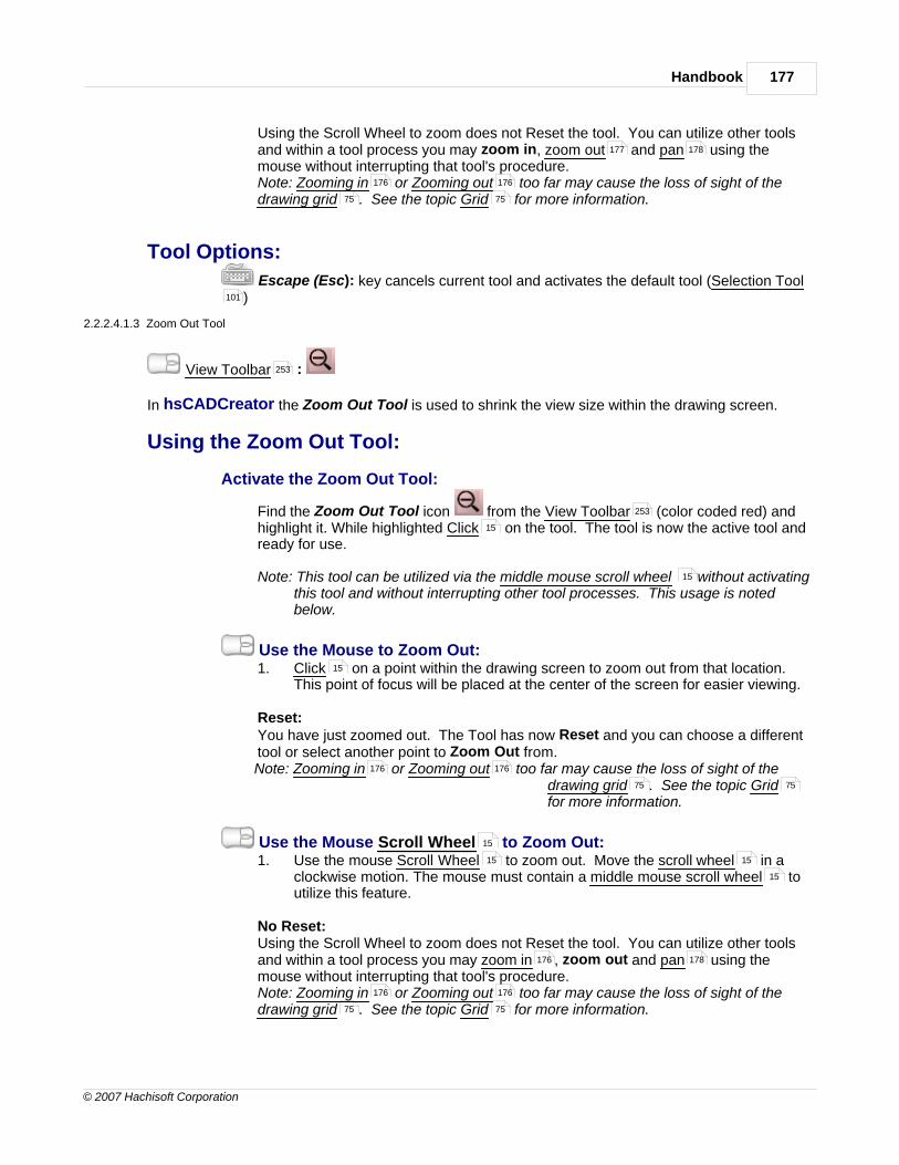
Handbook 177
© 2007 Hachisoft Corporation
Using the Scroll Wheel to zoom does not Reset the tool. You can utilize other toolsand within a tool process you may zoom in, zoom out and pan using themouse without interrupting that tool's procedure.Note: Zooming in or Zooming out too far may cause the loss of sight of thedrawing grid . See the topic Grid for more information.
Tool Options:
Escape (Esc): key cancels current tool and activates the default tool (Selection Tool)
2.2.2.4.1.3 Zoom Out Tool
View Toolbar :
In hsCADCreator the Zoom Out Tool is used to shrink the view size within the drawing screen.
Using the Zoom Out Tool:
Activate the Zoom Out Tool:
Find the Zoom Out Tool icon from the View Toolbar (color coded red) andhighlight it. While highlighted Click on the tool. The tool is now the active tool andready for use.
Note: This tool can be utilized via the middle mouse scroll wheel without activatingthis tool and without interrupting other tool processes. This usage is notedbelow.
Use the Mouse to Zoom Out:1. Click on a point within the drawing screen to zoom out from that location.
This point of focus will be placed at the center of the screen for easier viewing.
Reset:You have just zoomed out. The Tool has now Reset and you can choose a differenttool or select another point to Zoom Out from.Note: Zooming in or Zooming out too far may cause the loss of sight of the
drawing grid . See the topic Gridfor more information.
Use the Mouse Scroll Wheel to Zoom Out:1. Use the mouse Scroll Wheel to zoom out. Move the scroll wheel in a
clockwise motion. The mouse must contain a middle mouse scroll wheel toutilize this feature.
No Reset:Using the Scroll Wheel to zoom does not Reset the tool. You can utilize other toolsand within a tool process you may zoom in , zoom out and pan using themouse without interrupting that tool's procedure.Note: Zooming in or Zooming out too far may cause the loss of sight of thedrawing grid . See the topic Grid for more information.
177 178
176 176
75 75
101
253
253
15
15
15
176 176
75 75
15
15 15
15
176 178
176 176
75 75

hsCADCreator Help178
© 2007 Hachisoft Corporation
Tool Options:
Escape (Esc): key cancels current tool and activates the default tool (Selection Tool)
2.2.2.4.1.4 Zoom Extent Tool
View Toolbar :
In hsCADCreator the Zoom To Extents is used zoom in or out such that the entire drawing is visiblewithin the drawing screen.
Using the Zoom To Extents Tool:
Using the Zoom to Extents Tool:
Find the Zoom To Extents Tool icon from the View Toolbar (color codedred) and highlight it. While highlighted Click on the tool. The drawing screen willnow refresh and will display all of the drawing such that it will fit to the limits of thedrawing screen.
Note: This tool will not Activate. It is a one time tool. This means you can use thistool at any time and without interrupting other tool processes.
Also See: View Toolbar
2.2.2.4.2 Pan View Tool
View Toolbar :
In hsCADCreator the Pan View Tool is used to translate the entire drawing within the drawingscreen.
Using the Pan View Tool:
Activate the Pan View Tool:
Find one of the Pan View Tool icon from the View Toolbar (color coded red)and highlight it. While highlighted Click on the tool. The tool is now the active tooland ready for use.
Note: This tool can be utilized via the middle mouse button click without activatingthis tool and without the interruption other tool processes. This usage is notedbelow.
Use the Mouse to Pan the View:1. Click and hold the left mouse button on a point within the drawing screen.
While holding the button down move the mouse and translate the entiredrawing within the drawing screen to the desired location.
Reset:
101
253
253
15
253
253
253
15
15
15 15

Handbook 179
© 2007 Hachisoft Corporation
You have just performed a Pan of the View. The Tool has now Reset and you canchoose a different tool or perform another Pan View.Note: It is possible to pan the drawing to where you can no longer see any of thedrawing on the screen. If you cannot find the drawing use the Zoom to Extents toreset the view on the drawing.
Use the Middle Mouse Button to Pan the View:1. Click and hold the middle mouse button . While holding the button down
move the mouse and translate the entire drawing within the drawing screen tothe desired location. Note: you must have a middle mouse button to utilize thisfeature.
No Reset:Using the Middle Mouse button to Pan the View does not Reset the tool. You canutilize other tools and within a tool process you may zoom in, zoom out and pan
using the mouse without interrupting that tool's procedure.Note: It is possible to pan the drawing to where you can no longer see any of thedrawing on the screen. If you cannot find the drawing use the Zoom to Extents toreset the view on the drawing.
Tool Options:
Escape (Esc): key cancels current tool and activates the default tool (Selection Tool)
2.2.2.4.3 Rotate View Tools
View Toolbar :
In hsCADCreator, entities can be rotated around each axis in a 2D or 3D plane separately, or allthree simultaneously. The following tools facilitate viewing from different perspectives:
Using the Rotate View Tools:
Activate a Rotate View Tool:
Find one of the Rotate View Tool icons from the View Toolbar(color coded red) and highlight it. While highlighted Click on the tool. The tool isnow the active tool and ready for use.
Rotating the View:There are four different tools that will allow rotation of the view.
1. Rotate About Eye Vector Tool : The eye vector is that which approaches(or goes away from) the user's eye. This tool rotates entities about an axis in a circularmotion (similar to a pinwheel twirling on a wall).
2. Rotate About Vertical Vector Tool : This tool rotates entities around anup and down axis (similar to a tetherball circling an upright pole).
3. Rotate About Horizontal Vector Tool : This tool rotates entities around a
178
15
15 15
15
177
178
178
101
253
253
15
180
181
182

hsCADCreator Help180
© 2007 Hachisoft Corporation
side to side axis (similar to a gymnast rotating about a high bar).
4. Rotate View 3D Tool : This tool rotates entities about all three axessimultaneously (like a skydiver rolling and tumbling in a free fall--any rotationalmovement is possible).
Also See: View Toolbar
2.2.2.4.3.1 Rotate About Eye Vector Tool
View Toolbar :
In hsCADCreator, the Rotate About Eye Vector Tool facilitates rotational movement about an axiscoming to and going away from the eye of the user. (Note: depending upon the arbitrary assignment ofaxes this axis can either be X,Y, or Z or some other user designated vector.)
Using the Rotate About Eye Vector Tool:
Activate the Rotate About Eye Vector Tool:
Find the Rotate About Eye Vector icon from the View Toolbar (colorcoded red) and highlight it. While highlighted Click on the tool. The tool is now theactive tool and ready for use.
Use the Mouse to Rotate the View about the Eye Vector:1. Click and hold the left mouse button down. While holding the left button
down move the mouse around the center of the drawing screen. As you movethe mouse you will see the drawing rotate about the vector created from thecenter of the screen to the eye of the user or Eye Vector . Release the leftmouse button when the rotation is as desired.
Reset:You have just Rotated about the Eye Vector . The Tool has now Reset and you
can choose a different tool or rotateabout the Eye Vector again.
Note: It may be helpful to watch the UCS icon in the bottom left corner of thedrawing screen as you rotate the entity. Any axis that is moving toward you isrepresented with a solid line while an axis moving away is dotted.
183
253
253
15 253
15
15
15
15
15
15

Handbook 181
© 2007 Hachisoft Corporation
Tool Options:Horizontal vector mode changes the active tool to Rotate about Horizontal Vector Tool. Up vector mode changes the active tool to Rotate about Vertical Vector Tool Eye vector mode is the mode where the view is Rotated about Eye Vector Set target mode changes the active tool to Rotate about 3D Tool . Target point depicts the point about which the rotation will occur.
Escape (Esc): key cancels current tool and activates the default tool (Selection Tool)
2.2.2.4.3.2 Rotate About Vertical Vector Tool
View Toolbar :
In hsCADCreator, the Rotate About Vertical Vector Tool facilitates rotational movement aroundan up/down axis or vertical vector . (Note: depending upon the arbitrary assignment of axes this axiscan either be X,Y, Z, or some other user defined vector.)
Using the Rotate About Vertical Vector Tool:
Activate the Rotate About Vertical Vector Tool:
Find the Rotate About Vertical Vector icon from the View Toolbar (colorcoded red) and highlight it. While highlighted Click on the tool. The tool is now theactive tool and ready for use.
Use the Mouse to Rotate the View about the Vertical Vector:1. Click and hold the left mouse button down. While holding the left button
down move the mouse from right to left for a clockwise rotation about the vertical vector or left to right for counter-clockwise rotation about the verticalvector . As you move the mouse you will see the drawing rotate about thevertical vector . Release the left mouse button when the rotation is asdesired.
Reset:You have just Rotated about the Vertical Vector . The Tool has now Reset and
you can choose a different tool or rotateabout the vertical vector again.
182
181
183
101
253
15
253
15
15
15
15
15
15
15

hsCADCreator Help182
© 2007 Hachisoft Corporation
Note: It may be helpful to watch the UCS icon in the bottom left corner of thedrawing screen as you rotate the entity. Any axis that is moving toward you isrepresented with a solid line while an axis moving away is dotted.
Tool Options:Horizontal vector mode changes the active tool to Rotate about Horizontal Vector Tool. Up vector mode is the current mode for rotating the view about the vertical vector . Eye vector mode changes the active tool to Rotate about Eye Vector Tool .Set target mode changes the active tool to Rotate about 3D Tool . Target point depicts the point about which the rotation will occur.
Escape (Esc): key cancels current tool and activates the default tool (Selection Tool)
2.2.2.4.3.3 Rotate About Horizontal Vector Tool
View Toolbar :
In hsCADCreator, the Rotate About Horizontal Vector Tool facilitates the rotational movement ofan object about a side to side axis or Horizontal Vector . (Note: depending upon the arbitraryassignment of axes this axis can either be X,Y, or Z.)
Using the Rotate About Horizontal Vector Tool:
Activate the Rotate About Horizontal Vector Tool:
Find the Rotate About Horizontal Vector icon from the View Toolbar(color coded red) and highlight it. While highlighted Click on the tool. The tool isnow the active tool and ready for use.
Use the Mouse to Rotate the View about the Horizontal Vector:1. Click and hold the left mouse button down. While holding the left button
down move the mouse from top to bottom or bottom to top for rotation aboutthe Horizontal Vector . As you move the mouse you will see the drawingrotate about the Horizontal Vector . Release the left mouse button when therotation is as desired.
15
182
15
180
183
101
253
15
15 253
15
15
15
15

Handbook 183
© 2007 Hachisoft Corporation
Reset:You have just Rotated about the Horizontal Vector . The Tool has now Reset
and you can choose a different tool orrotate about the Horizontal Vectoragain.
Note: It may be helpful to watch the UCS icon in the bottom left corner of thedrawing screen as you rotate the entity. Any axis that is moving toward you isrepresented with a solid line while an axis moving away is dotted.
Tool Options:Horizontal vector mode is the current mode for rotating the view about the HorizontalVector . Up vector mode changes the active tool to Rotate about Vertical Vector Tool .Eye vector mode changes the active tool to Rotate about Eye Vector Tool .Set target mode changes the active tool to Rotate about 3D Tool . Target point depicts the point about which the rotation will occur.
Escape (Esc): key cancels current tool and activates the default tool (Selection Tool)
2.2.2.4.3.4 Rotate View 3D Tool
View Toolbar :
In hsCADCreator, the Rotate View 3D Tool facilitates the simultaneous rotational movement of anentity about all three axes with the origin at a user defined Target. (Note: depending upon the arbitraryassignment of axes a particular axis can be X,Y, or Z.)
Using the Rotate 3D Tool:
Activate the Rotate 3D Tool:
Find the Rotate 3D Tool icon from the View Toolbar (color coded red) andhighlight it. While highlighted Click on the tool. The tool is now the active tool andready for use.
Use the Mouse to Rotate the View in 3D about the Target:1. Click and hold the left mouse button down. While holding the left button
15
15
15
15
181
180
183
101
253
253
15
15

hsCADCreator Help184
© 2007 Hachisoft Corporation
down move the mouse in any direction. As you move the mouse you will seethe drawing rotate about the Target. Release the left mouse button when therotation is as desired.
Reset:You have just Rotated about the Target Point. The Tool has now Reset and you
can choose a different tool or rotateabout the Target Point again.
Note: It may be helpful to watch the UCS icon in the bottom left corner of thedrawing screen as you rotate the entity. Any axis that is moving toward you isrepresented with a solid line while an axis moving away is dotted.Note: It may be necessary to reset the rotation. To reset the rotation to a knownposition use the Preset View Snaps or to find the draw plane use the AlignView to UCS tool .
Tool Options:Horizontal vector mode changes the active tool to Rotate about Horizontal Vector Tool. Up vector mode changes the active tool to Rotate about Vertical Vector Tool .Eye vector mode changes the active tool to Rotate about Eye Vector Tool .Set target mode is the current mode for rotating the view about the Target in 3D.Target point depicts the point about which the rotation will occur.
Escape (Esc): key cancels current tool and activates the default tool (Selection Tool)
2.2.2.4.4 Divide Viewport Tool
View Toolbar :
In hsCADCreator the Divide Viewport Tool will custom divide the drawing screen into multipleviewports allowing you to create you own personal workspace with the views you need.
Using the Viewport Divide Tool:
Activate the Viewport Divide Tool:
Find the Viewport Divide Tool icon from the View Toolbar (color coded red)
15
187 15
211
182
181
180
101
253
253

Handbook 185
© 2007 Hachisoft Corporation
and highlight it. While highlighted Click on the tool. The tool is now the active tooland ready for use.
Use the Mouse Divide the Active Viewport:1. Move the mouse around and you will see a temporary cutting edge. When this
cutting edge is positioned as desired Click to divide the viewport at thatlocation. The tool will divide the active viewport either horizontally or verticallybased on the Split Type found in the Viewport Divide Settings.Note: The Viewport Divide tool will only divide the Active Viewport. To divide adifferent viewport you will need to select it before using this tool.
Reset:You have just divided this viewport. The Tool has now Reset and you can choose adifferent tool or divide the active viewport.
Divide the Active Viewport using the Property Tree:
To divide the viewport with more precise data do the following. Move the mousecursor beyond the right side of the drawing screen to the Tool Property Tree .
1. Select the Split Type from the "Split Type" Drop down Combo. The twochoices are Vertical and Horizontal.
2. Type in the Percentage data into the "Percentage" Scalar Data Field foundon the Tool Property Tree and press Enter to accept. In Horizontal Mode0% is at the bottom of the viewport and 100% is the top of the viewport. If in Vertical Mode 0% is located at the left and 100% is located at the right of theviewport.
Reset:You have just divided this viewport. The Tool has now Reset and you can choose adifferent tool or divide the active viewport.
Tool Options:Split Type is the type of cut the divide tool will make. The choices are Vertical orHorizontal.Percentage allows the user to specify splitting percentage of the active viewport.
Escape (Esc): key cancels current tool and activates the default tool (Selection Tool
15
15
260
77
260

hsCADCreator Help186
© 2007 Hachisoft Corporation
)
2.2.2.4.5 Pre-configured Viewport Tools
View Toolbar :
In hsCADCreator there are ten Pre-configured Viewport Tools from which to choose. Each offersa different drawing screen format to aid the user in viewing multiple projections of an entitysimultaneously. The following descriptions will aid you in choosing the best format for your drawingproject:
Using the Viewport Divide Tool:
Activate a Pre-Configured Viewport Tool:
Find one of the Pre-Configured Viewport Tool icons
from the View Toolbar (color coded red) and highlight it. Whilehighlighted Click on the tool. The tool has now changed the viewport settings foryour drawing.
Note: These tools will not Activate. They are one time tools. This means you canuse this tool at any time and without interrupting other tool processes to change theway you work within the drawing screen.
There are ten different Pre-Configured ways to display the drawing screen broken intoone or more viewports.
1. Single Viewport Tool : Drawing screen remains whole. Find the SingleViewport Tool icon <insert image> from the View Toolbar (color coded red)and maneuver the mouse to it. The cursor will highlight the icon and a small boxaround it. Right click . Ten pre-configured viewport tools will appear in a flyouttoolbar. The Single Viewport Tool is the first (default). Click . The drawingscreen viewport will remain whole.
2. 2 Vertical Viewports Tool : The drawing screen will be divided into twoequal viewports with a vertical divider. Select the second tool from the flyouttoolbar. Click.
3. 2 Horizontal Viewports Tool : The drawing screen will be divided into twoequal viewports with a horizontal divider. Select the third tool from the flyouttoolbar. Click.
4. 3 Right Viewports Tool : The drawing screen will be divided into two equalviewports vertically. The portion on the left will be further divided horizontallyinto two viewports (for a total of three). Select the fourth tool from the flyouttoolbar. Click.
5. 3 Left Viewports Tool : The drawing screen will be divided into two equalviewports vertically. The portion on the right will be further divided horizontallyinto two viewports (for a total of three). Select the fifth tool from the flyouttoolbar. Click.
101
253
253
15
15
15

Handbook 187
© 2007 Hachisoft Corporation
6. 3 Bottom Viewports Tool : The drawing screen will be divided into twoequal viewports horizontally. The upper portion will be further divided verticallyinto two viewports (for a total of three). Select the sixth tool from the flyouttoolbar. Click.
7. 3 Top Viewports Tool : The drawing screen will be divided into two equalviewports horizontally. The lower portion will be further divided vertically intotwo viewports (for a total of three). Select the seventh tool from the flyouttoolbar. Click.
8. 4 Even Viewports Tool : The drawing screen will be divided into four equalviewports (horizontally and vertically). Select the eighth tool from the flyouttoolbar. Click.
9. 4 Right Viewports Tool : The drawing screen will be divided into two equalviewports vertically. The portion on the left will be further divided horizontallyinto three equal viewports (for a total of four). Select the ninth tool from theflyout toolbar. Click.
10. 4 Left Viewports Tool : The drawing screen will be divided into two equalviewports vertically. The portion on the right will be further divided horizontallyinto three equal viewports (for a total of four). Select the tenth (or last tool) fromthe flyout toolbar. Click.
Also See: View ToolbarDivide Viewport Tool
2.2.2.5 Preset View Snap Tools
View Toolbar :
In hsCADCreator, Viewing the drawing in the best manner possible as well as snapping to commonviews within 3D space make working in this drawing environment much easier. The View Snap Toolsprovide a quick view manipulation toolbox for this very reason.
Using the Preset View Snap Tools:
Activate a Preset View Snap Tool:
Find one of the Preset View Snap Tool icons
from the View Toolbar (color coded red) and highlight it. Whilehighlighted Click on the tool. The tool is now the active tool and ready for use.This set of tools is part of a Flyout toolbar . To learn how to change tool selectionon a flyout toolbar see Flyout Toolbar .
253
184
253
253
15
81
81

hsCADCreator Help188
© 2007 Hachisoft Corporation
Use a Preset View Tool:There are six different Orthographic View Tools to use for quick view manipulation
1. Top View Tool
2. Bottom View Tool
3. Front (South) View Tool
4. Back (North) View Tool
5. Left Side (West) View Tool
6. Right Side (East) View Tool
There are four different Isometric View Tools to use for quick view manipulation.
1. Southwest View Tool
2. Southeast View Tool
3. Northeast View Tool
4. Northwest View Tool
Also See: View ToolbarFlyout Toolbar
2.2.2.5.1 Top View Tool
View Toolbar :
In hsCADCreator the Orthographic Projection Top View Tool facilitates viewing of an objectfrom above. This traditional plan view used in architecture and building engineering can be thought ofas a diagram of a room, a building, or a level (floor) of a building as if seen from a "bird's eye" view.
Using the Top View Tool:
Using the Top View Tool:
Find the Top View Tool icon from the View Toolbar (color coded red) andhighlight it. While highlighted Click on the tool. The drawing screen will nowrefresh and will display all of the drawing such that it is looking down in a "bird's eye"view of the 3D drawing.
Note: This tool will not Activate. It is a one time tool. This means you can use this
188
189
189
190
190
191
191
192
192
193
253
81
253
15
253
15

Handbook 189
© 2007 Hachisoft Corporation
tool at any time and without interrupting other tool processes.Note: This tools is part of a Flyout toolbar . To learn how to change tool selectionon a flyout toolbar see Flyout Toolbar .
Also See: View ToolbarFlyout toolbar
2.2.2.5.2 Bottom View Tool
View Toolbar :
In hsCADCreator the Orthographic Projection Bottom View Tool facilitates viewing of an objectfrom underneath. This nontraditional plan view is used primarily in instances where additional objectdetail (to a top view) is necessary.
Using the Bottom View Tool:
Using the Bottom View Tool:
Find the Bottom View Tool icon from the View Toolbar (color coded red)and highlight it. While highlighted Click on the tool. The drawing screen will nowrefresh and will display all of the drawing such that it is looking up at the underside of3D drawing.
Note: This tool will not Activate. It is a one time tool. This means you can use thistool at any time and without interrupting other tool processes.
Note: This tools is part of a Flyout toolbar . To learn how to change tool selectionon a flyout toolbar see Flyout Toolbar .
Also See: View ToolbarFlyout toolbar
2.2.2.5.3 Front (South) View Tool
View Toolbar :
In hsCADCreator the Orthographic Projection Front (South) View Tool facilitates viewing of anobject from its front side. This traditional orthographic view is used in architecture and buildingengineering and is the most critical elevation (i.e the above-ground-level front view of a building)
Using the Front (South) View Tool:
Using the Front (South) View Tool:
Find the Front (South) View Tool icon from the View Toolbar (color codedred) and highlight it. While highlighted Click on the tool. The drawing screen willnow refresh and will display all of the drawing such that it is looking at the front side ofa 3D drawing.
Note: This tool will not Activate. It is a one time tool. This means you can use thistool at any time and without interrupting other tool processes.
81
81
253
81
253
15
253
15
81
81
253
81
253
15
253
15

hsCADCreator Help190
© 2007 Hachisoft Corporation
Note: This tools is part of a Flyout toolbar . To learn how to change tool selectionon a flyout toolbar see Flyout Toolbar .
Also See: View ToolbarFlyout toolbar
2.2.2.5.4 Back (North) View Tool
View Toolbar :
In hsCADCreator the Orthographic Projection Back (North) View Tool facilitates viewing of anobject from behind. This traditional elevation (i.e. above ground level rear view of a building) used inarchitecture and building engineering is second only to the front elevation.
Using the Back (North) View Tool:
Using the Back (North) View Tool:
Find the Back (North) View Tool icon from the View Toolbar (color codedred) and highlight it. While highlighted Click on the tool. The drawing screen willnow refresh and will display all of the drawing such that it is looking at the back sideof a 3D drawing.
Note: This tool will not Activate. It is a one time tool. This means you can use thistool at any time and without interrupting other tool processes.
Note: This tools is part of a Flyout toolbar . To learn how to change tool selectionon a flyout toolbar see Flyout Toolbar .
Also See: View ToolbarFlyout toolbar
2.2.2.5.5 Left Side (West) View Tool
View Toolbar :
In hsCADCreator the Orthographic Projection Left Side (West) View Tool facilitates viewing ofan object from its left side. This nontraditional orthographic view, however, is important in architectureand building engineering (i.e the above-ground-level left side view of a building)
Using the Left Side (West) View Tool:
Using the Left Side (West) View Tool:
Find the Left Side (West) View Tool icon from the View Toolbar (colorcoded red) and highlight it. While highlighted Click on the tool. The drawingscreen will now refresh and will display all of the drawing such that it is looking at theLeft or West side of a 3D drawing.
81
81
253
81
253
15
253
15
81
81
253
81
253
15
253
15

Handbook 191
© 2007 Hachisoft Corporation
Note: This tool will not Activate. It is a one time tool. This means you can use thistool at any time and without interrupting other tool processes.
Note: This tools is part of a Flyout toolbar . To learn how to change tool selectionon a flyout toolbar see Flyout Toolbar .
Also See: View ToolbarFlyout toolbar
2.2.2.5.6 Right Side (East) View Tool
View Toolbar :
In hsCADCreator the Orthographic Projection Right Side (East) View Tool facilitates viewing ofan object from its right side. This traditional orthographic view is also used in architecture and buildingengineering (i.e the above-ground-level right side view of a building)
Using the Right Side (East) View Tool:
Using the Right Side (East) View Tool:
Find the Right Side (East) View Tool icon from the View Toolbar (colorcoded red) and highlight it. While highlighted Click on the tool. The drawingscreen will now refresh and will display all of the drawing such that it is looking at theRight or East side of a 3D drawing.
Note: This tool will not Activate. It is a one time tool. This means you can use thistool at any time and without interrupting other tool processes.
Note: This tools is part of a Flyout toolbar . To learn how to change tool selectionon a flyout toolbar see Flyout Toolbar .
Also See: View ToolbarFlyout toolbar
2.2.2.5.7 Southwest View Tool
View Toolbar :
In hsCADCreator the Isometric Projection Southwest View Tool facilitates viewing an objectfrom above, as well as from the front (south) and left (west) sides. Note: After a front view is arbitrarilyassigned, four different isometric projections can be viewed as the object is rotated clockwise.
Using the Southwest View Tool:
Using the Southwest View Tool:
81
81
253
81
253
15
253
15
81
81
253
81
253
15

hsCADCreator Help192
© 2007 Hachisoft Corporation
Find the Southwest View Tool icon from the View Toolbar (color coded red)and highlight it. While highlighted Click on the tool. The drawing screen will nowrefresh and will display all of the drawing such that it is looking down at the Front Leftor South West corner of a 3D drawing.
Note: This tool will not Activate. It is a one time tool. This means you can use thistool at any time and without interrupting other tool processes.
Note: This tools is part of a Flyout toolbar . To learn how to change tool selectionon a flyout toolbar see Flyout Toolbar .
Also See: View ToolbarFlyout toolbar
2.2.2.5.8 Southeast View Tool
View Toolbar :
In hsCADCreator the Isometric Projection Southeast View Tool facilitates viewing an objectfrom above, as well as from the front (south) and right (east) sides. Note: After a front view is arbitrarilyassigned, four different isometric projections can be viewed as the object is rotated clockwise.
Using the Southeast View Tool:
Using the Southeast View Tool:
Find the Southeast View Tool icon from the View Toolbar (color coded red)and highlight it. While highlighted Click on the tool. The drawing screen will nowrefresh and will display all of the drawing such that it is looking down at the FrontRight or South East corner of a 3D drawing.
Note: This tool will not Activate. It is a one time tool. This means you can use thistool at any time and without interrupting other tool processes.
Note: This tools is part of a Flyout toolbar . To learn how to change tool selectionon a flyout toolbar see Flyout Toolbar .
Also See: View ToolbarFlyout toolbar
2.2.2.5.9 Northeast View Tool
View Toolbar :
In hsCADCreator the Isometric Projection Northeast View Tool facilitates viewing an objectfrom above, as well as from the back (north) and right (east) sides. Note: After a front view is arbitrarilyassigned, four different isometric projections can be viewed as the object is rotated clockwise.
253
15
81
81
253
81
253
15
253
15
81
81
253
81
253
15

Handbook 193
© 2007 Hachisoft Corporation
Using the Northeast View Tool:
Using the Northeast View Tool:
Find the Northeast View Tool icon from the View Toolbar (color coded red)and highlight it. While highlighted Click on the tool. The drawing screen will nowrefresh and will display all of the drawing such that it is looking down at the BackRight or North East corner of a 3D drawing.
Note: This tool will not Activate. It is a one time tool. This means you can use thistool at any time and without interrupting other tool processes.
Note: This tools is part of a Flyout toolbar . To learn how to change tool selectionon a flyout toolbar see Flyout Toolbar .
Also See: View ToolbarFlyout toolbar
2.2.2.5.10 Northwest View Tool
View Toolbar :
In hsCADCreator the Isometric Projection Northwest View Tool facilitates viewing an objectfrom above, as well as from the back (north) and left (west) sides. Note: After a front view is arbitrarilyassigned, four different isometric projections can be viewed as the object is rotated clockwise.
Using the Northwest View Tool:
Using the Northwest View Tool:
Find the Northwest View Tool icon from the View Toolbar (color coded red)and highlight it. While highlighted Click on the tool. The drawing screen will nowrefresh and will display all of the drawing such that it is looking down at the Back Leftor North West corner of a 3D drawing.
Note: This tool will not Activate. It is a one time tool. This means you can use thistool at any time and without interrupting other tool processes.
Note: This tools is part of a Flyout toolbar . To learn how to change tool selectionon a flyout toolbar see Flyout Toolbar .
Also See: View ToolbarFlyout toolbar
2.2.2.6 Draw Plane Tools
In hsCADCreator, following UCS/Draw Plane Tools facilitate the creation of entities in three-dimensional space:
253
15
81
81
253
81
253
15
253
15
81
81
253
81

hsCADCreator Help194
© 2007 Hachisoft Corporation
1. Preset View Snaps : Allow access to six different planes to facilitate creation of three-dimensional drawings. The planes correspond to the six orthographic views: top, bottom, front,back, left side, and right side.
Snap UCS to Top View
Snap UCS to Bottom View
Snap UCS to Front (South) View
Snap UCS to Back (North) View
Snap UCS to Left (West) View
Snap UCS to Right (East) View
2. Rotate UCS/UCS/Draw Plane Tools :
Rotate UCS About X-axis Tool
Rotate UCS About Y-axis Tool
Rotate UCS About Z-axis Tool
Rotate UCS About Line Tool
3. Translate UCS/Draw Plane Tools :
Translate UCS Origin Along X-axis Tool
Translate UCS Origin Along Y-axis Tool
Translate UCS Origin Along Z-axis Tool
Translate UCS Origin To Point Tool
4. Align UCS to Current View Tool Aligns the User Coordinate System with whatevercurrent view the user has activated.
5. Align Current View to UCS Tool Aligns whatever current view the user has activatedwith the User Coordinate System.
6. Move UCS Origin to WCS Origin Tool Moves the User Coordinate System origin tocoincide with the World Coordinate System origin.
7. Align UCS Axis to WCS Axis Tool Aligns the User Coordinate System axis to theWorld Coordinate System axis.
8. Align UCS to Selected Entities Tool Aligns the User Coordinate System such that ifall selected entities are on same plane, the selected entities plane becomes X-Y plane of UCS.
195
195
196
197
197
197
198
198
199
201
202
203
205
206
207
208
209
210
211
211
212
212

Handbook 195
© 2007 Hachisoft Corporation
2.2.2.6.1 Preset UCS View Snaps
Drawplane Toolbar :
In hsCADCreator six Preset View Snaps are available to aid the user in creating three-dimensionaldrawing entities:
Using the Preset USC View Snap Tools:
Activate a Preset View Snap Tool:
Find one of the Preset USC view Snap Tool icons fromthe Drawplane Toolbar (color coded purple) and highlight it. While highlightedClick on the tool. The tool is now the active tool and ready for use. This set oftools is part of a Flyout toolbar .
Use a Preset View Tool:There are six different USC View snap tools to use for quick UCS manipulation
1. Snap UCS to Top View : Traditional overhead plane
2. Snap UCS to Bottom View : Underneath plane
3. Snap UCS to Front (South) View : Traditional front (side) plane
4. Snap UCS to Back (North) View : Back (side) plane
5. Snap UCS to Left (West) View : Left (side) plane
6. Snap UCS to Right (East) View : Traditional right (side) plane
Also See: Draw Plane ToolbarFlyout Toolbar
2.2.2.6.1.1 Snap UCS to Top View Tool
UCS Draw Plane Toolbar :
The Snap UCS to Top View Tool facilitates drawing on an overhead plane (i.e. floor plan, map, etc.)by changing the current UCS to align with overhead plane.
254
254
15
81
195
196
197
197
197
198
254
81
254
59
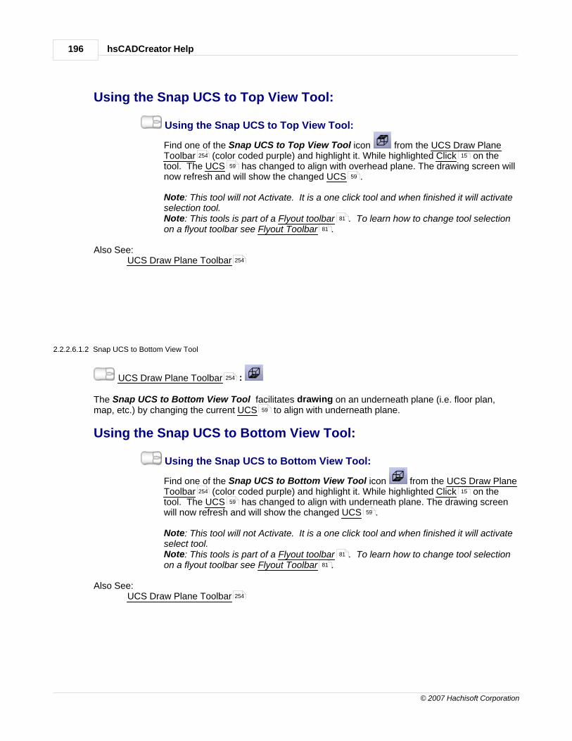
hsCADCreator Help196
© 2007 Hachisoft Corporation
Using the Snap UCS to Top View Tool:
Using the Snap UCS to Top View Tool:
Find one of the Snap UCS to Top View Tool icon from the UCS Draw PlaneToolbar (color coded purple) and highlight it. While highlighted Click on thetool. The UCS has changed to align with overhead plane. The drawing screen willnow refresh and will show the changed UCS .
Note: This tool will not Activate. It is a one click tool and when finished it will activateselection tool. Note: This tools is part of a Flyout toolbar . To learn how to change tool selectionon a flyout toolbar see Flyout Toolbar .
Also See: UCS Draw Plane Toolbar
2.2.2.6.1.2 Snap UCS to Bottom View Tool
UCS Draw Plane Toolbar :
The Snap UCS to Bottom View Tool facilitates drawing on an underneath plane (i.e. floor plan,map, etc.) by changing the current UCS to align with underneath plane.
Using the Snap UCS to Bottom View Tool:
Using the Snap UCS to Bottom View Tool:
Find one of the Snap UCS to Bottom View Tool icon from the UCS Draw PlaneToolbar (color coded purple) and highlight it. While highlighted Click on thetool. The UCS has changed to align with underneath plane. The drawing screenwill now refresh and will show the changed UCS .
Note: This tool will not Activate. It is a one click tool and when finished it will activateselect tool. Note: This tools is part of a Flyout toolbar . To learn how to change tool selectionon a flyout toolbar see Flyout Toolbar .
Also See: UCS Draw Plane Toolbar
254 15
59
59
81
81
254
254
59
254 15
59
59
81
81
254

Handbook 197
© 2007 Hachisoft Corporation
2.2.2.6.1.3 Snap UCS to Front (South) View Tool
UCS Draw Plane Toolbar :
The Snap UCS to Front (South) View Tool facilitates drawing on an front side plane by changingthe current UCS to align with front side plane.
Using the Snap UCS to Front (South) View Tool:
Using the Snap UCS to Front (South) View Tool:
Find one of the Snap UCS to Front (South) View Tool icon from the UCS DrawPlane Toolbar (color coded purple) and highlight it. While highlighted Click onthe tool. The UCS has changed to align with front side plane. The drawing screenwill now refresh and will show the changed UCS .
Note: This tool will not Activate. It is a one click tool and when finished it will activateselect tool. Note: This tools is part of a Flyout toolbar . To learn how to change tool selectionon a flyout toolbar see Flyout Toolbar .
Also See: UCS Draw Plane Toolbar
2.2.2.6.1.4 Snap UCS to Back (North) View Tool
UCS Draw Plane Toolbar :
The Snap UCS to Back (North) View Tool facilitates drawing on an back side plane by changingthe current UCS to align with back side plane.
Using the Snap UCS to Back (North) View Tool:
Using the Snap UCS to Back (North) View Tool:
Find one of the Snap UCS to Back (North) View Tool icon from the UCS DrawPlane Toolbar (color coded purple) and highlight it. While highlighted Click onthe tool. The UCS has changed to align with back side plane. The drawing screenwill now refresh and will show the changed UCS .
Note: This tool will not Activate. It is a one click tool and when finished it will activateselect tool. Note: This tools is part of a Flyout toolbar . To learn how to change tool selectionon a flyout toolbar see Flyout Toolbar .
Also See: UCS Draw Plane Toolbar
2.2.2.6.1.5 Snap UCS to Left (West) View Tool
UCS Draw Plane Toolbar :
254
59
254 15
59
59
81
81
254
254
59
254 15
59
59
81
81
254
254

hsCADCreator Help198
© 2007 Hachisoft Corporation
The Snap UCS to Left (West) View Tool facilitates drawing on an left side plane by changing thecurrent UCS to align with left side plane.
Using the Snap UCS to Left (West) View Tool:
Using the Snap UCS to Left (West) View Tool:
Find one of the Snap UCS to Left (West) View Tool icon from the UCS DrawPlane Toolbar (color coded purple) and highlight it. While highlighted Click onthe tool. The UCS has changed to align with left side plane. The drawing screenwill now refresh and will show the changed UCS .
Note: This tool will not Activate. It is a one click tool and when finished it will activateselect tool. Note: This tools is part of a Flyout toolbar . To learn how to change tool selectionon a flyout toolbar see Flyout Toolbar .
Also See: UCS Draw Plane Toolbar
2.2.2.6.1.6 Snap UCS to Right (East) View Tool
UCS Draw Plane Toolbar :
The Snap UCS to Right (East) View Tool facilitates drawing on an right side plane by changing thecurrent UCS to align with right side plane.
Using the Snap UCS to Right (East) View Tool:
Using the Snap UCS to Right (East) View Tool:
Find one of the Snap UCS to Right (East) View Tool icon from the UCS DrawPlane Toolbar (color coded purple) and highlight it. While highlighted Click onthe tool. The UCS has changed to align with right side plane. The drawing screenwill now refresh and will show the changed UCS .
Note: This tool will not Activate. It is a one click tool and when finished it will activateselect tool. Note: This tools is part of a Flyout toolbar . To learn how to change tool selectionon a flyout toolbar see Flyout Toolbar .
Also See: UCS Draw Plane Toolbar
2.2.2.6.2 Rotate UCS Tools
Drawplane Toolbar :
In hsCADCreator the Rotate UCS Tools facilitate the rotation of active UCS about co-ordinateaxis or about an arbitrary line. There are four tools available from which the user can choose:
59
254 15
59
59
81
81
254
254
59
254 15
59
59
81
81
254
254
59

Handbook 199
© 2007 Hachisoft Corporation
Using the Rotate USC Tools:
Activate a Rotate UCS Tool:
Find one of the Rotate UCS Tool icons from the DrawplaneToolbar (color coded purple) and highlight it. While highlighted Click on thetool. The tool is now the active tool and ready for use. This set of tools is part of a Flyout toolbar .
Use a Rotate UCS Tool:There are four different USC Rotation tools to for fast UCS manipulation. The toolsare listed below.
1. Rotate UCS About X-axis Tool
2. Rotate UCS About Y-axis Tool
3. Rotate UCS About Z-axis Tool
4. Rotate UCS About Line Tool
Also See: Draw Plane ToolbarFlyout Toolbar
2.2.2.6.2.1 Rotate UCS About X-axis Tool
UCS Toolbar :
The Rotate UCS About X-axis Tool facilitates rotation of active UCS about X-axis by specifiedangle.
Using the Rotate UCS About X-axis Tool:
Activate the Rotate UCS About X-axis Tool:
Find the Rotate UCS About X-axis Tool icon from the UCS Toolbar(color coded purple) and highlight it. While highlighted Click on the tool. The toolis now the active tool and ready for use.
Note: This tools is part of a Flyout toolbar . To learn how to change tool selectionon a flyout toolbar see Flyout Toolbar .
254 15
81
199
201
202
203
254
81
254
59
254
15
81
81

hsCADCreator Help200
© 2007 Hachisoft Corporation
Use the Mouse to Rotate UCS About X-axis:1. Click and hold the left mouse button down. While holding the left button
down move the mouse around the center of the drawing screen. As you movethe mouse you will see the UCS rotate about the X-axis. Release the leftmouse button when the rotation is as desired.
Reset:You have just Rotated UCS about X-axis. The Tool has now Reset and you canchoose a different tool or rotate UCS about X-axis again.
Use the keyboard to Rotate UCS About X-axis:1. Type in the Angle data into the "Included Angle" Scientific Data Field found
on the Tool Property Tree and press Enter to accept.
Reset:You have just Rotated UCS about X-axis. The Tool has now Reset and you canchoose a different tool or rotate UCS about X-axis again.
Tool Options:
Escape (Esc): key cancels current tool and activates the default tool (Selection Tool).
Space: key Resets this tool.
Also See: UCS ToolbarUCS
15
59
59
77
260
59
101
254
59

Handbook 201
© 2007 Hachisoft Corporation
2.2.2.6.2.2 Rotate UCS About Y-axis Tool
UCS Toolbar :
The Rotate UCS About Y-axis Tool facilitates rotation of active UCS about Y-axis by specifiedangle.
Using the Rotate UCS About Y-axis Tool:
Activate the Rotate UCS About Y-axis Tool:
Find the Rotate UCS About Y-axis Tool icon from the UCS Toolbar(color coded purple) and highlight it. While highlighted Click on the tool. The toolis now the active tool and ready for use.
Note: This tools is part of a Flyout toolbar . To learn how to change tool selectionon a flyout toolbar see Flyout Toolbar .
Use the Mouse to Rotate UCS About Y-axis:1. Click and hold the left mouse button down. While holding the left button
down move the mouse around the center of the drawing screen. As you movethe mouse you will see the UCS rotate about the Y-axis. Release the leftmouse button when the rotation is as desired.
Reset:You have just Rotated UCS about Y-axis. The Tool has now Reset and you canchoose a different tool or rotate UCS about Y-axis again.
Use the keyboard to Rotate UCS About Y-axis:1. Type in the Angle data into the "Included Angle" Scientific Data Field found
on the Tool Property Tree and press Enter to accept.
Reset:You have just Rotated UCS about Y-axis. The Tool has now Reset and you canchoose a different tool or rotate UCS about Y-axis again.
254
59
254
15
81
81
15
59
59
77
260
59

hsCADCreator Help202
© 2007 Hachisoft Corporation
Tool Options:
Escape (Esc): key cancels current tool and activates the default tool (Selection Tool).
Space: key Resets this tool.
Also See: UCS ToolbarUCS
2.2.2.6.2.3 Rotate UCS About Z-axis Tool
UCS Toolbar :
The Rotate UCS About Z-axis Tool facilitates rotation of active UCS about Z-axis by specifiedangle.
Using the Rotate UCS About Z-axis Tool:
Activate the Rotate UCS About Z-axis Tool:
Find the Rotate UCS About Z-axis Tool icon from the UCS Toolbar(color coded purple) and highlight it. While highlighted Click on the tool. The toolis now the active tool and ready for use.
Note: This tools is part of a Flyout toolbar . To learn how to change tool selectionon a flyout toolbar see Flyout Toolbar .
Use the Mouse to Rotate UCS About Z-axis:1. Click and hold the left mouse button down. While holding the left button
down move the mouse around the center of the drawing screen. As you movethe mouse you will see the UCS rotate about the Z-axis. Release the leftmouse button when the rotation is as desired.
Reset:You have just Rotated UCS about Z-axis. The Tool has now Reset and you canchoose a different tool or rotate UCS about Z-axis again.
101
254
59
254
59
254
15
81
81
15
59
59

Handbook 203
© 2007 Hachisoft Corporation
Use the keyboard to Rotate UCS About Z-axis:1. Type in the Angle data into the "Included Angle" Scientific Data Field found
on the Tool Property Tree and press Enter to accept.
Reset:You have just Rotated UCS about Z-axis. The Tool has now Reset and you canchoose a different tool or rotate UCS about Z-axis again.
Tool Options:
Escape (Esc): key cancels current tool and activates the default tool (Selection Tool).
Space: key Resets this tool.
Also See: UCS ToolbarUCS
2.2.2.6.2.4 Rotate UCS About Line Tool
UCS Toolbar :
The Rotate UCS About Line Tool facilitates rotation of active UCS about a given Line by specifiedangle.
Using the Rotate UCS About Line Tool:
Activate the Rotate UCS About Line Tool:
Find the Rotate UCS About Line Tool icon from the UCS Toolbar (colorcoded purple) and highlight it. While highlighted Click on the tool. The tool is now
77
260
59
101
254
59
254
59
254
15

hsCADCreator Help204
© 2007 Hachisoft Corporation
the active tool and ready for use.
Note: This tools is part of a Flyout toolbar . To learn how to change tool selectionon a flyout toolbar see Flyout Toolbar .
Use the Mouse to Rotate UCS About Line:1. Click anywhere on screen to specify the first point on rotate about line.2. Click anywhere on screen to specify the second point on rotate about line.3. Click and hold the left mouse button down. While holding the left button
down move the mouse around the center of the drawing screen. As you movethe mouse you will see the UCS rotate about the Z-axis. Release the leftmouse button when the rotation is as desired.
Reset:You have just Rotated UCS about Line. The Tool has now Reset and you canchoose a different tool or rotate UCS about Line again.
Use the keyboard to Rotate UCS About Line:1. Type in the Start Point point data into the "Point on Axis" 3D Point Property
Field found on the Tool Property Tree and press Enter to accept.2. Type in the End Point point data into the "Point on Axis" 3D Point Property
Field found on the Tool Property Tree and press Enter to accept.3. Type in the Angle data into the "Included Angle" Scientific Data Field
found on the Tool Property Tree and press Enter to accept.
Reset:You have just Rotated UCS about Line. The Tool has now Reset and you canchoose a different tool or rotate UCS about Line again.
Tool Options:
Escape (Esc): key cancels current tool and activates the default tool (Selection Tool).
Space: key Resets this tool.
81
81
15
15
15
59
59
77 260
77 260
77
260
59
101

Handbook 205
© 2007 Hachisoft Corporation
Also See: UCS ToolbarUCS
2.2.2.6.3 Translate UCS Tools
Drawplane Toolbar :
In hsCADCreator the Translate UCS Tools facilitate translation (movement) of all active UCS alongco-ordinate axis or to an arbitrary point. There are four tools available from which the user can choose:
Using the Translate USC Tools:
Activate a Rotate UCS Tool:
Find one of the Rotate UCS Tool icons from the DrawplaneToolbar (color coded purple) and highlight it. While highlighted Click on thetool. The tool is now the active tool and ready for use. This set of tools is part of a Flyout toolbar .
Use a Translate UCS Tool:There are four different USC Translation tools to for fast UCS manipulation. The toolsare listed below.
1. Translate UCS Origin Along X-axis Tool
2. Translate UCS Origin Along Y-axis Tool
3. Translate UCS Origin Along Z-axis Tool
4. Translate UCS Origin To Point Tool
Also See: Draw Plane ToolbarFlyout Toolbar
254
59
254
254 15
81
206
207
208
209
254
81

hsCADCreator Help206
© 2007 Hachisoft Corporation
2.2.2.6.3.1 Translate UCS Origin Along X-axis Tool
UCS Toolbar :
The Translate UCS Origin Along X-axis Tool facilitates translation/movement of active UCSorigin along X-axis by specified distance.
Using the Translate UCS Origin Along X-axis Tool:
Activate the Translate UCS Origin Along X-axis Tool:
Find the Translate UCS Origin Along X-axis Tool icon from the UCSToolbar (color coded purple) and highlight it. While highlighted Click on thetool. The tool is now the active tool and ready for use.
Note: This tools is part of a Flyout toolbar . To learn how to change tool selectionon a flyout toolbar see Flyout Toolbar .
Use the Mouse to Translate UCS Origin Along X-axis:1. Click anywhere on screen when desired distance is achieved for translation.
Reset:You have just Translated UCS along X-axis. The Tool has now Reset and you canchoose a different tool or translate UCS along X-axis again.
Use the keyboard to Translate UCS Origin Along X-axis:1. Type in the Distance data into the "Distance" Scientific Data Field found on
the Tool Property Tree and press Enter to accept.
Reset:You have just Translated UCS along X-axis. The Tool has now Reset and you canchoose a different tool or translate UCS along X-axis again.
254
59
254 15
81
81
15
59
77
260
59

Handbook 207
© 2007 Hachisoft Corporation
Tool Options:
Escape (Esc): key cancels current tool and activates the default tool (Selection Tool).
Space: key Resets this tool.
Also See: UCS ToolbarUCS
2.2.2.6.3.2 Translate UCS Origin Along Y-axis Tool
UCS Toolbar :
The Translate UCS Origin Along Y-axis Tool facilitates translation/movement of active UCSorigin along Y-axis by specified distance.
Using the Translate UCS Origin Along Y-axis Tool:
Activate the Translate UCS Origin Along Y-axis Tool:
Find the Translate UCS Origin Along Y-axis Tool icon from the UCSToolbar (color coded purple) and highlight it. While highlighted Click on thetool. The tool is now the active tool and ready for use.
Note: This tools is part of a Flyout toolbar . To learn how to change tool selectionon a flyout toolbar see Flyout Toolbar .
Use the Mouse to Translate UCS Origin Along Y-axis:1. Click anywhere on screen when desired distance is achieved for translation.
Reset:You have just Translated UCS along Y-axis. The Tool has now Reset and you canchoose a different tool or translate UCS along Y-axis again.
101
254
59
254
59
254 15
81
81
15
59

hsCADCreator Help208
© 2007 Hachisoft Corporation
Use the keyboard to Translate UCS Origin Along Y-axis:1. Type in the Distance data into the "Distance" Scientific Data Field found on
the Tool Property Tree and press Enter to accept.
Reset:You have just Translated UCS along Y-axis. The Tool has now Reset and you canchoose a different tool or translate UCS along Y-axis again.
Tool Options:
Escape (Esc): key cancels current tool and activates the default tool (Selection Tool).
Space: key Resets this tool.
Also See: UCS ToolbarUCS
2.2.2.6.3.3 Translate UCS Origin Along Z-axis Tool
UCS Toolbar :
The Translate UCS Origin Along Z-axis Tool facilitates translation/movement of active UCSorigin along Z-axis by specified distance.
Using the Translate UCS Origin Along Z-axis Tool:
Activate the Translate UCS Origin Along Z-axis Tool:
Find the Translate UCS Origin Along Z-axis Tool icon from the UCSToolbar (color coded purple) and highlight it. While highlighted Click on thetool. The tool is now the active tool and ready for use.
Note: This tools is part of a Flyout toolbar . To learn how to change tool selectionon a flyout toolbar see Flyout Toolbar .
Use the Mouse to Translate UCS Origin Along Z-axis:1. Click anywhere on screen when desired distance is achieved for translation.
Reset:You have just Translated UCS along Z-axis. The Tool has now Reset and you canchoose a different tool or translate UCS along Z-axis again.
77
260
59
101
254
59
254
59
254 15
81
81
15
59

Handbook 209
© 2007 Hachisoft Corporation
Use the keyboard to Translate UCS Origin Along Z-axis:1. Type in the Distance data into the "Distance" Scientific Data Field found on
the Tool Property Tree and press Enter to accept.
Reset:You have just Translated UCS along Z-axis. The Tool has now Reset and you canchoose a different tool or translate UCS along Z-axis again.
Tool Options:
Escape (Esc): key cancels current tool and activates the default tool (Selection Tool).
Space: key Resets this tool.
Also See: UCS ToolbarUCS
2.2.2.6.3.4 Translate UCS Origin to Point Tool
UCS Toolbar :
The Translate UCS Origin to Point Tool facilitates translation/movement of active UCS origin to aspecified point.
Using the Translate UCS Origin to Point Tool:
Activate the Translate UCS Origin to Point Tool:
Find the Translate UCS Origin to Point Tool icon from the UCS Toolbar (color coded purple) and highlight it. While highlighted Click on the tool. The
tool is now the active tool and ready for use.
Note: This tools is part of a Flyout toolbar . To learn how to change tool selection
77
260
59
101
254
59
254
59
254 15
81

hsCADCreator Help210
© 2007 Hachisoft Corporation
on a flyout toolbar see Flyout Toolbar .
Use the Mouse to Translate UCS Origin to Point:1. Click anywhere on screen where user wants to move active UCS origin.
Reset:You have just Translated UCS to Point. The Tool has now Reset and you canchoose a different tool or translate UCS to Point again.
Use the keyboard to Translate UCS Origin to Point:1. Type in the Origin Point point data into the "New Origin" 3D Point Property
Field found on the Tool Property Tree and press Enter to accept.
Reset:You have just Translated UCS to Point. The Tool has now Reset and you canchoose a different tool or translate UCS to Point again.
Tool Options:
Escape (Esc): key cancels current tool and activates the default tool (Selection Tool).
Space: key Resets this tool.
Also See: UCS ToolbarUCS
2.2.2.6.4 Align UCS to Current View Tool
UCS Draw Plane Toolbar :
The Align UCS to Current View Tool allows user to align active UCS to Current View such thatUCS X-Y plane is aligned with view's Horizontal and Vertical axis respectively.
81
15 59
59
77 260
59
101
254
59
254
59
59

Handbook 211
© 2007 Hachisoft Corporation
Using the Align UCS to Current View Tool:
Using the Align UCS to Current View Tool:
Find one of the Align UCS to Current View Tool icon from the UCS DrawPlane Toolbar (color coded purple) and highlight it. While highlighted Click onthe tool. The UCS has changed to align with view plane. The drawing screen willnow refresh and will show the changed UCS .
Note: This tool will not Activate. It is a one click tool and when finished it will activateselect tool.
Also See: UCS Draw Plane Toolbar
2.2.2.6.5 Align Current View to UCS Tool
UCS Draw Plane Toolbar :
The Align Current View to UCS Tool allows user to change Current View such that view's Horizontaland Vertical axis are aligned with UCS X-Y plane respectively.
Using the Align Current View to UCS Tool:
Using the Align Current View to UCS Tool:
Find one of the Align Current View to UCS Tool icon from the UCS DrawPlane Toolbar (color coded purple) and highlight it. While highlighted Click onthe tool. The Current View has changed to align with active UCS . The drawingscreen will now refresh and will show the changed view of the modelspace.
Note: This tool will not Activate. It is a one click tool and when finished it will activateselect tool.
Also See: UCS Draw Plane Toolbar
2.2.2.6.6 Move UCS Origin to WCS Origin Tool
UCS Draw Plane Toolbar :
The Move UCS Origin to WCS Origin Tool allows user to move active UCS origin point to WorldCoordinate System(WCS) Origin point (0, 0, 0).
Using the Move UCS Origin to WCS Origin Tool:
Using the Move UCS Origin to WCS Origin Tool:
Find one of the Move UCS Origin to WCS Origin Tool icon from the UCS DrawPlane Toolbar (color coded purple) and highlight it. While highlighted Click onthe tool. The drawing screen will now refresh and will show the changed UCS .
254 15
59
59
254
254
59
254 15
59
254
254
59
254 15
59

hsCADCreator Help212
© 2007 Hachisoft Corporation
Note: This tool will not Activate. It is a one click tool and when finished it will activateselect tool.
Also See: UCS Draw Plane Toolbar
2.2.2.6.7 Align UCS Axis to WCS Axis Tool
UCS Draw Plane Toolbar :
The Align UCS Axis to WCS Axis Tool allows user to align all axis of active UCS tocorresponding axis of World Coordinate System(WCS).
Using the Align UCS Axis to WCS Axis Tool:
Using the Align UCS Axis to WCS Axis Tool:
Find one of the Align UCS Axis to WCS Axis Tool icon from the UCS DrawPlane Toolbar (color coded purple) and highlight it. While highlighted Click onthe tool. The drawing screen will now refresh and will show the changed UCS .
Note: This tool will not Activate. It is a one click tool and when finished it will activateselect tool.
Also See: UCS Draw Plane Toolbar
2.2.2.6.8 Align UCS to Selected Entities
UCS Draw Plane Toolbar :
The Align UCS to Selected Entities Tool facilitates aligning of the User Coordinate System suchthat if all selected entities are on same plane, the selected entities plane becomes X-Y plane of UCS
.
Align UCS to Selected Entities:
Activate the Align UCS to Selected Entities Tool:
Find the Extend Entity Tool icon from the UCS Draw Plane Toolbar (color codedgreen) and highlight it. While highlighted Click on the tool. The tool is now the activetool and ready for use.
Note: If there is a selection prior to activating the Align UCS to Selected Entities Tool, theSelection Step will be skipped.
Select the Entity(ies) to define UCS Plane:This tool is a Stacked tool . If there is no selection prior to the activation of this toolthe Selection Tool will become active and allow the selection of the entities thatwill be used to define plane. 1. Select Entities to define plane.2. Press Enter to finish the Selection Tool . The tool tries to find the plane
254
254
59
254 15
59
254
254
59
254
15
15
101
101

Handbook 213
© 2007 Hachisoft Corporation
defined by selected entities. If all selected entities are on same plane then thetool aligns active UCS to this plane.
Reset:You have just changed active UCS . The tool has now Reset and you can eithercontinue with other tools or use the Align UCS to Selected Entities Tool again.
Tool Options:
Escape (Esc): key cancels current tool and activates the default tool (Selection Tool).
Space: key Resets this tool.
Also See:UCS Draw Plane Toolbar
2.2.2.7 Rendering Tools
In hsCADCreator, Eight Rendering Tools are available to the user to render drawings in differentways:
1. 2D Wireframe Tool
3D Wireframe Tool
Hidden Tool
Flat Shaded Tool
Gouraud Shaded Tool
Flat Shaded With Edges Tool
Gouraud Shaded With Edges Tool
8. Regenerate Tool
2.2.2.7.1 2D Wireframe Tool
Rendering Toolbar :
Using the 2D Wireframe Tool:
59
59
101
254
213
214
214
214
215
216
216
217
256
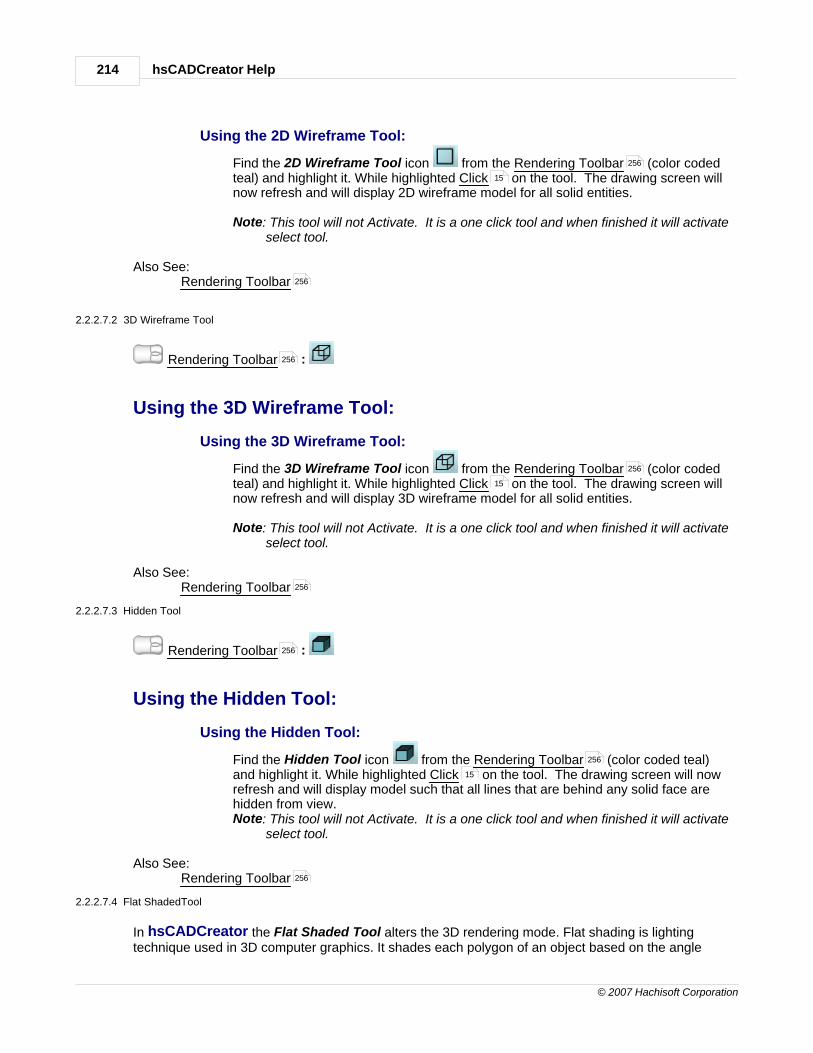
hsCADCreator Help214
© 2007 Hachisoft Corporation
Using the 2D Wireframe Tool:
Find the 2D Wireframe Tool icon from the Rendering Toolbar (color codedteal) and highlight it. While highlighted Click on the tool. The drawing screen willnow refresh and will display 2D wireframe model for all solid entities.
Note: This tool will not Activate. It is a one click tool and when finished it will activateselect tool.
Also See: Rendering Toolbar
2.2.2.7.2 3D Wireframe Tool
Rendering Toolbar :
Using the 3D Wireframe Tool:
Using the 3D Wireframe Tool:
Find the 3D Wireframe Tool icon from the Rendering Toolbar (color codedteal) and highlight it. While highlighted Click on the tool. The drawing screen willnow refresh and will display 3D wireframe model for all solid entities.
Note: This tool will not Activate. It is a one click tool and when finished it will activateselect tool.
Also See: Rendering Toolbar
2.2.2.7.3 Hidden Tool
Rendering Toolbar :
Using the Hidden Tool:
Using the Hidden Tool:
Find the Hidden Tool icon from the Rendering Toolbar (color coded teal)and highlight it. While highlighted Click on the tool. The drawing screen will nowrefresh and will display model such that all lines that are behind any solid face arehidden from view.Note: This tool will not Activate. It is a one click tool and when finished it will activate
select tool.
Also See: Rendering Toolbar
2.2.2.7.4 Flat ShadedTool
In hsCADCreator the Flat Shaded Tool alters the 3D rendering mode. Flat shading is lightingtechnique used in 3D computer graphics. It shades each polygon of an object based on the angle
256
15
256
256
256
15
256
256
256
15
256

Handbook 215
© 2007 Hachisoft Corporation
between the polygon's surface normal and the direction of the light source, their respective colors andthe intensity of the light source. It is usually used for high speed rendering where more advancedshading techniques are too computationally expensive.
The disadvantage of flat shading is that it gives low-polygon models a faceted look. Sometimes thislook can be advantageous though, such as in modeling boxy objects. Artists sometimes use flatshading to look at the polygons of a solid model they are creating. More advanced and realistic lightingand shading techniques include Gouraud shading and Phong shading.
This tool incorporates the flat shading technique but without visible object edge lines.
Rendering Toolbar :
Using the Flat Shaded Tool:
Using the Flat Shaded Tool:
Find the Flat Shaded Tool icon from the Rendering Toolbar (color codedteal) and highlight it. While highlighted Click on the tool. The drawing screen willnow refresh and will display modelspace entities with Flat Shaded mode.Note: This tool will not Activate. It is a one click tool and when finished it will activate
select tool.
Also See: Rendering Toolbar
2.2.2.7.5 Gouraud ShadedTool
In hsCADCreator the Gouraud Shaded Tool alters the 3D rendering mode. Gouraud shading is amethod used in computer graphics to simulate the differing effects of light and color across the surfaceof an object. In practice, Gouraud shading is used to achieve smooth lighting on low-polygon surfaceswithout the heavy computational requirements of calculating lighting for each pixel.
This tool incorporates the Gouraud shading technique but without visible object edge lines.
Rendering Toolbar :
Using the Gouraud Shaded Tool:
Using the Gouraud Shaded Tool:
Find the Gouraud Shaded Tool icon from the Rendering Toolbar (colorcoded teal) and highlight it. While highlighted Click on the tool. The drawingscreen will now refresh and will display modelspace entities with Gouraud Shadedmode.Note: This tool will not Activate. It is a one click tool and when finished it will activate
select tool.
Also See: Rendering Toolbar
256
256
15
256
256
256
15
256

hsCADCreator Help216
© 2007 Hachisoft Corporation
2.2.2.7.6 Flat Shaded With EdgesTool
In hsCADCreator the Flat Shaded With Edges Tool alters the 3D rendering mode. Flat shading islighting technique used in 3D computer graphics. It shades each polygon of an object based on theangle between the polygon's surface normal and the direction of the light source, their respectivecolors and the intensity of the light source. It is usually used for high speed rendering where moreadvanced shading techniques are too computationally expensive.
The disadvantage of flat shading is that it gives low-polygon models a faceted look. Sometimes thislook can be advantageous though, such as in modeling boxy objects. Artists sometimes use flatshading to look at the polygons of a solid model they are creating. More advanced and realistic lightingand shading techniques include Gouraud shading and Phong shading.
This tool incorporates the flat shading technique with visible object edge lines.
Rendering Toolbar :
Using the Flat Shaded With Edges Tool:
Using the Flat Shaded With Edges Tool:
Find the Flat Shaded With Edges Tool icon from the Rendering Toolbar(color coded teal) and highlight it. While highlighted Click on the tool. The drawingscreen will now refresh and will display modelspace entities with Flat Shaded WithEdges mode.Note: This tool will not Activate. It is a one click tool and when finished it will activate
select tool.
Also See: Rendering Toolbar
2.2.2.7.7 Gouraud Shaded With EdgesTool
In hsCADCreator the Gouraud Shaded With Edges Tool alters the 3D rendering mode. Gouraudshading is a method used in computer graphics to simulate the differing effects of light and coloracross the surface of an object. In practice, Gouraud shading is used to achieve smooth lighting onlow-polygon surfaces without the heavy computational requirements of calculating lighting for eachpixel.
This tool incorporates the Gouraud shading technique with visible object edge lines.
Rendering Toolbar :
Using the Gouraud Shaded With Edges Tool:
Using the Gouraud Shaded With Edges Tool:
Find the Gouraud Shaded With Edges Tool icon from the Rendering Toolbar (color coded teal) and highlight it. While highlighted Click on the tool. The
drawing screen will now refresh and will display modelspace entities with GouraudShaded With Edges mode.Note: This tool will not Activate. It is a one click tool and when finished it will activate
256
256
15
256
256
256 15

Handbook 217
© 2007 Hachisoft Corporation
select tool.
Also See: Rendering Toolbar
2.2.2.7.8 Regenerate Tool
In hsCADCreator the Regenerate Tool initiates a refreshment of the drawing in progress.
Rendering Toolbar :
Using the Regenerate Tool:
Using the Regenerate Tool:
Find the Regenerate Tool icon from the Rendering Toolbar (color codedteal) and highlight it. While highlighted Click on the tool. The drawing screen willnow redraw all the entities visible on the screen.Note: This tool will not Activate. It is a one click tool and when finished it will activate
select tool.
Also See: Rendering Toolbar
2.2.2.8 Library Tools
In hsCADCreator, Library Tools allow easy creation/edition/deletion of stored Objects . Thereare tools available to edit each type of Objects .
1. Manage Layers Tool
2. Quick Layer View Tool
3. Manage Blocks Tool
4. Manage Image Definitions Tool
5. Manage Colors Tool
6. Manage Text Styles Tool
7. Manage Linetypes Tool
8. Manage Multi Line Styles Tool
9. Manage Hatch Styles Tool
10. Manage Dimension Styles Tool
256
256
256
15
256
50
50
230
243
218
228
220
239
233
235
224
221

hsCADCreator Help218
© 2007 Hachisoft Corporation
11. Manage User Coordinate Systems Tool
12. Manage External References Tool
13. Manage Layouts Tool
Manage Plot Settings Tool
14. Manage Viewports Tool
15. Manage Named Views Tool
2.2.2.8.1 Manage Blocks Tool
Library Toolbar :
Manage Blocks Tool is used to edit/delete Block Definition Objects . See detail description fordifferent properties of Block Definition Objects .
Using the Manage Blocks Tool:
Find one of the Manage Blocks Tool icon from the Library Toolbar (color codedpeach) and highlight it. While highlighted Click on the tool. Manage Blocks Dialog willshow up and allows editing of Block Definition Objects . After performing requiredoperation in manage dialog, left click on OK button to save it to drawing. If Cancelbutton is left clicked , all the changes performed since opening of this manage dialogare undone .
241
223
232
238
242
236
257
61
61
257
15
61
15
15
89

Handbook 219
© 2007 Hachisoft Corporation
Select Block Definition:To select a block definition, Left click on one of the block names from the list displayedon left hand side of manage dialog.
View/Edit Block Definitions:To view properties of block definition , select a block definition as described in SelectBlock Definition. The Preview section will show small view of selected block definition. Allproperties for selected block definition are displayed on right hand side of manage dialog. Action Buttons available for selected block definition will be displayed under Actionssection below the block name list.
Add Block Definitions:To add block definitions to drawing, Block Definition Tool is used. The ManageBlock dialog does not allow to add new block definitions. Manage block dialog allowsediting of block definition's properties and deletion of block definitions.
Delete Block Definitions:To delete block definitions from drawing, select a block definition as described in Select
Block Definition section. Left click on delete button( ) under Actions section. The
selected block definition will be deleted. Delete button( ) becomes unavailable when
there is no block definition selected or selected block definition is hsCADCreator'sdefault created block definition.
Also See:
15
61
61 140
61
15

hsCADCreator Help220
© 2007 Hachisoft Corporation
Block Definition ObjectsLibrary Toolbar
2.2.2.8.2 Manage Colors Tool
Library Toolbar :
Manage Colors Tool is used to create/edit/delete Color Objects . See detail description for differentproperties of Color Objects .
Using the Manage Colors Tool:
Find one of the Manage Colors Tool icon from the Library Toolbar (color codedpeach) and highlight it. While highlighted Click on the tool. Manage Colors Dialog willshow up and allows editing of Color Objects . After performing required operation inmanage dialog, left click on OK button to save it to drawing. If Cancel button is leftclicked , all the changes performed since opening of this manage dialog are undone .
Select Color:To select a Color , Left click on one of the color names from the list displayed on lefthand side of manage dialog.
View/Edit Colors:To view properties of Color , select a color as described in Select Color. The Preview
61
257
257
51
51
257
15
51
15
15 89
51 15
51

Handbook 221
© 2007 Hachisoft Corporation
section will show the selected color as it will appear in drawing. All properties for selectedcolor are displayed on right hand side of manage dialog. Action Buttons available forselected color will be displayed under Actions section below the color names list.
Add Colors:
To add Color to drawing, Left click on add button ( ) under Actions. This opensa standard dialog to choose colors. After selecting required color click on OK and a newcolor is added to drawing's color library. By default the Name property of color object is setto R,G,B value for newly created color.
Delete Colors:To delete Color from drawing, select a color as described in Select Color section. Left
click on delete button( ) under Actions section. The selected color will be deleted.
Delete button( ) becomes unavailable when there is no color selected or selected color
is hsCADCreator's default created color.
Import Colors from a drawing:
To import Color from a drawing, Left click on import button( ) under Actionssection. This opens a standard file select dialog. After selecting required drawing file clickon OK and colors existing in selected drawing file will be added to current drawings colorlibrary.
Also See: Color ObjectsLibrary Toolbar
2.2.2.8.3 Manage Dimension Styles Tool
Library Toolbar :
Manage Dimension Styles Tool is used to create/edit/delete Dimension Style Objects . See detaildescription for different properties of Dimension Style Objects .
Using the Manage Dimension Styles Tool:
Find one of the Manage Dimension Styles Tool icon from the Library Toolbar(color coded peach) and highlight it. While highlighted Click on the tool. ManageDimension Styles Dialog will show up and allows editing of Dimension Style Objects .After performing required operation in manage dialog, left click on OK button to save itto drawing. If Cancel button is left clicked , all the changes performed since opening ofthis manage dialog are undone .
51 15
51
15
51 15
51
257
257
51
51
257
15
51
15
15
89
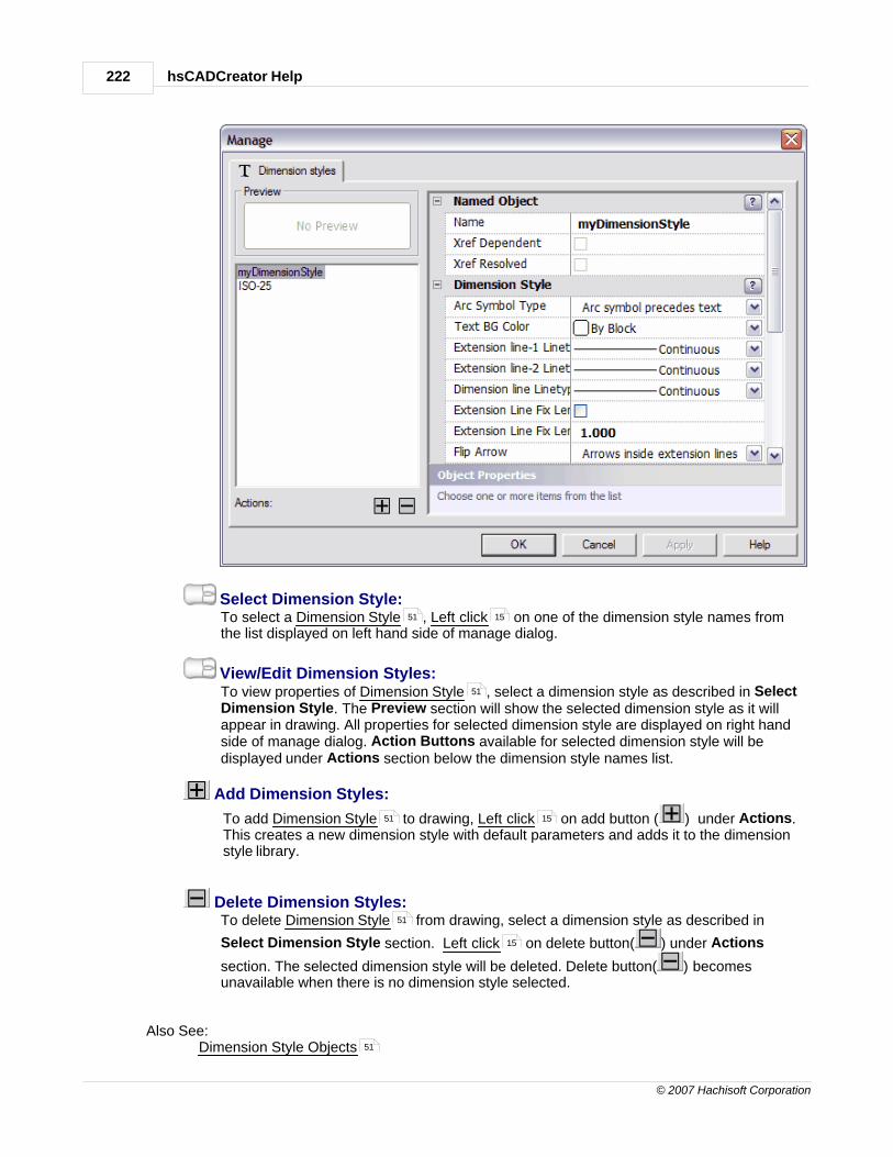
hsCADCreator Help222
© 2007 Hachisoft Corporation
Select Dimension Style:To select a Dimension Style , Left click on one of the dimension style names fromthe list displayed on left hand side of manage dialog.
View/Edit Dimension Styles:To view properties of Dimension Style , select a dimension style as described in SelectDimension Style. The Preview section will show the selected dimension style as it willappear in drawing. All properties for selected dimension style are displayed on right handside of manage dialog. Action Buttons available for selected dimension style will bedisplayed under Actions section below the dimension style names list.
Add Dimension Styles:
To add Dimension Style to drawing, Left click on add button ( ) under Actions.This creates a new dimension style with default parameters and adds it to the dimensionstyle library.
Delete Dimension Styles:To delete Dimension Style from drawing, select a dimension style as described in
Select Dimension Style section. Left click on delete button( ) under Actions
section. The selected dimension style will be deleted. Delete button( ) becomesunavailable when there is no dimension style selected.
Also See: Dimension Style Objects
51 15
51
51 15
51
15
51
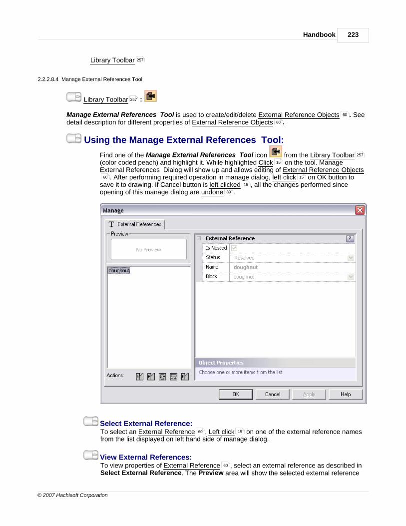
Handbook 223
© 2007 Hachisoft Corporation
Library Toolbar
2.2.2.8.4 Manage External References Tool
Library Toolbar :
Manage External References Tool is used to create/edit/delete External Reference Objects . Seedetail description for different properties of External Reference Objects .
Using the Manage External References Tool:
Find one of the Manage External References Tool icon from the Library Toolbar(color coded peach) and highlight it. While highlighted Click on the tool. ManageExternal References Dialog will show up and allows editing of External Reference Objects
. After performing required operation in manage dialog, left click on OK button tosave it to drawing. If Cancel button is left clicked , all the changes performed sinceopening of this manage dialog are undone .
Select External Reference:To select an External Reference , Left click on one of the external reference namesfrom the list displayed on left hand side of manage dialog.
View External References:To view properties of External Reference , select an external reference as described inSelect External Reference. The Preview area will show the selected external reference
257
257
60
60
257
15
60 15
15
89
60 15
60

hsCADCreator Help224
© 2007 Hachisoft Corporation
as it will appear in drawing. All properties for selected external reference are displayed onright hand side of manage dialog. Action Buttons available for selected external referencewill be displayed under Actions section below the external reference names list.
Attach/Add External References:
To attach/add External Reference to drawing, Left click on attach button ( ) under Actions. This opens a standard file select dialog. After selecting required drawingfile, click on OK. A new external reference with selected file name will be added drawing'slibrary.
Detach/Delete External References:To detach/delete External Reference from drawing, select an external reference as
described in Select External Reference. Left click on detach button( ) under
Actions section. The selected external reference will be deleted. Detach button( )becomes unavailable when there is no external reference selected or selected external
reference is hsCADCreator's default created external reference.
Load External References:To load/reload an existing External Reference , select a external reference as described
in Select External Reference. Left click on load button( ) under Actions section.The selected external reference will be loaded into drawing's memory.
Unload External References:To unload an existing External Reference from drawing's memory, select an external
reference as described in Select External Reference. Left click on unload button( )under Actions section. The selected external reference will be unloaded from drawing'smemory.
Bind External Reference as Block Definition :To bind an existing External Reference as Block Definition , select an external
reference as described in Select External Reference. Left click on bind button( )under Actions section. The selected external reference will be removed from externalreferences library and binded into current drawing as a block definition. Binding an externalreference as block definition creates a new block definition with external reference's name.Any block definition's within the external reference are also added as new block definitionsto current drawing with this naming convention: ExternalReferenceName$BlockNameInExternalReference.
Also See: External Reference ObjectsLibrary Toolbar
2.2.2.8.5 Manage Hatch Styles Tool
Library Toolbar :
Manage Hatch Pattern Tool is used to create/edit/delete Hatch Pattern Objects . See detaildescription for different properties of Hatch Pattern Objects .
Manage Hatch Styles:
51 15
51
15
51
15
51
15
61
51 61
15
60
257
257
61
61

Handbook 225
© 2007 Hachisoft Corporation
Activate a Manage Hatch Style Dialog:
Find the Manage Hatch Style Tool icons from the Library Toolbar (colorcoded peach) and highlight it. While highlighted Click on the tool. The tool willactivate the Manage Hatch Style dialog..
There are two different types of Hatch Styles. The two types are listed below. Visitthe links to get a more in depth look at the hatch styles.
1. Manage Hatch Gradient
2. Manage Hatch Pattern
2.2.2.8.5.1 Manage Hatch Gradient
Library Toolbar :
Manage Hatch Gradient Tool is used to create/edit/delete Hatch Gradient Objects . See detaildescription for different properties of Hatch Gradient Objects .
Using the Manage Hatch Gradient Tool:
Find one of the Manage Hatch Gradient Tool icon from the Library Toolbar (colorcoded peach) and highlight it. While highlighted Click on the tool. Manage dialog will bedisplayed. Click on the Hatch Gradients tab and it allows editing of Hatch GradientObjects . After performing required operation in manage dialog, left click on OKbutton to save it to drawing. If Cancel button is left clicked , all the changes performedsince opening of this manage dialog are undone .
257
15
225
227
257
60
60
257
15
15
60 15
15
89

hsCADCreator Help226
© 2007 Hachisoft Corporation
Select Hatch Gradient:To select a Hatch Gradient , Left click on one of the hatch gradient names from thelist displayed on left hand side of manage dialog.
View/Edit Hatch Gradients:To view properties of Hatch Gradient , select a hatch gradient as described in SelectHatch Gradient. The Preview section will show the selected hatch gradient as it willappear in drawing. All properties for selected hatch gradient are displayed on right handside of manage dialog. Action Buttons available for selected hatch gradient will bedisplayed under Actions section below the hatch gradient names list.
Add Hatch Gradients:
To add Hatch Gradient to drawing, Left click on add button ( ) under Actions.This adds a new hatch gradient to drawing's hatch gradient library. By default, the Nameproperty of hatch gradient object is set to "GradientNumber".
Delete Hatch Gradients:To delete Hatch Gradient from drawing, select a hatch gradient as described in Select
Hatch Gradient section. Left click on delete button( ) under Actions section. The
selected hatch gradient will be deleted. Delete button( ) becomes unavailable when
there is no hatch gradient selected or selected hatch gradient is hsCADCreator's defaultcreated hatch gradient.
Import Hatch Gradients from a gradient file (.GRA file):
51 15
51
51 15
51
15

Handbook 227
© 2007 Hachisoft Corporation
To import Hatch Gradient from a file, Left click on import button( ) under Actionssection. This opens a standard file select dialog. After selecting required gradient file clickon OK and gradients existing in selected file will be added to current drawings hatchgradient library.
Export Hatch Gradients to a gradient file (.GRA file):
To export Hatch Gradient to a file, Left click on export button( ) under Actionssection. This opens a standard file save dialog. After entering required gradient file name,click on OK and selected gradients information will be saved in .GRA file.
Also See: Hatch Gradient ObjectsLibrary Toolbar
2.2.2.8.5.2 Manage Hatch Pattern
Library Toolbar :
Manage Hatch Pattern Tool is used to create/edit/delete Hatch Pattern Objects . See detaildescription for different properties of Hatch Pattern Objects .
Using the Manage Hatch Pattern Tool:
Find one of the Manage Hatch Pattern Tool icon from the Library Toolbar (colorcoded peach) and highlight it. While highlighted Click on the tool. Manage Hatch Pattern Dialog will show up and allows editing of Hatch Pattern Objects . After performingrequired operation in manage dialog, left click on OK button to save it to drawing. IfCancel button is left clicked , all the changes performed since opening of this managedialog are undone .
51 15
51 15
60
257
257
61
61
257
15
61
15
15
89
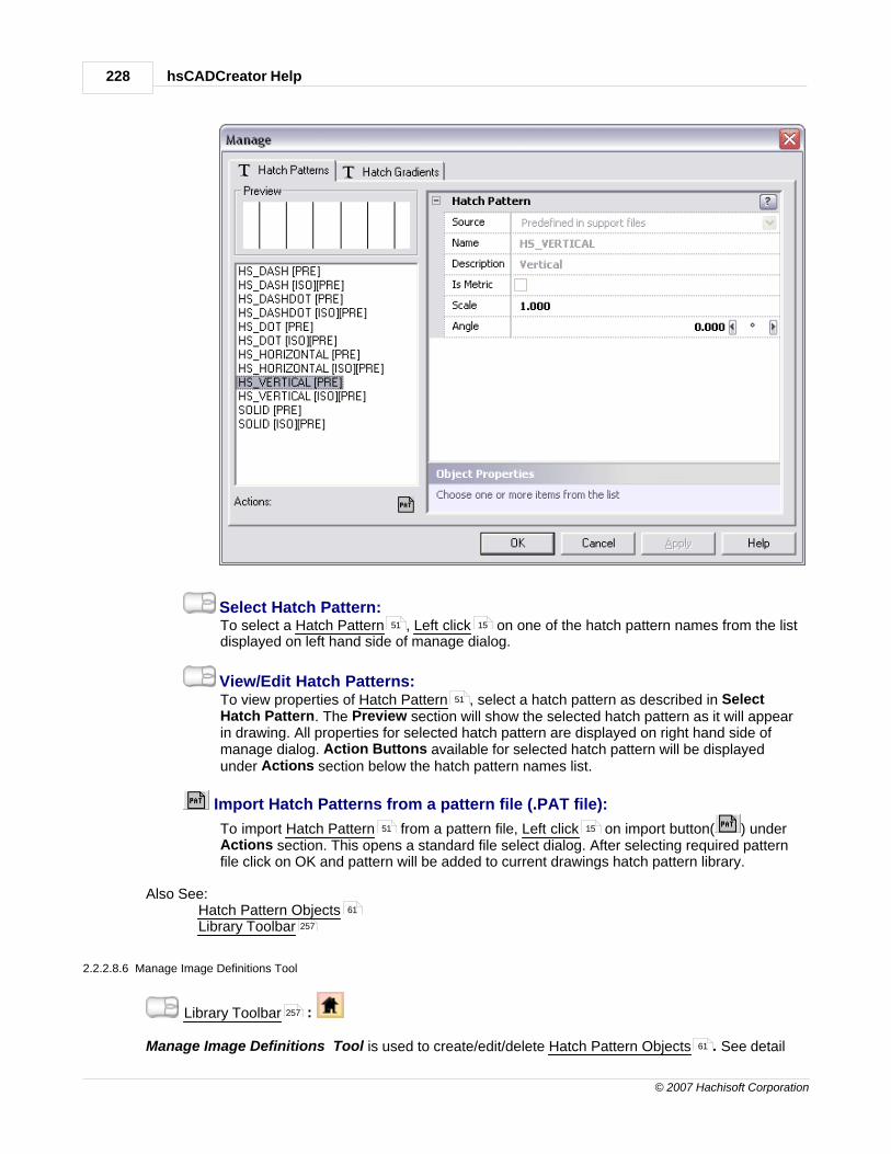
hsCADCreator Help228
© 2007 Hachisoft Corporation
Select Hatch Pattern:To select a Hatch Pattern , Left click on one of the hatch pattern names from the listdisplayed on left hand side of manage dialog.
View/Edit Hatch Patterns:To view properties of Hatch Pattern , select a hatch pattern as described in SelectHatch Pattern. The Preview section will show the selected hatch pattern as it will appearin drawing. All properties for selected hatch pattern are displayed on right hand side ofmanage dialog. Action Buttons available for selected hatch pattern will be displayedunder Actions section below the hatch pattern names list.
Import Hatch Patterns from a pattern file (.PAT file):
To import Hatch Pattern from a pattern file, Left click on import button( ) underActions section. This opens a standard file select dialog. After selecting required patternfile click on OK and pattern will be added to current drawings hatch pattern library.
Also See: Hatch Pattern ObjectsLibrary Toolbar
2.2.2.8.6 Manage Image Definitions Tool
Library Toolbar :
Manage Image Definitions Tool is used to create/edit/delete Hatch Pattern Objects . See detail
51 15
51
51 15
61
257
257
61

Handbook 229
© 2007 Hachisoft Corporation
description for different properties of Hatch Pattern Objects .
Using the Manage Image Definitions Tool:
Find one of the Manage Image Definitions Tool icon from the Library Toolbar(color coded peach) and highlight it. While highlighted Click on the tool. Manage ImageDefinitions Dialog will show up and allows editing of Hatch Pattern Objects . Afterperforming required operation in manage dialog, left click on OK button to save it todrawing. If Cancel button is left clicked , all the changes performed since opening of thismanage dialog are undone .
Select Image Definition:To select an Image Definition , Left click on one of the image definition names fromthe list displayed on left hand side of manage dialog.
View/Edit Image Definitions:To view properties of Image Definition , select an image definition as described inSelect Image Definition. The Preview section will show the selected image definition as itwill appear in drawing. All properties for selected image definition are displayed on righthand side of manage dialog. Action Buttons available for selected image definition will bedisplayed under Actions section below the image definition names list.
Add Image Definitions:
To add new Image Definition to drawing's library, Left click on add button ( ) under Actions. This opens a standard dialog to choose image files. After selecting
61
257
15
61
15
15
89
51 15
51
51 15

hsCADCreator Help230
© 2007 Hachisoft Corporation
required file, click on OK and a new image definition is added to drawing's image definitionlibrary. By default the Name property of image definition object is set to name of the sourcefile.
Delete Image Definitions:To delete Image Definition from drawing's library, select an image definition as
described in Select Image Definition. Left click on delete button( ) under Actions
section. The selected image definition will be deleted. Delete button( ) becomesunavailable when there is no image definition selected.
Also See: Hatch Pattern ObjectsLibrary Toolbar
2.2.2.8.7 Manage Layers Tool
Library Toolbar :
Manage Layers Tool is used to create/edit/delete Layer Objects . See detail description fordifferent properties of Layer Objects .
Using the Manage Layers Tool:
Find one of the Manage Layers Tool icon from the Library Toolbar (color codedpeach) and highlight it. While highlighted Click on the tool. Manage Layers Dialog willshow up and allows editing of Layer Objects . After performing required operation inmanage dialog, left click on OK button to save it to drawing. If Cancel button is leftclicked , all the changes performed since opening of this manage dialog are undone .
51
15
61 61
257
257
64
64
257
15
64
15
15 89

Handbook 231
© 2007 Hachisoft Corporation
Select Layer:To select a Layer , Left click on one of the layer names from the list displayed on lefthand side of manage dialog.
View/Edit Layers:To view properties of Layer , select a layer as described in Select Layer. All propertiesfor selected layer are displayed on right hand side of manage dialog. Action Buttonsavailable for selected layer will be displayed under Actions section below the layer nameslist.
Add Layers:
To add new Layer to drawing, Left click on add button ( ) under Actions. Thisadds a new layer to drawing's layer library. By default the Name property of layer object isset to LayerNumber.
Delete Layers:To delete Layer from drawing, select a layer as described in Select Layer. Left click
on delete button( ) under Actions section. The selected layer will be deleted. Delete
button( ) becomes unavailable when there is no layer selected or selected layer ishsCADCreator's default created layer.
Also See: Layer ObjectsLibrary Toolbar
51 15
51
51 15
51 15
64
257

hsCADCreator Help232
© 2007 Hachisoft Corporation
2.2.2.8.8 Manage Layouts Tool
Library Toolbar :
Manage Layouts Tool is used to create/edit/delete Layout Objects . See detail description fordifferent properties of Layout Objects .
Using the Manage Layouts Tool:
Find one of the Manage Layouts Tool icon from the Library Toolbar (color codedpeach) and highlight it. While highlighted Click on the tool. Manage Layouts Dialog willshow up and allows editing of Layout Objects . After performing required operation inmanage dialog, left click on OK button to save it to drawing. If Cancel button is leftclicked , all the changes performed since opening of this manage dialog are undone .
Select Layout:To select a Layout , Left click on one of the layout names from the list displayed onleft hand side of manage dialog.
View/Edit Layouts:To view properties of Layout , select a layout as described in Select Layout. ThePreview section will show the selected layout as it will appear in drawing. All properties forselected layout are displayed on right hand side of manage dialog. Action Buttonsavailable for selected layout will be displayed under Actions section below the layout
257
64
64
257
15
64
15
15 89
51 15
51

Handbook 233
© 2007 Hachisoft Corporation
names list.
Add Layouts:
To add new Layout to drawing, Left click on add button ( ) under Actions. Thisadds new layout to drawing's layout library. By default the Name property of layout object isset to LayoutNumber.
Delete Layouts:To delete Layout from drawing, select a layout as described in Select Layout. Left
click on delete button( ) under Actions section. The selected layout will be deleted.
Delete button( ) becomes unavailable when there is no layout selected or selected
layout is hsCADCreator's default created layout.
Import Layouts from print settings:
To import Layout from a print settings, Left click on import button( ) underActions section. This opens an object selection dialog. After selecting required printsettings click on OK and new layout will be imported into drawings layout library.
Also See: Layout ObjectsLibrary Toolbar
2.2.2.8.9 Manage Linetypes Tool
Library Toolbar :
Manage Linetypes Tool is used to create/edit/delete Linetypes Objects . See detail description fordifferent properties of Linetypes Objects .
Using the Manage Linetypes Tool:
Find one of the Manage Linetypes Tool icon from the Library Toolbar (colorcoded peach) and highlight it. While highlighted Click on the tool. Manage LinetypesDialog will show up and allows editing of Linetypes Objects . After performing requiredoperation in manage dialog, left click on OK button to save it to drawing. If Cancelbutton is left clicked , all the changes performed since opening of this manage dialogare undone .
51 15
51
15
51 15
64
257
257
66
66
257
15
66
15
15
89

hsCADCreator Help234
© 2007 Hachisoft Corporation
Select Linetype:To select a Linetype , Left click on one of the linetype names from the list displayedon left hand side of manage dialog.
View/Edit Linetypes:To view properties of Linetype , select a linetype as described in Select Linetype. ThePreview section will show the selected linetype as it will appear in drawing. All propertiesfor selected linetype are displayed on right hand side of manage dialog. Action Buttonsavailable for selected linetype will be displayed under Actions section below the linetypenames list.
Add Linetypes:
To add Linetype to drawing, Left click on add button ( ) under Actions. Thisadds a new linetype to drawing's linetype library. By default the Name property of linetypeobject is set to Line TypeNumber.
Delete Linetypes:To delete Linetype from drawing, select a linetype as described in Select Linetype
section. Left click on delete button( ) under Actions section. The selected linetype
will be deleted. Delete button( ) becomes unavailable when there is no linetype selected
or selected linetype is hsCADCreator's default created linetype.
Import Linetypes from a linetype file (.LIN file):
To import Linetype from a linetype file, Left click on import button( ) under
51 15
51
51 15
51
15
51 15
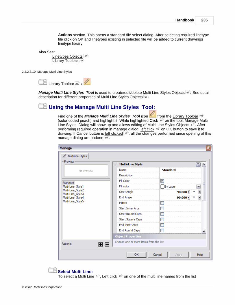
Handbook 235
© 2007 Hachisoft Corporation
Actions section. This opens a standard file select dialog. After selecting required linetypefile click on OK and linetypes existing in selected file will be added to current drawingslinetype library.
Also See: Linetypes ObjectsLibrary Toolbar
2.2.2.8.10 Manage Multi Line Styles
Library Toolbar :
Manage Multi Line Styles Tool is used to create/edit/delete Multi Line Styles Objects . See detaildescription for different properties of Multi Line Styles Objects .
Using the Manage Multi Line Styles Tool:
Find one of the Manage Multi Line Styles Tool icon from the Library Toolbar(color coded peach) and highlight it. While highlighted Click on the tool. Manage MultiLine Styles Dialog will show up and allows editing of Multi Line Styles Objects . Afterperforming required operation in manage dialog, left click on OK button to save it todrawing. If Cancel button is left clicked , all the changes performed since opening of thismanage dialog are undone .
Select Multi Line:To select a Multi Line , Left click on one of the multi line names from the list
66
257
257
67
67
257
15
67
15
15
89
51 15

hsCADCreator Help236
© 2007 Hachisoft Corporation
displayed on left hand side of manage dialog.
View Multi Lines:To view properties of Multi Line , select a multi line as described in Select Multi Line.The Preview section will show the selected multi line as it will appear in drawing. Allproperties for selected multi line are displayed on right hand side of manage dialog. ActionButtons available for selected multi line will be displayed under Actions section below themulti line names list.
Add Multi Lines:
To add Multi Line to drawing, Left click on add button ( ) under Actions. Thisadds a new multi line to drawing's multi line library. By default the Name property of multiline object is set to Multi-Line_StyleNumber.
Delete Multi Lines:To delete Multi Line from drawing, select a multi line as described in Select Multi Line
section. Left click on delete button( ) under Actions section. The selected multi line
will be deleted. Delete button( ) becomes unavailable when there is no multi line
selected or selected multi line is hsCADCreator's default created multi line.
Also See: Multi Line Styles ObjectsLibrary Toolbar
2.2.2.8.11 Manage Named Views Tool
Library Toolbar :
Manage Named Views Tool is used to create/edit/delete View Objects . See detail description fordifferent properties of View Objects .
Using the Manage Named Views Tool:
Find one of the Manage Named Views Tool icon from the Library Toolbar (colorcoded peach) and highlight it. While highlighted Click on the tool. Manage NamedViews Dialog will show up and allows editing of View Objects . After performing requiredoperation in manage dialog, left click on OK button to save it to drawing. If Cancelbutton is left clicked , all the changes performed since opening of this manage dialogare undone .
51
51 15
51
15
67
257
257
70
70
257
15
70
15
15
89

Handbook 237
© 2007 Hachisoft Corporation
Select View:To select a View , Left click on one of the view names from the list displayed on lefthand side of manage dialog.
View Views:To view properties of View , select a view as described in Select View section. ThePreview section will show the selected view as it will appear in drawing. All properties forselected view are displayed on right hand side of manage dialog. Action Buttons availablefor selected view will be displayed under Actions section below the view names list.
Add Views:
To add new View to drawing, Left click on add button ( ) under Actions. Thisadds a new view to drawing's view library. By default the Name property of view object isset to ViewNumber.
Delete Views:To delete View from drawing, select a view as described in Select View section. Left
click on delete button( ) under Actions section. The selected view will be deleted.
Delete button( ) becomes unavailable when there is no view selected.
Import/Add active view from drawing:
To add/import View from current drawing, Left click on add current button( )under Actions section. This creates a new view from currently active view in workingdrawing and adds it to drawing's library.
51 15
51
51 15
51
15
51 15

hsCADCreator Help238
© 2007 Hachisoft Corporation
Set view active in current drawing:To set active View in current drawing, select a view as described in Select View. Left
click on set active button( ) under Actions section. This will make currently selectedview active in working drawing.
Also See: View ObjectsLibrary Toolbar
2.2.2.8.12 Manage Plot Settings Tool
Library Toolbar :
Manage Plot Settings Tool is used to create/edit/delete Plot Setting Objects . See detaildescription for different properties of Plot Setting Objects .
Using the Manage Plot Settings Tool:
Find one of the Manage Plot Settings Tool icon from the Library Toolbar (colorcoded peach) and highlight it. While highlighted Click on the tool. Manage Plot SettingsDialog will show up and allows editing of Plot Setting Objects . After performing requiredoperation in manage dialog, left click on OK button to save it to drawing. If Cancelbutton is left clicked , all the changes performed since opening of this manage dialogare undone .
51
15
70
257
257
68
68
257
15
68
15
15
89

Handbook 239
© 2007 Hachisoft Corporation
Select Plot Settings:To select a Plot Settings , Left click on one of the plot settings names from the listdisplayed on left hand side of manage dialog.
View Plot Settings:To view properties of Plot Settings , select a plot settings as described in Select PlotSettings section. The Preview section will show the selected plot settings as it will appearin drawing. All properties for selected plot settings are displayed on right hand side ofmanage dialog. Action Buttons available for selected plot settings will be displayed underActions section below the plot settings names list.
Add Plot Settings:
To add Plot Settings to drawing, Left click on add button ( ) under Actions. Thisadds a new plot settings to drawing's plot settings library. By default the Name property ofplot settings object is set to Plot SettingsNumber.
Delete Plot Settings:To delete Plot Settings from drawing, select a plot settings as described in Select Plot
Settings section. Left click on delete button( ) under Actions section. The selected
plot settings will be deleted. Delete button( ) becomes unavailable when there is no plot
settings selected or selected plot settings is hsCADCreator's default created plotsettings.
Import Plot Settings from a drawing:
To import Plot Settings from an existing layout , Left click on import button( )under Actions section. This opens an object selection dialog. After selecting requiredlayout click on OK and plot settings from selected layout will be added to current drawingsplot settings library.
Also See: Plot Setting ObjectsLibrary Toolbar
2.2.2.8.13 Manage Text Styles Tool
Library Toolbar :
Manage Text Styles Tool is used to create/edit/delete Text Style Objects . See detail descriptionfor different properties of Text Style Objects .
Using the Manage Text Styles Tool:
Find one of the Manage Text Styles Tool icon from the Library Toolbar (colorcoded peach) and highlight it. While highlighted Click on the tool. Manage Text StylesDialog will show up and allows editing of Text Style Objects . After performing requiredoperation in manage dialog, left click on OK button to save it to drawing. If Cancelbutton is left clicked , all the changes performed since opening of this manage dialogare undone .
51 15
51
51 15
51
15
51 64 15
68
257
257
69
69
257
15
69
15
15
89

hsCADCreator Help240
© 2007 Hachisoft Corporation
Select Text Style:To select a Text Style , Left click on one of the text style names from the listdisplayed on left hand side of manage dialog.
View Text Styles:To view properties of Text Style , select a text style as described in Select Text Stylesection. The Preview section will show the selected text style as it will appear in drawing.All properties for selected text style are displayed on right hand side of manage dialog. Action Buttons available for selected text style will be displayed under Actions sectionbelow the text style names list.
Add Text Styles:
To add Text Style to drawing, Left click on add button ( ) under Actions. Thisadds a new text style to drawing's text style library. By default the Name property of textstyle object is set to TextStyleNumber.
Delete Text Styles:To delete Text Style from drawing, select a text style as described in Select Text Style
section. Left click on delete button( ) under Actions section. The selected text style
will be deleted. Delete button( ) becomes unavailable when there is no text style
selected or selected text style is hsCADCreator's default created text style.
Import Text Styles from a font file (.TTF file):
To import Text Style from a font file, Left click on import button( ) under Actions
51 15
51
51 15
51
15
51 15

Handbook 241
© 2007 Hachisoft Corporation
section. This opens a standard file select dialog. After selecting required font file click onOK and text styles existing in selected font file will be displayed in object selection dialog.Select required text styles and click on Import. Selected text styles will be added to currentdrawings text style library.
Also See: Text Style ObjectsLibrary Toolbar
2.2.2.8.14 Manage User Coordinate Systems Tool
Library Toolbar :
Manage User Coordinate Systems Tool is used to create/edit/delete User Coordinate SystemObjects . See detail description for different properties of User Coordinate System Objects .
Using the Manage User Coordinate Systems Tool:
Find one of the Manage User Coordinate Systems Tool icon from the LibraryToolbar (color coded peach) and highlight it. While highlighted Click on the tool.Manage User Coordinate Systems Dialog will show up and allows editing of UserCoordinate System Objects . After performing required operation in manage dialog, leftclick on OK button to save it to drawing. If Cancel button is left clicked , all thechanges performed since opening of this manage dialog are undone .
Select User Coordinate System:To select a User Coordinate System , Left click on one of the user coordinate
69
257
257
59 59
257 15
59
15 15
89
51 15
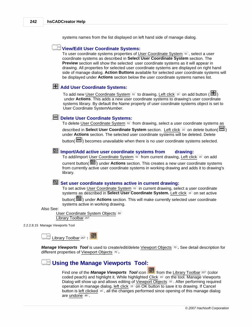
hsCADCreator Help242
© 2007 Hachisoft Corporation
systems names from the list displayed on left hand side of manage dialog.
View/Edit User Coordinate Systems:To user coordinate systems properties of User Coordinate System , select a usercoordinate systems as described in Select User Coordinate System section. ThePreview section will show the selected user coordinate systems as it will appear indrawing. All properties for selected user coordinate systems are displayed on right handside of manage dialog. Action Buttons available for selected user coordinate systems willbe displayed under Actions section below the user coordinate systems names list.
Add User Coordinate Systems:
To add new User Coordinate System to drawing, Left click on add button ( ) under Actions. This adds a new user coordinate systems to drawing's user coordinatesystems library. By default the Name property of user coordinate systems object is set toUser Coordinate SystemNumber.
Delete User Coordinate Systems:To delete User Coordinate System from drawing, select a user coordinate systems as
described in Select User Coordinate System section. Left click on delete button( )under Actions section. The selected user coordinate systems will be deleted. Delete
button( ) becomes unavailable when there is no user coordinate systems selected.
Import/Add active user coordinate systems from drawing:To add/import User Coordinate System from current drawing, Left click on add
current button( ) under Actions section. This creates a new user coordinate systemsfrom currently active user coordinate systems in working drawing and adds it to drawing'slibrary.
Set user coordinate systems active in current drawing:To set active User Coordinate System in current drawing, select a user coordinatesystems as described in Select User Coordinate System. Left click on set active
button( ) under Actions section. This will make currently selected user coordinatesystems active in working drawing.
Also See: User Coordinate System ObjectsLibrary Toolbar
2.2.2.8.15 Manage Viewports Tool
Library Toolbar :
Manage Viewports Tool is used to create/edit/delete Viewport Objects . See detail description fordifferent properties of Viewport Objects .
Using the Manage Viewports Tool:
Find one of the Manage Viewports Tool icon from the Library Toolbar (colorcoded peach) and highlight it. While highlighted Click on the tool. Manage ViewportsDialog will show up and allows editing of Viewport Objects . After performing requiredoperation in manage dialog, left click on OK button to save it to drawing. If Cancelbutton is left clicked , all the changes performed since opening of this manage dialogare undone .
51
51 15
51
15
51 15
51
15
59
257
257
70
70
257
15
70
15
15
89

Handbook 243
© 2007 Hachisoft Corporation
Select Model Viewport:To select a Model Viewport , Left click on one of the model viewport names from thelist displayed on left hand side of manage dialog.
View Model Viewports:To view properties of Model Viewport , select a model viewport as described in SelectModel Viewport section. The Preview section will show the selected model viewport as itwill appear in drawing. All properties for selected model viewport are displayed on righthand side of manage dialog.
Also See: Viewport ObjectsLibrary Toolbar
2.2.2.8.16 Quick Layer View Tool
Library Toolbar :
Quick Layer View Tool is used to create/edit/delete Layer Objects . See detail description fordifferent properties of Layer Objects .
Using the Quick Layer View Tool:
Find one of the Quick Layer View Tool icon from the Library Toolbar (color coded
51 15
51
70
257
257
64
64
257

hsCADCreator Help244
© 2007 Hachisoft Corporation
peach) and highlight it. While highlighted Click on the tool. Quick Layer View Dialog willshow up and allows quick turn on/off, freeze/thaw Layer Objects .
To turn ON/OFF any layer:Click on the "light-bulb" icon infront of the layer name. Depending on drawing's size, it
may take longer to reflect changes in drawing.To FREEZE/THAW any layer:
Click on the "Sun/Snow" icon infront of the layer name. Depending on drawing's size,it may take longer to reflect changes in drawing.
To Lock/Unlock any layer:Click on the "Lock" icon infront of the layer name. Depending on drawing's size, it
may take longer to reflect changes in drawing.To include/exclude a layer in printing:
Click on the "Printer" icon infront of the layer name. Depending on drawing's size, itmay take longer to reflect changes in drawing.
To edit any other properties, click on "Manage Layers..." button to access detailed layerproperties dialog.
Also See: Layer ObjectsLibrary Toolbar
2.2.2.9 Measure Tools
In hsCADCreator, Measure Tools allow easy measurement of length and area. There are twodifferent tools for measuring length and area.
1. Measure Distance Tool
15
64
64
257
245

Handbook 245
© 2007 Hachisoft Corporation
2. Measure Area Tool
3. Measure Angle Tool
2.2.2.9.1 Measure Distance Tool
Measure Toolbar :
In hsCADCreator the Measure Distance Tool facilitates measurement of length along polyline orarc.
Measuring Lengths:Activate the Measure Distance Tool:
Find the Measure Distance Tool icon from the Measure Toolbar (color codedlavender) and highlight it. While highlighted Click on the tool. The tool is now the activetool and ready for use.
Measure Distance using Mouse: 1. Move the mouse and Click anywhere on the screen. This will be the Start
Point from which the current length will be measured.2. Move the mouse and Click anywhere on the screen. This will be the Tape
Point to which the current length will be set. And current length will be added toTotal Length.
3. Successively select next Tape Points to keep on adding length to TotalLength.
4. Alternatively, to change Start Point of tape in-between adding Total Length,use SHIFT+ENTER shortcut.
5. To measure length along an arc, change Measure Mode in Tool Property Tree to "Measure along arc" and select Start Point, Point on Arc, and Tape
Point.
Reset:You have just finished measuring lengths. The tool has now Reset and you caneither continue with other tools or measure other lengths again.
Measure Distance using Property Tree:
To Measure Distance in a more precise manner do the following. Move the mousecursor beyond the right side of the drawing screen to the Tool Property Tree .
247
249
257
257
15
15
15
260
260

hsCADCreator Help246
© 2007 Hachisoft Corporation
1. Type in the Start Point point data into the "Start Point" 3D Point Property Field found on the Tool Property Tree and press Enter to accept.
2. Type in the Tape Point point data into the "Tape Point" 3D Point Property Field found on the Tool Property Tree and press Enter to accept. The tool
measures current length from Start Point to Tape Point and adds it to TotalLength.
3. Successively, type in the Tape Point point data into the "Tape Point" 3D PointProperty Field found on the Tool Property Tree and press Enter toaccept to keep on adding length to Total Length.
4. Alternatively, to change Start Point of tape in-between adding Total Length,use SHIFT+ENTER shortcut.
5. To measure length along an arc, change Measure Mode in Tool Property Tree to "Measure along arc" and type in Start Point, press Enter, type Point on
Arc, press Enter, type Tape Point, and press Enter.
Reset:You have just finished measuring lengths. The tool has now Reset and you caneither continue with other tools or measure other lengths again.
Measure Distance Options Menu : Options Menu for Measure Distance Tool can be accessed by right click ondrawing screen while Measure Distance Tool is active.
Tool Options:Continuous Measure keeps on adding the current length to Total length.Auto Snap turns on common entity snaps for easy selection of points on entities.Measure along polyline mode allows measuring length along polylines.Measure along arc mode allows measuring length along circular arcs.
77 260
77 260
77 260
260
15

Handbook 247
© 2007 Hachisoft Corporation
Change Start Point allows user to change current start point of tape.
Escape (Esc): key cancels current tool and activates the default tool (Selection Tool)
2.2.2.9.2 Measure Area Tool
Measure Toolbar :
In hsCADCreator the Measure Area Tool facilitates measurement of area of polygons.
Measuring Areas:Activate the Measure Area Tool:
Find the Measure Area Tool icon from the Measure Toolbar (color codedlavender) and highlight it. While highlighted Click on the tool. The tool is now the activetool and ready for use.
Measure Area using Mouse: 1. Move the mouse and Click anywhere on the screen. This will be the first
vertex for polygon, from which the current area will be measured.2. Move the mouse and Click anywhere on the screen. This will be the second
vertex for polygon. 3. Successively select next vertext points to measure Current Area.4. Alternatively, use SHIFT+ENTER to start new polygon. This will add Current
Area to Total Area and reset Current Area to zero to measure new polygonarea.
Reset:You have just finished measuring area. The tool has now Reset and you can eithercontinue with other tools or measure other polygon area again.
Measure Area using Property Tree:
To Measure Area in a more precise manner do the following. Move the mousecursor beyond the right side of the drawing screen to the Tool Property Tree .
101
257
257
15
15
15
260

hsCADCreator Help248
© 2007 Hachisoft Corporation
1. Type in the Current Point point data into the "Current Point" 3D PointProperty Field found on the Tool Property Tree and press Enter toaccept.
2. Successively, type in the Current Point point data into the "Current Point" 3DPoint Property Field found on the Tool Property Tree and press Enter toaccept to keep on adding area to Current Area.
4. Alternatively, use SHIFT+ENTER to start new polygon. This will add CurrentArea to Total Area and reset Current Area to zero to measure new polygonarea.
5. To measure area along an arc, change Measure Mode in Tool Property Tree to "Measure along arc" and type in Start Point, press Enter, type Point on
Arc, press Enter, type Tape Point, and press Enter.
Reset:You have just finished measuring area. The tool has now Reset and you can eithercontinue with other tools or measure other polygon area again.
Measure Area Options Menu : Options Menu for Measure Area Tool can be accessed by right click on drawingscreen while Measure Area Tool is active.
NOTE: Measure Area tool can not calculate area of self intersecting polygons or non-planar polygons.In order to calculate these, use "Continuous Mode" and dis-integrate self-intersecting/non-planarpolygons into simple polygons.
Tool Options:Continuous Measure keeps on adding the current area to Total area.Auto Snap turns on common entity snaps for easy selection of points on entities.
77 260
77 260
260
15

Handbook 249
© 2007 Hachisoft Corporation
Measure along polyline mode allows measuring area along polylines.Measure along arc mode allows measuring area along circular arcs.Change Start Point allows user to start a new polygon to measure area.
Escape (Esc): key cancels current tool and activates the default tool (Selection Tool)
2.2.2.9.3 Measure Angle Tool
Measure Toolbar :
In hsCADCreator the Measure Angle Tool facilitates measurement of angles.
Measuring Areas:Activate the Measure Angle Tool:
Find the Measure Angle Tool icon from the Measure Toolbar (color codedlavender) and highlight it. While highlighted Click on the tool. The tool is now the activetool and ready for use.
Measure Angle using Mouse: 1. Move the mouse and Click anywhere on the screen. This will be the start
point for the angle being measured.2. Move the mouse and Click anywhere on the screen. This will be the center
point for the angle being measured. 3. Move the mouse and Click anywhere on the screen. This will be the end
point for the angle being measured.
Reset:You have just finished measuring angle. The tool has now Reset and you can eithercontinue with other tools or measure angles again.
Measure Angle using Property Tree:
To Measure Angle in a more precise manner do the following. Move the mousecursor beyond the right side of the drawing screen to the Tool Property Tree .
101
257
257
15
15
15
15
260

hsCADCreator Help250
© 2007 Hachisoft Corporation
1. Type in the Start Point point data into the "Start Point" 3D Point Property Field found on the Tool Property Tree and press Enter to accept.
2. Type in the Center Point point data into the "Center Point" 3D Point PropertyField found on the Tool Property Tree and press Enter to accept.
3. Type in the End Point point data into the "End Point" 3D Point Property Field found on the Tool Property Tree and press Enter to accept.
Reset:You have just finished measuring angles. The tool has now Reset and you can eithercontinue with other tools or measure angles again.
Measure Angle Options Menu : Options Menu for Measure Area Tool can be accessed by right click on drawingscreen while Measure Area Tool is active.
Tool Options:Continuous Measure keeps on adding the current area to Total area.Auto Snap turns on common entity snaps for easy selection of points on entities.
Escape (Esc): key cancels current tool and activates the default tool (Selection Tool)
2.2.3 hsCADCreator Toolbars
hsCADCreator makes its Tools available primarily through the use of Toolbars and Menus. Each tool has a representational icon and a tool button. By pressing the tool button, you activate thattool.Toolbar Visibility:
77 260
77 260
77 260
15
101
100 81 90

Handbook 251
© 2007 Hachisoft Corporation
hsCADCreator has the ability to show/hide each of toolbars and tool windows. To show/
hide a toolbar/tool window open the View Menu ÆToolbar and select the name of thetoolbar to show/hide.
Toolbars:File Toolbar :
Create Toolbar :
Modify Toolbar :
View Toolbar :
Rendering Toolbar :
Draw Plane/UCS Toolbar :
Library Toolbar :
Measure Toolbar :
Also See:MenusToolbarsToolbar CustomizationWorkspace Layout
2.2.3.1 Entity Toolbar
Description:The tools associated with the Entity toolbar are the basis for the creation and placement of entitiesonto a drawing.
1. 2. 3. 4. 5. 6. 7. 8. 9. 10. 11. 12. 13. 14. 15. 16. 17.
1. Selection Tool
94
256
251
253
253
256
254
257
257
90
81
275
279
101

hsCADCreator Help252
© 2007 Hachisoft Corporation
2. Point Tool
3. Line Tool
4. Multi Line Tool
5. 2D Polyline Tool
6. 3D Polyline Tool
7. Arc Tools has a Flyout Toolbar
a. b. c. d.
a. Arc (Start, Middle, End)b. Arc (Start, Center, End)c. Arc (Start, Center, Angle)d. Arc (Start, Center, Chord Length)
8. Circle Tool
9. Ellipse Tool
10. Dimension Tools has a Flyout Toolbar
a. b. c. d. e. f.
a. Aligned Dimension Toolb. Linear Dimension Toolc. Ordinate Dimension Toold. Radial Dimension Toole. Diametric Dimension Toolf. Angular Dimension Tool
11. Text Tool
12. Hatch Tool
13. Face Mesh Tool
14. Block Tool
15. Block Insertion Tool
16. Image Insertion Tool
17. Viewport Tool Note: This tool is only active if working in a paper space. It will be disabledwithin model space.
Also See:Tool MenuFlyout Toolbar
105
106
108
110
112
113 81
114
115
117
119
120
121
123 81
124
126
128
130
132
134
136
138
139
140
142
144
146
97
81

Handbook 253
© 2007 Hachisoft Corporation
2.2.3.2 Modify Toolbar
Description:The tools associated with the Modify Toolbar have the purpose of manipulating, altering, or removingentities that have already been created and placed on a drawing.
1. 2. 3. 4. 5. 6. 7. 8. 9.
1. Translate Tool
2. Rotate Tool
3. Explode Tool
4. Delete Tool
5. Scale Entity Uniformly Tool
6. Scale Entity Non-uniformly Tool
7. Trim Tool
8. Extend Tool
9. Clone Tools
a. b. c. d.
a. Linear Cloneb. Planar Clonec. 3-Axial Cloned. Radial Clone
Also See:Tool Menu
2.2.3.3 View Toolbar
Description:The tools associated with the View Toolbar are used to alter the 2D or 3D view of the drawing.
1. 2. 3. 4. 5. 6. 7. 8. 9. 10. 11. 12.
1. Zoom To Window Tool
2. Zoom In Tool
3. Zoom Out Tool
4. Zoom Extent Tool
5. Pan View Tool
148
150
152
153
154
155
157
158
159
163
165
168
160
97
175
176
177
178
178

hsCADCreator Help254
© 2007 Hachisoft Corporation
6. Rotate About Eye Vector Tool
7. Rotate About Vertical Vector Tool
8. Rotate About Horizontal Vector Tool
9. Rotate View 3D Tool
10. View Snap Tools has a Flyout Toolbar
a. b. c. d. e. f. g. h. i. j.
a. Top View Toolb. Bottom View Toolc. Front (South) View Toold. Back (North) View Toole. Left Side (West) View Toolf. Right Side (East) View Toolg. Southwest View Toolh. Southeast View Tooli. Northeast View Toolj. Northwest View Tool
11. Divide Viewport (Splits the current viewport into two parts either horizontally or verticallybased on the tool setting)
12. Viewport Presets has a Flyout Toolbar
a. b. c. d. e. f. g. h. i. j.a. Single Viewport Toolb. 2 Vertical Viewports Toolc. 2 Horizontal Viewports Toold. 3 Right Viewports Toole. 3 Left Viewports Toolf. 3 Bottom Viewports Toolg. 3 Top Viewports Toolh. 4 Even Viewports Tooli. 4 Right Viewports Toolj. 4 Left Viewports Tool
Also See:Tool MenuFlyout Toolbar
2.2.3.4 Draw Plane/UCS Toolbar
Description:The tools associated with the Draw Plane/UCS Toolbar are used to alter the working draw plane."UCS" stands for User Coordinate System. We use "Draw plane" to help users understand thepurpose of the UCS . The UCS is a moveable, manipulatable coordinate system to help ourusers more easily work in 2D and 3D drawing space.
180
181
182
183
173 81
188
189
189
190
190
191
191
192
192
193
184
186 81
186
186
186
186
186
186
186
186
186
186
97
81
15 15
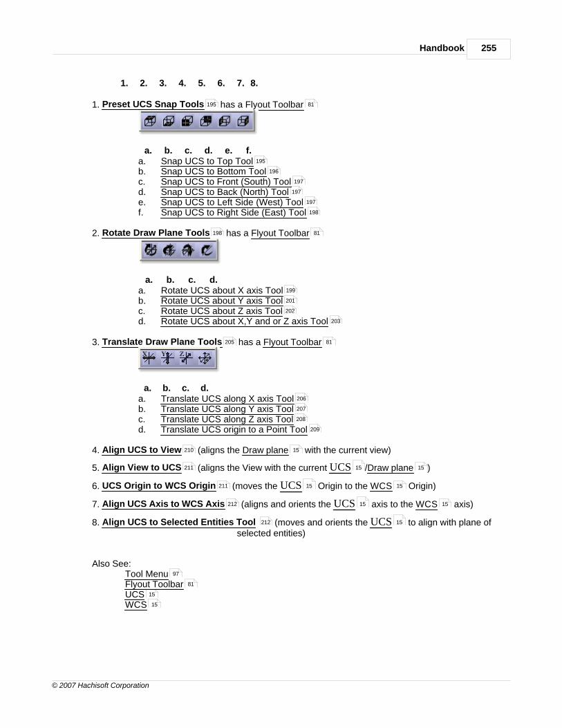
Handbook 255
© 2007 Hachisoft Corporation
1. 2. 3. 4. 5. 6. 7. 8.
1. Preset UCS Snap Tools has a Flyout Toolbar
a. b. c. d. e. f.
a. Snap UCS to Top Toolb. Snap UCS to Bottom Toolc. Snap UCS to Front (South) Toold. Snap UCS to Back (North) Toole. Snap UCS to Left Side (West) Toolf. Snap UCS to Right Side (East) Tool
2. Rotate Draw Plane Tools has a Flyout Toolbar
a. b. c. d.
a. Rotate UCS about X axis Toolb. Rotate UCS about Y axis Toolc. Rotate UCS about Z axis Toold. Rotate UCS about X,Y and or Z axis Tool
3. Translate Draw Plane Tools has a Flyout Toolbar
a. b. c. d.
a. Translate UCS along X axis Toolb. Translate UCS along Y axis Toolc. Translate UCS along Z axis Toold. Translate UCS origin to a Point Tool
4. Align UCS to View (aligns the Draw plane with the current view)
5. Align View to UCS (aligns the View with the current UCS /Draw plane )
6. UCS Origin to WCS Origin (moves the UCS Origin to the WCS Origin)
7. Align UCS Axis to WCS Axis (aligns and orients the UCS axis to the WCS axis)
8. Align UCS to Selected Entities Tool (moves and orients the UCS to align with plane ofselected entities)
Also See:Tool MenuFlyout ToolbarUCSWCS
195 81
195
196
197
197
197
198
198 81
199
201
202
203
205 81
206
207
208
209
210 15
211 15 15
211 15 15
212 15 15
212 15
97
81
15
15

hsCADCreator Help256
© 2007 Hachisoft Corporation
2.2.3.5 Rendering Toolbar
Description:The tools associated with the Rendering Toolbar are used to alter the rendering of the drawing.
1. 2. 3. 4. 5. 6. 7. 8.
1. 2D Wireframe Tool (Default Render mode)
2. 3D Wireframe Tool
3. Hidden Tool
4. Flat shaded Tool
5. Gouraud Shaded Tool
6. Flat Shaded With Edges Tool
7. Gouraud Shaded With Edges Tool
8. Regenerate Tool (Refreshes all entities and rendering within a drawing.)
Also See:Tool Menu
2.2.3.6 File Toolbar
Description:The tools associated with the File Toolbar are used to for the basic document operations of open,save, print, and help.
1. 2. 3. 4. 5. 6.
1. New (Create a new document)
2. Save (Save the active document)
3. Open (Open an existing named document)
4. Print/Plot (Print/Plot the active document)
5. Print/Plot Preview (Preview how the active document will print)
6. Help (Opens the help documentation)
Also See:File MenuFile FormatsPrint/Plot
213
214
214
214
215
216
216
217
97
14
14
93
286
14

Handbook 257
© 2007 Hachisoft Corporation
2.2.3.7 Library Toolbar
Description:The tools associated with the Library Toolbar are used for the quick management of useful entitiesand objects used within the drawing or for help in creating a drawing.
1. 2. 3. 4. 5. 6. 7. 8. 9. 10. 11. 12. 13. 14. 15.
1. Manage Layers
2. Quick Layer View
3. Manage Blocks
4. Manage Image Definitions
5. Manage Colors
6. Manage Text Styles
7. Manage Linetypes
8. Manage Multi Line Styles
9. Manage Hatch Styles
10. Manage Dimension Styles
11. Manage User Coordinate Systems
12. Manage External References
13. Manage Layouts
14. Manage Viewports
15. Manage Named Views
Also See:Manage Menu
2.2.3.8 Measure Toolbar
Description:The tools associated with the Measure Toolbar are used to for measuring length, area and angle.
1. 2. 3.
1. Measure Distance : Measure Distance along lines and arc.
2. Measure Area : Measure area of polygons.
3. Measure Angle : Measure angles
230
243
218
228
220
239
233
235
224
221
241
223
232
242
236
96
245
247
249

hsCADCreator Help258
© 2007 Hachisoft Corporation
Also See:Tool Menu
2.2.3.9 Snaps Toolbar
Description:The tools associated with the Snap Toolbar have the purpose of quickly enabling or disabling varioussnapping abilities within the drawing space.
1. 2. 3. 4. 5. 6. 7. 8. 9. 10. 11. 12. 13. 14. 15.
1. Enable /Disable (quickly turn on/off all snapping features)
2. End Point
3. Mid Point
4. Intersection
5. Center Point
6. Insertion
7. Nearest
8. Node
9. Parallel
10.Perpendicular
11.Polar
12.Quadrant
13.Tangent
14.Grid Snap (toggle the Grid Snapping feature)
15.Grid (toggle the grid visibility)
2.2.4 hsCADCreator Property Trees
hsCADCreator uses property trees to edit individual properties . Following property trees are
accessible in hsCADCreator :
· Selection Property Tree
· Tool Property Tree
· Snap Property Tree
· Drawing Property Tree
· Viewport Property Tree
97
72
72
72
72
72
72
72
72
72
72
72
72
72
74
74
79 77
259
260
261
262
263

Handbook 259
© 2007 Hachisoft Corporation
2.2.4.1 Selection Property Tree

hsCADCreator Help260
© 2007 Hachisoft Corporation
2.2.4.2 Tool Property Tree

Handbook 261
© 2007 Hachisoft Corporation
2.2.4.3 Snap Property Tree
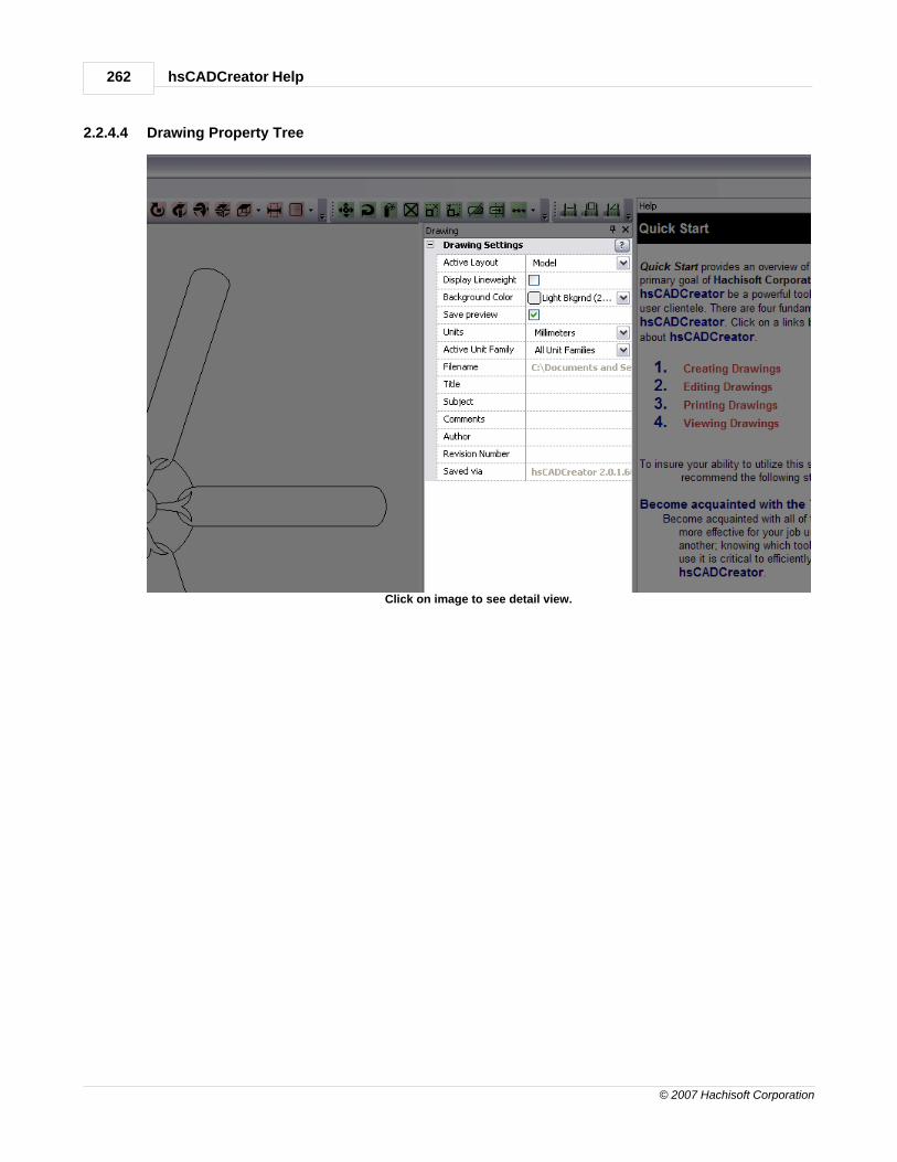
hsCADCreator Help262
© 2007 Hachisoft Corporation
2.2.4.4 Drawing Property Tree
Click on image to see detail view.

Handbook 263
© 2007 Hachisoft Corporation
2.2.4.5 Viewport Property Tree

hsCADCreator Help264
© 2007 Hachisoft Corporation
2.2.5 hsCADCreator Dialogs
Following dialogs are used in hsCADCreator:
· About Dialog
· Application Settings Dialog
· Print Dialog
2.2.5.1 About hsCADCreator Dialog
The About Dialog displays information about hsCADCreator and the current status of the License.
· Current Version Number for hsCADCreator
· Licensee Name: Name of License Owner or Company License Contact
· Licensee Company: Name of Company
· Licensee Email Email of License Owner or Company Contact
· Licensee Phone Number : Phone number of License Owner or Company Contact
· License Site Code : Generated
· Machine Code : Generated
· License Group Code : Code from online purchase or media case.
· Activation Code : Generated
2.2.5.2 Application Settings Dialog
Application Settings are program level settings. These settings are not saved with drawing, but
saved with hsCADCreator program. Whenever a new drawing or an existing drawing is openedpreviously set Application Settings are applied to it. Application Settings are accessible through
Application Settings Dialog. To access this dialog use Options ÆSettings... Menu item.
264
264
266
99

Handbook 265
© 2007 Hachisoft Corporation
Field Name Data Type Description
Use Auto Save Boolean Enable/disable auto save feature
Auto Save Interval Integer NumberTime interval between each autosave in minutes.
Auto Save Directory Folder PathPath to folder for temporary autosave files.
Drawings Directory Folder PathPath to current drawing'sdirectory.
Raster Directory Folder PathPath to current drawing's rasterfiles.
Plot Style Directory Folder PathPath to current drawing's plotstyle directory.
Tesselation Deviation Real Number
Value that controls the resolutionfor drawing non-linear curves.Lower the value, higher theresolution.
Region Selection UCS Real Number Tolerance for selecting region
79

hsCADCreator Help266
© 2007 Hachisoft Corporation
Tolerance that is on UCS plane.
Region Selection PointTolerance
Real NumberTolerance for selecting point thatis on UCS plane.
Decimal Places Integer NumberNumber of decimal places todisplay for all numbers used indrawing.
Default Drawing Units Multi-option selection boxDefault drawing units to be usedfor newly created drawings.
Active Unit Family Multi-option selection box Currently active unit family
Notification: Show Tool Options BooleanEnable/disable tool optionsnotifications.
Notification: Show ToolActivations
BooleanEnable/disable tool activationsnotifications.
Trim Trailing Zeros BooleanEnable/disable trimming oftrailing zeros.
Default Viewer Settings:Permanent Entity Snap Settings Entity Snap Settings
Default entity snap settings to beused for newly created drawings.
Default Drawing Settings Drawing SettingsDefault drawing settings to beused for newly created drawings.
2.2.5.3 Print Dialog
Print dialog gives access to print/plot settings . This dialog is accessible from File ÆPrint/Plotmenu item.
79
79
79
79
79
72
76
238

Handbook 267
© 2007 Hachisoft Corporation
2.2.6 Notify Window
The Notify Window tracks and displays a variety of information regarding the current state of thedesign process. Messages are displayed in order of arrival, with the latest message first. Messageshave one of 6 color-coded types.
The Notification Window is a Docking window . Docking windows are easy to position andsize. Docking windows may also be pinned or unpinned depending on preference. In theBasic Workspace Layout (default layout) the Notification window is docked to the bottom ofthe screen and is pinned . In the image below the Notification window in floating mode.
83 83
83 83 83
279 83
83 83

hsCADCreator Help268
© 2007 Hachisoft Corporation
Type Format Purpose
Option OPTION:ACTION Displays information on how toactivate special options in thecurrently active tool . OPTIONis the name of the choice, andACTION is the key or mouseaction used to activate the
80

Handbook 269
© 2007 Hachisoft Corporation
choice. These messages can beturned on or off in the SettingsDialog .
Instruction [INSTRUCTION] When a tool is expecting userinput, it uses these messages toexplain precisely what action isnecessary in order to continue.
Action ENTITY=(0,1,2) When a tool completes an actionof interest, it relates thisinformation back to the user.
Activate / Deactivate Tool Name ActivatedTool Name Deactivated
These messages occur when atool is activated or deactivated.These also show when Stackable Tools are beingused. These messages can beturned on or off in the SettingsDialog .
Warning Warning! "I" before "E" EXCEPTafter "C".
A tool uses these messages tonotify the user that input andactions may not have thedesired result, or if there exists apotential for error.
Error ERROR! "Ain't" ain't a word. This mechanism notifies theuser when a problem hasoccurred in the system, eitherthrough incorrect input or aninternal error.
2.2.7 Status Bar
Status Bar is located at the bottom of hsCADCreator's window. It shows the current status of
the hsCADCreator. It also shows brief description of a tool when user moves over mouse on anytool.
264
80
264

hsCADCreator Help270
© 2007 Hachisoft Corporation
2.2.8 Visual Aids
Beside the usual visual feedback of the mouse cursor, different tools will employ visual aidsto enhance the use of that tool. Different tools will use different visual aids as appropriate. Entity Creation Tools , typically use all of the visual aids.
Preview Entities
Entity Creation tools incorporate a preview entity and one or more entity design widgets.The preview entity shows what an entity would look like if you were to complete thecurrent process with the current choices. Thus, a line preview entity would show you whatthe line would look like if you were to click it. The preview entities are shown with dottedlines.
Cursor Icons
There are various cursor icons to give user a visual feedback of currently active tool . Thecursor icon changes whenever active tool is changed. Apart from active tool cursor icons, there is
also invalid input cursor icon . Whenever the input under cursor becomes invalid the cursor icon
changes to invalid input cursor .
103
80

Handbook 271
© 2007 Hachisoft Corporation
Cursor Targets
This is a very common visual aid. There are two types of cursor target representation. · Round cursor target ( )
· Square cursor target ( )
Round target cursor( ) is shown whenever user moves the mouse around before
selecting any point. Square target cursor ( ) is drawn whenever user selects some pointduring any tool step. In example below drawing arc with Start-Middle-End Arc Tool ,
start and middle points are already selected and are shown with square target . The
end point is still not selected and hence is shown as round target :
See Also:Grid
2.2.9 Keyboard Shortcuts
hsCADCreator is installed with color coded shortcuts from the keyboard for very easy access to
most frequently used tools. These shortcut keys may be modified by selecting the down arrow ( )
located to the right side any toolbar. Choose Add or Remove Buttons ÆCustomize... This willactivate the Customize window. Select the Keyboard tab. Within this tab it is possible assign,remove, or reset keyboard shortcuts for one or many commands. Note that the keyboard shortcutswill not be saved unless you save your current layout. Visit Saving My Layout for more information.
114
75

hsCADCreator Help272
© 2007 Hachisoft Corporation
Command Key Mapping dialog can be opened from Options ÆKey Accelerators... menu item. In thefollowing picture, each default shortcut key is shown with its toolbars color.
In hsCADCreator, default shortcut keys are as follows:
Shortcut Key Function
F1 Opens Help for hsCADCreator
Create Toolbar :
Shortcut Key Function
ESC Selection Tool
O Point Tool
L Line Tool
M Multiline Tool
P Planar Polyline Tool
251
101
105
106
108
110

Handbook 273
© 2007 Hachisoft Corporation
SHIFT + P 3D Polyline Tool
A Arc (Start, Middle, End) Tool
SHIFT + A Arc (Start, Center, End) Tool
C Circle Tool
E Ellipse Tool
D Aligned Dimension Tool
SHIFT + D Linear Dimension Tool
T Text Tool
H Hatch Tool
F Poly Face Mesh Tool
SHIFT + B Block Definition Tool
B Block Insertion Tool
I Image Insertion Tool
Modify Toolbar :
Shortcut Key Function
V Translate Tool
R Rotate Tool
X Explode Tool
DELETE Delete Tool
S Scale Uniformly Tool
SHIFT + S Scale Non-Uniformly Tool
[ Trim Tool
] Extend Tool
View Toolbar :
Shortcut Key Function
W Zoom to Window Tool
NUMPAD + Zoom In Tool
NUMPAD - Zoom Out Tool
SHIFT + E Zoom Extents Tool
Z Pan View Tool
NUMPAD 5 Top View Tool
NUMPAD 0 Bottom View Tool
NUMPAD 8 Front (South) View Tool
112
114
115
120
121
124
126
136
138
139
140
142
144
253
148
150
152
153
154
155
157
158
253
175
176
177
178
178
188
189
189

hsCADCreator Help274
© 2007 Hachisoft Corporation
NUMPAD 2 Back (North) View Tool
NUMPAD 4 Left Side (West) View Tool
NUMPAD 6 Right Side (East) View Tool
NUMPAD 1 Southwest View Tool
NUMPAD 3 Southeast View Tool
NUMPAD 7 Northwest View Tool
NUMPAD 9 Northeast View Tool
File Toolbar :
Shortcut Key Function
CTRL + Z Undo
CTRL + Y Redo
CTRL + A Select All
CTRL + C Copy
CTRL + V Paste
CTRL + SHIFT + V Paste as Block
CTRL + X Cut Selection
Draw Plane/UCS Toolbar :
Shortcut Key Function
ALT + NUMPAD 5 Snap UCS to Top View
ALT + NUMPAD 0 Snap UCS to Bottom View
ALT + NUMPAD 8 Snap UCS to Front View
ALT + NUMPAD 2 Snap UCS to Back View
SHIFT + RIGHT ARROW Rotate UCS about X-axis Tool
SHIFT + UP ARROW Rotate UCS about Y-axis Tool
SHIFT + DOWN ARROW Rotate UCS about Z-axis Tool
SHIFT + LEFT ARROW Rotate UCS
RIGHT ARROW Translate UCS along X-axis Tool
UP ARROW Translate UCS along Y-axis Tool
DOWN ARROW Translate UCS along Z-axis Tool
, Align UCS to Current View Tool
. Align Current View to UCS Tool
SHIFT+ > Align UCS Origin to WCS Origin
/ Align UCS to Selected Entities
190
190
191
191
192
193
192
256
254
195
196
197
197
199
201
202
203
206
207
208
210
211
212
212

Handbook 275
© 2007 Hachisoft Corporation
Library Toolbar :
Shortcut Key Function
ALT + E Manage Entire Library Tool
ALT + K Manage Layers Tools
ALT + L Quick Layer View Tool
ALT + B Manage Blocks Tool
ALT + I Manage Image Definitions Tool
ALT + C Manage Colors Tool
ALT + T Manage Text Styles Tool
ALT + Y Manage Linetypes Tool
ALT + M Manage Multiline Styles Tool
ALT + H Manage Hatch Styles Tool
ALT + D Manage Dimension Styles Tool
ALT + U Manage UCS Tool
ALT + R Manage External References Tool
ALT + W Manage Layouts Tool
ALT + V Manage Viewports Tool
ALT + N Manage Named Views Tool
2.2.10 Customizing Toolbars
hsCADCreator has the ability customize each toolbar. This customization includes the ability toshow hide individual toolbar buttons; creation/management of custom toolbars; activation anddeactivation of a toolbar's visibility; and quick key or key accelerator management.
Toolbar Show/Hide:
You may show/hide a toolbar/tool window by opening the ÆToolbar and select the name of
the toolbar you wish to show/hide. You may also select the down arrow ( ) located to the
right side of the toolbars and choose Add or Remove Buttons ÆCustomize... This willactivate a Customize window. To show/hide a toolbar simply check/uncheck the appropriatetoolbar in the list.
257
230
243
218
228
220
239
233
235
224
221
241
223
232
242
236

hsCADCreator Help276
© 2007 Hachisoft Corporation
Creating a Custom Toolbar:
It is possible to create a custom toolbar with the tools that you use most often. To create a
new toolbar select the down arrow ( ) located to the right side of the toolbars and choose
Add or Remove Buttons ÆCustomize... This wll will activate a Customize window. Bydefault the active tab should be Toolbars. Select the New... button found on the right handside of the Toolbars tab window. This will activate a small window where you can enter thename of the new toolbar. In the screenshot below we name our new toolbar "Custom 1". When you press OK a new empty toolbar will become visible in the upper left hand corner of
hsCADCreator.

Handbook 277
© 2007 Hachisoft Corporation
Once you have created the toolbar you will need to add commands to the currently emptytoolbar. To do this go to the Commands tab in the Customize window. Select a commandusing the mouse. Click and hold the left mouse button down and drag the selected commandto the empty toolbar. Release the left mouse button when you are over the top of the toolbar. If the command has a toolbar icon you will now see that icon in the toolbar otherwise you willsee the command's name.
Keyboard Accelerators:

hsCADCreator Help278
© 2007 Hachisoft Corporation
hsCADCreator has key accelerators that are setup by default on the installation of theprogram. To view the default key configurations visit . To modify a tool's default keyboard
accelerator select the down arrow ( ) located to the right side any toolbar and choose Add
or Remove Buttons ÆCustomize... This will activate the Customize window. Select theKeyboard tab. Within this tab it is possible assign, remove, or reset keyboard shortcuts forone or many commands. Note that the keyboard shortcuts will not be saved unless you saveyour current layout. Visit Saving My Layout for more information.
Toolbar Options:
Select the down arrow ( ) located to the right side any toolbar and choose Add or Remove
Buttons ÆCustomize... This will activate the Customize window. Select the Options tab.In this tab it is possible to manage the personalized menu data as well as change the toolbaricons size. You may also modify if the tool tips and their shortcut keys are shown when yourmouse hovers over the top of a tool for a certain amount of time. These options are onlysaved when you save your layout. Visit Saving My Layout

Handbook 279
© 2007 Hachisoft Corporation
2.2.11 Workspace Layout
The User Interface of hsCADCreator is designed to be a simple, yet powerful tool for dealing withdaily tasks in computer aided drafting and design. We know that you may wish to modify your layout tomore fully utilize the drafting space / tools / etc. We have provided the ability to manage how exactlyuser interface elements are displayed. This includes the easy movement and docking of all defaultand custom toolbars, Drawer windows, Flyout toolbars for like minded tools, and much more. Layouts
also contain the key accelerator configurations. Visit this link for more on changing the KeyboardShortcuts .
Basic and Advanced Layouts:
Installed by default is two different layouts designed for two groups of our users Basic andAdvanced. The Basic layout is designed to get the unfamiliar user more comfortable withthe use of hsCADCreator. This will typically have a visible Library Bar, Notification Window,and Help Window open and easily seen. The Advanced layout is designed more for ouradvanced user and every day usage of hsCADCreator. This layout will have most windowsset as unpinned such that the drawing space is maximized. Also in the Advanced layout alltoolbars and tools are visible.
271

hsCADCreator Help280
© 2007 Hachisoft Corporation
Custom Layouts:
The layout of hsCADCreator is fully customizable. This include placement and visibility ofalmost every user interface element including toolbars, windows, menus, etc. Below we willcover the steps to Save, Revert, Save As..., and Load From....

Handbook 281
© 2007 Hachisoft Corporation
Save my current layout:1. Modify the layout of the windows/toolbars as desired.
2. Go to Window Æ Layout Æ Custom Layout Æ Save from the main menu.3. After accepting to perform this operation a file will be created in the
hsCADCreator install directory under Layouts. The file's name is Current.xml.
Revert my current layout:
1. Go to Window Æ Layout Æ Custom Layout Æ Revert from the main menu2. After accepting that this will modify the current layout the layout will be modified to
the previously saved layout configuration.
Save to File:You may save your current configuration and saving to a file will save the active configurationwith which you could then share with friends and colleagues.
1. Go to Window Æ Layout Æ Custom Layout Æ Save As... from the main menu2. Select name and location and save the layout.
Load from File: This will allow you to specify which layout you wish to utilize. You may load a previouslysaved layout at any time. Note that if you do not Save the current layout after loading from a
file the layout will not be the same as the loaded file the next time hsCADCreator is started.
1. Go to Window Æ Layout Æ Custom Layout Æ Load From from the main menu2. Select the Layout file you wish to Load.3. Layout will be updated from the file
4. If you wish this layout to be the active layout the next time hsCADCreator is
opened you must go to Window Æ Layout Æ Custom Layout Æ Save to save thelayout as the current active layout.
Note: Every time you Save you will overwrite the Current.xml file with the activeconfiguration. Every time you Revert it will load the Current.xml file if one exists.
Changing Layouts:
You may change your layout at any time. You may change to the Basic layout by going to
Window Æ Layout Æ Basic Layout from the main menu. You may change to the
Advanced layout by going to the Window Æ Layout Æ Advanced Layout from the mainmenu.
2.2.12 Layer Window
The Layer Window is a quick and easy way to manipulate the layers of a drawing. For moreinformation on managing the layers and what symbols mean visit Quick Layer View Tool and/orManage Layers Tool .
243
230

hsCADCreator Help282
© 2007 Hachisoft Corporation
2.2.13 Library Window
The Library Window within hsCADCreator is designed to be a simple and powerful tool. Installedby default is a robust library of common architectural drawing items, furniture, appliances, generalshapes, and much more. You may simply click and drag a desired item from this window directly ontoyour drawing.
By default within the Basic Layout the Library Window is docked on the left side of the screen and279

Handbook 283
© 2007 Hachisoft Corporation
has the "All" category Selected.
Using the Library Window/Bar
To use the window bar move the mouse over the top of the preview item you wish to add tothe drawing. Click and hold down the left mouse button on the selection. In the image belowwe are selecting "Fan Ceiling 3". As you can see when you drag the item you will have acursor representation of that item.
Once you reach the drawing space the cursor representation will turn into the actualrepresentation of the item being added to the drawing.
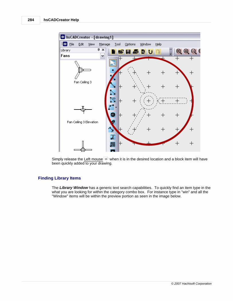
hsCADCreator Help284
© 2007 Hachisoft Corporation
Simply release the Left mouse when it is in the desired location and a block item will havebeen quickly added to your drawing.
Finding Library Items
The Library Window has a generic text search capabilities. To quickly find an item type in thewhat you are looking for within the category combo box. For instance type in "win" and all the"Window" items will be within the preview portion as seen in the image below.
15

Handbook 285
© 2007 Hachisoft Corporation
It is simple to change the category of items displayed within the Library Window. Click on thecategory drop down arrow and choose a category from the list. After the category is chosenthe preview list will be updated with that category's items. Seen below is changing thecategory from "Fans" to "Showers".
2.2.14 Help Window
By default hsCADCreator uses the Basic Workspace Layout . In this layout the Help Window islocated to the right hand side of the main window. With it easily visible, browsing through the help will
support a better understanding of hsCADCreator quicker. The Help Window is also a DockingWindow . This window is easily UnPinned to save valuable drawing space. For moreinformation on managing the window space visit Workspace Layout .
279
83 83
279

hsCADCreator Help286
© 2007 Hachisoft Corporation
Navigating Through the Help DocumentationTo move throughout the help documentation use the red links to navigate. Also, found at the top
of the window are three icons ( ). These icons are used to move aroundthroughout the help.
1. ( ) will move back to the home or start of the help documentation.
2. ( ) will move you forward to a page where you had recently gone back from.
3. ( ) will move you back to the previous page you had looked at.
2.3 Export
hsCADCreator can export the current drawing file to following formats.
· DWG
· DWF : Multi Layout
· DWF : Single Layout
· DXB
· DXF
· Email Attachment
· Image
· SVG
287
288
289
290
287
291
292
293
294

Handbook 287
© 2007 Hachisoft Corporation
2.3.1 DWG Format
DWG(Drawing) format is standard format for most of the CAD(Computer Aided Drafting) drawingfiles.
hsCADCreator supports DWG formats for open/edit/create drawings.
Following release formats of DWG are supported:DWG Release 9DWG Release 10DWG Release 12DWG Release 13DWG Release 14DWG Release 15DWG Release 18DWG Release 21
Exporter Dialog can be used to export existing drawing to any of above format.Exporter Dialog is accessed from File Menu :: Exporter... menu option.
Pressing Export... button creates new DWG file with given File Name.
2.3.2 DXF Format
DXF is a Drawing Interchange Format.
hsCADCreator supports DXF formats for open/edit/create drawings.
Following release formats of DXF are supported:
93

hsCADCreator Help288
© 2007 Hachisoft Corporation
DXF Release 9DXF Release 10DXF Release 12DXF Release 13DXF Release 14DXF Release 15DXF Release 18DXF Release 21
Exporter Dialog can be used to export existing drawing to any of above format.
Exporter Dialog is accessed from File Menu :: Exporter... menu option.
Pressing Export... button creates new DXF file with given File Name.
2.3.3 DWF : Multi Layout Format
DWF is a Drawing Web Format. This format is commonly used to upload drawings on website foreasy viewing and access.
hsCADCreator supports DWF: Multi Layout formats for open/edit/create drawings.
Following release formats of DWF : Multi Layout are supported:Binary DWF v6.0Zipped ASCII Encoded 2D Stream DWF v6.0
Exporter Dialog can be used to export existing drawing to any of above format.
Exporter Dialog is accessed from File Menu :: Exporter... menu option.
93
93

Handbook 289
© 2007 Hachisoft Corporation
Pressing Export... button creates new DWF file with given File Name.
2.3.4 DWF : Single Layout Format
DWF is a Drawing Web Format. This format is commonly used to upload drawings on website foreasy viewing and access.
hsCADCreator supports DWF : Single Layout formats for open/edit/create drawings.
Following release formats of DWF : Single Layout are supported:3-D DWF v6.01Binary DWF v6.0Zipped ASCII Encoded 2D Stream DWF v6.0Compressed Binary DWF v5.5Uncompressed Binary DWF v5.5ASCII DWF v5.5Compressed Binary DWF v4.2Uncompressed Binary DWF v4.2ASCII DWF v4.2
Exporter Dialog can be used to export existing drawing to any of above format.
Exporter Dialog is accessed from File Menu :: Exporter... menu option.93

hsCADCreator Help290
© 2007 Hachisoft Corporation
Pressing Export... button creates new DWF file with given File Name.
2.3.5 DXB Format
DXB is a Drawing Interchange Binary Format.
hsCADCreator can convert any opened drawing to DXB format:
Following release formats of DXB are supported:DXB Release 9DXB Release 10DXB Release 12DXB Release 13DXB Release 14DXB Release 15DXB Release 18DXB Release 21
Exporter Dialog can be used to export existing drawing to any of above format.
Exporter Dialog is accessed from File Menu :: Exporter... menu option.93

Handbook 291
© 2007 Hachisoft Corporation
Pressing Export... button creates new DXB file with given File Name.
2.3.6 Email Attachment
hsCADCreator can be used to attach current drawing in an email easily with Exporter Dialog.
Exporter Dialog is accessed from File Menu :: Exporter... menu option.93

hsCADCreator Help292
© 2007 Hachisoft Corporation
Pressing Export... button opens a new email to compose with current drawing already attached withemail.
2.3.7 Image Format
Currently hsCADCreator supports BMP (Bitmap) Image format. Using Exporter Dialog,
hsCADCreator can convert current drawing to BMP format.
Exporter Dialog is accessed from File Menu :: Exporter... menu option.93

Handbook 293
© 2007 Hachisoft Corporation
Pressing Export... button creates new BMP image file with given File Name.
2.3.8 PDF Format
PDF is a Portable Document Format.
hsCADCreator can convert any opened drawing to PDF format using Exporter Dialog.
Exporter Dialog is accessed from File Menu :: Exporter... menu option.93

hsCADCreator Help294
© 2007 Hachisoft Corporation
Pressing Export... button creates new PDF file with given File Name. If there is any plot style(stylesheet) associated with exported layout , it gets applied to pdf document.
2.3.9 SVG Format
SVG is a Scalable Vector Graphics format.
hsCADCreator can convert any opened drawing to SVG format using Exporter Dialog.
Exporter Dialog is accessed from File Menu :: Exporter... menu option.
232
93

Handbook 295
© 2007 Hachisoft Corporation
Pressing Export... button creates new SVG file with given File Name.
2.4 Supported Files and Formats
hsCADCreator can open a variety of files and formats and convert between variety of formats.
Input Formats that can be opened/viewed/edited by hsCADCreator are :
DWG DXFDWF : Multi LayoutDWF : Single Layout
Output Formats can be created/converted to from opened drawing in hsCADCreator are :
DWGDWF : Multi LayoutDWF : Single LayoutDXBDXFEmail AttachmentImagePDFSVG
287
287
288
289
287
288
289
290
287
291
292
293
294

hsCADCreator Help296
© 2007 Hachisoft Corporation
3 Licensing
· This software is controlled by a licensing system. A license key is a unique identifier used to activateyour copy of the software for use under the End-User License Agreement .
· This software requires a valid license key and running this software causes a License Key Entry
Dialog to appear until one is entered. By default, hsCADCreator is installed with an Evaluationlicense key which allows use for a trial period.
· Full version licenses may be purchased by opening the "Help" menu and clicking on the "PurchaseUpgrade to Full Version" menu item, or by visiting hsCADCreator website.
This software is controlled by a seat enforcing licensing system. The evaluation version of hsCADCreator allows a user a trial period of 5 days and/or 5 uses. After the evaluation term hasexpired the software is locked and cannot be used without an activation code. Hachisoft Corporationsells its software as license groups. A license group can contain one or more license seats. You maypurchase a license group by visiting (http blah).
3.1 Licensing Application
Licensing hsCADCreator:
1. Press the "Buy Full Version hsCADCreator" or use hsCADCreator website to buy FullVersion License Key.
2. Press the "Enter Full Version License Key" or use the Help ÆActivate License Menu
to activate hsCADCreator.
or
303
296

Licensing 297
© 2007 Hachisoft Corporation
3. The Manage hsCADCreator Licensing dialog will popup and will allow you to enter the"License Group Code" you purchased.
4. Press the "Activate" button to activate your copy of hsCADCreator.
Also See:Managing License GroupsAbout Dialog (License Interface)End-User License Agreement
298
264
303

hsCADCreator Help298
© 2007 Hachisoft Corporation
Trial Extensions
3.2 Managing License Groups
Managing License Groups:Hachisoft Corporation sells its software as license groups. A license group can contain one or
more license seats. On activation the licensing system ties a seat of hsCADCreator to a givencomputer. The licensing system supports adding more seats to a license group, activating seats,
removing seats and transferring seats of hsCADCreator from machine to machine.
The hsCADCreator setup can be passed command line parameters that allow remoteadministration for volume and site license management. These parameters are:
/VERYSILENT -- runs the installation without showing any of the GUI configurations and forms./hsKEY -- uses the passed parameter as the license group code for each installation ofhsCADCreator. On initialization, hsCADCreator will attempt to automatically activate a seat fromthe license group pool. This simplifies deployment of hsCADCreator across large groups ofusers.
Also See:Activating License SeatsRemoving License Seats
3.2.1 Activating a Seat
Web Activation:
Enter the "License Group Code" you received in your confirmation email (online purchases) orthe "License Group Code" on the cd case (media purchases), a unique "Seat Name" and press"Activate". Hachisoft Corporation will automatically check the validity of the "License Group
Code" and generate an "Activation Code" that will unlock hsCADCreator. Press "Done" to
use hsCADCreator… licensing is now complete.
302
298
300

Licensing 299
© 2007 Hachisoft Corporation
Phone Activation:
Call Hachisoft Corporation at 1 877 685 0760. Tell the operator the "License Group Code" youreceived in your confirmation email (online purchases) or the "License Group Code" on the cdcase (media purchases), the "Site Code", "Machine Code", and a unique "Seat Name". Theoperator will check the validity of the "License Group Code" and generate an "Activation Code"
that will unlock hsCADCreator. Enter the "Activation Code" that they told you and press "
Activate". Press "Done" to use hsCADCreator… licensing is now complete.

hsCADCreator Help300
© 2007 Hachisoft Corporation
3.2.2 Remove a Seat
Web Removal:
Press "Remove" to remove this license from current machine and restore into the "LicenseGroup" pool. Please note that the application will close on successful removal and you will be
required to activate a seat to use hsCADCreator on this computer. A dialog will ask you if you
really want to remove the seat. Press "Yes" to remove this seat of hsCADCreator and return it
to the "License Group" pool. hsCADCreator will return to its evaluation mode after asuccessful seat removal.
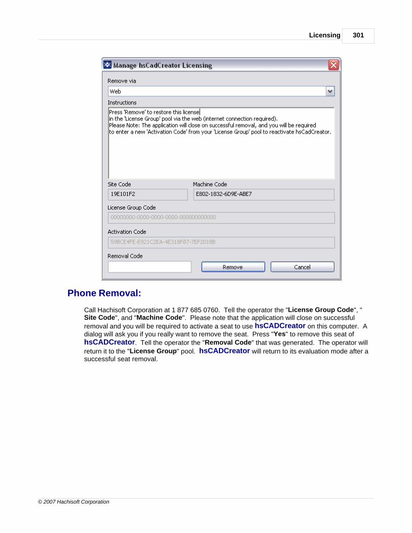
Licensing 301
© 2007 Hachisoft Corporation
Phone Removal:
Call Hachisoft Corporation at 1 877 685 0760. Tell the operator the "License Group Code", "Site Code", and "Machine Code". Please note that the application will close on successful
removal and you will be required to activate a seat to use hsCADCreator on this computer. Adialog will ask you if you really want to remove the seat. Press "Yes" to remove this seat ofhsCADCreator. Tell the operator the "Removal Code" that was generated. The operator will
return it to the "License Group" pool. hsCADCreator will return to its evaluation mode after asuccessful seat removal.

hsCADCreator Help302
© 2007 Hachisoft Corporation
3.3 Trial Extension
Thanks for trying our software! We want you to feel comfortable with our products and appreciate youtaking the time to do a thorough evaluation!
If you need more time simply click on Request Trial Extension button on the hsCADCreatorstartup screen.
15

Licensing 303
© 2007 Hachisoft Corporation
This will open hsCADCreator's New Trial Extension website in your browser. Fill in requiredinformation on the form and click on the Submit button. This will redirect you to a page listing your trialextension as well as send you a Trial Extension code at your specified email address.
Note that the Product and Version, Site Code, and Machine Code will automatically be filled with yourinformation.
3.4 License Agreements
· hsCADCreator End-User License Agreement
hsCADCreator utilizes the following open source libraries:
· Apache Xerces (XML processing library): Apache License Agreement
· OpenCascade (Modeling library): OpenCascade License Agreement
3.4.1 hsCADCreator End-User License Agreement
hsCADCreator End-User License Agreement
DEFINITIONSHACHISOFT means Hachisoft Corporation, a Washington State corporation, 115 W. Astor Ave Suite 208, Colville, Washington99114. EULA is the End-User License Agreement between you (either an individual or a single entity) and HACHISOFT.
SOFTWARE means all of the contents of the files, or other media provided with hsCADCreator, including but not limited
to HACHISOFT or third party computer information or software; related written explanatory materials or files
303
305
307

hsCADCreator Help304
© 2007 Hachisoft Corporation
(DOCUMENTATION); and UPDATES (e.g. upgrades, modified versions, updates, additions), and copies of the SOFTWARE, ifany, licensed to you by HACHISOFT. USE (or USING) means to access, install, download, copy or otherwise benefit from usingthe functionality of the SOFTWARE. ALLOWED SEATS means one (1) unless otherwise indicated under a valid volume licensegranted by HACHISOFT. COMPUTER means any device capable of consuming the SOFTWARE.
SOFTWARE LICENSEThe SOFTWARE is protected by copyright laws and international copyright treaties, as well as other intellectual property lawsand treaties. The SOFTWARE is licensed, not sold. Its USE requires a valid license and an appropriate number of ALLOWEDSEATS. If you do not agree to the terms of this EULA, do not install, copy, or USE the SOFTWARE.
GRANT OF LICENSEHACHISOFT grants you the rights described in this EULA provided that you comply with all terms and conditions of this EULA.
1. General License Grant. HACHISOFT grants to you a non-exclusive license to USE the SOFTWARE (i) for yourinternal use; (ii) for designing, developing, testing and demonstrating your software product(s); and (iii) forevaluation of the SOFTWARE. You may not reverse-engineer, decompile, or disassemble the SOFTWARE, exceptand only to the extent that such activity is expressly permitted by applicable law notwithstanding this limitation. You may not tamper with, circumvent or otherwise prevent the license validation mechanism (if any) fromoperating. You may not rent or lease the SOFTWARE. You may permanently transfer all of your rights under thisEULA, provided you retain no copies, you transfer all of the SOFTWARE, and the recipient agrees to the terms ofthis EULA. If the SOFTWARE is an UPDATE, any transfer must include all prior versions of the SOFTWARE.
2. Documentation. You may make and USE an unlimited number of copies of any DOCUMENTATION, providedthat such copies shall be USED only for personal internal purposes and are not to be republished or distributed.
RESERVATION OF RIGHTS AND OWNERSHIPHACHISOFT reserves all rights not expressly granted to you in this EULA. The SOFTWARE is protected by copyright and otherintellectual property laws and treaties. HACHISOFT or its suppliers own the title, copyright, and other intellectual property rightsin the SOFTWARE. You may not rent, lease, lend, or provide commercial hosting services with the SOFTWARE.
CONSENT TO USE OF DATA You agree that HACHISOFT and its affiliates may collect and use technical information gathered as part of the product supportservices provided to you, if any, related to the SOFTWARE. HACHISOFT may use this information solely to improve ourproducts or to provide customized services or technologies to you and will not disclose this information in a form that personallyidentifies you.
COMPLIANCE WITH LICENSES You agree that upon request from HACHISOFT, you will within thirty (30) days fully document and certify that USE of anyHACHISOFT SOFTWARE and/or UPDATES at the time of the request is in conformity with your valid licenses from HACHISOFT,and is supported by an appropriate number of ALLOWED SEATS.
EXPORT RESTRICTIONSYou recognize that the SOFTWARE is subject to U.S. export jurisdiction. You agree to comply with all applicable internationaland national laws that apply to the SOFTWARE, including the destination restrictions issued by the U.S. government.
TERMINATION Without prejudice to any other rights, HACHISOFT may terminate this EULA if you fail to comply with the terms and conditionsof this EULA. In such event, you must destroy all copies of the SOFTWARE and all of its component parts.
DISCLAIMER OF WARRANTIESTo the maximum extent permitted by applicable law, HACHISOFT and its suppliers provide the SOFTWARE, and supportservices (if any) as is and with all faults, and hereby disclaim all other warranties and conditions, whether express, implied orstatutory, including, but not limited to, any (if any) implied warranties, duties or conditions of merchantability, of fitness for aparticular purpose, of reliability or availability, of accuracy or completeness of responses, of results, of workmanlike effort, oflack of viruses, and of lack of negligence, all with regard to the SOFTWARE and the provision of or failure to provide support orother services, information, software, and related content through the software or otherwise arising out of the USE of thesoftware.
EXCLUSION OF DAMAGESTo the maximum extent permitted by applicable law, in no event shall HACHISOFT or its suppliers be liable for any special,incidental, punitive, indirect, or consequential damages whatsoever (including, but not limited to, damages for loss of profits orconfidential or other information, for business interruption, for personal injury, for loss of privacy, for failure to meet any dutyincluding of good faith or of reasonable care, for negligence, and for any other pecuniary or other loss whatsoever) arising outof or in any way related to the USE of or inability to USE the SOFTWARE, the provision of or failure to provide support or otherservices, information, software or otherwise arising out of the USE of the SOFTWARE, or otherwise under or in connection withany provision of this EULA, even in the event of the fault, tort (including negligence), misrepresentation, strict liability, breach of

Licensing 305
© 2007 Hachisoft Corporation
contract or breach of warranty of HACHISOFT or any supplier, and even if HACHISOFT or any supplier has been advised of thepossibility of such damages.
LIMITATION OF LIABILITY AND REMEDIESTo the maximum extent permitted by applicable law the entire liability of HACHISOFT and any of its suppliers under anyprovision of this EULA and your exclusive remedy hereunder shall be limited to the amount actually paid by you. The foregoinglimitations, exclusions and disclaimers shall apply, even if any remedy fails its essential purpose.
APPLICABLE LAWThis EULA is governed by the laws of the State of Washington.
SEVERABILITYThis EULA is the entire agreement between you and HACHISOFT relating to the SOFTWARE and the support services (if any)and they supersede all prior or oral or written communications, proposals and representations with respect to the SOFTWAREor any other subject matter covered by this EULA. To the extent the terms of any HACHISOFT policies or programs for supportservices conflict with the terms of this EULA, the terms of this EULA shall control. If any provision of this EULA is held to bevoid, invalid, unenforceable or illegal, the other provisions shall continue in full force and effect.
QUESTIONSShould you have any questions concerning this EULA, or if you desire to contact HACHISOFT for any reason, please use theaddress information enclosed in this EULA to contact HACHISOFT or visit HACHISOFT at http://www.hachisoft.com.
3.4.2 Apache License Agreement
Apache License, Version 2.0
TERMS AND CONDITIONS FOR USE, REPRODUCTION, AND DISTRIBUTION
1. Definitions.
"License" shall mean the terms and conditions for use, reproduction, and distribution as defined by Sections 1 through 9 of thisdocument.
"Licensor" shall mean the copyright owner or entity authorized by the copyright owner that is granting the License.
"Legal Entity" shall mean the union of the acting entity and all other entities that control, are controlled by, or are undercommon control with that entity. For the purposes of this definition, "control" means (i) the power, direct or indirect, to causethe direction or management of such entity, whether by contract or otherwise, or (ii) ownership of fifty percent (50%) or moreof the outstanding shares, or (iii) beneficial ownership of such entity.
"You" (or "Your") shall mean an individual or Legal Entity exercising permissions granted by this License.
"Source" form shall mean the preferred form for making modifications, including but not limited to software source code,documentation source, and configuration files.
"Object" form shall mean any form resulting from mechanical transformation or translation of a Source form, including but notlimited to compiled object code, generated documentation, and conversions to other media types.
"Work" shall mean the work of authorship, whether in Source or Object form, made available under the License, as indicated bya copyright notice that is included in or attached to the work (an example is provided in the Appendix below).
"Derivative Works" shall mean any work, whether in Source or Object form, that is based on (or derived from) the Work and forwhich the editorial revisions, annotations, elaborations, or other modifications represent, as a whole, an original work ofauthorship. For the purposes of this License, Derivative Works shall not include works that remain separable from, or merelylink (or bind by name) to the interfaces of, the Work and Derivative Works thereof.
"Contribution" shall mean any work of authorship, including the original version of the Work and any modifications or additionsto that Work or Derivative Works thereof, that is intentionally submitted to Licensor for inclusion in the Work by the copyrightowner or by an individual or Legal Entity authorized to submit on behalf of the copyright owner. For the purposes of thisdefinition, "submitted" means any form of electronic, verbal, or written communication sent to the Licensor or itsrepresentatives, including but not limited to communication on electronic mailing lists, source code control systems, and issuetracking systems that are managed by, or on behalf of, the Licensor for the purpose of discussing and improving the Work, but

hsCADCreator Help306
© 2007 Hachisoft Corporation
excluding communication that is conspicuously marked or otherwise designated in writing by the copyright owner as "Not aContribution."
"Contributor" shall mean Licensor and any individual or Legal Entity on behalf of whom a Contribution has been received byLicensor and subsequently incorporated within the Work.
2. Grant of Copyright License. Subject to the terms and conditions of this License, each Contributor hereby grants to You aperpetual, worldwide, non-exclusive, no-charge, royalty-free, irrevocable copyright license to reproduce, prepare DerivativeWorks of, publicly display, publicly perform, sublicense, and distribute the Work and such Derivative Works in Source or Objectform.
3. Grant of Patent License. Subject to the terms and conditions of this License, each Contributor hereby grants to You aperpetual, worldwide, non-exclusive, no-charge, royalty-free, irrevocable (except as stated in this section) patent license tomake, have made, use, offer to sell, sell, import, and otherwise transfer the Work, where such license applies only to thosepatent claims licensable by such Contributor that are necessarily infringed by their Contribution(s) alone or by combination oftheir Contribution(s) with the Work to which such Contribution(s) was submitted. If You institute patent litigation against anyentity (including a cross-claim or counterclaim in a lawsuit) alleging that the Work or a Contribution incorporated within theWork constitutes direct or contributory patent infringement, then any patent licenses granted to You under this License for thatWork shall terminate as of the date such litigation is filed.
4. Redistribution. You may reproduce and distribute copies of the Work or Derivative Works thereof in any medium, with orwithout modifications, and in Source or Object form, provided that You meet the following conditions:
1. You must give any other recipients of the Work or Derivative Works a copy of this License; and
1. You must cause any modified files to carry prominent notices stating that You changed the files; and
1. You must retain, in the Source form of any Derivative Works that You distribute, all copyright, patent, trademark, andattribution notices from the Source form of the Work, excluding those notices that do not pertain to any part of theDerivative Works; and
1. If the Work includes a "NOTICE" text file as part of its distribution, then any Derivative Works that You distributemust include a readable copy of the attribution notices contained within such NOTICE file, excluding those noticesthat do not pertain to any part of the Derivative Works, in at least one of the following places: within a NOTICE textfile distributed as part of the Derivative Works; within the Source form or documentation, if provided along with theDerivative Works; or, within a display generated by the Derivative Works, if and wherever such third-party noticesnormally appear. The contents of the NOTICE file are for informational purposes only and do not modify the License.You may add Your own attribution notices within Derivative Works that You distribute, alongside or as an addendumto the NOTICE text from the Work, provided that such additional attribution notices cannot be construed as modifyingthe License.
You may add Your own copyright statement to Your modifications and may provide additional or different license terms andconditions for use, reproduction, or distribution of Your modifications, or for any such Derivative Works as a whole, providedYour use, reproduction, and distribution of the Work otherwise complies with the conditions stated in this License.
5. Submission of Contributions. Unless You explicitly state otherwise, any Contribution intentionally submitted for inclusionin the Work by You to the Licensor shall be under the terms and conditions of this License, without any additional terms orconditions. Notwithstanding the above, nothing herein shall supersede or modify the terms of any separate license agreementyou may have executed with Licensor regarding such Contributions.
6. Trademarks. This License does not grant permission to use the trade names, trademarks, service marks, or product namesof the Licensor, except as required for reasonable and customary use in describing the origin of the Work and reproducing thecontent of the NOTICE file.
7. Disclaimer of Warranty. Unless required by applicable law or agreed to in writing, Licensor provides the Work (and eachContributor provides its Contributions) on an "AS IS" BASIS, WITHOUT WARRANTIES OR CONDITIONS OF ANY KIND, eitherexpress or implied, including, without limitation, any warranties or conditions of TITLE, NON-INFRINGEMENT,MERCHANTABILITY, or FITNESS FOR A PARTICULAR PURPOSE. You are solely responsible for determining the appropriatenessof using or redistributing the Work and assume any risks associated with Your exercise of permissions under this License.

Licensing 307
© 2007 Hachisoft Corporation
8. Limitation of Liability. In no event and under no legal theory, whether in tort (including negligence), contract, orotherwise, unless required by applicable law (such as deliberate and grossly negligent acts) or agreed to in writing, shall anyContributor be liable to You for damages, including any direct, indirect, special, incidental, or consequential damages of anycharacter arising as a result of this License or out of the use or inability to use the Work (including but not limited to damagesfor loss of goodwill, work stoppage, computer failure or malfunction, or any and all other commercial damages or losses), evenif such Contributor has been advised of the possibility of such damages.
9. Accepting Warranty or Additional Liability. While redistributing the Work or Derivative Works thereof, You may chooseto offer, and charge a fee for, acceptance of support, warranty, indemnity, or other liability obligations and/or rights consistentwith this License. However, in accepting such obligations, You may act only on Your own behalf and on Your sole responsibility,not on behalf of any other Contributor, and only if You agree to indemnify, defend, and hold each Contributor harmless for anyliability incurred by, or claims asserted against, such Contributor by reason of your accepting any such warranty or additionalliability.
END OF TERMS AND CONDITIONS
3.4.3 OpenCascade License Agreement
Open CASCADE Technology Public LicenseVersion 6.1 March 24, 2006
Open CASCADE S.A.S. releases and makes publicly available the source code of the software Open CASCADE Technology to thefree software development community under the terms and conditions of this license.
It is not the purpose of this license to induce you to infringe any patents or other property right claims or to contest validity ofany such claims; this license has the sole purpose of protecting the integrity of the free software distribution system, which isimplemented by public license practices. Many people have made generous contributions to the wide range of softwaredistributed through that system in reliance on consistent application of that system; it is up to the author/donor to decide if heor she is willing to distribute software through any other system and a licensee cannot impose that choice.
Please read this license carefully and completely before downloading this software. By downloading, using, modifying,distributing and sublicensing this software, you indicate your acceptance to be bound by the terms and conditions of thislicense. If you do not want to accept or cannot accept for any reasons the terms and conditions of this license, please do notdownload or use in any manner this software.
1. Definitions
Unless there is something in the subject matter or in the context inconsistent therewith, the capitalized terms used in thisLicense shall have the following meaning.
"Applicable Intellectual Property Rights"means (a) with respect to the Initial Developer, any rights under patents or patentsapplications or other intellectual property rights that are now or hereafter acquired, owned by or assigned to the InitialDeveloper and that cover subject matter contained in the Original Code, but only to the extent necessary to use, reproduce,modify, distribute or sublicense the Original Code without infringement; and (b) with respect to You or any Contributor, anyrights under patents or patents applications or other intellectual property rights that are now or hereafter acquired, owned byor assigned to You or to such Contributor and that cover subject matter contained in Your Modifications or in such Contributor'sModifications, taken alone or in combination with Original Code
"Contributor" means each individual or legal entity that creates or contributes to the creation of any Modification, including theInitial Developer.
"Derivative Program": means a new program combining the Software or portions thereof with other source code not governedby the terms of this License.
"Initial Developer": means Open CASCADE S.A.S., with main offices at 1, rue Isabey 92 500 RUEIL-MALMAISON France.
"Modifications": mean any addition to, deletion from or change to the substance or the structure of the Software. When sourcecode of the Software is released as a series of files, a Modification is: (a) any addition to, deletion from or change to thecontents of a file containing the Software or (b) any new file or other representation of computer program statements thatcontains any part of the Software. By way of example, Modifications include any debug of, or improvement to, the OriginalCode or any of its components or portions as well as its next versions or releases thereof.
"Original Code": means (a) the source code of the software Open CASCADE Technology originally made available by the Initial

hsCADCreator Help308
© 2007 Hachisoft Corporation
Developer under this License, including the source code of any updates or upgrades of the Original Code and (b) the objectcode compiled from such source code and originally made available by Initial Developer under this License.
"Software": means the Original Code, the Modifications, the combination of Original Code and any Modifications or anyrespective portions thereof.
"You" or "Your": means an individual or a legal entity exercising rights under this License
2. Acceptance of license
By using, reproducing, modifying, distributing or sublicensing the Software or any portion thereof, You expressly indicate Youracceptance of the terms and conditions of this License and undertake to act in accordance with all the provisions of this Licenseapplicable to You.
3. Scope and purpose
This License applies to the Software and You may not use, reproduce, modify, distribute, sublicense or circulate the Software,or any portion thereof, except as expressly provided under this License. Any attempt to otherwise use, reproduce, modify,distribute or sublicense the Software is void and will automatically terminate Your rights under this License.
4. Contributor license
Subject to the terms and conditions of this License, the Initial Developer and each of the Contributors hereby grant You aworld-wide, royalty-free, irrevocable and non-exclusive license under the Applicable Intellectual Property Rights they own orcontrol, to use, reproduce, modify, distribute and sublicense the Software provided that:
· You reproduce in all copies of the Software the copyright and other proprietary notices and disclaimers of the InitialDeveloper as they appear in the Original Code and attached hereto as Schedule "A" and any other notices ordisclaimers attached to the Software and keep intact all notices in the Original Code that refer to this License and tothe absence of any warranty;
· You include a copy of this License with every copy of the Software You distribute;
· If you distribute or sublicense the Software (as modified by You or on Your behalf as the case may be), You causesuch Software to be licensed as a whole, at no charge, to all third parties, under the terms and conditions of theLicense, making in particular available to all third parties the source code of the Software;
· You document all Your Modifications, indicate the date of each such Modifications, designate the version of theSoftware You used, prominently include a file carrying such information with respect to the Modifications andduplicate the copyright and other proprietary notices and disclaimers attached hereto as Schedule "B" or any othernotices or disclaimers attached to the Software with your Modifications.
For greater certainty, it is expressly understood that You may freely create Derivative Programs (without any obligation topublish such Derivative Program) and distribute same as a single product. In such case, You must ensure that all therequirements of this License are fulfilled for the Software or any portion thereof.
5. Your license
You hereby grant all Contributors and anyone who becomes a party under this License a world-wide, non-exclusive, royalty-freeand irrevocable license under the Applicable Intellectual Property Rights owned or controlled by You, to use, reproduce, modify,distribute and sublicense all Your Modifications under the terms and conditions of this License.
6. Software subject to license
Your Modifications shall be governed by the terms and conditions of this License. You are not authorized to impose any otherterms or conditions than those prevailing under this License when You distribute and/or sublicense the Software, save andexcept as permitted under Section 7 hereof.
7. Additional terms
You may choose to offer, on a non-exclusive basis, and to charge a fee for any warranty, support, maintenance, liability

Licensing 309
© 2007 Hachisoft Corporation
obligations or other rights consistent with the scope of this License with respect to the Software (the "Additional Terms") to therecipients of the Software. However, You may do so only on Your own behalf and on Your sole and exclusive responsibility. Youmust obtain the recipient's agreement that any such Additional Terms are offered by You alone, and You hereby agree toindemnify, defend and hold the Initial Developer and any Contributor harmless for any liability incurred by or claims assertedagainst the Initial Developer or any Contributors with respect to any such Additional Terms.
8. Disclaimer of warranty
The Software is provided under this License on an "as is" basis, without warranty of any kind, including without limitation,warranties that the Software is free of defects, merchantable, fit for a particular purpose or non-infringing. The entire risk as tothe quality and performance of the Software is with You.
9. Liability
Under no circumstances shall You, the Initial Developer or any Contributor be liable to any person for any direct or indirectdamages of any kind including, without limitation, damages for loss of goodwill, loss of data, work stoppage, computer failureor malfunction or any and all other commercial damages or losses resulting from or relating to this License or indirectly to theuse of the Software.
10. Trademark
This License does not grant any rights to use the trademarks, trade names and domain names "MATRA", "EADS MatraDatavision", "CAS.CADE", "Open CASCADE", "opencascade.com" and "opencascade.org" or any other trademarks, trade namesor domain names used or owned by the Initial Developer.
11. Copyright
The Initial Developer retains all rights, title and interest in and to the Original Code. You may not remove the copyright ©notice which appears when You download the Software.
12. Term
This License is granted to You for a term equal to the remaining period of protection covered by the intellectual property rightsapplicable to the Original Code.
13. Termination
In case of termination, as provided in Section 3 above, You agree to immediately stop any further use, reproduction,modification, distribution and sublicensing of the Software and to destroy all copies of the Software that are in Your possessionor control. All sublicenses of the Software which have been properly granted prior to termination shall survive any terminationof this License. In addition, Sections 5, 8 to 11, 13.2 and 15.2 of this License, in reason of their nature, shall survive thetermination of this License for a period of fifteen (15) years.
14. Versions of the license
The Initial Developer may publish new versions of this License from time to time. Once Original Code has been published undera particular version of this License, You may choose to continue to use it under the terms and conditions of that version or usethe Original Code under the terms of any subsequent version of this License published by the Initial Developer.
15. Miscellaneous
15.1 Relationship of Parties
This License will not be construed as creating an agency, partnership, joint venture or any other form of legal associationbetween You and the Initial Developer, and You will not represent to the contrary, whether expressly, by implication orotherwise.
15.2 Independent Development
Nothing in this License will impair the Initial Developer's right to acquire, license, develop, have others develop for it, market ordistribute technology or products that perform the same or similar functions as, or otherwise compete with, Modifications,Derivative Programs, technology or products that You may develop, produce, market or distribute.
15.3 Severability
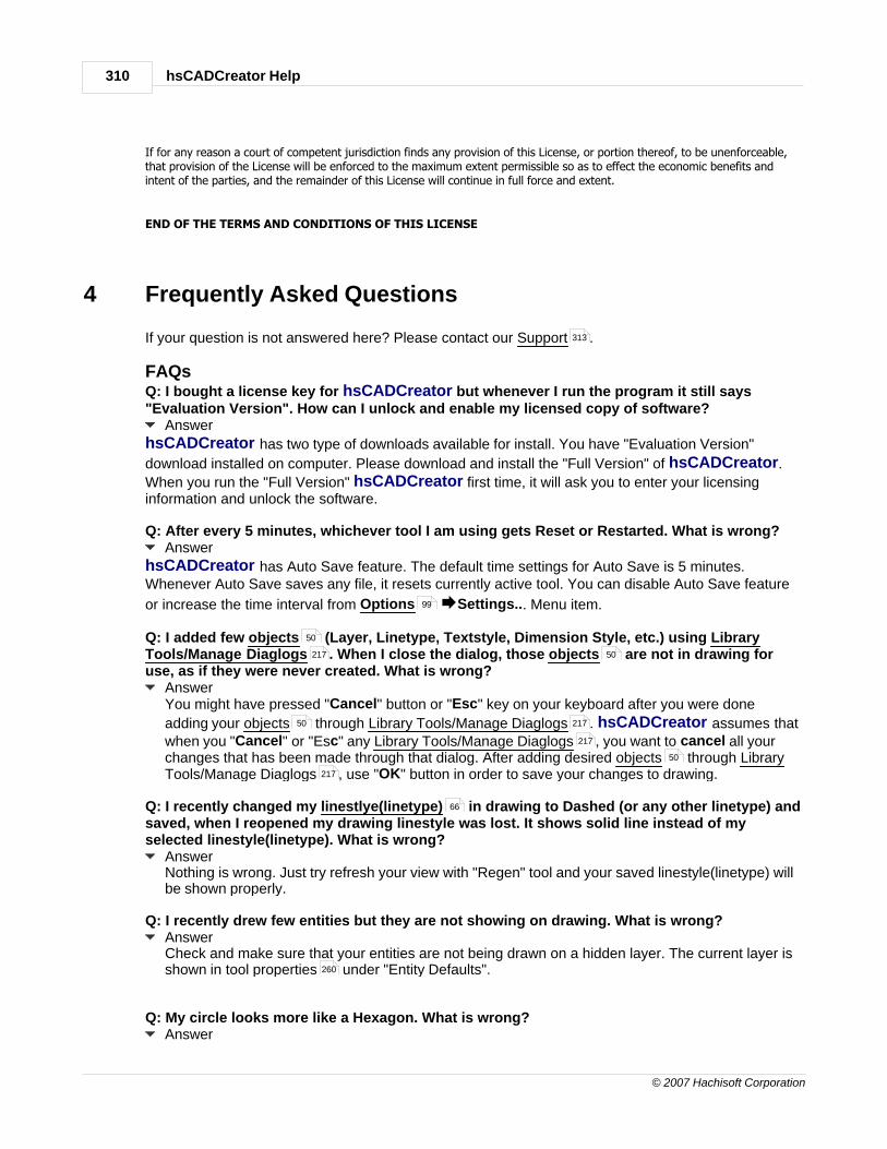
hsCADCreator Help310
© 2007 Hachisoft Corporation
If for any reason a court of competent jurisdiction finds any provision of this License, or portion thereof, to be unenforceable,that provision of the License will be enforced to the maximum extent permissible so as to effect the economic benefits andintent of the parties, and the remainder of this License will continue in full force and extent.
END OF THE TERMS AND CONDITIONS OF THIS LICENSE
4 Frequently Asked Questions
If your question is not answered here? Please contact our Support .
FAQsQ: I bought a license key for hsCADCreator but whenever I run the program it still says"Evaluation Version". How can I unlock and enable my licensed copy of software?
Answer
hsCADCreator has two type of downloads available for install. You have "Evaluation Version"
download installed on computer. Please download and install the "Full Version" of hsCADCreator.
When you run the "Full Version" hsCADCreator first time, it will ask you to enter your licensinginformation and unlock the software.
Q: After every 5 minutes, whichever tool I am using gets Reset or Restarted. What is wrong?Answer
hsCADCreator has Auto Save feature. The default time settings for Auto Save is 5 minutes.Whenever Auto Save saves any file, it resets currently active tool. You can disable Auto Save feature
or increase the time interval from Options ÆSettings... Menu item.
Q: I added few objects (Layer, Linetype, Textstyle, Dimension Style, etc.) using LibraryTools/Manage Diaglogs . When I close the dialog, those objects are not in drawing foruse, as if they were never created. What is wrong?
AnswerYou might have pressed "Cancel" button or "Esc" key on your keyboard after you were done
adding your objects through Library Tools/Manage Diaglogs . hsCADCreator assumes thatwhen you "Cancel" or "Esc" any Library Tools/Manage Diaglogs , you want to cancel all yourchanges that has been made through that dialog. After adding desired objects through LibraryTools/Manage Diaglogs , use "OK" button in order to save your changes to drawing.
Q: I recently changed my linestlye(linetype) in drawing to Dashed (or any other linetype) andsaved, when I reopened my drawing linestyle was lost. It shows solid line instead of myselected linestyle(linetype). What is wrong?
AnswerNothing is wrong. Just try refresh your view with "Regen" tool and your saved linestyle(linetype) willbe shown properly.
Q: I recently drew few entities but they are not showing on drawing. What is wrong?AnswerCheck and make sure that your entities are not being drawn on a hidden layer. The current layer isshown in tool properties under "Entity Defaults".
Q: My circle looks more like a Hexagon. What is wrong?Answer
313
99
50
217 50
50 217
217
50
217
66
260

Frequently Asked Questions 311
© 2007 Hachisoft Corporation
Just try refreshing your view with "Regen" tool.
Q: My middle mouse doesn't work for "Pan ". What is wrong?AnswerYou might have mouse software installed that allows you to configure actions on different mousebuttons. Change Middle Button's action to "Middle Click" to be able to "Pan" using middle mousebutton. These settings are accessible in Mouse Properties of your Operating System. MouseProperties are located under Control Panel.
Q: Entity snap settings are not saved when i close hsCADCreator. Every time I start
hsCADCreator I have to reselect my entity snaps through Snaps Tab . Is there any way tosave my entity snaps?
AnswerThe snap settings shown on Snaps Tab are only valid for current drawing. If a user wants to set
hsCADCreator's Entity Snaps they can be accessed from Options ÆSettings... Menu item.
Every time a new drawing is opened, it sets default entity snaps from hsCADCreator's Entity
Snaps. Snap settings changed through Options ÆSettings... Menu item will be saved with
hsCADCreator and will be activated everytime a new drawing is opened.
Q: I imported different linetypes from a .LIN file and changed linetype for one of my entities. But I stillsee the entity being drawn with solid line and not with the linetype that I have set. What is wrong?
AnswerMay be your linetype scale is not set properly. Select the targeted entity and increase LinetypeScale under selection properties .
Q: Why am I not able to hide a block insertion entity even though its layer is hidden?AnswerIf the block definition is made up of entities that are on layers other than "0", those entitiesretain their original layer behaviour. To have correct behaviour on hide/show layer andselection for block insertion entities, always make blocks from entities those are on layer "0".
Q: Why am I not able to select a block insertion entity in my drawing?AnswerMake sure that layer of block insertion entity is not hidden/frozen . If the block definition ismade up of entities that are on layers other than "0", those entities retain their original layerbehaviour. To have correct behaviour on hide/show layer and selection for block insertion entities,always make blocks from entities those are on layer "0".
Q: I want to delete Defpoints layer. But when I try to access it through Layer Manager Dialog,the "delete" button is not visible. How can I delete this layer?
Answer
Defpoints layer is created by hsCADCreator. This layer defines points used by dimension entitiies. Since Defpoints layer is created and used by system, this layer should not be deleted. To
restrict access to system created layers, the "delete" button is disabled. You can not delete thislayer.
Q: Why I am not able to see the Grip Points for the selected entities?AnswerGrip Points for entities are only shown when:
1. Only Selection Tool is active. i.e. You are not using Selection Tool as part of MoveTool , Rotate Tool , etc.2. The selected entities are not on OFF/FROZEN/LOCKED layer .
Q: I have a Block Insertion Entity on "Blocks" layer . When I turn OFF "Blocks" layer, my Block Insertion Entity is still visible. How can I hide Block Insertion Entity on
178
72
261
261
99
99
259
46 281
46 281
281 281
281
46
281 46 281
33
74
74
101 101
148 150
64
46 64 243
64 46 46

hsCADCreator Help312
© 2007 Hachisoft Corporation
"Blocks" layer ?AnswerBlock Insertion Entity is always created from Block Definition Object . Block Definition Object
preserves original layer of its individual entities except system default layer ("0"). Due tothis reason, eventhough Block Insertion Entity is on "Blocks" layer , its' individual entities areon different layers (original layers of entities). You can hide entities by either turning OFF theoriginal layer, OR by FREEZING "Blocks" layer.
Q: The Angular Dimension Tool rounds to the closest whole number. How can I change thatto nearest tenths, or nearest hundredth. For instance the NE direction is 22.5 degrees(compass).
AnswerThis can be achieved by creating a Dimension Style Object for required format. By default, theAngular Dimension Tool uses "ISO-25" Dimension Style Object . ISO-25 dimension stylespecifies decimal places in angular dimension as 0.
1. Use Manage Dimension Styles through menu or Library Toolbar toaccess Dimension Style Dialog . Create New dimension and select it. Change nameto required name(eg. myAnglularDimension). Scroll down on right hand pane to find"Dimension Text" properties. Click on "+" sign in front of "Dimension Text" to expand it.Set "Text Size" property to an appropriate value(eg. 2.0). Scroll down on right handpane to find "Angular Dimensions" properties. Click on "+" sign in front of "AngularDimensions" to expand it. Change "Precision (Angle)" property to required number ofdecimal places in angular measurments. Now activate Angular Dimension Tool .Specify Dim Style to be required dimension style(eg. myAngularDimension). Create newdimension.
2. Alternately, to change property on already created "Angular Dimension Entity", selectthe entity and edit its "Angular Dimensions" property to set "Precision (Angle) to requireddecimal places.
Q: While creating Dimension Entities using Dimension Tools , I select "Show Unit" butthe created dimension only shows number. It doesn't show unit along with it. How can Idisplay unit?
AnswerThere can be 2 resolutions for this:1. Check Drawing Settings . Dimension Entities gets drawing's dimension unit from "Units"
property of Drawing Settings . If "Units" is undefined/unspecified/empty Dimension Entitiescan not display unit text along with dimension. Change "Units" to appropriate unit to be used andcreate dimensions again.
2. Use Manage Dimension Styles to create Dimension Style Object . Set all properties asrequired. Change "Prefix and/or suffix" property in "Dimension Text" to set the Unit formeasurment. For detailed explanation see description of Dimension Style Object . Select thisnewly created Dimenstion Style Object when creating any dimension entity and unselect"Show Unit" property.
Q: I've changed my units in the property tree, and then drag an entity grip. Why did my unitschange back?
AnswerThe property tree gets rebuilt when a grip is used. The units will return to the drawing default forthat unit class.
Q: I am not able to use Nearest Entity Snap on an entity not on UCS-plane , Why?AnswerThe Nearest Entity Snap only works on current/active UCS-plane . Change your UCSto align with entity in question using modify UCS tools and then try to use Nearest Entity Snap
.
64
46 61
61 64 21
46 64
64
243
134
51
134 51
221 96 257
221
134
33 123
76 33
76 33
221 51
51
33
71 17
71 17 17
193
71

Frequently Asked Questions 313
© 2007 Hachisoft Corporation
Q: I used Trim Tool to trim more than one entities at a time(using box selection), but thetool trimmed some entities on wrong side of trimming line. Why?
AnswerTrim Tool trims entities on the side that is closest to the point where mouse button is released (inorder to finish the box selection). Try trimming single entity or only few entities at at time such thatmouse release point is close to the side that needs to be trimmed.
Q: I used Measure Area Tool to measure area of a non-planar/self intersecting polygon, butit shows me the area as Zero or Negative value. What is correct area?
AnswerMeasure Area Tool can not measure area of non-planar/self intersecting polygons correctly. Thebest way to calculate correct area is to dis-integrate the required polygon into simple polygonsconceptually and then use Measure Area Tool with Continuous Mode ON to find total area ofpolygons.
5 Support and Feedback
The most current support details can be found on the web at Hachisoft Support Website.
Email Support:The primary form of support contact is via email. Our support staff can be reached at:[email protected]
Forums:At Hachisoft Support Website we have user forums for our products. Please use these to check forknown bugs, view upcoming update details and progress, ask questions and give feedback.
Phone Support:If the other support options are insufficient, then phone support is also available:
1 (509) 685-0760 (Voice)1 (866) 685-6070 (Toll Free)1 (509) 684-1351 (Fax)
Feedback:Your feedback is extremely important to us. We create our products for you and we are interested inimproving them. Please use one of the three methods of contact mentioned above to provide us withfeedback and suggestions.
6 Version History
Visit hsCADCreator online version history to view the latest hsCADCreator changes.
157 21
157
247
247
247
hsCADCreator Help314
© 2007 Hachisoft Corporation
Index- . -.LIN 310
- 2 -2D Point 77
2D Polyline 26
2D space 15
2D Wireframe Tool 213
- 3 -3-Axial Array Tool 168
3D Point 77
3D Polyline 27
3D Polyline Tool 112
3D space 15
3D Wireframe Tool 214
- A -Acquire Seat 298
Action 267
Activate seat 298
Active Tool 80
Align Current View to UCS Tool 211
Align UCS Axis to WCS Axis Tool 212
Align UCS to Current View Tool 210
Align UCS to Selected Entities Tool 212
Aligned Dimension 35
Aligned Dimension Tool 124
Angular Dimension 42
Angular Dimension Tool 134
Application Settings 264
Arc 28
Arc Tools 113
area 310
Array Tool 159
3-Axial 168
Linear 163
Planar 165
Radial 160
Auto Save 310
Auto-hide 83
- B -Back View Tool 190
Bind external reference as block 223
Block
definition 61
insertion 46
reference 46
Block Definition 61
Block Definition Tool 140
Block Insertion 46
Block Insertion Tool 142
Block Reference 46
BMP 286
Boolean 77
Bottom View Tool 189
Buy
hsCADCreator 10
- C -Center Point 72
circle 30, 310
Circle Tool 120
Color 51
Concepts 20
2D Point 77
2D Polyline 26
3D Point 77
3D Polyline 27
aligned dimension 35
angular dimension 42
arc 28
block definition 61
block insertion 46
block reference 46
Boolean 77
circle 30
color 51
diametric dimension 41
dimension 33
dimension style 51
Drop-down list 77

Index 315
© 2007 Hachisoft Corporation
Concepts 20
ellipse 32
Entity 21
external references 60
hatch 45
hatch gradient 60
hatch pattern 61
hatch style 60
image definition 63
image insertion 47
layer 64
layout 64
line 23
linear dimension 36
linetypes 66
multi line 24
multi line style 67
Multiple option 77
ordinate dimension 38
Planar Polyline 26
plot settings 68
point 22
poly face mesh 46
radial dimension 39
Scientific Data 77
snap settings 71
text 43
text styles 69
Three-dimensional Point 77
Two-dimensional Point 77
UCS Point 77
user coordinate system 59
User Coordinate System Point 77
Vector 77
WCS Point 77
World Coordinate System Point 77
Contact Hachisoft 313
Convert to
DWF-Multi layout format 288
DWF-Single layout format 289
DWG format 287
DXB format 290
DXF format 287
Image Format 292
PDF Format 293
SVG Format 294
Co-ordinates
UCS 15
WCS 15
Create
2D Polyline 110
3D Polyline 112
Aligned Dimension 124
Angular Dimension 134
Arc 113
Arc (Start-Center-Angle) 117
Arc (Start-Center-Chord) 119
Arc (Start-Center-End) 115
Arc (Start-Middle-End) 114
Block Definition 140
Block Insertion 142
Circle 120
Diametric Dimension 132
Dimension 123
drawing 11
Ellipse 121
Hatch 138
Image Insertion 144
Line 106
Linear Dimension 126
Multi Line 108
Ordinate Dimension 128
Planar Polyline 110
Point 105
Poly Face Mesh 139
Radial Dimension 130
Text 136
Viewport 146
Create Tools 103
Cursor Targets 270
- D -Defpoints 310
Delete Tool 153
Dialog 88
About hsCADCreator 264
Application Settings 264
Dialogs in hsCADCreator 264
Print 266
Diametric Dimension 41
Diametric Dimension Tool 132
Dimension 33
aligned 35
angular 42
diametric 41
linear 36

hsCADCreator Help316
© 2007 Hachisoft Corporation
Dimension 33
ordinate 38
radial 39
Dimension style 51
Dimension Tool 123
Divide Viewport Tool 184
Docking 86
Docking window 83
Double 78
drag 15
Draw Plane Tools 193
Align Current View to Draw Plane 211
Align to Current View 210
Align UCS Axis to WCS Axis 212
Align UCS to Selected Entities 212
Move 205
Move Along X-axis 206
Move Along Y-axis 207
Move Along Z-axis 208
Move to Point 209
Move UCS Origin to WCS Origin 211
Preset UCS View Snap Tools 195
Rotate 198
Rotate About Line 203
Rotate About X-axis 199
Rotate About Y-axis 201
Rotate About Z-axis 202
Snap UCS to Back View 197
Snap UCS to Bottom View 196
Snap UCS to Front View 197
Snap UCS to Left View 197
Snap UCS to Right View 198
Snap UCS to Top View 195
Translate 205
Translate Along X-axis 206
Translate Along Y-axis 207
Translate Along Z-axis 208
Translate to Point 209
Draw Plane/UCS Toolbar 254
Drawing Property Tree 262
Drawing Settings 76
DWF 286
DWG 286
DXB 286
DXF 286
- E -Edit
drawing 12
Edit Menu 94
Ellipse 32
Ellipse Tool 121
End Point 72
Entity 21
2D Polyline 26
3D Polyline 27
aligned dimension 35
angular dimension 42
arc 28
block definition 61
block insertion 46
block reference 46
circle 30
diametric dimension 41
dimension 33
ellipse 32
hatch 45
image difinition 63
image insertion 47
line 23
linear dimension 36
multi line 24
ordinate dimension 38
paperspace viewport 49
Planar Polyline 26
point 22
poly face mesh 46
radial dimension 39
text 43
Entity Snap 72
permanent entity snap 72
temporary entity snap 72
Entity snap settings 310
Entity Toolbar 251
Erase 153
Error 267
Evaluation
hsCADCreator 10
Explode Tool 152
Export 286
DWF-Multi layout format 288
DWF-Single layout format 289

Index 317
© 2007 Hachisoft Corporation
Export 286
DWG format 287
DXB format 290
DXF format 287
Email attachment 291
Image Format 292
PDF Format 293
SVG Format 294
Extend Tool 158
Extension for trial 302
External references 60
- F -FAQ 310
features 17
Feedback 313
file 281
File formats 286
File Menu 93
File Toolbar 256
Flat Shaded Tool 214
Flat Shaded with Edges Tool 216
Float 78
Flyout Toolbar 80, 250
Flyout Toolbars 81
Frequently Asked Questions 310
Front View Tool 189
functions 17
- G -Getting started
hsCADCreator 9
Gouraud Shaded Tool 215
Gouraud Shaded With Edges Tool 216
grid 75
Grid Snap 74
Grip Points 74, 310
- H -Hatch 45
Hatch Gradients 60
Hatch Patterns 61
Hatch Styles 60
Hatch Tool 138
Help Menu 100
Hidden Tool 214
Hide pane 83
How to
create drawing 11
- I -Image
definition 63
insertion 47
Image Definition 63
Image Insertion 47
Image Insertion Tool 144
Insertion Point 72
Instruction 267
Integer, Number 78
intersecting 310
Intersection Point 72
Introduction
hsCADCreator 9
invalid input 270
Isometric Projection 15
- J -JPEG 286
JPG 286
- K -Keyboard Shortcuts 271
- L -Layers 64
layout 281
Layouts 64
left click 15
Left View Tool 190
Library Toolbar 257
Library Tools 217
Licenesing hsCADCreator 296
License
hsCADCreator 10

hsCADCreator Help318
© 2007 Hachisoft Corporation
License Groups 298
Licensing 296
LIN 310
Line 23
Line Tool 106
Linear Array Tool 163
Linear Dimension 36
Linear Dimension Tool 126
linestyle 310
linetype 310
Linetypes 66
load 281
- M -Manage Blocks Tool 218
Manage Colors Tool 220
Manage Dimension Styles Tool 221
Manage External References Tool 223
Manage Hatch Gradients Tool 225
Manage Hatch Pattern Tool 227
Manage Hatch Styles Tool 224
Manage Image Definitions Tool 228
Manage Layers Tool 230
Manage Layouts Tool 232
Manage License 298
Manage Linetypes Tool 233
Manage menu 96
Manage Multi Line Styles Tool 235
Manage Named Views Tool 236
Manage Plot Settings Tool 238
Manage Text Styles Tool 239
Manage Tools 217
Blocks 218
Colors 220
Dimension Styles 221
External References 223
Hatch Gradients 225
Hatch Pattern 227
Hatch Styles 224
Image Definitions 228
Layers 230
Layouts 232
Linetypes 233
Modelspace Viewport 242
Multi Line Styles 235
Named Views 236
Plot Settings 238
Quick Layer View 243
Text Styles 239
UCS 241
Manage UCS Tool 241
Manage Viewports Tool 242
Managing License Groups 298
measure 310
Measure Angle Tool 249
Measure Area Tool 247
Measure Distance Tool 245
Measure tape 245
Measure Toolbar 257
Measure Tools 244
Angle 249
Area 247
Distance 245
Menus 90
Mid Point 72
Mirror Tool 171
Modelspace 70
Modify Toolbar 253
Modify Tools 147
3-Axial Array Tool 168
Array 159
Delete 153
Explode 152
Extend 158
Linear Array Tool 163
Mirror 171
Move 148
Non-Uniform Scale Tool 155
Planar Array Tool 165
Radial Array Tool 160
Rotate 150
Translate 148
Trim 157
Uniform Scale Tool 154
Mouse
drag 15
left click 15
mode 15
right click 15
Move
grip points 74
toolbar 81
Move toolbar 81
Move UCS Origin Along X-axisTool 206

Index 319
© 2007 Hachisoft Corporation
Move UCS Origin Along Y-axisTool 207
Move UCS Origin Along Z-axisTool 208
Move UCS Origin to Point Tool 209
Move UCS Origin to WCS Origin Tool 211
Move UCS Tools 205
Multi line 24
Multi Line Style 67
Multi Line Tool 108
- N -Nearest Point 72
Node Point 72
Non-Uniform Scale Tool 155
Northeast View Tool 192
Northwest View Tool 193
Notify Window 267
- O -Object Snap 71, 72
Objects 50
color 51
dimension style 51
external references 60
hatch gradient 60
hatch pattern 61
hatch style 60
layer 64
layout 64
linetypes 66
modelspace viewport 70
multi line style 67
plot settings 68
text styles 69
user coordinate system 59
Option 267
Options Menu 99
Ordinate Dimension 38
Ordinate Dimension Tool 128
Orthographic Projection 15
OSnap 71
- P -Pan 310
Pan View Tool 178
Paperspace 49
Parallel Point 72
PDF 286
Perpendicular 15, 72
Planar Array Tool 165
Planar Polyline 26
Planar Polyline Tool 110
Plot Settings 68
Point 22
Point Tool 105
Polar Angle 72
Polar Point 72
Poly face mesh 46
Poly Face Mesh Tool 139
polygon 310
Polyline 26, 27
Pre-configured Viewport Tools 186
Preset UCS View Snap Tools 195
Snap UCS to Back View 197
Snap UCS to Bottom View 196
Snap UCS to Front View 197
Snap UCS to Left View 197
Snap UCS to Right View 198
Snap UCS to Top View 195
Preset View Snap Tools 187
Back 190
Bottom 189
Front 189
Left 190
Northeast 192
Northwest 193
Right 191
Southeast 192
Southwest 191
Top 188
drawing 14
Projection
Isometric 15
Orthographic 15
Property Tree 79
Property Trees 258
- Q -Quadrant Point 72
question 310
Quick Layer View Tool 243

hsCADCreator Help320
© 2007 Hachisoft Corporation
Quick start
hsCADCreator 9
- R -Radial Array Tool 160
Radial Dimension 39
Radial Dimension Tool 130
Real 78
redo 89
Regenerate Tool 217
Remove seat 300
Rendering Toolbar 256
Rendering Tools 213
2D Wireframe 213
3D Wireframe 214
Flat Shaded 214
Flat Shaded With Edges 216
Gouraud Shaded 215
Gouraud Shaded With Edges 216
Hidden 214
Regenerate 217
revert 281
right click 15
Right View Tool 191
Rotate About Eye Vector Tool 180
Rotate About Horizontal Vector Tool 182
Rotate About Vertical Vector Tool 181
Rotate Tool 150
Rotate Tools
About Horizontal Vector 182
Rotate UCS About Line Tool 203
Rotate UCS About X-axis Tool 199
Rotate UCS About Y-axis Tool 201
Rotate UCS About Z-axis Tool 202
Rotate UCS Tools 198
About Line 203
About X-axis 199
About Y-axis 201
About Z-axis 202
Rotate View 3D Tool 183
Rotate View Tools 179
3D 183
About Eye Vector 180
About Vertical Vector 181
- S -save 281
saved 310
Scale Tool
Non-Uniform Scale 155
Uniform Scale 154
Scientific Data 77
Seat Acquire 298
Seat activation 298
Seat removal 300
Selection Property Tree 259
Selection Tool 101
Show pane 83
Snap Property Tree 261
Snap Settings 71
Snap UCS to Back View Tool 197
Snap UCS to Bottom View Tool 196
Snap UCS to Front View Tool 197
Snap UCS to Left View Tool 197
Snap UCS to Rigtht View Tool 198
Snap UCS to Top View Tool 195
Southeast View Tool 192
Southwest View Tool 191
Space
2D 15
3D 15
Start-Center-Angle Arc Tool 117
Start-Center-Chord Length Arc Tool 119
Start-Center-End Arc Tool 115
Start-Middle-End Arc Tool 114
Status Bar 269
Stretch
grip points 74
Support 313
Supported file formats 295
SVG 286
- T -Tangent Point 72
tape 245
Text 43
Text Styles 69
Text Tool 136
Three-dimensional Point 77

Index 321
© 2007 Hachisoft Corporation
Tool Menu 97
Tool Property Tree 260
Tool Stack 80
Toolbar 250
Flyout 250
Tools 100
Create 103
Draw Plane 193
Library 217
Manage 217
Measure 244
Modify 147
Rendering 213
Selection 101
UCS 193
View 173
Top View Tool 188
Translate Tool 148
Translate UCS Origin Along X-axis Tool 206
Translate UCS Origin Along Y-axis Tool 207
Translate UCS Origin Along Z-axis Tool 208
Translate UCS Origin to Point Tool 209
Translate UCS Tools 205
Trial
hsCADCreator 10
Trial Extension 302
Trim Tool 157
Two-dimensional Point 77
- U -UCS 15
UCS Point 77
UCS Toolbar 254
UCS Tools 193
Align Current View to UCS 211
Align to Current View 210
Align UCS Axis to WCS Axis 212
Align UCS to Selected Entities 212
Move 205
Move Along X-axis 206
Move Along Y-axis 207
Move Along Z-axis 208
Move to Point 209
Move UCS Origin to WCS Origin 211
Preset UCS View Snap Tools 195
Rotate 198
Rotate About Line 203
Rotate About X-axis 199
Rotate About Y-axis 201
Rotate About Z-axis 202
Snap UCS to Back View 197
Snap UCS to Bottom View 196
Snap UCS to Front View 197
Snap UCS to Left View 197
Snap UCS to Right View 198
Snap UCS to Top View 195
Translate 205
Translate Along X-axis 206
Translate Along Y-axis 207
Translate Along Z-axis 208
Translate to Point 209
undo 89
Uniform Scale Tool 154
Updates 313
Upgrading hsCADCreator 296
User coordinate system 59
User Coordinate System Point 77
User Interface 90
- V -Vector 77
Version history 313
View
drawing 13
View Menu 94
View Toolbar 253
View Tools 173
Back View 190
Bottom View 189
Divide Viewport 184
Front View 189
Left View 190
Northeast View 192
Northwest View 193
Pan 178
Pre-configured Viewport 186
Preset View Snap 187
Right View 191
Rotate About Eye Vector 180
Rotate About Horizontal Vector 182
Rotate About Vertical Vector 181
Rotate View 179
Rotate View 3D 183
Southeast View 192

hsCADCreator Help322
© 2007 Hachisoft Corporation
View Tools 173
Southwest View 191
Top View 188
Zoom 175
Zoom Extent 178
Zoom In 176
Zoom out 177
Zoom to Window 175
Viewport
modelspace 70
paperspace 49
Viewport Property Tree 263
Viewport Tool 146
Visual Aids 270
- W -Warning 267
WCS 15
WCS Point 77
Window Menu 99
workspace 281
workspace layout 281
World Coordinate System Point 77
- Z -Zoom Extent Tool 178
Zoom In Tool 176
Zoom out Tool 177
Zoom to Window Tool 175
Zoom Tools 175
Zoom Extent 178
Zoom In 176
Zoom out 177
Zoom to Window 175