htgr technology course for the nuclear ct rl i iregulatory ... modules htgr...
TRANSCRIPT

HTGR Technology Course for the Nuclear R l t C i i
HTGR Component Technology –
Regulatory Commission May 24 – 27, 2010HTGR Component Technology
Steam Cycle Power Conversion SystemHTR Training Course Module 10bModule 10d
Reactor Cavity Cooling System
Lew LommersLew LommersAREVA
1

Outline
• RCCS functions and requirementsq• Passive heat removal in modular HTGRs• RCCS configurationg• RCCS design concepts• RCCS performance
2

RCCS System Functions and Requirements
• Normal operation– Control cavity concrete temperaturesControl cavity concrete temperatures– Cool reactor vessel (for some concepts)
• Accident conditions– Control cavity concrete temperatures– Control reactor vessel temperatures– Residual heat removal
• Passive operation during accidents (typical)• Safety-related heat removal system (typical)• Redundant loops (typical)
3

Outline
• RCCS functions and requirementsq• Passive heat removal in modular HTGRs• RCCS configuration• RCCS design concepts• RCCS performance
4
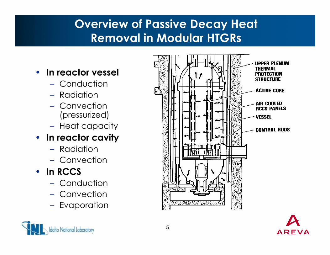
Overview of Passive Decay Heat Removal in Modular HTGRs
• In reactor vessel– Conduction– Radiation– Convection
( i )(pressurized)– Heat capacity
• In reactor cavity– Radiation– Convection
• In RCCS– Conduction– Convection– Evaporation
5
apo a o
Outline
• RCCS functions and requirementsq• Passive heat removal in modular HTGRs• RCCS configurationg• RCCS design concepts• RCCS performance
6

General RCCSConfiguration Considerations
• RCCS heat absorber structures shield cavity wall surrounding reactor vessel active core height
Air ducts– Air ducts– Panels– Stand pipes
• RCCS fluid circulates through heat absorber structures to remove heat from cavity
• RCCS fluidRCCS fluid– Air– Water
RCCS i l ti f t h• RCCS isolation from atmosphere– Open to atmosphere– Separated by HX
7
• Passive and/or active operation

Outline
• RCCS functions and requirementsq• Passive heat removal in modular HTGRs• RCCS configuration• RCCS design concepts
– MHTGR– NP-MHTGR– PBMR-DPP
AREVA– AREVA• RCCS performance
8

RCCS Concepts
• A large variety of possible RCCS conceptsA large variety of possible RCCS concepts
• Current vendor approaches provide examplespp p p
9

Overview of Air-Cooled RCCS Concept
10

MHTGR RCCS Concept
• Air-cooled• Natural circulation• Multiple flow pathsp p• Intake/exhaust
structure to mitigate t l ff texternal effects
11

MHTGR RCCS Arrangement
• Staggered riser channels create “black” surface
• Riser channels form t f it part of cavity
boundary
• Leaks provide Leaks provide escape path
• No loss of coolant
• Activation of air impurities considered during design
12
during design

NP-MHTGR RCCS Concept
• Water loop in cavity
• Heat pipes transfer heat to air in chimneychimney
• Redundant loops
• All natural • All natural circulation
• Head requirements • Head requirements for water and air loops leads to tall t t
13
structure

PBMR-DPP RCCS Concept
• Water-cooledBoil-off tanks
• Standpipes surround vessel
• 18 independent circuits
1 t k– 1 tank– 4 standpipes
• Active and passive • Active and passive modes
Stand Pipes
14
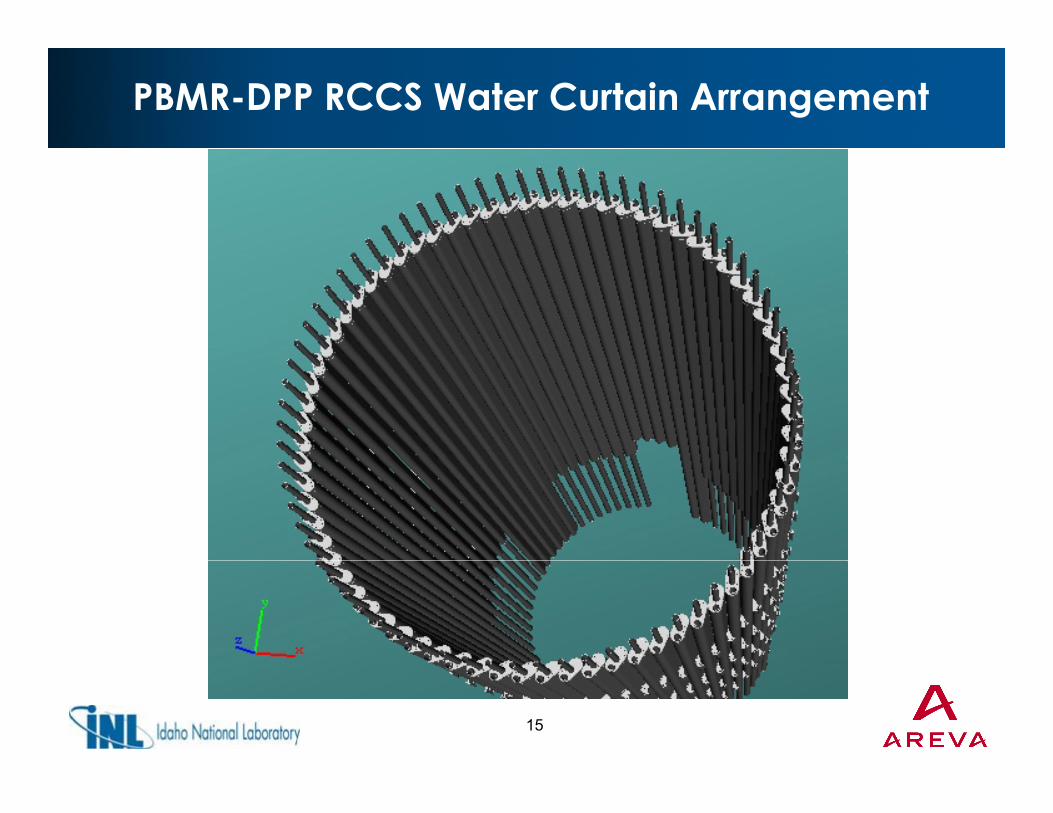
PBMR-DPP RCCS Water Curtain Arrangement
15

PBMR-DPP RCCS Active Mode
From EPCC
Steam outlet to atmosphereFilter
AB
P
MODULE ROOF
NRV
COMMON INLET HEADER
A
H
J
W
W
TANK
NRV
To EPCC C
N
Y
KCRAWLWAY
TANK ROOM
COMMONOUTLETHEADER
D G
F
TANK ROOMUPPER CAVITY
RADIATION SHIELDING FLOOR
E
F
LOWER CAVITY
ONLY ONE OF THE
RCCS ACTIVE MODE
16
ONLY ONE OF THEFOUR STANDPIPESARE SHOWN FOR
CLARITY

PBMR-DPP RCCS Passive Mode
From EPCC
Steam outlet to atmosphereFilter
AB
P
COMMON INLET HEADER
MODULE ROOF
NRV
H
J
W
W
TANK
NRV
To EPCC C
N
Y
KCRAWLWAY
TANK ROOM
COMMONOUTLETHEADER
D G
F
TANK ROOMUPPER CAVITY
RADIATION SHIELDING FLOOR
RCCS PASSIVE MODE
E
LOWER CAVITY
ONLY ONE OF THEFOUR STANDPIPES
RCCS PASSIVE MODE
17
FOUR STANDPIPESARE SHOWN FOR
CLARITY

AREVA RCCS Concept
Water Storageand Heat
ExchangerExchanger
Forced flowOutlet
Headers
• Water-cooled system• Redundant loops• System in red is safety-related
Natural Convection Flow System in red is safety related
– Operates in normal and accident modes
– Natural circulation driven
Panel wall Cavity Cooler
Reactor Vessel
• System in black is non-safety– Operates during normal
operationF d i l ti
Inlet Headers
18
– Forced circulation

AREVA RCCS Panel Wall Concept
• Cavity lined with ypanels of welded “finned” tubes
• Comparable to panels for HTR-Modul and HTR-Modul and NP-MHTGR
Wall panel sectionPanel tube cross section
19
Wall panel section

Outline
• RCCS functions and requirementsq• Passive heat removal in modular HTGRs• RCCS configurationg• RCCS design concepts• RCCS performance
20

Overall RCCS Performance Factors
• Performance for each function– Vessel heat removal
Cavity “cooling”– Cavity cooling– Concrete surface protection
• Heat removal mechanisms– Thermal radiation (~80%)– Convection (~20%)
• Overall reactor heat removal– Depends on reactor size and operating temperature– Typically 1-2 MWt during normal operation– Typically 1-3 MWt at accident peakyp y p
• Local effects– Local reactor effects– RCCS discontinuities
21
– RCCS discontinuities

RCCS Operating Modes
• Normal operation• Accident conditions• Accident conditions• Single loop operation• Active cooling• Active cooling• Passive cooling• Dryout (and refill)• Dryout (and refill)
– Typically BDBE• Failed RCCSFailed RCCS
– Typically BDBE
22
Performance Sensitivity
• RCCS heat removal rate is similar during normal operation and accidentsnormal operation and accidents– On-line monitoring of RCCS performance
confirms system status• Accident fuel temperatures are insensitive to
RCCS performancel i i • Vessel temperatures are more sensitive to
RCCS performance but still not a strong functionfunction
• Reactor cavity concrete temperatures are a strong function of RCCS performance
23
g p

Other Considerations
• Failure modes– Leaks– Blockage
Dryout– Dryout• Environmental effects
– Emissivity– Emissivity– Cavity atmosphere
• Performance monitoringPerformance monitoring– Overall heat removal– Local temperatures
24

Summary
• RCCS maintains cavity wall and reactor vessel temperaturestemperatures
• RCCS is a simple system• A wide variety of potential RCCS A wide variety of potential RCCS
configurations is possible• Fuel temperatures are insensitive to RCCS
performanceperformance• Concrete temperatures are a strong function
of RCCS performancep• Normal operation provides confirmation of
system status
25