hu-eclipse hdtv v02 technical manual - grass valley
TRANSCRIPT

ECLIPSE HDTV USER GUIDE
Technical Manual 1
Contents 1 Introduction 3
1.1 About this manual 3 2 Installation 7
2.1 Unpacking the Eclipse router 7
2.2 Transporting the unit 7
2.3 Preparing for rack mounting 8
2.4 Fitting and removing the doors 10 3 System components 12
3.1 Some possible system variants 12
3.2 Standard Eclipse router 12
3.3 Front view of the Eclipse router 14
3.4 Rear view of the Eclipse router 15
3.5 Modules used in Eclipse 16
3.6 Types of input module 16
3.7 Arrangement of crosspoint modules 18
3.8 Types of output module 20
3.9 Other Eclipse modules 22 4 Configuration 24
4.1 Types of Configuration 24
4.2 Setting up Eclipse hardware 24
4.3 Configuring the Eclipse PSU 1904 25
4.4 Configuring signal modules 26

ECLIPSE hdtv
2 Issue 2
4.5 Setting frame address switches 29
4.6 Connecting control signals 30
4.7 Eclipse software configuration 35
4.8 Firmware configuration 35
4.9 Local configuration 39
4.10 Remote configuration 47 5 Troubleshooting 54
5.1 System failure 55
5.2 Major system error 57
5.3 System error 57
5.4 Minor error 58
5.5 Diagnostics 59 6 Specification 60

ECLIPSE hdtv
Technical Manual 3
1 Introduction
Eclipse HD has been designed as a 64 x 64 routing switcher. Its modular architecture allows it to be part equipped to meet exact system requirements. By incorporating a wideband crosspoint module with HD or SD input and output cards, Eclipse HD permits routers to be created for either HD, SD or mixed HD/SD operation.
1.1 About this manual The information contained in this manual is divided into chapters, and is arranged as follows: • Introduction (this section) - contains general information about the Eclipse router
and this manual • Installation - describes how to unpack and install the Eclipse router • System components - contains information about type, location and fitting of
Eclipse modules • Configuration - contains information about hardware and software configuration • Troubleshooting - a guide to solving problems • Support information - contains warranty information and support, specifications
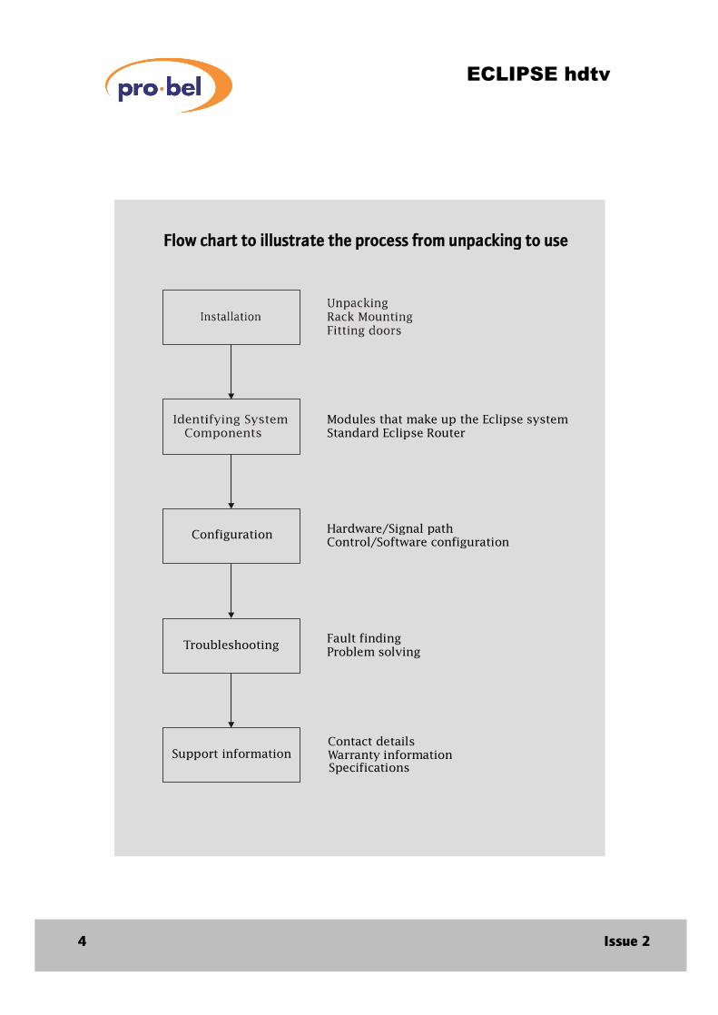
etc. It is intended that the chapters be read in order as illustrated by the following flow chart.
ECLIPSE hdtv
4 Issue 2
Modules that make up the Eclipse systemStandard Eclipse Router
Hardware/Signal pathControl/Software configuration
Fault findingProblem solving
Configuration
Troubleshooting
Support informationContact detailsWarranty informationSpecifications
Flow chart to illustrate the process from unpacking to use

ECLIPSE hdtv
Technical Manual 5
Terms and abbreviations used in this manual When discussing a product as versatile as the Eclipse router it is useful to have a common language. The following general terms and abbreviations are used throughout this manual: Dual output An output and a copy of that output on 2 BNC connectors Source/input Source and input are used interchangeably to describe a serial digital video signal supplied to the router by another piece of equipment Destination/output Destination and output are used interchangeably to describe a serial digital video signal supplied from the router to another piece of equipment Power supply unit The unit which converts mains (line) voltage to the (PSU) 5 Volts dc used internally Rack unit (RU) Standard unit of measure for rack height (1.75 inches, 44.1 millimetres)

ECLIPSE hdtv
6 Issue 2

ECLIPSE hdtv
Technical Manual 7
2 Installation
2.1 Unpacking the Eclipse router The Eclipse router is typically packed as shown below. A 64 x 64 Eclipse HD router is 7RU high.
2.2 Transporting the unit The unit is intended to be transported on the pallet until it is as close as possible to the equipment rack it is to be installed in.
WARNING: This equipment is extremely heavy.
Eclipse Technical Manual
A 7RU Eclipse router shown with external cardboard sleeve removed
Boxes containing mating connectors/doors/etc
Top packaging
Base packaging
This manual
ECLIPSE hdtv
8 Issue 2
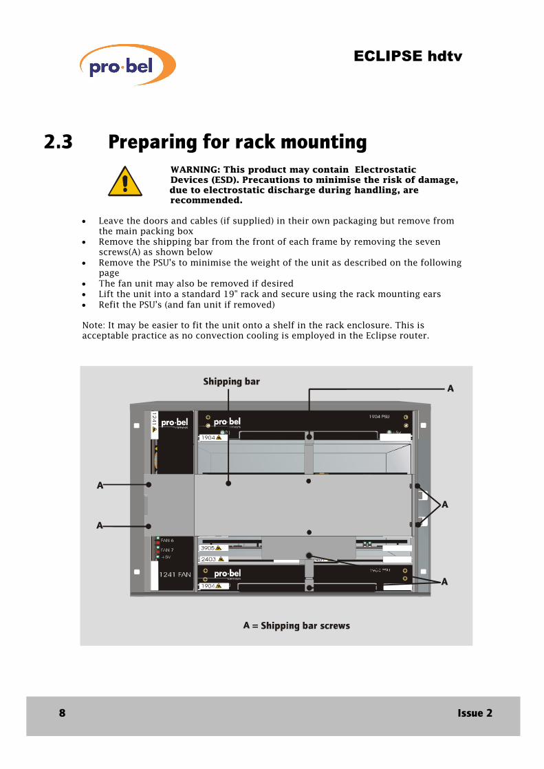
2.3 Preparing for rack mounting WARNING: This product may contain Electrostatic Devices (ESD). Precautions to minimise the risk of damage, due to electrostatic discharge during handling, are recommended.
• Leave the doors and cables (if supplied) in their own packaging but remove from
the main packing box • Remove the shipping bar from the front of each frame by removing the seven
screws(A) as shown below • Remove the PSU’s to minimise the weight of the unit as described on the following
page • The fan unit may also be removed if desired • Lift the unit into a standard 19" rack and secure using the rack mounting ears • Refit the PSU’s (and fan unit if removed) Note: It may be easier to fit the unit onto a shelf in the rack enclosure. This is acceptable practice as no convection cooling is employed in the Eclipse router.

ECLIPSE hdtv
Technical Manual 9
Removing and refitting the PSU The PSU is removed by pulling gently and evenly on the ejectors at the edge of the unit until it disengages from the motherboard 1 . With the ejectors pointing forwards the PSU may then be removed from the rack by pulling the folded handle at the front 2
When removing the PSU be careful to support it underneath. Take care as it is heavy.
To refit the PSU first engage it in the guides, then push it gently into the rack ensuring that the back of the ejectors engage into their slots. Once the PSU is in place push the ejectors inwards as shown in the diagram 3 .
Removing and refitting the fan The fan is removed in the same way as the PSU, except that it is fitted vertically within the frame, not horizontally. The ejectors are located at the top and bottom of the fan module.
2
1 3

ECLIPSE hdtv
10 Issue 2
2.4 Fitting and removing the doors The doors may be fitted now or left until the router is fully configured.
The fan modules provide adequate cooling for the Eclipse router even with the doors removed, although exhaust air may be forced out of the front of the bay.
Doors must be fitted during normal operation i.e. once the installation and configuration phases are complete.
To fit the door, first rotate the peg clockwise to unlock it (if locked) and hold it in the up position. Fit the door over the fixed hinge on the frame and close it to approximately 45 degrees. Now slide the moving latch along the door towards the hinge.
The peg will click into the door holding the moving latch over the hinge.
DROP IN3
2 SLIDE1 UNLOCK
ECLIPSE hdtv
Technical Manual 11
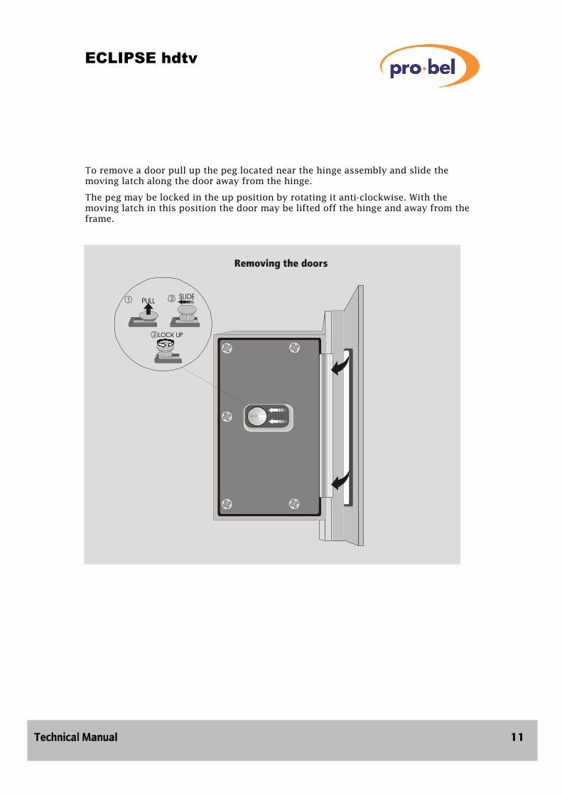
To remove a door pull up the peg located near the hinge assembly and slide the moving latch along the door away from the hinge.
The peg may be locked in the up position by rotating it anti-clockwise. With the moving latch in this position the door may be lifted off the hinge and away from the frame.
PULL1 2 SLIDE
3 LOCK UP

ECLIPSE hdtv
12 Issue 2
3 System components
3.1 Some possible system variants The Eclipse HDTV router is offered in a 64 x 64 frame. The modularity of the input and output modules provide a highly configurable approach to the distribution of high and standard serial digital video signals. Frames may be part equipped, starting from 4 x 2 to the full capacity of the installed unit.
In addition systems may have:
• Single or dual control modules
• Main or main and backup PSU
• Multiple references
Multiple references The Eclipse router is fitted with two switching reference inputs, Tri level sync (HDTV) and 525 line (analogue). Destinations may be set (via the control system switch timed, to either reference.
An optional sub-module (2402) may be fitted to the control module, allowing a 270, SDV reference to be used via the SDI reference input.
If however an SDV input is present on this input, the router control module will ignore the Tri Level sync input, in preference to it.
3.2 Standard Eclipse router In order to most simply describe Eclipse, this manual describes a standard system and then discusses variations on that theme. In reality no system is a distinct standard system compared to any other but for the purposes of this manual the standard system is defined as follows:
• 64 equalising HDTV inputs (non-reclocking)
• 64 dual reclocking HDTV outputs
• Single control
• Main and backup PSUs
• Forced air cooling
• 7RU high

ECLIPSE hdtv
Technical Manual 13
Single control Any Eclipse router may be specified with single or dual control. Standard routers are supplied with single control only. For dual operation it is necessary to fit a second control card adjacent to the main control card.
Main and backup PSUs Each 7 RU Eclipse frame has two positions for fitting PSUs. During normal operation two PSUs are fitted. In non critical applications a single PSU may be specified. In this instance the single PSU can be fitted in either of the two positions available.
Forced air cooling Each Eclipse frame has fitted at its left-hand edge a fan module. Air is drawn in from the left hand side of the bay and is exhausted at the right. It is therefore important, when installed, to ensure that the ventilation slots in the sides of the frames are not obstructed.

ECLIPSE hdtv
14 Issue 2
3.3 Front view of the Eclipse router 1 Main PSU
2 Backup PSU
3 Crosspoint module (1 of 2)
4 Control module (dual control shown)
5 Fan module

ECLIPSE hdtv
Technical Manual 15
3.4 Rear view of the Eclipse router 1 Input BNC connector (64 off)
2 Output BNC connector (128 off)
3 Control connector panel
4 Main IEC connector
5 Backup IEC connector
6 Fan fail/PSU alarm connector
7 Fuse holder with spare fuse (2)
8 Frame address switch
9 Input module (16 off)
10 Output module (32 off)

ECLIPSE hdtv
16 Issue 2
3.5 Modules used in the Eclipse HDTV router
We have already briefly mentioned the Eclipse fan and PSU modules. These are described in more detail in the following section. Other modules including input, crosspoint and output modules are also described in this section.
3.6 Types of input module The Eclipse HD router has two types of input module as follows:
• HDTV, 4 channel 3952
• SDV, 4 channel 3953
Each module carries a transient suppression diode which protects the card allowing it to be "hot-plugged". Each is also fitted with a fuse, so in the unlikely event of a fault on the card or of foreign material producing a short circuit, the card shuts down without affecting the rest of the system. LED power indication is visible through a window in the module label.
The input modules can be identified by the module number, which appears on the label. An example of an HDTV input module (type 3952) is shown below.
No user adjustment is required or is possible on the input modules.
HDTV input module 3952 This four channel module provides superlative video performance for HDTV signals, offering equalisation for up to 100 metres of:
• PSF 1/2
• Belden 8281
• An equivalent high quality cable
3952

ECLIPSE hdtv
Technical Manual 17
Should an SDV signal be fed into the 3952, then the signal will be passed correctly. The equalising circuit will provide equalisation for up to 100 metres of good quality cable as detailed for an HDTV signal.
SDV input module, 3953 As with the HDTV input module, this module provides excellent video performance, but for SDV signals, offering equalisation for up to 300 metres of
• PSF 1/2
• Belden 8281
• An equivalent high quality cable
It should be noted that this card will not operate with HDTV signals.
Fitting and removing input modules Input modules are fitted at the rear of the frame. Up to sixteen, four channel modules may be fitted in the frame providing 64 sources. Frames can therefore be sub-equipped in multiples of four inputs. The input modules are located in guides and secured using snap-lock fasteners. When fitting please note the following:
• Be careful to align the module in the guides
• Don’t use excessive force
• Ensure the module is fully engaged
• Check the green LED is lit
• Push the snap-lock fasteners in to lock the module after it is fully engaged
PULL
Snap-lockfastener Power led

ECLIPSE hdtv
18 Issue 2
To remove the module:
• First release the snap-lock fasteners by pulling on the pegs
• Remove the module by pulling on the BNC connectors while gently moving the module left and right.
3.7 Arrangement of crosspoint modules The 3905 is the only type of Eclipse HDTV crosspoint module:
• 64 x 32
The module incorporates a transient suppression diode protecting the card, allowing it to be hot-plugged. It is also fuse-protected.
Up to four modules may be fitted to one input frame providing a 128 x 64 crosspoint array, however of this 64 x 64 will be available. This is a limitation imposed by the number of input and output module positions.
The ‘hello’ led on the card edge indicates that the module is being addressed by the
The arrangement of modules within the 64 x 64 frame is shown in the table below.
Crosspoint position Source Destination Top of frame (Slot 4)
Unused
Unused
1 - 64
33 - 64
Bottom of Frame (Slot 1)
1 - 64
1 - 32
This is discussed in detail in chapter 5 - Configuration.

ECLIPSE hdtv
Technical Manual 19
Fitting and removing crosspoint modules Crosspoint modules are fitted and removed from the front of the input frame.
When fitting or removing these modules please note the following:
• Be careful to align the module in the guides
• Remove and refit the module by means of ejectors in the same way as the PSU
Due to the high density connector, some force is required to fit the crosspoint modules. Ensure that this is applied evenly to both ejectors.
A guiding system is incorporated with the connector to guarantee pin alignment.
Make sure that the module is pushed fully home.

ECLIPSE hdtv
20 Issue 2
3.8 Types of output module
The Eclipse HD router has two types of output module,
• HDTV, 2 Channel dual output 3960
• SDV, 2 channel dual output 3961
Both modules feature transient suppression diodes which protect the card allowing it to be “hot-plugged”. Each module also has a fuse, so that in the unlikely event of a fault on the card or foreign material producing a short circuit, the card shuts down without affecting the rest of the system.
LED power indication is visable through a window in the module label.
The output modules can be identified by the module number, which appears on the label. An example of an HDTV output module (type 3960) is shown below.
3960

ECLIPSE hdtv
Technical Manual 21
Fitting and removing output modules Output modules are fitted at the rear of the frame. Up to thirty two, two channel modules may be fitted in the frame providing 64 dual destinations. Frames can therefore be sub-equipped in multiples of two outputs. The output modules are located in guides and secured using snap-lock fasteners. When fitting please note the following:
• Be careful to align the module in the guides
• Don’t use excessive force
• Ensure the module is fully engaged
• Check the green LED is lit
• Push the snap-lock fasteners in to lock the module after it is fully engaged
To remove the module:
• First release the snap-lock fasteners by pulling on the pegs
• Remove the module by pulling on the BNC connectors while gently moving the module left and right.
PULL
Snap-lockfastener Power led
ECLIPSE hdtv
22 Issue 2
3.9 Other Eclipse modules
Control module (2403) The control cards are fitted at the front of the output frame.
Each control module has an 8 character alphanumeric display, and
features a menu system which can be navigated using the buttons situated adjacent to the display.
Control modules are fitted and removed from the frame using ejectors in the same way as crosspoint cards.
For detailed information regarding control module please refer to Chapter 4.
PSUs (1904) The PSU is a single integrated unit.
Front panel indication of mains (line input) status and internal five volt status is provided by means of green leds. PSU status is monitored by the control system. Alarm relay contacts are also available on the rear of the frame.
Line input voltage is auto-sensing and no user adjustment of the PSU is required.
Fan module (1241) The Fan module features seven high-performance DC fans.
Four fans provide cooling for the modules fitted in the front of the frame and three provide cooling for the input and output modules at the rear of the frame.
Fan module status is provided on the module edge by means of leds, red indicating a fault and green to indicate ‘healthy’.
In addition, alarm relay contacts are available at the rear of the frame and fan status is monitored by the control system.
To minimise inrush current when the fan module is powered up, it features phased start up. Two fans start after approximately 0.5 seconds, 2 more after about 1 second and the final three after 1.5 seconds. The fans can take several seconds to get up to operating speed so the status leds may initially indicate fan failure on power up.

ECLIPSE hdtv
Technical Manual 23

ECLIPSE hdtv
24 Issue 2
4 Configuration
4.1 Types of Configuration
Setting up an Eclipse router may be considered to consist of two phases:
• Hardware configuration
• Software configuration
Hardware configuration Ensuring that modules are fitted in the correct frames.
This involves:
• PSUs
• Fans
• Signal cards
• Cabling
• Setting frame address
Software configuration Ensuring that the router control is operating correctly and is communicating with the control system.
This involves:
• Firmware configuration (control card)
• Local configuration (via the card edge menu)
• Remote configuration (using a terminal attached to the config port)
4.2 Setting up Eclipse hardware Important: Before proceeding with this section it is important that you have read and understood chapter 3 - System components.

ECLIPSE hdtv
Technical Manual 25
9 way ’D’ socket
4.3 Configuring the Eclipse PSU 1904 The Eclipse PSU automatically configures itself to operate from mains input (line) voltage between:
• 90-264 Volts ac
and frequencies:
• 47-63 Hertz
No additional user set up or adjustment is required.
Fit the PSUs in the top or bottom of the frame (or in both positions for main and back up operation). Connect the mains (line) input to the top (for top PSU) or bottom (for bottom PSU) IEC connector, or both, as necessary.
Setting up PSU and fan alarm monitoring There is no requirement to set up alarm monitoring, but a connection is provided for each frame if it is desired to do this. Separate relay contacts are provided via a 9 way D type socket for each PSU and the fan module.
PSU/Fan monitoring
Pin Function
1 PSU2 Relay normally open
2 PSU2 Relay normally closed
3 PSU1 Relay common
4 Fan Relay normally open
5 Fan Relay normally closed
6 PSU2 Relay common
7 PSU1 Relay normally open
8 PSU1 Relay normally closed
9 Fan Relay common
Note: PSU1 is fitted at the top of the frame, and PSU2 at the bottom. The relay states shown above are for a powered frame, which is functioning correctly with the PSU’s fitted as detailed.
ECLIPSE hdtv
26 Issue 2
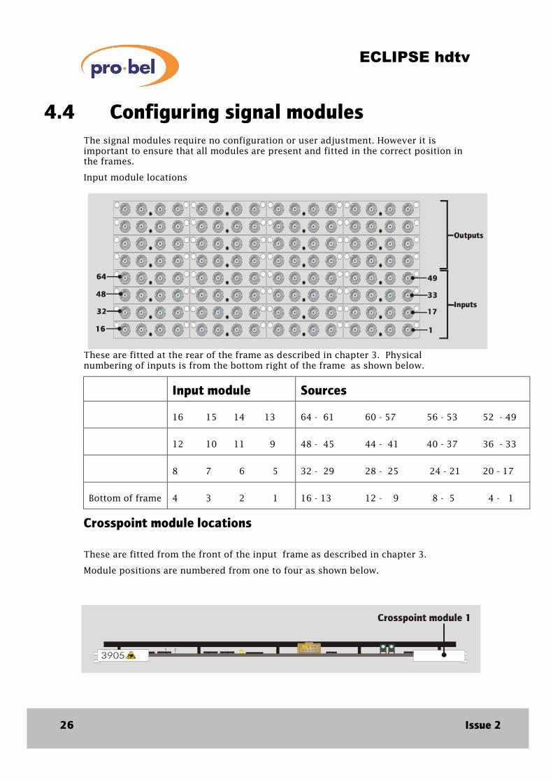
4.4 Configuring signal modules The signal modules require no configuration or user adjustment. However it is important to ensure that all modules are present and fitted in the correct position in the frames.
Input module locations
These are fitted at the rear of the frame as described in chapter 3. Physical numbering of inputs is from the bottom right of the frame as shown below.
Input module Sources
16 15 14 13
64 - 61 60 - 57 56 - 53 52 - 49
12 10 11 9
48 - 45 44 - 41 40 - 37 36 - 33
8 7 6 5
32 - 29 28 - 25 24 - 21 20 - 17
Bottom of frame
4 3 2 1
16 - 13 12 - 9 8 - 5 4 - 1
Crosspoint module locations These are fitted from the front of the input frame as described in chapter 3.
Module positions are numbered from one to four as shown below.

ECLIPSE hdtv
Technical Manual 27
Each crosspoint module has the capability to route any of its 64 sources to 32 destinations. The actual source and destination numbers that each card position corresponds to are shown in the table below
Crosspoint position Source Destination Top of frame (slot 4)
Unused
Unused
Unused
Unused
1-64
33-64
Bottom of frame (slot 1)
1-64
1-32
Example of crosspoint arrangement
To make this clearer here are some examples of which crosspoint modules are fitted for particular router sizes.
Size Modules fitted 32 x 32
Slot 1 only
64 x 64
Slot 1 and 2
Note: The connector on the front of each crosspoint module is for factory use only.

ECLIPSE hdtv
28 Issue 2
Output module locations These are fitted at the rear of the frame as described in chapter 3. Physical numbering of outputs is from the bottom right of the output module section to the top left of the frame as shown below.
Output module Destinations
Top of frame 32 31 30 29
64-63 62-61 60-59 58-57
28 27 26 25
56-55 54-53 52-51 50-49
24 23 22 21
48-47 46-45 44-43 42-41
20 19 18 17
40-39 38-37 36-35 34-33
16 15 14 13
32-31 30-29 28-27 26-25
12 11 10 9
24-23 22-21 20-19 18-17
8 7 6 5
16-15 14-13 12-11 10-9
Bottom of output block
4 3 2 1
8-7 6-5 4-3 2-1

ECLIPSE hdtv
Technical Manual 29
4.5 Setting frame address switches The frame address switch is located on the rear of each frame on the right hand side close to the bottom IEC connector. For the HDTV, 64 x 64 router this switch must be set to position 8.
Note: If the frame address switches are not correctly set, the router will not function properly.
Other settings Positions 1 to 7 and A to F are not used.

ECLIPSE hdtv
30 Issue 2
4.6 Connecting control signals Control signals are connected to the panel at the bottom of the first output frame.
In total there are 14 connectors on this panel:
1 1 x Controller change over port
2 3 x Router control ports
3 2 x Controller config ports
4 1 x Timecode port
5 Digital reference – SDI (BNC)
6 Unused (2 x Bnc)
7 Looping 525 reference – analogue (2 x BNC)
8 Looping tri-level sync reference (2 x BNC)
BNC connectors
For all BNC connectors the following applies:
BNC connector Inner
Signal
Outer
OV
ECLIPSE hdtv
Technical Manual 31
15 way ‘D’ type socket
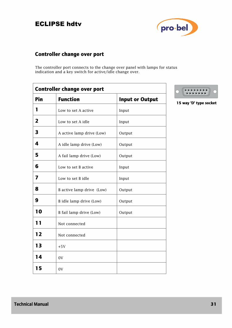
Controller change over port
The controller port connects to the change over panel with lamps for status indication and a key switch for active/idle change over.
Controller change over port
Pin Function Input or Output
1 Low to set A active
Input
2 Low to set A idle
Input
3 A active lamp drive (Low)
Output
4 A idle lamp drive (Low)
Output
5 A fail lamp drive (Low)
Output
6 Low to set B active
Input
7 Low to set B idle
Input
8 B active lamp drive (Low)
Output
9 B idle lamp drive (Low)
Output
10 B fail lamp drive (Low)
Output
11 Not connected
12 Not connected
13 +5V
14 0V
15 0V

ECLIPSE hdtv
32 Issue 2
9 way ’D’ socket
Router control port The router control port uses Pro-Bel general switcher protocol and defaults to:
• RS485
• 38,400 Baud
• 8 data bits
• 1 stop bit
• Even
Port 1 to 3
Pin Function
1 OV
2 TX-
3 RX+
4 OV
5 Not connected
6 OV
7 TX+
8 RX-
9 OV

ECLIPSE hdtv
Technical Manual 33
9 way ’D’ socket
Controller config ports There are 2 config ports (A and B) which are used for software configuration.
The protocol is as follows:
• RS232
• 9.6 KBaud
• 8 data bits
• 1 stop bit
• No parity
Controller config port 1/2
Pin Function
1 Not connected
2 TX (A or B)
3 RX (A or B)
4 Not connected
5 OV
6 DTR (A or B)
7 CTS (A or B)
8 RTS (A or B)
9 Not connected

ECLIPSE hdtv
34 Issue 2
9 way ’D’ socket
Timecode port The timecode port accepts standard linear timecode (LTC).
It is intended that timed/frame accurate switching of routes will be implemented as a future product enhancement.
Pin Function
1 LTC+
2 Not connected
3 Not connected
4 Not connected
5 Not connected
6 LTC
7 Not connected
8 Not connected
9 OV
ECLIPSE hdtv
Technical Manual 35
4.7 Eclipse software configuration There are 3 types of eclipse software configuration:
• Firmware configuration (control card)
• Local configuration (via the card edge menu)
• Remote configuration (using a terminal attached to the config port)
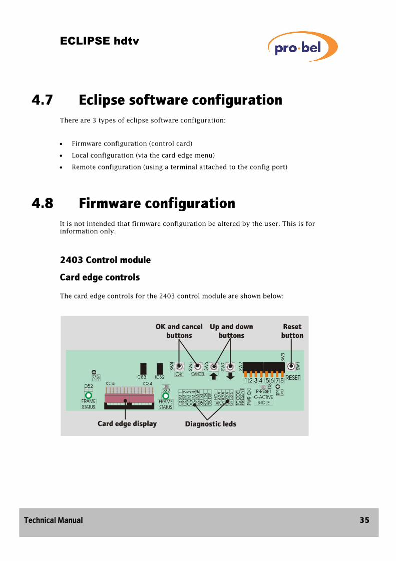
4.8 Firmware configuration It is not intended that firmware configuration be altered by the user. This is for information only.
2403 Control module
Card edge controls The card edge controls for the 2403 control module are shown below:
S W3
FRAMESTATUS
D52
FRAMESTATUS
D22
TCO
DE
PRES
ENT
PWR
OK D
8
R-RESETG-ACTIVE
B-IDLE
TP1
SW1
1 2 33 4 5 6 7 8 RESET
SW2
S W7
SW6
SW5
SW4
IC32IC83IC34
CO
M 1
CO
M 2
CO
M 3
CO
M 4
CO
MuP
XPT
STFI
X D
BD
B D
IF

ECLIPSE hdtv
36 Issue 2
Config switches There are 2, 4 way dual in line (DIL) switches on the 2403 control module as detailed below.
SW2 Software select
Switch Function Off (Up) On (Down)
1 Boot prom selection
Main software (Flash)
Monitor software(EPROM)
2 Not used
3 Not used
4 Not used
The default setting is all switches off.
SW3 Software function
Switch Function Off (Up) On (Down)
5 Boot prom function
Main software (Flash)
Monitor software(EPROM)
6 Monitor port baud rate (Test mode)
9600 Baud
38400 Baud
7 Diagnostics
Off
On
8 Not used
Not used
Not used
The default setting is all switches off.
Jumpers and reset button
SW1 Reset button Pressing this button causes the 2403 control module to perform a total hardware reset. When the button is released the module reboots.

ECLIPSE hdtv
Technical Manual 37
Jumpers There are 2 jumpers on the 2403 control module as defined below:
Jumper Function Out In
PL1 Watchdog disable
Enabled
Disabled
PL3 Flash/RAM. This maps 2M of RAM to the Flash location. This is used for debugging.
Flash
RAM
The default setting is all jumpers out.
Card edge leds There are 8 diagnostic leds, 2 status leds and 1 timecode led.
Diagnostic leds
Led No Function
1 Comms on 1st Router port (Flashes when data received)
2 Comms on 2nd Router port (Flashes when data received)
3 Comms on 3rd Router port (Flashes when data received)
4 Unused
5 Comms on Dual comms port (Flashes when data received)
6 Crosspoint set (flash)
7 Lights when the fixed database is in use
8 Database different (idle system only)
Timecode present led Lights if timecode is present on the selected input

ECLIPSE hdtv
38 Issue 2
Frame status led (Piped to front panel) This led is visible via a light pipe when the Eclipse door is closed. It provides pass/fail indication for the system.
Frame Status Function
Colour Description
RED Lights when any error is found. The nature of the error may be interrogated via the card edge display and buttons
GREEN OK - No errors found
BLUE Idle (Flashes when HI-CROSS monitor is running internal use only)
Internal status led
Processor Status
Colour Description
RED RESET - System is reset
GREEN ACTIVE - Flashes
BLUE IDLE - Flashes

ECLIPSE hdtv
Technical Manual 39
4.9 Local configuration Local configuration is carried out by means of push buttons on the module edge. Status is displayed on an eight character display.
What the buttons do:
Button Label Description
SW4 OK
Accept an action or move forward a menu level
SW5 CANCEL
Cancel an action or move back in a menu level
SW6 UP
Go to the previous selection (up the menu)
SW7 DOWN
Go to the next selection (down the menu)
Eight character display The control module (2403) is fitted with a card edge eight character display. Various messages may be shown depending on the menu selected. Messages with more than eight characters are displayed by scrolling the screen. In a dual control system cards may be active or idle. Obviously for single control systems, the card is always active.
Modules normally display active or idle. Other menus are then accessed using the up/down arrow keys. The exception to this is when there are faults in the system. In this circumstance the module will default directly to the faults menu.
S W3
FRAMESTATUS
D52
FRAMESTATUS
D22
TCO
DE
PRES
ENT
PWR
OK D
8
R-RESETG-ACTIVE
B-IDLE
TP1
SW1
1 2 33 4 5 6 7 8 RESET
SW2
S W7
SW6
SW5
SW4
IC32IC83IC34
CO
M 1
CO
M 2
CO
M 3
CO
M 4
CO
MuP
XPT
STFI
X D
BD
B D
IF

ECLIPSE hdtv
40 Issue 2
The control module display provides information about the entire router.
The idle display always provides less information than the active display. Always use the active display menu except for control module database transfer as explained below.
The 2403 ACTIVE system display
The top level active menu has four displays:
• ACTIVE
• Faults
• Modules
• Database
ACTIVE (1)
Faults
Modules
Database
No Effect
Faults sub list
Module menu
Database menu
OK
OK
OK
OK
OK
Up/Down
Up/Down
Up/Down
Up/Down
Cancel
Cancel
Cancel
Faults list OKCancel
Diagnostics*
*Special diagnostic mode only

ECLIPSE hdtv
Technical Manual 41
ACTIVE This is the default display. If no button is pressed for a minute the display will automatically return to ACTIVE.
Faults The text displayed will be either 'Faults - None' or 'Faults - XXX', where XXX is the current number of faults logged.
The faults list If the OK button is pressed from the faults main menu, the faults list will be displayed. If there are no faults then ‘NONE’ will be displayed. Otherwise faults will be displayed in the following order:
• Control (Comms to Idle system, Multidrop status port connections)
• Fan / PSU faults
• Crosspoint card faults
• Input card faults
• Output card faults
• Other card faults
Pressing the up / down buttons will move through the list sequentially. Pressing the OK button will skip to the next category of faults (e.g. If displaying crosspoint card faults, pressing OK will skip to the first Input card fault, if any).

ECLIPSE hdtv
42 Issue 2
The modules sub menu If the OK button is pressed from the modules main menu the modules sub menu will be displayed.
The modules submenu has two displays:
• Display
• Reconfigure
Display This is the first menu displayed after entering the modules sub menu. The down button goes to the reconfigure menu, the OK button goes to the recognised crosspoint display (or the crosspoint card list in the case of the frame interface module)
Modules
DisplayOK Recognised
crosspointblocks
Up/DownUp/Down
Up/Down
Up/Down
Up/Down
Up/Down
OK
Crosspointcards
Recognisedcrosspoint
blocks
Inputcards
Outputcards
Fan and PSU
Control cards
Cancel
Crosspointcards list
Recognised crosspointblocks list
Inputcards list
Outputcards list
OK
Cancel
OK
Cancel
OK
OK
OK
OK
Cancel
Cancel
Cancel
Cancel
Fan and PSUlist
Control cardslist

ECLIPSE hdtv
Technical Manual 43
Reconfigure This menu provides the ability to reconfigure the matrix according to the currently equipped cards. The display will show 'Reconfigure ?'. Pressing the OK button, requests confirmation, if OK is pressed again the installed modules tables are updated with the current installed modules. It is important that all required cards and frames are installed / connected and any cards added after will not be used. They will however be logged as faults.
The modules display sub menu This is displayed after pressing the OK button in the display sub menu of the modules main menu (see the diagram on the previous page).
The modules display sub menu has five displays:
• Recognised crosspoint blocks
• Crosspoint card list
• Input card list
• Output card list
• Fan and PSU list
• Control cards
Scrolling through these lists using the arrowkeys will show the module types and frame positions they occupy. Pressing OK when reaching a fan or PSU module will display the temperature of that module.
Recognised crosspoint blocks This produces a list of crosspoint blocks available for the currently configured cards. The list shown is in the form of 'SSS-SSS X DDD-DDD …' Where SSS-SSS is the minimum and maximum sources and DDD-DDD is the minimum and maximum destinations for a block. Multiple blocks can be shown if there are ‘holes’ in the matrix where crosspoints have been fitted.

ECLIPSE hdtv
44 Issue 2
The database sub menu
These are displayed after pressing the OK button in the database main menu.
There are five displays from the database main menu:
• Timecode selection
• Fixed/Editable
• Connected’s
• Force 625 (Tri-level syncs)
• Force 525

ECLIPSE hdtv
Technical Manual 45
Timecode selection This menu has 4 options as shown below.
Display Timecode Standard
TC = LTC (625) Linear timecode
PAL
TC = LTC (525) Linear timecode
NTSC
TC = VITC (625) Vertical interval timecode
PAL
TC = VITC (525) Vertical interval timecode
NTSC
Fixed/Editable This displays the current database in use:
• 'Fixed DB'
• 'Editable DB'
Connected’s on all ports This controls which control system ports are sent connected messages once a crosspoint has been set:
• All ports
• Single port
Force 625 This forces the reference for all sources to use the Tri Level Sync reference. Within the HD router, there is no 625 reference input as it has been set to provide a tri-level sync input.
Note: If a digital signal is present at the digital reference input and a 2402 sub module is fitted to the 2403, then the sources set to use the Tri-level sync reference will revert to using the digital reference.
Force 525 This works in the same way as the force 625 menu. It provides a way of setting all the sources to use the 525 reference.

ECLIPSE hdtv
46 Issue 2
The 2403 IDLE system display The following diagram shows the top level menu for the idle system:
The top level idle menu has four displays:
• IDLE
• Faults
• Modules
• Database
The only time it is necessary to use the menu on the idle control module is when a new control module is fitted into a system and requires a database transfer.
The first three menus report similar information to those on the active module.
Note: The faults list only displays control faults.
Transfer This menu provides the ability to transfer the database from the Active to the Idle system. The display will show 'Transfer DB ?'. Pressing the OK button, causes the database to be requested from the active system. During the transfer process the display will show 'Transferring …'. Once complete it will either show 'Successful' or 'Failed'
Up/Down
Up/Down
OK
OK
OK
OK
Idle
Faults Faults
Modulemenus
Database
Faults sub list
Transfer
Up/Down
Modules
Cancel
Cancel
Cancel

ECLIPSE hdtv
Technical Manual 47
4.10 Remote configuration Remote configuration is carried out by connecting a terminal to either controller config port.
Eclipse Editors This is a PC based terminal emulation package supplied on disk with the router. It writes information into the editable database on the control card using ASCII strings. Alternatively any RS232 terminal may be used.
The Eclipse editor may be used to download pre-set command files for purposes such as system initialisation. It also has the ability to upload a database which can be re-downloaded with or without change.
Eclipse controllers contain two databases, one fixed and the other editable. The fixed database is stored in Prom and can be recalled from the 8 character display on the Eclipse control module. The editable database can be updated either from the editor or the 8 character display on the control module.
It is possible to modify the editable database while the fixed database is in use. Any changes made will only take effect when the Eclipse controller is set to use the editable database.
Database data consists of:-
Router input parameters
Router port configuration data
Crosspoint trigger method
Checksum
The router can also be controlled using this method.
Dual Databases
The editor will work if plugged into either the active or idle control card.
If the editor is being used on the active controller then a database transfer from the active to the idle controller should be requested via the 8 character display on the idle controller.
N.B. Database transfer can only occur from active to idle card and can only be requested by the idle controller.
A database transfer also includes a transfer of tally table data for the number of destinations configured. Transfer of database information and tally table data may take up to one minute.

ECLIPSE hdtv
48 Issue 2
If the editor is being used on the idle controller then to transfer the database to the other ‘active’ controller the idle card must first become active. This is achieved by pressing the RESET button on the active card. The idle card now becomes the active card and vice versa. The ‘new’ idle card can now initiate a database transfer request.
Syntax Command CP
Configure RS485 router ports
CV
Crosspoint trigger method
IP
Input Parameters
S
Set Crosspoints
IM
Read installed modules to re-configure system
RS
Reset system
D
Diagnostics
T
Test
?
Help
?XX
Detail Help Command
Help The system provides a local help facility consisting of a display of the command library and a line description of individual command formats.
Configurable Features
A summmary of the Eclipse editor, ASCII based, commands are shown below:
Eclipse Editor Protocol This section details the Eclipse editor ASCII commands. By omitting the parameters enclosed by the square brackets, the command is turned into an interrogate function. In this instance, the information returned is the omitted item(s).

ECLIPSE hdtv
Technical Manual 49
When commands are used as interrogate functions, the returned answer is formatted in such a way that it can be saved to a disk file on a PC (using the supplied PC package ) and re-downloaded again at a later date (when using the PC package provided).
Help (?)
Displays a complete list of all available commands.
?
Detailed Help Command (?XX)
Gives information on a particular command syntax.
?command
Command Any command, e.g. RS
Error Responses
There are three basic types, which are:
Invalid Command Returned if an invalid command was entered
Invalid Data in Command Returned if invalid data was entered in command
Command Line Too Long Returned if a command line of more than 100 characters was entered

ECLIPSE hdtv
50 Issue 2
Configure Ports (CP)
Sets protocols and transmission characteristics of the three router control ports.
CP[,port][,baud rate,data bits,parity,stop bits]
Port type:
A = RS485 router port 1
B = RS485 router port 2
C = RS485 router port 3
E = All 3 router ports
Baud rate: 23 = 230400
11 = 115200
57 = 57600
38 = 38400
19 = 19200
96 = 9600
48 = 4800
24 = 2400
12 = 1200
3 = 300
Number of data bits: 7 or 8 (N.B. Pro-Bel protocols always require 8 bits)
Parity: E = Even
O= Odd
N = None
Stop bits: 1 or 2
ECLIPSE hdtv
Technical Manual 51
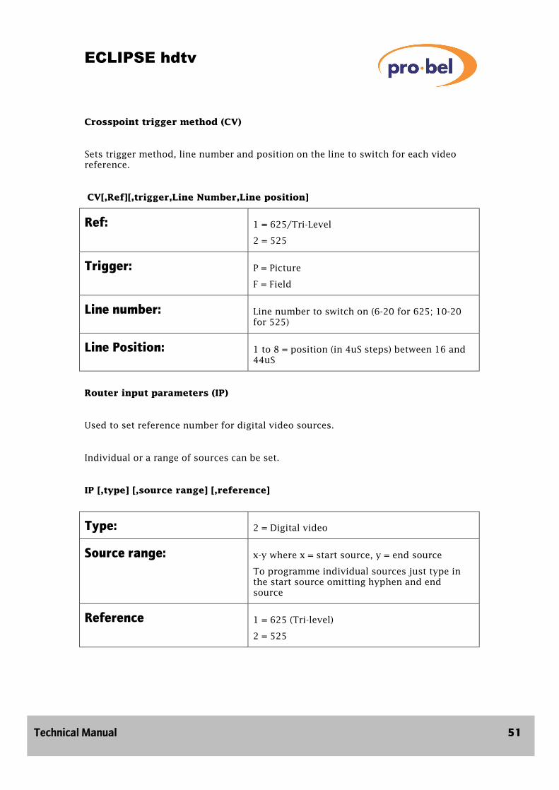
Crosspoint trigger method (CV)
Sets trigger method, line number and position on the line to switch for each video reference.
CV[,Ref][,trigger,Line Number,Line position]
Ref: 1 = 625/Tri-Level
2 = 525
Trigger: P = Picture
F = Field
Line number: Line number to switch on (6-20 for 625; 10-20 for 525)
Line Position: 1 to 8 = position (in 4uS steps) between 16 and 44uS
Router input parameters (IP)
Used to set reference number for digital video sources.
Individual or a range of sources can be set.
IP [,type] [,source range] [,reference]
Type: 2 = Digital video
Source range: x-y where x = start source, y = end source
To programme individual sources just type in the start source omitting hyphen and end source
Reference 1 = 625 (Tri-level)
2 = 525
ECLIPSE hdtv
52 Issue 2
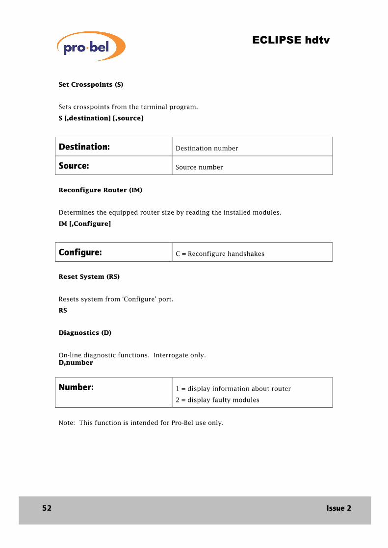
Set Crosspoints (S)
Sets crosspoints from the terminal program.
S [,destination] [,source]
Destination: Destination number
Source: Source number
Reconfigure Router (IM)
Determines the equipped router size by reading the installed modules.
IM [,Configure]
Configure: C = Reconfigure handshakes
Reset System (RS)
Resets system from ‘Configure’ port.
RS
Diagnostics (D)
On-line diagnostic functions. Interrogate only. D,number
Number: 1 = display information about router
2 = display faulty modules
Note: This function is intended for Pro-Bel use only.

ECLIPSE hdtv
Technical Manual 53

ECLIPSE hdtv
54 Issue 2
5 Troubleshooting
The Eclipse router is a complex piece of equipment and although things should not go wrong, this chapter contains some guidelines on what to do if you have any problems. If it is not possible to identify and rectify the problem by following these guidelines, then details of who to contact can be found in chapter 7 -Support information.
Potential problems can be classified at four levels:
• System failure Failure of a PSU or fan
• Major system error It is not possible to set any routes
• System error It is possible to set some routes but others fail
• Minor error There is an error on a single route
The Eclipse router features extensive internal diagnostics via the control system. The frame status leds on the edge of the control module and frame interface module (visible via a light pipe with the unit doors closed) provide immediate pass/fail indication. System failure or major system error faults will be indicated by a red led. System errors will usually also be indicated. Minor errors may be indicated dependent on the nature of the fault. In any instance where the frame status led is red check the faults list on the active control module or frame interface module as the first step in trouble shooting.

ECLIPSE hdtv
Technical Manual 55
5.1 System failure A system failure has occurred when the system is inoperable, only 1 PSU of a main and backup pair is operating or some or all of the fans have failed.
Power failure To detect a power failure check the PSUs as follows:
Yes
Yes
Yes
Check the 5V leds on each module. If they are off, check that the PSU is correctly fittedand pushed home. If it is and the 5V led’s are still off, then there may be a fault on the PSU, and the PSU should be returned
Is the mains led on?Check that the PSU is correctly fitted and pushed home. If it is and the PSU led is still not on then there is a fault on the PSU and the PSU should be returned.
No
No
No
Is the IEC connectorconnected to the correctPSU and powered?
Check the fuse. If required there is a spare fuse in the fuseholder drawer.
Make good the IEC connection. If the problem still persists contact customer support.

ECLIPSE hdtv
56 Issue 2
Fan failure Fan failure has a potentially catastrophic effect on system performance and must be rectified as quickly as possible. Typically an Eclipse router will continue to operate for 2 hours with all fans failed. However beyond this time it is possible that the system will go into thermal shutdown. A system with a single failed fan should operate for longer periods but this cannot be guaranteed. Additionally the long term reliability of the unit may be affected.
To detect a fan failure check the fans as follows:
Examining a fan module Check that the connector from the dc fan to the fan module printed circuit board is correctly fitted and fully engaged. Check that the fan blades rotate freely.
Running the Eclipse router with a failed fan Try to maintain the ambient temperature at a low level. Remove any signal modules not in use to minimise PSU load.
Operating temperatures Relay monitoring provides indication of PSU or fan unit failure. Additionally the control system will indicate an error (and set the frame status led to red) for the following conditions:
• Inlet air temperature > 40°C
• PSU temperature > 80°C
• Internal temperature rise > 40°C
No
No
Fit a backup fan module and examine the failed fan module (see below).
Is the fan power led on?
Yes
Yes
There is a failure on the fan unit. The fan unit should be returned.
Check the fan module is correctly fitted and pushed home. If it is and the fan led is still not on there is a fault on the fan module and it should be returned.
ECLIPSE hdtv
Technical Manual 57
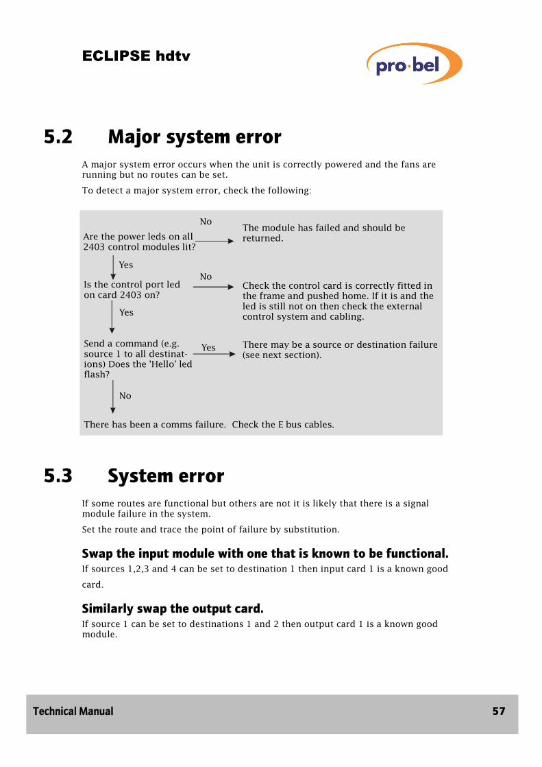
5.2 Major system error A major system error occurs when the unit is correctly powered and the fans are running but no routes can be set.
To detect a major system error, check the following:
5.3 System error If some routes are functional but others are not it is likely that there is a signal module failure in the system.
Set the route and trace the point of failure by substitution.
Swap the input module with one that is known to be functional. If sources 1,2,3 and 4 can be set to destination 1 then input card 1 is a known good
card.
Similarly swap the output card. If source 1 can be set to destinations 1 and 2 then output card 1 is a known good module.
No
No
Yes
The module has failed and should be returned.
Yes
Yes
No
Send a command (e.g.source 1 to all destinat-ions) Does the 'Hello' led flash?
Check the control card is correctly fitted in the frame and pushed home. If it is and the led is still not on then check the external control system and cabling.
Are the power leds on all2403 control modules lit?
Is the control port led on card 2403 on?
There may be a source or destination failure(see next section).
There has been a comms failure. Check the E bus cables.

ECLIPSE hdtv
58 Issue 2
Swap the crosspoint card. Firstly check that the hello led on the relevant crosspoint card blinks when the route is sent by the control system. If it doesn't this suggests a logic failure - try another crosspoint card. If the hello led does blink, there may be a signal path problem on that crosspoint card. Identifying a fully functional crosspoint card is more difficult than input or output cards since each card deals with 2048 signals (64 inputs x 32 outputs. To get a good indication that crosspoint module 1 is fully functional follow this procedure
• Check that source 1 can be routed to destinations 1 to 32 (it may be necessary to move a known good input card into the relevant slot to do this)
• Check that sources 1 to 64 can be routed to destination 1 (it may be necessary to move a known good output card)
5.4 Minor error Where one route has failed or is intermittent the fault may be a failed module as above. However it is equally likely that the problem may not be due to any component failure at all. If one input cannot be routed try physically connecting it to another source or routing it via another path or piece of equipment. Try bridging the route using a BNC barrel. If the signal works via another path this may indicate a module fault or it may indicate that the signal is marginal in performance and is outside of guaranteed Eclipse specification. For one failed output, try the dual of that output or else another destination. Possibly the downstream equipment is not performing correctly.
Check that all modules in the Eclipse system are plugged fully home.
It may be necessary to employ specialised test equipment to carry out further fault finding.
If the reason for the fault cannot be diagnosed contact customer support.

ECLIPSE hdtv
Technical Manual 59
5.5 Diagnostics The control module has a special diagnostics mode which may be useful in tracing faults. This mode is intended for Pro-Bel use only.
Diagnostics mode is enabled by setting DIL switch 7 on the 2403 control module down. In this mode an extra menu is available from the Active system display. Access to this menu is achieved by pressing the down arrow from the database display.
Last crosspoint list Shows the last crosspoint set. Previous crosspoint commands may be shown by using the arrow keys.
Show source Initially shows the destination that source 1 is routed to. Other sources may be selected using the arrow keys.
Other menus These relate to software execution times. Explanation of these is beyond the scope of this manual.
Lastcrosspoint
Up/Down
Up/Down
Up/Down
Show source
Display speed
Display Max Time
Routing seton a source
basis
Last crosspoint
list
Internal use
Internaluse
OK
Cancel
OK
Cancel
OK
OK
Cancel
Cancel
ECLIPSE hdtv
60 Issue 2
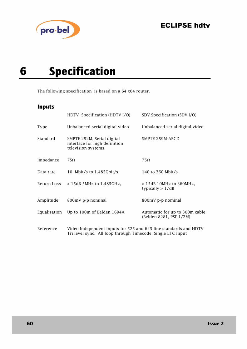
6 Specification
The following specification is based on a 64 x64 router.
Inputs
HDTV Specification (HDTV I/O) SDV Specification (SDV I/O)
Type Unbalanced serial digital video Unbalanced serial digital video
Standard SMPTE 292M, Serial digital SMPTE 259M-ABCD interface for high definition television systems
Impedance 75Ω 75Ω
Data rate 10 Mbit/s to 1.485Gbit/s 140 to 360 Mbit/s
Return Loss > 15dB 5MHz to 1.485GHz, > 15dB 10MHz to 360MHz, typically > 17dB
Amplitude 800mV p-p nominal 800mV p-p nominal
Equalisation Up to 100m of Belden 1694A Automatic for up to 300m cable (Belden 8281, PSF 1/2M)
Reference Video Independent inputs for 525 and 625 line standards and HDTV Tri level sync. All loop through Timecode: Single LTC input

ECLIPSE hdtv
Technical Manual 61
Outputs
HDTV
SDV
Type
Unbalanced serial digital video
Unbalanced serial digital video
Standard
SMPTE 292M, Serial digital interface for high definition television systems
SMPTE 259M-ABCD
Impedance
75 Ω
75 Ω
Data rate
10 Mbit/s to 1.485Gbit/s
140 to 360Mbit/s
Return loss
>15dB 5MHz to 1.485Gbit/s
>13dB 10 Mhz to 360MHz
Amplitude
800mV p-p±10%
800mV p-p±10%
Performance
Clock regeneration
On output
1.485Gbit/s only, Non-reclocked for all other rates
On output
Data acquisition
20mS
20mS
Rise time
<270pS
0.75nS typ
Jitter
135pS, 100m input cable
<0.75nS with >200m input cable
Overshoot/
Undershoot
<10%
Transition timing
Instantaneous, picture or field phased, in vertical interval
Instantaneous, picture or field phased, in vertical interval

ECLIPSE hdtv
62 Issue 2
General (for all frame configurations)
Power
Power consumption Autosensing 90 to 264 Vac 50/60Hz 64 x 64, 300W
Monitoring
PSU monitor Failure alarm relay
Fan monitor Failure alarm relay
Control
Remote control 3 x RS485; Protocol Pro-Bel General Switcher
Configuration RS232, 1 each main and backup controller
Connectors
Power 3 way IEC (with latch)
PSU/Fan monitor 9 Way D type socket
Remote control 9 Way D type socket
Configuration 9 Way D type socket
Mechanical
Size 19 inch rack mounting x 487mm deep (excluding connectors)
Weight 40kg
Enviromental
Cooling Fan assisted, intake and vent at sides
Operating temperature 0 to 40 degrees Celsius
System sizes
64 x 64 7U