hu junsheng - uit
TRANSCRIPT

Faculty of Engineering Science and Technology
Institute of Industrial Engineering
Wireless industrial indoor localization and its application
Hu junsheng
Master thesis in Industrial Engineering - June 2017

Title:
Wireless industrial indoor localization and its application
Date:
01/06/2017
Classification: *)
Author: Junsheng Hu
Student no: 540677
Number of Pages:
Number of Attachments:
Subject Name:
Master’s Thesis
Subject Code:
SHO6266
Department:
Faculty of Engineering Science and Technology
Master Program:
Industrial Engineering
Supervisor:
Gabor Sziebig
Co-supervisor:
External Organization/Company:
External Organization’s/Company’s Liaison:
Keywords (max 10): indoor localization, context-awareness-based service, location-based service, wire-
less sensor, smartphone-based localization
Abstract (max 150 words):
A complete, structural and comprehensive description of indoor localization technology is presented in
this paper. It concluded the basic techniques for distance measurement in indoor localization, the basic
localize principles, the topologies and algorithms which are often used in indoor localization area. Then
how to perform indoor localization with sensors which are available in modern smartphones are detailly
discussed. A topic about how to design an indoor localization based on the previous concluded
knowledge is introduced and an example was given. In the end, the value of indoor localization for in-
dustry is briefly talked.
Table of Contents List of Figures ......................................................................................................................................... 6
1 Introduction ........................................................................................................................................ 10
1.1 indoor localization....................................................................................................................... 10
1.2 project motivation ....................................................................................................................... 10
1.3 contributions of this work ........................................................................................................... 11
2.Location based service ....................................................................................................................... 12
2.1 Context awareness....................................................................................................................... 12
2.1.1 what is context awareness-based service ............................................................................. 12
2.1.2 how context awareness-based service works ....................................................................... 12
2.1.3 location-based service and context awareness-based service .............................................. 12
2.2 Location-based services (LBSs) .................................................................................................. 12
2.2.1 what is LBSs ........................................................................................................................ 12
2.2.2 development of LBSs .......................................................................................................... 13
2.3 Global navigation satellite system (GNSS)................................................................................. 14
2.4 GPS ............................................................................................................................................. 14
2.5 From outdoor to indoor ............................................................................................................... 14
3 Basics of indoor localization .............................................................................................................. 16
3.1 Basic distance detecting techniques. ........................................................................................... 17
3.1.1Time of arrival(TOA) ........................................................................................................... 17
3.1.2 TDOA .................................................................................................................................. 18
3.1.3 Received time of flight (RTOF) .......................................................................................... 19
3.1.4 Angle of arrival (AOA Estimation): .................................................................................... 19
3.1.5 Received Signal Strength (RSS) .......................................................................................... 20
3.2 Positioning Principle ................................................................................................................... 21
3.2.1 Trilateration ......................................................................................................................... 21
3.2.2 Triangulation ....................................................................................................................... 21
3.2.3 Scene Analysis ..................................................................................................................... 22
3.2.4 The proximity ...................................................................................................................... 22
3.2.5 Trajectory ............................................................................................................................. 22
3.4 different positioning Schemes ..................................................................................................... 23
3.4.1 schemes based on special infrastructures............................................................................. 23
3.4.2 signal map or fingerprinting ................................................................................................ 23
3.4.3 Model-Based Techniques .................................................................................................... 24
3.4.4 Device free indoor localization system ................................................................................ 24
3.5 Topologies and ED positions ...................................................................................................... 25
3.5.1 Tracking or positioning........................................................................................................ 25
3.5.2 three topologies .................................................................................................................... 25
3.5.3 layout of external devices .................................................................................................... 26
3.6 Filters and algorithm ................................................................................................................... 27
3.6.1 Gaussian Process Regression(GPR) .................................................................................... 27
3.6.2 Kalman Filter and extended Kalman filter .......................................................................... 28
3.6.3 Particle Filter ....................................................................................................................... 28
4 Smartphone based indoor localization ............................................................................................... 29
4.1 Camera and visible light-based approaches ................................................................................ 29
4.2 Bluetooth low energy (BLE) for indoor localization .................................................................. 30
4.2.1 BLE ...................................................................................................................................... 30
4.2.2 iBeacon ................................................................................................................................ 31
4.2.3 Improve iBeacon based indoor localization ......................................................................... 31
4.2.4 other BLE based indoor localization ................................................................................... 32
4.3 WIFI based indoor localization ................................................................................................... 32
4.3.1 model based indoor localization .......................................................................................... 33
4.3.2 AOA and TDOA based estimation ...................................................................................... 33
4.3.3 WIFI signal fingerprinting approach for indoor localization ............................................... 34
4.4 motion sensor based indoor localization ..................................................................................... 34
4.4.1Reference points ................................................................................................................... 34
4.4.2 Heading (Direction) ............................................................................................................. 35
4.4.3 steps measurement ............................................................................................................... 35
4.4.4 Step Length Calculation ...................................................................................................... 36
4.4.5 position determining ............................................................................................................ 36
4.5 Audio (microphone sensor) based indoor localization ................................................................ 37
4.5.1 audio based TDOA approach ............................................................................................... 37
4.5.2 audio based fingerprinting approach.................................................................................... 38
4.6 magnetic match based approach ................................................................................................. 39
4.7 multi-approach (Crowdsourcing based) indoor localization ....................................................... 39
4.6.1 SLAM with multi-sensors.................................................................................................... 40
4.6.2 Fusion solutions ................................................................................................................... 40
5 Design of indoor localization ............................................................................................................. 41

5.1 the processing of designing the system ....................................................................................... 41
5.2 example of UiT Narvik campus .................................................................................................. 43
5.2.1Need analysis: ....................................................................................................................... 43
5.2.2 source analysis ..................................................................................................................... 43
5.2.3 system decision .................................................................................................................... 44
6. Indoor localization for industrial applications ................................................................................... 44
6.1 Work activity management ......................................................................................................... 45
6.2 Risk management and emergency rescue ................................................................................... 45
6.3 Factory maintenance ................................................................................................................... 45
7. Further work ...................................................................................................................................... 47
7.1 Build a system ............................................................................................................................. 47
7.2 Analysis and improve the system ................................................................................................ 47
7.3 Implement the system design part ............................................................................................... 47
8. Conclusion ......................................................................................................................................... 48
9. References ......................................................................................................................................... 49
List of Tables Table 1 – need analysis of UiT Narvik campus .................................................................................... 43
List of Figures Figure 1 - Mobile LBS revenue forecast, € million (2012–2018)[21] .................................................. 13
Figure 2 - Previous surveys comparison from [26] ............................................................................... 16
Figure 3 – TOA at three positions[30] .................................................................................................. 17
Figure 4- Positioning based on time difference of arrival (TDOA)[32]. ............................................... 18
Figure 5- determine the target by hyperbolics from sensors [30] .......................................................... 19
Figure 6 - Positioning based on AOA measurement[27]. ..................................................................... 20
Figure 7 - trilateration............................................................................................................................ 21
Figure 8 - Triangulation ........................................................................................................................ 22
Figure 9 – fingerprinting procedures ..................................................................................................... 23
Figure 10 - Ten-Ray Model [63] ........................................................................................................... 27
Figure 11- structure of iBeacon system[77] .......................................................................................... 31
Figure 12 - proximity states of iBeacon[78] .......................................................................................... 31
Figure 13 - The acceleration patterns of a pedestrian in stationary and walking states[11] .................. 35
Figure 14 -The influence caused by changing contexts of mobile phone[103]. .................................... 37
Figure 15 – framework for indoor localization UiT Narvik campus ..................................................... 44

Acronyms
LBS Location-based service
GNSS Global navigation satellite system
GPS Global positioning system
UWB ultra-width band
RFID Radio-frequency identification
TOA Time of arrival
TDOA Time difference of arrival
RSS Received signal strength
RSSI Received signal strength index
FCC Federal communication commission
DoD Department of Defense
UiT Norges arktiske universitet (University i Tromsø)
LNA Low Noise Amplifier
RF Radio frequency
VLC Visible light communication
DSSS direct sequence spread-spectrum
RTOF Received time of flight
2-D Two dimensions
3-D Three dimensions
LOS line of sight
MLE Maximum likelihood estimation
PDR pedestrian dead reckoning
IR Infrared
SLAM simultaneous localization and mapping

GP Gaussian Process
k-NN k-nearest neighbor
ITU international telecommunication union
AP Access point
UTD Uniform Theory of Diffraction
ED external device
GPR Gaussian Process Regression
EKF Extended Kalman Filter
UKF Unscented Kalman filter
GS-KF Gaussian sum Kalman Filter
PF Particle filter
PD photodiode
BLE Bluetooth low energy
IoT internet of thing
HAIP High Accuracy Indoor Positioning
SRA Server-Side Running Average
SKF Server-Side Kalman Filter
KFPF Kalman Filter-Particle Filter
MUSIC multiple signal classification
MDI motion dynamic information
BMI building map information
SCS smartphone coordinate system
FFT fast Fourier transform
HPET High Precision Event Timer
NTP Network Time Protocol
NDK Native Development Kit
ABS Acoustic Background Spectrum
VAD Voice Activity Detection
MM magnetic matching
ULP User Location Preference
ICT Communication Technology
SMEs Small and Medium Enterprises
DTW dynamic time warping
LCSS longest common subsequence
ANN neural network
1 Introduction
1.1 indoor localization To locate is one of the basic need of living life since the very beginning of this world while they need
to find their targets. In the beginning, position information of targets is estimated by smelling, sounding,
tracing and seeing.
As the world is developing, everything is becoming increasingly complicated, so does the space where
we live in. Modern people are now dealing with a place with too much information. It is important for
them to get as much as possible details about the environment around and the position of themselves.
In recent centuries, internet and mobile devices become so popular that almost no one can live without
them. Together with billions of programs available in the world, Internet and computing devices are
making life more convenient and world a better place. In the beginning of computer technology, com-
puters are like calculators which needed operators to input all the information and made all the choices
for them, results came with a long-term procedure. Computer science engineers work hard for decades
to make them more intelligent, one of the features is the conception of “context awareness”[1], which
can do some guess for users based on the historical and present information. Among these information,
there is one called location. it contains three main factors: position, time, and objects (who or what).
Therefor location information has a profound meaning. By the help of location information, we can not
only supply services according to where you are, but also according to who you are and when you
require the services. These services are called location based services(LBSs)[2].
A location-based service is a software-level service that uses location data to control features. As such
LBS is an information service and has a number of uses in social networking today as information, in
entertainment or security, which is accessible with mobile devices through the mobile network and
which uses information on the geographical position of the mobile device.
1.2 project motivation Currently most localization service are approached by the technology called Global navigation satellite
system (GNSS). The most famous example of GNSS is the global positioning system(GPS), which was
made to serve the need of military purpose in the beginning[3]. Now it is playing a vital rule in LBSs[4].
It is truly a success in many areas. However, GPS technology has its own limitation[5], which is that it
can only get accurate position when the receiver is outside without any block of the signal.
However, most of the human activities are done in an inside environment[6], therefor indoor localization
became an important subject as an implement of GPS. For so many years, pioneers are dedicated to find
the best solutions. Thousands of articles can be found. Most researchers are focused on wireless signal
approach in which use wireless signals for calculation of the position of target. Currently, there are lots
of wireless standards that are studied. For example, Wi-Fi[7][8], Bluetooth[9][10], ultra-width
band(UWB)[11], radio-frequency identification (RFID)[12] and so on.
Although tons of surveys or articles introduced different work or approaches of current achievement,
there is no one article available gives a systematical and structural view of this area. That adds the
challenges for companies which want to get inside this business or students who would like to do their
researches inside this topic. When a reader read some work related to indoor localization, they feel like
stepped into a huge city without map. This article would like to build the first map for future scholars
and engineers. Though maybe not perfectly detail and complete due to the limit capability of the author.
But everything has its first version. The author hopes this work can be improved in the future and fulfill
its value by guiding more people into this area.
1.3 contributions of this work So, the first contribution is that this is the first article which gives a comprehensive textbook-like intro-
duction of indoor localization technology. This part of work can be seen in chapter 3. It abstractly con-
cluded a systematical structure of indoor localization technological knowledge. As industrial engineer
says:” see the big picture”. After reading this part, it shall help the reader to be aware of what kind of
knowledge they are reading about in the future study. Is it using basic TOA, TDOA, or RSS technology
to measure? Is it using trilateration, scene analysis or proximity to determine the position? Is it device
based or device free system… In the end of chapter 3, a survey of those algorithms which are used to
improve indoor localization systems so that they can get better performances. The first value of this part
is helping people to understand future articles easily. The second value of this part is helping readers to
make decisions when they plan to build an indoor localization system. Which approaches shall they
choose.
The second contribution of this work is a complete analyzing of smart phone based indoor localization.
There are lots of work which introduce smart phone based indoor localization. However, none of them
completely talked about all available approaches. There are some articles talked about hybrid indoor
localization system combing motion sensors and Wi-Fi or Bluetooth[13]. WAIPO[14] utilized Wi-Fi,
camera, magnetic sensor. [15] combined Wi-Fi, Bluetooth, LTE and magnetic sensor. But they ignored
the fact that the modern smart telephones are equipped with light sensor, camera, microphone, motion
sensor, magnetic sensor except Bluetooth, Wi-Fi and GSM. In chapter 4, there will be a complete intro-
duction of modern smartphone based indoor localization. By complete, it does not only mean all the
sensors are introduced, it also means all the possible approaches of each sensor will be also described.
In the end of this chapter, some fusion approaches of these sensors are introduced.
The third contribution of this work is trying to propose a procedure and flow of how to design an indoor
localization system. The most of those research articles follow this pattern: xxx based localization is
good, related work are not good enough, the author made his own contribution by his proposal, experi-
ment test and conclusion. However, no one thinks in a real-life project way, which is when you are asked
to build an indoor localization based on some kinds of need, how to build or how to choose. With the
help of part 3 and part 4, this article will show the way how those knowledges can be used as a reference
for designing the indoor localization system with the example of the authors’ current university campus
in Narvik, Norway.
The remainder of this article is arranged in this way: Chapter 3 gives structural description of indoor
localization technology knowledges. Chapter 4 focus on smartphone based indoor localization. Chapter
5 talks about indoor localization system design. Chapter 6 talks about indoor localization for industrial
applications. Chapter 7 talks about future work and Chapter 8 gives conclusion of this work.

2.Location based service
2.1 Context awareness
2.1.1 what is context awareness-based service One of the reasons why Location based service is so important is because it plays a vital role in context
awareness services. In the beginning of computer usages, it was a tool which needed operators to interact
with computer devices by frequently inputting all the information that is needed for calculations. Inten-
tion of operator can’t be predicted by the machine[16]. In 1994, Bill N. Schilit and Marvin M. Theimer
[17] introduced context as location, identities of nearby people and objects, and changes to those objects.
Context-aware was to sense the “context” defined before.
Nowadays, the common accepted definition of context-aware is from [1]: “A system is context-aware
if it uses context to provide relevant information and/or services to the user, where relevancy depends
on the user’s task.”
2.1.2 how context awareness-based service works According to the definition we introduced before, there can be four steps in context-awareness service:
1) Understand the user: This refers the information collecting and analyzing of the user in order to
get the data of who the user is and his habits or behavior pattern. This indicates what the user
would like to have in a certain context.
2) Understand the service available: This is the survey of services which are available in certain
locations during specific periods of time. It is a resource gathering and service understanding.
3) Match the service with the user’s task: This is the stage when the context-aware service gives
its value by offering the relevant information or service to the user.
4) Update the user’s context: The system can update itself so that it can offer more accurate service
and information.
All these steps are performed now on our personal smart devices such as smartphones, wearable device
or medical monitoring devices. And due to the fast development in embedded system and mobile
phones, context-awareness services have gotten a huge playground to show their values by improving
the daily life experience and have a profound influence on human activities every day and everywhere.
2.1.3 location-based service and context awareness-based service Among the data context-awareness service takes in account, location information is no doubt one of the
most important one. The location the user always is during working time indicates user’s occupation.
Information about where is user on eating time, if user go to some gym and how often, where user travels
and how often, which flight, what kind of hotel and so on indicates user’s lifestyle and preferable.
2.2 Location-based services (LBSs)
2.2.1 what is LBSs LBSs starts from the conception of location. Location information is one of the most important details
in our daily life. According to [18], location can be divided into virtual location and physical location.

The physical location can be further divided into “descriptive locations”, “spatial locations” and “net-
work locations”. In this article, the term location refers to “spatial locations”, which means a single point
in the Euclidean space and position in a two- or three- dimensional coordinates.
So LBSs roughly means offering service to the users based on the user’s spatial locations. In [19], LBSs
were defined as “services that depend on and are enhanced by the positional information of the mobile
device”. Therefor Location based services are those services which are centered on users’ locations and
environments, currently or historically and it is based on mobile devices. For example, mapping, navi-
gation, social networking, property tracking and so on. It is with the user for the whole day from morning
to evening. People can find specific services around and navigate to desired destination. Location based
service can help us to find keys, cars, shops and even friends around by continuously sharing and search-
ing the current locations.
It is a software-level service that take location data into consideration to control features. As such LBS
is an information service and has number of uses in social networking today as information, in enter-
tainment or security, which is accessible with mobile devices through the mobile network and which
uses information on the geographical position of the mobile device.
Location-based services (LBSs) have been evolving in a rapid speed due to that they are playing an
importance role and giving users increasing better experience[20]. The growth of LBS industry is soar-
ing. According to a report from Berg insight Global[21], in North America, LBS revenues are forecasted
to grow from almost US$ 1.8 billion in 2013 to nearly US$ 3.8 billion by 2018.
Figure 1 - Mobile LBS revenue forecast, € million (2012–2018)[21]
2.2.2 development of LBSs The first popularization of LBSs may derive to 1996[22]. In 1996 America federal communication com-
mission (FCC) formally issued a rule that quires all US mobile operators to locate emergency callers
(E-911). At that time, there was around 50% 911 are dialed by mobile telephones and the callers some-
times can’t offer their location information. And this percentage was growing, in order to solve emer-
gency problems quicker and more accurately. E-911 required mobile services suppliers to achieve lo-

calization services with an accuracy within 125 m before the first of October in 2001. And the confi-
dence interval of this localization result had to be greater than 67%. And after that, FCC was keeping
giving higher and higher requirement, thus pushed the development of LBSs from mobile service sup-
pliers.
In Europe, a similar rule was issued in 2000 and it is called E-112. After that many countries such as
Japan and South-Korea also made this kind of rules to push the development of LBSs in their own
territory. LBSs became a global famous conception since then. And there came the spring of it, it is
growing in a rapid speed.
2.3 Global navigation satellite system (GNSS) GNSS indicates systems that give time and position information in a world-wide range. A whole system
contains satellites, ground monitor systems and user’s devices. It can offer real-time, precise time and
location information of objects which are on the earth surface or close to the surface. currently, there
are three GNSS service supplier: American GPS, Russian Glonass and Chinese BeiDou Navigation Sat-
ellite System.
As time goes, GNSS systems play an increasing important role in areas such as ocean exploration, tele-
communication, weather analyzing, oil and gas exploration, traffic navigation and so on. It will influence
our lives in different aspects. GNSS system now is one of the three information technology industries.
It has an unreplaceable meaning on economy, military and political activities.
2.4 GPS GPS was firstly introduced by United States Navy as an experiment to track US submarines which are
carrying nuclear missiles. In the beginning, there were six satellites orbiting the poles, submarines ob-
served the satellite changes in Doppler and then calculated their own location. In the early 1970's, the
Department of Defense (DoD) decided to use satellites to build a robust, stable navigation system. The
first timing and ranging satellite was launched in 1978. Until 1993, a fully operable GPS system with
24 satellites system was completed. Today, GPS is a multi-use, space-based radio navigation system
owned by the US Government. And it plays an extremely important role all around the world in navi-
gation, aviation, surveying, mapping and geophysics, telecommunication and so on. People can hardly
image life without GPS[3]. Owing to the latest technological advances, GPS receivers are able to locate
themselves with an error of 5 meters outdoors[5].
2.5 From outdoor to indoor Statics from America strategy analyze tells that human beings spend around 80% ~ 90% of their time
indoor. And 70%~ 80% of those most important communication activities are done under indoor situa-
tion[6][23]. According to [24], there are around 2.32 billion smartphone users in 2017. And this number
is still increasing. This means there is a huge potential in indoor localization market.
Although GNSS has huge advantages in localization activities, it can be hardly used in indoor localiza-
tion. Normally there is a 20-30 dBm when there is blocks such roofs[25]. This poor performance makes
it hardly possible to work in indoor occasions.
GNSS system, for example GPS, can achieve an accuracy of around 5 meters, which is fair enough in
outdoor applications. However, it does not work in an indoor situation where 5 meters can mean a dif-
ferent room or unit. In [26]the author made an argument that suppose the GPS can have a same good

performance as outdoor situation. The 5-meters error may mislead the program to think object is in a
totally different another shop, and to offer a totally wrong LBSs notification and service. This mistake
gives users unpleased experience instead of convenience. This is not what LBSs aim to.
Therefor there must be an implement way to get location and time information under the roof with a
better accuracy performance.
There are some researchers proposed ways to help GPS working inside buildings. For example,
Kerem[5] proposed to use repeaters in indoor environment. They consist of a directional antenna for
receiving a non-overlapping set of GPS satellites, a LNA (Low Noise Amplifier), a power amplifier for
compensating the antenna and cable losses, and a transmitting antenna for re-radiating the amplified
GPS signals.
Paul[23] analyzed a technology called assisted GPS (A-GPS) which was intended to give GPS a better
performance in indoor applications, it still can’t meet our requirement. According to the study conducted
in [23], it can just ensure an accuracy within 100 meters. This is impossible for most of the indoor
location cases.

3 Basics of indoor localization In one of the newest survey about indoor localization [27], the author claimed that it contains all the
indoor localization research area and gave comprehensive schemes. They made a whole diagram of
comparison to prove that.
Figure 2 - Previous surveys comparison from [26]
However, the survey is not complete and is not comprehensive enough. For example, those approaches
based on the motion sensor[28] which is built in smart telephones, they ignored the fact there are ap-
proaches which are “device-free”[29]. The authors claimed they gave comprehensive schemes. Alt-
hough they introduced AOA, TOA, RSS-based, fingerprinting approaches and then RF platforms such
as Bluetooth, Wi-Fi, Visible Light Communication, sound-based Technologies and others are described.
However, they ignored the fact that fingerprinting has to use the knowledge of RSS or AOA or TOA,
and these three are basics for other approaches such as Bluetooth, Wi-Fi or VLC. They are hardware
independent. Fingerprinting can be also used for a lot of other approaches. Most of the surveys available
in the database can’t give a structural or systematical view of these techniques.
This chapter tries to introduce indoor localization with a comprehensive structure and levels. In 3.1, it
will introduce those basic approaches such as TOA, TDOA, AOA, RSS-based techniques. These tech-
niques are talked very often when it comes to indoor localization. Actually, AOA, TOA can also be used
for outdoor localization applications. They are the basic way to measure distances with the help of sig-
nals.
In 3.2 the basic principles will be introduced. There are distance-based approaches despite how the
distances are achieved, angel-based despite how the angles are achieved, scene analyzing based on fin-
gerprinting despite what kind of finger or signature and approximate which just try to ensure the target
is in some defined space unit despite what method are used.
In order to achieve indoor localization, most researchers would require the target to carry some devices.
The system locates the devices instead of human. they are called device-based approaches. The study of
[27] are put under the device-based category. However, there are researchers working on device-free
indoor localization systems which does not require the target to carry any devices.
In the device-based scheme, the best device is our smart telephone which people like to take with all the
time. So instead of talk about those massive researches. This article would like to narrow the study area
into smart telephone based indoor localization and in the future how this can be used in industry area.
In the last of this part, after all the categories are introduced. There is one special detail will be talked.
That is the topologies of the system. This is a must-think and always-ignore problem that we have to
consider when design a indoor localization system.
3.1 Basic distance detecting techniques.
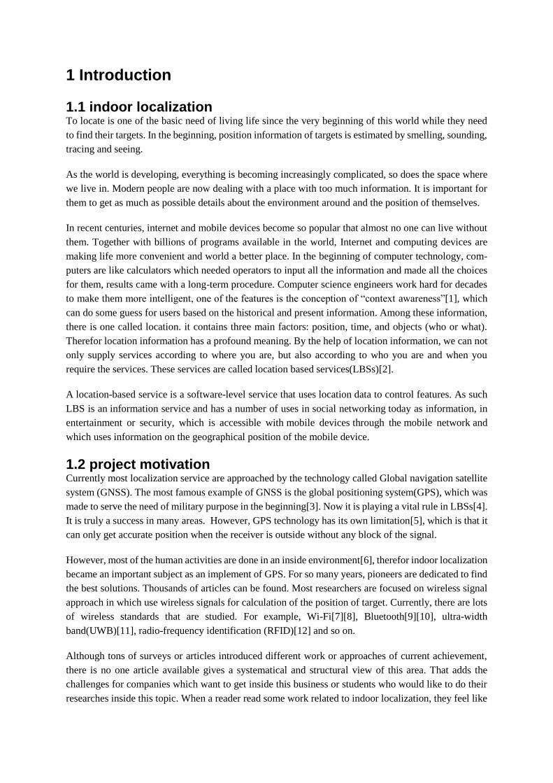
3.1.1Time of arrival(TOA) As we all know, if the speed of travelling can be mathematically described, then the distance can be
calculated as
0
( )TOA
D speed t dt (1)
Where ( )speed t
represent the instantaneous velocity at time 𝑑𝑡. In this application,
Figure 3 – TOA at three positions[30]
( )speed tis the propagation time of radio signal through the measured space. As is shown in Figure 3,
the distances between sensors and the target can be determined when TOA are measured. Then the joint
point of circles determined by sensors and distances is the position of the measured target. In order to
get a determined single joint point, there must be at least 3 circles, which indicates at least 3 sensors are
needed in a 2-D positioning system.

In general, direct TOA results in two problems. First, as the RF signals travels in the space with a speed
close to light, therefore a slice error in the measurement of the TOA can lead to a huge error in locali-
zation result, there must be extremely precise, high speed timer and clean code (execution time of the
program code can’t be ignored in this kind of situation.) for the measurement device. All transmitters
and receivers in the system have to be precisely synchronized. Second, a timestamp must be labelled in
the transmitting signal in order for the measuring unit to discern the distance the signal has travelled.
TOA can be measured using different signaling techniques such as direct sequence spread-spectrum
(DSSS) [31] or ultra-wide band (UWB) measurements [11].
3.1.2 TDOA As we discussed before, TOA has high requirement of hardware and software on not only sensors but
also mobile devices. It is not practical for our telephones. So in order to eliminate the requirement of
mobile device, an improved method called TDOA was developed.
Figure 4- Positioning based on time difference of arrival (TDOA)[32].
Instead of measuring the TOA on different sensors, the difference between arrival time will be used to
determine the relative position of the signal transmitter, which is our mobile devices. For example, if
sensor 1, sensor 2 and sensor 3 receive a signal at t1, t2 and t3 respectively. Due to the fact at we do not
know when exactly the signal was sent, we can know the |t2 – t1|, |t3 – t1| and |t2 – t3|
At the same time the distance differences between sensors are determined by[33]
2 2 2 2 2 2
, ( ) ( ) ( ) ( ) ( ) ( )i j i i i j j jR x x y y z z x x y y z z (2)
where (xi , yi , zi ) and (xj , yj , zj ) represent the fixed receivers i and j; and (x, y, z) represent the coor-
dinate of the target[33][34].
,0
( )i jt t
i jR speed t dt
(3)
So there will be three equations
1 2
3 2
1 3
2 2 2 2 2 2
1 1 1 2 2 20
2 2 2 2 2 2
3 3 3 2 2 20
2 2 2 2 2 2
1 1 1 3 3 30
( ) | ( ) ( ) ( ) ( ) ( ) ( ) |
( ) | ( ) ( ) ( ) ( ) ( ) ( ) |
( ) | ( ) ( ) ( ) ( ) ( ) ( ) |
t t
t t
t t
speed t dt x x y y z z x x y y z z
speed t dt x x y y z z x x y y z z
speed t dt x x y y z z x x y y z z
(4)
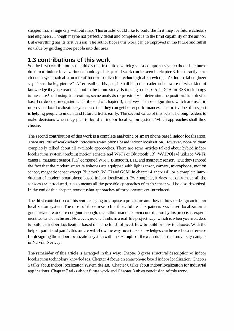
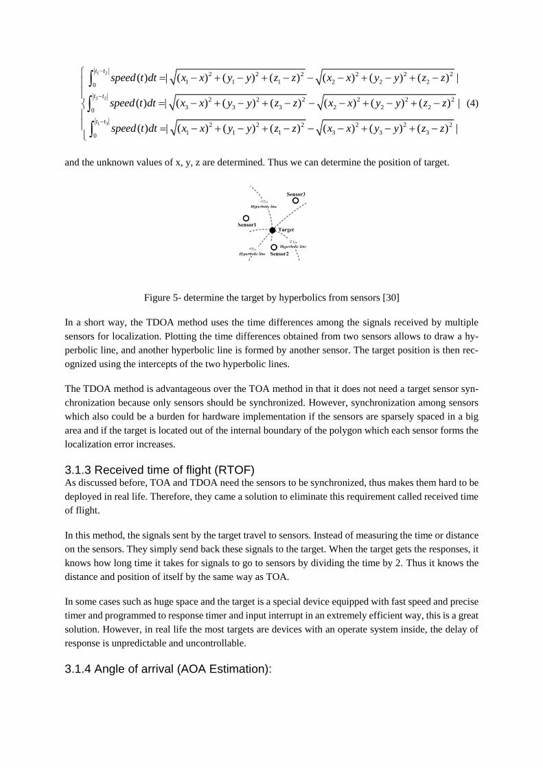
and the unknown values of x, y, z are determined. Thus we can determine the position of target.
Figure 5- determine the target by hyperbolics from sensors [30]
In a short way, the TDOA method uses the time differences among the signals received by multiple
sensors for localization. Plotting the time differences obtained from two sensors allows to draw a hy-
perbolic line, and another hyperbolic line is formed by another sensor. The target position is then rec-
ognized using the intercepts of the two hyperbolic lines.
The TDOA method is advantageous over the TOA method in that it does not need a target sensor syn-
chronization because only sensors should be synchronized. However, synchronization among sensors
which also could be a burden for hardware implementation if the sensors are sparsely spaced in a big
area and if the target is located out of the internal boundary of the polygon which each sensor forms the
localization error increases.
3.1.3 Received time of flight (RTOF) As discussed before, TOA and TDOA need the sensors to be synchronized, thus makes them hard to be
deployed in real life. Therefore, they came a solution to eliminate this requirement called received time
of flight.
In this method, the signals sent by the target travel to sensors. Instead of measuring the time or distance
on the sensors. They simply send back these signals to the target. When the target gets the responses, it
knows how long time it takes for signals to go to sensors by dividing the time by 2. Thus it knows the
distance and position of itself by the same way as TOA.
In some cases such as huge space and the target is a special device equipped with fast speed and precise
timer and programmed to response timer and input interrupt in an extremely efficient way, this is a great
solution. However, in real life the most targets are devices with an operate system inside, the delay of
response is unpredictable and uncontrollable.
3.1.4 Angle of arrival (AOA Estimation):

Different from the previous three methods, AOA try to figure out the distance in a geographic way. This
will of course solve the problem of timer and response delay.
Figure 6 - Positioning based on AOA measurement[27].
In this method, the receivers are equipped with angle sensors which can measure the angles of where
the signals come from. After the receivers sending these angles to the sever, the server can draw lines
from these receivers and the intersection is the relative position of the target. As shown in Figure 6, in
2-D positioning system the position can be determined by at least two receivers. This is better than the
previous methods which require at least 3 receivers.
However, despite the requirement of the antennas of the hardware. Targets’ movement effects the results
of the measurement. The accuracy is limited by the shadowing, by multipath reflections arriving from
misleading directions, or by the directivity of the measuring aperture[35].
3.1.5 Received Signal Strength (RSS) The previous discussed techniques are based on one condition which is line of sight (LOS) which indi-
cates that the signal can directly go from transmitter to the receiver. However, this condition is hard to
be meet due the complex indoor environment. An alternative is to measure the strength of the received
signal and calculate the distance base on the signal propagation model[36]:
0
0
( )( ) ( ) 10 *log( )
( )
nW WAF nW CRP R P R n
C WAF nW CR
(5)
where R represents the distance between the transmitter and the receiver, R0 is a reference distance,
p(R) and p(R0) the signal strength received at R and R0 respectively, nW represents the number of
obstacles (walls) between the transmitter and the receiver, WAF means the wall attenuation factor, C is
the maximum number of obstacles between the transmitter and the receiver, and n is the routing attenu-
ation factor which could be determined by both theoretical and empirical calculations[36].
This equation (5) can be simplified to path loss model as:
0 10
0
10 logd
PL PLd
(6)
where PL is total path loss at distance d, 0PLis total path loss at a distance 0d
, is path loss exponent
and is variable accounting for variation of the mean and is often referred to as shadow fading[37].

RSS value is now can be read in both mobile devices and routers despite Bluetooth platform or Wi-Fi
platform. Therefore, it one of the most popular tool for indoor localization. Apple’s iBeacon system,
which is currently the only commercialized system is also based on this method.
There are two ways to utilized RSSI based technique. They are pass loss model based localization and
fingerprinting based localization. The former one try to calculate the distance according to equation (6)
[37]while the later one try to build a signal map and estimate the position by matching the current meas-
ured RSSI the RSSI value stored in the signal map[38][39][40].
3.2 Positioning Principle In [41] the author introduced four principles used in building positioning systems. They are Trilateration,
Triangulation, Scene Analysis and Proximity. These principles used can provide a fast calculation of the
position. It can also provide a good accuracy depending on the system architecture too[42]. In this paper,
trajectory principle is added to be fifth one due to that pedestrian dead reckoning becomes one of the
hot topics in indoor localization area.
3.2.1 Trilateration As illustrated in Figure 7, the trilateration based positioning algorithm uses three fixed non-collinear
reference nodes to calculate the physical position of a target node (in 2-D).
Figure 7 - trilateration[42]
Based on the coordinates of three reference nodes: 1 1 2 2 3 3( , ), ( , ), ( , )A x y B x y C x y , and the correspond-
ing distances from each reference node to the target node: 1 2 3, ,R R R, we can obtain the following equa-
tions:
2 2 2
1 1 1
2 2 2
2 2 2
2 2 2
3 3 3
( ) ( )
( ) ( )
( ) ( )
x x y y R
x x y y R
x x y y R
(7)
where (x, y) denotes the (unknown) coordinates of the target T.
TOA, TODA and ROTF belong to this category.
3.2.2 Triangulation When AOA measurements are available, position of target can be calculated. In this approach, angles
can be measured instead of distances. Since the distance between nodes are known in most situations,

there just need two angles to figure out the position. Therefor just 2 nodes are enough. As shown in
Figure 8, where A and B represent reference nodes, after obtaining the angles 1 , and 2 , the physical
position of T (representing the target to be located) could then be calculated based on the predetermined
coordinates of the reference nodes.
Figure 8 - Triangulation[34]
3.2.3 Scene Analysis Scene Analysis is another principle of positioning in which special information is collected in specific
position and this position of target can be decided when it get the same special information. The most
approach uses scene analysis is fingerprinting. A fingerprint is the signature that differentiates the scene
from other ones [43]. It is the unique feature or a few features of the location. It works by building a
feature map of the location and stored in the databased. When the target reached a location and the new
collected feature matches a stored feature in the data based, a location will be matched.
3.2.4 The proximity In lots of cases, the requirement of the system is not to know the exact spatial location, it need to identify
the target in a known set of zones, for example, room, section, or within 5-meters around. In [44], the
author developed an API meant to support applications for which the exact position of a mobile terminal
is not a primary requirement, but it suffices to identify a proximate zone. It is mainly used in Radio
Frequency based systems. For example, apple’s iBeacon[45] can be considered as one of this. Actually,
fingerprinting can be also regarded as a proximity approach with a finer accuracy. It can be said that
most scene analysis is some kind of proximity,[46] used acoustic sound information in some special
places as basis for indoor localization. One of the popular ways to achieve proximity is Maximum like-
lihood estimation (MLE).
3.2.5 Trajectory Different from the previous ones, this principle is not based on the signal measurement. Instead, it based
on the movement of the target. There must a start point of the system. When the target have movement
action, the distance and direction information can be added to the start-point to form the trajectory, and
thus the position of the target can be known. This is especially useful for vehicles wheelchair or trolley
localization. When it comes to walking people, there is an approach called pedestrian dead reckon-
ing(PDR) which is one of the hot topic in indoor localization.
3.4 different positioning Schemes
3.4.1 schemes based on special infrastructures In the beginning of the work, while mobile telephones were not so powerful as today, people are focused
on approach which required special infrastructures. For example, infrared (IR) was used by Active
Badge[47] to perform localization. Ultrasound devices was deployed by solutions such Cricket [48] and
Active Bats to localize in the indoor environment and mobile devices. Recently, RFID became a hot
topic and attracted many researchers. Solutions such as LANDMARC[49] and so on are very attractive.
However, firstly, these solutions require these special devices make an extra burden for targets. In real
environment, it is easy to forget these devices at home or in the car or on the desk. Or in some occasions,
target refuse to carry them. So they may not assure a real-time reliability. Secondly, these systems re-
quire significant fund and effort which may hinder the development of themselves.
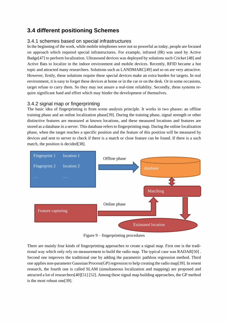
3.4.2 signal map or fingerprinting The basic idea of fingerprinting is from scene analysis principle. It works in two phases: an offline
training phase and an online localization phase[39]. During the training phase, signal strength or other
distinctive features are measured at known locations, and these measured locations and features are
stored as a database in a server. This database refers to fingerprinting map. During the online localization
phase, when the target reaches a specific position and the feature of this position will be measured by
devices and sent to server to check if there is a match or close feature can be found. If there is a such
match, the position is decided[38].
Figure 9 – fingerprinting procedures
There are mainly four kinds of fingerprinting approaches to create a signal map. First one is the tradi-
tional way which only rely on measurement to build the radio map. The typical case was RADAR[50] .
Second one improves the traditional one by adding the parametric pathloss regression method. Third
one applies non-parameter Gaussian Process(GP) regression to help creating the radio map[39]. In resent
research, the fourth one is called SLAM (simultaneous localization and mapping) are proposed and
attracted a lot of researchers[40][51] [52]. Among these signal map building approaches, the GP method
is the most robust one[39].
Offline phase Fingerprint 1 location 1
Fingerprint 2 location 2
… ….
Fingerprint n location n
database
Feature capturing
Matching
Estimated location
Online phase

There are few ways to decide the location of target, the most popular one is to compare the real-time
captured feature with the data in the database by k-nearest neighbor (k-NN) algorithm[7][53]. Other
approaches to match based on the way how the signal map was built are introduced in [39] and [40].
One fact that most researchers haven’t paid attention is the time window of fingerprinting. That is how
often to scan the signals. Due to the fact that different RF signals work in a different frequency, they
may have different properties. And if the target is moving, the movement rate and distance have to be
taken into consideration and the signal. Work which is done by Ramsey Faragher and Robert Harle [54]
showed that Bluetooth fingerprinting has higher requirement on time window while it need less scan
period.
3.4.3 Model-Based Techniques Model-Based approaches are used for many kinds of dynamic systems for prediction, controlling or
calculating. Model can be divided into three categories: white-box models, black-box models and grey-
box models[55]. White-box models are those models we theoretical know the relationship between the
know and unknow parameters, for example the RSS free space loss model. The black-box models are
those kinds model we obtained from experiment, however there is no mathematical expression, for ex-
ample the fingerprinting approaches is black-box modeling. The grey-box models those we partly know
the model, it’s a situation between white-box and black-box.
Model-based approaches is that the system tries to localize the target by the RSS value measured in real-
time. It has a significant value because it can work without access to other sensors and it does not require
so much labor work like fingerprinting approach does. These benefits attracted a lot of researchers’
effort. Research from [8] showed it can offer a result similar to existing other methods. Researches from
[56] showed that by model-based localization method can be built even without the cooperate of the
access points[8].
In the previous sections, the model to calculate RSS value from specific distance was introduced. Ac-
cording to the trilateration principle, a location can be decided if there are three known distances. So
there are many researchers try to use this model to predict or calculate the RSS value on different points,
and use this to build the map or determine the location of target in real-time. It can significantly reduce
the measurement from fingerprinting approach. Since RF propagation characteristics vary widely, the
model parameters would have to be estimated for each indoor space in question.
There are mainly two well-known propagation models: free space path loss and ITU(international tele-
communication union) models[57]. All model-based approaches have to solve two problems. How to
decide the parameters and how to deal with the interferences from other objects. Simon Yiu and his
colleagues [39] used a fusion method combined pass loss model with fingerprinting. Other researchers
try to give model-based approaches self-adaptive capabilities[9][8].
3.4.4 Device free indoor localization system In the previous discussed schemes, they have a same character that we all assume the target is carrying
the mobile device. By locating the mobile device, we can locate the target person. Is that possible to
achieve the goal when the person is not carrying the device? The answer is positive. There are research-
ers dedicated on those kinds of system called device-free techniques. It is called device-free[58] is be-
cause it does not require the target person to carry any device. However, the indoor environment still
need APs (Access points) or Bluetooth signal transmitters to cover the area with RF signals and signal
receivers to measure the changes of the RF. However, there is a lot of mathematical challenges.
Device free indoor localization was introduced in [59][58]. Device-free localization sometimes can be
regarded as a subset of model-based approach and also can be called as ray-tracing. The basic of this
idea is that our human body has specific influence on RF signals. Work in [60] showed that the human
body can be modeled as metallic circular cylinder when consider its influence on RF signals. Before
this system can work, fixed APs and measurement points should be set, then the RSSI values in the field
should be measured or calculated by the model-based approaches. When the human enters the environ-
ment of interest, the influence can be modeled with Geometric Optics augmented with the Uniform
Theory of Diffraction (UTD)[59][60].
Due to the principle that this approach depends on the human influence on the RF signals, the human
body should be put between APs and measurement points. Research showed that in this kind of case,
wall mounted APs is a better solution than roof mounted. Roof mounted design has a better opportunity
to have LOS conditions. And due to the fact that the higher the radio frequency is, the better it goes
through the objects, that leads to a less significant change in the signal. Device-free approach works
better for those low frequency signals[29].
3.5 Topologies and ED positions
3.5.1 Tracking or positioning A localization system can be divided into tracking and positioning system depend on who is the initiator.
When the initiator is an external party, the system is a tracking system or passive system. The passive
system is that the user does not intended to be localized or they are intended to be localized but don’t
give effort to help this work. For example, emergency rescue, iBeacon advertisement or customer be-
havior analysis systems. In this kind of system, the designer can’t expect the user to hold the device on
hand and open specific app or even signals. For example, a lot of people may turn off Bluetooth function
to save smartphone battery life. And due to that the ios system has a strict control of the Wi-Fi system,
a lot of system which depend on monitoring the Wi-Fi signals may not work. This system may have
issue with human privacy, therefor there is lots of challenges.
When the initiator is the user, this system is called positioning system or active system. The active
system, on the other hand, is that the users themselves want to be localized. The best example is navi-
gation system. They need to hold the device and run specific app in order to get the service. The customer
can be asked to open some settings in the device to help improve the performance and accuracy. Because
there is a app work in the localization system on the device, it offers huge amount of possibilities. How-
ever, power consumption may be a drawback and the system designer need to carefully consider about
it.
3.5.2 Three topologies There are three different system topologies for positioning systems[33].
(1) Remote positioning: In this system, the fixed devices or infrastructures measure the signals
(AOA, TOA, TDOA or RSSI) and report to a center server. The signal available is limited by
the measurement devices. Powerful and expensive devices is possible to be used. In the server,

a special program handles the data and give the location based on the required principles and
different approaches. Passive localization is remote positioning.
(2) Self-positioning: In this system, the signals or other information for deciding the location are
measured by the user’s device. And the device computes the location based on different princi-
ples and approaches. The signals available is limited by the device, and the device may have a
limit computation capability. But it is possible to use other approach such as magnetic sensor,
motion sensor even microphone in the device.
(3) Indirect-positioning: this is a combination of the previous two topologies in order to overcome
the limit of mobile devices. In this system, the mobile device can measure all the localization
related information, and send them to a server. And at the same time, if it is possible, the signals
from the mobile devices can also be measured by other devices. The server is in charge of com-
puting the location and send the location to back to the mobile devices. An indirect-positioning
system is a system which the mobile device measures the information but doesn’t computer the
position. But the mobile device gets the location from a server.
3.5.3 layout of external devices Here the external device (ED) is used instead of access point, because in different approaches, the ex-
ternal device may refer to different things. In visual light communication based approach it refers to
lights, in acoustic sound based approach it may mean sound resources, in Bluetooth based approach it
may be iBeacon device or other Bluetooth devices. In a special cased called crowd sourcing, the ED is
other mobile devices. Some of the mentioned ED is not controllable, for example, sound resource and
other mobile devices. In those EDs that we can control, different design may lead to different perfor-
mance.
ED plays a very important role in indoor localization system because it is the biggest hardware system
in indoor localization. And this is also one of the limits of indoor localization. For example, Array-
Track[61] has already achieved a 0.1 meter accuracy, but the multi-antenna router it used is expensive
and not popular, so it can hardly be accepted. Visual communication system need to adjust the whole
light system of the architecture, this also has a high cost. This is the reason why the Wi-Fi and LBE are
the most popular approach. The Wi-Fi can deploy the current exist APs everywhere, which almost
doesn’t add any further cost. IBeacon devices is relatively cheap[45], but is still not be widely used yet.
In the topic about model-based localization and device-free indoor localization, we talked about the
model of signal free space loss[57] and human-scattering effects[60]. This is what is happening all the
time between EDs and mobile devices. In a device-free system, as it was said, LOS is the worst situation.
So it is best to put the signal emitter and receiver in positions where human can mostly be between them.
That’s why wall mounting is the best solution. We may think it is better to use roof-mounted structure
in mobile device-based approach and deploy as dense as possible. However, researches give a different
result.
Work done in [62] showed that the accuracy can be increased by adding the amount of APs in the
beginning, however, due to the increasing channel interference, the improvement will stop when it
reaches a specific number. And this work also suggested to use orthogonal channel allocation, by this
way, the accuracy can improve 10% and can reach the best accuracy with 15 % less APs than using ad-
hoc and ascending channel allocation.
When consider about how to mount APs, work done in [29] showed a surprising result: roof-mounted
APs design is not better than wall-mounted design. Although wall-mounted design may have a low
possibility of LOS and higher chance to reduce the RSS due to attenuation, while roof-mounted design
has a higher chance to meet LOS condition, their experiment showed that line of sight is not the most
important factor in RF signal measurement.
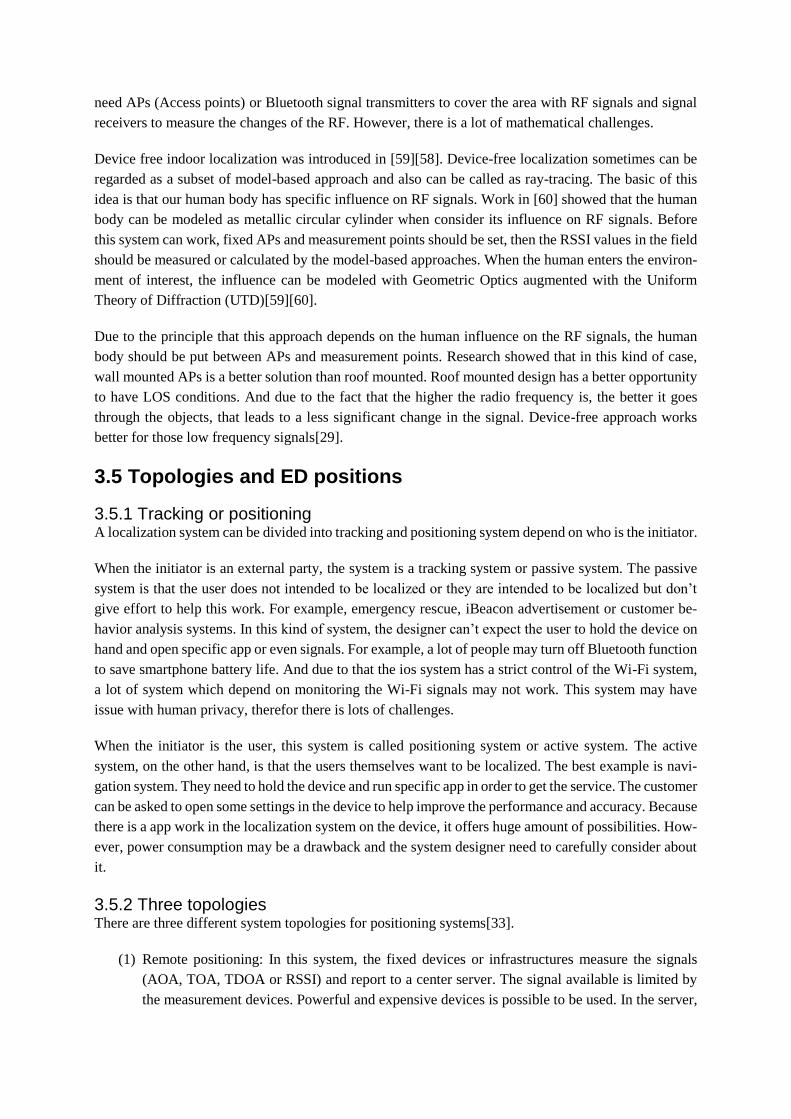
3.6 Filters and algorithm The challenges of indoor localization are the complicated indoor layout and moving objects such as
human, this makes line of sight almost impossible between sensors and targets all the time. The RF
signals can get through between targets and sensors despite the LOS challenge. However, it has a phe-
nomenon called multipath propagation. That is the receiver will not get only one or two signals from
the sender at once. The signal spreading on all the directions and reflected by objects and then some of
the reflected signals go to the receiver with the main one if it is not blocked. And the signal is travelling
in environment with human amount of noise.
Figure 10 - Ten-Ray Model [63]
This forces an unfortunate trade off that most existing RF-based indoor localizations make: either model
this hard-to-predict pattern of multipath fading, or leverage expensive hardware that can sample the
wireless signal at a very high rate. Most of the researchers choose the former one. That’s why they used
very complicated model-based, fingerprinting with huge effort work, approximate to get a not precise
result. Dealing with this challenge is not only the work for those work on indoor localization, also the
work for signal processors and mathematics.
In this section, some mathematical approaches and how they are used to improve the performance will
be introduced. Details about the mathematical knowledge will not be described, but articles about them
will be recommended.
3.6.1 Gaussian Process Regression(GPR) Gaussian process regression is a popular way to estimate or predict the unknow variables. One of the
most famous and well accepted research to use Gaussian Process (GP) to estimate location was done by
Brian Ferris[64]. His research showed that GP can offering continuous locations estimation in a wide
range with an ability to correct uncertainty handlings.
In Ferris’ later woke in [40], he proposed a Gaussian Process latent variable model to solve the Wi-Fi
SLAM problem, although his result didn’t show a good accurate, but comparing to other SLAM or
fingerprinting approaches, his approach was extremely effective. And this can be a good implement for
other work to improve the performance.

3.6.2 Kalman Filter and extended Kalman filter Details and principles of Kalman filter can be read from [65], it will not be repeated here. The function
of Kaman filter is to eliminate the noise caused by measurement and process, and use an estimator to
estimate the state value of linear systems. But there is precondition, which is the average of noise should
be zero.
When it comes to nonlinear system, an extended Kalman filter can be used. Sometimes, the application
is not only to measure, but also to predict, then there came a modified version called Kalman smoother.
It can be shown that the Kalman filter minimizes the variance of the estimation error. A complementary
Kalman filter is an easy way to integrate several sensors measurements in a Kalman filter because the
internal structure of the filter is not changed[66].
3.6.3 Particle Filter Kalman Filter works great in linear system. When it comes to non-linear system a lot of upgraded ver-
sion are proposed such as extended Kalman Filter (EKF) [67], unscented Kalman filter (UKF) [68],
Gaussian sum Kalman Filter (GS-KF) [69] and so on. But their performance in non-linear system is still
not satisfying[70].
The particle filter (PF) is a classical object tracking algorithm for non-linear and non-Gaussian systems,
which is an approximation of the optimal sequential Bayesian estimation via Monte Carlo simula-
tions[71]. It works better than Kalman Filter in some aspect when the problem is non-linear. Or some-
times, the Kalman Filter can be used to measure the linear aspect of the problem and PF can be used to
estimate the whole system[72]. More details about PF can be read from [70][73][71], it is not repeated
here.
4 Smartphone based indoor localization As we have discussed about device-free technique, special infrastructure based schemes. I believe the
practical approach is to use device-based technique with our smart mobile telephones. There are mainly
two RF signals which can be used for indoor localization. They are Bluetooth and Wi-Fi signal. A part
of researchers is dedicated in one of these two platforms and they give their arguments. One part of
researcher thinks it is better to combine them to achieve a better result. However, I don`t think we should
limit ourselves since there are other information available on the smartphones. For example, the iPhone
7 is equipped with three-axis gyro sensor, accelerometer, proximity sensor, ambient light sensor, ba-
rometer. As the competition goes between smart telephone companies. These sensors will be equipped
by all the smart phones and there can be more sensors.
In this part I would like to introduce pioneer work on indoor locations based on these sensors. Different
from other surveys, instead of pointing out their problems, I would like to find out their positive sides
for future choose when we need to design an indoor localization system.
Smartphone based indoor localization can be divided into two applications: tracking and navigation.
Tracking is passive which means telephones are stored in the pockets or bags while navigation is active
when telephones are hold on users’ hand with app display on and special app is running.
It is possible to employ all the possible sensors when in a navigation application where the users are
willing to assist the system to get a better accuracy. The system can ask the user to turn on Bluetooth,
give access to the camera or microphone and so on. However, in tracking application it is possible that
the Bluetooth is turn off, camera can’t work for indoor localization when it stays inside the pocket or
bag.
Although the process ability and cache of modern smart phone are improved at a quite surprising speed,
some of them can almost beat normal laptops, they are limited by the battery capacity. Therefor, power
consumption has to be taken into consideration when design a smart phone based indoor localization
system. Sampling frequency, computation has to be reduced while chasing the best performance.
There are mainly three smart phone systems. They are ios, android and windows phone. The ios system
is quite closed and completely controlled by apple. As a side effect of that, some approach may not work
on this platform, for example, Wi-Fi fingerprinting.
4.1 Camera and visible light-based approaches As a human, our first experience of localization is to use our eyes. Using camera is a good imitation.
Since this chapter is talking about using sensors on the smartphone, the approaches which uses camera
on the wall will not be talked her. The system her is to use the camera or light sensor on telephone to
locate itself. It is a positioning system. The main idea in the back of this approach is a technology called
visible light communication(VLC) [32].
In [74], author introduced a smart LEDs based localization system by using the visible light from light
systems called Epsilon, which an available in almost all the indoor environment. It uses the trilateration
principle which means at least three anchors are needed in order to achieve position determining. The
distances between the target and anchors are calculated by RSS-based technique which based on the
RSSs from the light which was sensed on the smart telephone. Different anchors are identified with
different emitting frequencies which have to be over 200 HZ in order to avoid flicker to human eyes and

stay away from sound frequency (50/60). But the sampling frequency of sensors on the smart phones
are not so high, several hundred HZ. So the available designed frequency is limited in this range. This
system makes use of the light infrastructure of buildings or other indoor space, reduces the requirement
of radio frequency devices and signal interference, achieved a sub-meter accuracy. This system requires
devices in a light of sight (LOS) scenario and have at least three LOS LED anchors. Furthermore, for
those situations such as telephones in the pocket or blocked by bodies or other objects, it can hardly
work.
In [75], the author offered an improved visual localization system with image processing technology. It
deploys the camera on the smart telephone and the around infrastructure: LEDs. The basic approach is
to take pictures with several led anchors and the target inside. The anchors are configured into different
frequencies. So that the system can know where the anchors are and by using image processing technol-
ogy, distances between the object and anchors are got. So can the system know the exact position of
target. With an enough number of anchors in the picture, Luxapose is able to achieve a 10-cm accuracy
indoor positioning. What is more from this system is that, the system can figure out the orientation
information which not available in lots of solutions. By comparing the coordinate axis in the image
with the ground truth, Luxapose is able to determine the mobile’s orientation to an accuracy of 3◦. A
similar system developed by Philips was deployed at Carrefour[76].
Due to the limit of LOS and benefit of accuracy, it is great for those applications which users would like
to take it outside pocket such as indoor navigation, traveler guiding and so on.
In [32], plenty of VLC based positioning systems are introduced. And a lot of them provide much better
accuracy then other approaches. However, Luxapose is based on windows phone system. Android and
apple IOS does not give the API to get access to full camera control. Their visual light approaches are
based on a special device photodiode (PD) which is not integrated inside smart telephones yet. So as
shown in the illustrating video of Philips VLC based indoor localization system, camera-based ap-
proaches are more practical.
4.2 Bluetooth low energy (BLE) for indoor localization
4.2.1 BLE In recent years, low energy wireless communication technologies are one of the hot topics due to the
coming internet of thing (IoT). ZigBee was regarded as the best option of future industrial wireless
communication standard. However, it shows that it has its own problems. At the same time, there came
a new standard of Bluetooth, which named as Bluetooth low energy (BLE) aiming to replace the main
role in IOT communication. The low energy version of the Bluetooth that is specified in version 4 is
known as Bluetooth Low Energy [8]. The core of the improvement of Bluetooth 4.0 standard is “low
power”, “long distance” and “high speed start”. Indoor positioning based on Bluetooth 4.0 only
need 3 ms connecting time and it can cover 100-m area.
Nokia is one of the representatives of the BLE technology, who once launched the HAIP (High Accu-
racy Indoor Positioning) indoor precise positioning solutions based on Bluetooth triangulation technol-
ogy in 2012. HAIP achieves 0.5m to 1m location accuracy. However, due to the low popularity of the
Bluetooth base station and high indoor precise positioning costs, the solution has not been practically
adopted.
BLE system can detect and detected, so it can be used as both tracing and positioning. However, not all
people like to turn on Bluetooth based on the concern of power consuming. That makes it sometime not
work for tracing applications. In positioning system, users can be asked to turn on Bluetooth for the
localization app.
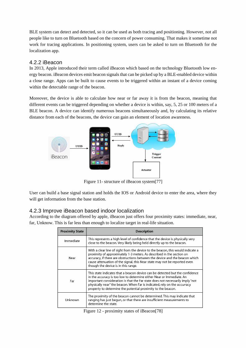
4.2.2 iBeacon In 2013, Apple introduced their term called iBeacon which based on the technology Bluetooth low en-
ergy beacon. iBeacon devices emit beacon signals that can be picked up by a BLE-enabled device within
a close range. Apps can be built to cause events to be triggered within an instant of a device coming
within the detectable range of the beacon.
Moreover, the device is able to calculate how near or far away it is from the beacon, meaning that
different events can be triggered depending on whether a device is within, say, 5, 25 or 100 meters of a
BLE beacon. A device can identify numerous beacons simultaneously and, by calculating its relative
distance from each of the beacons, the device can gain an element of location awareness.
Figure 11- structure of iBeacon system[77]
User can build a base signal station and holds the IOS or Android device to enter the area, where they
will get information from the base station.
4.2.3 Improve iBeacon based indoor localization According to the diagram offered by apple, iBeacon just offers four proximity states: immediate, near,
far, Unknow. This is far less than enough to localize target in real-life situation.
Figure 12 - proximity states of iBeacon[78]

Therefor a lot researches are done to improve the performance.
Faheem [10] applied Server-Side Running Average (SRA) and Server-Side Kalman Filter (SKF) on
iBeacon based indoor localization system. Improved the proximity detection accuracy of iBeacon by
29% and 32% respectively.
Quanyu Wang[72] used cascaded Kalman Filter-Particle Filter (KFPF) algorithm for indoor localiza-
tion. The Kalman Filter (KF) reduced the RSSI fluctuation and then the filtered RSSI values was input
into a Particle Filter (PF) to improve the accuracy of indoor localization. They achieved a 1.03-meters
average 2D localization error and a 1.33-meters average 3D localization error in a replicated real-world
scenario.
4.2.4 other BLE based indoor localization Since iBeacon is a packed technology and the performance is not so satisfying, there can be more pos-
sibilities to focus on BLE based indoor localization.
When Bluetooth is on visible state, BLE advertisements are broadcast on three 2 MHz advertising chan-
nels in quick succession. These channels are nominally labelled 37, 38, and 39 and are widely spaced at
2402 MHz, 2426 MHz and 2480 MHz, respectively[54].
This gives the possibility to use Trilateration, Triangulation and scene analysis (proximity principle is
used on iBeacon) principles to decide the location.
In [79], the author installed Bluetooth scanners inside a shopping mall to track human trace inside in
order to analyze human behavior. His approach based on approximate principle. Log of detection of
devices are saved insider the scanners. And the path can then be reconstructed by combining the logs of
all scanners, where the location of each scanner is added as the location of the device.
Ramsey Faragher and Robert Harle [54] used fingerprinting approach achieved a 2.6 m error 95% for a
density of 1 beacon per 30 𝑚2. Their research made an excellent example of BLE fingerprinting by
taking into consideration of time window, movement speed, fast fading and so on.
Jun-Wei Qiu [9] proposed a self-adaptive approach to decide the parameters of signal propagation
model. He built a dynamic model based indoor localization system. His experiment showed that this can
improve the ranging error in a relationship with the distance of the extra sensors and number of regres-
sion samples. By utilizing the adaptive ranging with device-specific parameters has an improvement of
approximately 19.99% in accuracy
4.3 WIFI based indoor localization Wi-Fi router and access points (APs) are almost everywhere nowadays. The high percentage of coverage
in architectures makes it one of the best candidates for indoor localization. Wi-Fi based indoor localiza-
tion system can be used anywhere there exists Wi-Fi infrastructures. Due to the fact Wi-Fi give mobile
device a non-cost high speed online experience, the most mobile device user would like to keep Wi-Fi
function on and connect to any available APs, this makes it possible to design both tacking and posi-
tioning system.

In January 4, 2016, Wi-Fi Alliance announced a new low power Wi-Fi standard called Wi-Fi HaLow
[80]. The new standard extended Wi-Fi into 900 MHz band which will be considerably with lower speed
but longer range. These new features give Wi-Fi a potential to offer better indoor localization system by
lowering the power consumption, increasing the user acceptance, improving the object penetrate ability
and reducing the AP number and cost while keeping the same coverage inside the architecture.
In order to use Wi-Fi based indoor localization, RSSI or AOA/TOA may need be measured. In Wi-Fi
standards, there are no definition of how RSSI should be achieved. Different hardware supplier may use
different ways and there can be different results when measure a same position under same situation
with different hardware. It is important to be aware of this when design the system. Another obvious
factor to effect RSSI measurement is the material of smartphone, metal case and plastic case may have
different effect. When design a positioning system, being aware of the brand and model of the telephone
can give a better judgement of the case material.
There are currently two open source tools to customize router or Wi-Fi APs, they are OpenWRT[81]
and DD-WRT[82], they can help engineers to customize current available devices to reach the goal.
4.3.1 model based indoor localization As it was discussed in part 3, model-based approaches are popular due to it does not need hard work to
analyze the scene and huge amount of labor to collect the field information. Work done by Jure[8] gives
the newest research based on model-based Wi-Fi indoor localization and there are a lot of introduction
of related work, detailly discussed the advantages and disadvantages. He utilized free space path loss
and ITU models and gave an improvement by adding two additional parameters. At the same time, in
order to have a better dynamic self-adaptive model, RSSI signal from other APs are analyzed to infer
the parameters of the space in the path loss. A third-party router firmware called OpenWRT [81] was
used to modify their APs so that they can turn these Aps into monitor model and manually decided the
channels for the system. In the end, they got a mean error of 2-3 and 3-4 m respectively.
4.3.2 AOA and TDOA based estimation The smartphones are not equipped with enough good and amount of antennas to measure AOA and the
software system can’t assure a fast enough respond to achieve TOA or TDOA approach. The only solu-
tion is to leverage external devices and this is expensive.
Arrat Track and ToneTrack maybe are the best examples of AOA and TOA based smartphone indoor
localization system currently. The author used multi-antennas routers, which are built on top of WARP
software-defined radio platform developed by Mango [85], to measure input signal RSSIs. In the
ToneTrack system, the principle of how to measure AOA through a multi-antenna device and the algo-
rithm was detailly described. With his approach, this system achieved 38 cm accuracy with 6 APs in the
end.
In ToneTrack, multiple signal classification (MUSIC) and matrix-pencil are applied and improved for
this project to reduce the channel-scanning time, which is one of the limit of Wi-Fi based indoor local-
ization approaches. In his field test, the system was able to achieve 0.9-meter median accuracy in a
typical office environment with strong multipaths.
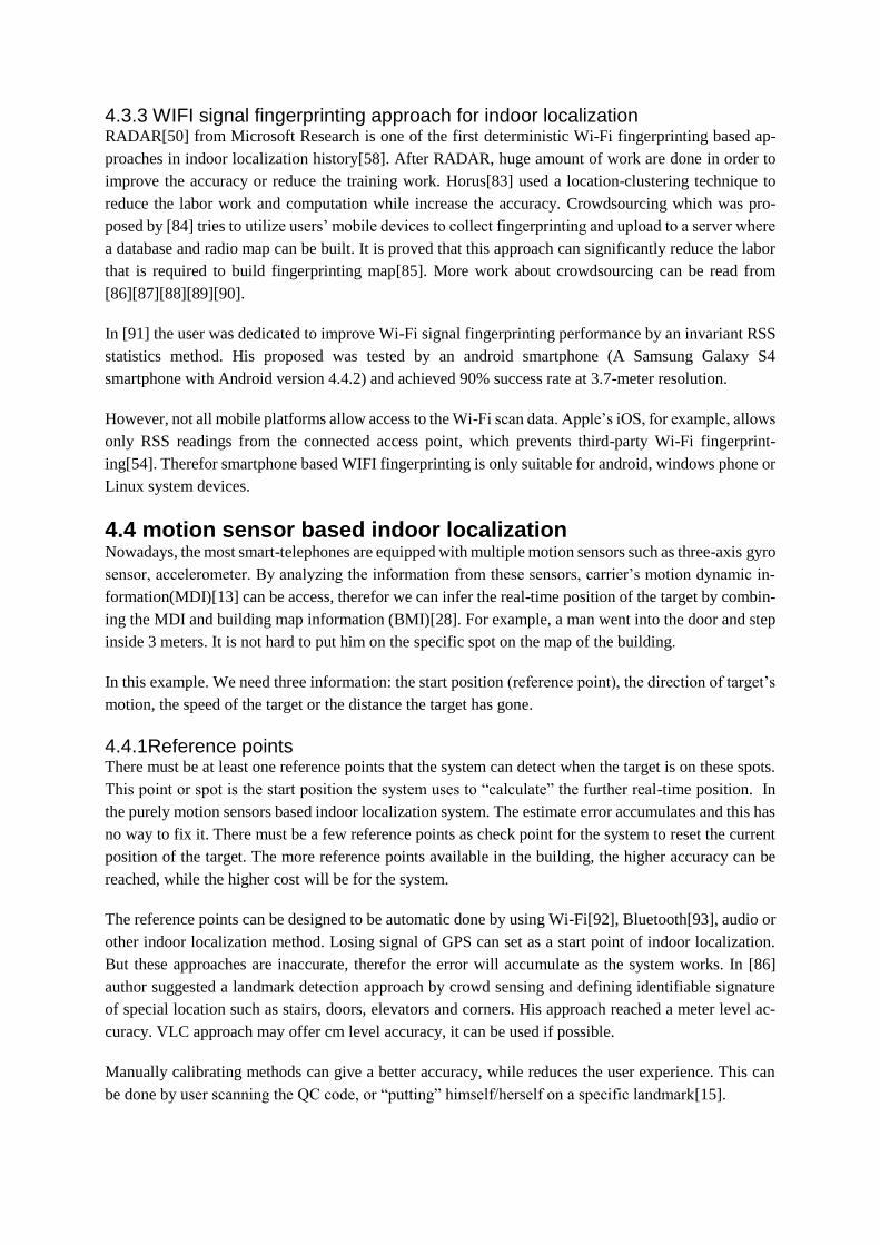
4.3.3 WIFI signal fingerprinting approach for indoor localization RADAR[50] from Microsoft Research is one of the first deterministic Wi-Fi fingerprinting based ap-
proaches in indoor localization history[58]. After RADAR, huge amount of work are done in order to
improve the accuracy or reduce the training work. Horus[83] used a location-clustering technique to
reduce the labor work and computation while increase the accuracy. Crowdsourcing which was pro-
posed by [84] tries to utilize users’ mobile devices to collect fingerprinting and upload to a server where
a database and radio map can be built. It is proved that this approach can significantly reduce the labor
that is required to build fingerprinting map[85]. More work about crowdsourcing can be read from
[86][87][88][89][90].
In [91] the user was dedicated to improve Wi-Fi signal fingerprinting performance by an invariant RSS
statistics method. His proposed was tested by an android smartphone (A Samsung Galaxy S4
smartphone with Android version 4.4.2) and achieved 90% success rate at 3.7-meter resolution.
However, not all mobile platforms allow access to the Wi-Fi scan data. Apple’s iOS, for example, allows
only RSS readings from the connected access point, which prevents third-party Wi-Fi fingerprint-
ing[54]. Therefor smartphone based WIFI fingerprinting is only suitable for android, windows phone or
Linux system devices.
4.4 motion sensor based indoor localization Nowadays, the most smart-telephones are equipped with multiple motion sensors such as three-axis gyro
sensor, accelerometer. By analyzing the information from these sensors, carrier’s motion dynamic in-
formation(MDI)[13] can be access, therefor we can infer the real-time position of the target by combin-
ing the MDI and building map information (BMI)[28]. For example, a man went into the door and step
inside 3 meters. It is not hard to put him on the specific spot on the map of the building.
In this example. We need three information: the start position (reference point), the direction of target’s
motion, the speed of the target or the distance the target has gone.
4.4.1Reference points There must be at least one reference points that the system can detect when the target is on these spots.
This point or spot is the start position the system uses to “calculate” the further real-time position. In
the purely motion sensors based indoor localization system. The estimate error accumulates and this has
no way to fix it. There must be a few reference points as check point for the system to reset the current
position of the target. The more reference points available in the building, the higher accuracy can be
reached, while the higher cost will be for the system.
The reference points can be designed to be automatic done by using Wi-Fi[92], Bluetooth[93], audio or
other indoor localization method. Losing signal of GPS can set as a start point of indoor localization.
But these approaches are inaccurate, therefor the error will accumulate as the system works. In [86]
author suggested a landmark detection approach by crowd sensing and defining identifiable signature
of special location such as stairs, doors, elevators and corners. His approach reached a meter level ac-
curacy. VLC approach may offer cm level accuracy, it can be used if possible.
Manually calibrating methods can give a better accuracy, while reduces the user experience. This can
be done by user scanning the QC code, or “putting” himself/herself on a specific landmark[15].

4.4.2 Heading (Direction) After the system has detected the target on the reference point, the direction of the future motion is
import because it decides where the distances should be added on. And when the target is turning, the
system has to acquire this action.
An absolute direction can be directly measured or estimated by a digital compass, while a relative change
in heading can be measured by gyroscope sensors. However, Due to the interference of external mag-
netic, large-scale iron, steel equipment and so on, the magnetometer output is not stable under indoor
circumstance and there exists large deviation, which will directly affect the position estimation accuracy.
A gyroscope can be used to measure a relative direction change with no impacts from the environment
but the drift error will grow with time. In [94], the authors introduced a fusion algorithm by taking both
magnetometer and gyroscope sensors into consideration. It is
0 1 1 2
D D g m
k k k kh w h w h w h (8)
Where 𝑤𝑖, i=0,1, 2 are weighted factors and 0 1 2 1w w w .
D
kh represent the current direction, g
kh
is the direction change measured from gyroscope and m
kh is the direction change measured form mag-
netometer.
According to his experiment, this algorithm gives a better result than use just gyroscope or magnetom-
eter[94].
4.4.3 steps measurement In order to detect the steps, it is good to observe how people walk first. There are two phases:(1) One of
the feet raises while the other one stays on the ground;(2) The body lean it towards the front and the foot
hits the ground[13]. When the foot hits the ground, vertical acceleration signals with periodic patterns
will be detected by the three-axis accelerometer in a smartphone coordinate system(SCS). This SCS can
be transformed into earth coordinate system by applying a rotation matrix[93], and it will be look like
shown in Figure 13 .
Figure 13 - The acceleration patterns of a pedestrian in stationary and walking states[13]
Another problem of step detecting is that this result contains earth gravity. It is difficult to separate
pedestrian acceleration from that of gravity because the sensor attitude is unknown[13]. But the gravity
in one area is relatively stable, this makes it possible to eliminate it. Chen[93] applied low-pass filter to
remove the gravity and Liu [13] used average of acceleration norm to estimate the magnitude of gravity.

4.4.4 Step Length Calculation There are plenty of ways to determine the step length, one of the most used one is
4max min*L Acc Acc (9)
where δ =𝑑𝑟𝑒𝑎𝑙
𝑑𝑒𝑠𝑡𝑖𝑚𝑎𝑡𝑒𝑑 and should be computed in advance for different users; 𝑑𝑟𝑒𝑎𝑙and 𝑑𝑒𝑠𝑡𝑖𝑚𝑎𝑡𝑒𝑑are real
walking distance and estimated walking distance, respectively. maxAcc is the peak value of acceleration
and minAcc is the bottom value.[95][96][97][98].
Some improved methods are introduced in [99], for example Kim’s algorithm[100] and Tian’s algo-
rithm[101]. Work done by Ho[99] gave us a way to detect step length in a more adaptive and accurate
way. However, utilization of fast Fourier transform(FFT) makes it power consuming. The future system
can use an indirect-positioning topology to work.
4.4.5 position determining After knowing the start point, heading direction, step length and steps, it is not hard to decide the current
position of the target. However, this approach is an open-loop system which means there is no way to
compare the calculated trajectory with the real trace except when target reach the reference points. The
accuracy depends on the calibration design.
Mostly, motion based indoor localization works with other sensors such as Wi-Fi and Bluetooth. Re-
searches show that a fusion system of motion sensor and Wi-Fi can approach a better perfor-
mance[92][13][102].

4.5 Audio (microphone sensor) based indoor localization Comparing with camera or light-based approach, audio approach is more stable to the change of context,
as shown in Figure 14. This gives us more confidence to develop audio (microphone) based indoor
localization system.
Figure 14 -The influence caused by changing contexts of mobile phone[103].
The context represented above is:
(A) in the hand of the user facing the source (B) in the pocket of the user facing the source
(C) in the hand of the user facing away from the
source
(D) in the pocket of the user facing away from the
source
The first acoustic-based localization system was introduced in [104], they place microphones at key
locations and users snap their fingers to give the system audio information, and then the position was
detected.
The microphones on modern smart phone, for example iPhone 6s, is able to sample at 44.1 kHz[105].
According to the Nyquist-Shannon sampling theorem [38], the microphone is able to capture infor-
mation under 22 kHz, and, as a result, it can capture and recognize not only human speech, but also high
frequency sound like music and machine. Therefor, current smart phone can play a good role in sound
sampling and recognizing.
4.5.1 audio based TDOA approach Although sound based signal forms a field like other RF signals, it has a special advantage of utilizing
TOA or TDOA approaches. That is because it travels in a much slower speed than light. This signifi-
cantly reduces the requirement of timer on mobile devices.

According to [106][107], they have successfully localized a group of mobile devices with only ambient
sound and a Wi-Fi network. The method they used is called Ellipsoid, which is a TDOA-based method.
By using at least four receivers with unknown positions, they successfully localized four apple laptops
and four iPhones with a positioning accuracy of approximately 0.28 m.
The Apple products are equipped with High Precision Event Timer (HPET)[108], which makes high
accuracy timer synchronization possible for TOA/TDOA approach. And iPhone have an good inbuilt
audio pipeline and this makes it have very little input latencies. Work done in [107] were able to syn-
chronize the devices within an accuracy of 0.1 ms through the Network Time Protocol (NTP). However,
in Android system smartphones, this accuracy in time synchronization, even utilizing the NTP, is cur-
rently not possible, and the measurements are very noisy[109].
In [109], the authors developed their localization system in the native layers of Android using the Native
Development Kit(NDK) in order to reduce the overhead latency of audio data collecting. In [110], the
authors introduced a hybrid system called NEST which used image and audio approach on Android
device. In the acoustics-based part, the devices are used as anchors at known locations to estimate the
sound source location. The TDOA was estimated by identifying the peak location where the maximum
of the cross-correlation between the two signals occurs. The recorded sound events and corresponding
time stamps were processed on a common smartphone which acted as a master in the system and the
Fast Fourier Transformation (FFT) filter was deployed to reduce the computation. Synchronization off-
set and start time error between devices are estimated and subtracted from time delay to calibrated
TDOA for the positioning of the source. Their acoustics-based system achieved a ±15 cm in the x-
direction and ±80 cm in the y-direction. The accuracy in the x-direction is better because the sensor
array baseline is relatively short compared to its range to the source.
4.5.2 audio based fingerprinting approach As it was said before, the audio information can be also regard as some kind of field, where there is
field, there can be a field map of signals. However, different from other signals, sound information is
complicated. Firstly, the sound signature of a place is almost unarrangeable. For example, some place
such as home, museum or theater may be quiet most of the time, which means there can be totally no
sound information to utilize. In the public place such as shopping mall and airport, there can be too
much noise which is require heavy computation to process, which is challenge to smartphone due to is
limited process ability and battery restrain. Special infrastructures which generate regular sound infor-
mation can be annoying even health harness for human beings.
Secondly, privacy can be a problem since the sound may contains some sensitive private information,
thus a sound based indoor localization system must solve this problem before it can be accepted by the
users.
But there are still possibilities. A DECENT acoustic fingerprinting technique called Acoustic Back-
ground Spectrum(ABS) was introduced in [111]. It firstly calculated an acoustic spectrum and then
filtered the transient sound so that it can be time-invariant.
In [103],the author tested the relationship between sample time and accuracy and power consuming.
They found out that 15s can offer a good accuracy with a reasonable energy consumption. In order to
achieve high accuracy, target’s schedules were acquired and fingerprinting data were collected and
stored in a backend server. The most computation work are done in the server instead of telephone so

that it can offer a better computation capacity and low power consuming on the telephone part. The
system approximates the place where the user is by detecting the specific background sound in the en-
vironment or analyzing the speakers’ identity by the content of speech. The background noise was fil-
tered by typical Voice Activity Detection(VAD).
In [46], author introduced sound sense which collects sound data by the microphone and uses time-
domain and frequency-domain feature of the sound. Instead of getting an accuracy localization result,
they used approximate principle to decide a room level result.
4.6 Magnetic field based approach We are living under a nature magnetic field, which is also possible to be used for localization[112][113].
The magnetic field covers the whole earth, that offer it a chance to be used everywhere without any
limit. Campus was invented by Chinese thousands year ago and they are offering navigation service in
wild area. Not like wild area where there is no interference for magnetic-filed from metals and electric
devices, indoor environment is complicated, there is no pattern for the field distribution in indoor sce-
nario. However, this uniqueness gives the chance for fingerprinting approach to show its value. The
more special the indoor magnetic-field-distribution is, the easier for fingerprinting approach to build a
special database or field map and this map is tested to be stable by[112]. An indoor localization system
based on RSS-Magnetic fingerprinting was introduced in [113].
Mostly, magnetic field approach does not work alone because it has a possibility to mismatch(target can
be located in a wrong building[112]) . A lot fusion system can take magnetic field into account such as
work done in [114],[115]. The more detail about fusion system will be discussed in next section.
4.7 Multi-approach indoor localization In the previous sections, indoor localization based on every sensor in the smart phones are introduced.
They all have their advantages and disadvantage. That is why there is still not a standard for all the
applications. But how about we utilize not only one sensor for the localization work? Then it comes to
a topic about multi sensor approach, which use a combination of more than one sensors as complement
to each other to give a more robust and accurate result.
Actually, multiple sensors and signals of opportunity have been used for indoor positioning and navi-
gation applications since long time ago and the researches on this topic has been taken for many years
[116][114]. Examples of such sensors include accelerometers, gyroscopes, compasses, cameras, prox-
imity sensors, and electromyography sensors as they were introduced in the previous parts. The studies
presented in [117][118][119] show that positioning accuracy can be improved by the incorporation of
current RSSI measurements in conjunction with knowledge of motion dynamics and historical meas-
urements.
There are mostly three ways of utilizing multi-sensors:
(1) SLAM: As it was said that fingerprinting approach has a main disadvantage that it requires too
much labor to build the signal map before it can be used. So one of the solutions is using other
available sensors to localize itself before the signal map was built and in the meanwhile collecting
the RSSI information and upload to the server where signal map is built. This is called Simultaneous
Localization and Mapping (SLAM)[120].
(2) Fusion: All the sensor that can be used can make their contribution to the final result. That is to
take all the localization information into account and evaluate the most likely position of the target.
For example [13][113][92][94].
(3) Multi-availability: when one sensor doesn’t work, then use another. For example, sometimes Blue-
tooth can’t be used due to that the user turned it off, and Wi-Fi is available, then can use Wi-Fi as
the main approach. Or there can be sometimes neither Wi-Fi and Bluetooth works, then utilizing
other sensors become the only solution[121].
4.6.1 SLAM with multi-sensors Fingerprinting can offer a relative accurate indoor localization result with low computation and high
respond speed. However, the creating process of the signal map is time consuming and requires huge
amount of labor work. The idea behand SLAM is to use other available resource to obtain the signal
map. When it comes to smartphone perspective, the available sensors are mainly VLC based (4.1), mo-
tions sensors (4.4) and magnetometer.
Faragher[51] proposed a hybrid system which used a hip-mounted IMU to obtain the location of user
while the user uses smartphone to measure the RSSI. He used a distributed particle filet to filter the drift
error of IMU approach and suggest the user to revisit the locations to help the system to observe and
correct the drifts.
Mirowski [15] built a system on Android phone which can gather fingerprinting of Wi-Fi RSS, Blue-
tooth RSS, 4G LTE RSRP and magnetic field magnitude by the information from IMU and pedestrian
dead reckoning(PDR) approach. The user just need to keep the smartphone inside the pocket, while a
lot of article require the user to hole it in hand in order to have a better accuracy. They used a modified
Graph-SLAM[122][123] to synthesize the measurements from different sensors and infer the trajectory.
4.6.2 Fusion solutions Scholars have noticed that magnetic matching (MM) results have small fluctuations[113], but it have a
risk of mismatching due to low magnetic fingerprint dimension[112], in contrast, Wi-Fi results have a
low mismatch rate but suffer from larger fluctuations [124] (The term “mismatch rate” means “the per-
centage of position results that have a position error of over 15 m”)[114]. Therefore, there is a potential
to use Wi-Fi for a rough positioning, and then use MM for a more precise localization. Article [114]
proposed a fusion system which combined PDR,Wi-Fi fingerprinting and magnetic matching (MM)
approaches to use off-the-shelf sensors in consumer portable devices and existing Wi-Fi infrastructures.
WAIPO[14] is an indoor localization system with the fusion of Wi-Fi and other in-built sensors such as
camera, Bluetooth, accelerometer, magnetometer for surrounding sensing, which is easy for promotion
and application [26]. The system utilized a User Location Preference (ULP) model with fingerprinting
data from other sensors to gather users’ location preference. When localization service is need, it esti-
mates the location by sensing the co-occurrence and non-concurrence people around.
HIPE[13] is a hybrid approach fusing a smartphone’s motion sensors with Wi-Fi fingerprints. The
smartphone’s motion sensors measure the user’s motion dynamics information, such as step count (by
an accelerometer) and heading direction (by a digital compass). To perform the fusion of motion infor-
mation for position estimates, a hidden Markov model is used along with a grid-based filter algorithm
and the Viterbi algorithm.
For the integration of different localization results, the literature [125] uses a Kalman filter to fuse the
information from different sensors[66], while the research [15] utilizes a bundle adjustment approach to
implement simultaneous localization and mapping.
5 Design of indoor localization All the technologies are developed to solve some problems or make contribution to the world. This need
to done not only by developing the science, but also by applying the knowledge in real environment.
That why this article is always talking about those really realistic approaches by focusing on smart
telephones.
In the previous parts this article has concluded the knowledge structure of indoor localization with cita-
tions. The aim of the previous part is to help the reader to have a comprehensive understanding of indoor
localization in a wide range.
This part tries to use the above knowledge to solve real engineering problem, explain how to design a
indoor localization system. In this section, some question about (1) the processing of designing the sys-
tem; (2) approaches to improve the system (3) standard to evaluate the system will be answered.
An example of designing one indoor localization system in UiT Narvik campus will be introduced to
illustrate stated principles and procedures.
5.1 the processing of designing the system When it comes to the procedure of designing an indoor localization system, there can divided into the
following 9 steps:
1) Need analyzing: In this part, the needs of the application should to be listed. Different applica-
tions may have different requirement on accuracy and approach availability. For example,
teacher locating at school may require room level accuracy while customer shopping intention
monitoring may require cm level. Audio based localization maybe an awful idea in museum
but can be good a busy shopping mall to detect which shop a target is.
2) Field inspecting: this helps to find the resources available in the current system building. Wi-Fi
APs, iBeacon devices light system, acoustic sound distributions can be listed as candidate re-
sources.
3) System structure and topology decision: Firstly, it is a tracking system or positioning system
need to be decided. Secondly, which topology should be used for this system. Thirdly, the de-
signer can search for possibilities to improve the system by modify the layout of external de-
vices.
4) Device/devices and sensors choosing: Sensor-availability is limited by the device. And mostly,
practically, smartphone is the best choice. In some occasions like huge supermarket or airport,
targets may use extra device like charts, additional sensors are possible. When the device is
decided, the program platform is also decided (ios, Android or Windowsphone for mobile de-
vice system or windows and MacOs for laptop). Which sensor to choose sometime is depend
on the infrastructure such as Wi-Fi and Bluetooth. And it is also limited by the topology of the
system. In a tracking system, camera and IMU may not be available.
5) Principle decision: There are five principle options as introduced in 3.3. The designer decides
the principle according to the need and sensors.
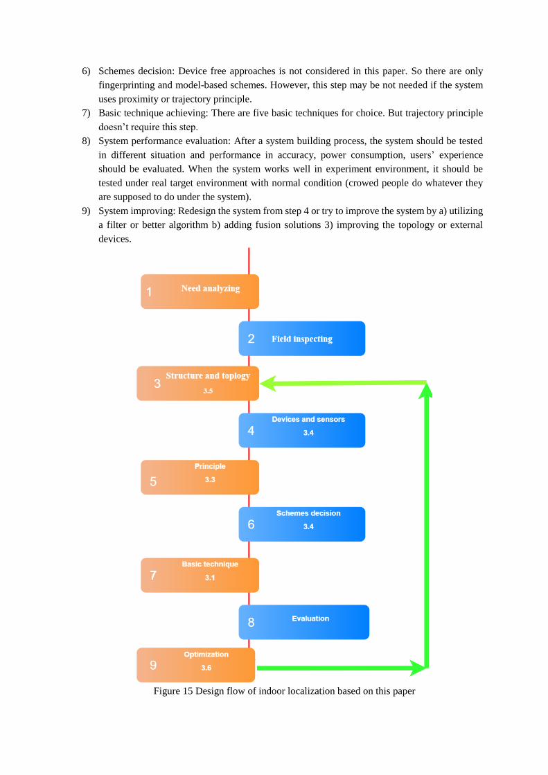
6) Schemes decision: Device free approaches is not considered in this paper. So there are only
fingerprinting and model-based schemes. However, this step may be not needed if the system
uses proximity or trajectory principle.
7) Basic technique achieving: There are five basic techniques for choice. But trajectory principle
doesn’t require this step.
8) System performance evaluation: After a system building process, the system should be tested
in different situation and performance in accuracy, power consumption, users’ experience
should be evaluated. When the system works well in experiment environment, it should be
tested under real target environment with normal condition (crowed people do whatever they
are supposed to do under the system).
9) System improving: Redesign the system from step 4 or try to improve the system by a) utilizing
a filter or better algorithm b) adding fusion solutions 3) improving the topology or external
devices.
Figure 15 Design flow of indoor localization based on this paper
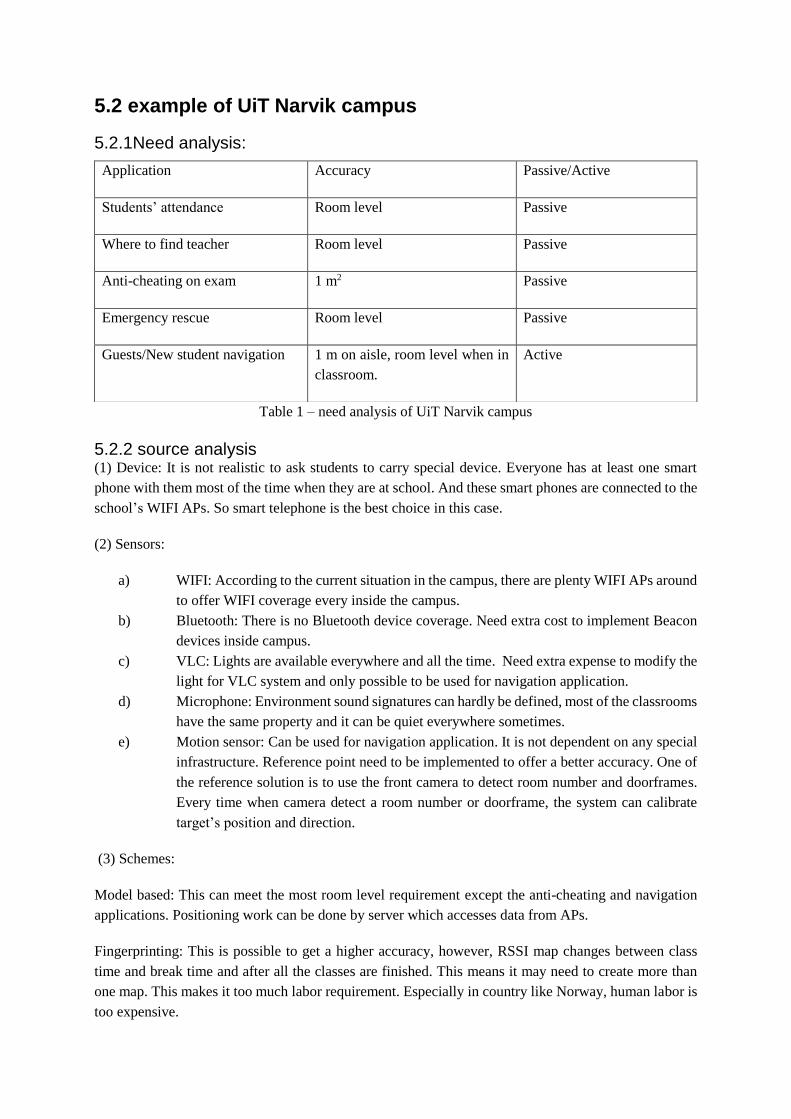
5.2 example of UiT Narvik campus
5.2.1Need analysis:
Table 1 – need analysis of UiT Narvik campus
5.2.2 source analysis (1) Device: It is not realistic to ask students to carry special device. Everyone has at least one smart
phone with them most of the time when they are at school. And these smart phones are connected to the
school’s WIFI APs. So smart telephone is the best choice in this case.
(2) Sensors:
a) WIFI: According to the current situation in the campus, there are plenty WIFI APs around
to offer WIFI coverage every inside the campus.
b) Bluetooth: There is no Bluetooth device coverage. Need extra cost to implement Beacon
devices inside campus.
c) VLC: Lights are available everywhere and all the time. Need extra expense to modify the
light for VLC system and only possible to be used for navigation application.
d) Microphone: Environment sound signatures can hardly be defined, most of the classrooms
have the same property and it can be quiet everywhere sometimes.
e) Motion sensor: Can be used for navigation application. It is not dependent on any special
infrastructure. Reference point need to be implemented to offer a better accuracy. One of
the reference solution is to use the front camera to detect room number and doorframes.
Every time when camera detect a room number or doorframe, the system can calibrate
target’s position and direction.
(3) Schemes:
Model based: This can meet the most room level requirement except the anti-cheating and navigation
applications. Positioning work can be done by server which accesses data from APs.
Fingerprinting: This is possible to get a higher accuracy, however, RSSI map changes between class
time and break time and after all the classes are finished. This means it may need to create more than
one map. This makes it too much labor requirement. Especially in country like Norway, human labor is
too expensive.
Application Accuracy Passive/Active
Students’ attendance Room level Passive
Where to find teacher Room level Passive
Anti-cheating on exam 1 m2 Passive
Emergency rescue Room level Passive
Guests/New student navigation 1 m on aisle, room level when in
classroom.
Active
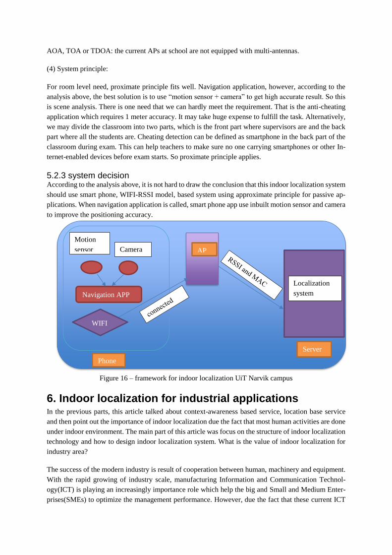
AOA, TOA or TDOA: the current APs at school are not equipped with multi-antennas.
(4) System principle:
For room level need, proximate principle fits well. Navigation application, however, according to the
analysis above, the best solution is to use “motion sensor + camera” to get high accurate result. So this
is scene analysis. There is one need that we can hardly meet the requirement. That is the anti-cheating
application which requires 1 meter accuracy. It may take huge expense to fulfill the task. Alternatively,
we may divide the classroom into two parts, which is the front part where supervisors are and the back
part where all the students are. Cheating detection can be defined as smartphone in the back part of the
classroom during exam. This can help teachers to make sure no one carrying smartphones or other In-
ternet-enabled devices before exam starts. So proximate principle applies.
5.2.3 system decision According to the analysis above, it is not hard to draw the conclusion that this indoor localization system
should use smart phone, WIFI-RSSI model, based system using approximate principle for passive ap-
plications. When navigation application is called, smart phone app use inbuilt motion sensor and camera
to improve the positioning accuracy.
Figure 16 – framework for indoor localization UiT Narvik campus
6. Indoor localization for industrial applications In the previous parts, this article talked about context-awareness based service, location base service
and then point out the importance of indoor localization due the fact that most human activities are done
under indoor environment. The main part of this article was focus on the structure of indoor localization
technology and how to design indoor localization system. What is the value of indoor localization for
industry area?
The success of the modern industry is result of cooperation between human, machinery and equipment.
With the rapid growing of industry scale, manufacturing Information and Communication Technol-
ogy(ICT) is playing an increasingly importance role which help the big and Small and Medium Enter-
prises(SMEs) to optimize the management performance. However, due the fact that these current ICT
Server
Localization
system
Phone
Camera
Motion
sensor
Navigation APP
WIFI
AP

solutions lack the ability to provide the accurate information to the right person, the ICT is already a
challenge for mangers now[126]. It is urgent to implement these ICT platforms with context-awareness
ability[127].
6.1 Work activity management When the manage can know the location of workers in real-time or the system can record the trajectory
of workers related to the time information. The manager can give instructions too right person according
their current location. Trajectory recording system can assure that workers or patrolman does their job
properly. This is extremely important when it relate to daily factory infrastructure inspection or security
patrolling.
Peng Lin[128] used his system to monitor the real-time behavior for large-dam construction site in order
to have better documentation, analysis and understanding of the worker performance and improve the
poor practices. To achieve this goal, the system predefined the trajectory worker are supposed to follow,
then the real-time position of workers is monitored and recorded so that it can draw a real trajectory. By
comparing these two trajectories by Euclidean distance, dynamic time warping (DTW), or longest com-
mon subsequence (LCSS), the behavior analysis can be done. The collected data can be sent to industrial
engineers to improve the performance and can be used by HR (human resource) as a reference to eval-
uate the work behavior of every individual worker.
6.2 Risk management and emergency rescue Security is a vital issue for all the industrial activities. Indoor localization can help to manage the risk
and rescue when disaster happened.
In an indoor localization system, risk sensitive area can be marked, when the system detect anyone
except maintenance related employee get close to theses areas, the system can alarm the approaching
person and the manager when it is necessary. When a worker detected new risk situation, the worker
can help to update the system. So the system can alarm other colleagues.
When a accident happed, it can be hard for rescue crew to find injured person. They don’t know how
many people are trapped and where they are. Indoor localization system can give this information when
the system is still working, or give the last position of workers when related infrastructure are broken.
This information can help the emergency team to save people in a much efficient and confident way.
Peng Lin in his later work in [7] developed an indoor localization system with artificial neural net-
work(ANN) risk assessment function in order to improve the safety management for tunnels workers.
In this system, real-time position of workers with smartphones is monitored. They can report and share
real-time risk information and be alarmed when they were approaching a risk area. The company can
build and maintenance risk issues management system based on the reported information.
6.3 Factory maintenance The scales of factories are growing in a rapid speed the layout of the site is updating frequently. With
the help of wireless network sensors and system, devices position is much more flexible than ever. On
one hand, this gives huge benefits for industry development, however on the other hand, this gives
maintenance work extraordinary challenges. Nowadays, factories are equipped with advanced machines
which need professional maintenance from external service provider or machine supplier[129]. It is
important to reduce the time for engineers to navigate himself to the device.

Dipl in his work[130], detailly explained that the spatial context information can significantly optimize
the maintenance process in the modern SmartFactory. The indoor navigation service help the engineer
to find the target device in a rapid and efficient way and enhanced the quality of services and process.
This can lead to a better device reachability and overall equipment effectiveness.

7. Further work
7.1 Build a system This article is mainly to systematically introduce every side of indoor localization. This is for those who
are interested in indoor localization technology but suffer from drowning in the articles that focuses on
special side or sides about this topic. Almost every section of this article can be chosen as a future
research area, however the combination of different sections can be hundreds of possibilities. That is
what we can see in the current thousands of research works.
However, due to the limit of time. A system could not be built to apply the knowledge this article studied
before. Building a system not only requires the design principles and indoor localization knowledges, it
requires hardware system building and software design, testing and debugging. For example Jure Tuta
et al[8] published their work after two-year-long team research, Xiong [61] finished his doctor degree
research by achieving AOA based indoor localization with the special hardware with multiple antennas.
I have already contacted with some companies, which have research and application of indoor localiza-
tion, in china. Hopefully I could build real life indoor localization system with them.
7.2 Analysis and improve the system The research work can be done by three steps: 1) study current achievement; 2) build a system; 3) im-
prove the system. This article is only the first step. And 7.1 will be the second. As we have talked about
system evaluation and improvement algorithms. I want to apply them in the real-life environment in-
stead of experimental setups. In the future project, I will decide the device and approaches after analyz-
ing the real-life situation and apply algorithms and topologies to reach the requirements of needs.
7.3 Implement the system design part In this article, I wanted to introduce the design principle for indoor localization, which is so far from my
knowledge no one ever did this work before. There is only one article I found in our data base from
Jorge Juan Robles in his “Considerations in the Design of Indoor Localization Systems for Wireless
Sensor Networks”[131], but this article just gave some little aspect of indoor localization system design
for example, energy consumption and protocol introduction. It does not contain principles, devices and
other approaches.
But my experience and knowledge is limited, this topic is still just a start of all. Hope more researcher
would like to give their implements to give more comprehensive, abstract and complete design proce-
dures in the future work.
In operation research, one of the important subject in industrial engineering, talked about decision anal-
ysis. In the future work, I would like to implement this into system design part also. Hope there can be
better designs.

8. Conclusion This is an article talking about wireless indoor localization and applications. Here wireless does not only
mean WIFI, Bluetooth, ZigBee, wireless HART and other RF signals, it also contains sound waves,
light signals. It tried to give a systematical, structural description of indoor localization. It is a survey
and it is also not only a survey, as far as the author knows, there is not a single article which contains so
many aspects of indoor localization. Talking about indoor localization technology, there is not a single
article which talk about it so completely. Of course, indoor localization is not a complete system yet.
Only limited start-up companies trying to concur this market. This subject is only a little branch of
electrical engineering or mathematic subject. There is not text book available yet talking about this area.
That is a limit for more passionate students coming to contribute their intelligence and hard work. This
article can be a beginning of this kind of book.
This article systematically described the basic techniques of indoor localization. Chapter 3 give the basic
technological knowledge of indoor localization. This part is concluded from over hundreds articles from
the database. After reading this part, the reader can have a better understanding of future articles. They
can know which area of indoor localization the future article is doing. They can also know what they
can use they want to build their own indoor localization system or make their own contribution in indoor
localization work.
Chapter 4 is smart phone based indoor localization. This part is based on the opinion that smartphone is
the common device everyone takes with all the time. Therefore, smartphone is the most potential plat-
form and most possible way to build indoor localization system. All the sensors available inside the
modern smartphone are listed and how every sensor can be used for indoor localization applications are
introduced separately in the beginning. In the end, fusion solutions are talked.
Chapter 5 talked about designing of indoor localization. This topic never been talked before, thanks to
the work in chapter 3 and chapter 4, this topic can be started based on the systematical knowledge. In
the end, some famous algorithms are added. Due to my limit knowledge, there can be some missing
algorithms. I would like to add them in my future work.
Chapter 6 talked about industrial applications of indoor localization. Some current applications are in-
troduced.

9. References [1] A. K. Day, “Understanding and Using Context,” pp. 4–7, 2001.
[2] B. Jiang and X. Yao, “Location-based services and GIS in perspective,” Comput. Environ. Urban
Syst., vol. 30, no. 6, pp. 712–725, 2006.
[3] NASA, “Global Positioning System History,” 2015. [Online]. Available:
https://www.nasa.gov/directorates/heo/scan/communications/policy/GPS_History.html.
[4] S. Ryschka, M. Murawski, and M. Bick, “Location-Based Services,” Bus. Inf. Syst. Eng., vol.
58, no. 3, pp. 233–237, 2016.
[5] K. Ozsoy, A. Bozkurt, and I. Tekin, “2D Indoor positioning system using GPS signals,” 2010
Int. Conf. Indoor Position. Indoor Navig., no. September, pp. 15–17, 2010.
[6] N. E. KLEPEIS et al., “The National Human Activity Pattern Survey (NHAPS): a resource for
assessing exposure to environmental pollutants,” J. Expo. Anal. Environ. Epidemiol., vol. 11, no.
3, pp. 231–252, 2001.
[7] P. Lin, Q. Li, Q. Fan, X. Gao, and S. Hu, “A real-time location-based services system using WiFi
fingerprinting algorithm for safety risk assessment of workers in tunnels,” Math. Probl. Eng.,
vol. 2014, 2014.
[8] J. Tuta and M. Juric, “A Self-Adaptive Model-Based Wi-Fi Indoor Localization Method,”
Sensors, vol. 16, no. 12, p. 2074, 2016.
[9] J. W. Qiu, C. P. Lin, and Y. C. Tseng, “BLE-based collaborative indoor localization with
adaptive multi-lateration and mobile encountering,” IEEE Wirel. Commun. Netw. Conf. WCNC,
vol. 2016–Septe, no. Wcnc, 2016.
[10] F. Zafari, I. Papapanagiotou, M. Devetsikiotis, and T. J. Hacker, “Enhancing the Accuracy of
iBeacons for Indoor Proximity-based Services.”
[11] N. S. Correal, S. Kyperountas, Q. Shi, and M. Welbom, “An UWB Relative Location System,”
pp. 394–397.
[12] J. Chai et al., “Reference tag supported RFID tracking using robust support vector regression
and Kalman filter,” Adv. Eng. Informatics, vol. 32, pp. 1–10, 2017.
[13] J. Liu, R. Chen, L. Pei, R. Guinness, and H. Kuusniemi, “A hybrid smartphone indoor positioning
solution for mobile LBS,” Sensors (Switzerland), vol. 12, no. 12, pp. 17208–17233, 2012.
[14] F. Gu, J. Niu, and L. Duan, “WAIPO: A Fusion-Based Collaborative Indoor Localization System
on Smartphones,” IEEE/ACM Trans. Netw., pp. 1–14, 2017.
[15] P. Mirowski, T. K. Ho, S. Yi, and M. Macdonald, “SignalSLAM Simultaneous Localization and
Mapping with Mixed WiFi , Bluetooth , LTE and Magnetic Signals Bell Labs SignalSLAM :
Outline • Goal : RF signal fingerprinting • Scenario : crowd-source RF mapping from the pocket
• Methods • Pedestrian dead recko,” no. October, pp. 28–31, 2013.
[16] J. Miranda et al., “From the Internet of Things to the Internet of People,” IEEE Internet Comput.,
vol. 19, no. 2, pp. 40–47, 2015.
[17] B. N. Schilit and M. M.Theimer, “disseminating active map information to mobile hosts,” 1994.

[18] ESRI, “What is location allocation?,” vol. 9, no. 2011/01/05, 2010.
[19] S. Dhar and U. Varshney, “Challenges and business models for mobile location-based services
and advertising,” Commun. ACM, vol. 54, no. 5, p. 121, 2011.
[20] B. Liu, W. Zhou, T. Zhu, L. Gao, T. Luan, and H. Zhou, “Silence is Golden: Enhancing Privacy
of Location-Based Services by Content Broadcasting and Active Caching in Wireless Vehicular
Networks,” IEEE Trans. Veh. Technol., vol. PP, no. 99, pp. 1–1, 2016.
[21] Berg Insight, “Mobile location based services,” Encycl. Multimed. …, 2014.
[22] W. L. Services, “Introduction 1.1,” vol. 9, 2005.
[23] P. a. Zandbergen and S. J. Barbeau, “Positional Accuracy of Assisted GPS Data from High-
Sensitivity GPS-enabled Mobile Phones,” J. Navig., vol. 64, no. 3, pp. 381–399, 2011.
[24] statista, “https://www.statista.com.” [Online]. Available: https://www.statista.com.
[25] R. Mautz, “Overview of current indoor positioning systems,” Geod. Cartogr., vol. 35, no. 1, pp.
18–22, 2009.
[26] M. Azizyan, R. R. Choudhury, and I. Constandache, “SurroundSense : Mobile Phone
Localization via Ambience Fingerprinting,” MobiCom ’09, pp. 261–272, 2009.
[27] R. F. Brena et al., “Evolution of Indoor Positioning Technologies : A Survey,” vol. 2017, 2017.
[28] J. Park, J. Chen, and Y. K. CHo, “Self-corrective knowledge-based hybrid tracking system using
BIM and multimodal sensors,” Adv. Eng. Informatics2, vol. 32, pp. 126–138, 2017.
[29] M. Moussa and M. Youssef, “Smart devices for smart environments: Device-free passive
detection in real environments,” 7th Annu. IEEE Int. Conf. Pervasive Comput. Commun. PerCom
2009, no. Mv, 2009.
[30] B. G. Yu, G. Lee, H. G. Han, W. S. Ra, and T. W. Kim, “A Time-Based Angle-of-Arrival Sensor
Using CMOS IR-UWB Transceivers,” IEEE Sens. J., vol. 16, no. 14, pp. 5563–5571, 2016.
[31] X. Li, K. Pahlavan, M. Latva-aho, and M. Ylianttila, “Comparison of indoor geolocation
methods in DSSS and OFDM wireless LAN systems,” Veh. Technol. Conf. 2000. IEEE VTS-
Fall VTC 2000. 52nd, vol. 6, pp. 3015–3020 vol.6, 2000.
[32] T.-H. Do and M. Yoo, “An in-Depth Survey of Visible Light Communication Based Positioning
Systems,” Sensors, vol. 16, no. 5, p. 678, 2016.
[33] C. Drane, M. Macnaughtan, and C. Scott, “Positioning GSM telephones,” IEEE Commun. Mag.,
vol. 36, no. 4, pp. 46–59, 1998.
[34] H. Liu, “Survey of Wireless Indoor Positioning Techniques and Systems,” vol. 37, no. 6, pp.
1067–1080, 2007.
[35] H. Liu, H. Darabi, P. Banerjee, and J. Liu, “Survey of wireless indoor positioning techniques and
systems,” IEEE Trans. Syst. Man Cybern. Part C Appl. Rev., vol. 37, no. 6, pp. 1067–1080, 2007.
[36] S. Y. Seidel and T. S. Rapport, “914 MHz Path Loss Prediction Model for Indoor Wireless
Communication in Multifloored Buildings,” IEEE Transactions on Antennas and Propagation,
vol. 40(2). pp. 207–217, 1992.

[37] Y. Du, D. Yang, and C. Xiu, “A novel method for constructing a WIFI positioning system with
efficient manpower,” Sensors (Switzerland), vol. 15, no. 4, pp. 8358–8381, 2015.
[38] L. Kanaris, A. Kokkinis, G. Fortino, A. Liotta, and S. Stavrou, “Sample Size Determination
Algorithm for fingerprint-based indoor localization systems,” Comput. Networks, vol. 101, pp.
169–177, 2016.
[39] S. Yiu, M. Dashti, H. Claussen, and F. Perez-Cruz, “Wireless RSSI fingerprinting localization,”
Signal Processing, vol. 131, pp. 235–244, 2017.
[40] B. Ferris, D. Fox, and N. Lawrence, “WiFi-SLAM using Gaussian process latent variable
models,” Proc. 20th Int. Jt. Conf. Artifical Intell., pp. 2480–2485, 2007.
[41] G. Mao, B. Fidan, and B. Anderson, “Wireless sensor network localization techniques,” Comput.
Networks, vol. 51, no. 10, pp. 2529–2553, 2007.
[42] D. Zhang, F. Xia, Z. Yang, and L. Yao, “Localization Technologies for Indoor Human
Tracking,” no. 60903153, 2010.
[43] K. Al Nuaimi and H. Kamel, “A survey of indoor positioning systems and algorithms,” 2011 Int.
Conf. Innov. Inf. Technol. IIT 2011, pp. 185–190, 2011.
[44] C. di Flora, M. Ficco, S. Russo, and V. Vecchio, “Indoor and Outdoor Location Based Services
for Portable Wireless Devices,” 25th IEEE Int. Conf. Distrib. Comput. Syst. Work., pp. 244–250,
2005.
[45] N. Newman, “Apple iBeacon technology briefing,” J. Direct, Data Digit. Mark. Pract., vol. 15,
no. 3, pp. 222–225, 2014.
[46] H. Lu, W. Pan, N. Lane, T. Choudhury, and A. Campbell, “SoundSense: scalable sound sensing
for people-centric applications on mobile phones,” Proc. 7th Int. Conf. Mob. Syst. Appl. Serv.,
pp. 165–178, 2009.
[47] R. Want, A. Hopper, V. Falcão, and J. Gibbons, “The active badge location system,” ACM Trans.
Inf. Syst., vol. 10, no. 1, pp. 91–102, 1992.
[48] N. B. Priyantha, A. Chakraborty, and H. Balakrishnan, “The Cricket Location-Support System,”
vol. 2000, no. August, 2000.
[49] L. M. Ni, Y. Liu, Y. C. Lau, and A. P. Patil, “LANDMARC: Indoor Location Sensing Using
Active RFID,” Wirel. Networks, vol. 10, no. 6, pp. 701–710, 2004.
[50] P. B. and V. N. Padmanabhan, “RADAR: An in-building RF based user location and tracking
system,” Proc. IEEE INFOCOM 2000. Conf. Comput. Commun. Ninet. Annu. Jt. Conf. IEEE
Comput. Commun. Soc. (Cat. No.00CH37064), vol. 2, no. c, pp. 775–784, 2000.
[51] R. M. Faragher, C. Sarno, and M. Newman, “Opportunistic radio SLAM for indoor navigation
using smartphone sensors,” Rec. - IEEE PLANS, Position Locat. Navig. Symp., pp. 120–128,
2012.
[52] S.-W. Yang, S. X. Yang, and L. Yang, “Method of improving WiFi SLAM based on spatial and
temporal coherence,” 2014 IEEE Int. Conf. Robot. Autom., pp. 1991–1996, 2014.
[53] O. Sutton, “Introduction to k Nearest Neighbour Classification and Condensed Nearest
Neighbour Data Reduction,” Introd. to k Nearest Neighb. Classif., pp. 1–10, 2012.
[54] R. Faragher and R. Harle, “Location Fingerprinting With Bluetooth Low Energy Beacons,” vol.
33, no. 11, pp. 2418–2428, 2015.
[55] J. Kocijan, Modelling and control of dynamic systems using gaussian process models. 2016.
[56] Y. Chen, J. Yang, W. Trappe, and R. P. Martin, “Detecting and localizing identity-based attacks
in wireless and sensor networks,” IEEE Trans. Veh. Technol., vol. 59, no. 5, pp. 2418–2434,
2010.
[57] Recommendation ITU-R P.1238-1 et al., “Propagation Data And Prediction Methods for the
Planning of Indoor Radiocommunication systems and Radio Local Area networks in the
Frequency Range 900 MHz to 100 GHz,” Dermatol. Surg., vol. 39, no. 3 Pt 2, pp. I–III, 1999.
[58] H. Aly and M. Youssef, “An Analysis of Device-Free and Device-Based WiFi-Localization
Systems,” 2015.
[59] A. Eleryan, M. Elsabagh, and M. Youssef, “Synthetic generation of radio maps for device-free
passive localization,” GLOBECOM - IEEE Glob. Telecommun. Conf., pp. 0–4, 2011.
[60] M. Ghaddar, L. Talbi, T. A. Denidni, and A. Charbonneau, “Modeling human body effects for
indoor radio channel using UTD,” Electr. Comput. Eng. 2004. Can. Conf., vol. 3, no. l, p. 1357–
1360 Vol.3, 2004.
[61] J. I. E. Xiong, “Pushing the Limits of Indoor Localization in Today ’ s Wi-Fi Networks,” 2015.
[62] E. C. L. Chan, G. Baciu, and S. C. Mak, “Properties of channel interference for Wi-Fi location
fingerprinting,” J. Commun. Softw. Syst., vol. 6, no. 2, pp. 56–64, 2010.
[63] A. Goldsmith, “Wireless Communications,” Wirel. Commun., p. 250, 2005.
[64] B. Ferris, D. Hahnel, and D. Fox, “Gaussian Processes for Signal Strength-Based Location
Estimation,” Proc. Robot. Sci. Syst., vol. 442, pp. 303–310, 2006.
[65] D. Simon, “Kalman Filtering,” Embed. Syst. Program., no. June, pp. 72–79, 2001.
[66] V. Kordic, “Kalman Filtering for Sensor Fusion in a Human Tracking System,” Kalman Filter,
no. May, 2010.
[67] J. Yim, C. Park, J. Joo, and S. Jeong, “Extended Kalman Filter for wireless LAN based indoor
positioning,” Decis. Support Syst., vol. 45, no. 4, pp. 960–971, 2008.
[68] S. Julier and J. Uhlmann, “Unscented Filtering and Non Linear Estimation,” Proc. IEEE, vol.
92, no. 3, pp. 401–422, 2004.
[69] D. L. Alspach and H. W. Sorenson, “Nonlinear bayesian estimation using gaussian sum
approximations,” IEEE Trans. Automat. Contr., vol. 17, no. 4, pp. 439–448, 1972.
[70] F. Gustafsson, “Particle filter theory and practice with positioning applications,” IEEE Aerosp.
Electron. Syst. Mag., vol. 25, no. 7 PART 2, pp. 53–81, 2010.
[71] R. Wang, Z. Chen, F. Yin, and Q. Zhang, “Distributed particle filter based speaker tracking in
distributed microphone networks under non-Gaussian noise environments,” Digit. Signal
Process., vol. 63, pp. 112–122, 2017.
[72] Q. Wang, Y. Guo, L. Yang, and M. Tian, “An Indoor Positioning System Based on iBeacon,”
Springer-Verlag GmbH Ger., pp. 262–272, 2017.
[73] M. S. Arulampalam, S. Maskell, N. Gordon, and T. Clapp, “A tutorial on particle filters for online
nonlinear/non-Gaussian Bayesian tracking,” IEEE Trans. Signal Process., vol. 50, no. 2, pp.
174–188, 2002.
[74] L. Li, P. Hu, M. Amherst, and I. Nsdi, “Epsilon : A Visible Light Based Positioning System This
paper is included in the Proceedings of the,” 2014.
[75] Y. Kuo, P. Pannuto, K. Hsiao, P. Dutta, and A. Arbor, “Luxapose : Indoor Positioning with
Mobile Phones and Visible Light,” Mobicom’14, pp. 299–301, 2014.
[76] Philips, “Philips LED indoor positioning technology at Carrefour,” youtube.com, 2015. [Online].
Available: https://www.youtube.com/watch?v=uQw-o6bjrec.
[77] F. Zafari, I. Papapanagiotou, M. Devetsikiotis, and T. Hacker, “An iBeacon based Proximity and
Indoor Localization System,” pp. 1–14, 2017.
[78] Apple Inc., “Getting Started with iBeacon,” pp. 1–11, 2014.
[79] D. Oosterlinck, D. F. Benoit, P. Baecke, and N. Van de Weghe, “Bluetooth tracking of humans
in an indoor environment: An application to shopping mall visits,” Appl. Geogr., vol. 78, pp. 55–
65, 2017.
[80] 2017 Wi-Fi Alliance, “Wi-Fi Alliance introduces low power, long range Wi-Fi HaLow,”
www.wi-fi.org, 2016. [Online]. Available: http://www.wi-fi.org/news-events/newsroom/wi-fi-
alliance-introduces-low-power-long-range-wi-fi-halow.
[81] OpenWrt.org, “OpenWRT.” [Online]. Available: https://openwrt.org/.
[82] E. GmbH, “DD-WRT,” 2017. [Online]. Available: https://www.dd-wrt.com/site/.
[83] M. Youssef and A. Agrawala, “The Horus location determination system,” Wirel. Networks, vol.
14, no. 3, pp. 357–374, 2008.
[84] M. Lee, H. Yang, D. Han, and C. Yu, “Crowdsourced radiomap for room-level place recognition
in urban environment,” 2010 8th IEEE Int. Conf. Pervasive Comput. Commun. Work. PERCOM
Work. 2010, pp. 648–653, 2010.
[85] S. Yang, P. Dessai, M. Verma, and M. Gerla, “FreeLoc: Calibration-free crowdsourced indoor
localization,” Proc. - IEEE INFOCOM, pp. 2481–2489, 2013.
[86] H. L. and N. G. Yingying Guo1, Yan Sun1, “Accurate indoor localization based on crowd
sensing,” Wirel. Commun. Mob. Comput., no. February 2016, pp. 421–430, 2016.
[87] P. Bolliger, “Redpin-adaptive, zero-configuration indoor localization through user
collaboration,” … Work. Mob. entity localization Track. …, p. 55, 2008.
[88] L. Wang, W. Liu, N. Jing, and X. Mao, “Simultaneous navigation and pathway mapping with
participating sensing,” Wirel. Networks, vol. 21, no. 8, pp. 2727–2745, 2015.
[89] Y. Li, C. Courcoubetis, and L. Duan, “Dynamic routing for social information sharing,” vol. 35,
no. 3, pp. 571–585, 2016.
[90] J. Jun et al., “Social-Loc: Improving Indoor Localization with Social Sensing,” ACM Conf.
Embed. Networked Sens. Syst., p. 14:1--14:14, 2013.
[91] M. Husen and S. Lee, “Indoor Location Sensing with Invariant Wi-Fi Received Signal Strength
Fingerprinting,” Sensors, vol. 16, no. 11, p. 1898, 2016.
[92] Z. Tian, X. Fang, M. Zhou, and L. Li, “Smartphone-based indoor integrated WiFi/MEMS
positioning algorithm in a multi-floor environment,” Micromachines, vol. 6, no. 3, pp. 347–363,
2015.
[93] Z. Chen, Q. Zhu, and Y. Chai Soh, “Smartphone Inertial Sensor Based Indoor Localization and
Tracking with iBeacon Corrections,” IEEE Trans. Ind. Informatics, vol. 3203, no. c, pp. 1–1,
2016.
[94] X. Li, D. Wei, Q. Lai, Y. Xu, and H. Yuan, “Smartphone-Based Integrated PDR/GPS/Bluetooth
Pedestrian Location,” Adv. Sp. Res., 2016.
[95] D. Alvarez, R. C. Gonz??lez, A. L??pez, and J. C. Alvarez, “Comparison of step length
estimators from weareable accelerometer devices,” Annu. Int. Conf. IEEE Eng. Med. Biol. -
Proc., pp. 5964–5967, 2006.
[96] H. H. Hsu, W. J. Peng, T. K. Shih, T. W. Pai, and K. L. Man, “Smartphone indoor localization
with accelerometer and gyroscope,” Proc. - 2014 Int. Conf. Network-Based Inf. Syst. NBiS 2014,
pp. 465–469, 2014.
[97] W. Kang, S. Nam, Y. Han, and S. Lee, “Improved heading estimation for smartphone-based
indoor positioning systems,” IEEE Int. Symp. Pers. Indoor Mob. Radio Commun. PIMRC, pp.
2449–2453, 2012.
[98] H. Xing, J. Li, B. Hou, Y. Zhang, and M. Guo, “Pedestrian Stride Length Estimation from IMU
Measurements and ANN Based Algorithm,” J. Sensors, vol. 2017, 2017.
[99] N. H. Ho, P. H. Truong, and G. M. Jeong, “Step-detection and adaptive step-length estimation
for pedestrian dead-reckoning at variouswalking speeds using a smartphone,” Sensors
(Switzerland), vol. 16, no. 9, 2016.
[100] J. W. Kim, H. J. Jang, D.-H. Hwang, and C. Park, “A Step, Stride and Heading Determination
for the Pedestrian Navigation System,” J. Glob. Position. Syst., vol. 3, no. 1&2, pp. 273–279,
2004.
[101] Q. Tian, Z. Salcic, K. I. K. Wang, and Y. Pan, “A Multi-Mode Dead Reckoning System for
Pedestrian Tracking Using Smartphones,” IEEE Sens. J., vol. 16, no. 7, pp. 2079–2093, 2016.
[102] J. Liu et al., “Accelerometer assisted robust wireless signal positioning based on a hidden
Markov model,” Rec. - IEEE PLANS, Position Locat. Navig. Symp., pp. 488–497, 2010.
[103] J. Du, H. Liu, W. Chen, and Y. Liu, “Catch you as I can : Indoor localization via am- bient sound
signature and human behaviour,” vol. 2013, pp. 1–15, 2012.
[104] J. Scott and B. Dragovic, “Audio Location: Accurate Low-Cost Location Sensing,” Pervasive
Comput., vol. 3468/2005, pp. 1–18, 2005.
[105] Apple, “Audio Session Programming Guide,” 2014. [Online]. Available:
https://developer.apple.com/library/content/documentation/Audio/Conceptual/AudioSessionPr
ogrammingGuide/OptimizingForDeviceHardware/OptimizingForDeviceHardware.html.
[106] J. Wendeberg, F. Höflinger, C. Schindelhauer, and L. Reindl, “Calibration-free TDOA self-
localisation,” J. Locat. Based Serv., vol. 7, no. 2, pp. 121–144, 2013.
[107] J. Wendeberg, T. Janson, and C. Schindelhauer, “Self-Localization based on ambient signals,”

Theor. Comput. Sci., vol. 453, pp. 98–109, 2012.
[108] Apple, “High Precision Timers in iOS / OS X,” 2013. [Online]. Available:
https://developer.apple.com/library/content/technotes/tn2169/_index.html.
[109] J. Kamminga, D. Le, and P. Havinga, “Ambient sound-based collaborative localization of
indeterministic devices,” Sensors (Switzerland), vol. 16, no. 9, pp. 1–23, 2016.
[110] Y. Shang et al., “Nest: Networked smartphones for target localization,” 2012 IEEE Consum.
Commun. Netw. Conf. CCNC’2012, pp. 732–736, 2012.
[111] S. P. Tarzia, P. a. Dinda, R. P. Dick, and G. Memik, “Indoor localization without infrastructure
using the acoustic background spectrum,” Proc. 9th Int. Conf. Mob. Syst. Appl. Serv. (MobiSys
’11), p. 155, 2011.
[112] B. Li, T. Gallagher, A. G. Dempster, and C. Rizos, “How feasible is the use of magnetic field
alone for indoor positioning?,” 2012 Int. Conf. Indoor Position. Indoor Navig., no. November,
pp. 1–9, 2012.
[113] M. F. Mohd Ezani, M. A. Abdullah, and S. Haseeb, “A region-to-point indoor localization
approach via RSS-magnetic fingerprinting,” in 2014 the 5th International Conference on
Information and Communication Technology for the Muslim World, ICT4M 2014, 2014.
[114] Y. Li, Y. Zhuang, P. Zhang, H. Lan, X. Niu, and N. El-Sheimy, “An improved
inertial/wifi/magnetic fusion structure for indoor navigation,” Inf. Fusion, vol. 34, pp. 101–119,
2017.
[115] S. Di Bao, X. L. Meng, W. Xiao, and Z. Q. Zhang, “Fusion of inertial/magnetic sensor
measurements and map information for pedestrian tracking,” Sensors (Switzerland), vol. 17, no.
2, pp. 1–18, 2017.
[116] A. R. Jiménez Ruiz, F. Seco Granja, J. C. Prieto Honorato, and J. I. Guevara Rosas, “Accurate
pedestrian indoor navigation by tightly coupling foot-mounted IMU and RFID measurements,”
IEEE Trans. Instrum. Meas., vol. 61, no. 1, pp. 178–189, 2012.
[117] I. Guvenc, “Enhancements to RSS Based Indoor Tracking Systems Using Kalman Filters,” Ieee
Pervasive Comput., no. 505, pp. 91–102, 2003.
[118] J. A. Besada, A. M. Bernardos, P. Tarrío, and J. R. Casar, “Analysis of tracking methods for
wireless indoor localization,” 2007 2nd Int. Symp. Wirel. Pervasive Comput., pp. 492–497, 2007.
[119] F. Evennou and F. Marx, “Advanced integration of WiFi and inertial navigation systems for
indoor mobile positioning,” EURASIP J. Appl. Signal Processing, vol. 2006, pp. 1–11, 2006.
[120] M. W. M. Gamini Dissanayake, P. Newman, S. Clark, H. F. Durrant-Whyte, and M. Csorba, “A
solution to the simultaneous localization and map building (SLAM) problem,” IEEE Trans.
Robot. Autom., vol. 17, no. 3, pp. 229–241, 2001.
[121] H. Sun, H. Xue, W. Shen, Q. Hao, and T. Xiao, “Integration of indoor localization with facility
maintenance management,” Proc. 2011 15th Int. Conf. Comput. Support. Coop. Work Des.
CSCWD 2011, pp. 649–656, 2011.
[122] G. Grisetti, R. Kümmerle, C. Stachniss, and I. Introduction, “a tutorial on graph-based SLAM,”
Aerospace, pp. 31–43, 2010.
[123] J. Huang, D. Millman, M. Quigley, D. Stavens, S. Thrun, and A. Aggarwal, “Efficient,

generalized indoor WiFi GraphSLAM,” Proc. - IEEE Int. Conf. Robot. Autom., pp. 1038–1043,
2011.
[124] N. Pritt, “Indoor navigation with use of geomagnetic anomalies,” Int. Geosci. Remote Sens.
Symp., pp. 1859–1862, 2014.
[125] R. Ban, K. Kaji, K. Hiroi, and N. Kawaguchi, “Indoor positioning method integrating pedestrian
dead reckoning with magnetic field and wifi fingerprints,” 2015 8th Int. Conf. Mob. Comput.
Ubiquitous Networking, ICMU 2015, pp. 167–172, 2015.
[126] K. Alexopoulos, S. Makris, V. Xanthakis, K. Sipsas, A. Liapis, and G. Chryssolouris, “Towards
a role-centric and context-aware information distribution system for manufacturing,” Procedia
CIRP, vol. 25, no. C, pp. 377–384, 2014.
[127] M. A. Dhuieb, F. Laroche, and A. Bernard, “Context-awareness: A Key Enabler for Ubiquitous
Access to Manufacturing Knowledge,” Procedia CIRP, vol. 41, pp. 484–489, 2016.
[128] P. Lin, Q. Li, Q. Fan, and X. Gao, “Real-time monitoring system for workers’ behaviour analysis
on a large-dam construction site,” Int. J. Distrib. Sens. Networks, vol. 2013, 2013.
[129] U. R. Cing, “Outsourcing 0,” no. February, 1998.
[130] P. Stephan and I. Heck, “Using spatial context information for the optimization of manufacturing
processes in an exemplary maintenance scenario,” IFAC Proc. Vol., vol. 10, no. PART 1, pp.
228–233, 2010.
[131] R. Lehnert, Energy-Aware Communications. 2011.