hull form optimization for early stage ship design
TRANSCRIPT

Hull Form Optimization for EarlyStage Ship Design& Wesley Wilson, Dane Hendrix, and Joseph Gorski
AbstractShape optimization is a growing field of interest in many areas of academic research, marine design,
and manufacturing. As part of the Computational Research and Engineering Acquisition Tools andEnvironments Ships Hydromechanics Product, an effort is underway to develop a computational
tool set and process framework that can aid the ship designer in making informed decisions regard-
ing the influence of the planned hull shape on its hydrodynamic characteristics, even at the earliest
stages where decisions can have significant cost implications. The major goal of this effort is to utilize
the increasing experience gained in using these methods to assess shape optimization techniques and
how they might impact design for current and future naval ships. Additionally, this effort is aimed at
establishing an optimization framework within the bounds of a collaborative design environment
that will result in improved performance and better understanding of preliminary ship designs at anearly stage. The initial effort demonstrated here is aimed at ship resistance, and examples are shown
for full ship and localized bow dome shaping related to the Joint High Speed Sealift hull concept.
IntroductionAny ship design inherently involves optimiza-
tion, as competing requirements and design
parameters force the design to evolve, and as
designers strive to deliver the most effective and
efficient platform possible within the constraints
of time, budget, and performance requirements.
A significant number of applications of compu-
tational fluid dynamics (CFD) tools to
hydrodynamic optimization, mostly for reduc-
ing calm-water drag and wave patterns,
demonstrate a growing interest in optimization.
In addition, more recent ship design programs
within the US Navy illustrate some fundamental
changes in mission and performance require-
ments, and future ship designs may be radically
different from current ships in the fleet. One
difficulty with designing such new concepts is
the lack of experience from which to draw from
when performing design studies; thus, optimiza-
tion techniques may be particularly useful.
These issues point to a need for greater fidelity,
robustness, and ease of use in the tools used in
early stage ship design. The Computational
Research and Engineering Acquisition Tools and
Environments (CREATE) program attempts to
address this in its plan to develop and deploy sets
of computational engineering design and analy-
sis tools. It is expected that advances in
computers will allow for highly accurate design
and analyses studies that can be carried out
throughout the design process. In order to eval-
uate candidate designs and explore the design
space more thoroughly shape optimization is an
important component of the CREATE Ships
Hydromechanics Product. The current program
development plan includes fast parameterized
codes to bound the design space and more accu-
rate Reynolds-averaged Navier–Stokes (RANS)
codes to better define the geometry and perfor-
mance of the specified hull forms. The potential
for hydrodynamic shape optimization has been
T E C H N I C A L P A P E R
& 2010, American Society of Naval Engineers
DOI: 10.1111/j.1559-3584.2010.00268.x
2010 #2 &53

demonstrated for a variety of different hull
forms, including multihulls, in related efforts
(see, e.g., Wilson et al. 2009; Stern et al. 2007;
Campana et al. 2006, 2009). The tools are basi-
cally in place for performing hydrodynamic
shape optimization of a hull form, but a signifi-
cant effort is needed to demonstrate this
capability for hull forms currently of interest
to the Navy, to include the capability in a
useable package and process, and to validate the
prediction capability.
The US Navy sees the need to change, at the
highest levels, and to take greater advantage of
expanding computational capability. This was
recently addressed in a memorandum from
COMNAVSEA, establishing high-level capabil-
ity goals for NAVSEA design synthesis and
analysis tools.1 As part of preliminary and con-
tract design it was stated that: ‘‘The goal for
synthesis and analysis tools used in this acquisi-
tion phase is enabling the completion of a design
iteration in 8 to 10 weeks including insight as to
changes needed for the next design iteration.’’
RANS computations already have the capability
to provide hydrodynamics predictions within
this time frame. They are still too slow to pro-
vide a comprehensive analysis of all aspects of a
Navy ship design, which are needed; however,
they can be used for studies of resistance, pow-
ering, and maneuvering and by combining them
with optimization techniques can provide the
needed insight for design iterations.
The goal of the CREATE program is to impact
design in a meaningful way with high-fidelity
hydrodynamic predictive tools. In order to do
this, it is necessary to obtain these codes into a
design environment. This means automating the
use of these codes as much as possible to allow
for running many hull variants that can provide
meaningful ship behavior information to a ship
designer. Shape optimization is a key component
of this effort, as well. Although the development
of new software for future HPC resources is the
plan for CREATE, there is also the near term
CREATE goal of providing incremental capabil-
ity and benefits throughout the CREATE
program lifetime and part of that is using current
software effectively. Consequently, a part of the
CREATE Ship Hydromechanics Product is
aimed at using existing codes for design studies
of relevant hulls forms and combining them with
shape optimization algorithms to achieve better
performing concepts. This also sets the stage for
the incorporation of the future CREATE high-
end codes earlier into the design process as they
become available. The higher-resolution physics-
based RANS tools that are currently being used
within the Navy are showing phenomenal
capabilities for a wide range of geometries and
conditions and address many of the hydrody-
namic aspects of ship design. They are too slow
for early stage design, but they do provide a
modeling framework for developing the next
generation of high resolution codes geared
toward the next generation of computers, which
can have an impact in the early stages of a
design. Validation is also still an issue that must
be addressed and will receive considerable
attention throughout the effort. There have been
numerous validation studies performed with
these codes, but not in a framework that has yet
engendered confidence in the codes for design.
Consequently, the current effort is also geared
toward systematic validation over a range of
conditions for relevant hull forms. Ultimately,
this will provide a design infrastructure to
address many hull options.
Current efforts have focused on use of the
hydrodynamic analysis tools that are currently
implemented within the CREATE integrated
hydrodynamic design environment (IHDE) or
are planned for implementation in the future.
This includes both linear (using slender ship
theory potential-based methods) and nonlinear
(RANS) evaluations of hydrodynamic resistance
and comparison with experimental data. In
addition, efforts have focused on developing an
optimization process that can be implemented
within the IHDE framework. One of the key
elements that is necessary for integration with a
1Memorandum from Admiral Sullivan on ‘‘Ship Designand Analysis Tools,’’ dated February 4, 2008.
NAVAL ENGINEERS JOURNAL54 &2010 #2
Hull Form Optimization for Early Stage Ship Design

design environment is automation. To that end,
an automated process has been implemented for
determining the hull shape perturbations and
evaluating the objective function for each per-
turbed shape for linear methods. As this process
is expanded to include evaluations using RANS,
automation will again be key, especially in rela-
tion to the grid generation process. This work is
currently ongoing. With proper automation, it
becomes possible to provide parametric infor-
mation about changes to the global definition of
the hull form that would help to guide much of
the early stage design comparison studies and
in the analysis of alternatives design stage. The
optimization process could, for example, follow
a set-based design approach by providing
resistance information for a series of length and
beam changes, or side hull clearance and stagger
in the case of multihulls, which would still
satisfy the overall design synthesis process.
With the ongoing development of this technol-
ogy, it is our hope and intent that the use of
hydrodynamic evaluation and optimization
tools within the CREATE IHDE design environ-
ment will aid current and future ship designers.
The capability from this effort has the potential
to significantly impact directly the issues that are
of concern for current and future acquisition
programs for US Navy ships.
ComputationalToolsThis section follows some discussion of the
computational tools being examined as part of
this effort. In particular, these tools are either
currently implemented, or are slated for
inclusion in the IHDE.
Total ship drag (TSD) is a robust fast resistance
prediction tool appropriate for early stage design
developed by NSWCCD (Metcalf et al. 2004).
The total drag of a ship as calculated by TSD is
made up of the following components: wave-
making resistance, frictional resistance, form
resistance, transom drag, and other drag. Each
resistance component is estimated in a way that
is faithful to the physics of the problem. The
wave-making resistance is computed using
slender ship theory (Noblesse 1983). The fric-
tional resistance is estimated using the ITTC
friction line. Form resistance is approximated
from series 58 data. Transom drag is divided into
two components—a base drag component that is
modeled based on empirical data from subsonic
bullet tests, and a hydrostatic component that
accounts for the missing hydrostatic pressure on
a dry transom. Finally, an additional component
of drag is modeled that accounts for other drag
sources such as spray. This component is empir-
ically based on series 64 data and other forms
with spray formation. All these components of
drag respond to changes in the hull form and
make TSD a tool that is appropriate for use with
an optimization code.
TSD was used in two different modes for this
study. These are determined by a user-specified
parameter (kext), which sets the relative impor-
tance of speed versus accuracy. In the fast mode
(kext 5� 1), it computes Noblesse’s zeroth-
order slender-ship approximation to the far field
wave resistance where the source strength
applied on a panel depends only on the
x-component (flow direction) of the normal to
the panel. In the slow mode (kext 5 0), the
zeroth-order flow is computed at each panel on
the hull. A local correction to the normal flow
through the panel is then applied to the source
strength at each panel before computing the
wave resistance. This correction can be applied
iteratively, but it is much more sensitive to pan-
elization and is not guaranteed to converge.
CFDShip-Iowa is a general-purpose research,
unsteady Reynolds-averaged Navier–Stokes
(URANS) CFD code developed at University of
Iowa (UI) over the past 10 years for support of
student theses and research projects at UI, as
well as transition to Navy laboratories, industry,
and other universities. CFDShip-Iowa solves
RANS equations using curvilinear overset grids.
A combination of finite difference and finite
volume methods is used to solve the equations.
Second-, third-, and fourth-order upwind-biased
discretizations can be selected for the convection
terms, and the second-order central method is
NAVAL ENGINEERS JOURNAL 2010 #2 &55

used for diffusion terms. The pressure–velocity
coupling is achieved using either a projection
algorithm (faster) or a pressure implicit with
splitting of operators method that is slower,
though more robust. The resulting pressure
matrix is solved with preconditioned Krylov-
space type solvers using the PETSc package from
Argonne National Laboratory. Boundary condi-
tions are set using the graphical user interface in
the GRIDGEN software from Pointwise Inc.
Implemented RANS turbulence closures include
one-equation, two-equation, and an anisotropic
explicit algebraic Reynolds stress model.
A surface-capturing method using the level-set
approach is used to model the free surface. In
this method, a distance function is transported
with the flow both in air and water, the interface
being defined by the zero-contour (level set)
of this function. This approach allows for the
calculation of motions with large amplitudes,
breaking waves, and splashing.
One potential optimization framework that is
currently being investigated is the SHAPE code,
developed by SAIC (Kuhn et al. 2007). The
SHAPE code determines changes to a baseline
hull shape that produce improvements to some
user-defined metric and are bounded by a set of
local and generic constraints that are also pre-
scribed by the user. The optimized hull shape is
determined by examining how perturbations to
the baseline hull shape change the evaluation of
the objective function. The optimization routine
is completely separate from the objective func-
tion evaluations. In this way, it is possible to
utilize a variety of different analysis tools, in-
cluding more computationally intensive tools, to
perform the evaluations and build up a database
that reflects the derivatives of the objective
function for each of the perturbed hull shapes.
The optimization routine itself, which uses lin-
ear programming, can then be done very quickly
using the pregenerated database of derivatives.
This also has the advantage of allowing the user
to perform a variety of different design studies in
a very short time; for example, changing the
design constraints and assessing a new optimum
design based on those constraints. Examples of
this approach will be demonstrated for localized
bow dome shape optimization studies.
One of the key elements necessary for integra-
tion with a design environment is automation.
To that end, a semi-automated process has been
implemented for determining the hull shape per-
turbations and evaluating the objective function
for each perturbed shape using TSD. As this
process is expanded to include evaluations using
RANS, automation will again be key, especially
in relation to the grid generation process. This
work is currently ongoing.
Planned ImplementationThe eventual goal of this effort is to be able to
implement a hull form optimization strategy
within the CREATE IHDE. The current plan is
for this process to include a suite of different
fidelity tools to arrive more efficiently at an
optimum solution. The envisioned process
would include using fast, robust potential flow
solution methods to sweep the design space and
create a response surface of the influence of
geometry changes on the objective function (e.g.,
total resistance). To these results would be added
a series of nonlinear resistance evaluations,
which could include predictions made by, for
instance, an RANS tool. These newly added
predictions would then be used to modify the
response surface for use in the optimization
procedure. It is the hope that this provides a
process by which the designer can make an
informed decision about the planned hull form;
and using different fidelity tools provides a faster
time to solution.
ValidationE¡ortsCurrent optimization efforts have focused on the
Joint High Speed Sealift (JHSS) hull form, a very
large (970 ft) high-speed ship concept operating
at a transit speed of at least 36 knots. This par-
ticular concept was chosen because it provides
information related to a conventional propeller
concept as compared with a waterjet propulsion
concept, and also includes experimental data for
four different bow variants. This provides for
validation efforts and optimization efforts to be
NAVAL ENGINEERS JOURNAL56 & 2010 #2
Hull Form Optimization for Early Stage Ship Design

assessed for different propulsion configurations
and for detailed feature shape optimization (e.g.,
bow shaping).
The work detailed in this paper focuses on the
baseline shafts & struts configuration for the
JHSS hull concept. Denoted DTMB Model
5653, it was tested with four different bow
shapes, including a stem bow and three different
bow bulb profiles (Cusanelli 2006). A photo of
the model is given in Figure 1. The top view
shows the entire model configured with the
gooseneck bow, and with the rudders and pro-
peller shafts & struts included. The lower left
view shows three of the four bow shape variants
(gooseneck bulb, baseline bulb, and elliptical
bulb from left to right) and the lower right view
again shows the gooseneck bulb in a closer view.
In order to support the use of varying tool sets as
part of this optimization framework, first vali-
dation studies have been performed using both
CFDShip-Iowa and TSD. These were done for
the JHSS shafts & struts Model 5653. Results
for the predicted total resistance coefficient are
given in Figure 2 for the baseline bulb configura-
tion. TSD was run in multiple modes to examine
the effects.
The TSD results run using the fast mode indicate
good agreement over the lower Froude number
range but then deviate moderately for Froude
numbers greater than about 0.3. But overall
these results seem reasonable for fast, early stage
design studies that examine gross changes. In
addition, TSD does not incorporate changes to
the model attitude due to dynamic sinkage and
trim as it was executed in this case. TSD was also
run using the slower, more accurate method.
Here the corrected velocity field is iterated over
to improve the accuracy. As shown in the figure,
this produces a considerably more accurate
result when compared with the experiments over
the majority of the speed range. This is the mode
that will be used to perform optimization studies
shown later. There are some spurious results
around Fr 5 0.25 and one point in particular at
Fr 5 0.318. These are currently being investi-
gated. The CFDShip-Iowa results also show
good agreement and provide a further increase
in accuracy due to a more realistic representa-
tion of the physics, as expected. Here the
CFDShip-Iowa predictions are within 6.5%
across the speed range, whereas the TSD predic-
tions are within about 23% (fast mode) and
15% (slow mode, excepting the one spurious
point at Fr 5 0.318, excepting the other spurious
points this drops to 6.5%). The disparity,
however, occurs with regard to the total time to
solution, where CFDShip-Iowa required several
hours as compared with only a few minutes for
TSD using the slow mode and seconds for the
Figure 1: Joint High Speed Sealift BaselineShafts & Struts Model 5653 (Views ofDifferent Bow Sections)
NAVAL ENGINEERS JOURNAL 2010 #2 &57

fast mode for each speed. This is the primary
driver for proposing a multifidelity solution
strategy when dealing with resistance predic-
tions and shape optimization for early stage
design. In the interim, the current efforts used
only TSD to evaluate the objective function. This
provides for a quick solution time, and the vali-
dation exercise indicates sufficient accuracy in
TSD to predict the trends as a function of speed.
Also, as the optimization process examines the
change in the total resistance, then as long as the
tool is used consistently it is believed that it can
provide an improved design, but the magnitude
of the predicted resistance will reflect the
uncertainty of the prediction tool.
The previous example at model scale provides
some confidence in the predictions; however, in
general the influences of ship characteristics on
ship-scale performance are desired in the ship
design process. Figure 3 shows a comparison of
the predicted total resistance coefficient at ship
scale. Here the 1957 ITTC friction line was
assumed, and the TSD predictions were repeated
for the appropriate Reynolds numbers to
correspond to ship scale for the same geometry.
By comparing Figure 3 with Figure 2, you can
see the decrease in the total resistance coefficient
by moving to the ship scale, as expected. Also,
the trends in the TSD predictions, when
compared with the model scale predictions, are
very similar.
Hull FormOptimizationIn this section, the results of some of the prelim-
inary optimization studies will be presented. The
process for performing the optimization includes
defining the baseline geometry, determining the
objective function and design constraints, per-
forming the assessment of the objective function
for all of the basis pairs, and finally determining
the hull shape that minimizes the objective
function. For all of the examples given in the
following sections, only the fast mode was used
for the TSD predictions. This was done to try to
gauge how effectively the fast, efficient method
could be used for design optimization problems.
Full ShipOptimization forJHSS ConceptDesignThe optimization process was tested using the
JHSS conventional baseline shaft & strut hull
form concept. The physical model tests included
variations in the model draft as well, to account
for changes in the ship displacement (light,
design, and heavy). For the purposes of this
effort, only the design displacement was consid-
ered. One case that was examined was if the
initial geometry consisted of the baseline bulb
geometry that was tested. The objective function
was the total resistance. An example optimiza-
tion was performed for a single speed,
corresponding to Froude number of 0.29, and in
order to save computational time, the fast mode
was used for the TSD evaluations. For this initial
evaluation, the optimization was allowed to
perturb the entire hull shape. The comparison of
Fr
To
tal R
esis
tan
ce C
oef
fici
ent
0.1 0.15 0.2 0.25 0.3 0.35 0.4 0.450.002
0.0025
0.003
0.0035
0.004
0.0045
0.005
0.0055Figure 2: TotalResistance Coefficientversus FroudeNumber (Model 5653Baseline Bulb)
Fr
To
tal R
esis
tan
ce C
oef
fici
ent
0.1 0.15 0.2 0.25 0.3 0.35 0.4 0.450.001
0.0015
0.002
0.0025
0.003
0.0035
0.004
0.0045Figure 3: TotalResistance Coefficientversus FroudeNumber (Model 5653Baseline Bulb: ShipScale)
NAVAL ENGINEERS JOURNAL58 & 2010 #2
Hull Form Optimization for Early Stage Ship Design
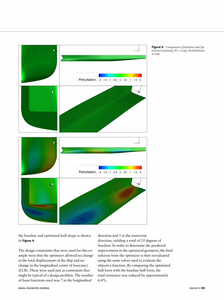
the baseline and optimized hull shape is shown
in Figure 4.
The design constraints that were used for this ex-
ample were that the optimizer allowed no change
in the total displacement of the ship and no
change in the longitudinal center of buoyancy
(LCB). These were used just as constraints that
might be typical of a design problem. The number
of basis functions used was 7 in the longitudinal
direction and 5 in the transverse
direction, yielding a total of 35 degrees of
freedom. In order to determine the predicted
improvement in the optimized geometry, the final
solution from the optimizer is then reevaluated
using the same solver used to evaluate the
objective function. By comparing the optimized
hull form with the baseline hull form, the
total resistance was reduced by approximately
6.4%.
Figure 4: Comparison of Baseline and Op-timized Geometry (Fr 5 0.29), Perturbationsin Feet
NAVAL ENGINEERS JOURNAL 2010 #2 &59
JHSSBowShapeOptimization (InitialGeometry5BaselineBulb)In this case, the optimization procedure was
limited to only focus on the bow section. The
initial intent of performing this study was to
compare an optimization process for determin-
ing the best bow shape to what was
experimentally observed from the several bow
variants that were tested with physical models.
The single objective function optimization was
performed for three separate speeds (20, 30, and
40 knots or 10.3, 15.5, and 20.6 m/s) corre-
sponding to Froude numbers of 0.193, 0.290,
and 0.386. This would provide an optimum for
several speeds around the design speed of
36 knots.
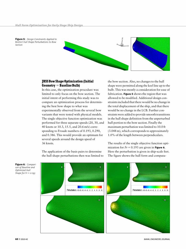
The application of the basis pairs to determine
the hull shape perturbations then was limited to
the bow section. Also, no changes to the hull
shape were permitted along the keel line up to the
bulb. This was mostly a consideration for ease of
fabrication. Figure 5 shows the region that was
allowed to be modified. Additional design con-
straints included that there would be no change in
the total displacement of the ship, and that there
would be no change in the LCB. Further con-
straints were added to provide smooth transitions
in the hull shape definition from the unperturbed
hull portion to the bow section. Finally the
maximum perturbation was limited to 10.0 ft
(3.048 m), which corresponds to approximately
1.0% of the length between perpendiculars.
The results of the single objective function opti-
mization for Fr 5 0.193 are given in Figure 6.
Here the perturbation is given in ship-scale feet.
The figure shows the hull form and computa-
Figure 5: Design Constraints Applied toRestrict Hull Shape Perturbations to BowSection
Figure 6: Compari-son of Baseline andOptimized HullShape for Fr 5 0.193
NAVAL ENGINEERS JOURNAL60& 2010 #2
Hull Form Optimization for Early Stage Ship Design
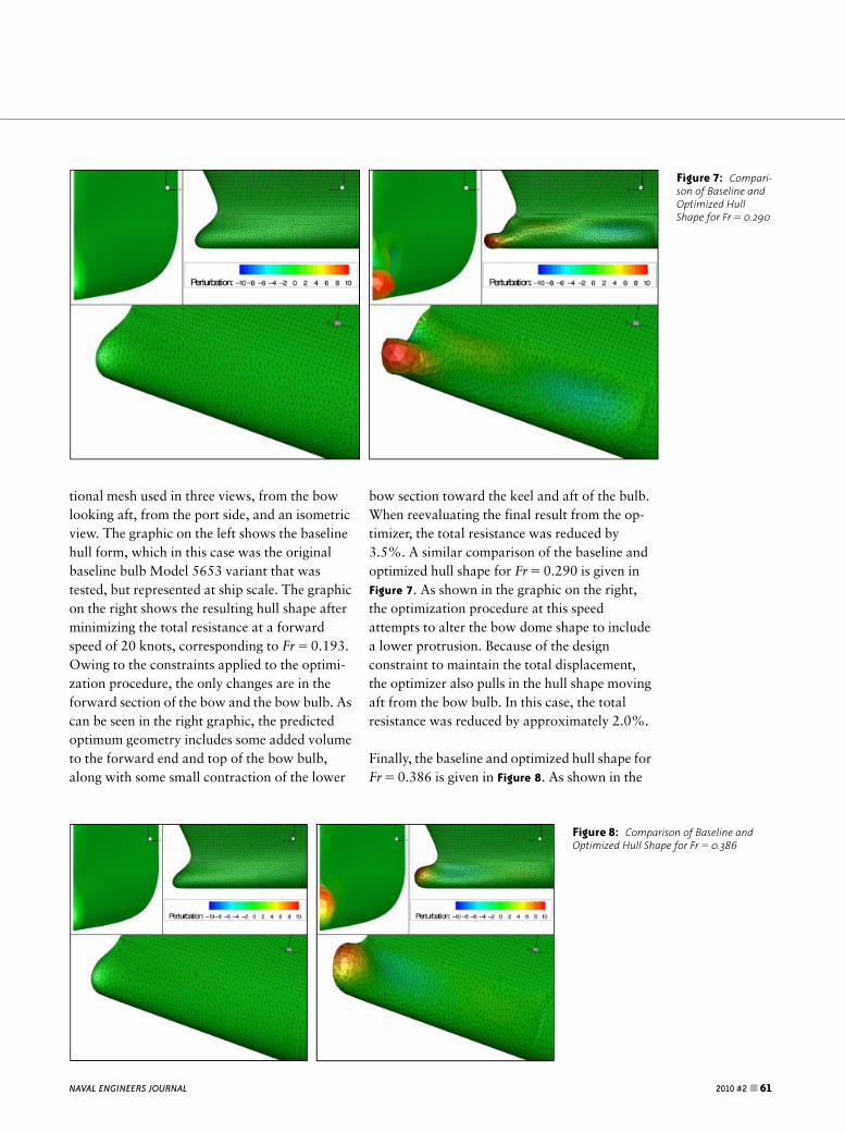
tional mesh used in three views, from the bow
looking aft, from the port side, and an isometric
view. The graphic on the left shows the baseline
hull form, which in this case was the original
baseline bulb Model 5653 variant that was
tested, but represented at ship scale. The graphic
on the right shows the resulting hull shape after
minimizing the total resistance at a forward
speed of 20 knots, corresponding to Fr 5 0.193.
Owing to the constraints applied to the optimi-
zation procedure, the only changes are in the
forward section of the bow and the bow bulb. As
can be seen in the right graphic, the predicted
optimum geometry includes some added volume
to the forward end and top of the bow bulb,
along with some small contraction of the lower
bow section toward the keel and aft of the bulb.
When reevaluating the final result from the op-
timizer, the total resistance was reduced by
3.5%. A similar comparison of the baseline and
optimized hull shape for Fr 5 0.290 is given in
Figure 7. As shown in the graphic on the right,
the optimization procedure at this speed
attempts to alter the bow dome shape to include
a lower protrusion. Because of the design
constraint to maintain the total displacement,
the optimizer also pulls in the hull shape moving
aft from the bow bulb. In this case, the total
resistance was reduced by approximately 2.0%.
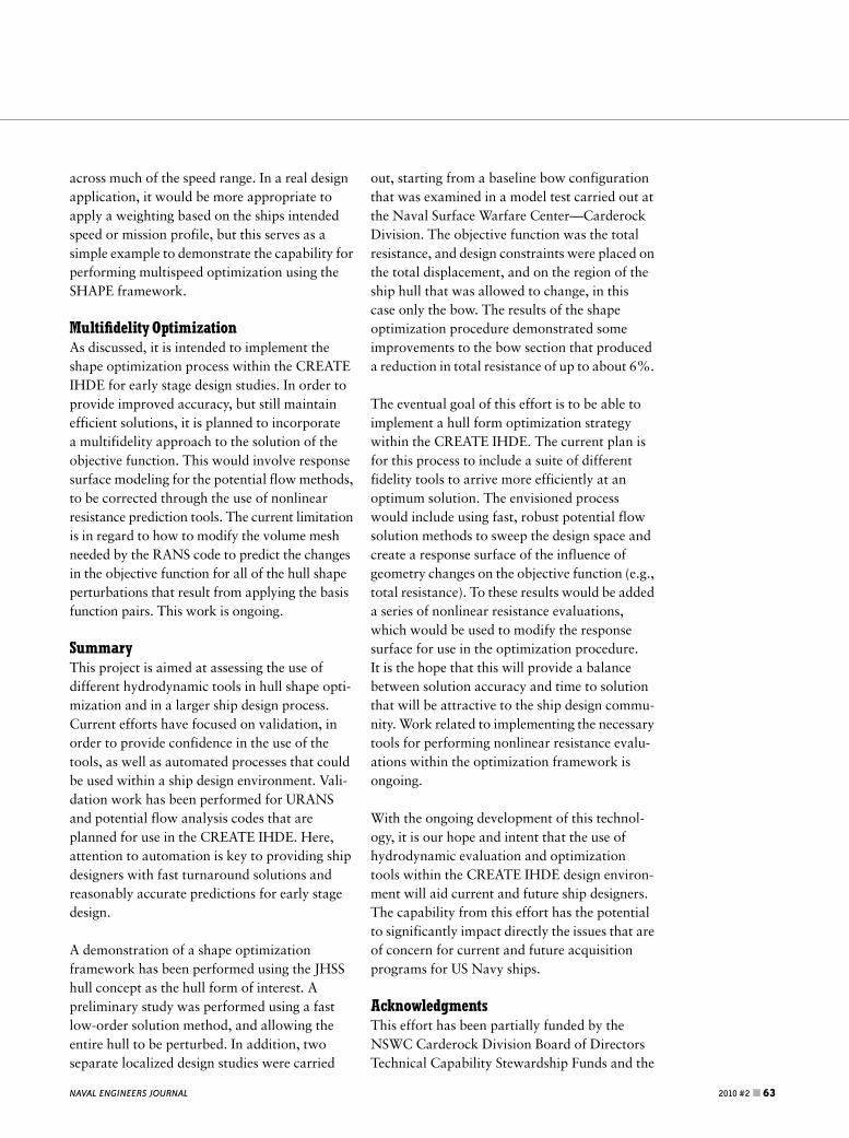
Finally, the baseline and optimized hull shape for
Fr 5 0.386 is given in Figure 8. As shown in the
Figure 7: Compari-son of Baseline andOptimized HullShape for Fr 5 0.290
Figure 8: Comparison of Baseline andOptimized Hull Shape for Fr 5 0.386
NAVAL ENGINEERS JOURNAL 2010 #2 &61

graphic on the right, there is a continuation of
the trend toward adding volume to the forward
end and top portion of the bulb. In this case,
when the optimized hull shape was reevaluated
using TSD in the fast mode, the total resistance
increased just slightly by approximately
10.02%. What this means is that the improved
hull shape determined by the optimizer turned
out to not be an improved design when
reevaluated by the solver. This is why the re-
evaluation step is so important when evaluating
the designs that are generated. It is also likely
that the constraint on the LCB is overly
constraining the optimization process, as it is
difficult to optimize a small bow region without
allowing this to change.
At this point, some comments regarding the
number of basis functions used are warranted.
Recall that in the previous total ship optimiza-
tion example, a total of 35 basis functions were
used. In many cases, this is found to be a suffi-
cient number to examine the changes to the
design. Generally speaking, one expects to find
that the improvements to the baseline design
should increase with increasing degrees of free-
dom, assuming the same constraints are used. In
many cases, diminishing returns are observed
from going to higher numbers of basis functions,
due to decreasing impacts from shorter length
scales. In the present bow shape optimization
example, however, it was found that much
better behavior was found by increasing the
number of degrees of freedom. In this case,
the number of basis functions used for
Fr 5�0.193 was 8 (longitudinal) and 6 (trans-
verse) for a total of 48 degrees of freedom. The
Fr 5 0.29 optimization used 8�7 (total of 56)
and the Fr 5 0.386 optimization used 8�4 (total
of 32).
Without additional testing of the resulting opti-
mized shapes, we cannot make any definitive
judgment as to the magnitude of the reduction in
resistance. But all of this has proved to be a use-
ful demonstration of this type of capability and
the potential to incorporate shape optimization
tools within the IHDE.
MultispeedOptimizationAnother caution in performing design optimiza-
tions for ships is that there can be significant
dependence on the speed for which the design is
optimized. In other words, a hull that is opti-
mized for a single objective function at a given
speed may perform much worse when at speeds
other than the design speed. This is illustrated in
Figure 9 that shows the predicted total resistance
normalized by the total resistance of the baseline
hull shape for each of the single speed optimized
hull forms as a function of Froude number. In
this example, the global constraints related to
changes in the displacement and changes in the
LCB have been removed.
As shown in Figure 9, the performance of the
hull shapes that are optimized based on a single
speed, perform very well at the speed at which
they were optimized. Moving away from those
speeds, however, can cause a significant degra-
dation in the performance. This is particularly
true when examining the hulls optimized at
Fr 5 0.29 and Fr 5 0.386 at the lower speed
range (Fro0.2). Also shown in Figure 9 are the
predicted normalized total resistance evalua-
tions for a hull shape that was determined by
using multiple speeds in evaluating the objective
function. In this example, the three speeds were
given weights of 0.5, 0.25, and 0.25 for the
Fr 5 0.193, 0.290, and 0.386 conditions,
respectively. As indicated in the figure, this mul-
tispeed optimized hull shape performs quite well
Froude Number
To
tal R
esis
tan
ce N
orm
aliz
ed b
y B
asel
ine
0.1 0.15 0.2 0.25 0.3 0.35 0.4 0.450.85
0.9
0.95
1
1.05
1.1
1.15
1.2
1.25Figure 9: TotalResistanceNormalized byBaseline versusFroude Number
NAVAL ENGINEERS JOURNAL62 &2010 #2
Hull Form Optimization for Early Stage Ship Design
across much of the speed range. In a real design
application, it would be more appropriate to
apply a weighting based on the ships intended
speed or mission profile, but this serves as a
simple example to demonstrate the capability for
performing multispeed optimization using the
SHAPE framework.
Multi¢delity OptimizationAs discussed, it is intended to implement the
shape optimization process within the CREATE
IHDE for early stage design studies. In order to
provide improved accuracy, but still maintain
efficient solutions, it is planned to incorporate
a multifidelity approach to the solution of the
objective function. This would involve response
surface modeling for the potential flow methods,
to be corrected through the use of nonlinear
resistance prediction tools. The current limitation
is in regard to how to modify the volume mesh
needed by the RANS code to predict the changes
in the objective function for all of the hull shape
perturbations that result from applying the basis
function pairs. This work is ongoing.
SummaryThis project is aimed at assessing the use of
different hydrodynamic tools in hull shape opti-
mization and in a larger ship design process.
Current efforts have focused on validation, in
order to provide confidence in the use of the
tools, as well as automated processes that could
be used within a ship design environment. Vali-
dation work has been performed for URANS
and potential flow analysis codes that are
planned for use in the CREATE IHDE. Here,
attention to automation is key to providing ship
designers with fast turnaround solutions and
reasonably accurate predictions for early stage
design.
A demonstration of a shape optimization
framework has been performed using the JHSS
hull concept as the hull form of interest. A
preliminary study was performed using a fast
low-order solution method, and allowing the
entire hull to be perturbed. In addition, two
separate localized design studies were carried
out, starting from a baseline bow configuration
that was examined in a model test carried out at
the Naval Surface Warfare Center—Carderock
Division. The objective function was the total
resistance, and design constraints were placed on
the total displacement, and on the region of the
ship hull that was allowed to change, in this
case only the bow. The results of the shape
optimization procedure demonstrated some
improvements to the bow section that produced
a reduction in total resistance of up to about 6%.
The eventual goal of this effort is to be able to
implement a hull form optimization strategy
within the CREATE IHDE. The current plan is
for this process to include a suite of different
fidelity tools to arrive more efficiently at an
optimum solution. The envisioned process
would include using fast, robust potential flow
solution methods to sweep the design space and
create a response surface of the influence of
geometry changes on the objective function (e.g.,
total resistance). To these results would be added
a series of nonlinear resistance evaluations,
which would be used to modify the response
surface for use in the optimization procedure.
It is the hope that this will provide a balance
between solution accuracy and time to solution
that will be attractive to the ship design commu-
nity. Work related to implementing the necessary
tools for performing nonlinear resistance evalu-
ations within the optimization framework is
ongoing.
With the ongoing development of this technol-
ogy, it is our hope and intent that the use of
hydrodynamic evaluation and optimization
tools within the CREATE IHDE design environ-
ment will aid current and future ship designers.
The capability from this effort has the potential
to significantly impact directly the issues that are
of concern for current and future acquisition
programs for US Navy ships.
AcknowledgmentsThis effort has been partially funded by the
NSWC Carderock Division Board of Directors
Technical Capability Stewardship Funds and the
NAVAL ENGINEERS JOURNAL 2010 #2 &63

Department of Defense High Performance
Computing Modernization Program under the
CREATE Ships Hydrodynamics Project. The
authors also would like to thank John Kuhn
from SAIC, who is the developer of the SHAPE
code.
ReferencesCampana, E.F., D. Peri, Y. Tahara, M. Kandasamy, and
F. Stern, ‘‘Numerical optimization methods for ship
hydrodynamic design,’’ Proceedings of the SNAME
2009 Annual Meeting & Expo, Providence, RI, October
21–23, 2009.
Campana, E.F., D. Peri, Y. Tahara, M. Kandasamy, F. Stern,
C. Cary, R. Hoffman, J. Gorski, and C. Kennell, ‘‘Simula-
tion-based design of fast multihull ships,’’ Proceedings
of the 26th Symposium on Naval Hydrodynamics,
Rome, Italy, September 17–22, 2006.
Cusanelli, D., ‘‘Joint high speed sealift (JHSS) baseline
shaft & strut (model 5653) series 1: bare hull resis-
tance, appended resistance, and alternative bow
evaluations,’’ Naval Surface Warfare Center CarderockDivision technical report NSWCCD-50-TR-2006/064,
December 2006.
Kuhn, J., K. Chevalier, E. Schlageter, C. Scragg, andD. Wyatt, ‘‘The use of linear programming and basis
functions for hull-form optimization,’’ 9th International
Conference on Numerical Ship Hydrodynamics, Ann
Arbor, MI, August 5–8, 2007.
Metcalf, B., J. Grabeel, G. Karafiath, D. Hendrix, and
F. Noblesse, ‘‘Rapid resistance evaluation of
high-speed ships,’’ Naval Surface Warfare Center –
Carderock Division technical digest, April 2004.
Noblesse, F., ‘‘A slender-ship theory of wave resistance,’’
Journal of Ship Research, Vol. 27, pp. 13–33, 1983.
Stern, F., P.M. Carrica, M. Kandasamy, J. Gorski, J. O’Dea,M. Hughes, R. Miller, D. Hendrix, D. Kring, W. Milewski,
R. Hoffman, and C. Cary, ‘‘Computational hydrody-
namic tools for high-speed transports,’’ Transactions of
Society of Naval Architects and Marine Engineers,
Vol. 114, pp. 55–81, 2007.
Wilson, W., J. Gorski, M. Kandasami, T. Takai, F. Stern,
and Y. Tahara, ‘‘Hydrodynamic shape optimization for
naval vehicles,’’ Proceedings of the 2009 High Perfor-
mance Computing Modernization Program (HPCMP)
Users Group Conference, San Diego, CA, June 15–18,
2009.
AuthorBiographiesMr. Wesley Wilson is an engineer in the Compu-
tational Hydromechanics Division at the Naval
Surface Warfare Center – Carderock Division,
West Bethesda, Maryland. He received a B.S. in
Engineering-Physics from West Virginia Wesle-
yan College in 1997 and an M.S. in Mechanical
Engineering from West Virginia University in
1999. Mr. Wilson has been active in the field of
computational fluid dynamics (CFD) for the
past 14 years, with research areas focused on
surface ship and submarine hydrodynamics,
ballast water exchange, hull form design, and
shape optimization. e-mail: wesley.m.wilson@
navy.mil
Dr. Dane Hendrix has been employed by the US
Navy since 1984–at the David Taylor Model
Basin for 25 years and then at NAVSEA
Headquarters. He holds a B.S. degree in Naval
Architecture and Marine Engineering from
Webb Institute (1984) and an M.M.E. degree
from Catholic University (1987). In 1995, he
received his Ph.D. from the University of
Maryland in Mechanical Engineering. His areas
of interest are primarily in free-surface and wake
hydrodynamics and hull form design.
Dr. Hendrix is with the Carderock Division,
Naval Surface Warfare Center, West Bethesda,
Maryland.
Dr. Joseph Gorski is Head of the Computational
Hydromechanics Division at the Naval Surface
Warfare Center, Carderock Division (NSWCCD),
West Bethesda, Maryland, which is responsible
for a wide variety of computational work that
supports the fluids related design, analysis, and
modification of US Navy ships, submarines,
propulsors, and auxiliary systems. Previously,
Dr. Gorski was Head of the Propulsion and
Fluid Systems Division at NSWCCD, which
maintained the Navy’s core capability to design
propulsors for ships and submarines. Dr. Gorski
received a B.S. in Engineering Science (honors
program) and an M.S. in Aerospace Engineering
from The Pennsylvania State University. In 1993
Dr. Gorski received a Ph.D. in Mechanical
Engineering from the University of Maryland.
NAVAL ENGINEERS JOURNAL64 &2010 #2
Hull Form Optimization for Early Stage Ship Design

Dr. Gorski is the current chairman of the 26th
International Towing Tank Committee on
Resistance. He is the author/coauthor of over 80
technical publications and was awarded the
Rear Admiral David W. Taylor Award for
outstanding scientific achievement in advancing
high-end computational efforts in the U.S. Navy
maritime community.
NAVAL ENGINEERS JOURNAL 2010 #2 &65