humanoid robot: design and fuzzy logic control technique for its
TRANSCRIPT

1
Humanoid Robot: Design and Fuzzy Logic Control
Technique for Its Intelligent Behaviors
Elmer P. Dadios, Jazper Jan C. Biliran, Ron-Ron G. Garcia, D. Johnson, and Adranne Rachel B. Valencia
De La Salle University, Manila, Philippines
1. Introduction
A humanoid robot is a robot with its overall appearance based on that of the human body
[1]. In general humanoid robots have a torso with a head, two arms and two legs, although
some forms of humanoid robots may model only part of the body, for example, the upper
torso. Some humanoid robots may also have a face with eyes and mouth equip with facial
interfaces [2, 3, 4, 5]. A humanoid robot is autonomous because it can adapt to changes in its
environment or itself and continue to reach its goal [6]. This is the main difference between
humanoids and other kinds of robots, like industrial robots, which are used to performing
tasks in highly structured environments.
Humanoid robots are created to imitate some of the same physical and mental tasks that
humans undergo daily [7]. Scientists and specialists from many different fields including
engineering, cognitive science, and linguistics combine their efforts to create a robot as
human-like as possible [8, 9]. Their creators' goal for the robot is that for it to both
understand human intelligence, reason and act like humans [7]. If humanoids are able to do
so, they could eventually work alongside with humans.
There are many issues involves in developing a humanoid robot [1, 10, 11]. But the most
difficult is balancing the robot while it does its motion. Babies take several months before
they learn to walk; one reason is the gravity affecting our body weight. Like humans, robots
also have gravitational force affecting on it. This is the reason why conducting research in
this field is still very challenging and exciting [14.15].
The next section of this chapter is organized as follows: section 2 discusses the physical
design of the robot. This involves the design and development of mechanical structure of
the robot. Section 3 presents the sensors that are use for gathering environment information.
The inputs from these sensors are used for robot perception and intelligence. Section 4
discusses the power needed to fully operate the humanoid robot. Section 5 discusses the
microcontroller used that does the control execution and operation of the robot. Section 6
discusses the fuzzy logic algorithm developed for the total intelligence and control of the
www.intechopen.com

Fuzzy Logic – Controls, Concepts, Theories and Applications
4
robot. Section 7 present the experiment results conducted in this research. Discussions and
analysis of these results are also presented in this section. Finally, section 8 presents the
conclusion and recommendations for future work.
2. The humanoid robot mechanical design
The physical structure of the robot developed in this research is shown in figure 1. It has 17
degrees of freedom. Hence, it utilizes 17 servomotors as its actuators to perform its dynamic
motions. There are 10 motors employed for the legs, 6 motors for the arms, and 1 motor for
the head. The servo motor used in this research requires 3-5 Volts peak-to-peak square wave
pulse. Pulse duration is from 0.9ms to 2.1ms with 1.5 ms as center. The pulse refreshes at 50
Hz (20ms). It is operated with a 4.8-6.0 Volts.
Fig. 1. Skeletal design of the humanoid robot with 17 degrees of freedom.
www.intechopen.com

Humanoid Robot: Design and Fuzzy Logic Control Technique for Its Intelligent Behaviors
5
The arrangement or position of the motors is crucial for the movement of the robot. The
motors are connected to each other using aluminum brackets. Design for the aluminum
brackets for the arm and legs follow the movements set for the motor. Each bracket is
capable of tilting to the left and right for the rotational span allowed by the servo motor.
Each aluminum bracket has multiple holes for connecting plates and brackets to one
another. The brackets also act as the shield that protects the servo motor and robust enough
to avoid damage when it falls. Despite of its rigidity, the bracket material should be lighter
and can carry the servo motors as well as the total load of the robot including its circuitry.
The body of the robot is made of a durable acrylic plastic case and is used to protect the
control board and circuitry from damage. Several factors were considered in the design of
the body casing. The dimensions of the casing were designed to accommodate the IC power
battery and the microcontroller. It is also important for the body case to be proportional to
the dimensions of the legs and the arms of the robot.
3. The sensors used for the humanoid robot intelligence
The sensors are needed by the robot to gather information about the conditions of the
environment to allow the robot to make necessary decisions about its position or certain
actions that the situation requires. In this research, four types of sensors are utilized: infrared
and ultrasonic sensors for obstacle detection, tilt sensor for robot balancing, and color sensor
for ball recognition. Details of the position of these sensors are shown in figure 2.
Fig. 2. The Humanoid Robot with sensors locations.
www.intechopen.com
Fuzzy Logic – Controls, Concepts, Theories and Applications
6
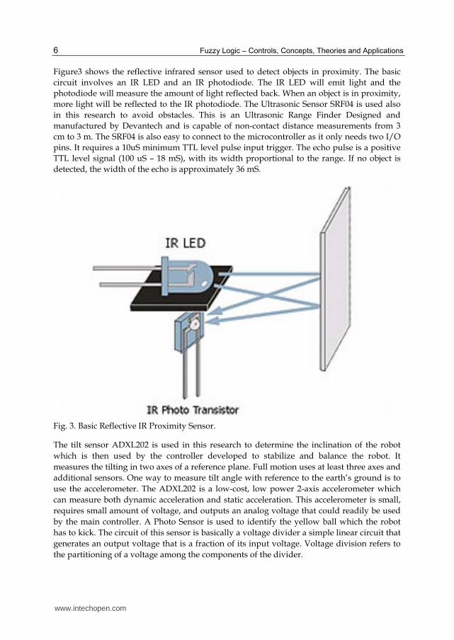
Figure3 shows the reflective infrared sensor used to detect objects in proximity. The basic
circuit involves an IR LED and an IR photodiode. The IR LED will emit light and the
photodiode will measure the amount of light reflected back. When an object is in proximity,
more light will be reflected to the IR photodiode. The Ultrasonic Sensor SRF04 is used also
in this research to avoid obstacles. This is an Ultrasonic Range Finder Designed and
manufactured by Devantech and is capable of non-contact distance measurements from 3
cm to 3 m. The SRF04 is also easy to connect to the microcontroller as it only needs two I/O
pins. It requires a 10uS minimum TTL level pulse input trigger. The echo pulse is a positive
TTL level signal (100 uS – 18 mS), with its width proportional to the range. If no object is
detected, the width of the echo is approximately 36 mS.
Fig. 3. Basic Reflective IR Proximity Sensor.
The tilt sensor ADXL202 is used in this research to determine the inclination of the robot
which is then used by the controller developed to stabilize and balance the robot. It
measures the tilting in two axes of a reference plane. Full motion uses at least three axes and
additional sensors. One way to measure tilt angle with reference to the earth’s ground is to
use the accelerometer. The ADXL202 is a low-cost, low power 2-axis accelerometer which
can measure both dynamic acceleration and static acceleration. This accelerometer is small,
requires small amount of voltage, and outputs an analog voltage that could readily be used
by the main controller. A Photo Sensor is used to identify the yellow ball which the robot
has to kick. The circuit of this sensor is basically a voltage divider a simple linear circuit that
generates an output voltage that is a fraction of its input voltage. Voltage division refers to
the partitioning of a voltage among the components of the divider.
www.intechopen.com

Humanoid Robot: Design and Fuzzy Logic Control Technique for Its Intelligent Behaviors
7
The Photo Sensor circuit component is a photoresistor or an LDR (Light Dependent Resistor) in series with a fixed resistor. The LDR must be a part of a voltage divider circuit in order to give an output voltage which varies with illumination. The super bright light emitting diode will provide the light to the LDR. When an object is placed in front of the LDR and LED at about 10-20mm away, some of the light will reflect back to the LDR, depending on the material. A material with a bright color will reflect more light to the LDR. A black material will absorb all the light and nothing will be reflected. In this project, the robot needs to detect a yellow ball for it to kick. The disadvantage with the circuit presented is that it will also detect a material brighter than yellow. However, the scope of this project is only to detect the yellow ball, and not to differentiate it from other colors.
4. Power management and power source
Power management is an essential part of the humanoid robot. This part functions to ensure that the proper voltage is supplied to the servos as well as the sensors and the microcontroller. There are circumstances where in the power supplied to the motors exceeds the power required. In cases like this, probable damage could occur. That is why it is essential to have the voltage regulated.
For voltage regulation, the LM338k transistor was used as the primary part of the regulator circuit. The primary choice would have been the LM7805, which is the most widely used transistor. It supplies 5 volts and is capable of generating 1 to 1.5 A of current. However, with the number of motors used in this project, the current rating of the LM7805 would be insufficient. Hence, the LM338k was opted due to its higher current rating at about 1 to 5 Amperes, ensuring that ample amount of current is supplied to the motors.
There are six outputs in the circuit for the servo motors. Four voltage regulators were used to accommodate 24 motors. Only 17 motors were used but additional outputs were added to accommodate the sensors and other additions. The output voltage can be solved using the formula
Vo = Vref + (1 + R2/R1) + IadjR2 (1)
An output of 5.9 volts is desired so R2 is set at 450 ohms, and R1, which is constant, is 120 ohms. Vref = 1.25 and Iadj = 50uA.
Substituting,
Vo = 1.25(1+450/120) + 50uA(340) (2)
the value of Vo is obtained.
Vo = 5.95 V (3)
This research utilizes packed 7.2 volt Lithium Ion Batteries as the power source of the robot. It would then be regulated to approximately 5.9 volts. Lithium Ion batteries are light weight which is a big factor for this project considering the size and the movements needed to be performed by the robot. NiMH batteries (Nickel Metal Hydrite) were also an option but to be able to supply the required voltage needed by the robot, the battery has to be customized, which made the batteries bulky and heavy. Litihium Ion Batteries were also readily available.
www.intechopen.com

Fuzzy Logic – Controls, Concepts, Theories and Applications
8
5. The microcontroller: Robot brain
The Atmega128 microcontroller used in this research serves as the main controller of the entire system. It is in-charge for processing all the input data and output data needed by the robot. Input data refers to the information taken from all the sensors and control switches. Output data are the signals needed by the servo motors in order to provide proper results in different situations for robot actions. Being the only microcontroller in the system, information from all modules is all carried in and out from this single controller. These modules are: the power management unit, the sensor information unit, the servo motor control unit, the artificial intelligence unit, and the central control unit.
The power management unit is the one responsible for distributing and monitoring the power to the entire system supplied by the batteries. If one of these batteries reaches critical level, the power management unit updates the microcontroller about the situation so that the microcontroller will be able to decide if the robot should continue its task or should stop.
The sensor information unit is responsible for all the system inputs of the robot. All of these inputs are fed into the microcontroller and then processed to provide the robot appropriate action for every situation.
The servo motor control unit is responsible for providing signals for each servo motor of the robot. Timing is considered an important factor in this module unlike all other modules where timing is not as important. One problem encountered in this research was that it would be difficult to control all motors from the output port pins of the microcontroller. Because of this problem, several approaches were considered. Using a separate microcontroller was first considered for controlling all the 17 servo motors. But using another microcontroller just for controlling the servo motors will defeat the purpose of using just one microcontroller for the whole system and will only pose new problems for the whole system like the communication and synchronization of the two microcontrollers. The solution was to make use of the Atmega128’s timer/counter and connect the 17 servo motors to two 4017 decade counters.
The central control unit is responsible for the main controls of the robot. This module is a switch panel consists of a power supply switch, a reset switch, and 8 action switches. All batteries are connected to the power supply switch which turns the robot on and off. The reset switch is a normally open tact switch that is connected to the active low reset pin of the microcontroller and ground. The action switches determine what action the robot will be performing. These switches are connected to the 8 external interrupt pins of the microcontroller which are configured as level triggered, meaning the interrupt will trigger once the switch is held low. Also, these external interrupts INT0-INT7 have priority levels. INT0 being the most prioritized and INT7 as least prioritized interrupt.
6. The robot intelligence: Fuzzy logic system
The Fuzzy Logic System module is used for the artificial intelligence control algorithm of the robot. This module is responsible for the stability and balancing of the robot while it is performing actions such as walking and kicking. Implementation of fuzzy logic is inside the microcontroller software which is modifiable and adjustable. Since the implementation is in software, this procedure is processed inside the microcontroller in which the input values are taken from the tilt sensor and the output values provide the servo motors correct positions.
www.intechopen.com

Humanoid Robot: Design and Fuzzy Logic Control Technique for Its Intelligent Behaviors
9
Fuzzy logic is a problem-solving control system methodology that mimics how humans
derive a conclusion based on vague, ambiguous, imprecise, noisy or missing input
information [12, 13]. The general idea about fuzzy logic is that it takes the inputs from the
sensors which is a crisp value and transforms it into membership values ranging from 0 to 1.
It then undergoes fuzzy reasoning process using the obtained membership values with the
set of rules created. From the previous process, the system obtains a fuzzy set that will be
transformed back to crisp values which controls the servo motors [12, 13]. Fuzzy logic
systems are capable of processing inexact data and produce acceptable outputs. In addition,
there is no need for very complex mathematical computations to control the robot. Also, the
physical design of the robot does not need to be very exact and complicated as the fuzzy
logic system can compensate for these flaws. Since the fuzzy logic is implemented using
software, adjustments in the system is easier, cheaper and additional space is not needed
which will only mean additional weight to the robot.
Two fuzzy logic system (FLS) controllers are developed in this research for the robot’s
balancing and stability. One FLS controls the left and right tilt and the other FLS controls the
forward and backward tilt. Tilt angle in the first fuzzy logic system, which is for the left and
right tilt, is taken and processed. Then the second fuzzy logic system will do the same with
the forward and backward tilt angle. The idea is to operate the two fuzzy logic systems
independently. This approach is more advantageous in terms of software implementation
and complexity of the entire fuzzy logic system.
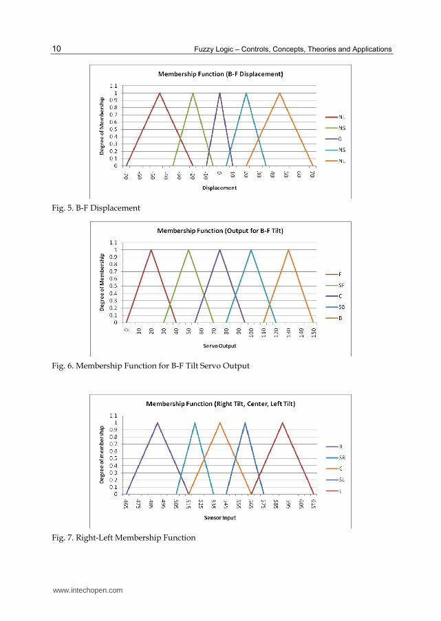
The Mamdani’s method was used for implementing the fuzzy logic systems because of its
simple yet great composition of ‘min-max’ operations [16]. Sample membership functions
are shown in figures 4 to 9. Tables 1 and 2 shows the fuzzy associative memory matrix of the
2 fuzzy logic systems with the corresponding rules. Tables 3 and 4 show the final output on
deciding what motors to activate. The idea is all the affected motors are going to increase or
decrease their current angle until the system becomes stable. The amount of the angle shift
will depend on the position of the motor in the robot. Observably, change in the angle of the
motors located near the ground will have greater effect to the whole body than motors
located less near the ground.
Fig. 4. Backward-Forward Membership Function
www.intechopen.com
Fuzzy Logic – Controls, Concepts, Theories and Applications
10
Fig. 5. B-F Displacement
Fig. 6. Membership Function for B-F Tilt Servo Output
Fig. 7. Right-Left Membership Function
www.intechopen.com

Humanoid Robot: Design and Fuzzy Logic Control Technique for Its Intelligent Behaviors
11
Fig. 8. R-L Displacement
Fig. 9. Membership Function for R-L Tilt Servo Output
FLC 1 Displacement
NL NS 0 PS PL
B-F
Til
t
B F F F
SB SF SF F
C C C C C C
SF B SB SB
F B B B
Table 1. Fuzzy Logic Controller (FLC) 1 FAM
B – backward
F – forward
www.intechopen.com

Fuzzy Logic – Controls, Concepts, Theories and Applications
12
R - right
L - left
C - center
SB - slightly backward
SF - slightly forward
SR - slightly right
SL - slightly left
NL - negative large
NS - negative small
0 (zero) - negligible
PS - positive small
PL - positive large
RULES for (FLC) 1
1. if tilt is B and delta x is 0 (zero) then output is F. 2. if tilt is B and delta x is PS then output is F. 3. if tilt is B and delta x is PL then output is F. 4. if tilt is SB and delta x is 0 (zero) then output is SF. 5. if tilt is SB and delta x is PS then output is SF. 6. if tilt is SB and delta x is PL then output is F. 7. if tilt is C and delta x is NL then output is C. 8. if tilt is C and delta x is NS then output is C. 9. if tilt is C and delta x is 0 (zero) then output is C. 10. if tilt is C and delta x is PS then output is C. 11. if tilt is C and delta x is PL then output is C. 12. if tilt is SF and delta x is NL then output is B. 13. if tilt is SF and delta x is NS then output is SB. 14. if tilt is SF and delta x is 0 (zero) then output is SB. 15. if tilt is F and delta x is NL then output is B. 16. if tilt is F and delta x is NS then output is B. 17. if tilt is F and delta x is 0 (zero) then output is B.
FLC 2 Displacement
NL NS 0 PS PL
R-L
Til
t
R L L L
SR SL SL L
C C C C C C
SL R SR SR
L R R R
Table 2. Fuzzy Logic Controller (FLC) 2 FAM
www.intechopen.com

Humanoid Robot: Design and Fuzzy Logic Control Technique for Its Intelligent Behaviors
13
RULES for (FLC) 2
1. if tilt is R and delta x is 0 (zero) then output is L. 2. if tilt is R and delta x is PS then output is L. 3. if tilt is R and delta x is PL then output is L. 4. if tilt is SR and delta x is 0 (zero) then output is SL. 5. if tilt is SR and delta x is PS then output is SL. 6. if tilt is SR and delta x is PL then output is L. 7. if tilt is C and delta x is NL then output is C. 8. if tilt is C and delta x is NS then output is C. 9. if tilt is C and delta x is 0 (zero) then output is C. 10. if tilt is C and delta x is PS then output is C. 11. if tilt is C and delta x is PL then output is C. 12. if tilt is SL and delta x is NL then output is R. 13. if tilt is SL and delta x is NS then output is SR. 14. if tilt is SL and delta x is 0 (zero) then output is SR. 15. if tilt is L and delta x is NL then output is R. 16. if tilt is L and delta x is NS then output is R. 17. if tilt is L and delta x is 0 (zero) then output is R.
Having established these two fuzzy logic systems, the balancing task will entirely depend
on these. Failure to one of these systems would mean failure to the entire balancing task of
the robot.
Output Affected Motor
L 1,2,3,4,5,6,7,8
SL 1,2,3,4,5,6,7,8
C None
SR 1,2,3,4,5,6,7,8
R 1,2,3,4,5,6,7,8
Table 3. Fuzzy Logic System R-L Output
Output Affected Motor
F 3,4,7,8
SF 3,4,7,8
C None
SB 3,4,7,8
B 3,4,7,8
Table 4. Fuzzy Logic System B-F Output
7. Experiment results
7.1 Inclined steel plate balancing experiments
In this experiment, a steel plate platform was used to measure the balancing capability of
the robot. One end of the platform was gradually elevated so that the robot is standing on
an inclined plane and the maximum angle the robot can stay on standing position is
www.intechopen.com

Fuzzy Logic – Controls, Concepts, Theories and Applications
14
recorded. Figures 10-13 shows the sample results of the real and physical experiments
conducted. It can be seen in this figure that the robot uses its left foot to maintain its balance
that compensate the angle taken on the inclined plane.
There were 4 tests of experiments conducted based on actual position of the robot relative to
the inclined plane. The first test was the robot facing right of elevated steel plate as shown in
figure 7. The second test was the robot facing left of the inclined steel plate as shown in
figure 8. The third was the robot facing front of the inclined steel plate as shown in figure 9.
And the fourth was the robot facing back of the inclined steel plate as shown in figure 10. It
can be seen from these pictures that the robot uses its foot and body to maintain its stability.
Figures 14a and 14b shows the results of these experiments with a comparison of the
performance of the fuzzy logic controller against the conventional controller. Clearly from
these results we can see the superiority of the fuzzy logic controller developed.
Fig. 10. Robot Inclined Steel Plate Balancing Experiment. Right position. Note that the hand of the person is not touching the robot. This is just in preparation to catch the robot when it falls.
Fig. 11. Robot Inclined Steel Plate Balancing Experiment. Left position. Note that the hand of the person is not touching the robot. This is just in preparation to catch the robot when it falls.
www.intechopen.com

Humanoid Robot: Design and Fuzzy Logic Control Technique for Its Intelligent Behaviors
15
Fig. 12. Robot Inclined Steel Plate Balancing Experiment. Back position. Note that the hand of the person is not touching the robot. This is just in preparation to catch the robot when it falls.
Fig. 13. Robot Inclined Steel Plate Balancing Experiment. Front position. Note that the hand of the person is not touching the robot. This is just in preparation to catch the robot when it falls.
Fig. 14a. Humanoid robot steel plate balancing performance with fuzzy logic controller
www.intechopen.com

Fuzzy Logic – Controls, Concepts, Theories and Applications
16
Fig. 14b. Humanoid robot steel plate balancing performance without fuzzy logic controller
7.2 Ball kicking experiments
The humanoid robot developed in this research can identify and kick a yellow tennis ball. A photo sensor is installed on the foot of the robot. Once the sensor found the ball the robot position itself to do the kicking. Complete animation of this task is shown in figure 15.
Fig. 15. Ball kicking experiment results
www.intechopen.com

Humanoid Robot: Design and Fuzzy Logic Control Technique for Its Intelligent Behaviors
17
The robot uses its arm to balance itself in addition to its body alignment. Figure 16 shows the statistics of the robot performance in kicking the ball. The average distance the ball travel after kicking is 14.6 inches. Clearly from this figures the robot is very stable and reliable in performing this motions.
Fig. 16. Humanoid robot ball kicking controller performance.
7.3 Obstacle avoidance experiments
The robot uses ultrasonic and infra red sensors to detect the obstacles on its path. The positions of these sensors are evenly distributed on the robot’s body. It is at the right, left, and center positions. When only the right sensor detects the obstacle the robot will do left side step motions until no obstacle is found. When only the left sensor detects the obstacle the robot will do right side steps motions until no obstacle is found. When all three ultrasonic sensors detect obstacle the robot will stop. If there are no more obstacles found the robot will walk forward right away. Figure 17 shows the animated motions of the robot in performing this task. The obstacle is on the right side of the robot hence the robot did left side step motion until the obstacle is not found. Figure 18 shows the distance accuracy of the robot in detecting obstacles. In all obstacle avoidance experiments conducted the robot shows very accurate, reliable, and robust behavior.
www.intechopen.com

Fuzzy Logic – Controls, Concepts, Theories and Applications
18
Fig. 17. Humanoid robot obstacle Avoidance - side step and forward motion.
Fig. 18. Robot accuracy in detecting obstacles
7.4 Robot dancing experiments
The humanoid robot developed in this research has the capability to entertain people by
dancing. In this experiment, the beat of the music is synchronized to the robot body, arm,
head, and leg motions. Figure 19 shows the sample robot dancing motions with the music
beats.
www.intechopen.com

Humanoid Robot: Design and Fuzzy Logic Control Technique for Its Intelligent Behaviors
19
Fig. 19. Humanoid robot dancing results
8. Conclusions and recommendation
The paper showed a working prototype of a humanoid robot with artificial intelligence that has the ability to walk on two legs, kick a tennis ball, balance in an inclined steel plate, avoid obstacles, and dance with the beat of the music. Harmony between the parts of the robot namely mechanical, electrical and software is a must. The mechanical design deals with the overall physical architecture of the robot. It considers everything about the robot’s whole skeletal system. The degrees of freedom for the robot are determined in this part. Proportion between the parts of the robot is very important as it would help in its stability thus making it easier to control.
The software design tackles all the decision making of the robot. This acts as the main brain of the robot. Fuzzy logic is implemented in order for the robot to maintain its balance and stability. The controller developed using fuzzy logic in this research exhibits very accurate, reliable, and robust behavior as shown in the defferent experiments conducted in section seven.
Electrical design deals with connecting the mechanical and software parts of the robot to translate into actual robot movement. Tilt sensor, infrared and ultrasonic is provided with ample voltage supply to work efficiently. An analog to digital converter is not needed anymore as Atmega128 has its built in capability. Power sources were designed to output sufficient amounts of energy that would run the motors and sensors efficiently. A double sided PCB is used to implement the circuit main board. The result of using a big and dual sided PCB was a harder time troubleshooting when problems occurred as well as aligning the two sides correctly.
All of these parts are needed to be done meticulously with the aim of making it very reliable. A design plan should always be followed as well as coordination between all of its parts. A conflict was experienced on whether to use rubber padding or not for the feet. Balancing in an inclined plane would require rubber padding. Without rubber padding, the robot slips down the plane. However, with the rubber padding on, the robot’s walking is compromised even with slightly slippery rubber padding. The authors decided not to use the rubber padding as the robot’s walking has a higher priority. For future works, it will be good to put an internal vision system on this robot in order for it to recognize and know the environment better.
www.intechopen.com

Fuzzy Logic – Controls, Concepts, Theories and Applications
20
9. References
[1] Kazuo Hirai, “Current and future perspective of honda humanoid robot”, In Proc. IEEE/RSJ Int. Conf. Intell. Robot. & Sys. (IROS), pages 500-508, 1997.
[2] B. Robins, K. Dautenhahn, R. Te Boekhorst, A. Billard,”Robotic assistants in therapy and education of children with autism: can a small humanoid robot help encourage social interaction skills?” ,pages 105-120 Published online: 8 July 2005, Springer-Verlag 2005
[3] Sproull, L., Subramani, M., Kiesler, S., Walker, J.H. and et al. “When the interface is a face. Human-Computer Interaction”, 11 (2). 97-124.
[4] Takeuchi, A. and Nagao, K., “Communicative Facial Displays as A New Conversational Modality”,. In Proceedings of INTERCHI 93, (Amsterdam, the Netherlands, 1993), ACM Press: New York, 187-193.
[5] Takeuchi, A. and Naito, T., “Situated Facial displays: Towards Social interaction”, In Proceedings of Human Factors in Computing Systems 95, (1995), ACM Press: New York, 450-455.
[6] S. Kagami, F. Kanehiro, Y. Tamiya, M. Inaba, and H. Inoue, “AutoBalancer: An Online Dynamic Balance Compensation Scheme for Humanoid Robots”, In Proc. Int. Workshop Alg. Found. Robot.(WAFR), 2000.
[7] A. Bruce, I. Nourbakhsh, and R. Simmons, “The Role of Expressiveness and Attention in Human-Robot Interaction”, In Proceedings, AAAI Fall Symposium. (2001).
[8] C. Breazeal, J. Velasquez, “Toward Teaching a Robot Infant" using Emotive Communication Acts”, In Proceedings of Simulation of Adaptive Behavior, workshop on Socially Situated Intelligence 98, (Zurich, Switzerland, 1998), 25-40.
[9] C. Breazeal, J. Velasquez, “Robot in Society: Friend or Appliance?”, In Proceedings of Agents 99 Workshop on emotion-based agent architectures, (Seattle, WA, 1999), 18-26.
[10] K. Nagasaka, M. Inaba, and H. Inoue, “ Walking pattern generation for a humanoid robot based on optimal gradient method”, In Proc. IEEE Int. Conf. Sys. Man. & Cyber., 1999.
[11] J. Yamaguchi, S. Inoue, D. Nishino, and A. Takanishi, “ Development of a bipedal humanoid robot having antagonistic driven joints and three dof trunk”, In Proc. IEEE/RSJ Int. Conf. Intell. Robot. & Sys. (IROS), pages 96{101, 1998.
[12] E.P. Dadios, et. al, “Hybrid Fuzzy Logic Strategy for Soccer Robot Game”, Journal of Advanced Computational Intelligence and Intelligent Informatics, Vol 8 No. 1, pp 65-71, FUJI Technology Press, January 2004.
[13] E.P. Dadios, et. al, “Fuzzy Logic Controller for Micro Robot Soccer Game”, Proceedings of the 27th Annual Conference of the IEEE Industrial Electronics Society (IECON’01), Hyatt Regency Tech Center, Denver, Colorado, USA, pp. 2154-2159, Nov. 29 – Dec. 2, 2001.
[14] G. Oriolo, L. Sciavicco, B. Siciliano, and L. Villani, “Robotics: modelling, planning and control.”, Springer Verlag, London 2010.
[15] B. Siciliano, and O. Khatib, Springer Handbook of Robotics. (ISBN 978-3-540-30301-5), Springer Verlag, Berlin Heidelberg, 2008.
[16] E.H. Mamdani, “Application Of Fuzzy Algorithm for the Control of a dynamic plant”, IEEE Proc., Vol. 121, pages 1585-1588, 1974.
www.intechopen.com

Fuzzy Logic - Controls, Concepts, Theories and ApplicationsEdited by Prof. Elmer Dadios
ISBN 978-953-51-0396-7Hard cover, 428 pagesPublisher InTechPublished online 28, March, 2012Published in print edition March, 2012
InTech EuropeUniversity Campus STeP Ri Slavka Krautzeka 83/A 51000 Rijeka, Croatia Phone: +385 (51) 770 447 Fax: +385 (51) 686 166www.intechopen.com
InTech ChinaUnit 405, Office Block, Hotel Equatorial Shanghai No.65, Yan An Road (West), Shanghai, 200040, China
Phone: +86-21-62489820 Fax: +86-21-62489821
This book introduces new concepts and theories of Fuzzy Logic Control for the application and development ofrobotics and intelligent machines. The book consists of nineteen chapters categorized into 1) Robotics andElectrical Machines 2) Intelligent Control Systems with various applications, and 3) New Fuzzy Logic Conceptsand Theories. The intended readers of this book are engineers, researchers, and graduate students interestedin fuzzy logic control systems.
How to referenceIn order to correctly reference this scholarly work, feel free to copy and paste the following:
Elmer P. Dadios, Jazper Jan C. Biliran, Ron-Ron G. Garcia, D. Johnson, and Adranne Rachel B. Valencia(2012). Humanoid Robot: Design and Fuzzy Logic Control Technique for Its Intelligent Behaviors, Fuzzy Logic- Controls, Concepts, Theories and Applications, Prof. Elmer Dadios (Ed.), ISBN: 978-953-51-0396-7, InTech,Available from: http://www.intechopen.com/books/fuzzy-logic-controls-concepts-theories-and-applications/humanoid-robot-design-and-fuzzy-logig-control-technique-for-its-intelligent-behaviors

© 2012 The Author(s). Licensee IntechOpen. This is an open access articledistributed under the terms of the Creative Commons Attribution 3.0License, which permits unrestricted use, distribution, and reproduction inany medium, provided the original work is properly cited.