hus vm getting started guide
DESCRIPTION
hus vmTRANSCRIPT

Product Version
Contents
Getting Help
FASTFIND LINKS
Hitachi Unified Storage VMGetting Started Guide
MK-92HM7003-01

ii
Hitachi Unified Storage VM Getting Started Guide
© 2012 Hitachi Ltd. All rights reserved.
No part of this publication may be reproduced or transmitted in any form or by any means, electronic or mechanical, including photocopying and recording, or stored in a database or retrieval system for any purpose without the express written permission of Hitachi, Ltd. (hereinafter referred to as "Hitachi"), and Hitachi Data Systems Corporation (hereinafter referred to as "Hitachi Data Systems").
Hitachi and Hitachi Data Systems reserve the right to make changes to this document at any time without notice and assume no responsibility for its use. This document contains the most current information available at the time of publication. When new or revised information becomes available, this entire document will be updated and distributed to all registered users.
All of the features described in this document may not be currently available. Refer to the most recent product announcement or contact your local Hitachi Data Systems sales office for information about feature and product availability.
Notice: Hitachi Data Systems products and services can be ordered only under the terms and conditions of Hitachi Data Systems' applicable agreements. The use of Hitachi Data Systems products is governed by the terms of your agreements with Hitachi Data Systems.
Hitachi is a registered trademark of Hitachi, Ltd., in the United States and other countries. Hitachi Data Systems is a registered trademark and service mark of Hitachi in the United States and other countries.
ShadowImage and TrueCopy are registered trademarks of Hitachi Data Systems.
AIX, FICON, FlashCopy, IBM, MVS/ESA, MVS/XA, OS/390, S/390, VM/ESA, VSE/ESA, z/OS, zSeries, z/VM, and zVSE are registered trademarks or trademarks of International Business Machines Corporation.
All other trademarks, service marks, and company names are properties of their respective owners.
Microsoft product screen shots reprinted with permission from Microsoft Corporation

Contents iiiHitachi Unified Storage VM Getting Started Guide
Contents
Preface . . . . . . . . . . . . . . . . . . . . . . . . . . . . . . . . . . . . . . . . . . . . . vSafety and environmental information . . . . . . . . . . . . . . . . . . . . . . . . . . . . . . . viIntended audience. . . . . . . . . . . . . . . . . . . . . . . . . . . . . . . . . . . . . . . . . . . . . viRelease notes . . . . . . . . . . . . . . . . . . . . . . . . . . . . . . . . . . . . . . . . . . . . . . . . viProduct version . . . . . . . . . . . . . . . . . . . . . . . . . . . . . . . . . . . . . . . . . . . . . . . viDocument revision level . . . . . . . . . . . . . . . . . . . . . . . . . . . . . . . . . . . . . . . . . viChanges in this revision . . . . . . . . . . . . . . . . . . . . . . . . . . . . . . . . . . . . . . . . . viReferenced documents. . . . . . . . . . . . . . . . . . . . . . . . . . . . . . . . . . . . . . . . . . viDocument conventions. . . . . . . . . . . . . . . . . . . . . . . . . . . . . . . . . . . . . . . . . . viiConvention for storage capacity values . . . . . . . . . . . . . . . . . . . . . . . . . . . . . .viiiAccessing product documentation . . . . . . . . . . . . . . . . . . . . . . . . . . . . . . . . . .viiiGetting help . . . . . . . . . . . . . . . . . . . . . . . . . . . . . . . . . . . . . . . . . . . . . . . . .viiiComments . . . . . . . . . . . . . . . . . . . . . . . . . . . . . . . . . . . . . . . . . . . . . . . . . .viii
1 Introduction . . . . . . . . . . . . . . . . . . . . . . . . . . . . . . . . . . . . . . . 1-1Hitachi Unified Storage VM overview . . . . . . . . . . . . . . . . . . . . . . . . . . . . . . . 1-2
Block Module Overview . . . . . . . . . . . . . . . . . . . . . . . . . . . . . . . . . . . . . 1-2File Module Overview . . . . . . . . . . . . . . . . . . . . . . . . . . . . . . . . . . . . . . . 1-3
Block module storage system . . . . . . . . . . . . . . . . . . . . . . . . . . . . . . . . . . . . 1-3Features . . . . . . . . . . . . . . . . . . . . . . . . . . . . . . . . . . . . . . . . . . . . . . . . 1-3
Scalability . . . . . . . . . . . . . . . . . . . . . . . . . . . . . . . . . . . . . . . . . . . . . 1-3High performance . . . . . . . . . . . . . . . . . . . . . . . . . . . . . . . . . . . . . . . 1-4High capacity . . . . . . . . . . . . . . . . . . . . . . . . . . . . . . . . . . . . . . . . . . 1-5Connectivity . . . . . . . . . . . . . . . . . . . . . . . . . . . . . . . . . . . . . . . . . . . 1-5High reliability . . . . . . . . . . . . . . . . . . . . . . . . . . . . . . . . . . . . . . . . . . 1-5Non-disruptive service and upgrades . . . . . . . . . . . . . . . . . . . . . . . . . . 1-6Economical and quiet . . . . . . . . . . . . . . . . . . . . . . . . . . . . . . . . . . . . . 1-6
Hardware . . . . . . . . . . . . . . . . . . . . . . . . . . . . . . . . . . . . . . . . . . . . . . . 1-6Controller chassis. . . . . . . . . . . . . . . . . . . . . . . . . . . . . . . . . . . . . . . . 1-8Drive boxes . . . . . . . . . . . . . . . . . . . . . . . . . . . . . . . . . . . . . . . . . . . . 1-9Specifications . . . . . . . . . . . . . . . . . . . . . . . . . . . . . . . . . . . . . . . . . 1-10
Software features and functions . . . . . . . . . . . . . . . . . . . . . . . . . . . . . . 1-13

Hitachi Unified Storage VM Getting Started Guide
iv Contents
File module storage system . . . . . . . . . . . . . . . . . . . . . . . . . . . . . . . . . . . . 1-16Features . . . . . . . . . . . . . . . . . . . . . . . . . . . . . . . . . . . . . . . . . . . . . . . 1-16
Scalability . . . . . . . . . . . . . . . . . . . . . . . . . . . . . . . . . . . . . . . . . . . . 1-16Hardware . . . . . . . . . . . . . . . . . . . . . . . . . . . . . . . . . . . . . . . . . . . . . . 1-19
File module server . . . . . . . . . . . . . . . . . . . . . . . . . . . . . . . . . . . . . . 1-19System management unit. . . . . . . . . . . . . . . . . . . . . . . . . . . . . . . . . 1-21Fibre channel (FC) switches . . . . . . . . . . . . . . . . . . . . . . . . . . . . . . . 1-22External fast ethernet (10/100) or GigE switches . . . . . . . . . . . . . . . . 1-2210 GbE (10 Gigabit Ethernet) switches (cluster configurations only) . . . 1-22
2 Unified Storage VM task roadmap . . . . . . . . . . . . . . . . . . . . . . . . 2-1Required setup tasks . . . . . . . . . . . . . . . . . . . . . . . . . . . . . . . . . . . . . . . . . . 2-2
General task list . . . . . . . . . . . . . . . . . . . . . . . . . . . . . . . . . . . . . . . . . . 2-21. Site preparation tasks . . . . . . . . . . . . . . . . . . . . . . . . . . . . . . . . . . . . 2-32. Startup tasks. . . . . . . . . . . . . . . . . . . . . . . . . . . . . . . . . . . . . . . . . . . 2-43. Basic system admin tasks . . . . . . . . . . . . . . . . . . . . . . . . . . . . . . . . . . 2-44. Provisioning and configuration tasks . . . . . . . . . . . . . . . . . . . . . . . . . . 2-55. Storage virtualization tasks . . . . . . . . . . . . . . . . . . . . . . . . . . . . . . . . . 2-66. Data replication and disaster recovery tasks . . . . . . . . . . . . . . . . . . . . . 2-6
Optional setup tasks . . . . . . . . . . . . . . . . . . . . . . . . . . . . . . . . . . . . . . . . . . 2-61. Provisioning and configuration . . . . . . . . . . . . . . . . . . . . . . . . . . . . . . 2-72. Performance monitoring and tuning tasks . . . . . . . . . . . . . . . . . . . . . . 2-73. Troubleshooting and other tasks . . . . . . . . . . . . . . . . . . . . . . . . . . . . . 2-7
3 Site preparation . . . . . . . . . . . . . . . . . . . . . . . . . . . . . . . . . . . . . 3-1Responsibilities . . . . . . . . . . . . . . . . . . . . . . . . . . . . . . . . . . . . . . . . . . . . . . 3-2
User responsibilities. . . . . . . . . . . . . . . . . . . . . . . . . . . . . . . . . . . . . . . . 3-2Hitachi Data Systems responsibilities . . . . . . . . . . . . . . . . . . . . . . . . . . . . 3-2
Site Preparation checklist . . . . . . . . . . . . . . . . . . . . . . . . . . . . . . . . . . . . . . . 3-2
A Hitachi Unified Storage VM user guides . . . . . . . . . . . . . . . . . . . . A-1Unified Storage VM user guides by topic . . . . . . . . . . . . . . . . . . . . . . . . . . . . A-2
Glossary
Index

Preface vHitachi Unified Storage VM Getting Started Guide
Preface
This manual provides instructions and information to use the Hitachi Unified Storage VM storage system.
Read this document carefully to understand how to use this product, and keep a copy for reference.
□ Safety and environmental information
□ Intended audience
□ Release notes
□ Product version
□ Document revision level
□ Changes in this revision
□ Referenced documents
□ Document conventions
□ Convention for storage capacity values
□ Accessing product documentation
□ Getting help
□ Comments

Hitachi Unified Storage VM Getting Started Guide
vi Preface
Safety and environmental information
Intended audienceThis document is intended for system administrators, Hitachi Data Systems representatives, and authorized service providers who install, configure, and operate the Hitachi Unified Storage VM storage system.
Readers of this document should be familiar with the following:
• Data processing and RAID storage systems and their basic functions.
• The Unified Storage VM storage system and the Hitachi Unified Storage VM Block Module Hardware User Guide.
• The Storage Navigator software for the Hitachi Unified Storage VM storage systemand the Hitachi Storage Navigator User Guide.
Release notesTThe Hitachi Unified Storage VM Block Module Release Notes provide information about the HUS VM block module microcode (DKCMAIN and SVP). A second set of release notes provides information about the HUS VM file module NAS operating system (SU and SMU). Each of the release notes describe the new features, functions, and changes. Both release notes are available on the Hitachi Data Systems Portal: https://portal.hds.com
Product versionThis document revision applies to Unified Storage VM firmware version 73-01-3x and later.
Document revision level
Changes in this revision• Updated introduction, specifications, docmap and roadmap; added Thin
Image
Referenced documentsA complete list of both HUS VM block module and file module documentation is located in Hitachi Unified Storage VM user guides on page A-1.
Caution: Before operating or working on the Hitachi Unified Storage VM storage system, read the safety and environmental information in the Hitachi Unified Storage VM Block Module Hardware User Guide.
Revision Date Description
MK-92HM7003-00 September 2012 Initial release
MK-92HM7003-01 December 2012 Supersedes and replaces MK-92HM7003-00

Preface viiHitachi Unified Storage VM Getting Started Guide
Document conventionsHitachi Data Systems user manuals use the following typographic conventions as needed to clarify information.
Hitachi Data Systems user manuals use the following icons as needed to draw attention to informaton.
Convention Description
Bold Indicates the following:
• Text in a window or dialog box, such as menus, menu options, buttons, and labels. Example: In the Add Pair dialog box, click OK.
• Text appearing on screen or entered by the user. Example: The -split option.
• The name of a directory, folder, or file. Example: The CacheInfo.csv file.
Italic Indicates a variable, which is a placeholder for actual text provided by the user or system. Example: copy source-file target-file
Angle brackets are also used to indicate variables.
Monospace Indicates text that is displayed on screen or entered by the user. Example: # pairdisplay -g oradb
< > angle brackets Indicates a variable, which is a placeholder for actual text provided by the user or system. Example: # pairdisplay -g <group>
Italic is also used to indicate variables.
[ ] square brackets Indicates optional values. Example: [ a | b ] indicates that you can choose a, b, or nothing.
{ } braces Indicates required or expected values. Example: { a | b } indicates that you must choose either a or b.
| vertical bar Indicates that you have a choice between two or more options or arguments. Examples:
[ a | b ] indicates that you can choose a, b, or nothing.
{ a | b } indicates that you must choose either a or b.
Icon Meaning Description
Tip Helpful information, guidelines, or suggestions for performing tasks more effectively.
Important Information that is essential to the completion of a task.
Caution Failure to take a specified action can result in adverse conditions or consequences such as damage to the software or hardware
WARNING Failure to take a specified action can result in severe conditions or consequences such as in loss of data or serious damage to hardware.

Hitachi Unified Storage VM Getting Started Guide
viii Preface
Convention for storage capacity valuesPhysical and logical storage capacities of disk drives in Hitachi Data Systems storage products are calculated based on the following values:
Logical storage capacity values (logical device capacity) are calculated based on the following values:
Accessing product documentationThe Unified Storage VM user documentation is available on the Hitachi Data Systems Support Portal: https://Portal.HDS.com. Check this site for the most current documentation, including important updates that may have been made after the release of the product.
Getting helpThe Hitachi Data Systems customer support staff is available 24 hours a day, seven days a week. If you need technical support, log on to the Hitachi Data Systems support portal for contact information: https://Portal.HDS.com
CommentsPlease send us your comments about this document to: [email protected]. Include the document title and number, including the revision level (for example, -07), and refer to specific sections and paragraphs whenever possible. All comments become the property of Hitachi Data Systems.
Thank you!
ELECTRIC SHOCK HAZARD
Failure to take appropriate precautions such as not opening or touching hazardous areas of the equipment could result in injury or death.
Icon Meaning Description
Physical Disk Capacity
1 KB = 1,000 bytes 1 TB = 1,0004 bytes
1 MB = 1,0002 bytes 1 PB = 1,0005 bytes
1 GB = 1,0003 bytes 1 EB = 1,0006 bytes
Logical Disk Capacity (1 block= 512 bytes)
1 KB (kilobyte) = 1,024 bytes (210) 1 TB (terabyte) = 1,0244 bytes
1 MB (megabyte) = 1,0242 bytes 1 PB (petabyte) = 1,0245 bytes
1 GB (gigabyte) = 1,0243 bytes 1 EB (exabyte) = 1,0246 bytes

1
Introduction 1–1Hitachi Unified Storage VM Getting Started Guide
Introduction
This chapter provides a brief description of the hardware and software used in the Hitachi Unified Storage VM storage system. Detailed information is located in the Hitachi Unified Storage VM Block Module Hardware User Guide.
NOTE: The Hitachi Unified Storage VM storage system may be installed only by Hitachi Data Systems service personnel or authorized service partners. However some high level installation information is included in this manual and in the Hitachi Unified Storage VM Block Module Hardware User Guide for reference.
□ Hitachi Unified Storage VM overview
□ Block module storage system
□ File module storage system

Hitachi Unified Storage VM Getting Started Guide
1–2 Introduction
Hitachi Unified Storage VM overviewThe Hitachi Unified Storage VM storage system is an entry level enterprise storage platform combining storage virtualization services with unified block, file and object data management. This versatile, scalable platform offers a new storage virtualization system to provide central storage services to existing storage assets. Unified management delivers end to end central storage management of all virtualized internal and external storage. A unique, hardware-accelerated, object-based file system supports intelligent file tiering and migration, and virtual NAS functionality without compromising performance or scalability.
Using this system, you can deploy virtual server applications within a new storage virtualization framework, extend new services to your current storage investments, and more closely align IT with business objectives by enhancing capacity efficiency. Unified Storage VM storage systems provide the foundation for matching application service requirements to different classes of storage and for delivering critical services including:
• Virtualization of all storage assets
• Business continuity data protection services
• Simplified management of block, file and object data
• Host transparent data migration
• Dynamic storage tiering and thin provisioning
• High availability with scalable performance
• Advanced file management services
• Secure multiple tenant partitioning
Block Module OverviewHitachi Unified Storage VM block module storage systems contain new technology that was not available in previous Hitachi Data Systems storage systems. This technology is used to create a smaller, more efficient, cooler running controller than the VSP controller, while using the same high speed architecture.
Hitachi Unified Storage VM is based on a new block storage system powered by a storage virtualization controller connected to the drives and the host servers. Its dual node, shared resource architecture creates a redundant configuration in which the storage system can continue operation should a component failure occur. Main components can be added, removed, and replaced without shutting down a device and while the storage system is in operation. The microcode can also be upgraded without shutting down the storage system. A service processor that monitors the running condition of the storage system is mounted in the controller chassis. Connecting the service process with a Hitachi service center enables remote maintenance.
The system can be configured starting with a single diskless system up to a large, three-rack system that includes up to 1,152 HDD drives including up to 128 SSD drives, and a total of 256 GB cache. The system provides a highly granular upgrade path allowing the addition of file modules or disk drives to the drive chassis in an existing system as storage needs increase,

Introduction 1–3Hitachi Unified Storage VM Getting Started Guide
all mounted in standard 19-inch racks. A basic Unified Storage VM storage system consists of a controller chassis and either no drives or one or more drive boxes that contain the hard disk drives or solid state drives. Unified Storage VM supports multiple concurrent operating systems to create a heterogeneous system environment.
File Module OverviewThe Hitachi Unified Storage VM file module features a hybrid core architecture using the best properties of FPGA-based design to optimize data movement coupled with high performance, multi-core processors for efficient data management functions. Both classes of activity work at full speed without an impact on the other. They can handle a number of simultaneous workloads such as serving email to thousands of users and hosting large scale OLTP applications, while maintaining high performance. They also provide high IOPS performance and utilize built-in 10 Gigabit and 1 Gigabit Ethernet for high throughput NAS and iSCSI networking connectivity. Up to 4 nodes in a single cluster will meet demands for scalable storage with greater access, capacity and performance. Storage can be added at any time to meet new application or business needs, or consolidate disparate storage all with a single point of management, without downtime. These systems offer a total usable capacity of from 4 to 8 PB under a single namespace, all easily managed from a central system management console.
Tiered file systems decrease file access times by placing file metadata on the highest performance storage, while file content is placed on storage with less performance. A policy-based automatic file migration feature helps organizations move data among storage and archive tiers whether internal to the data center, or externally from remote or branch offices. The cluster namespace functionality provides a single namespace with a directory structure that is independent of where data actually resides in physical storage. Virtual servers are used to group server resources to match the needs of application or organizational requirements. In a clustered environment, file systems can be quickly relocated among physical servers for load balancing, and virtual servers automatically migrate in a cluster failover scenario.
Block module storage systemThis section briefly describes the Unified Storage VM block module storage system.
FeaturesThis section describes the main features of the Unified Storage VM block module storage system.
Scalability
The Unified Storage VM storage system is highly scalable and can be configured in several ways as needed to meet customer requirements.

Hitachi Unified Storage VM Getting Started Guide
1–4 Introduction
• The minimum configuration is a single rack containing one controller chassis in a diskless configuration.
• A single rack containing one controller chassis and up to seven dense drive boxes or 16 standard drive boxes, or a combination of the two.
• The maximum configuration is a three-rack system that contains one controller chassis and a combination of drive boxes containing a maximum of 1,152 2-1/2 inch and/or 3-1/2 drives. The total storage space of this configuration is 3,383 TB. Table 1-2 Drive Specifications on page 1-12 contains details about the disk drives
In addition to a varying number of disk drives, the system can be configured with disk drives of different capacities and speeds, varying numbers of host I/O modules and back-end I/O modules, and varying cache capacities, as follows:
• Two to four host I/O modules (each is a pair of boards). This provides a total of 8 when all of the host I/O module slots are used and there are no back-end I/O modules installed, as in a diskless system. The maximum total number of host I/O modules and back-end I/O modules is 8.
• Two to four back-end I/O modules (each is a pair of boards). This provides a total of 8 when all of the back-end I/O module slots are used. In this case only two host I/O modules can be installed.
• Cache memory capacity: multiple configurations from 32 GB to 256 GB
• Disk drive capacities of 300 GB, 600 GB, 900 GB, and 3TB
• Flash drive capacities of 200 GB and 400 GB
• Max xi mum available channel ports: 40 with disks, 48 if diskless
High performance
The HUS VM block module storage system includes several features that provide very high system performance. These include:
• High speed disk drives that run at 7,200, 10,000, or 15,000 RPM
Figure 1-1 Example Unified Storage VM storage system configurations

Introduction 1–5Hitachi Unified Storage VM Getting Started Guide
• SSD flash drives with ultra high speed response
• High speed data transfer between the back-end I/O module and HDDs at a rate of 6 GBps with the SAS interface
• High speed quad core CPUs that provide three times the performance of a Universal Storage Platform V/VM storage system.
High capacity
The HUS VM block module storage system supports the following high-capacity features:
• HDD (disk) drives with capacities of 300 GB, 600 GB, 900 GB and 3TB. See Table 1-2 Drive Specifications on page 1-12, for details
• SSD (flash) drives with capacities of 200 GB and 400 GB. See Table 1-2 Drive Specifications on page 1-12, for details
• Controls up to 16,384 logical volumes and up to 1,152 disk drives, and provides a maximum physical disk capacity of approximately 3,383 TB per storage system
Connectivity
Unified Storage VM
The HUS VM block module storage system supports most major operating systems, such as Microsoft Windows, Oracle Solaris, IBM AIX, Linux, HP-UX, Novell Netware, SUSU Linux, Red Hat Linux, And VMware ESX Server. For more complete information on the supported operating systems, go to: http://www.hds.com/products/interoperability/index.htm. The system supports the Fibre Channel host interface.
Storage Navigator
The required features for the Storage Navigator computer include operating system, available disk space, screen resolution, CD drive, network connection, USB port, CPU, memory, browser, Flash, and Java environment. These features are described in Chapter 1 of the Hitachi Storage Navigator User Guide.
High reliability
The HUS VM block module storage system includes the following features that make the system extremely reliable:
• The system supports RAID6 (6D+2P/14D+2P), RAID5 (3D+1P/7D+1P), and RAID1 (2D+2D/4D+4D). See the Hitachi Unified Storage VM Block Module Hardware User Guide for more information on RAID levels.
• All main system components are configured in redundant pairs. If one of the components in a pair fails, the other component performs the function alone until the failed component is replaced. Meanwhile, the storage system continues normal operation.

Hitachi Unified Storage VM Getting Started Guide
1–6 Introduction
• The HUS VM block module storage system is designed so that it cannot lose data or configuration information if the power fails. This is explained in Battery backup operations in the Hitachi Unified Storage VM Block Module Hardware User Guide.
Non-disruptive service and upgrades
The HUS VM block module storage system is designed so that service and upgrades can be performed without interrupting normal operations. These features include:
• All main components can be “hot swapped” — added, removed, and replaced without any disruption while the storage system is in operation. The components include the Main blade, Cache memory module, Control PCB, Cache flash memory, power supplies, fans, disk drives, and flash drives. However, while additional cache memory is installed, the channel ports and drive ports of the affected cluster are blocked.
• A Service Processor mounted in the controller chassis monitors the running condition of the storage system. Connecting the SVP with a service center enables remote maintenance.
• The firmware (microcode) can be upgraded without disrupting the operation of the storage system. The firmware is stored in shared memory (part of the cache memory module) and transferred in a batch, reducing the number of transfers from the SVP to the controller chassis via the LAN. This increases the speed of replacing the firmware online because it works with two or more processors at the same time.
Economical and quiet
The three-speed fans in the controller chassis and drive boxes are thermostatically-controlled. Sensors in the units measure the temperature of the exhaust air and set the speed of the fans only as high as necessary to maintain the unit temperature within a preset range. When the system is not busy and generates less heat, the fan speed is reduced, saving energy and reducing the noise level of the system.
When the storage system is in standby mode, the disk drives spin down and the controller and drive chassis use significantly less power. A system in standby mode uses approximately 70% of the power that it uses during normal operation.
HardwareThe HUS VM block module storage system can be configured in many ways, starting with a one-rack, diskless system to a three-rack system that includes a 5U controller chassis and up to 48 standard 2U 24-drive boxes, or up to 24 4U 48-drive dense drive boxes. Standard and dense drive boxes can be intermixed in a Unified Storage VM system to meet specific storage requirements.
The system supports a maximum of 1,152 SFF or LFF disk drives or a combination of the two. The system supports up to 128 SSD drives.

Introduction 1–7Hitachi Unified Storage VM Getting Started Guide
The HUS VM block module storage system controller chassis contains the control logic, processors, memory, and interfaces to the drive boxes and the host servers.
The HUS VM block module storage system supports multiple cache configurations, with a maximum of 256 GB. The system provides a highly granular upgrade path, allowing the addition of disk drives to the drive chassis, and both main (cache) and processor blades as needed to increase system capacity and performance as storage needs increase.
All system components are mounted in either a standard Hitachi Data Systems 19-inch, 42U rack, or a customer-supplied rack that meets the rack specifications listed in the Hitachi Unified Storage VM Block Module Hardware User Guide.
The following sections provide descriptions and illustrations of the HUS VM block module storage system and its components.
Figure 1-2 HUS VM block module storage system

Hitachi Unified Storage VM Getting Started Guide
1–8 Introduction
The following illustration shows a basic illustration of a controller, a standard drive box, and a high-density drive box. They are all described briefly in this chapter and in detail in the Hitachi Unified Storage VM Block Module Hardware User Guide
Controller chassis
The controller chassis (factory designation DKC) includes the logical components, memory, disk drive interfaces, and host interfaces. It can be expanded with a high degree of granularity to a system offering up to twice the number of processors, cache capacity, host interfaces and disk storage capacity. It is mounted at the bottom of the rack because it is heavier than the drive boxes.
Item Description Item Description
1 Blank space for installation lifter (2U) 2 Controller chassis
3 DBX (dense) drive box (48 LFF drives) 4 DBS drive box (24 SFF drives) or
DBL drive box (12 LFF drives)
5 Blank space (1U)
Figure 1-3 HUS VM block module storage system components
Item Description Item Description
1 Controller Chassis 2 Dense Drive Box
3 Standard 2U SFF or LFF Drive Box

Introduction 1–9Hitachi Unified Storage VM Getting Started Guide
The following illustration shows the front and rear views of the controller chassis.
Drive boxes
The Unified Storage VM storage system can be configured in many ways, starting with a one-rack, diskless system to a large, three-rack system that includes a controller chassis and up to 48 standard drive boxes or up to 24 dense drive boxes. Standard and dense drive boxes can be intermixed in a Unified Storage VM system to meet specific storage requirements. More detail about the drive boxes is provided in the Hitachi Unified Storage VM Block Module Hardware User Guide
• DBS (Drive Box, Small form factor drives). This drive box can contain up to 24 vertically mounted. 2-1/2-inch HDD or SDD drives.
• DBL (Drive Box, Large form factor drives). This drive box can contain up to 12 horizontally mounted. 3-1/2-inch HDD or SDD drives.
Figure 1-4 Controller chassis, front (above) and rear (below)

Hitachi Unified Storage VM Getting Started Guide
1–10 Introduction
• The DBX dense drive box is a 4U chassis that contains two identical 24-drive units. Each unit contains a maximum of 24 vertically-mounted (from the top of the drive box) LFF HDD or SSD drives. Up to 24 dense drive boxes can be mounted in a Unified Storage VM system. The standard and dense drive boxes are shown in the following figure.
Specifications
The following tables provide general specifications of the Unified Storage VM. Additional specifications are located in Appendix A, Specifications, in the Hitachi Unified Storage VM Block Module Hardware User Guide.
Figure 1-5 Standard drive boxes (front bezels removed)
Figure 1-6 Dense drive box (front bezel removed)

Introduction 1–11Hitachi Unified Storage VM Getting Started Guide
Table 1-1 HUS VM system specifications
Item Specifications
System Maximum Storage Capacity 3,383TB (3TB-SAS HDD used)
Number of Disk Drives Min: 4 (disk-in model)
0 (diskless model)
Max: 1,152 (2-1.2-in and 3-1/2 in)
Maximum Number of Flash Drives 128 *1
Maximum Number of Spare Drives 64
Maximum Number of LDEVs / volumes 16,384
Supported RAID Levels RAID1, RAID 5, RAID 6
RAID Group
Configuration
RAID1: 2D+2D, 4D+4D
RAID5: 3D+1P, 7D+1P
RAID6: 6D+2P,14D+2P
Internal Path Architecture:
Hierarchical Star Net
Maximum Bandwidth:
Cache Path = 128 GB/s
Control Path = 64 GB/s
Back-end Path SAS 6G: 32 (2WL*6)
Memory Cache memory capacity 32 GB, 64 GB, 96 GB, 128 GB
Cache flash memory capacity 160 GB
Number of ports per installation unit
FC 2/4/8 GB 80 (96 *1)/16,8
FICON 2/4/8 GB 80/16
Device I/F Controller chassis-drive chassis
Interface
SAS/Dual Port
Data transfer rate Max. 6 GBps
Maximum number of HDD per SAS I/F 144
Number of DKB PCB 4
Channel I/F Open-systems 2/4/8 GBps Fibre Shortwave:
8UFC/16UFC
Data Transfer Rate (MB/s, Fibre Channel)
200/400/800
Supported drives See Table 1-2 Drive Specifications on page 1-12.
Management Processor Cores
Quantity 16 cores
MP configuration
Minimum/maximum
host I/O modules 2 min, 4 with drives, 8 with no drives max 1
back-end I/O modules 0 or 2 / 43
Cache 2 / 8
Switches /CSW 2 / 4

Hitachi Unified Storage VM Getting Started Guide
1–12 Introduction
Table 1-2 Drive Specifications
Power requirements
(see Appendix A, Specifications, in the Hitachi Unified Storage VM Block Module Hardware User Guide for details)
Single phase to storage system components.
Single or three phase to PDU input.
60Hz : 200V to 240V
50Hz : 200V to 240V
Acoustic level Operating, Controller Chassis 60dB (24ºC or less), 62dB (32ºC)
Operating, DBS / DBX 54dB (24ºC or less), 60dB (32ºC)
Standby, Controller Chassis 60dB (24ºC or less), 62dB (32ºC)
Standby, DBS / DBX 54dB
Notes:
1. When 300 GB is mounted
2. All FED configuration, no BEDs (diskless system)
3. Zero BEDs in a diskless configuration, two BEDs min if drives are installed
Drive Type Size (inches)1 Drive Capacity Speed (RPM)
HDD (SAS)
n/a
3-1/2 3 TB 7,200
2-1/2 600 GB, 900 GB 10,000
SSD (Flash)
MLC SAS 2
2-1/2 200 GB, 400 GB
Minimum Number of Drives
Four (two in upper half, two in lower half). Drives must be added four at a time to create RAID groups, unless they are spare drives.
Maximum Number of Drives
Drive Type (inches)
Drive Box Max per drive box Max Per system
HDD, 3-1/2 DBX (dense) 48 1,152
HDD, 2-1/2 DBS 24 1.152
HDD, 3-1/2 DBL 12 1.152
SSD, 2-1/2 1282 24 (DBS) or 48 (DBX) 1283
Spare drives4 64
Notes.
1. the dense drive box uses only 3-1/2 in. drives. The DBL (LFF) drive box uses 3-1/2 in. drives. The DBS (SFF) drive box uses 2-1/2 in. drives.
2. SSD drives can be mounted all in one drive box or spread out among all of the drive boxes in the storage system.
3. Recommended maximum number.
4. Recommended number of spare drives: one spare drive per set of 32 HDDs and one per set of 32 SSDs.
Item Specifications

Introduction 1–13Hitachi Unified Storage VM Getting Started Guide
Software features and functionsThe Unified Storage VM storage system provides advanced software features and functions that increase data accessibility and deliver enterprise-wide coverage of online data copy/relocation, data access/protection, and storage resource management. Hitachi Data Systems software products and solutions provide a full set of industry-leading copy, availability, resource management, and exchange software to support business continuity, database backup and restore, application testing, and data mining.The following tables describe the software that is available on the Unified Storage VM storage system.
Table 1-3 Virtualization Features and Functions
Table 1-4 Performance Management Features and Functions
Table 1-5 Provisioning Features and Functions for Open Systems
Feature Description
Hitachi Virtual Partition Manager
Provides logical partitioning of the cache which allows you to divide the cache into multiple virtual cache memories to reduce I/O contention.
Hitachi Cache Residency Manager
Supports the virtualization of external storage systems. Users can connect other storage systems to the Unified Storage VM storage system and access the data on the external storage system via virtual devices created on the Unified Storage VM storage system. Functions such as TrueCopy and Cache Residency can be performed on external data through the virtual devices.
Feature Description
Hitachi Cache Residency Manager
Cache Residency Manager locks and unlocks data into the cache to optimize access to the most frequently used data. It makes data from specific logical units resident in a cache, making all data accesses become cache hits.When the function is applied to a logic unit, frequently accessed, throughput increases because all reads become cache hits.
Hitachi Performance Monitor
Performs detailed monitoring of the storage system and volume activity. This is a short tem function and does not provide historical data
Hitachi Compatible PAV Enables the mainframe host to issue multiple I/O requests in parallel to the same LDEV/UCB/device address in the VSP. Compatible PAV provides compatibility with the IBM Workload Manager (WLM) host software function and supports both static and dynamic PAV functionality.
Feature Description
Dynamic Tiering Provides automated support for a multi-tiered Dynamic Provisioning pool. The most accessed data within the pool is dynamically relocated onto the faster tiers in the pool. Data that is most referenced has improved performance due to the inclusion of fast storage such as SSD while controlling the overall storage cost by incorporating lower costing storage such as SATA.
Hitachi LUN Manager The LUN Manager feature configures the fibre-channel ports and devices (logical units) for operational environments (for example, arbitrated-loop and fabric topologies, host failover support).
Hitachi LUN Expansion The LUN Expansion feature expands the size of a logical unit (volume) to which an open-system host computer accesses by combining multiple logical units (volumes) internally.

Hitachi Unified Storage VM Getting Started Guide
1–14 Introduction
Table 1-6 Provisioning Features and Functions for Mainframe
Table 1-7 Data Replication Features and Functions
Hitachi Dynamic Provisioning software
The Dynamic Provisioning feature virtualizes some or all of the system’s physical storage. This simplifies administration and addition of storage, eliminates application service interruptions, and reduces costs. It also improves the capacity and efficiency of disk drives by assigning physical capacity on demand at the time of the write command receipt without assigning the physical capacity to logical units.
Hitachi Virtual LVI Converts single volumes (logical volume images or logical units) into multiple smaller volumes to improve data access performance.
Hitachi Data Retention Utility
Protects data in logical units / volumes / LDEVs from I/O operations illegally performed by host systems. Users can assign an access attribute to each volume to restrict read and/or write operations, preventing unauthorized access to data.
Feature Description
Hitachi Virtual LVI Converts single volumes (logical volume images or logical units) into multiple smaller volumes to improve data access performance.
Hitachi Volume Security software
Restricts host access to data on the Unified Storage VM storage system. Open-system users can restrict host access to LUNs based on the host's world wide name (WWN). Mainframe users can restrict host access to volumes based on node IDs and logical partition (LPAR) numbers.
Hitachi Volume Retention Manager
Protects data from I/O operations performed by hosts. Users can assign an access attribute to each logical volume to restrict read and/or write operations, preventing unauthorized access to data.
Feature Description
Hitachi TrueCopy® Remote Replication software
Performs remote copy operations between storage systems at different locations. TrueCopy provides the synchronous copy mode for open systems. TrueCopy for Mainframe provides synchronous copy for mainframe systems.
Hitachi ShadowImage® In-System Replication software
Creates internal copies of volumes for purposes such as application testing and offline backup. Can be used in conjunction with True Copy or Universal Replicator to maintain multiple copies of data at primary and secondary sites.
Hitachi Copy-on-Write Snapshot software and Hitachi Thin Image (open systems only)
Snapshot creates a virtual, point-in-time copy of a data volume. Since only changed data blocks are stored in the Snapshot storage pool, storage capacity is substantially less than the source volume. This results in significant savings compared with full cloning methods. With Copy-on-Write Snapshot, you create virtual copies of a data volume in the Virtual Storage Platform. Thin Image can perform the cost-effective duplication by storing only differential data between primary volumes and secondary volumes of VVOLs.
Hitachi Universal Replicator software
This feature provides a RAID storage-based hardware solution for disaster recovery which enables fast and accurate system recovery, particularly for large amounts of data which span multiple volumes. Using Universal Replicator, you can configure and manage highly reliable data replication systems using journal volumes to reduce chances of suspension of copy operations.
Feature Description

Introduction 1–15Hitachi Unified Storage VM Getting Started Guide
Table 1-8 Security Features and Functions
Table 1-9 System Maintenance Features and Functions
Table 1-10 Host Server-based Features and Functions
Compatible FlashCopy® V2 This feature provides compatibility with IBM Extended Remote Copy (XRC) asynchronous remote copy operations for data backup and recovery in the event of a disaster.
Feature Description
Encryption License Key This feature implements encryption for both open-systems and mainframe data using the encrypting back-end I/O module. It includes enhanced key support up to 32 separate encryption keys allows encryption to be used as access control for multi-tenant environments. It also provides enhanced data security for the AES-XTS mode of operations.
External Authentication and Authorization
Storage management users of Unified Storage VM systems can be authenticated and authorized for storage management operations using existing customer infrastructure such as Microsoft Active Directory, LDAP, and RADIUS-based systems.
Role Based Access Control (RBAC)
Provides greater granularity and access control for Unified Storage VM storage administration. This new RBAC model separates storage, security, and maintenance functions within the array. Storage management users can receive their “role” assignments based on their group memberships in external authorization sources such as Microsoft Active Directory and LDAP. This RBAC model will also align with the RBAC implementation in HCS 7.
Resource Groups Resource Groups allow for additional granularity and flexibility of the management of storage resources.
Feature Description
Audit Log Function The Audit Log function monitors all operations performed using Storage Navigator (and the SVP), generates a syslog, and outputs the syslog to the Storage Navigator computer.
Hitachi SNMP Agent Provides support for SNMP monitoring and management. Includes Hitachi specific MIBs and enables SNMP-based reporting on status and alerts. SNMP agent on the SVP gathers usage and error information and transfers the information to the SNMP manager on the host.
Feature Description
Hitachi Command Control Interface software
On open-systems, performs various functions, including data replication and data protection operations by issuing commands from the host to the Hitachi Data Systems storage systems. The CCI software supports scripting and provides failover and mutual hot standby functionality in cooperation with host failover products.
Hitachi Cross-OS File Exchange
Transfers data between mainframe and open-system platforms using the FICON channels for high-speed data transfer without requiring network communication links or tape.
Feature Description

Hitachi Unified Storage VM Getting Started Guide
1–16 Introduction
File module storage systemThis section briefly describes the Unified Storage VM storage system file module.
FeaturesThis section describes the main features of the Unified Storage VM storage system file module.
Scalability
The Unified Storage VM storage system file module is highly scalable and can be configured in several ways as needed to meet customer requirements.
The basic configuration is a single rack containing one NAS server and up to 8U of disk storage, as shown in the following figure.
Dataset Replication Operates with the ShadowImage feature. Rewrites the OS management information (VTOC, VVDS, and VTOCIX) and dataset name and creates a user catalog for a ShadowImage target volume after a split operation. Provides the prepare, volume divide, volume unify, and volume backup functions to enable use of a ShadowImage target volume.
Feature Description
Figure 1-7 Basic Unified Storage VM file module configuration
Item Description Item Description
1 Management block / server (equivalent to block module controller chassis)
2 Storage block (disk drives)
Introduction 1–17Hitachi Unified Storage VM Getting Started Guide
The system can contain a single file module (Hitachi NAS Platform), or several file modules operating as a cluster. Clusters using more than two Hitachi NAS Platforms typically include 2 x 10Gbps Ethernet switches (one is required, but two are recommended for redundancy). For instructions on how to implement a cluster configuration, refer to the Server and Cluster Administration Guide.
Figure 1-8 Example Unified Storage VM file module configurations on page 1-18 shows two examples of file module system configurations including a rack containing up to two NAS servers, two system management units (SMUs), two fibre channel switches, and up to 32U of storage per rack, depending on the number of servers and system management units installed. The hardware section following the figure describes the individual system components.

Hitachi Unified Storage VM Getting Started Guide
1–18 Introduction
Figure 1-8 Example Unified Storage VM file module configurations
Item Description Item Description
1 Management block (ethernet switch)
2 Storage block (disk drives)
3 Management block (server/ controller chassis)
4 Fibre channel switch
Introduction 1–19Hitachi Unified Storage VM Getting Started Guide
HardwareThe HUS VM file module (also called the Hitachi NAS system) consists of the following hardware units.
• One or more servers which contains the control logic, processors, memory, and interfaces to the HNAS disk drives.
• One or more system management units
All system components are mounted in either a standard Hitachi Data Systems 19-inch, 42U rack, or a customer-supplied rack that meets the rack specifications listed in the Hitachi Unified Storage VM Block Module Hardware User Guide.
The following sections provide descriptions and illustrations of the HUS VM block module storage system and its components.
File module server
The server includes the logical components, memory, fibre channel interfaces, and Ethernet interfaces. The server contains dual mirrored disk drives to store file module system data, a battery pack that, in the event of a power outage, preserves data that has not been written to disk for up to 72 hours, and fans to keep the server cool and operating efficiently. Typically, the file module is placed in the middle or upper portion of a rack, because fully populated drive boxes are significantly heavier than the complete file module chassis.
The following illustration shows the front and rear views of the file module server.
5 Management block (system management unit)
Item Description Item Description

Hitachi Unified Storage VM Getting Started Guide
1–20 Introduction
Figure 1-9 File module server, front view
Item Description Item Description Item Description
1 NVRAM backup battery
2 Fan 1 3 Fan 2
4 NVRAM battery backup pack status LED
5 Fan 1 status LED 6 Fan 2 status LED
7 Hot-swappable power supplies
8 Keyboard (purple) and mouse (green) ports
9 USB ports
10 Serial port (RS-232)
11 Monitor port 12 Ethernet management port 0 (Eth0)
13 Ethernet management port 1 (Eth1)
Introduction 1–21Hitachi Unified Storage VM Getting Started Guide
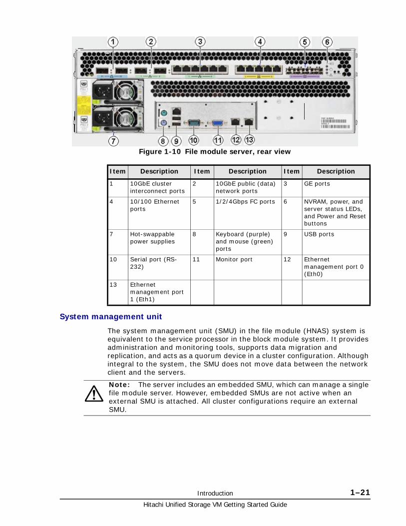
System management unit
The system management unit (SMU) in the file module (HNAS) system is equivalent to the service processor in the block module system. It provides administration and monitoring tools, supports data migration and replication, and acts as a quorum device in a cluster configuration. Although integral to the system, the SMU does not move data between the network client and the servers.
Figure 1-10 File module server, rear view
Item Description Item Description Item Description
1 10GbE cluster interconnect ports
2 10GbE public (data) network ports
3 GE ports
4 10/100 Ethernet ports
5 1/2/4Gbps FC ports 6 NVRAM, power, and server status LEDs, and Power and Reset buttons
7 Hot-swappable power supplies
8 Keyboard (purple) and mouse (green) ports
9 USB ports
10 Serial port (RS-232)
11 Monitor port 12 Ethernet management port 0 (Eth0)
13 Ethernet management port 1 (Eth1)
Note: The server includes an embedded SMU, which can manage a single file module server. However, embedded SMUs are not active when an external SMU is attached. All cluster configurations require an external SMU.

Hitachi Unified Storage VM Getting Started Guide
1–22 Introduction
Fibre channel (FC) switches
The HUS VM file module supports Fibre Channel switches that connect servers to storage subsystems. Contact Hitachi Data Systems Support Center for information about which Fibre Channel switches are supported.
External fast ethernet (10/100) or GigE switches
A standalone HUS VM file module can operate without an external Ethernet switch, as long as it uses an internal SMU and there are less than three RAID subsystems attached.A standalone file module server requires an external Ethernet switch if there are three or more RAID subsystems attached or if there are two RAID subsystems attached and an external SMU is used. All cluster configurations require an external Ethernet switch.
10 GbE (10 Gigabit Ethernet) switches (cluster configurations only)
The HUS VM file module server supports 10 GbE switches that connect multiple storage servers configured as a cluster. Contact your Hitachi Data Systems representative for information about the 10 GbE switches that have been qualified for use with the file module system, and to find out about the availability of those switches.
Currently, the only 10 GbE switch that has been qualified is the Brocade TurboIron 24X, a standalone 10Gbps Managed Layer 2 Ethernet switch with eight ports. It is available through Hitachi Data Systems. Hitachi Data Systems requires dual 10 GbE switches for redundancy. If one switch fails, the cluster nodes remain connected through the second switch.
Figure 1-11 System management server
Item Description Item Description Item Description
1 Power supply 2 Mouse port 3 Keyboard port
4 USB ports (2) 5 Serial connection 6 Video connection
7 Eth0 port (public network)
8 Eth1 port (private network)

2
Unified Storage VM task roadmap 2–1Hitachi Unified Storage VM Getting Started Guide
Unified Storage VM task roadmap
This chapter provides an ordered task list to plan and prepare the installation site, and to install and configure the system, with pointers to the Unified Storage VM user guides that provide the instructions for the tasks.
□ Required setup tasks
□ Optional setup tasks

Hitachi Unified Storage VM Getting Started Guide
2–2 Unified Storage VM task roadmap
Required setup tasksThe following tables show ordered lists of the tasks that must be completed to set up a Unified Storage VM storage system.
General task listThe following table provides a high-level list of installation and configuration tasks. The tables following it provide more detailed task lists. See the information following this table or the related user guides for detailed task lists and instructions.
Task Block Module File Module
1. Prepare the site 1. Site preparation tasks on page 2-3
Hitachi Unified Storage File Module System Installation Guide (technical support only)
2. Turn the storage system power on
2. Startup tasks on page 2-4 • Hitachi Unified Storage File Module Hardware Reference
• Hitachi Unified Storage File Module System Installation Guide (technical support only)
3. Log in to the system 3. Basic system admin tasks on page 2-4
Hitachi Unified Storage File Module Hardware Reference
4. Log in to the system Hitachi Unified Storage VM Block Module Hitachi Storage Navigator User Guide
Hitachi Unified Storage File Module Storage Systems User Administration Guide
5. Set up user accounts, enable software licenses
Hitachi Unified Storage VM Block Module Hitachi Storage Navigator User Guide
Hitachi Unified Storage File Module Storage Systems User Administration Guide
6. Provision and configure the system
4. Provisioning and configuration tasks on page 2-5
Hitachi Unified Storage File Module Storage Subsystem Administration Guide
7. Set up virtualization 5. Storage virtualization tasks on page 2-6
• Hitachi Unified Storage File Module File Services Administration Guide
• Hitachi Unified Storage File Module Storage Subsystem Administration Guide
8. Set up replication 6. Data replication and disaster recovery tasks on page 2-6
• Hitachi Unified Storage File Module Network Administration Guide
• Hitachi Unified Storage File Module Replication and Disaster Recovery Administration Guide
• Hitachi Unified Storage File Module Snapshot Administration Guide
Unified Storage VM task roadmap 2–3Hitachi Unified Storage VM Getting Started Guide
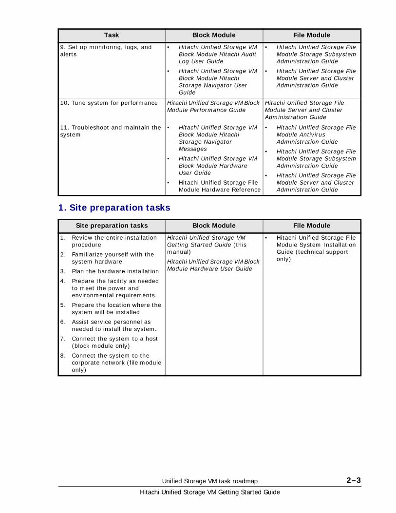
1. Site preparation tasks
9. Set up monitoring, logs, and alerts
• Hitachi Unified Storage VM Block Module Hitachi Audit Log User Guide
• Hitachi Unified Storage VM Block Module Hitachi Storage Navigator User Guide
• Hitachi Unified Storage File Module Storage Subsystem Administration Guide
• Hitachi Unified Storage File Module Server and Cluster Administration Guide
10. Tune system for performance Hitachi Unified Storage VM Block Module Performance Guide
Hitachi Unified Storage File Module Server and Cluster Administration Guide
11. Troubleshoot and maintain the system
• Hitachi Unified Storage VM Block Module Hitachi Storage Navigator Messages
• Hitachi Unified Storage VM Block Module Hardware User Guide
• Hitachi Unified Storage File Module Hardware Reference
• Hitachi Unified Storage File Module Antivirus Administration Guide
• Hitachi Unified Storage File Module Storage Subsystem Administration Guide
• Hitachi Unified Storage File Module Server and Cluster Administration Guide
Site preparation tasks Block Module File Module
1. Review the entire installation procedure
2. Familiarize yourself with the system hardware
3. Plan the hardware installation
4. Prepare the facility as needed to meet the power and environmental requirements.
5. Prepare the location where the system will be installed
6. Assist service personnel as needed to install the system.
7. Connect the system to a host (block module only)
8. Connect the system to the corporate network (file module only)
Hitachi Unified Storage VM Getting Started Guide (this manual)
Hitachi Unified Storage VM Block Module Hardware User Guide
• Hitachi Unified Storage File Module System Installation Guide (technical support only)
Task Block Module File Module

Hitachi Unified Storage VM Getting Started Guide
2–4 Unified Storage VM task roadmap
2. Startup tasks
3. Basic system admin tasks
Storage Management Task Block Module File Module
1. Verify that power to the rack is correct and turned on
2. Verify that all PDU breakers and switches are ON.
3. Turn on system power
4. Verify that the ready LED is ON.
Hitachi Unified Storage VM Block Module Hardware User Guide
Hitachi Unified Storage File Module Hardware Reference
Storage Management Task Block Module File Module
1. Log in
2. Change admin password
3. Set up user accounts
4. Enable license keys
Hitachi Unified Storage VM Block Module Hitachi Storage Navigator User Guide
• Hitachi Unified Storage File Module System Access Guide
• Hitachi Unified Storage File Module Storage System User Administration Guide
• Hitachi Unified Storage File Module Server and Cluster Administration Guide

Unified Storage VM task roadmap 2–5Hitachi Unified Storage VM Getting Started Guide
4. Provisioning and configuration tasks
Storage Management Task Block Module File Module
Block Module
Provision the Unified Storage VM system for use with open systems.
1. Verify that the system on which you are installing the software meets the minimum requirements for the software release.
2. Prepare the fibre-channel HBAs for the installation.
3. Verify recognition of the new devices.
4. Verify device files and the driver.
5. Create open-systems volumes
6. Partition disk devices, create file systems, and set device parameters.
7. Create mount directories, mount and verify the file systems, and set and verify auto-mount parameters.
8. Configure hosts and ports.
9. Define paths to volumes.
10. Assign access attribute to volumes.
11. Implement dynamic allocation of disk space on an as-needed basis.
• Hitachi Unified Storage VM Block Module Provisioning Guide
• Hitachi Unified Storage VM Hitachi System Operations Using Spreadsheets
• n/a
File Module
1. Perform basic system configuration
2. Create system drives
3. Create storage pools
4. Create file systems
5. Create mount points (CIFS shares or NFS exports)
• n/a • Hitachi Unified Storage File Module System Installation Guide (technical support only)
• Hitachi Unified Storage File Module Storage Subsystem Administration Guide
• Hitachi Unified Storage File Module File Services Administration Guide

Hitachi Unified Storage VM Getting Started Guide
2–6 Unified Storage VM task roadmap
5. Storage virtualization tasks
6. Data replication and disaster recovery tasks
Optional setup tasks The following tables list the optional setup tasks that you can use to customize your storage system.
Storage Management Task Block Module File Module
1. Connect external storage systems to the HUS VM storage system for storage virtualization.
2. Set up virtual volumes.
• Hitachi Unified Storage VM Block Module Hitachi Universal Volume Manager User Guide
• Hitachi Unified Storage VM Block Module Performance Guide
• Hitachi Unified Storage VM Hitachi System Operations Using Spreadsheets
• Hitachi Unified Storage File Module File Services Administration Guide
Storage Management Task Block Module File Module
Perform synchronous remote replication and disaster recovery.
Hitachi Unified Storage VM Block Module Hitachi TrueCopy® User Guide
• Hitachi Unified Storage File Module Replication and Disaster Recovery Administration Guide
• Hitachi Unified Storage File Module Snapshot Administration Guide
Perform asynchronous remote replication and disaster recovery.
Hitachi Unified Storage VM Block Module Hitachi Universal Replicator User Guide
• Hitachi Unified Storage File Module Replication and Disaster Recovery Administration Guide
• Hitachi Unified Storage File Module Snapshot Administration Guide
Perform local replication. Hitachi Unified Storage VM Block Module Hitachi ShadowImage® User Guide
• Hitachi Unified Storage File Module Replication and Disaster Recovery Administration Guide
Install Command Control Interface (CCI).
Hitachi Command Control Interface Installation and Configuration Guide
n/a
Use CCI commands to perform data replication.
Hitachi Command Control Interface User and Reference Guide
n/a

Unified Storage VM task roadmap 2–7Hitachi Unified Storage VM Getting Started Guide
1. Provisioning and configuration
2. Performance monitoring and tuning tasks
3. Troubleshooting and other tasks
Storage Management Task Block Module File Module
Use SNMP-based reporting on status and alerts for the storage system
Hitachi Unified Storage VM Block Module Hitachi SNMP Agent User Guide
Hitachi Unified Storage File Module Server and Cluster Administration Guide
(Security) Delete data from volumes to prevent it from being restored
Hitachi Unified Storage VM Block Module Hitachi Volume Shredder User Guide
n/a
Storage Management Task Block Module File Module
Monitor performance statistics of disk drives, volumes, and other storage components
Hitachi Unified Storage VM Block Module Performance Guide
• Hitachi Unified Storage File Module Server and Cluster Administration Guide
Improve data access speed using cache
n/a
Create and managing virtual cache partitions
n/a
Storage Management Task Block Module File Module
Review information about GUI messages
Hitachi Unified Storage VM Block Module Hitachi Storage Navigator Messages
n/a
Review the log of operations to investigate causes of errors and avoid potential errors
Hitachi Unified Storage VM Block Module Hitachi Audit Log User Guide
Hitachi NAS Platform Troubleshooting Guide (Technical Support only)
Review syntax of CCI commands Hitachi Command Control Interface Command Reference
Hitachi NAS Platform Command Line Reference (accessed through HNAS Web Manager)

Hitachi Unified Storage VM Getting Started Guide
2–8 Unified Storage VM task roadmap

3
Site preparation 3–1Hitachi Unified Storage VM Getting Started Guide
Site preparation
This chapter provides brief site and system requirements and information that is needed to plan a Hitachi Unified Storage VM storage system installation and prepare the site where the system will be installed, so that the equipment installation is efficient and trouble-free. See Chapter 5, Site Preparation, in the Hitachi Unified Storage VM Block Module Hardware User Guide for details and specifications needed to prepare a site for Hitachi Unified Storage VM storage system installation.
.
□ Responsibilities
□ Site Preparation checklist

Hitachi Unified Storage VM Getting Started Guide
3–2 Site preparation
ResponsibilitiesThe responsibilities for site planning and preparation are shared by the system users and Hitachi Data Systems support. The required installation planning tasks must be scheduled and completed to ensure successful and efficient installation of the Unified Storage VM storage system.
User responsibilitiesYou are responsible for performing the following tasks to prepare your site for installation of the HUS VM storage system.
• Understand the applicable safety requirements associated with installing a HUS VM storage system.
• Understand the installation requirements for the HUS VM storage system. You can use the information in this manual to determine the specific requirements for your installation. As needed, review the Hitachi Unified Storage VM Block Module Hardware User Guide to familiarize yourself with the components, features, and functions of the HUS VM storage system.
• Verify that the installation site meets all installation requirements. A checklist is included in this section to help you with this task.
• Provide electrical hardware, including cables, connectors and receptacles that are required to connect the HUS VM storage system to site power.
• As needed, work with Hitachi Data Systems support to create an installation plan. Allow enough time to complete any changes to the plan, so your site is ready when the equipment arrives.
Hitachi Data Systems responsibilitiesHitachi Data Systems support is responsible for completing the following tasks:
• Assist you as needed during the installation planning process for your specific site and operational configuration
• Coordinate Hitachi Data Systems resources to ensure a successful installation and configuration of the Unified Storage VM storage system.
Site Preparation checklistThe following checklist can help you ensure that your site meets all requirements to install a Unified Storage VM storage system. You can make copies of this checklist for each installation you perform and check each step after it has been performed. Completing this checklist can help ensure smooth and efficient installation of a HUS VM storage system.
Definition of terms
Note: The HUS VM storage system must be installed by trained Hitachi Data Systems personnel or trained authorized service providers. The HUS VM storage system is not a customer-installable product.

Site preparation 3–3Hitachi Unified Storage VM Getting Started Guide
Equipment: The hardware delivered to the customer site that includes the HUS VM storage system components. The system may be installed in a Hitachi rack when delivered or assembled on site. The delivered equipment may include only the system components if the customer supplies a standard 19-inch rack. Rack specifications are located in the Hitachi Unified Storage VM Block Module Hardware User Guide..
Location: The specific location in the data center (area or “footprint” on the floor) where the HUS VM storage system will be installed.
User Information
Company
Address
Contact
Phone
Mobile
Contact
Phone
Mobile
Hitachi Data Systems Information
Contact
Phone
Mobile
Contact
Phone
Mobile
Notes .
Preinstallation Checklist Yes No
Safety Requirements
See Data center requirements in Chapter 5 in the Hitachi Unified Storage VM Block Module Hardware User Guide.
Does the data center provide appropriate fire protection for computer equipment similar to HUS VM storage systems?
Is the data center free of hazards such as cables that obstruct access to the equipment?
Delivery Requirements
See Chapter 5 in the Hitachi Unified Storage VM Block Module Hardware User Guide.
Is the receiving area adequate for equipment delivery, unloading and unpacking? .

Hitachi Unified Storage VM Getting Started Guide
3–4 Site preparation
Are all doors, hallways, elevators, and ramps wide enough and high enough to allow the equipment to be moved from the receiving area to the installation area?
Can the floors, elevators, and ramps support the weight of the equipment? See .
Storage Requirements
See Chapter 5 in the Hitachi Unified Storage VM Block Module Hardware User Guide.
If the equipment will be stored after delivery and prior to installation, does the storage location meet the environmental requirements for storing a HUS VM storage system?
Facilities Requirements
See Chapter 5 in the Hitachi Unified Storage VM Block Module Hardware User Guide.
Does the data center have a raised floor?
Does the location meet the requirements for service clearance and cable routing (for example, floor cutouts)? See
Does the installation site meet the floor load rating requirements?
Power Requirements
See Chapter 5 in the Hitachi Unified Storage VM Block Module Hardware User Guide.
Does the data center meet the AC input power requirements? .
Does the data center meet the circuit breaker and plug requirements? See .
Is the customer-supplied hardware such as connectors, receptacles, and cables ready for the installation?
Environmental Requirements
See Chapter 5 in the Hitachi Unified Storage VM Block Module Hardware User Guide.
Does the data center meet the following operational environmental requirements for a HUS VM storage system? .
temperature
humidity
altitude
air flow
Does the data center provide adequate protection for a HUS VM storage system from the following?
electrostatic discharge
electrical/radio frequency interference
. dust, pollution, and particulate contamination
Does the data center provide adequate acoustic insulation to operate the Unified Storage VM storage system?
Preinstallation Checklist Yes No

Site preparation 3–5Hitachi Unified Storage VM Getting Started Guide
Operational Requirements
See Chapter 5 in the Hitachi Unified Storage VM Block Module Hardware User Guide.
Does the data center provide a LAN for Storage Navigator?
Does the location meet the cable length requirements for the front-end directors?
Does the location meet the requirements for attaching external storage?
Preinstallation Checklist Yes No

Hitachi Unified Storage VM Getting Started Guide
3–6 Site preparation

A
Hitachi Unified Storage VM user guides A–1Hitachi Unified Storage VM Getting Started Guide
Hitachi Unified Storage VM user guides
This section provides a list of all Hitachi Unified Storage VM user documentation, by topic. The Hitachi Unified Storage VM system includes both the block module and the file module systems.
□ Unified Storage VM user guides by topic
Hitachi Unified Storage VM Getting Started Guide
A–2 Hitachi Unified Storage VM user guides
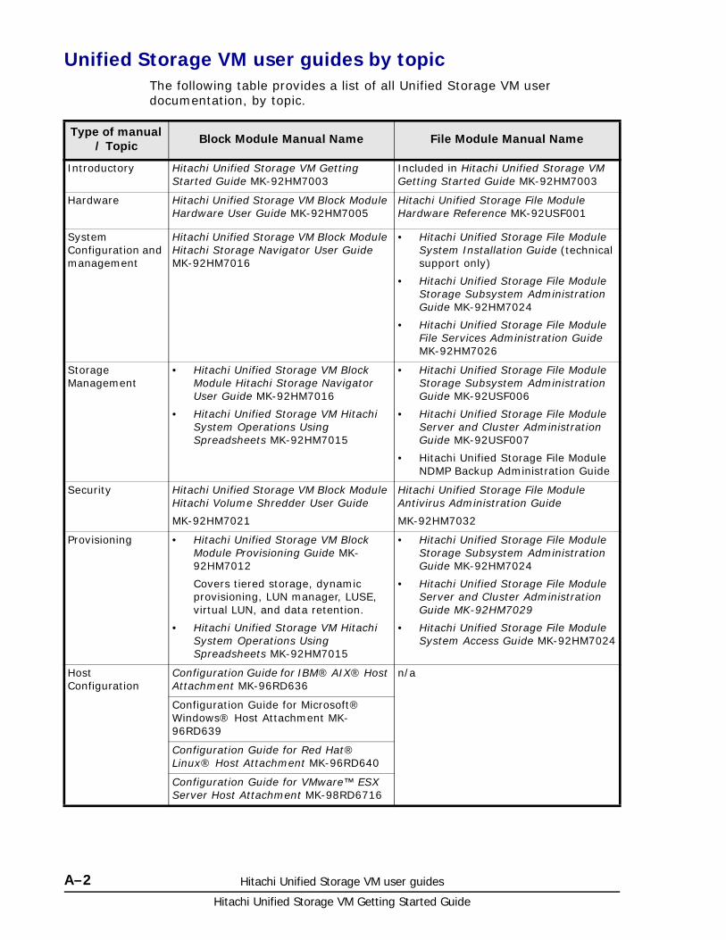
Unified Storage VM user guides by topicThe following table provides a list of all Unified Storage VM user documentation, by topic.
Type of manual / Topic Block Module Manual Name File Module Manual Name
Introductory Hitachi Unified Storage VM Getting Started Guide MK-92HM7003
Included in Hitachi Unified Storage VM Getting Started Guide MK-92HM7003
Hardware Hitachi Unified Storage VM Block Module Hardware User Guide MK-92HM7005
Hitachi Unified Storage File Module Hardware Reference MK-92USF001
System Configuration and management
Hitachi Unified Storage VM Block Module Hitachi Storage Navigator User Guide MK-92HM7016
• Hitachi Unified Storage File Module System Installation Guide (technical support only)
• Hitachi Unified Storage File Module Storage Subsystem Administration Guide MK-92HM7024
• Hitachi Unified Storage File Module File Services Administration Guide MK-92HM7026
Storage Management
• Hitachi Unified Storage VM Block Module Hitachi Storage Navigator User Guide MK-92HM7016
• Hitachi Unified Storage VM Hitachi System Operations Using Spreadsheets MK-92HM7015
• Hitachi Unified Storage File Module Storage Subsystem Administration Guide MK-92USF006
• Hitachi Unified Storage File Module Server and Cluster Administration Guide MK-92USF007
• Hitachi Unified Storage File Module NDMP Backup Administration Guide
Security Hitachi Unified Storage VM Block Module Hitachi Volume Shredder User Guide
MK-92HM7021
Hitachi Unified Storage File Module Antivirus Administration Guide
MK-92HM7032
Provisioning • Hitachi Unified Storage VM Block Module Provisioning Guide MK-92HM7012
Covers tiered storage, dynamic provisioning, LUN manager, LUSE, virtual LUN, and data retention.
• Hitachi Unified Storage VM Hitachi System Operations Using Spreadsheets MK-92HM7015
• Hitachi Unified Storage File Module Storage Subsystem Administration Guide MK-92HM7024
• Hitachi Unified Storage File Module Server and Cluster Administration Guide MK-92HM7029
• Hitachi Unified Storage File Module System Access Guide MK-92HM7024
Host Configuration
Configuration Guide for IBM® AIX® Host Attachment MK-96RD636
n/a
Configuration Guide for Microsoft® Windows® Host Attachment MK-96RD639
Configuration Guide for Red Hat® Linux® Host Attachment MK-96RD640
Configuration Guide for VMware™ ESX Server Host Attachment MK-98RD6716

Hitachi Unified Storage VM user guides A–3Hitachi Unified Storage VM Getting Started Guide
Virtualization Hitachi Unified Storage VM Block Module Hitachi Universal Volume Manager User Guide MK-92HM7020
Hitachi Unified Storage File Module File Services Administration Guide MK-92HM7026
Replication • Hitachi Unified Storage VM Block Module Hitachi ShadowImage® User Guide MK-92HM7013
• Hitachi Unified Storage VM Block Module Hitachi TrueCopy® User Guide MK-92HM7018
• Hitachi Unified Storage VM Block Module Hitachi Universal Replicator User Guide MK-92HM7019
• Hitachi Unified Storage VM Block Module Thin Image User Guide MK-92HM7010
• Hitachi Unified Storage File Module Network Administration Guide MK-92USF003
• Hitachi Unified Storage File Module Replication and Disaster Recovery Administration Guide MK-92USF009
• Hitachi Unified Storage File Module Snapshot Administration Guide MK-92USF008
Command line entry
• Hitachi Command Control Interface Command Reference MK-90RD7009
• Hitachi Command Control Interface User and Reference Guide
MK-90RD7010
• Hitachi Command Control Interface Installation and Configuration Guide
MK-90RD7011
Hitachi NAS Platform Command Line Reference (accessed through HNAS Web Manager)
Performance Hitachi Unified Storage VM Block Module Performance Guide MK-92HM7011
• Hitachi Unified Storage File Module Server and Cluster Administration Guide MK-92HM7029
• Hitachi Unified Storage File Module Storage Subsystem Administration Guide MK-92HM7029
System Maintenance
Hitachi Unified Storage VM Block Module Hitachi SNMP Agent User Guide
MK-92HM7014
Hitachi Unified Storage File Module Storage Subsystem Administration Guide MK-92HM7029
Hitachi Unified Storage VM Block Module Hitachi Audit Log User Guide
MK-92HM7009
Hitachi Unified Storage File Module Server and Cluster Administration Guide MK-92HM7029
Backup Operations
n/a Hitachi Unified Storage File Module NDMP Backup Administration Guide
MK-92HM7034
Troubleshooting • Hitachi Unified Storage VM Block Module Hitachi Storage Navigator User Guide MK-92HM7016
• Hitachi Unified Storage VM Block Module Hitachi Storage Navigator Messages MK-92HM7017
Hitachi NAS Platform Troubleshooting Guide (Technical Support only)
Type of manual / Topic Block Module Manual Name File Module Manual Name

Hitachi Unified Storage VM Getting Started Guide
A–4 Hitachi Unified Storage VM user guides

CA KD E F G H I J L M N O P Q R S T U V W X Y# B ZA B C D F H J K L M P R S V
Glossary–1Hitachi Unified Storage VM Getting Started Guide
Glossary
This glossary defines the special terms used in this document.
A
array
See disk array..
B
back-end I/O module
The hardware component that controls the transfer of data between the drives and cache. A back-end I/O module feature consists of a pair of boards. A back-end I/O module is also referred to as a disk adapter (DKA).
C
CHA
See channel adapter.
controller chassis
The hardware assembly that contains the logic and processing components of the Unified Storage VM storage system, including the front-end directors, virtual storage directors, cache memory, switches, and back-end directors. The Unified Storage VM storage system can be configured with one or two control chassis.

CA KD E F G H I J L M N O P Q R S T U V W X Y# B ZA B C D F H J K L M P R S V
Hitachi Unified Storage VM Getting Started Guide
Glossary–2
D
disk array
Disk array, or just array, is a complete storage system, including the control and logic devices, drives, connecting cables, and racks.
drive box
The hardware component of the Unified Storage VM that houses disk drives and/or flash drives.
dynamic provisioning
An approach to managing storage. Instead of “reserving” a fixed amount of storage, it removes capacity from the available pool when data is actually written to disk. Also called thin provisioning.
F
flash drive
A data drive that uses a solid-state memory device instead of a rotating hard disk drive to store information.
free capacity
The amount of storage space (in bytes) that is available for use by the host system(s).
H
host I/O module
The hardware component that processes channel commands from hosts and manages host access to cache. A host I/O module is also referred to as a channel adapter (CHA).
J
JRE
Java Runtime Environment
JVM
Java Virtual Machine
K
kVA
kilovolt-ampere

CA KD E F G H I J L M N O P Q R S T U V W X Y# B ZA B C D F H J K L M P R S V
Glossary–3Hitachi Unified Storage VM Getting Started Guide
L
LDEV
logical device
license key
A specific set of characters that unlocks an application and allows it to be used.
logical device (LDEV)
An individual logical data volume (on multiple drives in a RAID configuration) in the storage system. An LDEV may or may not contain any data and may or may not be defined to any hosts. Each LDEV has a unique identifier or “address” within the storage system composed of the logical disk controller (LDKC) number, control unit (CU) number, and LDEV number. The LDEV IDs within a storage system do not change.An LDEV formatted for use by mainframe hosts is called a logical volume image (LVI). An LDEV formatted for use by open-system hosts is called a logical unit (LU).
logical volume
See volume.
LUN
logical unit number. Sometimes used in place of LU, logical unit.
LUSE
LUN Size Expansion
M
mirror
In Universal Replicator, each pair relationship in and between journal groups is called a “mirror”. Each pair is assigned a mirror ID when it is created. The mirror ID identifies individual pair relationships between journal groups.
modify mode
The mode of operation of Storage Navigator that allows changes to the storage system configuration. See also view mode.

CA KD E F G H I J L M N O P Q R S T U V W X Y# B ZA B C D F H J K L M P R S V
Hitachi Unified Storage VM Getting Started Guide
Glossary–4
P
pair
Two logical volumes in a replication relationship in which one volume contains original data to be copied and the other volume contains the copy of the original data. The copy operations can be synchronous or asynchronous, and the pair volumes can be located in the same storage system (in-system replication) or in different storage systems (remote replication).
pair status
Indicates the condition of a copy pair. A pair must have a specific status for specific operations. When an operation completes, the status of the pair changes to the new status.
PDB
power distribution box
PDP
power distribution panel
PDU
power distribution unit
pool
A set of volumes that are reserved for storing Copy-on-Write Snapshot data or Dynamic Provisioning write data.
R
RAID
redundant array of independent disks. A disk array in which part of the physical storage space is used to store user data and parity information, and another part is used to store a duplicate set of user data and parity information. This redundant configuration prevents data loss in case a disk drive within the RAID configuration fails, and enables regeneration of user data in the event that one of the array's member disks or the access path to it fails.
RAID group
A set of RAID disks that have the same capacity and are treated as one group for data storage and recovery. A RAID group contains both user data and parity information. This allows user data to be accessed in the event that one or more of the drives within the RAID group are not available. The RAID level of a RAID group determines the number of data drives and parity drives and how the data is “striped” across the

CA KD E F G H I J L M N O P Q R S T U V W X Y# B ZA B C D F H J K L M P R S V
Glossary–5Hitachi Unified Storage VM Getting Started Guide
drives. For RAID1, user data is duplicated within the RAID group, so there is no parity data for RAID1 RAID groups.
A RAID group can also be called an array group or a parity group.
RAID level
The type of RAID implementation. RAID levels include RAID0, RAID1, RAID2, RAID3, RAID4, RAID5 and RAID6.
S
SAS
serial-attached SCSI
SATA
serial Advanced Technology Attachment
service information message (SIM)
SIMs are generated by a storage system when it detects an error or service requirement. SIMs are reported to hosts and displayed on Storage Navigator.
service processor (SVP)
The computer in a VSP storage system that hosts the Storage Navigator software and is used to configure and maintain the storage system.
SIM
service information message
SOM
system option mode
SSD
solid state drive. See flash drive.
SVP
See service processor (SVP).
system disk
The volume from which an open-systems host boots.
system option mode (SOM)
Additional operational parameters for the RAID storage systems that enable the storage system to be tailored to unique customer operating requirements. SOMs are set on the service processor.

CA KD E F G H I J L M N O P Q R S T U V W X Y# B ZA B C D F H J K L M P R S V
Hitachi Unified Storage VM Getting Started Guide
Glossary–6
V
volume
A logical device (LDEV), or a set of concatenated LDEVs in the case of LUSE, that has been defined to one or more hosts as a single data storage unit. A mainframe volume is called a logical volume image (LVI), and an open-systems volume is called a logical unit. (LU).

Index–1Hitachi Unified Storage VM Getting Started Guide
Index
Bbasic configuration;configuration
basic 1–7, 1–19
Ccapacity
cache 1–4disk drive 1–4
checklist 3–2configuration
maximum 1–4minimum 1–4, 1–16
controller chassis 1–8, 1–19controller, components 1–9, 1–19
Ffeatures
hardware 1–2software 1–13
Rrequirements
delivery 3–3facilities 3–4installation 3–1, 3–2operational 3–5power 3–4safety 3–2, 3–3storage 3–4
responsibilitiessupport team 3–2
respopnsibilitiesuser 3–2
Sspecifications
drive 1–4, 1–12general 1–10

Hitachi Unified Storage VM Getting Started Guide
Index–2

Hitachi Unified Storage VM Getting Started Guide

MK-92HM7003-01
Hitachi Data Systems
Corporate Headquarters72845 Lafayette StreetSanta Clara, California 95050-2639U.S.A.www.hds.com
Regional Contact Information
Americas+1 408 970 [email protected]
Europe, Middle East, and Africa+44 (0)1753 [email protected]
Asia Pacific+852 3189 [email protected]