hvac design overview of variable air volume systems · hvac design overview of variable air volume...
TRANSCRIPT

PDHonline Course M252 (4 PDH)
HVAC Design Overview ofVariable Air Volume Systems
2012
Instructor: A. Bhatia, B.E.
PDH Online | PDH Center5272 Meadow Estates Drive
Fairfax, VA 22030-6658Phone & Fax: 703-988-0088
www.PDHonline.orgwww.PDHcenter.com
An Approved Continuing Education Provider
www.PDHcenter.com PDH Course M252 www.PDHonline.org
© 2007 A. Bhatia Page 2 of 43
HVAC Design Overview of Variable Air Volume Systems A. Bhatia, B.E.
VARIABLE AIR VOLUME SYSTEMS
In central air conditioning systems there are two basic methods for delivering air to the
conditioned space 1) the constant air volume (CAV) systems and 2) the variable air volume
(VAV) systems. As the name implies, constant volume systems deliver a constant air
volume to the conditioned space irrespective of the load with the air conditioner cycling on
and off as the load varies. The fan may or may not continue to run during the off cycle. VAV
systems, on the other hand, are designed to simultaneously meet a variety of cooling and
heating loads in a relatively efficient manner. The system achieves this by varying the
distribution of air depending on the cooling or heating loads of each area. The air flow
variation allows for adjusting the temperature in a single zone without changing the
temperature of air in the whole system, minimizing any instances of overcooling or
overheating. This flexibility has made this one of the most popular HVAC systems for large
buildings with varying conditioning needs such as office buildings, schools, or apartments.
How a VAV system works?
What distinguishes a variable air volume system from other types of air delivery systems is
the use of a variable air volume box in the ductwork. The most basic VAV box consists of an
enclosure with a small air valve (damper) that regulates the air flow in response to the
room's thermostat.
In a VAV system, an air handling unit (AHU) cools or heats air to accommodate the zone
with the most extreme requirements, supplying the air through ducts to various zones. At
the individual zone or space, the amount of air to be provided is regulated by air valves
within a VAV box or terminal. As the load decreases in a particular zone, the VAV air valve
throttles the airflow matching the space requirements. Also when there is a sudden increase
in load, the temperature sensor located in the zone will detect a rise in temperature and
request the VAV box to open the air valve and increase the amount of cool air flow.
When a VAV box air valve closes, the static pressure in the adjacent runout and trunk duct
will increase, resulting in increased airflow through the adjacent ductwork. This change in
airflow will affect the space temperature in the new area supplied by that ductwork because
a higher volume of air (usually cooled) is now flowing into the area. The space thermostat in
this area will eventually sense this change in temperature, and re-position its air valve for

www.PDHcenter.com PDH Course M252 www.PDHonline.org
© 2007 A. Bhatia Page 3 of 43
reduced flow. This reduced flow will cause a further increase in static pressure in adjacent
ductwork and increase flow even further to other air terminals. This effect continues
unabated and will eventually cause unbalance in the entire air distribution ductwork.
It is apparent that space thermostats alone can never stabilize a space temperature.
Therefore, an additional static pressure control is added in the system, which maintains the
duct static pressure within a set range. A static pressure sensor senses the increase in duct
static pressure and provides signal to fan controller to reduce the speed. A reduction in fan
speed will reduce the airflow in direct proportion to the speed. At this point, it is important
to revisit “fan laws”:
1. Volume varies directly with speed ratio
CFM1 /CFM2 = RPM1 /RPM2
2. Pressure varies with square of speed ratio
SP1 /SP2 = (RPM1 /RPM2)2
3. Power varies with cube of speed ratio
W1 /W2 = (RPM1 /RPM2)3
Example
A fan installed in a fixed system is operating at:
• CFM = 10,000
• SP = 1.50"
• BHP = 5.00
• RPM = 1,000
How will the SP, BHP and RPM vary, if the fan is required to move 25% less air (7500 CFM)
through this system?
By rearranging the CFM fan law:
RPM2 = [CFM2 /CFM1] x RPM1
RPM2 = [7500/10000] x 1000 = 750 RPM
The corresponding static pressure is:
SP2 = [RPM2 /RPM1] 2 x SP1
SP2 = [750 /1000] 2 x 1.5 = 0.843”
www.PDHcenter.com PDH Course M252 www.PDHonline.org
© 2007 A. Bhatia Page 4 of 43
The resulting BHP is:
BHP2 = [RPM2 /RPM1] 3 x BHP1
BHP2 = [750 /1000] 3 x 5 = 2.11
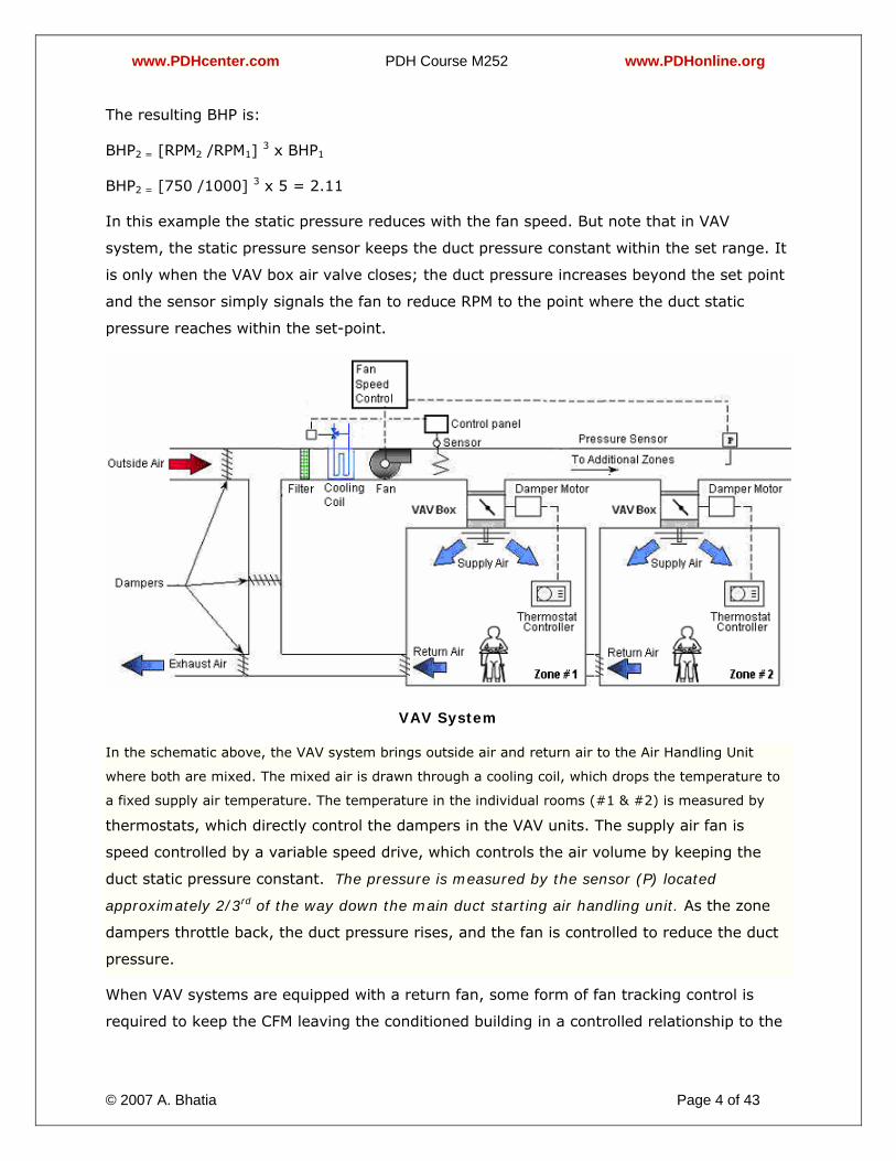
In this example the static pressure reduces with the fan speed. But note that in VAV
system, the static pressure sensor keeps the duct pressure constant within the set range. It
is only when the VAV box air valve closes; the duct pressure increases beyond the set point
and the sensor simply signals the fan to reduce RPM to the point where the duct static
pressure reaches within the set-point.
VAV System
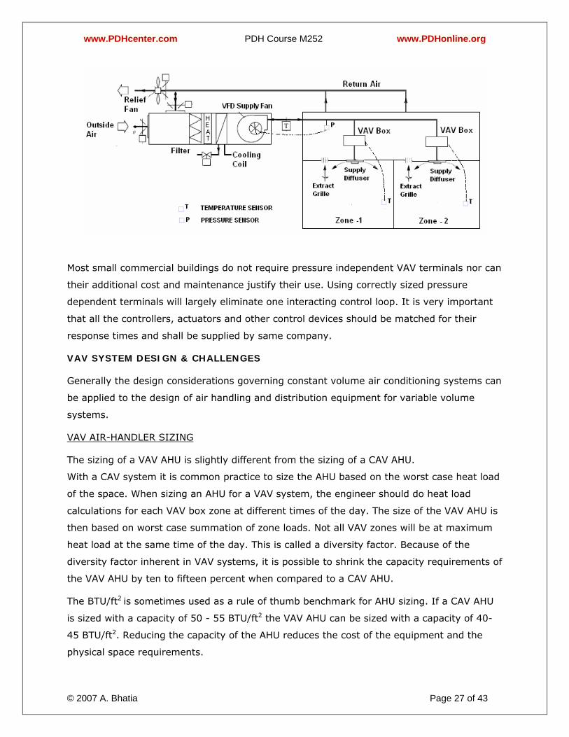
In the schematic above, the VAV system brings outside air and return air to the Air Handling Unit
where both are mixed. The mixed air is drawn through a cooling coil, which drops the temperature to
a fixed supply air temperature. The temperature in the individual rooms (#1 & #2) is measured by
thermostats, which directly control the dampers in the VAV units. The supply air fan is
speed controlled by a variable speed drive, which controls the air volume by keeping the
duct static pressure constant. The pressure is measured by the sensor (P) located
approximately 2/3rd of the way down the main duct starting air handling unit. As the zone
dampers throttle back, the duct pressure rises, and the fan is controlled to reduce the duct
pressure.
When VAV systems are equipped with a return fan, some form of fan tracking control is
required to keep the CFM leaving the conditioned building in a controlled relationship to the
www.PDHcenter.com PDH Course M252 www.PDHonline.org
© 2007 A. Bhatia Page 5 of 43
CFM being supplied to the building. There are several ways of doing this. One method is to
maintain a constant CFM differential between supply and return air flows. Another method is
to vary the return fan CFM to maintain a pre-determined space pressure. You may
encounter either method in the field. We will study this, later in this course.
VAV Systems – Benefits
Here are a few of the advantages of VAV systems:
1. Efficiency –
VAV systems are low on energy consumption. During lean periods, the air handling unit
fan can run at a slower speed (through the use of a variable speed drive) and the
amount heating and cooling mediums running through the coil can be reduced (through
2-way modulating valves or solenoid control valves). A VAV system allows the air
handling unit, chillers, and boilers to run a part load majority of time.
2. Individual Temperature Control –
VAV system provides optimum control of temperature especially in the areas with wide
load variations. Since each VAV box is linked to a thermostat, the ability to control
temperature in a space is independent of other spaces. Rooms with similar loading
patterns are often placed on the same VAV box, and through the use of a VAV system,
areas with very different loading patterns can be placed on the same air handling unit.
3. Humidity Control –
Humidity refers to moisture content in the air. It must be controlled in conjunction with
air temperature to provide a comfortable environment. VAV systems do an excellent job
of controlling building humidity since the air handler delivers constant-temperature, low-
dew-point air at all load conditions.
4. Cost –
Variable-air-volume (VAV) systems are sized for a diversified "block" load (peak
instantaneous demand) rather than a sum of zone "peak" loads. As a result the
equipment sizes (air handling units/refrigeration plant/ducts etc) are lowered thus
reducing the first initial cost.
5. Flexibility –
A VAV system is capable of serving multiple zones with varying load demands; this
allows a single air-handling unit to handle varying loads in an economical way.
www.PDHcenter.com PDH Course M252 www.PDHonline.org
© 2007 A. Bhatia Page 6 of 43
VAV systems are popular because they can easily accommodate added control zones.
VAV Systems are virtually self balancing since boxes are set for maximum and minimum
CFM. This feature almost completely eliminates costly and time consuming air quantity
setting procedures.
DISADVANTAGES
1. Each zone requires a terminal unit. This may cause spacing problems in smaller zones.
2. Terminal units must be in an easily accessible location for its particular zone, which may
complicate the system design.
3. Terminal units will require a power source to operate, resulting in extra electrical wiring.
4. Terminal units will require periodic maintenance in addition to usual attention paid to the
central unit.
5. VAV systems may require a secondary mechanical system to meet peak demands. Also,
a secondary system may be necessary to provide heating to zones when the majority of
the building requires cooling, or vice versa.
6. Circulation may become a problem when zone needs are met using minimal air flow.
DESIGN CHALLENGES
1. Inadequate ventilation - Providing proper ventilation with a simple VAV system
presents a challenge. ASHRAE Standard 62-1989, "Ventilation for Acceptable Indoor Air
Quality," mandates minimum outdoor air requirements of 20 CFM/person for ventilation.
Since with VAV systems, the amount of air delivered varies with load, restricting the air
flow can lead to inadequate outside air flow. The result is stuffiness and discomfort.
2. Poor Air Distribution - As a VAV system reaches its design set-point, the volume of air
delivered to a room is decreased. This affects the air distribution. A standard diffuser
may work well for constant volume applications, but not so well at part load air
velocities. When airflow is reduced, the distribution pattern is changed and can cause
stratification or drafts to occur.
3. Control problems - (1) How to sense small changes in static pressure, (2) How to
balance return air systems with variations in supply air, and (3) How to maintain a
constant flow of outside air with variations in supply and return airflows.
4. Space Requirements - The installation of a VAV box requires considerable space, both
in the vertical and horizontal directions. As a rule of thumb, the linear duct length before
www.PDHcenter.com PDH Course M252 www.PDHonline.org
© 2007 A. Bhatia Page 7 of 43
a VAV box should be three times the diameter of the inlet. This length is required for the
air profile in the duct to even out before entering the box. In the vertical direction, the
VAV box can require up to 18", which can be a problem if above ceiling heights are
relatively small.
5. VAV Box Location - Since VAV boxes must be located in the branch ductwork, they are
often placed above the ceiling. In situations where an acoustical ceiling is used, there is
easy access to the box. However, in situations where a plaster ceiling is present, an
access panel must be provided to allow access to the box.
It is important to note that the shortcomings of the applied VAV technology are not intrinsic
and these shall have limited impact if the design, installation and operation of the system
are properly addressed.
GENERAL APPLICATIONS
Variable air volume systems are very effective in medium to large scale buildings that
contain many smaller HVAC zones such as office buildings, schools, apartment buildings, or
hospitals. These applications require a mechanical system capable of handling large air
volumes while paying attention to the specific needs of each separated area.
Inappropriate Uses for a VAV System
Not acceptable for some critical areas such as hospitals because, at low load conditions, less
air is discharged from supply outlets. This may not meet strict ventilation, humidity control
and pressure regulation requirements to prevent infiltration of outside air in a clean
environment.
Laboratories/Hospitals and Clean room applications- Traditional VAV systems would not be a
good choice to use in a situation where pressurizing spaces is critical. For instance, a
hospital hallway serving isolation rooms must be positively pressured so that contagious
germs do not seep out of the isolation room. Since a traditional VAV system cannot assure a
constant volume of delivered air, it works poorly in positively pressured situations.
VAV systems may not be as desirable for smaller scale structures or structures that require
uniform heating or cooling in a large area, because the added control mechanisms would
add to expenses while not adding any desired benefits. Structures such as single family
homes or warehouses may find an alternative HVAC system to be much more economical.
TYPES OF VAV SYSTEMS
There are many different types of VAV units:
www.PDHcenter.com PDH Course M252 www.PDHonline.org
© 2007 A. Bhatia Page 8 of 43
1. Single Duct
2. Dual Duct
3. Reheat
4. Fan Powered
5. Series Fan
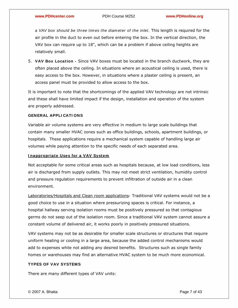
Single Duct VAV system
A single duct VAV (or cooling only VAV) is one of the most basic air terminal unit consisting
of a damper, actuator, flow sensor and selected controls. It is simply an enclosure with
single inlet and single outlet with an air valve in between.
Common Applications - It is used only in spaces where the variation in load is relatively
small. It is most often used in an interior zone of the building for cooling only. Generally,
these boxes should be used only where minimum ventilation is not a concern and,
therefore, can be set at zero.
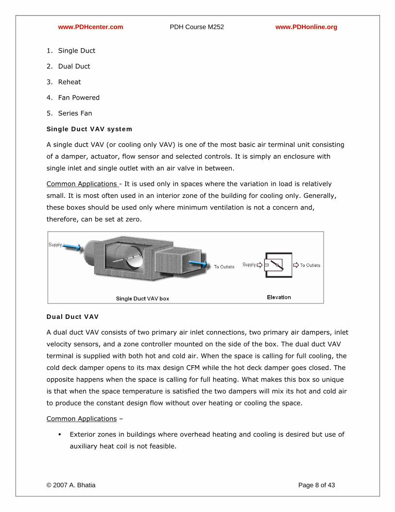
Dual Duct VAV
A dual duct VAV consists of two primary air inlet connections, two primary air dampers, inlet
velocity sensors, and a zone controller mounted on the side of the box. The dual duct VAV
terminal is supplied with both hot and cold air. When the space is calling for full cooling, the
cold deck damper opens to its max design CFM while the hot deck damper goes closed. The
opposite happens when the space is calling for full heating. What makes this box so unique
is that when the space temperature is satisfied the two dampers will mix its hot and cold air
to produce the constant design flow without over heating or cooling the space.
Common Applications –
Exterior zones in buildings where overhead heating and cooling is desired but use of
auxiliary heat coil is not feasible.
www.PDHcenter.com PDH Course M252 www.PDHonline.org
© 2007 A. Bhatia Page 9 of 43
Also where zero to low minimum flow is acceptable during changeover.
The following is a list of pros and con's for this type box:
• Keeps a constant airflow thru out the space.
• Will not allow air to get stagnant or stale.
• Allows more airflow to be filtered through main air handling unit.
• Brings in a more constant amount of fresh air (outside air).
• The Air Handling Unit will need to produce hot and cold air all year.
• A boiler and chiller will have to be run all year.
Two main ducts from the Air Handler will have to be run through out the building to supply
both hot and cold air, needing more above ceiling space.
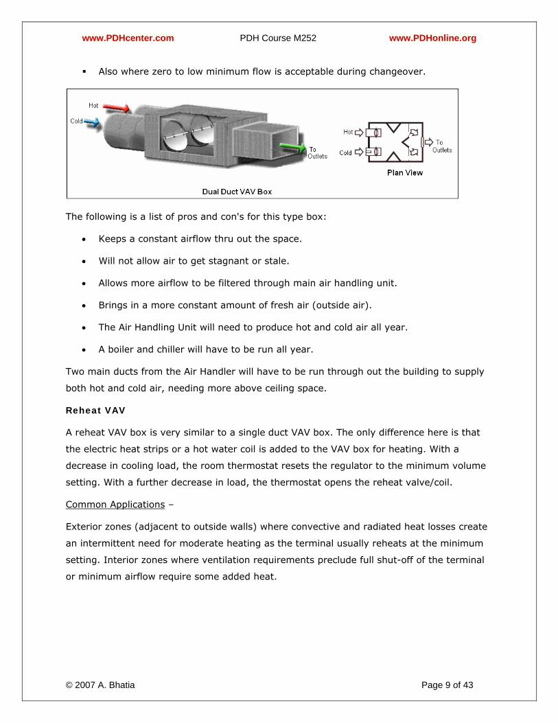
Reheat VAV
A reheat VAV box is very similar to a single duct VAV box. The only difference here is that
the electric heat strips or a hot water coil is added to the VAV box for heating. With a
decrease in cooling load, the room thermostat resets the regulator to the minimum volume
setting. With a further decrease in load, the thermostat opens the reheat valve/coil.
Common Applications –
Exterior zones (adjacent to outside walls) where convective and radiated heat losses create
an intermittent need for moderate heating as the terminal usually reheats at the minimum
setting. Interior zones where ventilation requirements preclude full shut-off of the terminal
or minimum airflow require some added heat.
www.PDHcenter.com PDH Course M252 www.PDHonline.org
© 2007 A. Bhatia Page 10 of 43
The following is a list of pro's and con's for this type of box.
• Has the ability to give the space cooling or heating without effecting temperatures in
other areas.
• Gives the space a larger percentage of fresh air (outside air).
• Airflow is better filtered because all of the airflow is being supplied by the main air
handler.
• All airflow entering the space is being dehumidified by the main air handler.
• Airflow that has been cooled to 55°F then heated back up is very inefficient and
expensive to run.
• Boilers and hot water pumps would have to run all year round when using hot water
reheat.
Bypass VAV Box
A bypass VAV box has one inlet and two outlets. One outlet is for supplying conditioned air
to the space and other is open to the ceiling plenum for bypassing excess air. The
thermostat controls airflow to the space by varying the position of the volume regulating
device. If less air is required to the space, the regulating device closes down and diverts
some of the air to the return ceiling plenum thru bypass opening. This type of VAV box has
a constant air flow input and therefore does not provide any energy saving benefit.
Common Applications –
Bypass terminals are used primarily with packaged roof-top air conditioning equipment with
a direct expansion coil where zoning is desired, but relatively constant airflows across the
system components (i.e. coils, fans) are required. This allows the coil to operate at 100%
airflow at all times in order to avoid freeze-up. The system offers an economical VAV supply
design with low first cost. It does not provide the energy saving advantages of variable fan
volume, but avoids the expense of a more sophisticated system.

www.PDHcenter.com PDH Course M252 www.PDHonline.org
© 2007 A. Bhatia Page 11 of 43
Fan Powered VAV
Fan powered VAV terminal includes a fan in an enclosure. These units were originally
designed and introduced for their ability to save energy. They take advantage of typical VAV
savings at the air handler and the chiller during the cooling periods, but the real savings
kick in when heating is required. Fan powered terminals induce warm plenum air from the
ceiling and blend it with the primary air during the heating sequence when the VAV damper
throttles to the minimum set-point. This recaptures all the heat created in the zone and
plenum by lights, occupants, solar loading and machinery or equipment such as computers,
coffee machines, copiers etc. The fan powered unit returns this heat as free heating rather
than wasting it back at the air handler. If additional heating is required, then supplemental
heat is added to the sequence, but the unit still saves energy by warming blending air at
75°F rather than reheating primary cooled air at 55°F.
The addition of a fan to a VAV box also improves air movement at times when a space is
near its design temperature and supply air volumes are low. The addition of a fan, however,
demands additional energy because the fan motor requires electric input for power.
Common Applications-
1. Exterior zones where heating and cooling loads may vary considerably and occupancy
variations allow the central system to be shut-down or set-back during unoccupied
hours.
2. Situations where central system economy is desired as central fans can be reduced in
size because they only need to provide sufficient static to deliver air to the terminal.
There are two different types of fan powered boxes; 1) parallel and 2) series.
Parallel Units
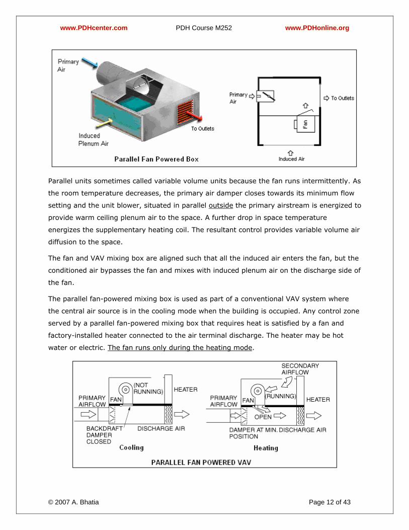
The parallel fan-powered mixing box air terminal typically consists of a primary air inlet
connection, a set of opposed blade primary air dampers, an inlet velocity sensor, a fan, a
backdraft damper, a heater, and a damper (zone) controller mounted on the side of the box
(refer figure below).
www.PDHcenter.com PDH Course M252 www.PDHonline.org
© 2007 A. Bhatia Page 12 of 43
Parallel units sometimes called variable volume units because the fan runs intermittently. As
the room temperature decreases, the primary air damper closes towards its minimum flow
setting and the unit blower, situated in parallel outside the primary airstream is energized to
provide warm ceiling plenum air to the space. A further drop in space temperature
energizes the supplementary heating coil. The resultant control provides variable volume air
diffusion to the space.
The fan and VAV mixing box are aligned such that all the induced air enters the fan, but the
conditioned air bypasses the fan and mixes with induced plenum air on the discharge side of
the fan.
The parallel fan-powered mixing box is used as part of a conventional VAV system where
the central air source is in the cooling mode when the building is occupied. Any control zone
served by a parallel fan-powered mixing box that requires heat is satisfied by a fan and
factory-installed heater connected to the air terminal discharge. The heater may be hot
water or electric. The fan runs only during the heating mode.
www.PDHcenter.com PDH Course M252 www.PDHonline.org
© 2007 A. Bhatia Page 13 of 43
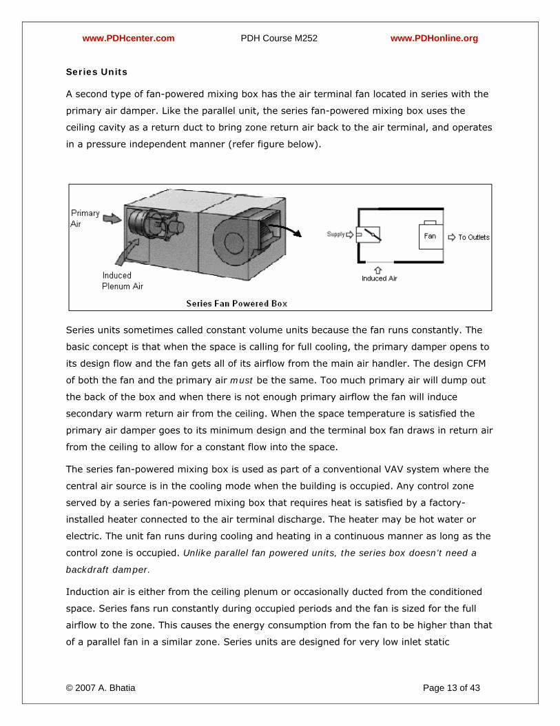
Series Units
A second type of fan-powered mixing box has the air terminal fan located in series with the
primary air damper. Like the parallel unit, the series fan-powered mixing box uses the
ceiling cavity as a return duct to bring zone return air back to the air terminal, and operates
in a pressure independent manner (refer figure below).
Series units sometimes called constant volume units because the fan runs constantly. The
basic concept is that when the space is calling for full cooling, the primary damper opens to
its design flow and the fan gets all of its airflow from the main air handler. The design CFM
of both the fan and the primary air must be the same. Too much primary air will dump out
the back of the box and when there is not enough primary airflow the fan will induce
secondary warm return air from the ceiling. When the space temperature is satisfied the
primary air damper goes to its minimum design and the terminal box fan draws in return air
from the ceiling to allow for a constant flow into the space.
The series fan-powered mixing box is used as part of a conventional VAV system where the
central air source is in the cooling mode when the building is occupied. Any control zone
served by a series fan-powered mixing box that requires heat is satisfied by a factory-
installed heater connected to the air terminal discharge. The heater may be hot water or
electric. The unit fan runs during cooling and heating in a continuous manner as long as the
control zone is occupied. Unlike parallel fan powered units, the series box doesn’t need a
backdraft damper.
Induction air is either from the ceiling plenum or occasionally ducted from the conditioned
space. Series fans run constantly during occupied periods and the fan is sized for the full
airflow to the zone. This causes the energy consumption from the fan to be higher than that
of a parallel fan in a similar zone. Series units are designed for very low inlet static

www.PDHcenter.com PDH Course M252 www.PDHonline.org
© 2007 A. Bhatia Page 14 of 43
pressures whereas in parallel units, since the mixing of a minimum primary air and induced
air takes place downstream of the terminal fan, the terminal inlet static pressure
requirement is higher. This usually adds cost at the air handler. Some studies have shown
this added cost to be in excess of the added operating cost of running the fan motors
constantly in the series terminal configuration.
Choosing Appropriate Box Type
1. Cooling only - Generally, cooling-only boxes should be used only where minimum
ventilation is not a concern and, therefore, can be set at zero. A telecommunication and
electrical room is just such a place. Another is a large open office with multiple boxes,
some serving heating and ventilation needs and others cooling only.
2. Series fan-powered – The series fan-powered mixing box is characterized by the delivery
of a constant volume of air to the control zone as the primary air stream varies. Thus it
is suited for applications that have difficult room air motion problems. Hotel atriums or
public areas with tall ceilings are good applications for the series unit.
3. Parallel fan-powered - Parallel-fan-powered boxes make sense in zones with relatively
high heating requirements, such as north-facing, perimeter zones. Energy codes, such
as ANSI/ ASHRAE/IESNA Standard 90.1, Energy Standard for Buildings except Low-Rise
Residential Buildings, and Title 24, Part 6, of the California Code of Regulations,
generally prohibit reheating more than 30 percent of maximum airflow.
4. Bypass terminals – Bypass boxes find use in mixed area applications where majority of
the building is on constant air volume and only one or two rooms require individual
temperature control. For instance a small conference room in large lobby or workshop
may be fitted with bypass terminal while balance open area can be served with constant
air volume system.
5. Reheat - Because they are less expensive, quieter, efficient and require less
maintenance than fan-powered boxes, reheat boxes could be used for most heating
applications, provided these meet all code restrictions.
CLASSIFICATION OF VAV SYSTEMS
From a controllability standpoint, the VAV terminal unit may be pressure dependent or
pressure independent.
Pressure Dependent

www.PDHcenter.com PDH Course M252 www.PDHonline.org
© 2007 A. Bhatia Page 15 of 43
A device is said to be pressure dependent when the flow rate passing through it varies as
the system inlet pressure fluctuates. The flow rate is dependent on both the inlet pressure
and the damper position of the terminal unit.
The pressure dependent terminal unit consists of a damper and a damper actuator
controlled directly by a room thermostat. The actuator is modified in response to room
temperature only and acts as a damper positioner. Pressure dependent terminals do not
have controls (flow sensor or reset controller) that compensate for changes in duct static
pressure.
Since the air volume varies with inlet pressure, the room may experience temperature
swings until the thermostat repositions the damper. Excessive airflow may also lead to
unacceptable noise levels in the space.
Pressure Independent
A device is said to be pressure independent when the flow rate passing through it is
maintained constant regardless of variations in system inlet pressure. The pressure
independent control is achieved with the addition of a flow sensor and flow controller to the
VAV box. The controller maintains a preset volume by measuring the flow through the inlet
and modulating the damper in response to the flow signal. The preset volume can be varied
between the calibrated minimum and the maximum limits by the thermostat output.
With pressure independent systems, airflow is independent of upstream static pressure
changes. Overshooting and undershooting of supply air is eliminated and system stability
is enhanced. Typically, this type of control will incorporate a maximum flow setting, and
often a minimum flow setting, which can be factory set. The maximum flow setting is most
typically used when terminal reheat is incorporated. This capability, as well as being
pressure compensated, greatly reduces the amount of time and expense associated with
field air balancing or the need to rebalance after building tenant changes.
We will discuss the VAV control configurations further in the forthcoming sections.
VAV Control Elements
There are three basic elements of the HVAC control: sensor, controller, and controlled
device. A sensor measures the temperature of the air and passes the information on to the
controller. The controller compares the air temperature to a set point, and then sends a
signal to open or close the controlled device, which is typically an actuator for air valve.
www.PDHcenter.com PDH Course M252 www.PDHonline.org
© 2007 A. Bhatia Page 16 of 43
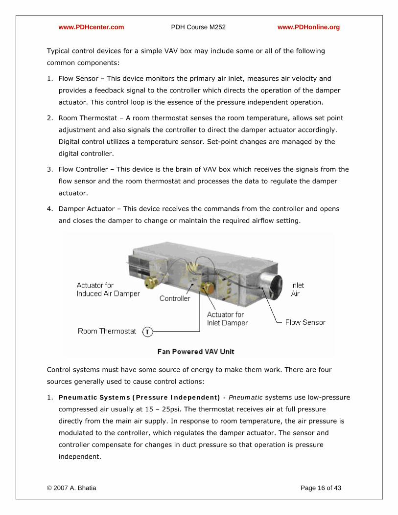
Typical control devices for a simple VAV box may include some or all of the following
common components:
1. Flow Sensor – This device monitors the primary air inlet, measures air velocity and
provides a feedback signal to the controller which directs the operation of the damper
actuator. This control loop is the essence of the pressure independent operation.
2. Room Thermostat – A room thermostat senses the room temperature, allows set point
adjustment and also signals the controller to direct the damper actuator accordingly.
Digital control utilizes a temperature sensor. Set-point changes are managed by the
digital controller.
3. Flow Controller – This device is the brain of VAV box which receives the signals from the
flow sensor and the room thermostat and processes the data to regulate the damper
actuator.
4. Damper Actuator – This device receives the commands from the controller and opens
and closes the damper to change or maintain the required airflow setting.
Control systems must have some source of energy to make them work. There are four
sources generally used to cause control actions:
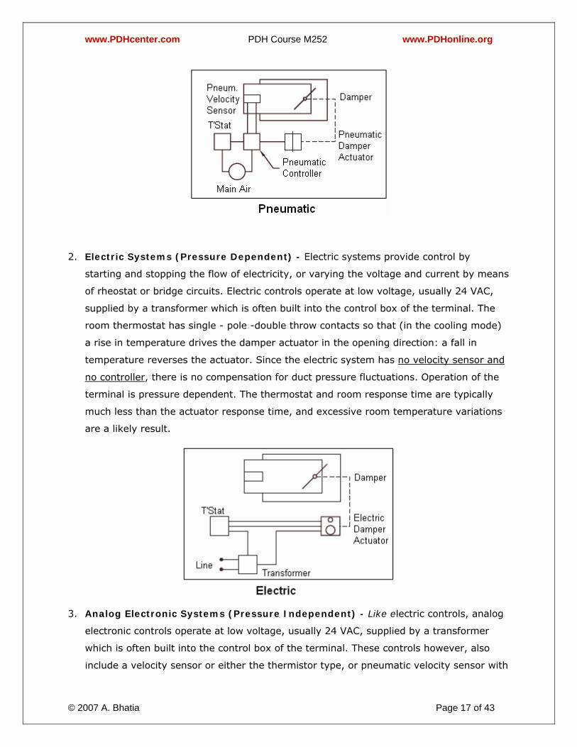
1. Pneumatic Systems (Pressure Independent) - Pneumatic systems use low-pressure
compressed air usually at 15 – 25psi. The thermostat receives air at full pressure
directly from the main air supply. In response to room temperature, the air pressure is
modulated to the controller, which regulates the damper actuator. The sensor and
controller compensate for changes in duct pressure so that operation is pressure
independent.
www.PDHcenter.com PDH Course M252 www.PDHonline.org
© 2007 A. Bhatia Page 17 of 43
2. Electric Systems (Pressure Dependent) - Electric systems provide control by
starting and stopping the flow of electricity, or varying the voltage and current by means
of rheostat or bridge circuits. Electric controls operate at low voltage, usually 24 VAC,
supplied by a transformer which is often built into the control box of the terminal. The
room thermostat has single - pole -double throw contacts so that (in the cooling mode)
a rise in temperature drives the damper actuator in the opening direction: a fall in
temperature reverses the actuator. Since the electric system has no velocity sensor and
no controller, there is no compensation for duct pressure fluctuations. Operation of the
terminal is pressure dependent. The thermostat and room response time are typically
much less than the actuator response time, and excessive room temperature variations
are a likely result.
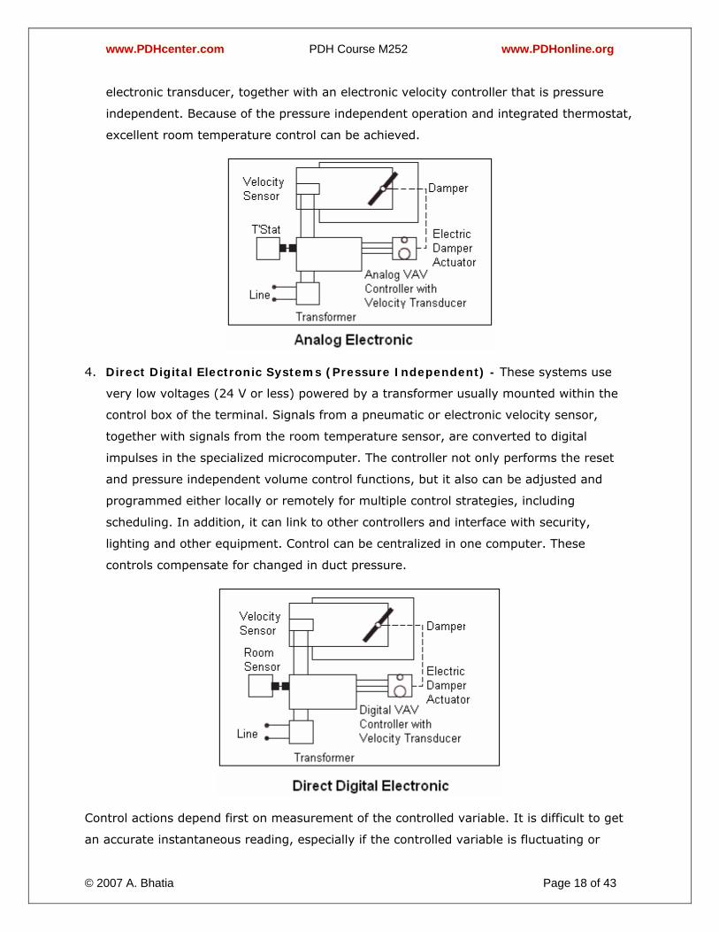
3. Analog Electronic Systems (Pressure Independent) - Like electric controls, analog
electronic controls operate at low voltage, usually 24 VAC, supplied by a transformer
which is often built into the control box of the terminal. These controls however, also
include a velocity sensor or either the thermistor type, or pneumatic velocity sensor with
www.PDHcenter.com PDH Course M252 www.PDHonline.org
© 2007 A. Bhatia Page 18 of 43
electronic transducer, together with an electronic velocity controller that is pressure
independent. Because of the pressure independent operation and integrated thermostat,
excellent room temperature control can be achieved.
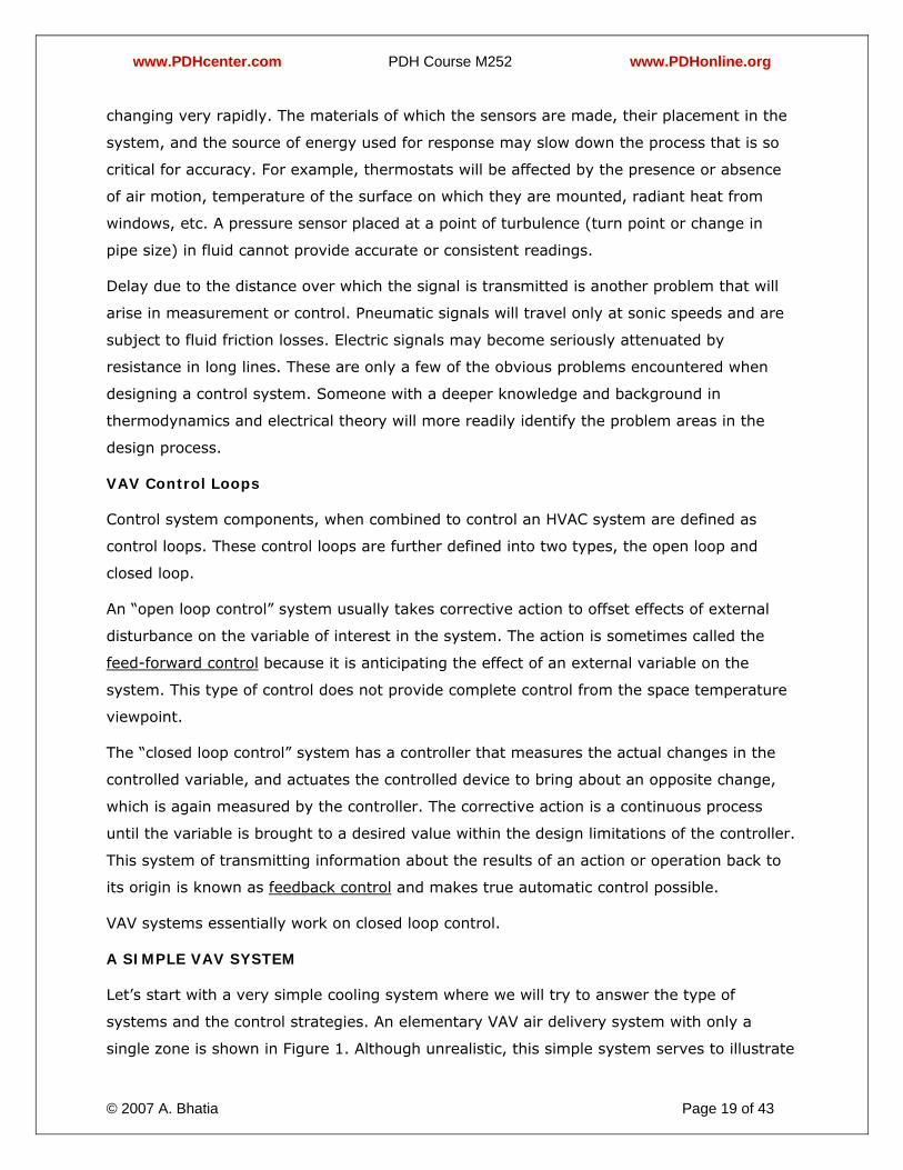
4. Direct Digital Electronic Systems (Pressure Independent) - These systems use
very low voltages (24 V or less) powered by a transformer usually mounted within the
control box of the terminal. Signals from a pneumatic or electronic velocity sensor,
together with signals from the room temperature sensor, are converted to digital
impulses in the specialized microcomputer. The controller not only performs the reset
and pressure independent volume control functions, but it also can be adjusted and
programmed either locally or remotely for multiple control strategies, including
scheduling. In addition, it can link to other controllers and interface with security,
lighting and other equipment. Control can be centralized in one computer. These
controls compensate for changed in duct pressure.
Control actions depend first on measurement of the controlled variable. It is difficult to get
an accurate instantaneous reading, especially if the controlled variable is fluctuating or
www.PDHcenter.com PDH Course M252 www.PDHonline.org
© 2007 A. Bhatia Page 19 of 43
changing very rapidly. The materials of which the sensors are made, their placement in the
system, and the source of energy used for response may slow down the process that is so
critical for accuracy. For example, thermostats will be affected by the presence or absence
of air motion, temperature of the surface on which they are mounted, radiant heat from
windows, etc. A pressure sensor placed at a point of turbulence (turn point or change in
pipe size) in fluid cannot provide accurate or consistent readings.
Delay due to the distance over which the signal is transmitted is another problem that will
arise in measurement or control. Pneumatic signals will travel only at sonic speeds and are
subject to fluid friction losses. Electric signals may become seriously attenuated by
resistance in long lines. These are only a few of the obvious problems encountered when
designing a control system. Someone with a deeper knowledge and background in
thermodynamics and electrical theory will more readily identify the problem areas in the
design process.
VAV Control Loops
Control system components, when combined to control an HVAC system are defined as
control loops. These control loops are further defined into two types, the open loop and
closed loop.
An “open loop control” system usually takes corrective action to offset effects of external
disturbance on the variable of interest in the system. The action is sometimes called the
feed-forward control because it is anticipating the effect of an external variable on the
system. This type of control does not provide complete control from the space temperature
viewpoint.
The “closed loop control” system has a controller that measures the actual changes in the
controlled variable, and actuates the controlled device to bring about an opposite change,
which is again measured by the controller. The corrective action is a continuous process
until the variable is brought to a desired value within the design limitations of the controller.
This system of transmitting information about the results of an action or operation back to
its origin is known as feedback control and makes true automatic control possible.
VAV systems essentially work on closed loop control.
A SIMPLE VAV SYSTEM
Let’s start with a very simple cooling system where we will try to answer the type of
systems and the control strategies. An elementary VAV air delivery system with only a
single zone is shown in Figure 1. Although unrealistic, this simple system serves to illustrate
www.PDHcenter.com PDH Course M252 www.PDHonline.org
© 2007 A. Bhatia Page 20 of 43
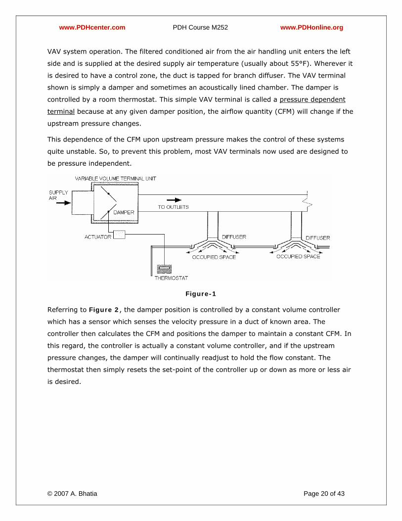
VAV system operation. The filtered conditioned air from the air handling unit enters the left
side and is supplied at the desired supply air temperature (usually about 55°F). Wherever it
is desired to have a control zone, the duct is tapped for branch diffuser. The VAV terminal
shown is simply a damper and sometimes an acoustically lined chamber. The damper is
controlled by a room thermostat. This simple VAV terminal is called a pressure dependent
terminal because at any given damper position, the airflow quantity (CFM) will change if the
upstream pressure changes.
This dependence of the CFM upon upstream pressure makes the control of these systems
quite unstable. So, to prevent this problem, most VAV terminals now used are designed to
be pressure independent.
Figure-1
Referring to Figure 2, the damper position is controlled by a constant volume controller
which has a sensor which senses the velocity pressure in a duct of known area. The
controller then calculates the CFM and positions the damper to maintain a constant CFM. In
this regard, the controller is actually a constant volume controller, and if the upstream
pressure changes, the damper will continually readjust to hold the flow constant. The
thermostat then simply resets the set-point of the controller up or down as more or less air
is desired.

www.PDHcenter.com PDH Course M252 www.PDHonline.org
© 2007 A. Bhatia Page 21 of 43
Figure-2
Another feature of the constant volume controller is that the maximum flow quantity and
the minimum flow quantity can be set – the maximum to the design flow for the zone and
the minimum to the minimum amount required for effective air distribution or the
ventilation requirement – whichever is greater.
If the minimum flow quantity exceeds the air flow that would be necessary to maintain the
space dry bulb set-point at any time the building is occupied, the space will overcool. A
typical example of this would be an interior office or conference room. Under conditions of
partial occupancy and low loads, the room temperature can approach the supply air
temperature. (This has been referred to as the "ice box effect").
To prevent this type of overcooling, several techniques have been employed. One is the
variable air volume reheat terminal. A variable air volume reheat terminal is shown
diagrammatically in Figure 3. The reheat coil has been added to the terminal, and the
control sequence is that with a drop in room temperature below set-point, the volume
damper will modulate to its minimum value, and a further drop in temperature will cause
the reheat coil valve to start modulating open.
www.PDHcenter.com PDH Course M252 www.PDHonline.org
© 2007 A. Bhatia Page 22 of 43
Figure-3
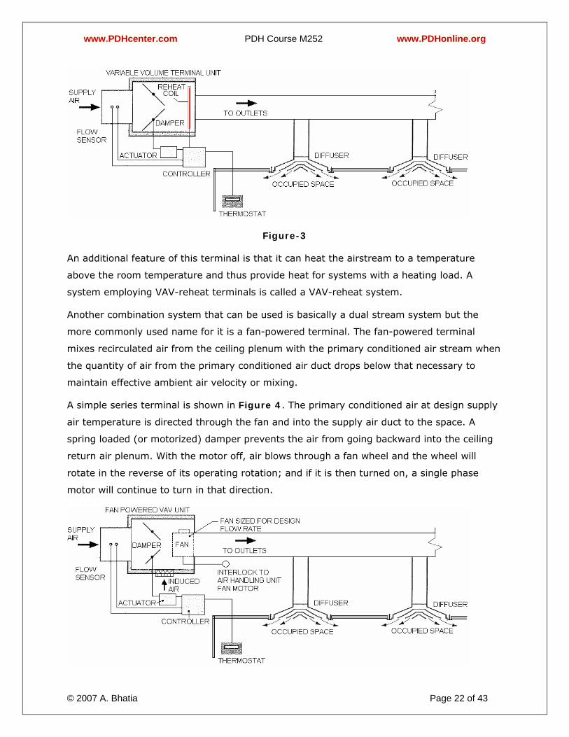
An additional feature of this terminal is that it can heat the airstream to a temperature
above the room temperature and thus provide heat for systems with a heating load. A
system employing VAV-reheat terminals is called a VAV-reheat system.
Another combination system that can be used is basically a dual stream system but the
more commonly used name for it is a fan-powered terminal. The fan-powered terminal
mixes recirculated air from the ceiling plenum with the primary conditioned air stream when
the quantity of air from the primary conditioned air duct drops below that necessary to
maintain effective ambient air velocity or mixing.
A simple series terminal is shown in Figure 4. The primary conditioned air at design supply
air temperature is directed through the fan and into the supply air duct to the space. A
spring loaded (or motorized) damper prevents the air from going backward into the ceiling
return air plenum. With the motor off, air blows through a fan wheel and the wheel will
rotate in the reverse of its operating rotation; and if it is then turned on, a single phase
motor will continue to turn in that direction.
www.PDHcenter.com PDH Course M252 www.PDHonline.org
© 2007 A. Bhatia Page 23 of 43
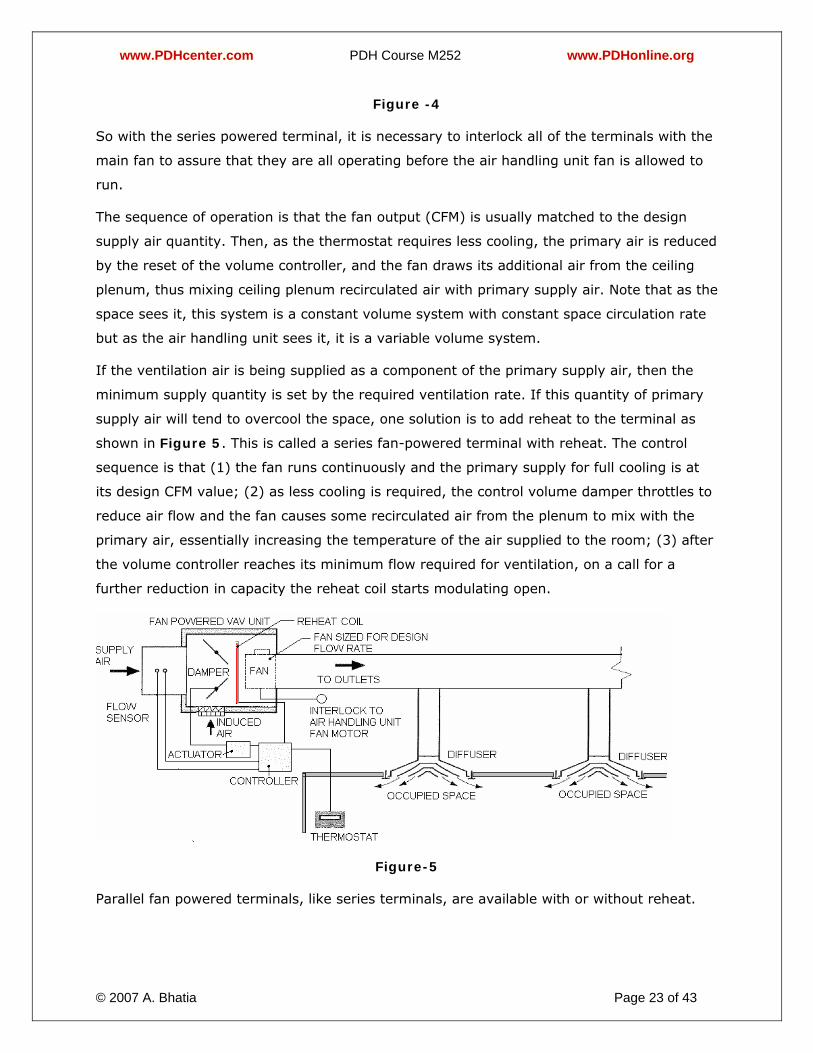
Figure -4
So with the series powered terminal, it is necessary to interlock all of the terminals with the
main fan to assure that they are all operating before the air handling unit fan is allowed to
run.
The sequence of operation is that the fan output (CFM) is usually matched to the design
supply air quantity. Then, as the thermostat requires less cooling, the primary air is reduced
by the reset of the volume controller, and the fan draws its additional air from the ceiling
plenum, thus mixing ceiling plenum recirculated air with primary supply air. Note that as the
space sees it, this system is a constant volume system with constant space circulation rate
but as the air handling unit sees it, it is a variable volume system.
If the ventilation air is being supplied as a component of the primary supply air, then the
minimum supply quantity is set by the required ventilation rate. If this quantity of primary
supply air will tend to overcool the space, one solution is to add reheat to the terminal as
shown in Figure 5. This is called a series fan-powered terminal with reheat. The control
sequence is that (1) the fan runs continuously and the primary supply for full cooling is at
its design CFM value; (2) as less cooling is required, the control volume damper throttles to
reduce air flow and the fan causes some recirculated air from the plenum to mix with the
primary air, essentially increasing the temperature of the air supplied to the room; (3) after
the volume controller reaches its minimum flow required for ventilation, on a call for a
further reduction in capacity the reheat coil starts modulating open.
Figure-5
Parallel fan powered terminals, like series terminals, are available with or without reheat.
www.PDHcenter.com PDH Course M252 www.PDHonline.org
© 2007 A. Bhatia Page 24 of 43
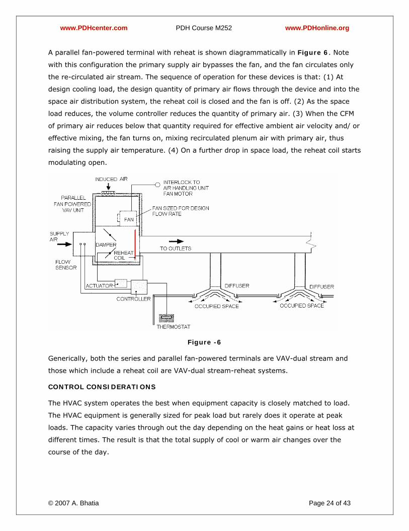
A parallel fan-powered terminal with reheat is shown diagrammatically in Figure 6. Note
with this configuration the primary supply air bypasses the fan, and the fan circulates only
the re-circulated air stream. The sequence of operation for these devices is that: (1) At
design cooling load, the design quantity of primary air flows through the device and into the
space air distribution system, the reheat coil is closed and the fan is off. (2) As the space
load reduces, the volume controller reduces the quantity of primary air. (3) When the CFM
of primary air reduces below that quantity required for effective ambient air velocity and/ or
effective mixing, the fan turns on, mixing recirculated plenum air with primary air, thus
raising the supply air temperature. (4) On a further drop in space load, the reheat coil starts
modulating open.
Figure -6
Generically, both the series and parallel fan-powered terminals are VAV-dual stream and
those which include a reheat coil are VAV-dual stream-reheat systems.
CONTROL CONSIDERATIONS
The HVAC system operates the best when equipment capacity is closely matched to load.
The HVAC equipment is generally sized for peak load but rarely does it operate at peak
loads. The capacity varies through out the day depending on the heat gains or heat loss at
different times. The result is that the total supply of cool or warm air changes over the
course of the day.
www.PDHcenter.com PDH Course M252 www.PDHonline.org
© 2007 A. Bhatia Page 25 of 43
How is this accomplished? The obvious answer is an automatic compensating control system
that minimizes human intervention and the chance of human error.
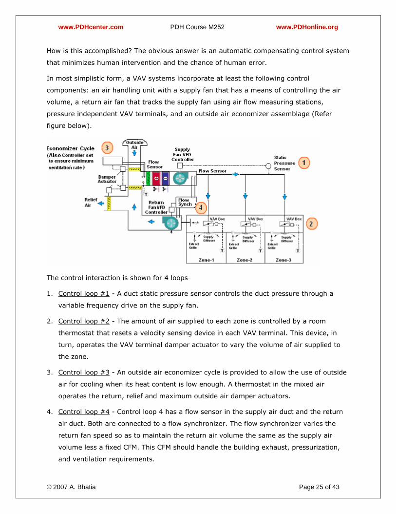
In most simplistic form, a VAV systems incorporate at least the following control
components: an air handling unit with a supply fan that has a means of controlling the air
volume, a return air fan that tracks the supply fan using air flow measuring stations,
pressure independent VAV terminals, and an outside air economizer assemblage (Refer
figure below).
The control interaction is shown for 4 loops-
1. Control loop #1 - A duct static pressure sensor controls the duct pressure through a
variable frequency drive on the supply fan.
2. Control loop #2 - The amount of air supplied to each zone is controlled by a room
thermostat that resets a velocity sensing device in each VAV terminal. This device, in
turn, operates the VAV terminal damper actuator to vary the volume of air supplied to
the zone.
3. Control loop #3 - An outside air economizer cycle is provided to allow the use of outside
air for cooling when its heat content is low enough. A thermostat in the mixed air
operates the return, relief and maximum outside air damper actuators.
4. Control loop #4 - Control loop 4 has a flow sensor in the supply air duct and the return
air duct. Both are connected to a flow synchronizer. The flow synchronizer varies the
return fan speed so as to maintain the return air volume the same as the supply air
volume less a fixed CFM. This CFM should handle the building exhaust, pressurization,
and ventilation requirements.
www.PDHcenter.com PDH Course M252 www.PDHonline.org
© 2007 A. Bhatia Page 26 of 43
For example, if the temperature in Zone 3 drops, the damper on the terminal supplying this
zone will start to close. When this occurs the supply duct pressure will increase, thereby
increasing the flow through the other terminals. The pressure independent controls will
react to close their dampers and the duct pressure will increase more. The static pressure
sensor (control loop #1) will then lower the duct static pressure by reducing the speed of
the supply fan. When this happens, the fan tracking loop #4 and will reduce the speed of
the return fan so that the return air flow is reduced. When this reduction occurs, the mixed
air temperature changes and the thermostat in the mixing box will change the economizer
damper positions (control loop # 3). This is how the system operates.
All four of the control loops incorporate either pressure or temperature sensors with very
fast response times. The supply fan changes speed almost immediately with a change in
duct static pressure. The return fan responds immediately to changes in duct air velocity
sensed by the air flow measuring stations. The mixed air thermostat responds almost
instantly to a change in temperature resulting from a change in flow of outside and return
air. This changes the economizer damper position thereby instantly changing the system
pressure. Too many of the spontaneous control actions may lead to system’s instability
leading to hunting and shortening the life of the actuators.
The use of a relief fan rather than a flow tracking return fan can eliminate the most
troublesome control loop problems and will also enable the engineer to properly size and
characterize the outside and return dampers so that changes in damper position will not
change the mixed air plenum pressure (Refer figure below). This method eliminates the
interaction between the economizer damper position and the supply duct static pressure
sensor. Properly sizing and characterizing the economizer dampers and using a relief fan will
also minimize the gusty wind effect on the outside air intake and relief air openings. Note
that a forty-five mile an hour wind gust against a louver is equivalent to an air pressure
change of 1in-H2O. This can wreak havoc with the mixed air thermostat and duct pressure
controls. In many installations, the gusty wind pressure is great enough to blow into the
relief louver and on into the mixed air plenum.
www.PDHcenter.com PDH Course M252 www.PDHonline.org
© 2007 A. Bhatia Page 27 of 43
Most small commercial buildings do not require pressure independent VAV terminals nor can
their additional cost and maintenance justify their use. Using correctly sized pressure
dependent terminals will largely eliminate one interacting control loop. It is very important
that all the controllers, actuators and other control devices should be matched for their
response times and shall be supplied by same company.
VAV SYSTEM DESIGN & CHALLENGES
Generally the design considerations governing constant volume air conditioning systems can
be applied to the design of air handling and distribution equipment for variable volume
systems.
VAV AIR-HANDLER SIZING
The sizing of a VAV AHU is slightly different from the sizing of a CAV AHU.
With a CAV system it is common practice to size the AHU based on the worst case heat load
of the space. When sizing an AHU for a VAV system, the engineer should do heat load
calculations for each VAV box zone at different times of the day. The size of the VAV AHU is
then based on worst case summation of zone loads. Not all VAV zones will be at maximum
heat load at the same time of the day. This is called a diversity factor. Because of the
diversity factor inherent in VAV systems, it is possible to shrink the capacity requirements of
the VAV AHU by ten to fifteen percent when compared to a CAV AHU.
The BTU/ft2 is sometimes used as a rule of thumb benchmark for AHU sizing. If a CAV AHU
is sized with a capacity of 50 - 55 BTU/ft2 the VAV AHU can be sized with a capacity of 40-
45 BTU/ft2. Reducing the capacity of the AHU reduces the cost of the equipment and the
physical space requirements.

www.PDHcenter.com PDH Course M252 www.PDHonline.org
© 2007 A. Bhatia Page 28 of 43
VENTILATION CONTROL WITH VAV SYSTEM
A minimum outdoor airflow must be introduced in most air handling systems to ensure good
IAQ and to pressurize the building. The amount of ventilation air is determined in
accordance with ASHRAE Standard 62-89, which requires a minimum of 20 CFM per person.
Ventilation airflow is obtained by multiplying the recommended ventilation rate by the
maximum number of occupants in the space. This value becomes the design ventilation rate
to be delivered during all occupied periods. In constant volume systems, once the system is
properly designed, installed and balanced, it will always provide this fixed value of
ventilation and is normally expressed as fixed percentage of the total air.
This approach may not however provide the required flow under all operating conditions in
VAV systems where the pressure and flow relationships vary with load. As the load
decreases, less outdoor air may be brought into the system as the VAV system turns down.
If the load change is not proportional to the occupancy change, then inadequate minimum
outside air may result from the VAV system turn down. It is critical that the system be set
up to provide the required minimum outdoor air flow rate and then maintained in a manner
that ensures this.
Numerous methods of system design and control have been used to achieve required
ventilation with VAV systems, some of which are:
1. Modulate the outdoor air damper based on measurement of outdoor airflow. For
instance, if the system is designed for 20% minimum outdoor air, then a minimum
position signal equal to 20% of the actuator span is set for outdoor air dampers.
Typically the damper is interlocked to open when the unit is in operation and in an
occupied cycle and closed when the unit is shut down. This modulating damper method
can also allow CO2 based demand ventilation control to reduce airflow when spaces have
low occupancy. The minimum outdoor air set point can be a fixed value set for the
design minimum flow rate or can be a variable based on occupancy, CO2 level or some
other parameter.
2. Modulate the speed of the return air fan to hold a fixed negative pressure in a static
mixing chamber.
3. Modulate the return air fan speed to maintain a fixed air flow (CFM) differential between
the supply and return air fans.
4. Provide a ventilating stream fan of fixed air flow quantity and a companion relief fan
with control logic to continually rebalance the building ventilation systems.
www.PDHcenter.com PDH Course M252 www.PDHonline.org
© 2007 A. Bhatia Page 29 of 43
5. Provide an Independent Make Up Air Handling System
The last option provides the simplest and least costly of the five and when properly applied,
provides the best performance. Here a dedicated 100% makeup air handling unit (MAH)
treats all of the make-up air and supplies it to recirculating air handling (RAH) systems.
The MAH unit will be sized for treating the outdoor air that comes into the building for (1)
for ventilation/indoor air quality and make up air, (2) for the economizer cycle to meet
cooling loads and (3) for pressurizing the building and control infiltration. The MAH unit will
consist of blower, cooling coil, preheat coil and filter and shall be sized to meet both the
sensible and latent loads of outdoor air. The MAH unit will be considerably smaller and does
not have any provision for recirculation. The RAH will be sized to meet all the internal heat
loads resulting due to solar heat gain, people and auxiliary heat sources such as lighting and
equipment. The humidity load can be considered negligible.
Alternatively, a completely independent MAH system may also be considered that will
provide the treated outdoor air directly to the space. Here the MAH will use separate ducted
fresh air ventilation path to the spaces. The advantage of this approach is that the
ventilation air gets directly to the occupied space and the system can easily accommodate
after hours humidity and temperature control. The buildings for tenants use will especially
be benefited since they can be billed individually for their respective RAH usage. Because
the outdoor air is delivered directly to the space, the RAH units will not be required to
operate during unoccupied periods.
A recent innovation in VAV system design is the ability to modulate a zone VAV box to
consider both temperature control and CO2 based demand ventilation control. In this type of
system, ventilation is not limited by the space load requirements but is controlled separately
using a CO2 sensor in each major occupied zone. In this case the signal from the CO2 sensor
modulates the local VAV box and the outside air intake to ensure all spaces have adequate
ventilation.
HOW TO SPECIFY VAV BOXES
Two parameters are generally specified for selection of VAV boxes:
1. The maximum CFM required to be delivered under full load (based on heat load
calculations)
2. The noise level required (a noise level of NC55 is commonly applied in an office area)
www.PDHcenter.com PDH Course M252 www.PDHonline.org
© 2007 A. Bhatia Page 30 of 43
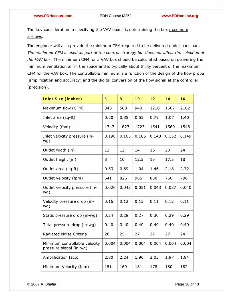
The key consideration in specifying the VAV boxes is determining the box maximum
airflows.
The engineer will also provide the minimum CFM required to be delivered under part load.
The minimum CFM is used as part of the control strategy but does not affect the selection of
the VAV box. The minimum CFM for a VAV box should be calculated based on delivering the
minimum ventilation air in the space and is typically about thirty percent of the maximum
CFM for the VAV box. The controllable minimum is a function of the design of the flow probe
(amplification and accuracy) and the digital conversion of the flow signal at the controller
(precision).
Inlet Size (inches) 6 8 10 12 14 16
Maximum flow (CFM) 343 568 940 1210 1667 2162
Inlet area (sq-ft) 0.20 0.35 0.55 0.79 1.07 1.40
Velocity (fpm) 1747 1627 1723 1541 1560 1548
Inlet velocity pressure (in-wg)
0.190 0.165 0.185 0.148 0.152 0.149
Outlet width (in) 12 12 14 16 20 24
Outlet height (in) 8 10 12.5 15 17.5 18
Outlet area (sq-ft) 0.53 0.69 1.04 1.46 2.18 2.72
Outlet velocity (fpm) 641 826 905 830 766 796
Outlet velocity pressure (in-wg)
0.026 0.043 0.051 0.043 0.037 0.040
Velocity pressure drop (in-wg)
0.16 0.12 0.13 0.11 0.12 0.11
Static pressure drop (in-wg) 0.24 0.28 0.27 0.30 0.29 0.29
Total pressure drop (in-wg) 0.40 0.40 0.40 0.40 0.40 0.40
Radiated Noise Criteria 28 25 27 27 27 24
Minimum controllable velocity pressure signal (in-wg)
0.004 0.004 0.004 0.004 0.004 0.004
Amplification factor 2.80 2.24 1.96 2.03 1.97 1.94
Minimum Velocity (fpm) 151 169 181 178 180 182
www.PDHcenter.com PDH Course M252 www.PDHonline.org
© 2007 A. Bhatia Page 31 of 43
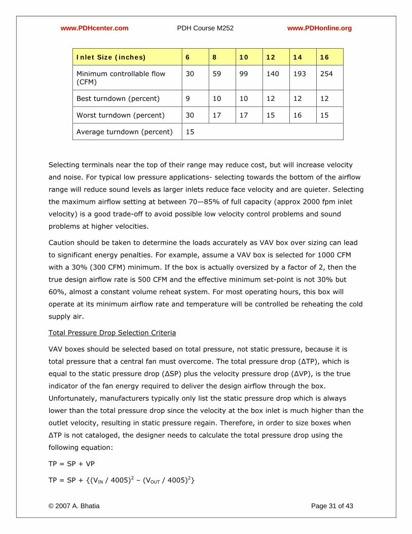
Inlet Size (inches) 6 8 10 12 14 16
Minimum controllable flow (CFM)
30 59 99 140 193 254
Best turndown (percent) 9 10 10 12 12 12
Worst turndown (percent) 30 17 17 15 16 15
Average turndown (percent) 15
Selecting terminals near the top of their range may reduce cost, but will increase velocity
and noise. For typical low pressure applications- selecting towards the bottom of the airflow
range will reduce sound levels as larger inlets reduce face velocity and are quieter. Selecting
the maximum airflow setting at between 70—85% of full capacity (approx 2000 fpm inlet
velocity) is a good trade-off to avoid possible low velocity control problems and sound
problems at higher velocities.
Caution should be taken to determine the loads accurately as VAV box over sizing can lead
to significant energy penalties. For example, assume a VAV box is selected for 1000 CFM
with a 30% (300 CFM) minimum. If the box is actually oversized by a factor of 2, then the
true design airflow rate is 500 CFM and the effective minimum set-point is not 30% but
60%, almost a constant volume reheat system. For most operating hours, this box will
operate at its minimum airflow rate and temperature will be controlled be reheating the cold
supply air.
Total Pressure Drop Selection Criteria
VAV boxes should be selected based on total pressure, not static pressure, because it is
total pressure that a central fan must overcome. The total pressure drop (∆TP), which is
equal to the static pressure drop (∆SP) plus the velocity pressure drop (∆VP), is the true
indicator of the fan energy required to deliver the design airflow through the box.
Unfortunately, manufacturers typically only list the static pressure drop which is always
lower than the total pressure drop since the velocity at the box inlet is much higher than the
outlet velocity, resulting in static pressure regain. Therefore, in order to size boxes when
∆TP is not cataloged, the designer needs to calculate the total pressure drop using the
following equation:
TP = SP + VP
TP = SP + {(VIN / 4005)2 – (VOUT / 4005)2}
www.PDHcenter.com PDH Course M252 www.PDHonline.org
© 2007 A. Bhatia Page 32 of 43
TP = SP + {[4 * CFM / (4005* 3.14 * D2)] 2 – [CFM / (4005 * W * H)] 2}
Where
TP = Total pressure drop
SP = Static pressure drop
VP = Velocity pressure drop
Vin = Inlet velocity
Vout = Outlet velocity
CFM = airflow rate
D = box inlet diameter (feet)
W = Inside width of the box outlet
H = Inside height of the box outlet
Selecting and controlling VAV boxes has a significant impact on HVAC energy use and
comfort control. The larger a VAV box is, the lower its pressure drop, and in turn, the lower
the fan energy. However, the larger VAV box will require a higher minimum airflow set-
point, which in turn will increase the amount of reheat and fan energy. Simulations were
made to determine the optimum balance from an energy perspective between pressure drop
and minimum set-point limitations. For most applications, the analysis indicates that the
VAV boxes should be selected for a total pressure drop of about 0.5” H2O.
Amplification
Most manufacturers use a velocity-pressure sensor that provides an amplified signal to the
VAV-box controller. The shape of the sensor determines the amount of amplification it can
provide, as well as the amount of noise and pressure drop it creates. The greater the
amplification, the lower will be the minimum controllable airflow.
While all manufacturers claim that their patented airflow sensors provide better
amplification, this may be at the expense of higher pressure drop. Similarly, comparing the
VAV boxes on pressure drop alone may not be fair because a VAV box with a low pressure
drop could have poor amplification. A better metric for comparing VAV boxes is turndown
(i.e., the ratio of minimum controllable airflow to maximum airflow). Although amplification
typically is not included in VAV-box schedules, requirements for amplification and/or
turndown are good to include in specifications.
www.PDHcenter.com PDH Course M252 www.PDHonline.org
© 2007 A. Bhatia Page 33 of 43
Noise
VAV box manufacturers provide two types of sound data: discharge and radiated. Discharge
noise is rarely an issue if the box has hard duct on the inlet, a lined outlet plenum and flex
duct between the plenum and diffusers.
VAV boxes should not be located over noise sensitive areas when an acoustical tile ceiling
system is being used. A gypsum board ceiling will do a better job of reducing VAV radiated
noise than a typical ceiling tile system. For this reason most VAV boxes can be located
above noise-sensitive areas where a gypsum board ceiling, which has all penetrations and
joints well sealed, is installed. Over sizing VAV boxes is one way to reduce radiated and
discharge noise levels. This has to do with the velocity of air as it enters the box and passes
by the damper. Static pressure drop across the VAV box also has an impact on the amount
of noise generated. Designing the system so that the damper does not produce more than
0.5 in. of static pressure drop will minimize noise.
As a general rule, VAV boxes located above standard ceilings should have radiated Noise
Criteria (NC) levels no more than ~5 NC above the desired room NC rating. For example, a
typical office application with a desired NC level of 30, the VAV box should be selected for a
35 NC. Note that the assumptions used by manufacturers in determining resulting NC levels
should be checked to make sure they apply (see catalog data and ARI rating assumptions).
If not, then a more complex calculation using radiated sound power data must be done.
Compatibility with Air Terminal Diffusers
The function of an air diffuser is to supply cold or warm air to an occupied space evenly,
without causing excessive air movement at any particular point in the room while at the
same time providing near-uniform temperatures throughout the occupied zone. To achieve
optimum performance from a diffuser, it must introduce air above the occupied zone at a
velocity high enough to mix well with room air. With an improperly selected diffuser, low air
flow will cause "dumping" of cold air and other air distribution problems in the space.
Dumping means that the air leaving the diffuser does not have sufficient velocity to hug the
ceiling (the so-called Coanda effect) and mix with the room air before reaching the occupied
portion of the room. Instead, a jet of cold air descends into the occupied space creating
draft and cold temperatures which in turn creates discomfort. The industry quantifies
diffuser performance with the Air Diffusion Performance Index (ADPI). An ADPI of 70 to 80
is considered acceptable. The ASHRAE Handbook of Fundamentals gives ranges of T50/L for
various diffuser types that result in various ADPI goals. L is the characteristic room length
www.PDHcenter.com PDH Course M252 www.PDHonline.org
© 2007 A. Bhatia Page 34 of 43
(e.g., distance from the outlet to the wall or mid-plane between outlets) and T50 is the
“throw @ 50 FPM” or in other words is the distance from the outlet at which the supply air
velocity drops to 50 feet per minute. For a perforated ceiling diffuser, the acceptable ADPI
will result when T50/L ranges from 1.0 to 3.4. This basically means that best turndown
possible while still maintaining an acceptable ADPI is 1/3.4 = 30% turndown. There are
many buildings operating comfortably with lower than 30% airflow minimums. Research at
UC Berkeley and Lawrence Berkeley National Laboratory indicates that in cooling mode ADPI
depends more on the diffuser type than the flow rate. When designing the diffusers layout,
the designer must consider diffusers with good throw characteristics at low load. In VAV
systems, linear slot diffusers are usually preferred to traditional square diffusers. Since
linear slot diffusers have a plenum attached to the register, they can more evenly distribute
air at times when the delivered air volume is low. With slot diffusers, lower volumes are
discharged at higher jet velocities. Other types of diffusers that have greater turndown are
the swirl diffuser and light troffer diffuser. A light troffer diffuser, for example, can turndown
almost to zero and still maintain acceptable ADPI. If a traditional square diffuser is used on
a VAV system, a "puddling" effect often occurs where the cold air just drops to the floor,
instead of being circulated around the room.
Note that ADPI tests are always done under a cooling load. To achieve good air distribution
even when the airflow rate is low, maintaining diffuser throw is most important.
ZONE TEMPERATURE SENSORS
To the building occupant, the zone temperature sensor is the most visible part of the
system.
In CAV system, a single temperature sensor is typically installed in the return air duct to
measure the average space temperature. One of the advantages of VAV systems is the
ability to have a separate temperature sensor to control each zone. The location of the zone
temperature sensor is an important issue. Going back to basics, we remember that the
control system will try to achieve the desired set-point at the location where the
temperature sensor is located and therefore the location of the temperature sensor can
impact the comfort level in the entire zone.
For example, if a single VAV box supplies two closed offices, the system will achieve the set-
point in the office that has the temperature sensor while the other office (the office without
the temperature sensor) will be "floating".
www.PDHcenter.com PDH Course M252 www.PDHonline.org
© 2007 A. Bhatia Page 35 of 43
It is not a good idea to mount temperature sensors on exterior walls because exterior walls
scan transmit heat from the outside making the temperature sensor think that the room is
warm. This can cause overcooling in the room.
The adjustment of the diffusers and the placement of partitions and other large objects in
the space impacts air distribution. It is therefore important to place the temperature sensor
at about body height (about 5 feet from the floor) so that stratification and air pockets do
not cause overcooling or under-cooling in the space. Temperature sensor shall also be
placed away from heat sources. Overcooling of the space will also occur if a temperature
sensor is located such that it is exposed to a heat source such as direct sunlight, a kettle or
the condenser coils of a refrigerator.
VAV SYSTEM ZONING
When beginning a concept plan for a building, the designer is usually just given an empty
floor plan. In absence of partition layout and type of occupancy, the designer has to decide
the zones, balancing flexibility and control options by experience and judgment.
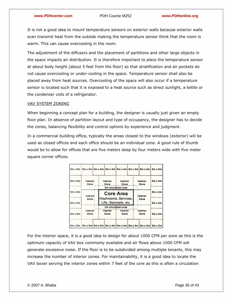
In a commercial building office, typically the areas closest to the windows (exterior) will be
used as closed offices and each office should be an individual zone. A good rule of thumb
would be to allow for offices that are five meters deep by four meters wide with five meter
square corner offices.
For the interior space, it is a good idea to design for about 1000 CFM per zone as this is the
optimum capacity of VAV box commonly available and air flows above 1000 CFM will
generate excessive noise. If the floor is to be subdivided among multiple tenants, this may
increase the number of interior zones. For maintainability, it is a good idea to locate the
VAV boxer serving the interior zones within 7 feet of the core as this is often a circulation
www.PDHcenter.com PDH Course M252 www.PDHonline.org
© 2007 A. Bhatia Page 36 of 43
area and easily accessible. Though the VAV box is mounted close to the core, the actual
diffusers for the interior zone will be distributed though out the space as required.
In projects where the floor layout is known in advance, it is important not to use a single
VAV box to supply different types of zones. For example, one should avoid supplying a
closed office and a conference room with the same VAV zone. This is because a closed office
and a conference room will have different occupancy patterns. If the zone temperature
sensor is placed in the office, the conference room will be overcooled when unoccupied and
under-cooled when fully occupied. Similarly, placing the zone temperature sensor in the
conference room would result in over cooling of the closed office during meetings in the
conference room.
DUCT SIZING
Once the zoning has been done, the next task is to design the ductwork. With constant air
volume system, it is common to size the main supply duct based on about 1000 ft/min to
1200 ft/min and 500 ft/min at the diffuser. For variable air volume systems, the main
supply duct should be designed for 1500 ft/min to 2000 ft/min and the branch leading into
the VAV box should be designed for 1000 ft/min.
Each VAV box a small flow measuring station that is sized for a maximum of one inch
velocity pressure. If the ductwork at the inlet of the VAV box is too large, the flow
measuring station will only be using a fraction of the range resulting in inaccurate readings
when there is not much load in the space.
DUCT DESIGN FOR VAV SYSTEMS
Correct duct design is the most critical item in the design of a good VAV system. A good
duct system must be able to deliver air at approximately the same pressure to all the VAV
boxes served by the ductwork system and be able to withstand the pressures that may be
encountered with not more than 5% leakage.
The conventional high pressure system is very tolerant of duct design deficiencies because
there is usually substantially more pressure available throughout the system than what is
actually required. It is precisely this type of over-design philosophy which creates problems
if applied to low pressure systems, resulting in noise or excessive air at terminals under
minimum air conditions.
Duct sizing is usually accomplished by one of the following methods.
1. Equal Friction
www.PDHcenter.com PDH Course M252 www.PDHonline.org
© 2007 A. Bhatia Page 37 of 43
2. Static Regain
The equal friction method is the more common one and as the name implies, it results in a
system in which the duct static pressure reduces at a constant rate down the length of the
duct. So for example if a duct is 100 ft long and is designed for a friction rate of 0.12 in-H2O
per 100 feet length, the static pressure at the end of the duct will be 0.12 in-H2O lower than
at the beginning. This is for a simple straight duct and with a few bends and fittings the
static pressure loss could easily double to 0.24 in-H2O. This method is fine for constant
volume systems where manual duct dampers may be used to throttle the airflow and obtain
a balanced system. The throttling damper in fact destroys the static pressure - it is
important to understand that a volume control damper is primarily a static pressure
reducing device – the air flow cannot be reduced unless the static pressure loss is increased.
Volume flow rate through a diffuser is therefore directly related to static pressure in the
duct. To get more air out of a diffuser, reduce the static pressure loss by opening the
throttling damper.
The equal friction method of duct sizing will work satisfactorily for low pressure systems
with VAV boxes only if the duct runs are short or if the duct velocities are kept low (below
5m/s). If the duct run is short, the static pressure loss from beginning to end of the duct
will not amount to much and if the velocities are kept low, the friction rate per 100 ft of duct
is very low ( 0.04 in-H2O per 100 feet length), resulting in small static pressure losses.
Equal friction designed duct is not complimentary for use with complex VAV systems and it
is essential to use the static regain method of duct sizing. The basic principle of the static
regain method is to size a duct run so that the increase in static pressure at each take-off
just offsets the loss due to friction in the succeeding section of duct. Static regain occurs
when air slows down. A brief explanation of this is as follows:
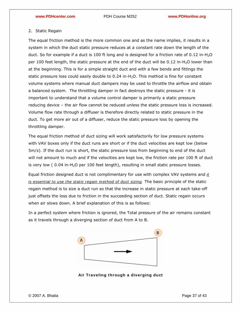
In a perfect system where friction is ignored, the Total pressure of the air remains constant
as it travels through a diverging section of duct from A to B.
Air Traveling through a diverging duct
www.PDHcenter.com PDH Course M252 www.PDHonline.org
© 2007 A. Bhatia Page 38 of 43
The Static Regain method of duct sizing is based on Bernoulli's equation, which states that
when a reduction of velocities takes place, a conversion of dynamic pressure into static
pressure occurs.
Now, Total Pressure = Static Pressure + Velocity Pressure
As the velocity, and therefore velocity pressure, reduces from point A to point B, the static
pressure must increase simultaneously to keep the total pressure constant. In real system
there is friction and this reduces the static regain by a factor, preventing a full recovery of
pressure. In practice this means that the air velocity is systematically reduced from the first
take-off or branch duct all the way to the last take-off. With this method, the air speed in
the duct is reduced near each branch or diffuser so that the dynamic pressure conversion
obtained exactly balances the pressure drop of the air in the trunk of the next duct. This
means there is the same static pressure near all the branches and all the diffusers, thereby
obtaining an intrinsically balanced air distribution system without having to use throttling
devices.
Under certain conditions, the static regain method produces some unexpected results
although there is a perfectly logical explanation for these. For example, if the take-offs are
far apart, the frictional pressure loss is relatively large and a duct size reduction may not be
required – the reduced flow rate after a take-off in the same size duct results in sufficient
slowing down of the air to produce the required static regain. In more extreme cases it may
actually be necessary to increase the duct size after take-off, so that the air velocity is
reduced sufficiently to provide the necessary regain.
One objection to the use of this method to size ducting is that it results in larger and more
expensive ducting. While this is true, the extent of the increase is often overestimated. The
weight of sheet metal required for a system designed by static regain is approximately 13%
more than the system designed by equal friction. However, the increase in first cost is offset
by reduced balancing time and operating cost. To put the size issue into perspective, the
following illustrates the relationship between air volume and duct size. Volume is
proportional to the square of the duct dimension i.e. to increase the volume of air carried in
a duct by 50%, a typical duct size would have to increase from 20x16 to 24x20. It is the
area that increases by 50%, not the duct dimensions. Similarly, significant reductions in air
velocity require only modest increases in duct size.
It may be advisable to apply two methods simultaneously; the constant pressure loss
method for sizing the main trunk, with insertion of adjustment air locks on the branches;
www.PDHcenter.com PDH Course M252 www.PDHonline.org
© 2007 A. Bhatia Page 39 of 43
the static pressure recovery method for sizing the branches fitted with terminals to obtain
the same operating pressure in the latter.
AHU FAN CONTROL WITH VARIABLE SPEED DRIVES (VSD)
A fan is designed to discharge a given capacity of air at a given horsepower. In a VAV
system, the amount of air needed depends on the needs of the space being served. Without
continuous feedback control, the fan will always deliver full capacity at full horsepower and
produce larger than necessary static pressures at the terminal units. Horsepower is wasted
and operational savings are not realized with improper control schemes. When a control
system is used to reset the fan capacity in accordance with the demands of the space,
excess static pressure at the terminal units is eliminated, and the fan system horsepower
adjusts to provide operational savings.
A variable-speed fan is the recommended approach to control duct air pressure in a VAV
system although several methods are possible. Variable-speed drives are the most efficient
and have the added advantage of limiting current inrush for startup of large motors (“soft-
start” feature). Other less effective duct pressure control devices are variable inlet vanes,
inlet cones, sliding covers, and discharge air dampers.
Fan Power Consumption
Basic fan laws state that the volume is directly proportional to speed; pressure is
proportional to the square of the speed; and the fan power is proportional to the cube of the
speed. Therefore, when the fan is slowed down by the use of a variable speed control
device, the total BHP requirements are reduced. There are four basic control techniques
used to vary the airflow rate; i) by system dampers on the outlet side of the fan, (ii) inlet
guide vanes on the fan (iii) eddy current coupling and (iv) variable speed control of the fan.
This last method provides the maximum energy efficiency, which is expressed as below:
HP2 = HP1 X (RPM2/RPM1)3
For example: A fan delivers 20,000 CFM against a total static pressure of 3.0 w.g. running
at 1,000 rpm. The power required at this condition is 15 BHP. If the fan speed were reduced
to 700 rpm the BHP would now be reduced to 5.1. By further reducing the fan speed to 500
rpm the required BHP would be 1.9. This assumes no loses in the drives at varying rpm
levels. As can be seen from this example, the use of variable speed control can offer
substantial savings in BHP at reduced speeds
OTHER FACTORS
www.PDHcenter.com PDH Course M252 www.PDHonline.org
© 2007 A. Bhatia Page 40 of 43
The code allows some VAV boxes serving a space to go to zero airflow, provided other boxes
serving that space are controlled to provide sufficient minimum ventilation for the entire
space. For example, a large open office plan might be served by two boxes, one in the
interior and one along the perimeter. Suppose the perimeter were 1000 ft2 and designed for
2000 CFM (2 CFM/ft2) while the interior was 1000 ft2 and designed for 500 CFM (0.5
CFM/ft2). The minimum airflow rate required for ventilation is 0.15 CFM/ft2 or 300 CFM.
Code could be met using a cooling-only box in the interior with a zero minimum airflow set-
point, and a reheat box serving the perimeter with a 15% (300 CFM) minimum set-point. If
the interior box is controlled to maintain its ventilation rate alone (equal to 30% of its
maximum), then a reheat coil would need to be added to this box to prevent overcooling
the space at minimum flow. Therefore, combining interior cooling-only boxes with perimeter
reheat boxes in open office plans saves first cost and energy. (This concept does not apply
when the interior and perimeter are separated from each other with full height partitions.)
Multiple zones serving a large zone - Another application where zero minimum airflow set
points allowed is for large zones (e.g., large meeting rooms) where more than one box may
be needed to meet the load. In this case, one or more of the boxes could have a zero
minimum, as long as at least one box has a non-zero minimum that can meet the minimum
ventilation requirements for the entire zone.
Number of VAV boxes - Designers traditionally selects zones by grouping adjacent rooms
that have similar cooling load profiles. If a zone contains private offices, it is possible that
up to eight offices can be served by one VAV box. The exact location of the box's controlling
temperature sensor is selected to reside in one of the spaces, often based on the status of
the office occupant.
A drawback to this particular strategy is that while the office with the sensor will maintain a
temperature close to the set-point, those offices without the sensor may not. Consequently,
the temperature or flow rate of air to the other spaces depends on the balancing dampers
serving each space. This problem can be resolved by increasing the number of VAV boxes
and local controls. In the example above, two VAV boxes, each serving four spaces, could
be installed to provide a smaller control zone and overall improved comfort level. But,
adding equipment can result in a higher cost.
Optimum Box Size
Most VAV-box manufacturers make boxes of the following sizes: 6 in., 7 in., 8 in., 9 in., 10
in., 12 in., 14 in., 16 in., and 24 in. by 16 in. While one might assume that life-cycle cost
(first cost, energy cost, etc.) would be optimized by including all of these sizes in a sizing
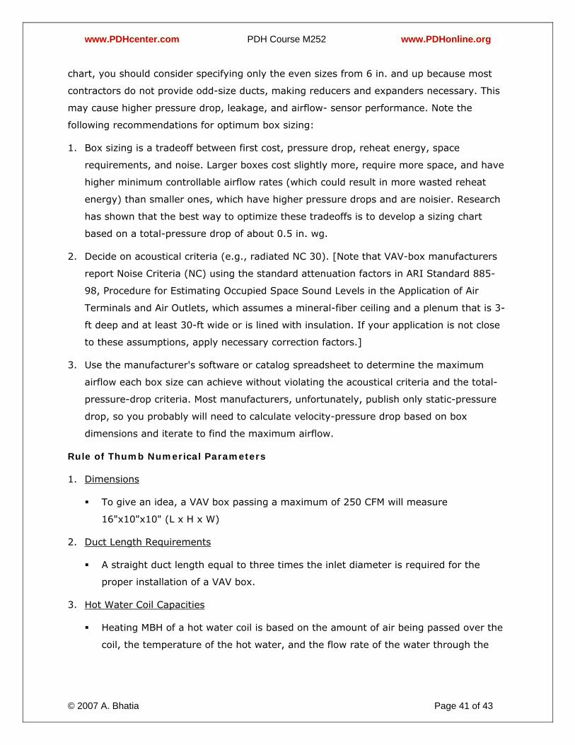
www.PDHcenter.com PDH Course M252 www.PDHonline.org
© 2007 A. Bhatia Page 41 of 43
chart, you should consider specifying only the even sizes from 6 in. and up because most
contractors do not provide odd-size ducts, making reducers and expanders necessary. This
may cause higher pressure drop, leakage, and airflow- sensor performance. Note the
following recommendations for optimum box sizing:
1. Box sizing is a tradeoff between first cost, pressure drop, reheat energy, space
requirements, and noise. Larger boxes cost slightly more, require more space, and have
higher minimum controllable airflow rates (which could result in more wasted reheat
energy) than smaller ones, which have higher pressure drops and are noisier. Research
has shown that the best way to optimize these tradeoffs is to develop a sizing chart
based on a total-pressure drop of about 0.5 in. wg.
2. Decide on acoustical criteria (e.g., radiated NC 30). [Note that VAV-box manufacturers
report Noise Criteria (NC) using the standard attenuation factors in ARI Standard 885-
98, Procedure for Estimating Occupied Space Sound Levels in the Application of Air
Terminals and Air Outlets, which assumes a mineral-fiber ceiling and a plenum that is 3-
ft deep and at least 30-ft wide or is lined with insulation. If your application is not close
to these assumptions, apply necessary correction factors.]
3. Use the manufacturer's software or catalog spreadsheet to determine the maximum
airflow each box size can achieve without violating the acoustical criteria and the total-
pressure-drop criteria. Most manufacturers, unfortunately, publish only static-pressure
drop, so you probably will need to calculate velocity-pressure drop based on box
dimensions and iterate to find the maximum airflow.
Rule of Thumb Numerical Parameters
1. Dimensions
To give an idea, a VAV box passing a maximum of 250 CFM will measure
16"x10"x10" (L x H x W)
2. Duct Length Requirements
A straight duct length equal to three times the inlet diameter is required for the
proper installation of a VAV box.
3. Hot Water Coil Capacities
Heating MBH of a hot water coil is based on the amount of air being passed over the
coil, the temperature of the hot water, and the flow rate of the water through the
www.PDHcenter.com PDH Course M252 www.PDHonline.org
© 2007 A. Bhatia Page 42 of 43
coil. For a 0.5 GPM flow rate serving a 75 CFM box, the heating capacity is 4.9 MBH.
For a 4.0 GPM flow rate serving a 500 CFM box, the heating capacity is 20 MBH.
4. Fan Motor Size
If choosing to add a fan to the VAV box, the horsepower of the fan motor depends on
the CFM of the box. For 250 CFM, a 1/6 horsepower motor is appropriate, while a 3/4
horsepower motor would be required to move 4200 CFM.
5. Fan Energy Savings with Variable Speed Drive on VAV AHU
Centrifugal fans are generally sized to handle the peak air volume requirements, which
typically occur for very short periods of time. Consequently, the equipment would be
operated at reduced volume most of the time. An energy comparison for 4 methods of
controlling fan airflow rate is tabulated below for a 100 HP fan motor. For this example,
the system would be operated for an average of 60% design CFM for 5000 hours
operation at $ 0.7 KWH.
6. Damper Position
The damper in a VAV box may close for a minimum setting of 15 to 20% of the
design volumetric flow rate. This may be required to ensure adequate ventilation in
the space.
Conclusion
Variable Air Volume technology is the most viable technology in today’s modern buildings
both for energy efficiency and performance. The VAV boxes can be preconfigured with
Building Automation System, which allows the facility manager to:
• Display all the zone temperatures in an area on a graphic
www.PDHcenter.com PDH Course M252 www.PDHonline.org
© 2007 A. Bhatia Page 43 of 43
• Adjust the individual set-points of zones from a central location
• Maintain historical records of zone temperature values.
A good understanding of the Variable Air Volume (VAV) systems is essential for HVAC
designer to meet the needs of current fast track projects and at the same time ensure that
the building gets the environmental system that will best fit its needs.
**************