hw 1)983 b mining u,wv - search geologyontario · l m 9 3-1 l 3. aircraft equipment 3.1 aircraft l...
TRANSCRIPT

REPORT ON
COMBINED HELICOPTER-BORNE
MAGNETIC, ELECTROMAGNETIC,
AND VLF-EM SURVEY
ON
LIZAR CLAIM GROUP
ll 42CI6NWeie6 2.5970 LIZAR 010
l
l
l
l
l
l
l
l
l HW 1)983
B MINING u,wv .
l
l
l
l
l
l
for
TUNDRA GOLD MINES LIMITED
by
AERODAT LIMITED
July 1983

1111111111111111111
*2ci6Nwei06 2.5970 LIZARff\ |\ T"* T
1. INTRODUCTION
2. SURVEY AREA/CLAIM NUMBERS AND LOCATIONS
3. AIRCRAFT EQUIPMENT
3.1 Aircraft
3 . 2 Equipment
3.2.1 Electromagnetic System
3.2.2 VLF-EM
3.2.3 Magnetometer
3.2.4 Magnetic Base Station
3.2.5 Radar Altimeter
3.2.6 Tracking Camera
3.2.7 Analog Recorder
3.2.8 Digital Recorder
4. DATA PRESENTATION
4.1 Base Map and Flight Path Recovery
4.2 Electromagnetic Profile Maps
4 . 3 Magnetic Contour Maps
4.4 VLF-EM Contour Maps
4.5 Electromagnetic Survey ConductorSymbolization
4.6 Interpretation Maps
APPENDIX I - General InterpretiveConsiderations
1Page
1 -
2 -
3 -
3 -
3 -
3 -
3-
3 -
3 -
3 -
3 -
3 -
3 -
4 -
4 -
4 -
4 -
4 -
4 -
4 -
01
NO.
1
1
l
1
1
1
1
2
2
2
3
3
4
1
1
2
4
5
6
8

LIST OF MAPS
l(Scale: 1/15,840)
l
Map l Interpreted Conductive Unitsl
I Map 2 Airborne Electromagnetic Survey Profile Map (955 Hz. coaxial)
m Map 3 Total Field Magnetic Map
Map 4 VLF-EM Total Field Contours
l
lm Data provided but not included in report:
l l - master map (2 colour) of coaxial andcoplanar profiles with flight path
1 2 - anomaly list providing estimates of deoth and conductivitv thickness
M 3 - analogue records of data obtained in
depth and conductivity thickness
analog flight
l
l
l
l
l
l
l

1. INTRODUCTION
lll
l This report describes an airborne geophysical survey
m carried out on behalf of Tundra Gold Mines Limited by
Aerodat Limited. Equipment operated included a 3
l frequency electromagnetic system, a VLF-EM system, and
a magnetometer.
The survey was flown on March 26 to March 29, 1983
l from an operations base at Wawa Ontario. A total of
541 line miles were flown, at a nominal line spacing of
660 feet. Of the total flown, this report describes
l 334.4 line miles.
l
l
l
l
l
l
l
l
l

2-1
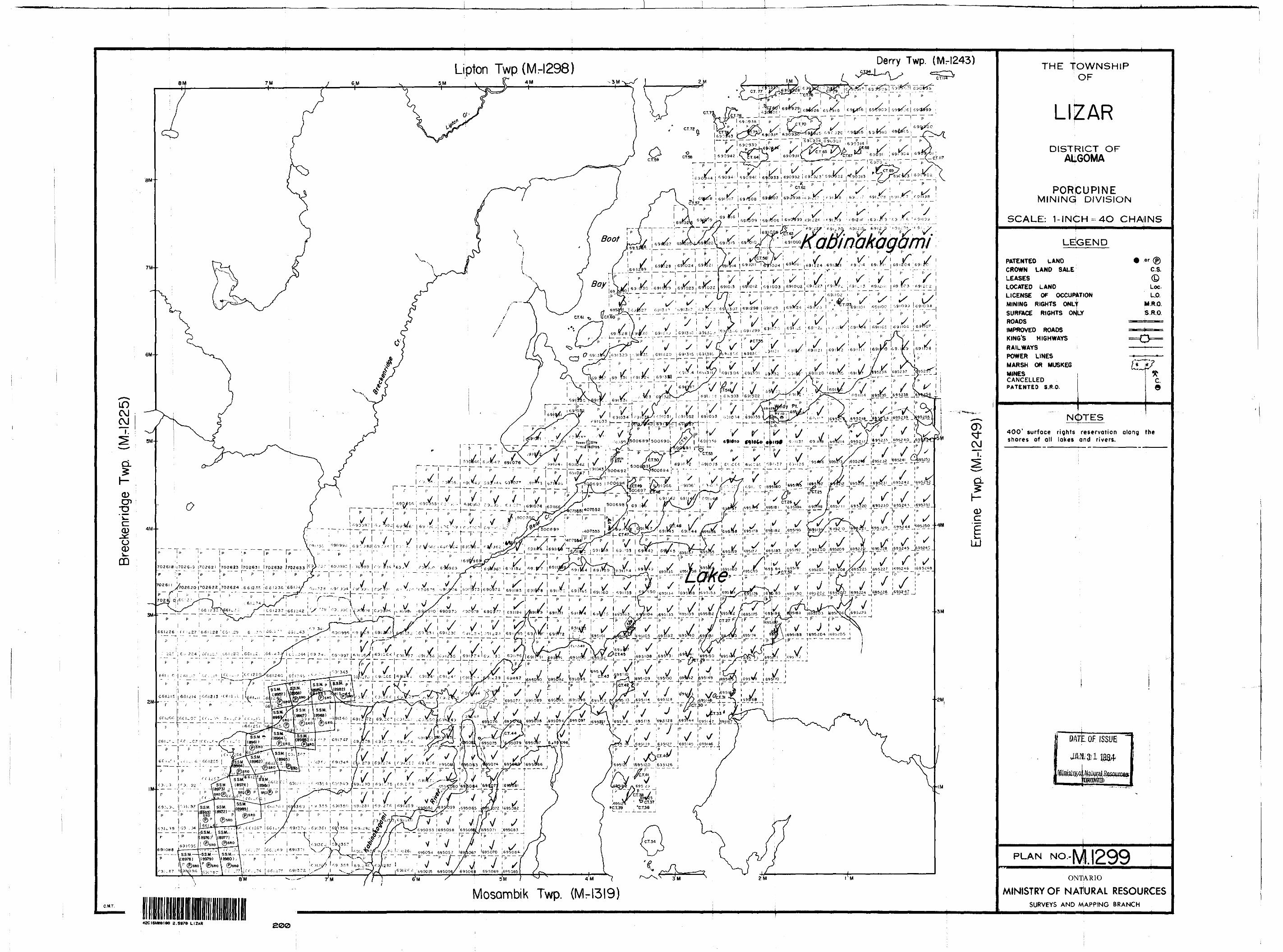
The mining claim numbers and locations covered by this
survey are indicated on the map in the following pocket.
l lI 2. SURVEY AREA/CLAIM NUMBERS AND LOCATIONS
l
l
l
l
l
l
l
l
l
l
l
l
l
l
l
l

lm 9 3-1
l 3. AIRCRAFT EQUIPMENT
3.1 Aircraft
l The helicopter used for the survey was an Aerospatial
H Astar 350D owned and operated by North Star Helicopters.
Installation of the geophysical and ancillary equipment
l was carried out by Aerodat. The survey aircraft was
flown at a nominal altitude at 60 meters.
3.2 Equipment
3.2.1 Electromagnetic System
The electromagnetic system was an Aerodat/
M Geonics 3 frequency system. Two vertical
coaxial coil pairs were operated at 955 and
g 4130 Hz and a horizontal coplanar coil pair
at 4500 Hz. The transmitter-receiver separa-
' tion was 7 meters. In-phase and quadrature
l signals were measured simultaneously for the
3 frequencies with a time-constant of 0.1
g seconds. The electromagnetic bird was towed
30 meters below the helicopter.
3.2.2 VLF-EM System
The VLF-EM System was a Herz 2A. This instru-
J ment measures the total field and vertical
l
l
l
m
3-2
quadrature component of two selected frequencies.
The sensor was towed in a bird 15 meters below
the helicopter.
The sensor aligned with the flight direction
l is designated as "LINE" , and the sensor
perpendicular to the line direction as "ORTHO" .
J The "LINE" station used was NAA, Cutler Maine,
- 17.8 KHz or NLK, Jim Creek Washington, 24.8 KHz.
The "ORTHO" station was NSS, Annapolis Maryland,
M 21.4 KHz. The NSS transmitter was operating on
a very limited schedule and was not available
j during a large part of the survey.
l 3.2.3 Magnetometer
l The magnetometer was a Geometrics G-803 proton
precession type. The sensitivity of the
J instrument was l gamma at a 1.0 second sample
rate. The sensor was towed in a bird 15 meters
" below the helicopter.
l 3.2.4 Magnetic Base Station
J An IFG proton precession type magnetometer was
operated at the base of operations to record
diurnal variations of the earths magnetic
field. The clock of the base station was
synchronized with that of the airborne system

3-3
ll *l to facilitate later correlation.
l 3.2.5 Radar Altimeter
l A Hoffman HRA-100 radar altimeter was used to
record terrain clearance. The output from the
J instrument is a linear function of altitude
for maximum accuracy.
3.2.6 Tracking Camera
A Geocam tracking camera was used to record
J flight path on 35 mm film. The camera was
operated in strip mode and the fiducial numbers
" for cross reference to the analog and digital
l data were imprinted on the margin of the film.
m 3.2.7 Analog Recorder
A RMS dot-matrix recorder was used to display
" the data during the survey. A sample record
l with channel identification and scales is
presented on the following page.
l
l
l
l
l

ANALOG CHART
CAMERA ^FIDUCIAL
VLF TOTAL
COPLANAR QUA04.
50 gammas
COPLANAR. Iljr PHASER ^
40 ppm.
COAXIAL IJj-PHASsE(HIGH FREQv)
l l l l l
COAXIAL JAD
(LOW FREQ.)^ t
/v20 ppm.
COAXIAL^, IN-PHASE{LOW FREQ.) 20 ppm.
-CLr m:; MMI
"^MANUAL FIDUCIAL

l l l l l l l l l l l l l l l l l l l
3-4
3.2.8 Digital Recorder
A Perle DAC/NAV data system recorded the survey
data on cassette magnetic tape. Information
recorded was as follows:
Equipment
EM
VLF-EM
magnetometer
altimeter
fiducial (time)
fiducial (manual)
Interval
0.1 second
0.5 second
0.5 second
1.0 second
1.0 second
O.2 second

l
l
l
l
l
l
l
l
l
l
l
4-1
4. DATA PRESENTATION
l l l 4.1 Base Map and Flight Path Recovery
l The base map photomosaic at a scale of 1/15,840 was
m constructed from available aerial photography. The
flight path was plotted manually on this base and
l digitized for use in the computer compilation of the
maps. The flight path is presented with fiducials
for cross reference to both the analog and digital
data.

l l l
l
4-2
4.2 Electromagnetic Profile Maps
l The electromagnetic data was recorded digitally at
a high sample rate of 10/second with a small time
m constant of 0.1 second. A two stage digital filtering
m process was carried out to reject major sferic events,
and reduce system noise.
Local atmospheric activity can produce sharp, large
l amplitude events that cannot be removed by conventional
filtering procedures. Smoothing or stacking will reduce
l their amplitude but leave a broader residual response
H that can be confused with a geological phenomenon. To
avoid this possibility, a computer algorithm searches
out and rejects the major "sferic" events.
The signal to noise was further enhanced by thelapplication of a low pass filter. The filter was
l applied digitally. It has zero phase shift which
prevents any lag or peak displacement from occurring
and it suppresses only variation with a wavelength
B less than about 0.25 seconds. This low effective time
constant permits maximum profile shape resolution.
Following the filtering processes, a base level
l correction was made. The correction applied is a linear
function of time that ensures that the corrected
l amplitude of the various inphase and quadrature components
l

l l
l l
l
l
l
l
l
l
l
l
l
l
4-3
is zero when no conductive or permeable source is
present. This filtered and levelled data was then
presented in profile map form.
The in-phase arid quadrature responses of the coaxial
955 Hz configuration are plotted with the flight
path and presented on the photomosaic base.
The in-phase and quadrature responses of the coaxial
l 4500 Hz and the coplanar 4130 Hz configuration are
plotted with flight path and are available as a two
colour overlay.

l l l
4-4
4.3 Magnetic Contour Maps
l The aeromagnetic data was corrected for diurnal
variations by subtraction of the digitally recorded
i base station magnetic profile. No correction for
H regional variation is applied.
m The corrected profile data was interpolated onto a
regular grid at a 2.5 nun interval using a cubic
l spline technique. The grid provided the basis for
threading the presented contours at a 10 gamma
l interval.
l
l
l
l
l
l
l
l
l
l

4-5
l ll 4.4 VLF-EM Contour and Profile Maps
l The VLF-EM "LINE" signal, was compiled in map form.
The mean response level of the total field signal
l was removed and the data was gridded and contoured
m at an interval of 21. When the "ORTHO" signal was
available it was compiled in a similar fashion.
l
l
l
l
l
l
l
l
l
l
l
l
l

lm 9 4-6
l 4.5 Electromagnetic Conductor Symbolization
l The electromagnetic profile maps were used to
identify those anomalies with characteristics
l typical of bedrock conductors. The in-phase
mm and quadrature response amplitudes at 4130 Hz
were digitally applied to a phasor diagram for
l the vertical half-plane model and estimates of
conductance (conductivity thickness) were made.
l The conductance levels were divided into categories
mm as indicated in the map legend; the higher the number,
the higher the estimated conductivity thickness
l product.
U As discussed in Appendix I the conductance should be
used as a relative rather than absolute guide to
m conductor quality. A conductance value of less than
2 mhos is typical for conductive overburden material
" and electrolytic conductors in faults and shears.
B Values greater than 4 mhos generally indicate some
electronic conduction by certain metallic sulphides
l and/or graphite. Gold, although highly conductive,
is not expected to occur in sufficient concentration
l
l
l
to directly produce an electromagnetic anomaly;
however, accessory mineralization such as pyrite or

l l l
4-7
graphite can produce a measurable response.
l With the aid of the profile maps, responses of similar
characteristics may be followed from line to line and
m conductor axes identified.
J The distinction between conductive bedrock and over-
burden anomalies is not always clear and some of
the symbolized anomalies may not be of bedrock origin.
l It is also possible that a response may have been
mistakenly attributed to overburden and therefore not
l included in the symbolization process. For this reason,
B as geological and other geophysical information becomes
available, reassessment of the significance of the
l various conductors is recommended.
l
l
l
l
l
l
l
l

11 *
1111111111111
" 4-8
4.6 INTERPRETATION MAPS
The conductive trends are shown and discriminated
for descriptive purposes.
These conductors are described below.
1 Questionable, probably overburden,
to diabase dyke.
2 Moderate, deep conductor on flank
magnetic trend.
next
of
3 Poor conductivity on flank of magnetic
response .
4 Conductive lake sediments probably
this response.
cause
5 Possible bedrock response below lake
sediments.
6 Questionable, probably overburden
7 Low amplitude response on flank of
high.
R Possible mnltinle below lake serJim
magne
en'hs
on flank of magnetic high.

l l l l l l l l l l l l l l l l l l l
10
11
12
13
14
15
16
17
August 8, 1983.
4-9
Questionable response next to diabase
dyke.
Weak conductor coinciding with magnetic
high. On trend from gold prospect.
Possible conductor below lake sediments
Possible conductor below lake sediments
Possible conductor on south flank of
magnetic high.
Possible conductivity below lake sediments
with coincident magnetic high.
Probable weak conductor coincides with
crest of long magnetic feature.
Possible multiple conductors bracketting
magnetic high.
Possible bedrock conductor under conductive
sediments.
Respectfully submitted,
Fenton Scott, P.Eng.

APPENDIX I
GENERAL INTERPRETIVE CONSIDERATIONS
l l l Electromagnetic
l The Aerodat 3 frequency system utilizes 2 different
m transmitter-receiver coil geometries. The traditional
coaxial coil configuration is operated at 2 widely
l separated frequencies and the horizontal coplanar coil
pair is operated at a frequency approximately aligned
with one of the coaxial frequencies.
l The electromagnetic response measured by the helicopter
m system is a function of the "electrical" and "geometrical"
properties of the conductor. The "electrical" property
l of a conductor is determined largely by its conductivity
and its size and shape; the "geometrical" property of the
B response is largely a function of the conductors shape and
B orientation with respect to the measuring transmitter and
receiver.
lElectrical Considerations
lFor a given conductive body the measure of its conductivity
l or conductance is closely related to the measured phase
shift between the received and transmitted electromagnetic
H field. A small phase shift indicates a relatively high
l conductance r a large phase shift lower conductance. A
small phase shift results in a large in-phase to quadrature
l

lm 9 - 2 - APPENDIX I
l ratio and a large phase shift a low ratio. This relation
ship is shown quantitatively for a vertical half-plane
m model on the accompanying phasor diagram. Other physical
B models will show the same trend but different quantitative
relationships.
The phasor diagram for the vertical half-plane model, as
l presented, is for the coaxial coil configuration with the
amplitudes in ppm as measured at the response peak over
B the conductor. To assist the interpretation of the survey
M results the computer is used to identify the apparent
conductance and depth at selected anomalies. The results
J of this calculation are presented in table form in Appendix I
and the conductance and in-phase amplitude are presented
" in symbolized form on the map presentation.
l
l
The conductance and depth values as presented are correct
only as far as the model approximates the real geological
situation. The actual geological source may be of limited
l length, have significant dip, its conductivity and thickness
may vary with depth and/or strike and adjacent bodies and
B overburden may have modified the response. In general the
B conductance estimate is less affected by these limitations
than the depth estimate but both should be considered a
J relative rather than absolute guide to the anomalies
properties.

l l l l l l l l l l l l l l l l l l l
- 3 - APPENDIX I
Conductance in mhos is the reciprocal of resistance in
ohms and in the case of narrow slab like bodies is the
product of electrical conductivity and thickness.
Most overburden will have an indicated conductance of less
than 2 mhos; however, more conductive clays may have an
apparent conductance of say 2 to 4 mhos. Also in the low
conductance range will be electrolytic conductors in faults
and shears.
The higher ranges of conductance, greater than 4 mhos,
indicate that a significant fraction of the electrical
conduction is electronic rather than electrolytic in nature.
Materials that conduct electronically are limited to certain
metallic sulphides and to graphite. High conductance
anomalies, roughly 10 mhos or greater are generally limited
to sulphide or graphite bearing rocks.
Sulphide minerals with the exception of sphalerite, cinnabar
and stibnite are good conductors; however, they may occur
in a disseminated manner that inhibits electrical conduction
through the rock mass. In this case the apparent conductance
can seriously under rate the quality of the conductor in
geological terms. In a similar sense the relatively non
conducting sulphide minerals noted above may be present in
significant concentration in association with minor conductive

l- 4 - APPENDIX I
sulphides, and the electromagnetic response only relate
to the minor associate mineralization. Indicated conductance
is also of little direct significance for the identification
of gold mineralization. Although gold is highly conductive
it would not be expected to exist in sufficient quantity
to create a recognizable anomaly but minor accessory sulphide
mineralization could provide a useful indirect indication.
In summary the estimated conductance of a conductor can
provide a relatively positive identification of significant
sulphide or graphite mineralization; however^ a moderate
to low conductance value does not rule out the possibility
of significant economic mineralization.
Geometrical Considerations
Geometrical information about the geologic conductor can
often be interpreted from the profile shape of the anomaly.
The change in shape is primarily related to the change in
inductive coupling among the transmitter, the target, and
the receiver.
In the case of a thin, steeply dipping, sheet-like conductor,
the coaxial coil pair will yield a near symmetric peak over
the conductor. On the other hand the coplanar coil pair will
pass through a null couple relationship and yield a minimum
over the conductor, flanked by positive side lobes. As the
dip of the conductor decreases from vertical, the coaxial

lM ^ - 5 - APPENDIX I
l anomaly shape changes only slightly, but in the case of
the coplanar coil pair the side lobe on the down dip side
l strengthens relative to that on the up dip side.
J As the thickness of the conductor increases, induced
current flow across the thickness of the conductor becomes
B relatively significant and complete null coupling with the
l coplanar coils is no longer possible. As a result, the
apparent minimum of the coplanar response over the conductor
l diminishes with increasing thickness, and in the limiting
m case of a fully 3 dimensional body or a horizontal layer
or half -space, the minimum disappears completely.
A horizontal conducting layer such as overburden will produce
l a response in the coaxial and coplanar coils that is a
function of altitude (and conductivity if not uniform) . The
l profile shape will be similar in both coil configurations
g with an amplitude ratio (coplanar/coaxial) of about 4/1.
In the case of a spherical conductor, the induced currents
m are confined to the volume of the sphere, but not relatively
l restricted to any arbitrary plane as in the case of a sheet-
l
l
like form. The response of the coplanar coil pair directly*
over the sphere may be up to 8 times greater than that of
the coaxial coil pair.

l l - 6 - APPENDIX I
l In summary a steeply dipping, sheet-like conductor will
display a decrease in the coplanar response coincident
l with the peak of the coaxial response. The relative
m strength of this coplanar null is related inversely to
the thickness of the conductor? a pronounced null indicates
l a relatively thin conductor. The dip of such a conductor
can be infered from the relative amplitudes of the side-lobes,
Massive conductors that could be approximated by a conducting
l sphere will display a simple single peak profile form on both
M coaxial and coplanar coils, with a ratio between the coplanar
to coaxial response amplitudes as high as 8.*
Overburden anomalies often produce broad poorly defined
l anomaly profiles. In most cases the response of the coplanar
coils closely follow that of the coaxial coils with a
J relative amplitude ratio of 4.*
l Occasionally if the edge of an overburden zone is sharply
defined with some significant depth extent, an edge effect
l will occur in the coaxial coils. In the case of a horizontal
m conductive ring or ribbon, the coaxial response will consist
of two peaks, one over each edge; whereas the coplanar coil
l will yield a single peak.
l
l
l

l lll l l l l l l l l l l l l l l l
- 7 - APPENDIX I
* It should be noted at this point that Aerodat's definition
of the measured ppm unit is related to the primary field
sensed in the receiving coil without normalization to the
maximum coupled (coaxial configuration). If such normal
ization were applied to the Aerodat units, the amplitude
of the coplanar coil pair would be halved.

l l l l l l l l l l l l l l l l l l l
- 8 - APPENDIX J
Magnetics
The Total Field Magnetic Map shows contours of the
total magnetic field, uncorrected for regional varia
tion. Whether an EM anomaly with a magnetic correla
tion is more likely to be caused by a sulphide deposit
than one without depends on the type of mineralization.
An apparent coincidence between an EM and a magnetic
anomaly may be caused by a conductor which is also
magnetic, or by a conductor which lies in close proximity
to a magnetic body. The majority of conductors which are
also magnetic are sulphides containing pyrrhotite and/or
magnetite. Conductive and magnetic bodies in close
association can be, and often are, graphite and magnetite.
It is often very difficult to distinguish between these
cases. If the conductor is also magnetic, it will usually
produce an EM anomaly whose general pattern resembles
that of the magnetics. Depending on the magnetic perme
ability of the conducting body, the amplitude of the
inphase EM anomaly will be weakened, and if the conduc
tivity is also weak, the inphase EM anomaly may even be
reversed in sign.

lg W - 9 - APPENDIX I
l VLF Electromagnetics
l The VLF-EM method employs the radiation from powerful
military radio transmitters as the primary signals.
g The magnetic field associated with the primary field
g is elliptically polarized in the vicinity of electrical
conductors. The Herz Totem uses three coils in the X.
l Y. Z. configuration to measure the total field and
vertical quadrature component of the polarization
l ellipse.
l The relatively high frequency of VLF 15-25 KHz provides
g high response factors for bodies of low conductance.
" Relatively "disconnected" sulphide ores have been found
l to produce measurable VLF signals. For the same reason,
poor conductors such as sheared contacts, breccia zones,
l narrow faults, alteration zones and porous flow tops normally
m produce VLF anomalies. The method can therefore be used
effectively for geological mapping. The only relative dis-
I advantage of the method lies in its sensitivity to conductive
overburden. In conductive ground the depth of exploration
l is severely limited.
g The effect of strike direction is important in the sense
p of the relation of the conductor axis relative to the
energizing electromagnetic field. A conductor aligned
8 along a radius drawn from a transmitting station will be
l

lI - 10 - APPENDIX I
B in a maximum coupled orientation and thereby produce a
stronger response than a similar conductor at a different
m strike angle. Theoretically it would be possible for a
B conductor, oriented tangentially to the transmitter to
produce no signal. The most obvious effect of the strike
B angle consideration is that conductors favourably oriented
with respect to the transmitter location and also near
perpendicular to the flight direction are most clearly
8 rendered and usually dominate the map presentation.
B The total field response is an indicator of the existence
and position of a conductivity anomaly. The response will
J be a maximum over the conductor, without any special filtering,
and strongly favour the upper edge of the conductor even in
the case of a relatively shallow dip.
8 The vertical quadrature component over steeply dipping sheet
m like conductor will be a cross-over type response with the
cross-over closely associated with the upper edge of the
l conductor.
B The response is a cross-over type due to the fact that it
is the vertical rather than total field quadrature component
l that is measured. The response shape is due largely to
m geometrical rather than conductivity considerations and
the distance between the maximum and minimum on either side
l of the cross-over is related to target depth. For a given
target geometry, the larger this distance the greater the

lm W - 11 - APPENDIX I
B depth.
m The amplitude of the quadrature response, as opposed
to shape is function of target conductance and depth
J as well as the conductivity of the overburden and host
* rock. As the primary field travels down to the conductor
" through conductive material it is both attenuated and
l phase shifted in a negative sense. The secondary field
produced by this altered field at the target also has an
l associated phase shift. This phase shift is positive and
g is larger for relatively poor conductors. This secondary
field is attenuated and phase shifted in a negative sense
l during return travel to the surface. The net effect of
these 3 phase shifts determine the phase of the secondary
l field sensed at the receiver.
l A relatively poor conductor in resistive ground will yield
g a net positive phase shift. A relatively good conductor
* in more conductive ground will yield a net negative phase
l shift. A combination is possible whereby the net phase
shift is zero and the response is purely in-phase with no
l quadrature component.
J A net positive phase shift combined with the geometrical
cross-over shape will lead to a positive quadrature response
* on the side of approach and a negative on the side of
l departure. A net negative phase shift would produce the
reverse. A further sign reversal occurs with a 180 degree
l

l - 12 - APPENDIX I
m change in instrument orientation as occurs on reciprocal
line headings. During digital processing of the quad-
I rature data for map presentation this is corrected for
by normalizing the sign to one of the flight line headings,
l
l
l
l
l
l
l
l
l
l
l
l
l
l

Ministryof Report of Work'SSitxt (Geophysical, Geological,
Ontario J** ^. .Gepf^gmipal and Expenditures)42C16NW8106 2.597e LIZAR 300
Mining An f v*w *" ' * ** l - DO not use shaded areas below.
TtAiVDM Li H IT EnAddress
Prospector's Licence No.
77533
Survey CompanyINDIAN Mf.*
Date of Survey (from 81 to)/tev/tey/ae?
Total Miles oHina Cut V\'-••iName and Address Df Author (of Geo-TechnicaPfeportf
/y rts\L^\RAR. PLCredits Requested per Each Claim in Columns at right Mining Claims Traversed (List in numerical sequence)
.--- "- - - ~ ,. Total ,.. ' Days CreditsTotal Expenditures
fi i- -i. ; i 39311) C B H {3"} rTptil number of mlhipg . Vv ' i - i - ., ..claims covered by this
Instructions "' . . .Total Days Credits may ba apportioned at the claim holder's choice. Enter number of days credits per claim selected in columns at right. ' ]
Certification Verifying Rep6rt of Workl hereby certify that l have a personal and intimate knowledge of the facts set forth in the Report of Work annexeo^iapno,' having performed the work or witnessed same during and/or after its completion and the annexed report is true. ••••**m*t**M~**-i
Name and Postal Address of Person Certifying

M.
V

MirvslryotNaturalResources
Ontario
Report of Work(Geophysical, Geological, Geochemical and Expenditures) 9Hi
The Mining Act
ructions: Please type or print., If number of mining claims traversed
exceeds space on this form, attach a list.Note: Only days credits calculated in the
"Expenditures" section may be enteredin the "Expend. Days Cr." columns.
IHIII ^r^^Qo not use shaded, prf-1 ypo of Survey(s)
, VLFTownship or Area
Ll-z^vfL .Holcier(s)
1LTO,Prospector's Licence"!
T r
, MSurvey Company
r ut M \ -Name and Address of Author (of Geo-T echmcal report)
Date of Survey (from fi* to)
"26. 3 5J3 1^ 3 83Day j Mo. t Yr. Day | Mo. j Yr.
lota! Miles of line Cut
33-4 . 4.
pl-?
Credits Requested per Each Claim in Columns at right Mining Claims Traversed (List in numerical sequence)
Sr*:iai Provisions Geophysical ! D^,^e '
For first survey: r , , - ElectromagneticEnter 40 days. (This L. .. ... .includes line cutting) . -Magnetometer
l
For each additional survey: -Radiometric
usma the same qrid: , - Other
Enter 20 days (for each)
Geolop cal
i Geoc hemical i
MB " Days ,. , Days i,i- Geophysical Cia""
Complete reverse side ,, . . Elecirornaqne* ic
and enter totalis) here ;
- Magnetometer
; - Radiometric
- Other
1 Geolog cal
Geocherrncal
Ai':.io'.-ic Creriits ' Days per
Note: Special provisions Electromagnetic 2.1-^
cicd.ts do not apply . . . -.
WnlJ^T?^^7 VP" fWOPhParfo|^. 1031993^ 1^"^S^^^-C-fSif u)at;on of Expenditure Days Credits
Total Total Expenditures Days Credits
|S -:- 15 --
.nstruclions
Mining Clairri
Prefix, Number
x?"5 i
: Li S"* A1 T
E xpencl.Days Cr.
T, f^~
kf-HGK
Mi
/: A
Mining ClaimPref ix : Number
1
. , ' ' -t - t ' ,' ) "'
;, l./.i.;.;.. .,.i. i.. '
" Cl ••"^yrj
Expend. Days Cr.
-
-..----.
--.-~ -
- --
..--..-
Total numr-er of mining claims covered Py this 6(^3" report of work.
Totel Days Credits may ho apportioned at the claim holder's choice. Enter number of days credits per ciairn selected iri col'j rnns at j ight.
- For Office Use OnlyTotai Days Ciliate Reechoed
l-:iti j Recorded Holder o r Ape n,;^ S i ci nature)
ii^*T *^t t s 6* "t. l f \ ^f ^f^^^-^'' —^^ lLx*-- *- *- x l X Jv O IX JJ^Xx??x x^"5'C-— ---.-— -_ I
C-?t tifiCcition^yerifyinc) Report of Work
1 hjrehy certify that 1 have a personal end intimate knowledge of thr facts so; forth m the Report of Work annexed hereto, having performed the work or w-tnesseci same during and/or after its completion and the annexed leport is true.
|\3rno and Postal Auclress of Person Certifying
jD.itc C.C'ftifit;; [Cf'liUrd py IS onatuf^i ! ' v y X /"

..........?.2/.691 o jpo/
_..^...-.o!../!-- .——
.si64
y.1.1. .!.l
..tft.i, /i i y
JA /3 J S
.0.4.os- 1' rsi/0^ ^ 5"4-^
o-i j Si"7-.. - .....fc.*Lv....-..-.- . — — . - - -^-^ — -— .
^5iTv/ 53 ^ oy" ^*3^ t/ 54^ ^ ^O7 i/ 56"/ ^7 ^
oi^^ ^4.^ 02 ^
lo X
J S".14...
It,,.n... ^ je-.-^- .1.3... v..9
68,
7011
24 j/
-22
3.1.. .V.
7 S"
..77...
2.7
30
.31 t
34. y,-3.VT..-'.....3C..V.. 37 J
82 8.3..
^
79 y--31, y33V
e^ yS7. /..eg... y.
41
43 i/.44 y
A* -/

T .144—^—3*.5-4 v/
S3
~J
.......43 J... ... .5-0 y
sz /
^2-/ 4g^ 01.^ fi.^ 04^
o3 ^ *9 y 0)5lX 51 y *55- ^04 ^ 5"6v/ oA v/ 5Tg J Qf, J
^S" ^ . .. .. ..S"J ^ - O^v/ c-ft v ,o7 ^
AU. II63
10 lo Mli-
13
"^ y s / •/..O..J. )3
K
V.. Jy
;;;7/-77 i/
-1.V
43 v-"^"-'-J ~-
IL */j^-J tj t ^, , 1 7 v x 6 7 */
...... ..1.8..^............. i 4 ^
it* J - 7i yX 17 ^ 7Z ^
lg v/ 73 J
(V '19 ^
2*5 ^
7-1
6?
71 .73.
'
74-y.7*: y
77 V TO S V'
53 y, w. /..
v/
7
/,.
74V
61 7
3o 3J
i.4;. 3J"
.7.3-^..
ei V
i/
.33.
V-ffi; ^o; y..41....^.
4?* V
91
r:/"It
3^

...T..6.9^.i4.i.v:.4.7- 46
?
3 C.
o ^ ^? ^yv v/ ?t J
""" "v ^7.............sv: ^.-............-6/:/....
43 v/ 6 ^ v"34-fiTy44 V/ 4-^. i/
^V ' "" ^tj .-......-...-..-.-..-.-.--..
41 v/*V ^ 65V3S3 J
.44. l/ li/ K
Si*.
V T*-
7 y
..-LI ...^11. v'
it.
to w'
10.. J '
— C. \4-
06; V
is- y•Li* J i7 Jlg J ?-i y
^t J
•3}
..v"
37

© Ministry of Natural Refjj^es
Ontario ^^B
Geotechnical Fileo Report of- ^ r ~? OApproval
Mining Lands Comments
D
D
To: Geophysics /•'i \^ - i 's-' . : .-M 'Comments
[^fTfpproved Q Wish to see again with corrections ""jy , 7/}?^? ^^"^ Lt^ J&*— )
//To: Geology - Expenditures (S
Comments
- ------- - —————
j [ ApprovedDate Signature
| | Wish to see again with corrections
To: Geochemistry
Comments
| ] Approved
To: Mining Lands
- — -— ------ - ———
Date Signature | | Wish to see again with corrections
Section, Room 6462, Whitney Block. {Tel: 5-1380)

1983 11 08 2.5970
Mining RecorderMinistry of Natural Resources60 Wilson AvenueTimmins, OntarioP4N 2S7
Dear Sir:
We have received reports and maps for an Airborne Geophysical {tiectromagnetlc and Magnetometer and VLF) survey submitted on mining claims P 690898 et al 1n the Townships of Lizar, Ermine and Derry.
This material will be examined and assessed and a statement of assessment work credits will be Issued.
We do not have a copy of the report of work which 1s normally filed with you prior to the submission of this technical data. Please forward a copy as soon as possible.
Yours very truly,
I.r. AndersonDirectorLand Management Branch
Whitney Block, Room 6643 Queen's Park Toronto, Ontario M7A 1W3 Phone:(416)965-1380
A. Barr:me
cc: Tundra Gold Mines Limited c/o H.I. Miller Suite 120545 Richmond Street West Toronto, Ontario M5H 1Z2
cc: Fenton Scott 17 Malabar Place Don Mills, OntarioM3B 1A4

Ontario
Ministry of Natural Resources
GEOPHYSICAL - GEOLOGICAL - GEOCHEMICAL TECHNICAL DATA STATEMENT
File.
TO BE ATTACHED AS AN APPENDIX TO TECHNICAL REPORTFACTS SHOWN HERE NEED NOT BE REPEATED IN REPORT
TECHNICAL REPORT MUST CONTAIN INTERPRETATION, CONCLUSIONS ETC.
y,o a
w u
O
Airborne ttloctroifiagnetic, Magnetic,Type ofTownship or Arca Li aar, .Krminc, DerryClaim Holdcr( s) Tundra Gold MJncs Id ml ted
Survey Company —
Author of Report -
Address of Author.
Acrodat "jd.rnjtedFenton Scott
V KaJabar } 'li ac e, Don Kills, On t.
Covering Dates of Survey-
Total Miles of Line Cut M
'arch 26 to 29, 1983((incoming to office)
SPECIAL PROVISIONS CREDITS REQUESTED
ENTER 40 days (includes line cutting) for first survey.
ENTER 20 days for each additional survey using same grid.
Geophysical
-Electromagnetic.
-Magnetometer-—
-Radiometric——-Other——.————
DAYSper claim
Geological.
Geochemical.
AIRBORNE CREDITS (Special provision credits do not apply to airborne turveyi)^T,, t - 21 .8 .aJILF^. 21.8 __Electromagnetic _____Kadiomctric-—————, . Magnetometer
(enter days per claim)
HATE;. October 31 /83Kir,NATiiRttr"~Author of Report or Agent
Res. Geol..— ________Qualifications _^1^'—Previous Surveys
File No. Type Date Claim Holder
MINING CLAIMS TRAVERSED List numerically
P 690898 et al(prefix) (number)see list attached
TOTAL CLAIMS.
837 (5/79)
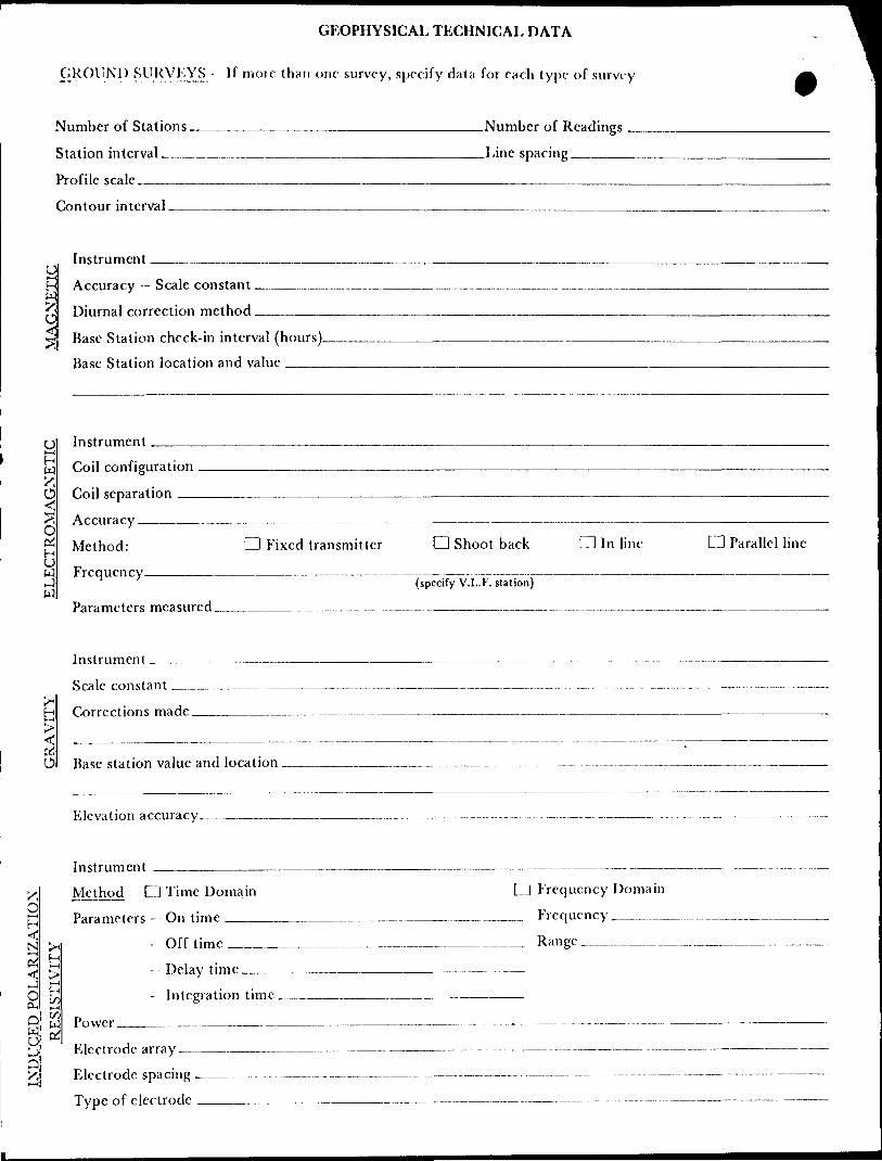
GEOPHYSICAL TECHNICAL DATA
GROUND SURVEYS If more than one survey, specify data for each type of survey
Number of Stations.
Station interval —^-
Profile scale -———Contour interval.
.Number of Readings
.Line spacing_____
H W XO
Instrument.Accuracy — Scale constant. Diurnal correction method.
Base Station check-in interval (hours). Base Station location and value ———.
U* — IH W
OC* H O WJ {4
InstrumentCoil configuration
Coil separation ^—
Accuracy _____
Method: Frequency————
O Fixed transmitter d Shoot back CD In line d Parallel line
(specify V.L.F. station)
Parameters measured___________________._______.-__..- .-..-..-.-..—____-
Instrument ___________~—————————————————————————— -—— —————
Scale constant —-^^~^————.-—^———^———-—————————-_———————————H Corrections made____________________—————————————————————————
__________________________ ^^^^__ _____ — _ _. ______O Base station value and location _________.__ _______ -^—___._______-
Elevation accuracy_____._____————-——————————————— — -- — --—————-
Instrument _______________———————————————-———— ——————— ——— Method CI Time Domain Q Frequency Domain
Parameters - On time _____________________—————— Frequency ——... .^N ^ -Off time__________________________— Range ^ ^^ ^
t* Delay time __________________________O ^ " Integration time ________________——————
t—iQ Power..____________.___——————————————————-———- - —— —-—- --—--
,,, ,FJectrode array—.__.—————————————— —————————— ——— -———— —— --— Electrode spacing —————.—-.— - ———————————-———-- —--———— -.-.—
Type of electrode ________——————————-— ————— ——-——— - ———-

SKLFl'OTKNTlAl.
Instrument.___________________________________________ Range.
Survey Method .————--—-——-—---—————————^——--——————---———--^-—.
Corrections made.
RADIOMKTRIC
Instrument ———
Values measured .
Energy windows (levels) -—^—-———^..——-—.-—-..—.——..-——....^—.——...—.——
Height of instrument-—-——-—-——^————.-——--—————Background Count.Size of detector——,-—— —————...———.———————..^^———..^————————.—.
Overburden ^------—^-——--^--———-^---^——————————~———^——-^^—^—.—^^.(type, depth - include outcrop map)
p'JIIKRS (SKISMJC, DRIU, WKU. LOGGING KTC.)
Type of survey__...————————^—-..—————————
Instrument_______ ___.————————————
Accuracy^—-——^———^——^———————————
Parameters measured ——————^————————————
Additional information (for understanding results).
A1RBORNL SURVKYS Type of r,...^I^ rLj^ __________ Kll.ectromagnotic ___________ vi .FInsimmcnt(s) Geometries G803 _____ Aerodat 3 f peg. __________ Totem 2 A
(specify for each type of survey)
(specify for each type of survey),. , , Actar helicopter Aircraft used ___ .. _______ .....—... __ i..Sensor altitude ___ ......^ ____________Navigation and flight path recovery method. Visual navigation, manual arid autimatig
faducialo, on board camera
Aircraft altitude__f^L__....___._____....____________ Line Spacing_____660'
Miles flown over total area____ZLJ____,_____________Over claims only____j53
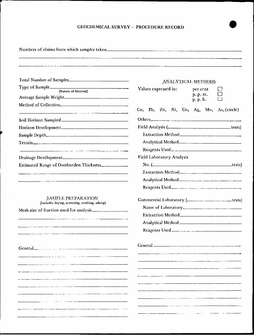
GEOCHKMICAL SURVEY - PROCEDURE RECORD
Numbers of claims from which samples taken.
Total Number of Samples. Type of Sample.
{Nature of Material)
Average Sample Weight———-^-^
Method of Collection^——————
Soil Horizon Sampled. Horizon Development.
Sample Depth————Terrain——————
Drainage Development.—————-——————
Estimated Range of Overburden Thickness.
SAMPJ-K PREPARATION(Includes drying, screening, crushing, ashing)
Mesh size of fraction used for analysis.————
j\N A LYTl C A L MF/liJOl)SValues expressed in: per cent D
p. p.m. Qp.p. b. D
Cu, Pb,
Others—
Zn, Ni, Co, Ag, Mo, As,-(circle)
Field Analysis (-
Extraction Method. Analytical Method-
Reagents Used___Field Laboratory Analysis
No. .———^^—.Extraction Method.
Analytical Method -
Reagents Used ——
Commercial Laboratory (- Name of Laboratory.—
Extraction Method——
Analytical Method,——Reagents Used ,^—.^—
.tests)
.tests)
-tests)
General__...— _.-. — .— .—.—.___- General
LOC\JOJ
l.
CL
CDQi"O
"k.C CD
o cu\-CD
C.M.T.
Lipton Twp. (Mri298)Derry Twp. (Mrl243)
8M+
593942 \5l.64
640933 i 690932630544 i 69094
(J30 i69IO*Z? i 691023 i 69*10
307 69i298 j 691! ^9 | 69
K9II 1 16953_ .. -J- — — -4- —
t,91052 691C'j3 ,-,--|o'xl '691055*-
t/ V V
^,910=3 j 6MCC4 '6,,:^ '^hZ? l 6 i, ^S- - -- - - -- —— — ~ — -- -J — — - - - - - - - - l -
595244 ^95250 +4M
IllVe 'G95F&8 1695178^ ^ _(__
l- IP IP i P 'P
'695/2^ 169^24^ -(6,9524J1 -
702618(70260 |7C262! '702623 1702631 1702632 ^702633""
P 'P 'P P " P ! P P
TO z 611 i yy?02620 1702622 ^02624 6 6 12 35 :G 6 l 2 56 16SI
695^26^ 4695Z4785 1693190 6
66^26 ' ( f 1^27 '661?.28 'CG'.29 6
?[695188 I69S204
i^~—ls^-1 —""—'—4^'-"— -i-U L"L JI"^ ^1 ^"'ZP'^'J. J.0ZJ !T'- '
y -693094/J695097 I695n7 \ 1695116 .695115 f69^!26 ,695T44
f-J 636'J '-y:5^ [ 63135^ 69.281 |69.276 69159
P l P i P l P
OC.T.39 ! 'C.T36
•39l3?0 t G'j:3Gl !69.'l3S6
S
4'M ^
Mosambik Twp. (Mrl3l9)l M
CD^t- OJ
i.
Q.
1-
O)C
EUJ
THE TOWNSHIP OF
LIZARDISTRICT OF
ALGOMA
PORCUPINEMINING DIVISION
SCALE: 1-INCH ~4O CHAINS
LEGEND
PATENTED LANDCROWN LAND SALELEASESLOCATED LANDLICENSE OF OCCUPATIONMINING RIGHTS ONLYSURFACE RIGHTS ONLYROADSIMPROVED ROADSKING'S HIGHWAYSRAILWAYSPOWER LINESMARSH OR MUSKEGMINES i CANCELLED PATENTED S.R.O.
or
^j-
c.e
NOTES
400' surface rights reservation along the shores of all lakes and rivers.
BATE OF ISSUE
Jft^a( l1B84f
PLAN NO.- 1299ONTARIO
MINISTRY OF NATURAL RESOURCESSURVEYS AND MAPPING BRANCH
43C1SNW0106 2.5970 LIZAR

REFERENCE
AREAS WITHDRAWN FROM DISPOSITION
M.R.O. - MINING RIGHTS ONLY
S.R.O. - SURFACE RIGHTS ONLY
M.+ S. -MINING AND SURFACE RIGHTS
Description Order No. Date Disposition File
42C1SNW0196 2.5970 LIZAR 210
l
C5
Q.
I-
tr < N
DERRY TWP. G-
--7/2 M
695391 (695422 l 6954235.t?*5j!f™L3—.i?!5 —- |89.53.E)L|*?*30S 161838L Jfi'MIBJ 8**38?.! -^-J.- - -.J- - -J - - - -*?34 ?4J6^* 4 L5Jf994i!6 s* 5*!2.! P lV——-N^S ^f 7 |P |P l P IX P l P I P j? | P , P ,P~~~ T ~
l^530 ' l l *^*\ l69539^ l 695430 i 695429 l , | 695396
6953JT 1695
^;,**y ' '69&I2 1695313 1695314
695547 |693592 j695593 f) 7/ .695595 1695596/1 695605J 695^047 (6956695428 ^95427 l /A^'lS 9552l '693520 I69S5IS J69555I 695550 *69S549 '695548
695405 69543I ] 69543 2 | 695433 '695434 A95435 .695S22 695556 (69559' | 695590 J^95589 |(L6955a8 j 695587 | 695606 | 6956D7 (6956,7
2?MIB^ 1 6953J7^6^94IO^,6 954OT ' l t ,W^DU^ pw:
|695326 6954ll ri-w I6954I3 16/54,4 6^95^62^ ^69556i|J^6564^ l 695565 |69556-J55 (\6_9558jJ 6^558^|^95 SJ9\ 695576^ (^93577 J^956 10^ ^fiJJ*^'__|6956I5^
69532! 695330 .695481 '695462 695483----h- -—|— - -te——-P P IP IP
l-— l- — — * ~ ~
695335 '695336 1695337 1695338 '695339 1695340-^695421 S95456 '69^5457 '695458 169,54,59 -~ — —i——— —-J- — — —i—— — —i — — — —i~~A~lr~~~~- "T - T- ^"i-695487 [69548B [695489 (695490 L69549I 69549Z JF ^^^ —— ——— ^ —— —— ——— —— —— —— —— ,——.—— —— —— —— i--^,—— —— i—— —— ——* —t
|P ,P
1695343W'" i l CT23
69534J^ J695_3^5_ '695344^_P ~ . P TP Ip ^ i P
695462 1695463 1699464 1695465 695496 '695497 1695496 169549*^,69^*94 1695493 \— ~ ~~r ~ ~~ — r — ~ —r~ 7~ — ^ ~~r— r~ *~695342 I69534IN '695461
l470 695469 695468 695467 1695466 — — — — — — —t — — — —i. — — — — — — —i
p -Tp Tp ipi 6.9. 5,54.7 699346 4.6 ?-5349- -
P P |P 'P
695507 j695506^ 1695^50P IP iP Ip
695,479^95^78 16^547^^9547^ ^695508 sgS^OJ^gsS ^ 695364 _ .___
P IP IP |P C
V l t/ 1695367(695366
P l P
l
O
-4/2 M
\-
o
DC
-I'/l M
71/2 M
CARNEY TWP. G-
REFERENCE
^^pnWIVHIB IMP" i™ i"
DATE OF ISSUE
JA:J s 11834Ministry of Na'.ural Resources
10RDNTO ——
LEGENDHIGHWAY AND ROUTE No.
OTHER ROADS
TRAILS
SURVEYED LINES:TOWNSHIPS, BASE LINES, ETC.LOTS, MINING CLAIMS, PARCELS, ETC.
UNSURVEYED LINES:LOT LINESPARCEL BOUNDARYMINING CLAIMS ETC.
RAILWAY AND RIGHT OF WAY UTILITY LINES NON-PERENNIAL STREAM FLOODING OR FLOODING RIGHTS SUBDIVISION OR COMPOSITE PLAN RESERVATIONS ORIGINAL SHORELINE MARSH OR MUSKEG MINES TRAVERSE MONUMENT
DISPOSITION OF CROWN LANDS
TYPE OF DOCUMENT SYMBOL
PATENT, SURFACE.* MINING RIGHTS—................ 0.SURFACE RIGHTS ONLY...———_.......... O, MINING RIGHTS ONLY ..,_.............._.. O
LEASE SURFACES MINING RIGHTS™.-...™......—— H
" .SURFACE RIGHTSONLY.__...™.............. B
" .MINING RIGHTS ONLY ..^...———.™........_.. y
LICENCE OF OCCUPATION .._,._......,.....™_.. T
ORDER-IN-COUNCIL ........_.———...__....-...-,.. OC
RESERVATION ___......__............_............. ©
CANCELLED _.....—————.....————.........M... ®SAND S GRAVEL m...................™,™^.™...-.. ©
NOTE: MINING RIGHTS IN PARCELS PATENTED PRIOR TO MAY 6, 1913, VESTED IN ORIGINAL PATENTEE BY THE PUBLIC LANDS ACT. R.S.O. 1970, CHAP. 380, SEC. 63, SUBSEC 1.
SCALE: 1 INCH ^40 CHAINS
FEETO 10OO 2DOO 4OOO 6000 800O
O 20OMETRES
10OO(1 KM)
2000(2 KM)
TOWNSHIP
ERMINEM.N.R. ADMINISTRATIVE DISTRICT
HEARSTMINING DIVISION
PORCUPINELAND TITLES/ REGISTRY DIVISION
ALGOMA
Ministryof LandNatural Management
Resources BranchOntario
Dat * DECEMBER,1982Nmnbtr
G-2292

Lipton Twp (IVW298) Derry Twp. \
t 4M 2 M
CT.73
CT.72
CT.59
• VCTBO' 690929,] 69O926 |6909 19 ' 69C9I6 j 69C909 690 3 06 j 6908*99
6909*43
&9C939
CT70
i, 69C320 t 590915 , 6 30910 ! 8*C905
69G324, 690921 ' . . .P l
^CT65 " W *T"
690931 S l ^XtT.67 " '590911 i 690904 | 6909/
IP \- ' l V.
' i CT 115 •*53O2 '695303•--r: ——
•695512
Boot
•\
C.T6I
Boy
ffc
C3 E?
p i P 6309.2
690944 J 690941 l 690940 l 690933 i 690932 l 690923' 590922 X903I3 | *f Jt*9C9O3 l 690902 ij*iS*L j-?"* —
691018 1.691017 [691008 691OO7 , 63U938 '6912:8 |69i2'- i69'207 691(38 ^?*2t2 |69512J~ ' "
691019 69)016,69i009 1591006 l 64O999'691226 '691219 [69l2l6 .631209 '69)206 691193
69.U9A JP l
P l Pi
691027 69I025N4^91020\J 691015 i 691010^
' 6 91 225 '691220' *91215 !69I2IO'69U05 ' P . .P P P P
P l P
5289
P
103C
f
\ 691028
1 0
1,69l029
i P
! 691024.
1 P 1
1 1j 691023 |
, P
691021
P
691022
P .
v*9IOl4
P
691013
Jli
| 691011
1 P 1j 69*012
1 P
eVioo*
1 'l1 69IOO3
1 P
| S9IOOI j69(22* , 691221
IP 'P t' P' ! ii 691002 691223 |69I222
1 P 1 P 1 691102
691214
P
69121 3
P
i 691 211
\ p i
1 691212
P
i 691204
i P
1[69I2C3
P
691201
P
691202
P
S'**?*' l63'327 6913 l S fa9l3l7 69i3CS 69\I307 l 69t298 | 691129 1691124 69112 360' T
'\9MOI 631100 ! 591093 691098
P l P ' P i P
' 6913 19 i 69!3i.3 , 59I4G* '-'
\ v l p l p i y p
l p l p i p 'p ll l l l l l l|69M25 l 69-122 i o9!!03 j 69UO4 | 691105 | 691)06 1 691107
*CTS5
691334/169 1329 is 31321 .691320 l 691315 169I3IO jfc9i 3 OS l69I3C:
1 6313:4 16*1 1691333 .691331-1691324 ;69!32i ,—
l ! l l31)3) •69112^ |69M2I i 69 11 t 2 |69I I69IL .691108
695327^ '6*^328
crus695329^1 69513O
fp^criti
M
195335 '**353*
69534ft
P l P IP
69^304 69^1301^ 69,132 J 631*27 L69II20 J69III5 i 69M13 S95236 '695237 095257
P j P
I69III6
691031
59133!P
69'03? ,Windy Pt.
69)114 [695235^ '695238.
f , P IP
•r 101I69H-7
42C16NWeiB6 2.5970 LIZAR S20
'O/J-5.
'90346 690,47
P l P
G90955-
500689(500690
671046P
l?O069*
69105*.
CT33
in;?3T Cr-H'j ,5'JH3E (691118 1695214•*— 7--,— 7 -- J~~p~~ ~P~ ~~jpl l l
.695216
J.6*? L"
^695239T "~ ""
l 695353 (695354
l 695364 16951*3
693565^6953*6r
W5374 69SJ7Vl P
1375 J-'"P,
.695232 "695241
|P
54 69C9S' ^3'). t , r ^ —— jJL li -ll?"^. J ;691074 [69I.66X
690987 f -5939B2 69
p FT —
69' *88|6909?: -- T -
f'V(075551*07552
500698'
500 rt c*-X rP500699 '
500697H
)
691146
166 . 59106? , — -L —— — l, P l P
691 142 .69114 l/ ' 691140
. '407533
P ,P
6t P I4C75! p i
C.T.46
-1IP
95179
IP
CT26 t |, , i l(595)81 '695j9^ 1695198 2,695^1^^695^20 .69^5230 '69524^ 169525J -~ ~ ~ "*~ ~ ""p ~ /~!P~ IP .p ~V tpP
J695/J8T-
( 69M76 issues' i**. 63 p l"~ T~ "1 ~ r ~^~~ ~
,P
IP.
. tllT41631172
|895ii3 '^95159'"""'""" [695HB2 /J695I75 '695I8J
CT 87 P/ l P" " ^
ll
.1695174
'69 MO T
'p l P li' , P |"
f ' ! i39JI^70 l 691265 |69(242 i 691241 ,p r i~ w T"~ ~^ T69i?*4(6i* a: ~~~"~ p H6?5 173^695171
l"p ~ p ~
Tt C _ 7 ,P ' P \ P
'- i l '1695192 [695200^695209 69522^ "695228
|p p i p , p y Tp* 95*91 f Qf 7/1 1 l c&c *fia y^Q ^>>x ^ctt^>>"T
JO79CU 1 Q73^UV jO v7 ^ t C. J D7?CC '
,P ,P |P ^ P P
1 1 1 '
iKQ*.mn fi*-i?n^ Ifi4s?q7r 169527* JBifitIP , IP 'P / *JPi ^^X-j 1 \ XV'-T ^-wX^V "X,*5I89 |69SZ03 1695^6^ ,695225f— 7^^1695(88 1695204 |64*2O5 \IF 11
[^95172
ii
- ' — — — -H— — -~|P 'P11
11695245 ^695240
'P ,P1
1 t
ip p
,
^9^47
k.
ivA
tt
W't-"9 69IIK7 - ' L ! C.T43 IS 1""" 'ill l l^-~\ IJ J J. J. L J8**^9? .^5*59?,*-.**^**. J. J^il jT.tf-^l6** 1 !S95I3^ jWSW* ^95149 ^gs^ ,695169 r 6951 TO
.''P ~;P ,p rp i P /*|cT.42^1p~ " {P ~ ,P~ ~ ~ TP~ ~" ~IP~ ~f"TP~ ~ ~ i
~v— - — f— — — — * — — — — i— — — — — — — A i?— —— LJx!L — — —l — ' — _.* y y |695I46 i \ |S95)69 l"p69509495097
T U NDRA C3;o uo VA i M
l l91^78 j 6912/3 ( 69(254
P l P |~ 7 ~;
l f :'.*2'9 (691274 (631255 .69(256 , ft
p i P i T ~~~ r^ir?'i9"iji9ij7i li9:! 5j 'l91 "!^^.
P l P l P ' f ~ Xpy '
V bVVUrO rOT^V^B , OT^V^D |*^3U^*/^ ,1 ™- l ^^ — .^r^ i* — ' ^^^ ^^| L*. ^^ -^ ^ — — i. i-
l "^-/P /| P ' p /lL.-.^/^i i ()*i J(695073 l'6/9*5079 '69508? 6.9MO96I -K-S- ~ -WD- ~ ~ h." T——l lil T i
,695**ft' 1695086
'69*0*4 *9t07]
[691276 1691^59KU
95053
)59
695058P
J695O65IP
.95054^9W5^
950.55, 695056V
l 372- 1695082
rft9S07' .69508 i ~ — ™ p — ~
j l l (69^067 : 695070 j 695084.
5M
^
-l
5*5 'i8^ t?l5 Li' — |i*l' ?J . 169514^695146
fa
-' fix" -1V .695(2!
^512 4 ^CT.;T.39 'C.T36
CT.54
"(f
THE TOWNSHIP OF
LIZARPORCUPINE
MINING DIVISION
SCALE: 1-INCH ^ 4O CHAINS4M 3M 2M l M

r
', ,-* ** ' '' '"'i 'IJt, '-.'?-' -^ I 1 . '
'-./X .Sff' . '
' : ilP!llft-i"'".i.'.1 ' -r,' -t 1 . ••'i-:', i'- M .1..-.v, !'i'j,,l v. - !; ' .-.^Vi-•••..'v^.^j
19
•^;. 20
21
23
——— r^i—— , ———
3 ——^ ————— jQ.
———— y,—
f/22 ^ i
X— y -o r29224 -^ ——— r
25 -JSQ ——
i^/^ 222 r* J""T i ——— T^1 i ' ""— 'i " ' i . r i —r j^-7 ' ' 690 r ' '
*Q —— i ————— i ————— . 77Q ^5 i ————— r—
— JflO ———— . ————— r^3 ——— , ————— , "O , ——*VLX 1 1 - r 1 ?gft~/ l
JQ/-S _______ /^. _________ 269 —————————^———— ^GH ——— 5G "870 ^ ' '
S SQ| ——— i ——— i ——— i —— b© — i\
—— ^~S..-X~V ^W X^*l;O^O ;Q ——— i ——— i ——— i —/'
1 j/ ' 980 ' 1 2O
,-^S;'.'*^-" * " ^2^ s^ - ^^ ??**r "n ??4 . - i , , , , , hn , ^vi i i ———— i ———— i —— sQ ———— rTs^ —— i gO i ———— i ———— i ———— i ———— i ———— i ———— i gO if ——— rm —— r-^—i ——— -i ———— ' IW-T" i i i i r^ i i p^ . ^M. i r-
\ *y————————————— le —— Bq-^ —————————————————— ——— s^ ————— — - —————————— , yf . 740;o ——— . —————— v- ——— , —— i ———————— , So^ Ay. —— . — se ——— . —— . —— . —— . —— . ^5 .,10 ——— ?© ——— —————— ;o.^o —— 620 /c(y ———————————— v
®i i ®/ x, -in i . ^Or-^1 — i-^o-'-o i "O,so , ^n . ,^-n, , , — i —— i —— w —— r^o . —— i —— i —— i —— i —— i —— -. — ~r- ^I^^O^GI i i , , , ^4 ,T z\~S' ' iv-'T ' *V^ -jV-' 1 i^^l^W 1 u.\I7 1 1 ^ nj\-/ l 1 1 ' ' ^ ' abO/-^ ' ' ' ' ' ' ' ' o^i'^aiv-y-:x-L^40 ' ' ' ' ' '
V 'N^N 777 X-i^-N W y-V SV^^X-X ../-N ./-N 2/8 ' /^N 279 ?Rfl ^ . -^\ ^ '
1 "tU -I 890 ' "" T"* '^^2^ ' ^ ! SU^Ul 1 2CJ I 900 SU) 1 1 1 1 1 1® . 1 I 2U ^ 910 1 1 1 1 |T5 1 l^i oUl I 920
^ 258 /N."O WI i "O i ^O r - 'i - i " -r- - -r- - -i— Bi—— —— T- -H^B —— r^2-© ————— 1iJo ———————— i ———— i ———— i ——————— vtfS*-— —— —— ' 3^ v i ———— i ————————— i ———— -^-^-I 1 l -jVy "geo^ l iV/ 1 a,\-/ 1 1 1 i I 1 u.^-7 ' ago uV^ i c.V^ ' ci^-^ i i i i i 94Q m v^xi \ 930
"^ 2S 9 ^ ~Pi i "-i - "O ——— i - ———— r*Q —— ^ ———— r - n(7l 'f^n -"P^1^) 0 P) -i — -- —— r-" ^ - i - -r - , ^3-i ——— i —— S^P ——— ' —— ^ — ro ————— 155 —— ' Hu^ ' ' ' ' ' ' ' ZtrtoQ ' f ^w ^ ' xu? ^UAJ iU^U Gt7 i r^To ' ' ' ' ' ^T1 ' !
27
6 3(4 3 ,
— i —— i ——1 1070 '
^ ID/^S mS~\ ~S~\ dJ2^ JJU 1 1060 ' ' ' 1~" —————————— 1 —————— 3O QO ' V ————
^n/^N ^/-\ 320
' ' <XS' ' m^ ' ' ' 1080 ' '
™n1 ' o"H^50 ' ' - i 1 1 1
"O -n1 ' 0W ' 0^ III, )090 | |
——— l ——————— - 44 ' m{~*\ W/-N 3JO1 - ' 'iowP ' CO -i —— s — i ————
—— , —————— , ———— aC3^ ——— , —————— l^p —— 322 ^/~NUJM^ i i w i y , ^ i )]00 i
^s. ao9I+. i i i 1030 i \ ' ' '
\
1 1 r 0 1 ^^^
29
28
30
495 1?^ k
/V f
1 v 1 l/fo 1
/ 0 /^V?^t;o ^wtf9 | ———— --..^,, .
1250 ' ^^ '
X
iriy**~*\ iji*W\—— .. w. -i —— . —————— | —————— P — -j —— i —————T o.^^ ' ' ' o^-^ ' 11 50
w ^n , ^ 3 i'1*0 uU i i ' -
358
^-^e ————— s© —————————— :o , 1UO qo ——— i ——— i ——— i —— - v ^r\ w1 ' ' ' 'ii8o ' ' ' ' ' aU ^i
———— fO —— ———— ie ——— . ;0.;0 ————————— , —————
oJ/^^32 •./-N ^^\ m^-\ to/^^U 13 a\Jt JU i i ujUl S^1 ' I ii3o"""
————— iCiP -so —— ?e —— ————
——— i ——— T —— -©T ——— NQ flO i NOQ ———— r^ ——————1230*-^^^ m^J/ Q^X i o^— 'm^*' ' '
M O ^'^r^ t*/1 Q-^ 1 mV-V 1 ——— 3^7 ———— T— *V1 120 ™ ,^y(o '
' ——————— ^TO ——————— ——————— V
_________ pr^ __________________ j35* iR^ ^l 1 ^1 ' )220 ' ' ' ] ~l ——————— ———
V-
— ffifQ —— j ———— , y1 1260 '
1 1 1 1 1 ^6 1 i W i i1270 '
,^Q , ———— p1 m^J ' '
—————— ——— BP| fi o^
9 iQ-O i ———d^-^uj^-^ ' i iWlo ' ' -/^ 3691 ————— 1 —— 71 —— * —— l ————— l ——
'1290 '
5ZQ i — — r-|Q ——— , ———————— *- X
e—io sil -o
'' *- "' ' '"
1 . ' l 'sN, v.'MO
; Allii41 i*V. -^vSr1 - A Jf^-- - - ^Su**'- .- *SX'-'*Y,-" -- '.u^." •J-f:.^m - ' '?* - ' fc-frV-^^!^' ••-T^" . : *."' ; - - *- - '\- -fSV?:r v -
s f ;^m:*™-.' ;;fli ?*sA "SXJte*.
^tv '' ^''/\ /^ir* V -V /VV!--
V. ^? 5"x"\
jf . . ^'f,.,' ^;.1 ' ' 2940 ' ,f,t '. *- .V•-r/
, ,-,. .-^^^7\
•JM-r
*
y^ x


^^SS^^^^\^^^^5f^^
Kfo^r^^^ss \v\ * s^h