hybrid passive control in steel moment frame buildings
TRANSCRIPT

13th World Conference on Earthquake Engineering Vancouver, B.C., Canada
August 1-6, 2004 Paper No. 2387
HYBRID PASSIVE CONTROL IN STEEL MOMENT FRAME BUILDINGS
Tumay DOGAN1, Barry J. GOODNO2 and James I. CRAIG3
SUMMARY
Reliable seismic damage control can be achieved by base isolation systems and/or passive energy dissipation (PED) devices. Base isolation reduces the seismic response of the structure by “decoupling” the building from the ground for certain frequency ranges using structural elements with low horizontal stiffness. PED devices such as advanced ductile cladding connections are designed to dissipate a large portion of the earthquake input energy, which ordinarily the structure would be forced to dissipate through inelastic deformations.
While either of these approaches alone is capable of reducing seismic response to acceptable levels, it is reasonable to examine whether a combination of these techniques might be more effective in terms of both performance and cost. In this situation, a base isolation system would not be required to provide full isolation, and at the same time the PED devices would be required to absorb only the seismic energy transmitted through the isolation system. In this study, base isolation and advanced ductile cladding connections are used in combination to maximize the cost reduction, while improving serviceability and reducing ductility demands in steel structures subjected to moderate and high seismic events. Extensive nonlinear time history analyses of hybrid base isolation systems with advanced ductile cladding connections are carried out using RAM Perform 2D software (Powell 2000) for a reference steel test structure to investigate their effectiveness. Results show that properly designed advanced ductile cladding connections are capable of providing significant levels of performance improvement, in terms of either enhanced serviceability (e.g., reduced peak displacements, accelerations) or reduced seismic demand on the primary moment frame structure. Ductile connectors can be combined with base isolation systems to maximize energy dissipation and to decrease peak drift. Selected combinations of base isolators and advanced ductile cladding connections provide performance improvements based on selected performance measures such as reduction in base shear. Various combination schemes can be optimized globally and then analyzed for a variety of ground motions with different spectral characteristics to evaluate their effectiveness over a range of possible ground motion inputs.
1 Graduate Research Assistant, School of Civil & Environmental Engineering, Georgia Institute of Technology, Atlanta, GA, USA. Email: [email protected] 2 Professor, School of Civil & Environmental Engineering, Georgia Institute of Technology, Atlanta, GA, USA 30332-0355. Email: [email protected] 3 Professor, School of Aerospace Engineering, Georgia Institute of Technology, Atlanta, GA, USA 30332-0150 Email: [email protected]
INTRODUCTION
Base isolation reduces the seismic response of the structure by “decoupling” the building from the ground for certain frequency ranges using structural elements with low horizontal stiffness. This gives the structure a fundamental period that is much higher than its fixed-base period. Most isolation systems used today have either elastomeric bearings (natural rubber or neoprene) or sliding bearings (Teflon and stainless steel). Combinations of elastomeric bearings and sliding bearings can also be used.
PED devices are designed to dissipate a large portion of the earthquake input energy, which ordinarily the structure would be forced to dissipate through inelastic deformations. Viscous dampers and hysteretic devices are examples of PED devices that are available. These elements are often inserted into diagonal bracing elements.
While each of these approaches alone is capable of providing significant reduction in the seismic response of a structure, the methods used are distinctly different and rely on very different behavioral mechanisms. Base isolation focuses on structural isolation while viscous and hysteretic dampers focus on hysteretic energy dissipation. This paper will examine whether combination of these methods can provide substantially better performance than that resulting from the methods applied individually.
ANALYTICAL STUDIES
Base isolation and PED devices (ductile cladding connections) were used in combination to improve the serviceability and ductility demands on a steel frame structure subjected to moderate and high seismic events. An existing six-story steel test frame used extensively by the Multidisciplinary Center for Earthquake Engineering Research (MCEER) for both lab and analytical studies was selected for these analyses. The test frame without cladding was used by MCEER to study the influence of active tendon systems and active mass dampers on the seismic response of the structure (Reinhorn 1989). The 1:4-scale test frame, with three bays in one direction and one bay in the other, has the dynamics characteristics of a six-story moment resisting steel frame structure. The total weight of the structure is 42 kips. The frame is 216” tall, 144” wide and 48” deep and is represented as a 2D model as shown in Fig. 1. All of the structural members are S3x5.7 shapes and Fy = 36 ksi. The properties of each frame member were doubled to account for the two parallel frames in the three-bay direction. Masses were lumped at the horizontal and vertical degrees of freedom (DOF). The effect of masses at rotational degrees of freedom was ignored. Damping values are 1.42% for the first mode and 2.04% for the second mode, as determined from experimental results (Reinhorn 1989). The structure was scaled according to the artificial-mass simulation method. The case study structure, referred to as the reference (bare) frame (REF), is a modified version of the original test structure. Concrete cladding panels were assumed to be attached on the both sides of the frame in the three-bay direction. Two story-to-story panels per bay were assumed. Each panel was assigned a weight of 0.15 kips; bringing the total weight of the structure to 52.8 kips.
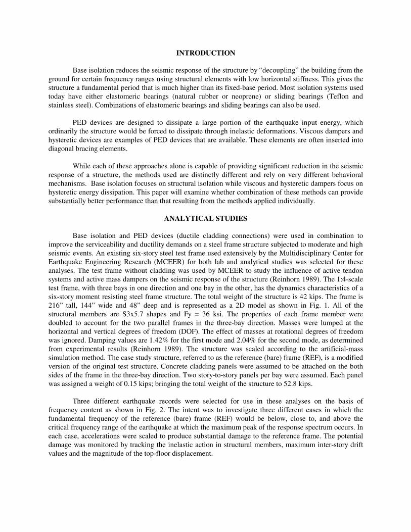
Three different earthquake records were selected for use in these analyses on the basis of
frequency content as shown in Fig. 2. The intent was to investigate three different cases in which the fundamental frequency of the reference (bare) frame (REF) would be below, close to, and above the critical frequency range of the earthquake at which the maximum peak of the response spectrum occurs. In each case, accelerations were scaled to produce substantial damage to the reference frame. The potential damage was monitored by tracking the inelastic action in structural members, maximum inter-story drift values and the magnitude of the top-floor displacement.

Four different combinations of PED and base isolation systems were analyzed as listed in Fig. 1. The first three cases are the reference (REF) and individual schemes alone (BI, DC); the combination scheme is referred to as BIDC in presentation of results below. The first scheme; (REF); includes only the bare frame and cladding panels that are assumed to be isolated from the inter-story drift motions of the frame. These panels contribute only mass to the dynamic properties of the building without any contribution to the lateral stiffness, representative of the conventional design philosophy of nonparticipating cladding.
In the second scheme, referred to as Base Isolated (BI), four base isolators were added at the base
of the REF scheme. In the third scheme, Ductile Cladding connections (DC) were added in REF at the top cladding panel connections as shown in Figure 1, so cladding participation was imposed through the ductile upper connections. The last configuration was a hybrid scheme (BIDC) which was constructed using the combination of Base Isolated (BI) and Ductile Cladding connections (DC) schemes.
Figure 1. Building Design Model
RAM Perform 2D (Powell 2000) was used to carry out all analyses reported here. For verification, schemes REF and DC were also analyzed using both DRAIN-2DX (Prakash 1993) and RAM Perform 2D (Powell 2000); the results were found to be in very good agreement. Further descriptions and assumptions inherent in all element formulations used can be found in the RAM Perform 2D User’s Guide.
48 inch 48 inch48 inch
144 inch
36 inch
36 inch
36 inch
36 inch
36 inch
36 inch
216 inch
CLADDING PANEL
BEARING CONNECTION
DUCTILE CONNECTION
BASE ISOLATOR
STEEL MOMENT FRAME
Ductile Cladding Connection
Elastomeric Base Isolator
Scheme-REF-Reference Frame Scheme-BI-Base Isolation Only Scheme-DC-Ductile Cladding Connections Only Scheme-BIDC-Hybrid (Base Isolation & Ductile Cladding Connections)
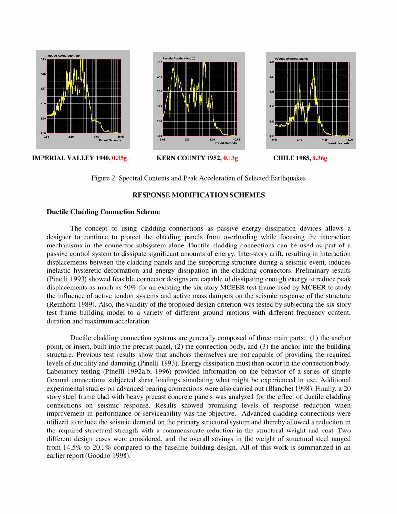
Figure 2. Spectral Contents and Peak Acceleration of Selected Earthquakes
RESPONSE MODIFICATION SCHEMES Ductile Cladding Connection Scheme
The concept of using cladding connections as passive energy dissipation devices allows a designer to continue to protect the cladding panels from overloading while focusing the interaction mechanisms in the connector subsystem alone. Ductile cladding connections can be used as part of a passive control system to dissipate significant amounts of energy. Inter-story drift, resulting in interaction displacements between the cladding panels and the supporting structure during a seismic event, induces inelastic hysteretic deformation and energy dissipation in the cladding connectors. Preliminary results (Pinelli 1993) showed feasible connector designs are capable of dissipating enough energy to reduce peak displacements as much as 50% for an existing the six-story MCEER test frame used by MCEER to study the influence of active tendon systems and active mass dampers on the seismic response of the structure (Reinhorn 1989). Also, the validity of the proposed design criterion was tested by subjecting the six-story test frame building model to a variety of different ground motions with different frequency content, duration and maximum acceleration.
Ductile cladding connection systems are generally composed of three main parts: (1) the anchor
point, or insert, built into the precast panel, (2) the connection body, and (3) the anchor into the building structure. Previous test results show that anchors themselves are not capable of providing the required levels of ductility and damping (Pinelli 1993). Energy dissipation must then occur in the connection body. Laboratory testing (Pinelli 1992a,b, 1996) provided information on the behavior of a series of simple flexural connections subjected shear loadings simulating what might be experienced in use. Additional experimental studies on advanced bearing connections were also carried out (Blanchet 1998). Finally, a 20 story steel frame clad with heavy precast concrete panels was analyzed for the effect of ductile cladding connections on seismic response. Results showed promising levels of response reduction when improvement in performance or serviceability was the objective. Advanced cladding connections were utilized to reduce the seismic demand on the primary structural system and thereby allowed a reduction in the required structural strength with a commensurate reduction in the structural weight and cost. Two different design cases were considered, and the overall savings in the weight of structural steel ranged from 14.5% to 20.3% compared to the baseline building design. All of this work is summarized in an earlier report (Goodno 1998).
KERN COUNTY 1952, 0.13g IMPERIAL VALLEY 1940, 0.35g CHILE 1985, 0.36g

Cladding Panel
Upper Floor
Lower F loor
Bearing connection
Ductile connection
Elevation showing ductile upper connection
Deformation
Force
Stiffness
Yield force
Yield force
Ductile connector transverse shear behavior
Figure 3. Representative Cladding Connector Design Model
The cladding connector design model represents an elastic-perfectly plastic material model acting in the horizontal direction only. This model is appropriate for mild, ductile steel attachments used in simple arrangements; more complex geometric configurations for a particular connector could introduce other effects and require more complex models. Here, the simple piecewise linear elastic-perfectly plastic model is assumed as an appropriate design model for the connector. The resulting design variables are taken to be the initial linear stiffness and the yield force (Figure 3). These connector elements are modeled in RAM Perform 2D using its “seismic isolator elements” because they incorporate no stiffness proportional damping. The cladding panels are modeled using elastic infill panel elements that deform only in a shear mode. Base Isolation Scheme
The seismic isolators at the foundation interface are modeled using elements of the same name as provided in RAM Perform 2D. Figure 4 illustrates the geometric configuration and assumed properties for these elements.
Figure 4. Base Isolator Element (taken from RAM Perform User’s Guide)

DESIGN CRITERION AND RESULTS
For ductile cladding connections, an initial connector stiffness of 5 kip/inch and a yield force of 0.2 kips were used based on the optimal solutions developed by Pinelli (1993) for the same structure. The optimal solution considered a low level of dynamic ductility to insure that the connectors would not fracture due to low cycle fatigue. The base isolators were designed by adjusting the initial stiffness from 1 kip/inch to 7 kip/inch in order to reduce the input seismic energy as much as practical. It should be noted that for each of the basic schemes considered in this study, the devices were designed to provide a reasonably optimal level of performance, either by reference to previous work for the cladding connectors or by numerical experimentation in the other cases.
In order to identify the best possible design for advanced connections in combination with base isolators, many different performance measures were considered, such as total earthquake input energy, inter-story drift, base shear, base overturning moment, inelastic action in frame members, hysteretic energy dissipated in ductile cladding connections, and displacement and acceleration values at different floor levels. From these performance measures, various design objectives were selected such as minimizing the total input energy, base shear, inelastic action in frame members, and also maintaining sufficient energy dissipation ratio Ec/Ei, where Ec is the total energy dissipated in all the connections, and Ei is the relative energy input at the end of the ground motion.
At the same time, several constraints were considered, such as ductility demand in the
connections and base isolators, minimum code requirements for the strength of the connections (based on Eq. (36-1) in Section 2337 (b) 4.B of the Uniform Building Code (1991)), as well as limiting the magnitude of forces induced in the panel by the connections to 10 kips (Pinelli 1996) so that the panel capacity would not be exceeded.
For the parameter studies of Scheme-BIDC, the base isolator initial stiffness was varied between 1
to 7 kip/inch and was used in combination with a range of connection stiffness (1 to 6 kip/inch) and yield force (0.1 to 0.6 kip) values. The 3-D color plots in Figure 5 show results for the 1940 Imperial Valley ground motion case: Scheme-BIDC (Fig. 5(a)), with base isolator stiffness, Kb, of 3 kip/inch is compared to Scheme-DC (Fig. 5(b)). Figure 5 shows how the earthquake input energy varies as a function of connection stiffness and yield force. Since there were three variables and a specific performance objective, only the sample results of the parameter studies with fixed stiffness of base isolators are shown in Figure 5 for clarity. The plots in Fig. 5 show that adding base isolation to ductile cladding connections on the test structure (i.e., Scheme-BIDC) results in a reduction of input energy to one half of the Scheme-DC values. Also, the location of the peak input energy was shifted from a stiff cladding connection to a flexible connection case with the addition of base isolation. The performance of the hybrid case (Scheme-BIDC) will be considered for additional ground motion cases as discussed below.

Figure 5. Total Earthquake Input Energy Comparison for Scheme-BIDC* and Scheme-DC (* Base isolator stiffness, Kb, of 3 kip/inch)
Figure 6. (Ec/Einput) end (%) for Scheme-BIDC** (** Ductile cladding connection stiffness, Kc, of 5 kip/inch)
From previous studies by Pinelli (1993) and current studies, it was concluded that initial stiffness
of the ductile cladding connections was not a key factor in determining the ratio of energy dissipation at ductile cladding connections to input energy and ductility demand of ductile cladding connections. Therefore, for Figures 6, 9-11, only a single fixed value of ductile cladding connection stiffness, Kc = 5 kip/inch, was used.
The color contour plots in Figure 6 display values of the energy dissipation ratio (Ec/Ei) (see
numerical values assigned to each contour) for three different earthquakes when base isolator stiffness (vertical axis) and cladding connector yield force (horizontal axis) are both varied. The energy dissipation ratio (Ec/Ei) for Scheme-BIDC is quite high (i.e., 80% provided that cladding connection yield force values are low), as shown in Figure 6 for three different earthquakes with different spectral characteristics. Inter-story drift was also reduced when base isolators were used with ductile cladding connections (i.e.,
SCHEME-BIDC
(Ec/Einput)end (%) (Kc=5kip/inch)
Ductile Cladding Connection Yield Force (kip)
0.1 0.2 0.3 0.4 0.5 0.6
Bas
e Is
ola
tor
Sti
ffn
ess
(ki
ps/
inch
)
1
2
3
4
5
6
7
70
70
70
7070
6060
60
50
50
5040
40
30
30
30
20
10
10
10
30
30
20
20
20
80
80
80
80
40
40
40
50
50
70
70
60
60
60
60
80
80
80
80
(Ec/Einput)end (%) (Kc=5kip/inch)
Ductile Cladding Connection Yield Force (kip)
0.1 0.2 0.3 0.4 0.5 0.6
Bas
e Is
ola
tor
Sti
ffn
ess
(kip
s/in
ch)
1
2
3
4
5
6
7
70
70 60
50
50
40
50
5050
50
4040
40
3030
30
2020
20
10 10 10
6060
60
60
60
60
80
7070
70
70
70
80 80
80
80
80
(Ec/Einput)end (%) (Kc=5kip/inch)
Ductile Cladding Connection Yield Force (kip)
0.1 0.2 0.3 0.4 0.5 0.6
Bas
e Is
ola
tor
Sti
ffn
ess
(kip
s/in
ch
)
1
2
3
4
5
6
7
70
70
70
70
70
70
60
60
60
60
60
50
50
50
50
40
40
40
40
30
30
30
30
2020
20
20
1010
1080
80
80
80
80
12
14
16
18
20
22
24
26
28
30
0.1
0.2
0.3
0.4
0.5
0.6
12
34
5
Tota
l Ear
thq
uake
Inp
ut E
ner
gy
(kip
-inc
h)
Ductile
Clad
ding C
onnectio
n Yield
Forc
e (kip
)
Ductile Cladding Connection Stiffness (kips/inch)
Total Earthquake Input Energy (kip-inch) (Kb=3kip/inch)
12 14 16 18 20 22 24 26 28 30
20
30
40
50
60
70
0.1
0.2
0.3
0.4
0.5
0.6
12
34
5
Tota
l Ear
thqu
ake
Inpu
t E
ner
gy
(kip
-inc
h)
Duc
tile
Cla
ddin
g C
onne
ctio
n Y
ield
For
ce (k
ip)
Ductile Cladding Connection Stiffness (kips/inch)
Total Earthquake Input Energy (kip-inch)
20 30 40 50 60 70
(IMPERIAL VALLEY 1940, 0.35g)
(IMPERIAL VALLEY 1940, 0.35g) (KERN COUNTY 1952, 0.13g) (CHILE 1985, 0.36g)
(a) SCHEME-BIDC (b) SCHEME-DC

Scheme-BIDC). The color contour plots in Figure 7 display values of the energy dissipation ratio (Ec/Ei) (see numerical values assigned to each contour) for the same earthquakes when connector stiffness (vertical axis) and cladding connector yield force (horizontal axis) are varied. Figures 7 and 8 show that the hybrid scheme (BIDC) provides energy dissipation similar to Scheme-DC for low values of connection yield force.
The color contour plots in Figure 8 display values of earthquake input energy (see numerical
values assigned to each contour) when base isolator stiffness (vertical axis) and cladding connector yield force (horizontal axis) are varied; these results are only for the 1985 Chilean ground motion. Total input energy amplification was observed for the ductile cladding connection only scheme (DC) for the Chilean ground motion by Pinelli (1993) since the frequency of the clad structure (DC) is very close to the critical frequency of the earthquake. The ductility demand of the connections is also increased because of the high demand for energy dissipation. However, the earthquake input energy amplification problem was eliminated as shown in Figure 8(a) by the addition of BI to DC (creating BIDC); here the dynamic characteristics of the structure are altered so that the hybrid system (BIDC) is much less sensitive to ground motion. The hybrid system (BIDC) reduced the input energy of scheme DC by a factor of 6 or more.
(Ec/Einput)end (%)
60
60
60
60
60
50
50
50
50
50
40
40
40
40
30
30
30
30
20
20
20
10
10
10
70
70
70
7080
80
Ductile Cladding Connection Yield Force (kip)
0.1 0.2 0.3 0.4 0.5 0.6
Du
ctile
Cla
dd
ing
Co
nn
ecti
on
Sti
ffn
ess
(kip
s/in
ch)
1
2
3
4
5
6
(Ec/Einput)end (%)
20
20
20
20
10
10
10
10
40
40
40
40
40
30
30
30
30
30
60
60
60
60
50
50
50
50
50
70
70
70
8080
Ductile Cladding Connection Yield Force (kip)
0.1 0.2 0.3 0.4 0.5 0.6
Du
ctile
Cla
dd
ing
Co
nn
ecti
on
Sti
ffn
ess
(kip
s/in
ch)
1
2
3
4
5
6
(Ec/Einput)end (%)
80
80
80
80
70
7070
70
70
60
60
60
60
50
50
50
50
40
40
40
40
30
30
30
20
20
20
10
10
Ductile Cladding Connection Yield Force (kip)
0.1 0.2 0.3 0.4 0.5 0.6
Du
ctile
Cla
dd
ing
Co
nn
ecti
on
Sti
ffn
ess
(kip
s/in
ch)
1
2
3
4
5
6
Figure 7. (Ec/Einput) end (%) for Scheme-DC
Total Earthquake Input Energy (kip-inch) (Kb=3kip/inch)
Ductile Cladding Connection Yield Force (kip)
0.1 0.2 0.3 0.4 0.5 0.6
Du
ctile
Cla
dd
ing
Co
nn
ecti
on
Sti
ffn
ess
(kip
s/in
ch)
1
2
3
4
5
6 44
42
40
40
38
38
36
36
36
34
34
34
3232
32
3232
3232
32
30
32
32
30
3030
30
30
28
Total Earthquake Input Energy (kip-inch)
Ductile Cladding Connection Yield Force (kip)
0.1 0.2 0.3 0.4 0.5 0.6
Du
ctile
Cla
dd
ing
Co
nn
ecti
on
Sti
ffn
ess
(kip
s/in
ch)
1
2
3
4
5
6
340
340
320
360
320
320
320
300
300
300
280
280
280
280
260
260
260
260
240240
240
240
240
220220
220
220
220
200
200
200
200
200
200300
180
180
180
180
Figure 8. Total Earthquake Input Energy Comparison for Scheme-BIDC* and Scheme-DC (* Base isolator stiffness, Kb, of 3 kip/inch)
(CHILE 1985, 0.36g)
SCHEME-DC
(a) (IMPERIAL VALLEY 1940, 0.35g) (b) (KERN COUNTY 1952, 0.13g) (c) (CHILE 1985, 0.36g)
(a) SCHEME-BIDC (b) SCHEME-DC

Ductility Demand (Kc=5kip/inch)
Ductile Cladding Connection Yield Force (kip)
0.1 0.2 0.3 0.4 0.5 0.6
Bas
e Is
ola
tor
Sti
ffn
ess
(kip
s/in
ch)
1
2
3
4
5
6
7
2
2
2
2
2
2
2
4
4
4
4
4
6
6
6
6
12
12
12
12
10
10
10
10
8
8
8
8
14
1416
Ductility Demand
2
2
2
2
4
4
4
416
14
14
12
12
10
10
10
8
8
8
6
6
6
6
Ductile Cladding Connection Yield Force (kip)
0.1 0.2 0.3 0.4 0.5 0.6
Du
ctile
Cla
dd
ing
Co
nn
ecti
on
Sti
ffn
ess
(kip
s/in
ch)
1
2
3
4
5
6
Figure 9. Cladding Connection Ductility Demand for Scheme-BIDC** and Scheme-DC (** Ductile cladding connection stiffness, Kc, of 5 kip/inch)
The color contour plots in Figure 9 display values of ductility demand (see numerical values assigned to each contour) when base isolator stiffness (vertical axis) and cladding connector yield force (horizontal axis) are varied; these results are only for the 1952 Kern County ground motion. Comparison of Figs. 8(a) and 8(b) shows that the ductility demand in the cladding connections is reduced slightly in the hybrid scheme (BIDC) compared to Scheme-DC, especially for low yield force levels. At the same time, sufficient energy dissipation is maintained in the connections similar to scheme DC as shown in Figs. 7(a), 7(b) and 7(c) when BIDC is implemented. The hybrid scheme provides better overall performance because base isolation has reduced both the total input energy and the ductility demand in the connections without substantially affecting the energy dissipation ratio (Ec/Ei) which is similar to the ductile cladding connection only scheme (DC) as shown in Figs. 7(a), 7(b) and 7(c).
Figure 10. Ratio of Base Shear of Scheme-BIDC** with respect to Scheme-DC and Scheme-BI
(** Ductile cladding connection stiffness, Kc, of 5 kip/inch)
(CHILE 1985, 0.36g) Base Shear Ratio (Kc=5kip/inch)
Ductile Cladding Connection Yield Force (kip)
0.1 0.2 0.3 0.4 0.5 0.6
Bas
e Is
ola
tor
Sti
ffn
ess
(kip
s/in
ch)
1
2
3
4
5
6
7
0.90.9
0.8
0.8
0.8 0.8
0.90.9
0.80.8
0.90.9
0.80.8
0.7 0.7
0.70.7
0.6
0.6
0.60.6
0.5
0.5
0.5 0.50.4
0.40.4 0.4
0.30.3 0.3 0.3
1.0
0.90.80.7
Base Shear Ratio (Kc=5kip/inch)
Ductile Cladding Connection Yield Force (kip)
0.1 0.2 0.3 0.4 0.5 0.6
Bas
e Is
olat
or
Sti
ffn
ess
(kip
s/in
ch)
1
2
3
4
5
6
7
1.1
1.1
1.0
1.0
1.0
0.90.9
0.9
0.9
1.1
1.1
1.1
1.1
1.0
1.0
1.0
1.0
0.9
0.9
0.9
0.9
1.81.7
1.6
1.61.5
1.51.4
1.4
1.3
1.3
1.31.2
1.2
1.71.6
1.51.5
1.41.4
1.31.3
1.21.2
1.1
1.11.1 1.1
1.0
1.01.0 1.0
1.7
0.8
0.8
0.8
0.8
0.8
1.2
1.2
0.9 0.9
1.0
0.7
0.8
0.9
(a) (SCHEME-BIDC/SCHEME-DC) (b) (SCHEME-BIDC/SCHEME-BI)
(a) SCHEME-BIDC (b) SCHEME-DC
(KERN COUNTY 1952, 0.13g)
The color contour plots in Figure 10 display values of the base shear ratio of hybrid scheme (BIDC) with respect to Scheme- DC and Scheme- BI when base isolator stiffness (vertical axis) and cladding connector yield force (horizontal axis) are varied; these results are only for the 1985 Chilean ground motion. The base shear in hybrid scheme (BIDC) was found to be less than that resulting from the schemes (BI) and (DC) applied individually except when cladding connectors with high yield capacity are used in combination with flexible base isolators, as shown in Figure 9.
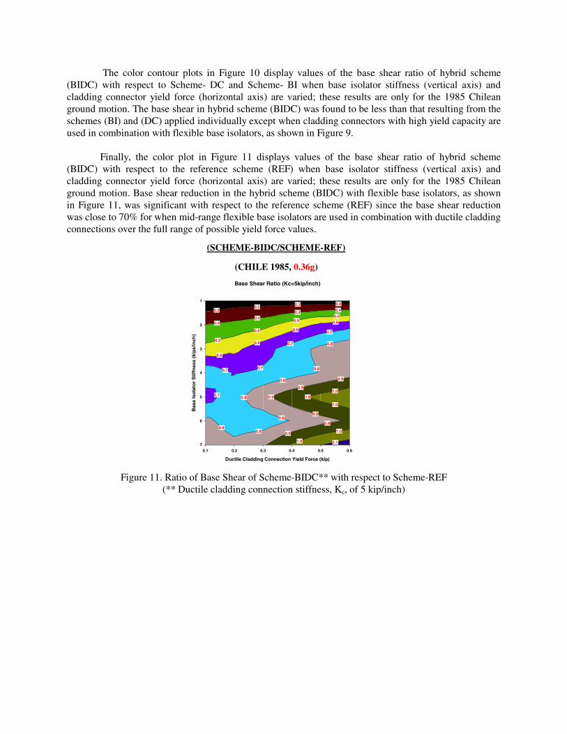
Finally, the color plot in Figure 11 displays values of the base shear ratio of hybrid scheme
(BIDC) with respect to the reference scheme (REF) when base isolator stiffness (vertical axis) and cladding connector yield force (horizontal axis) are varied; these results are only for the 1985 Chilean ground motion. Base shear reduction in the hybrid scheme (BIDC) with flexible base isolators, as shown in Figure 11, was significant with respect to the reference scheme (REF) since the base shear reduction was close to 70% for when mid-range flexible base isolators are used in combination with ductile cladding connections over the full range of possible yield force values.
Figure 11. Ratio of Base Shear of Scheme-BIDC** with respect to Scheme-REF
(** Ductile cladding connection stiffness, Kc, of 5 kip/inch)
(SCHEME-BIDC/SCHEME-REF)
Base Shear Ratio (Kc=5kip/inch)
Ductile Cladding Connection Yield Force (kip)
0.1 0.2 0.3 0.4 0.5 0.6
Bas
e Is
olat
or
Stif
fnes
s (k
ips/
inch
)
1
2
3
4
5
6
71.1
1.0
1.0
1.0
1.0
0.9
0.9
0.8
0.8
0.8
0.7 0.7
0.7
0.7
0.6
0.6
0.6
0.6
0.5
0.5
0.50.5
0.40.4
0.4 0.40.30.3
0.3 0.3
0.9
0.9
0.9
1.00.9
0.80.8
0.8
0.80.7
(CHILE 1985, 0.36g)

CONCLUSIONS AND FUTURE RESEARCH
These preliminary studies have shown that properly designed advanced ductile cladding connectors are capable of providing significant levels of performance improvement, in terms of either enhanced serviceability (e.g., reduced peak displacements, accelerations) or reduced seismic demand on the primary structure. Ductile connectors can be combined with base isolation systems to further improve energy dissipation capabilities throughout the structure and to also decrease peak inter-story drift. Properly selected combinations of base isolators and advanced ductile cladding connections will provide performance improvements based on different performance measures such as reduction in base shear and overturning moment, earthquake input energy and ductility demand in frame members. These combination schemes are expected to be effective if applied to buildings such as mid-rise and high-rise steel framed structures and may provide better performance than that resulting from the methods applied individually to achieve reductions in peak base shear and earthquake input energy.
Parameter studies are continuing and will explore other measures such as the effect of nonlinear
base isolators, the ratio of panel mass to floor mass, and the ratio of base isolator stiffness to global structure stiffness for ductile cladding connection designs used throughout the structure. Finally, these studies will be extended to the 3 and 9 story SAC buildings and a broader range of representative ground motions in order to validate the hybrid passive energy dissipation concept presented in this paper.

REFERENCES 1. Blanchet, C., Craig, J. I., and Goodno, B. J. (1998). “Experimental Evaluation of Advanced
Ductile Cladding Connector Designs for Passive Seismic Response Attenuation in Buildings,” Proceedings, Sixth U.S. National Conference on Earthquake Engineering Research, Paper 320 on CDROM, Seattle, May 31-June 4.
2. Goodno, B. J., Craig, J. I., Dogan, T., and Towashiraporn, P. (1998), “Ductile Cladding
Connection Systems for Seismic Design,” Building and Fire Research Laboratory, NIST, Report GCR 98-758.
3. Pinelli, J. P., Moor, C., Craig, J. I., and Goodno, B. J. (1992a). “Experimental Testing of Ductile
Cladding Connections for Building Facades,” International Journal of the Structural Design of Tall Buildings, John Wiley and Sons, Inc., Vol. 1, No. 1, October, 57-72.
4. Pinelli, J. P. (1992b). “Development of Energy Dissipating Cladding Connections for Passive
Control of Building Seismic Response.” Ph.D. dissertation, School of Civil Engineering, Georgia Institute of Technology, Atlanta, Georgia, November.
5. Pinelli, J. P., Craig, J. I., Goodno, B. J., and Hsu, C. C. (1993), “Passive Control of Building
Response Using Energy Dissipating Cladding Connections,” Earthquake Spectra, Vol. 9, No. 3, pp. 529-546.
6. Pinelli, J. P., Moor, C., Craig, J. I., and Goodno, B. J. (1996), “Testing of Energy Dissipating
Cladding Connections,” Earthquake Engineering and Structural Dynamics, Vol. 25, pp. 129-147. 7. Prakash, V., Powell, G. H., and Campbell, S. (1993), “DRAIN-2DX Base Program Description
and User Guide,” Version 1.10, Dept. of Civil Engineering, University of California Berkeley, November.
8. Powell, G. H. (2000), “RAM Perform 2D User's Guide,” RAM International, 5315 Avenida
Encinas, Suite 220, Carlsbad, California 92008. 9. Reinhorn, A. M., Soong, T., Lin, R. C. and Wang, Y.P. (1989), “1:4 Scale Model Studies of Active
Tendon Systems and Active Mass Dampers for Aseismic Protection,” Report NCEER-89-0026, National Center for Earthquake Engineering Research, SUNY, Buffalo, New York.
10. Uniform Building Code. (1991), International Conference of Buildings Officials, 5360 S.
Workman Mill Rd., Whittier, CA, 90602, 1991.