hybrid structure solution for the a400m wing attachment...
TRANSCRIPT

Matthijs Plokker / Derk Daverschot - ICAF 2009
20/05/2009
Hybrid structure solution for the A400M wing attachment frames
From concept study to structural justification
ICAF 2009, Rotterdam
Presented by
Matthijs Plokker / Derk DaverschotFatigue and Damage Tolerance, Airbus
20/05/2009Matthijs Plokker / Derk Daverschot - ICAF 2009 Page 2© A
IRB
US
DE
UTS
CH
LAN
D G
MBH
. A
ll rig
hts
rese
rved
. Con
fiden
tial a
nd p
ropr
ieta
ry d
ocum
ent.
Contents
• Introduction A400M – GeneralProblem description
• Concept study
• ImplementationDesign & MaterialProduction ProcessQuality Assurance
• Structural QualificationRequirementsAnalysisTest

20/05/2009Matthijs Plokker / Derk Daverschot - ICAF 2009 Page 3© A
IRB
US
DE
UTS
CH
LAN
D G
MBH
. A
ll rig
hts
rese
rved
. Con
fiden
tial a
nd p
ropr
ieta
ry d
ocum
ent.
A400M – General
A400M General Configuration
Typical for A400M and deviating from common Airbus A/C:
•Turboprop engines
•High wing
•T-tail
•MLG configuration
•Cargo Ramp & Door
•Militairy Systems:
Cargo Handling system, AAR
20/05/2009Matthijs Plokker / Derk Daverschot - ICAF 2009 Page 4© A
IRB
US
DE
UTS
CH
LAN
D G
MBH
. A
ll rig
hts
rese
rved
. Con
fiden
tial a
nd p
ropr
ieta
ry d
ocum
ent.
A400M – General
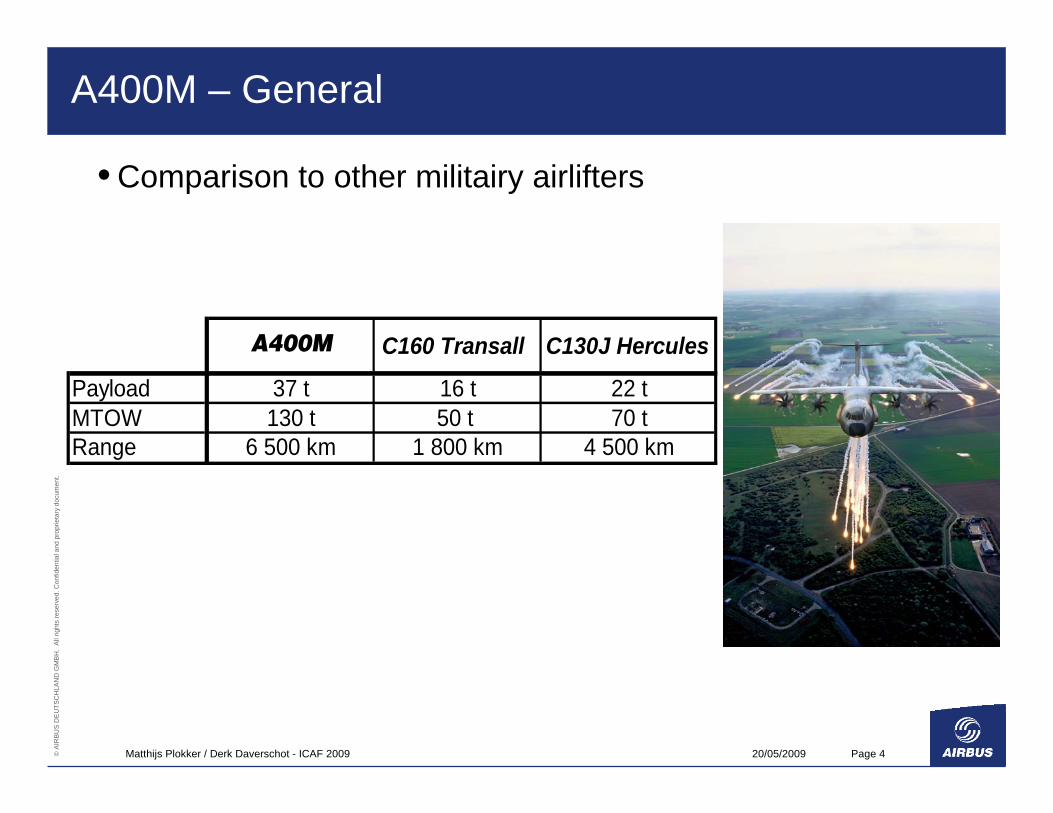
• Comparison to other militairy airlifters
A400M C160 Transall C130J Hercules
Payload 37 t 16 t 22 tMTOW 130 t 50 t 70 tRange 6 500 km 1 800 km 4 500 km

20/05/2009Matthijs Plokker / Derk Daverschot - ICAF 2009 Page 5© A
IRB
US
DE
UTS
CH
LAN
D G
MBH
. A
ll rig
hts
rese
rved
. Con
fiden
tial a
nd p
ropr
ieta
ry d
ocum
ent.
A400M – General
• Comparison to „other airlifters“
length [m] 45 59wingspan [m] 42 60height [m] 15 17
A400M C160 Transall C130J Hercules A330-200F
Payload 37 t 16 t 22 t 69 tMTOW 130 t 50 t 70 t 228 tRange 6 500 km 1 800 km 4 500 km 7 400 km
20/05/2009Matthijs Plokker / Derk Daverschot - ICAF 2009 Page 6© A
IRB
US
DE
UTS
CH
LAN
D G
MBH
. A
ll rig
hts
rese
rved
. Con
fiden
tial a
nd p
ropr
ieta
ry d
ocum
ent.
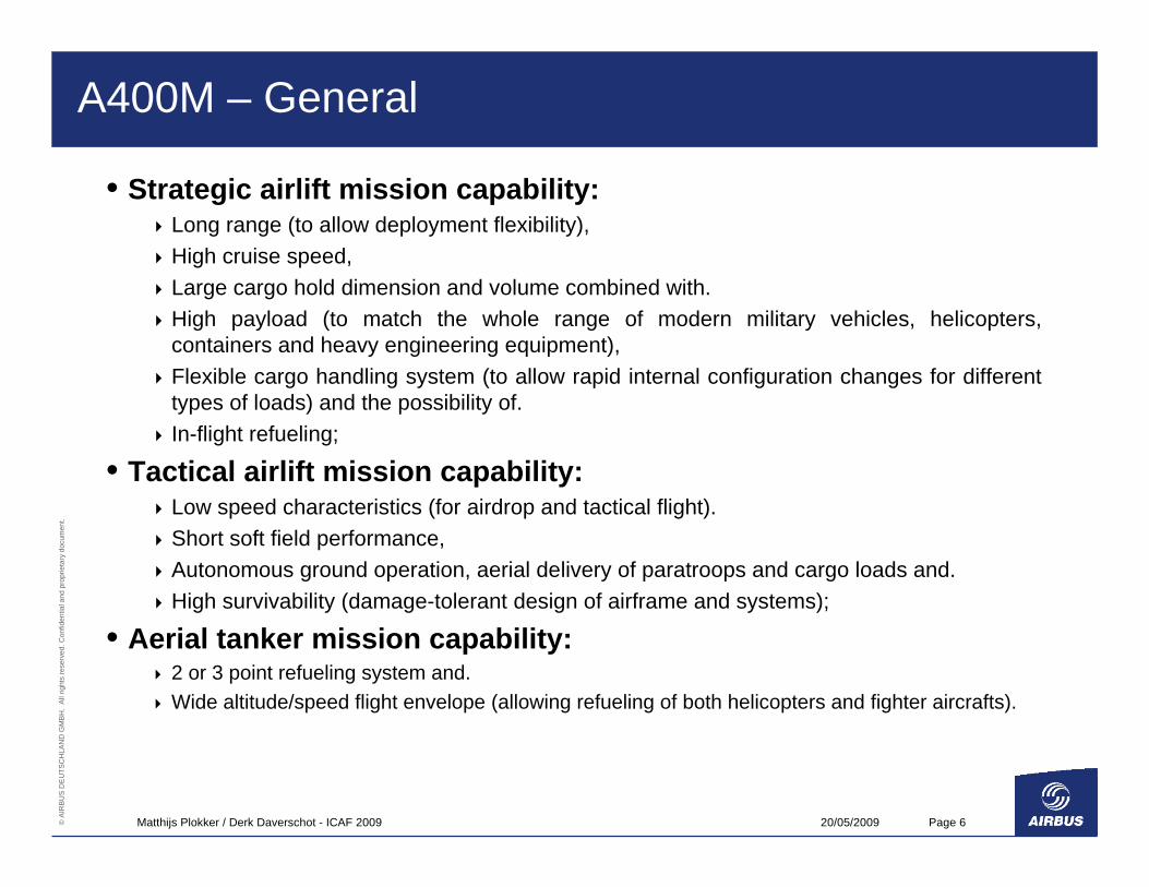
A400M – General
• Strategic airlift mission capability:Long range (to allow deployment flexibility),High cruise speed,Large cargo hold dimension and volume combined with.High payload (to match the whole range of modern military vehicles, helicopters, containers and heavy engineering equipment),Flexible cargo handling system (to allow rapid internal configuration changes for different types of loads) and the possibility of.In-flight refueling;
• Tactical airlift mission capability:Low speed characteristics (for airdrop and tactical flight).Short soft field performance,Autonomous ground operation, aerial delivery of paratroops and cargo loads and.High survivability (damage-tolerant design of airframe and systems);
• Aerial tanker mission capability:2 or 3 point refueling system and.Wide altitude/speed flight envelope (allowing refueling of both helicopters and fighter aircrafts).
20/05/2009Matthijs Plokker / Derk Daverschot - ICAF 2009 Page 7© A
IRB
US
DE
UTS
CH
LAN
D G
MBH
. A
ll rig
hts
rese
rved
. Con
fiden
tial a
nd p
ropr
ieta
ry d
ocum
ent.
A400M – General
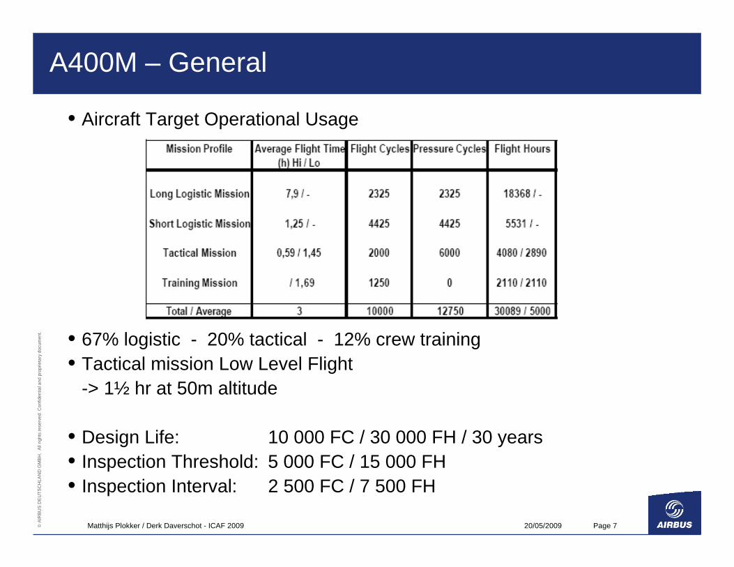
• Aircraft Target Operational Usage
• 67% logistic - 20% tactical - 12% crew training• Tactical mission Low Level Flight
-> 1½ hr at 50m altitude
• Design Life: 10 000 FC / 30 000 FH / 30 years• Inspection Threshold: 5 000 FC / 15 000 FH• Inspection Interval: 2 500 FC / 7 500 FH
20/05/2009Matthijs Plokker / Derk Daverschot - ICAF 2009 Page 8© A
IRB
US
DE
UTS
CH
LAN
D G
MBH
. A
ll rig
hts
rese
rved
. Con
fiden
tial a
nd p
ropr
ieta
ry d
ocum
ent.
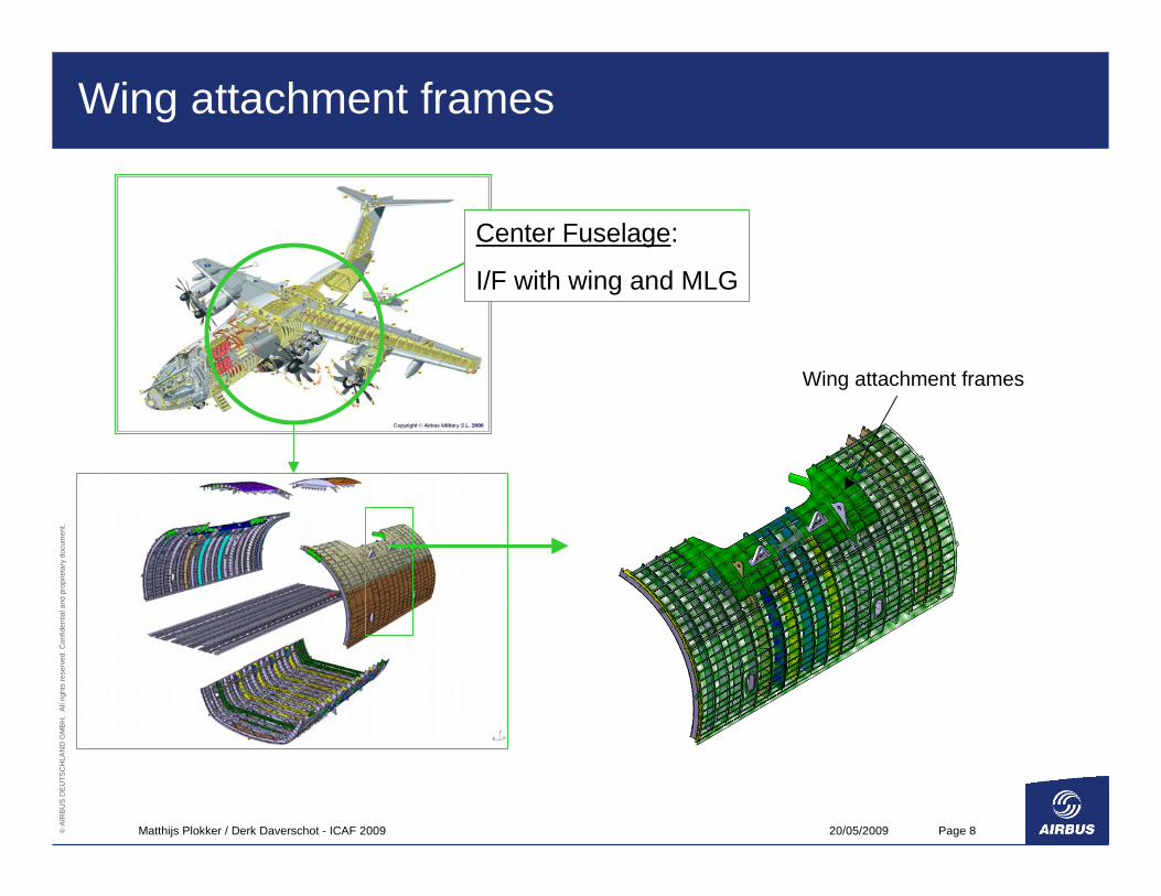
Wing attachment frames
Center Fuselage:
I/F with wing and MLG
Wing attachment frames
20/05/2009Matthijs Plokker / Derk Daverschot - ICAF 2009 Page 9© A
IRB
US
DE
UTS
CH
LAN
D G
MBH
. A
ll rig
hts
rese
rved
. Con
fiden
tial a
nd p
ropr
ieta
ry d
ocum
ent.
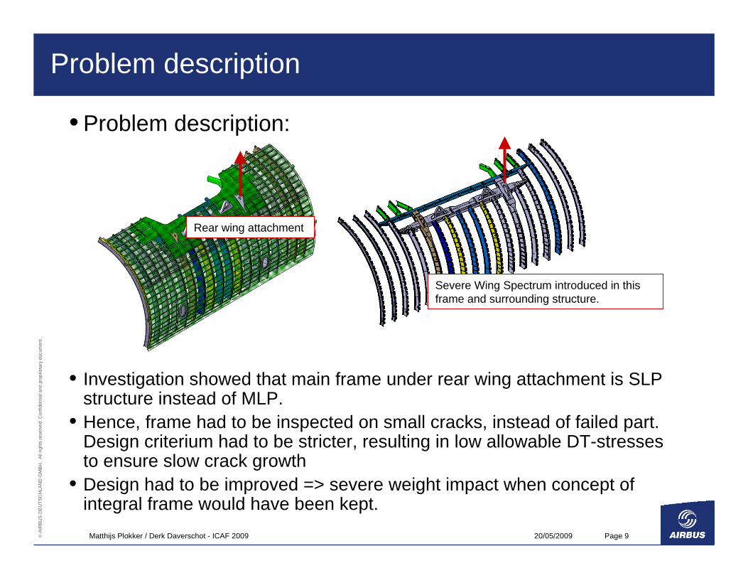
Problem description
• Problem description:
• Investigation showed that main frame under rear wing attachment is SLP structure instead of MLP.
• Hence, frame had to be inspected on small cracks, instead of failed part. Design criterium had to be stricter, resulting in low allowable DT-stressesto ensure slow crack growth
• Design had to be improved => severe weight impact when concept of integral frame would have been kept.
Rear wing attachment
Severe Wing Spectrum introduced in this frame and surrounding structure.
20/05/2009Matthijs Plokker / Derk Daverschot - ICAF 2009 Page 10© A
IRB
US
DE
UTS
CH
LAN
D G
MBH
. A
ll rig
hts
rese
rved
. Con
fiden
tial a
nd p
ropr
ieta
ry d
ocum
ent.
Problem description
• Wing spectrum caused in frame inner flange below rear wing attachment:
1. High Fatigue Stresses in inner flange2. High tensional static loads
• Resulting in:1. To meet inspection interval detecable crack length 1-2 mm
– Risk due to low probability of detection2. Critical crack length is extremely small (enhanced by brittle alloy)
• Risk on Multiple Element Damage (MED) due to similar high stress level in neighbouring frames
20/05/2009Matthijs Plokker / Derk Daverschot - ICAF 2009 Page 11© A
IRB
US
DE
UTS
CH
LAN
D G
MBH
. A
ll rig
hts
rese
rved
. Con
fiden
tial a
nd p
ropr
ieta
ry d
ocum
ent.
Concept study
• Study was carried out on improvement of the main frame looking at:Safety (Inspectibility, DT-behaviour)WeightCost
• 3 options were investigated:1. Thickening of the aluminium inner flange to reach an acceptable stress
level.2. Riveted Titanium strap attached to the inner flange.3. FML strap adhesively bonded to the inner flange.
20/05/2009Matthijs Plokker / Derk Daverschot - ICAF 2009 Page 12© A
IRB
US
DE
UTS
CH
LAN
D G
MBH
. A
ll rig
hts
rese
rved
. Con
fiden
tial a
nd p
ropr
ieta
ry d
ocum
ent.
Concept study
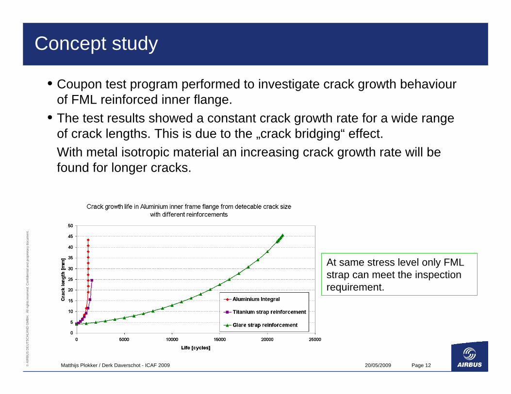
• Coupon test program performed to investigate crack growth behaviourof FML reinforced inner flange.
• The test results showed a constant crack growth rate for a wide rangeof crack lengths. This is due to the „crack bridging“ effect.With metal isotropic material an increasing crack growth rate will be found for longer cracks.
At same stress level only FML strap can meet the inspection requirement.
20/05/2009Matthijs Plokker / Derk Daverschot - ICAF 2009 Page 13© A
IRB
US
DE
UTS
CH
LAN
D G
MBH
. A
ll rig
hts
rese
rved
. Con
fiden
tial a
nd p
ropr
ieta
ry d
ocum
ent.
Concept study - FML strap
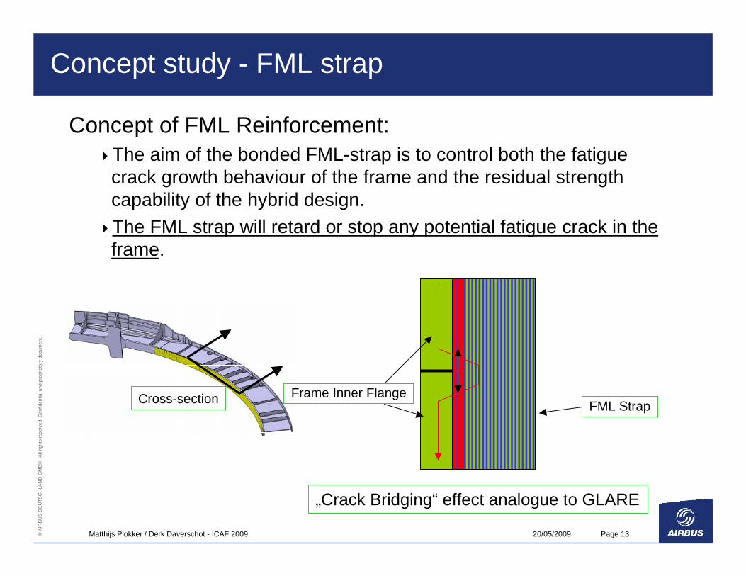
Concept of FML Reinforcement:The aim of the bonded FML-strap is to control both the fatigue crack growth behaviour of the frame and the residual strength capability of the hybrid design. The FML strap will retard or stop any potential fatigue crack in the frame.
Frame Inner FlangeFML Strap
„Crack Bridging“ effect analogue to GLARE
Cross-section
20/05/2009Matthijs Plokker / Derk Daverschot - ICAF 2009 Page 14© A
IRB
US
DE
UTS
CH
LAN
D G
MBH
. A
ll rig
hts
rese
rved
. Con
fiden
tial a
nd p
ropr
ieta
ry d
ocum
ent.
Concept study - Conclusions
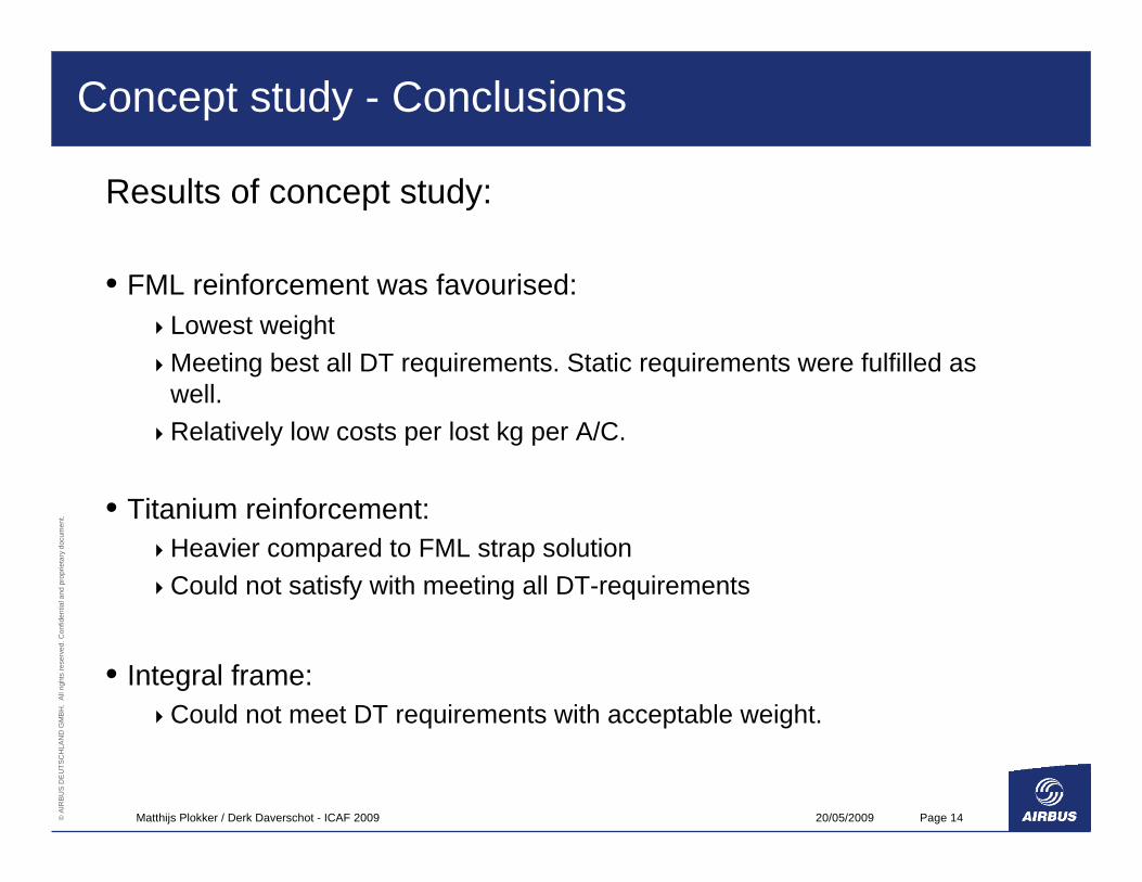
Results of concept study:
• FML reinforcement was favourised:Lowest weightMeeting best all DT requirements. Static requirements were fulfilled as well.Relatively low costs per lost kg per A/C.
• Titanium reinforcement:Heavier compared to FML strap solutionCould not satisfy with meeting all DT-requirements
• Integral frame:Could not meet DT requirements with acceptable weight.

20/05/2009Matthijs Plokker / Derk Daverschot - ICAF 2009 Page 15© A
IRB
US
DE
UTS
CH
LAN
D G
MBH
. A
ll rig
hts
rese
rved
. Con
fiden
tial a
nd p
ropr
ieta
ry d
ocum
ent.
Concept study - Conclusions
--Integral Aluminium
++++FML Strap
--+Titanium Strap
Effort to detect cracks
Weight opportunity
Option
20/05/2009Matthijs Plokker / Derk Daverschot - ICAF 2009 Page 16© A
IRB
US
DE
UTS
CH
LAN
D G
MBH
. A
ll rig
hts
rese
rved
. Con
fiden
tial a
nd p
ropr
ieta
ry d
ocum
ent.
Concept study - Conclusions
• In general the FML reinforcement bonded application is a solution for structural parts that are highly loaded under tension. Without FML-reinforcement this structural part would be a SLP or a structure with poor damage containment feature at the most.
• Bonded FML-reinforcement is normally optimal for SLP frames, regarding:
1. Safety -> larger critical crack length, reducing risk of MED.2. Weight -> Higher Allowable Stresses for DT 3. Cost -> Less inspection with lower inspection level
20/05/2009Matthijs Plokker / Derk Daverschot - ICAF 2009 Page 17© A
IRB
US
DE
UTS
CH
LAN
D G
MBH
. A
ll rig
hts
rese
rved
. Con
fiden
tial a
nd p
ropr
ieta
ry d
ocum
ent.
Implementation - Design & Material
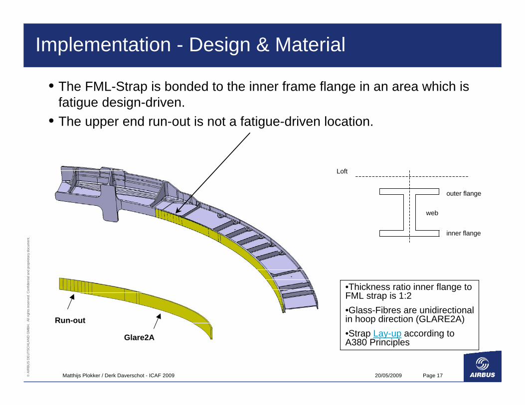
• The FML-Strap is bonded to the inner frame flange in an area which is fatigue design-driven.
• The upper end run-out is not a fatigue-driven location.
Run-out
Glare2A
•Thickness ratio inner flange to FML strap is 1:2•Glass-Fibres are unidirectional in hoop direction (GLARE2A)•Strap Lay-up according to A380 Principles
Loft
web
inner flange
outer flange
20/05/2009Matthijs Plokker / Derk Daverschot - ICAF 2009 Page 18© A
IRB
US
DE
UTS
CH
LAN
D G
MBH
. A
ll rig
hts
rese
rved
. Con
fiden
tial a
nd p
ropr
ieta
ry d
ocum
ent.
Implementation - Design & Material
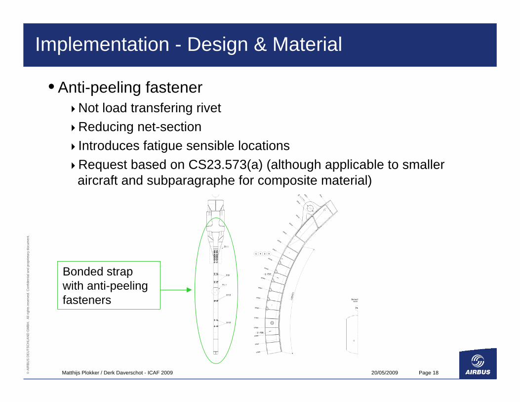
• Anti-peeling fastener Not load transfering rivetReducing net-sectionIntroduces fatigue sensible locationsRequest based on CS23.573(a) (although applicable to smaller aircraft and subparagraphe for composite material)
Bonded strap with anti-peeling fasteners
20/05/2009Matthijs Plokker / Derk Daverschot - ICAF 2009 Page 19© A
IRB
US
DE
UTS
CH
LAN
D G
MBH
. A
ll rig
hts
rese
rved
. Con
fiden
tial a
nd p
ropr
ieta
ry d
ocum
ent.
Implementation - Design & Material
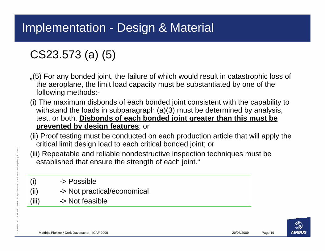
CS23.573 (a) (5)
„(5) For any bonded joint, the failure of which would result in catastrophic loss of the aeroplane, the limit load capacity must be substantiated by one of the following methods:-
(i) The maximum disbonds of each bonded joint consistent with the capability to withstand the loads in subparagraph (a)(3) must be determined by analysis, test, or both. Disbonds of each bonded joint greater than this must be prevented by design features; or
(ii) Proof testing must be conducted on each production article that will apply the critical limit design load to each critical bonded joint; or
(iii) Repeatable and reliable nondestructive inspection techniques must be established that ensure the strength of each joint.“
(i) -> Possible(ii) -> Not practical/economical(iii) -> Not feasible
20/05/2009Matthijs Plokker / Derk Daverschot - ICAF 2009 Page 20© A
IRB
US
DE
UTS
CH
LAN
D G
MBH
. A
ll rig
hts
rese
rved
. Con
fiden
tial a
nd p
ropr
ieta
ry d
ocum
ent.
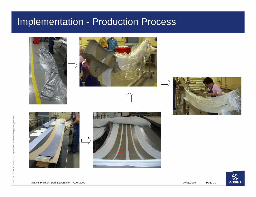
Implementation - Production Process
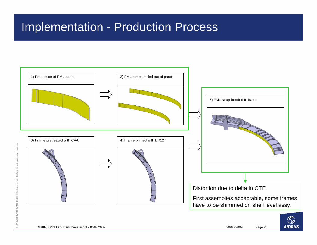
2) FML-straps milled out of panel 1) Production of FML-panel
5) FML-strap bonded to frame
3) Frame pretreated with CAA 4) Frame primed with BR127
Distortion due to delta in CTE
First assemblies acceptable, some frames have to be shimmed on shell level assy.
20/05/2009Matthijs Plokker / Derk Daverschot - ICAF 2009 Page 21© A
IRB
US
DE
UTS
CH
LAN
D G
MBH
. A
ll rig
hts
rese
rved
. Con
fiden
tial a
nd p
ropr
ieta
ry d
ocum
ent.
Implementation - Production Process
20/05/2009Matthijs Plokker / Derk Daverschot - ICAF 2009 Page 22© A
IRB
US
DE
UTS
CH
LAN
D G
MBH
. A
ll rig
hts
rese
rved
. Con
fiden
tial a
nd p
ropr
ieta
ry d
ocum
ent.
Implementation - Quality Assurance
Inspection during manufacturing:Step 1: Manufacturing of FML-strap laminateInspection of the laminate by ultrasonic through transmission in squirter technique
Step 2: Bonding of FML-strap to Aluminium frameInspection of bond line by manual ultrasonic through transmission technique
20/05/2009Matthijs Plokker / Derk Daverschot - ICAF 2009 Page 23© A
IRB
US
DE
UTS
CH
LAN
D G
MBH
. A
ll rig
hts
rese
rved
. Con
fiden
tial a
nd p
ropr
ieta
ry d
ocum
ent.
Implementation - Quality Assurance
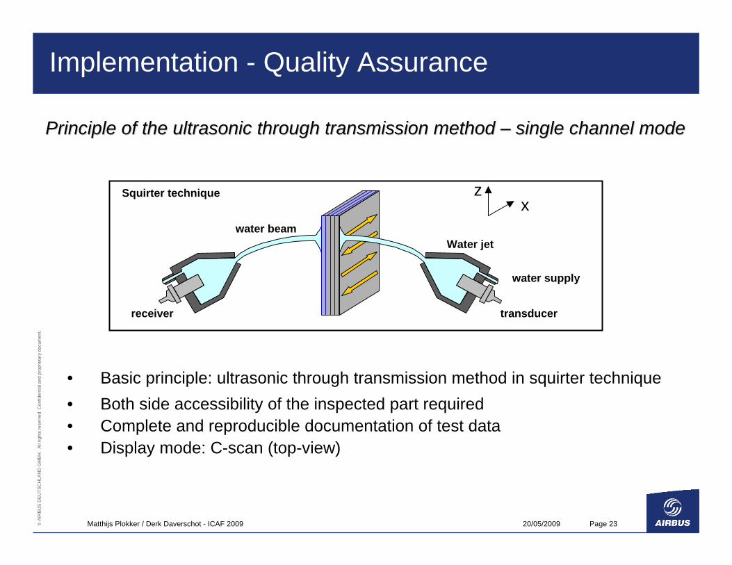
Principle of the ultrasonic through transmission method Principle of the ultrasonic through transmission method –– single channel modesingle channel mode
water beamWater jet
water supply
transducerreceiver
Squirter techniquex
z
• Basic principle: ultrasonic through transmission method in squirter technique• Both side accessibility of the inspected part required• Complete and reproducible documentation of test data• Display mode: C-scan (top-view)
20/05/2009Matthijs Plokker / Derk Daverschot - ICAF 2009 Page 24© A
IRB
US
DE
UTS
CH
LAN
D G
MBH
. A
ll rig
hts
rese
rved
. Con
fiden
tial a
nd p
ropr
ieta
ry d
ocum
ent.
Implementation - Quality Assurance
Principle of the ultrasonic through transmission method Principle of the ultrasonic through transmission method –– single channel modesingle channel mode
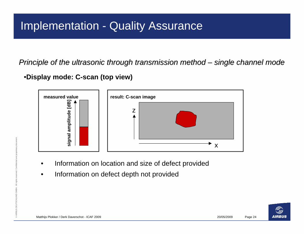
• Information on location and size of defect provided• Information on defect depth not provided
sign
al a
mpl
itude
[dB
]measured value result: C-scan image
x
z
•Display mode: C-scan (top view)
20/05/2009Matthijs Plokker / Derk Daverschot - ICAF 2009 Page 25© A
IRB
US
DE
UTS
CH
LAN
D G
MBH
. A
ll rig
hts
rese
rved
. Con
fiden
tial a
nd p
ropr
ieta
ry d
ocum
ent.
Implementation - Quality Assurance
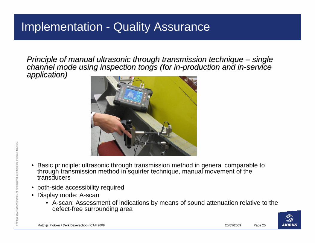
Principle of manual ultrasonic through transmission technique Principle of manual ultrasonic through transmission technique –– single single channel mode using inspection tongs (for inchannel mode using inspection tongs (for in--production and inproduction and in--service service application)application)
• Basic principle: ultrasonic through transmission method in general comparable to through transmission method in squirter technique, manual movement of the transducers
• both-side accessibility required • Display mode: A-scan
• A-scan: Assessment of indications by means of sound attenuation relative to the defect-free surrounding area
20/05/2009Matthijs Plokker / Derk Daverschot - ICAF 2009 Page 26© A
IRB
US
DE
UTS
CH
LAN
D G
MBH
. A
ll rig
hts
rese
rved
. Con
fiden
tial a
nd p
ropr
ieta
ry d
ocum
ent.
Structural Qualification - Requirements
Basis for Certification
• JCRI (JAA Certification Review Item) is a selected identified item of thecivil CS regulation with rules and policies established in other civil programs.
• MCRI (Military Certification Review Item) is a selected extension of thecivil CS regulation with rules and policies derived from military regulations and standards.
• Note: Although A400M is a militairy transport aircraft, the basis for certification is the civil CS25 – former JAR25.
Hence CS25.571 (b) is applicable, which implies requirement of Damage Tolerant design.

20/05/2009Matthijs Plokker / Derk Daverschot - ICAF 2009 Page 27© A
IRB
US
DE
UTS
CH
LAN
D G
MBH
. A
ll rig
hts
rese
rved
. Con
fiden
tial a
nd p
ropr
ieta
ry d
ocum
ent.
Structural Qualification - Analysis
• Main Frame with FML-Strap is a Structure with DamageContainment Feature (DCF).
• Calculated ComponentsJustification of FML strap (run-out and highest stressed location)Justification of Frame Inner Flange
• Failure CriteriaF&DT: Fatigue, Crack Growth, No Defect Growth, Residual Strength.Static: Material Strength, Stability
Analyses supported by Test Evidence
20/05/2009Matthijs Plokker / Derk Daverschot - ICAF 2009 Page 28© A
IRB
US
DE
UTS
CH
LAN
D G
MBH
. A
ll rig
hts
rese
rved
. Con
fiden
tial a
nd p
ropr
ieta
ry d
ocum
ent.
Structural Qualification - Analysis
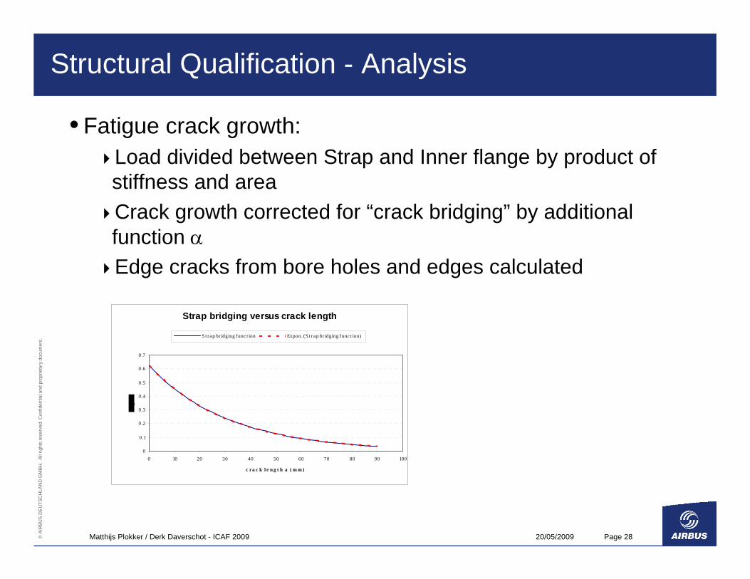
• Fatigue crack growth:Load divided between Strap and Inner flange by product of stiffness and areaCrack growth corrected for “crack bridging” by additional function αEdge cracks from bore holes and edges calculated
Strap bridging versus crack length
0
0.1
0.2
0.3
0.4
0.5
0.6
0.7
0 10 20 30 40 50 60 70 80 90 100
c r a c k l e n g t h a ( m m )
S t ra p br idging func t ion Expon. (S t ra p br idging func t ion)
20/05/2009Matthijs Plokker / Derk Daverschot - ICAF 2009 Page 29© A
IRB
US
DE
UTS
CH
LAN
D G
MBH
. A
ll rig
hts
rese
rved
. Con
fiden
tial a
nd p
ropr
ieta
ry d
ocum
ent.
Structural Qualification - Analysis
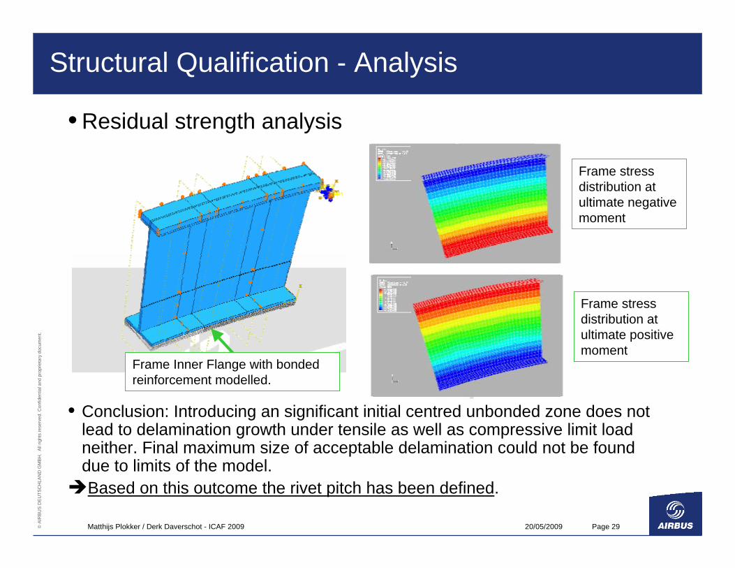
• Residual strength analysis
• Conclusion: Introducing an significant initial centred unbonded zone does not lead to delamination growth under tensile as well as compressive limit load neither. Final maximum size of acceptable delamination could not be found due to limits of the model.Based on this outcome the rivet pitch has been defined.
Frame stress distribution at ultimate positive moment
Frame stress distribution at ultimate negative moment
Frame Inner Flange with bonded reinforcement modelled.

20/05/2009Matthijs Plokker / Derk Daverschot - ICAF 2009 Page 30© A
IRB
US
DE
UTS
CH
LAN
D G
MBH
. A
ll rig
hts
rese
rved
. Con
fiden
tial a
nd p
ropr
ieta
ry d
ocum
ent.
Structural Qualification - Test
• Full-scale Fatigue Test with MSN5001
• Frames on Left Hand (LH) and Right Hand (RH) with FML straps:LH side: normal series standardRH side: small artificial delaminations in frame-strap bondline and Glare
• Simulating 2.5 DSG (25.000 FC)Planned for Feb. 2010- Feb. 2011
20/05/2009Matthijs Plokker / Derk Daverschot - ICAF 2009 Page 31© A
IRB
US
DE
UTS
CH
LAN
D G
MBH
. A
ll rig
hts
rese
rved
. Con
fiden
tial a
nd p
ropr
ieta
ry d
ocum
ent.
Structural Qualification - Test
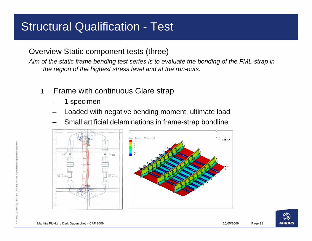
Overview Static component tests (three)Aim of the static frame bending test series is to evaluate the bonding of the FML-strap in
the region of the highest stress level and at the run-outs.
1. Frame with continuous Glare strap– 1 specimen – Loaded with negative bending moment, ultimate load– Small artificial delaminations in frame-strap bondline
20/05/2009Matthijs Plokker / Derk Daverschot - ICAF 2009 Page 32© A
IRB
US
DE
UTS
CH
LAN
D G
MBH
. A
ll rig
hts
rese
rved
. Con
fiden
tial a
nd p
ropr
ieta
ry d
ocum
ent.
Structural Qualification - Test
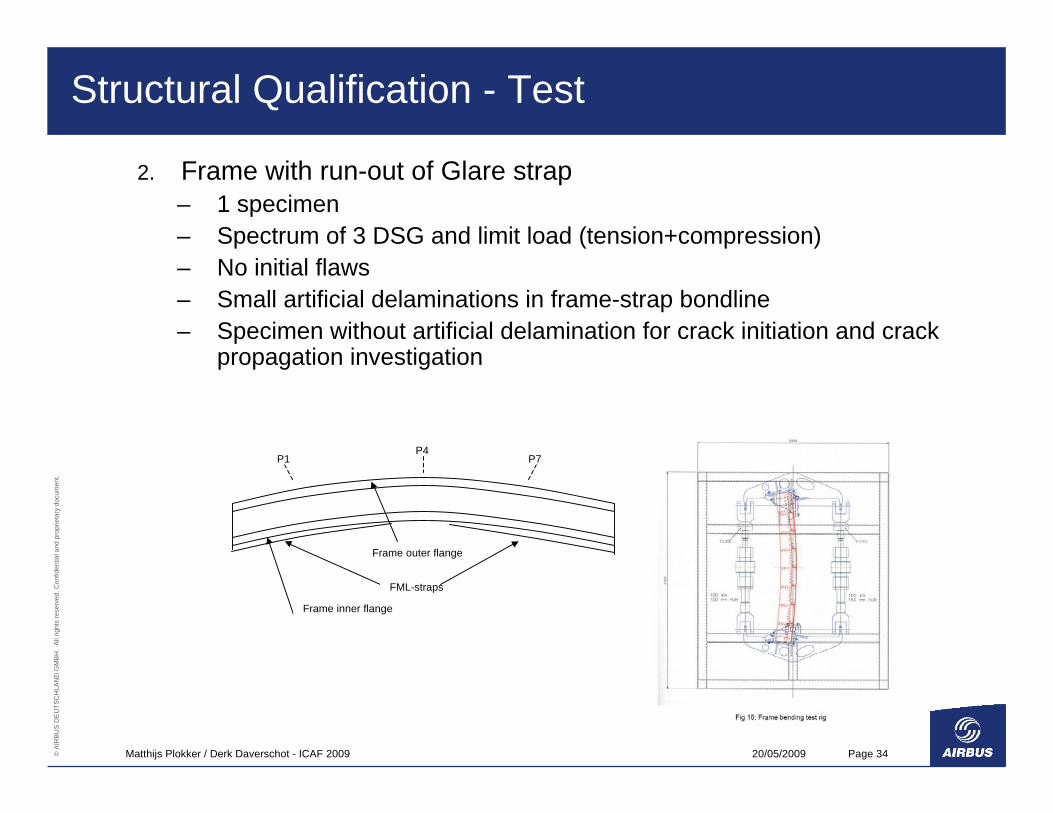
2. Frame with run-out of Glare strap, – 2 specimens– Loaded with positive/negative bending moment, ultimate load– Small artificial delaminations in frame-strap bondline
3. Frame with continuous Glare strap – 2 specimens– Loaded with positive/negative bending moment, limit load– Large artificial delamination in frame-strap bondline (determined from
FE-analysis)
20/05/2009Matthijs Plokker / Derk Daverschot - ICAF 2009 Page 33© A
IRB
US
DE
UTS
CH
LAN
D G
MBH
. A
ll rig
hts
rese
rved
. Con
fiden
tial a
nd p
ropr
ieta
ry d
ocum
ent.
Structural Qualification - Test
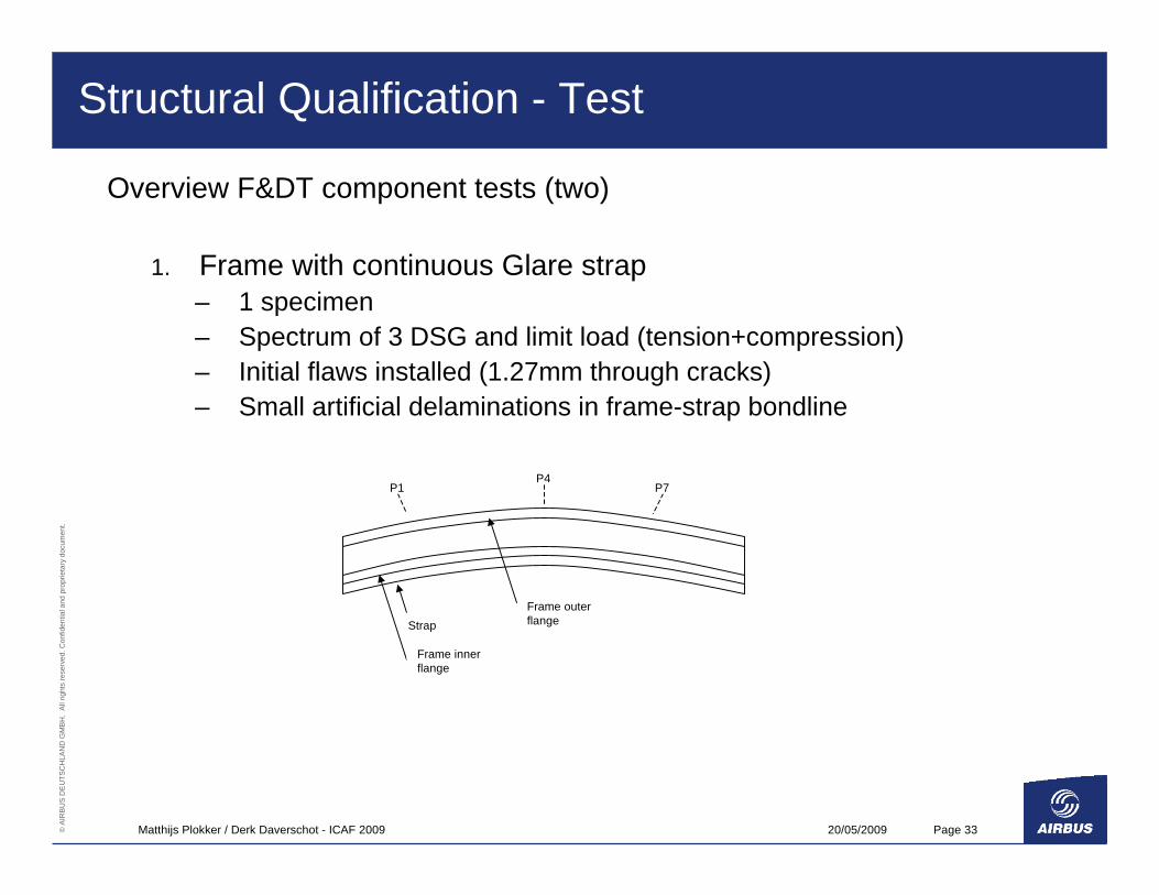
Overview F&DT component tests (two)
1. Frame with continuous Glare strap– 1 specimen– Spectrum of 3 DSG and limit load (tension+compression)– Initial flaws installed (1.27mm through cracks) – Small artificial delaminations in frame-strap bondline
Strap
Frame inner flange
Frame outer flange
P4P7P1
20/05/2009Matthijs Plokker / Derk Daverschot - ICAF 2009 Page 34© A
IRB
US
DE
UTS
CH
LAN
D G
MBH
. A
ll rig
hts
rese
rved
. Con
fiden
tial a
nd p
ropr
ieta
ry d
ocum
ent.
Structural Qualification - Test
2. Frame with run-out of Glare strap– 1 specimen– Spectrum of 3 DSG and limit load (tension+compression)– No initial flaws– Small artificial delaminations in frame-strap bondline– Specimen without artificial delamination for crack initiation and crack
propagation investigation
FML-straps
Frame inner flange
Frame outer flange
P4P7P1
20/05/2009Matthijs Plokker / Derk Daverschot - ICAF 2009 Page 35© A
IRB
US
DE
UTS
CH
LAN
D G
MBH
. A
ll rig
hts
rese
rved
. Con
fiden
tial a
nd p
ropr
ieta
ry d
ocum
ent.
Structural Qualification - Test
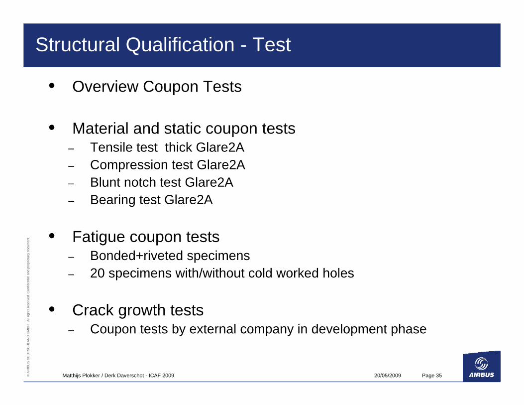
• Overview Coupon Tests
• Material and static coupon tests – Tensile test thick Glare2A – Compression test Glare2A– Blunt notch test Glare2A – Bearing test Glare2A
• Fatigue coupon tests– Bonded+riveted specimens– 20 specimens with/without cold worked holes
• Crack growth tests – Coupon tests by external company in development phase
20/05/2009Matthijs Plokker / Derk Daverschot - ICAF 2009 Page 36© A
IRB
US
DE
UTS
CH
LAN
D G
MBH
. A
ll rig
hts
rese
rved
. Con
fiden
tial a
nd p
ropr
ieta
ry d
ocum
ent.
Summary
• FML strap establishes a safer, damage tolerant design of a highly loaded frame.
• The new application has been introduced with an extensive qualification program. All disciplines have to coorperate closely.
Structure engineering MaterialQuality AssuranceProcess
• The first Production and Assembly has been succesfull.
20/05/2009Matthijs Plokker / Derk Daverschot - ICAF 2009 Page 37© A
IRB
US
DE
UTS
CH
LAN
D G
MBH
. A
ll rig
hts
rese
rved
. Con
fiden
tial a
nd p
ropr
ieta
ry d
ocum
ent.
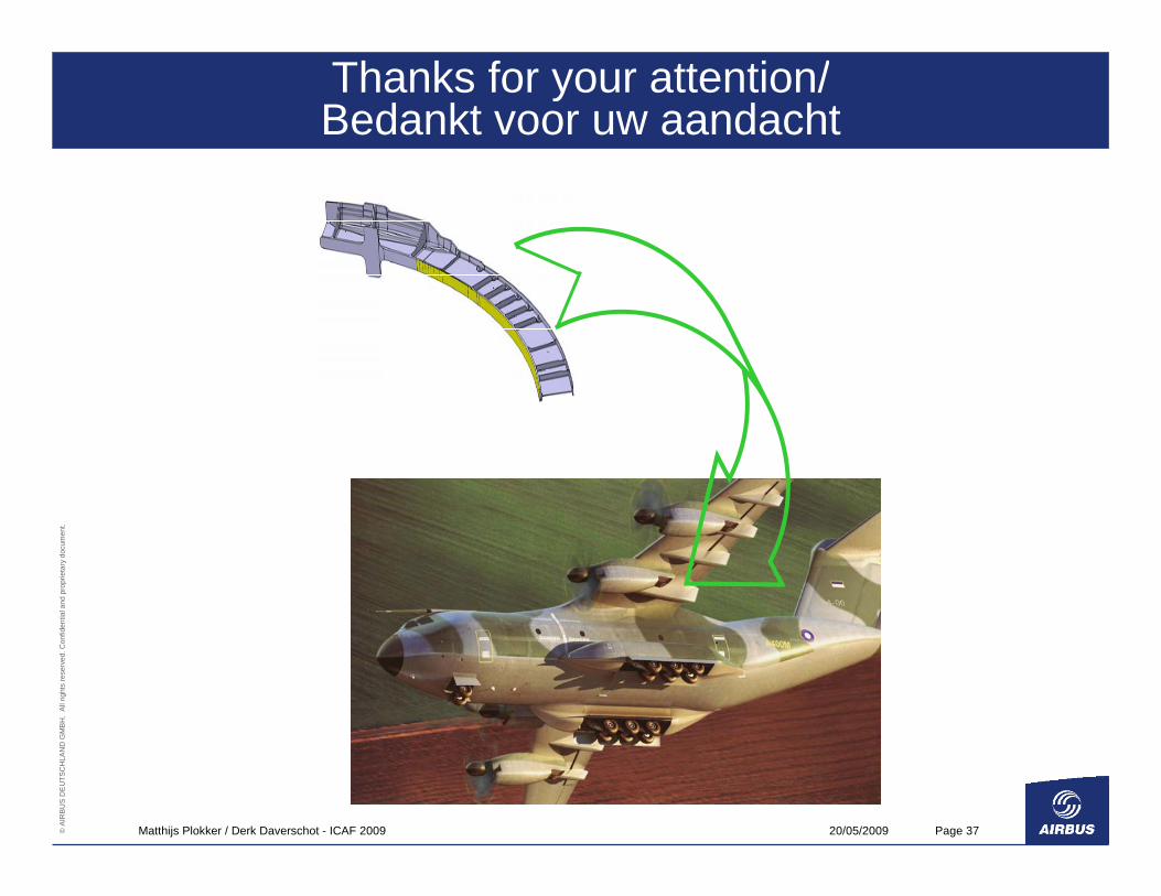
Thanks for your attention/Bedankt voor uw aandacht

20/05/2009Matthijs Plokker / Derk Daverschot - ICAF 2009 Page 38© A
IRB
US
DE
UTS
CH
LAN
D G
MBH
. A
ll rig
hts
rese
rved
. Con
fiden
tial a
nd p
ropr
ieta
ry d
ocum
ent.
© AIRBUS DEUTSCHLAND GMBH. All rights reserved. Confidential and proprietary document.
This document and all information contained herein is the sole property of AIRBUS DEUTSCHLAND GMBH. No intellectual property rights are granted by the delivery of this document or the disclosure of its content. This document shall not be reproduced or disclosed to a third party without the express written consent of AIRBUS DEUTSCHLAND GMBH. This document and its content shall not be used for any purpose other than that for which it is supplied.
The statements made herein do not constitute an offer. They are based on the mentioned assumptions and are expressed in good faith. Where the supporting grounds for these statements are not shown, AIRBUS DEUTSCHLAND GMBH will be pleased to explain the basis thereof.
AIRBUS, its logo, A300, A310, A318, A319, A320, A321, A330, A340, A350, A380, A400M are registered trademarks.