hydraulic components steel tanks - krechina.com · hydraulic components steel tanks hydraulic...
TRANSCRIPT

155
For advanceddrive
technology
Hyd
rau
licC
om
po
nen
ts
Ste
el T
anks
HydraulicComponents
Steel Tanks

156
18 9
7
1
4
5
8
23
9
9
10
4
5
11
22
14
15
2 25 24 4 5 1 133
3145 18 9 1727 20 126 20 21 27 19 26 19
1
2
3
4
5
6
7
8
9
10
11
12
13
14
15
16
17
18
19
20
21
22
23
24
25
26
27 Tank heaters
For advanceddrivetechnology
For advanceddrive
technology
The customer has to protect rotating parts from unintended touch (Safety of Machines DIN EN 292 part 2).
The fastening screws should be secured against releaseby the customer (e. g. by anaerobic bonding agents likeLoctite®).
Bellhousing type PK/PL
Elastic flange
Damping ring design DT
ROTEX® spider
ROTEX® coupling hub, motor side
Filler breather (with ventilation filter)
Foot flange type PTFS (VDMA 24 561 part 1)
Damping rod design DSFS for foot flange type PTFS
ROTEX® coupling hub, pump side
Bellhousing PIK with integrated oil cooler
Fan for PIK
Standard cleaning cover
Additional flange type ZO
Cleaning cover with logo according to customer specification
Oil sump pan
Steel tanks type BSK/BNK/BEK
Oil-level indicator type KO
Damping ring type D
Machining of tank according to customer specification
Built-in cooler type TEK
Temperature switch type TS
Damping rod design DSK for PIK
Industrial controller IR
Industrial controller IRN with levelswitch
Gasket type DZ for additional flange type ZO
Horizontally mounted cooler TAK

157
HFD, HFD-R, HFD-S,HFA HFB HFC HFD-T, HFD-R + HFD-S
● ● 7) ● ●
● ● 7) 1) ●
● ● 7) 1) ●
● ● 7) ● ●
● ● ● ● ●
● ● 7) ● ●
● ● 7) ● ●
● ● 7) ● ●
● ● 7) 7) ●
3) ● 7) 7) 3)
● ● ● 5) ●
● ● ● 5) ●
● ● ● 5) ●
● ● 7) ● ●
● ● ● 1) 2) ●
● ● ● 1) 2) ●
● ● ● 1) 2) ●
● ● ● 1) 2) ●
1) 1) 1) 5) 1)
● ● 7) 1) ●
● ● ● ● ●
3) ● 4) 4) 3)
1) 1) 1) 5) ●
3) ● 4) 4) 3)
● ● 7) ● ●
SteelALU
Hyd
rau
lic
Co
mp
on
ents
Ste
el T
anks
Composition of hydraulic fluidsHFA = Oil in water emulsion � water content > 80%HFB = Water in oil emulsion � water content > 40%HFC = Aqueous polymer solution (water glycols)
water content > 45%HFD = Synthetical liquids (anhydrous)HFD-R = Phosphoric esterHFD-S = Chlorinated hydrocarbonsHFD-T = Compound of HFD-R + HFD-S
Explanation of column notes● = Resistant1) = Oil splash resistant
Not resistant when continuously flushed with oil!2) = With continuous oil flushing use EPDM gasket !3) = Priming coat required4) = An additional layer with epoxy resin / DD lacquers
is necessary.5) = Not resistant6) = Only standard spiders from polyurethane7) = Consultation is necessary, phone (0 59 71) 798-0
* Information without engagement. In-house proof is recommended. The information above refers merely to the interaction of component/fluid.The manufacturer of the power pack is responsible for the system.
Hydraulic Components
Resistance
For advanceddrive
technology
MediumLow flashpoint liquids
KTR product
Component Mat
eria
l
Hydraulic fluid with mineral oil base
Bellhousing P/PK/PL ALU
ALUDamping ring D/DT/DTV NBR
Bellhousing with integratedoil cooler PIK
Foot flange PTFL / PTFS ALU
Foot flange PTFS Steel
ZO flange ALU
Bracket K ALU
Alu tank BAK with feet ALU
Steel tanks Steel
Tank covers from steel Steel
Oil level indicators –
Oil level sight glass –
Filler breather –
Cleaning cover ALU
O-sealing ring NBR
Spline seal PRD NBR
Gaskets type DP/DZ NBR
Elastic flanges SteelNBR
SteelDamping rod NRSteelElastic NBRcover support EDL ALU
BoWex® sleeve PA
BoWex® hub Steel
ROTEX® spider 6) PUR
ROTEX® hub Steel
ROTEX® hub ALU
Resistance of KTR hydraulic components to low flashpoint liquids and fluids with mineral oil base. *

158
*)
71(14 x 30)
80(19 x 40)
90S / 90L(24 x 50)
100L / 112M(28 x 60)
132S / 132M(38 x 80)
160M / 160L(42 x110)
180M / 180L(48 x110)
200L(55 x110)
0,25
0,37
0,55
0,75
1,1
1,5
2,2
3
4
5,5
7,5
11
15
18,5
22
30
160 160 160 130 110 110 4 9 M8
200 200 200 165 130 145 4 11 M10
250 250 250 215 180 190 5 14 M12
300 300 300 265 230 234 5 14 M12
350 350 350 300 250 260 6 17 M16
400 400 400 350 300 300 6 17 M16
13 8
124
25
124
220
230 56
290
16 12
18 12
20 15
25 15 50
25 20
7,5 28
7,5 36
7,5 43
7,5 45
7,5 51
7,5 51
PK 160/5/..
PL 160/5/..
PK 200/3/..
PL 200/3/..
PL 200/8/..
PL 200/4/..
PFL 200/6/..
PK 250/6/..
PL 250/3/..
PL 250/6/..
PL 250/4/..
PFL250/18/..
PK 300/5/..
PL 300/15/..
PK 300/4/..
PL 300/4/..
PL 300/7/..
PK 350/4/..
PK 350/6/..
PK 350/10/..
PL 350/7/..
PK 400/4/..
PK 400/5/..
PL 400/5/..
133
144
180
180
124
180
166
250
205
231
166
251
258
230
27
29
40
37
57
40
47
74
42
56
57
77
56
57
97
74
75
77
97
105
102
36
40
50
50
33
38
43
47
60
54
62
54
52
57
64
77
63
66
68
74
84
82
87
102
115
92
104
118
80
90
100
110
140
120
124
135
148
175
144
150
155
168
196
188
204
228
256
204
228
256
Hydraulic ComponentsBellhousingsaccording to VDMA 24561 design A
For advanceddrive
technology
For vertical assembly or lateral assembly on the tank gaskets are available ( type DP, see page 163).
For the detailed order designation please see our PC/Internet selection programme or mention the IEC motor size and detailed pump type for selection.
Please indicate in the order if the bellhousing is needed in oilproof design! (Extra charge)
Dimensions [mm]
Min. Venting Oilhole bleed
A B B1 B3 h K M L1 L3 L5 B5 B4 B9 L7 B20 L21
kW FootIEC - with Bell- Gasket flange
motor size n = housing PTFL/(shaft end) 1500 DP PTFS
d1 x l3 1/min Size Size *)
For IEC motor from size 225S 8 fixing holes are offset 22,5° on the verticle
Venting holeVenting plugs available on request(Protection acc. to DIN EN 292 part 2 "Safety of Machines")
Screw tightening torque with screw quality 5.6
Oil bleed available on request
Motor side
Pump side
Distance slee-ves availableon request
● Links between IEC motor and hydraulic pump● For almost every hydraulic pump either available from
stock or in short term● Both flange sides are finish machined● Motor and pump shaft centered● KTR bellhousings are made from aluminium● In many cases KTR bellhousings can be piled up● Designed for high loads● For the bellhousing selection you require please either
see our selection programme at www.ktr.com or order the selection stored on CD-ROM
● Bellhousing types made from steel on request● Notice our mounting instructions

159
PL PK P 450 3 8
225S / 225M(60 x 140)
250M(65 x 140)
280S / 280M(75 x 140)
315S / 315M(80 x 170)
355L / 400M(100 x 210)
71(14 x 30)
80(19 x40)
90S / 90L(24 x 50)
100L / 112M(28 x 60)
132S / 132M(38 x 80)
160M / 160L(42 x 110)
180M / 180L(48 x 110)
200L(55 x 110)
225S / 225M(60 x 140)
250 M(65 x 140)
280S / 280M(75 x140)
315S / 315M(80 x 170)
355L / 400M(100 x 210)
37
45
55
75
90
110
132
160
200
355
710
0,25
0,37
0,55
0,75
1,1
1,5
2,2
3
4
5,5
7,5
11
15
18,5
22
30
37
45
55
75
90
110 -
160
355
710
450 450 450 400 350 350 6 17 M16
550 550 550 500 450 450* 6 17 M16
660 660 660 600 550 550* 8 22 M20
800 800 800 740 680 680* 8 22 M20
7,5 51
7,5 51
7,5 60
7,5 70
25 97 50
26 25340 97
325
50
32 30 50
40 36 148 50
160 160 160 130 110 110 4 9 M8
200 200 200 165 130 145 4 11 M10
250 250 250 215 180 190 5 14 M12
300 300 300 265 230 234 5 14 M12
350 350 350 300 250 260 6 17 M16 26 18
400 400 400 350 300 300 6 17 M16
550 550 550 500 450 450* 6 17 M16
660 660 660 600 550 550* 8 22 M20
800 800 800 740 680 680* 8 22 M20
450 450 450 400 350 350 6 17 M16
13 13 140
144
25
97 10
37 25
97187
97
5057
56
97
92252
7725 15
260 95
260 97
340 97
120
25 15
26
25
25
1612
18 12
20 15 231
228
25 20
26 25
32 30
50
50
50
50
500 50
20 50
7,5 28
7,5 36
7,5 43
7,5 45
7,5 51
7,5 51
7,5 51
7,5 60
7,5 70
7,5 51
PFK 160/6/..
PFL 160/6/..
PK 200/4/..
PK 200/11/..
PL 200/11/..
PK 200/13/..
PK 200/30/..
PL 200/30/..
PK 250/13/..
PK 250/15/..
PL 250/15/..
PK 250/17/..
PK 300/8/..
PK 300/9/..
PL 300/9/..
PL 300/13/..
PK 300/15/..
PK 350/8/..
PK 350/11/..
PL 350/11/..
PK 350/18/..
PL 350/18/..
PL 400/3/..
PK 400/12/..
PL 400/12/..
PK 450/5/..
PL 450/5/..
PK 450/6/..
PFL 450/9/..
PK 450/12/..
PL 450/12/..
PK 550/4/..
PL 550/4/..
PK 550/8/...
PK 660/3/...
PL 660/3/...
P 800/3/...
PK 450/2/..
PK 450/3/..
PL 450/3/..
PL 550/8/..
PL 550/1/..
PK 550/3/..
PL 550/3/..
PL 550/2/..
PK 660/2/..
PL 660/5/..
PL 660/2/..
PL 660/4/..
PL 800/1/..
PK 800/3/..
107
121
133
116
125
130
140
135
147
157
163
190
135
160
234
262
285
248
265
275
295
315
310
330
343
395
370
395
79
101
109
45
55
152
79
90
159
61
79
100
110
85
99
210
138
204
130
146
159
184
165
170
184
165
185
176
253
204
222
192
207
217
247
260
443
35
46
46
15
18
71
30
37
69
20
29
39
45
32
37
95
57
90
52
60
67
80
73
75
82
73
83
80
116
90
101
88
96
100
115
122
206
30
60
57 3612
10
142
127
186
186
225
30 36
77 40
10
20
40
40
30
40
74
95
53259
97290
260
325
259
370
400 80
500 80
340 156
30537 38
98
137
20
22
20
260
340
360
400
410
400
490
500
500
487
145
120
90
155
80
97
120
If venting holes or oil bleeds are requi-red, please mention in your order.
Flange diameter Model Internalof code codeIEC MotorNew bellhousing
type, short, “K”
Former bellhousingtype
Order form:
* Passing from dimension B3 to flange radius R = 5.
Hyd
rau
lic
Co
mp
on
ents
Ste
el T
anks
Hydraulic ComponentsBellhousingsaccording to VDMA 24561 design A
For advanceddrive
technology
Dimensions [mm]IEC - kW Bell- Gas- Footmotor size with housing ket flange
n = DP PTFL/(shaft end) 1500 PTFS
d1 x l3 1/min Size Size *)
Min. Venting Oilhole bleed
A B B1 B3 h K M L1 L3 L5 B5 B4 B9 L7 B20 L21
Other bellhousings
New bellhousing type, Long

160
PL PK 250 1 4
160 160 160 130 110 110 4 9 M8
200 200 200 165 130 145 4 11 M10
250 250 250 215 180 190 5 14 M12
71 0,25(14x30) 0,37
132S/ 5,5132M 7,5
(38x80)
160M/160L 11(42 x 110) 15180M/180L 18,5
(48x110) 22
100L/ 2,2112M 3
(28 x 60) 4
80 0,55(19x40) 0,7590S/90L 1,1(24x50) 1,5
300 300 300 265 230 234 5 14 M12
350 350 350 300 250 260 6 18 M16
13
16
18
20
25
7,5
7,5
7,5
7,5
7,5
28
36
43
45
51
25
36
50
50
12
12
15
15
PL 160/1/...
PL 160/4/...
PK 160/4/...
PL 200/1/...
PL 200/2/...
PL 250/1/...
PL 250/2/...
PL 250/7/...
PL 300/1/...
PK 300/2/...
PL 350/1/...
PL 350/2/...
70
110
95
90
100
110
115
125
132
137
171
181
27
50
43
37
42
45
47
52
56
59
73
78
8
12
70
90
70
90
120
145
120
145
120
145
90
91
120
91
120
150
180
150
180
156
180
120
35
45
35
45
53
64
53
64
59
64
45
22
22
20
22
16
25
22
47
46
33
33
33
31
Max. Min. Max. Min. Min. Venting OilA1 B B1 B3 h K M L5 C C1 C2 hole bleed
L1 L3 B4B9 L7 B20 L21
Hydraulic ComponentsBellhousingswith rectangular flanges
For advanceddrive
technology
If venting holes or oil bleeds are requi-red, please mention in your order.
Flange Model Internaldiameter code codeof IEC motor
New bellhousing type, short, “K”
New bellhousing type, Long
Order form:
Dimensions [mm]IEC - kW Bell- Gasket Footmotor with housing flange
n = DP PTFL(shaft end) 1500
d1 x l3 1/min Size Size Size
Venting hole and venting plugsavailable on request(Protection acc. to DIN EN 292part 2 "Safety of Machines")
Screw tightening torque with screw quality 5.6
Oil bleed available on request
Motor side
Pump side
Distance slee-ves availableon request
● Links between IEC motor and hydraulic pump● Both flange sides are finish machined● Motor and pump shaft centered● KTR bellhousings are made from aluminium● Designed for high loads● For almost every hydraulic pump available from stock or
in short term● For the bellhousing selection you require please either
see our selection programme at www.ktr.com or orderthe selection stored on CD-ROM
● Notice our mounting instructions

161
Hyd
rau
lik-
Ko
mp
on
ente
nS
tah
lbeh
älte
r
100L / 112M(28 x 60)
132S / 132M(38 x 80)
2,2
3
4
250
KPT 250/2/..
KPT 250/3/..
KPT 250/4/..
KPT 300/2/..
KPT 300/3/..
KPT 300/4/..
KPT 300/5/..
KPT 350/2/..
KPT 350/3/..
KPT 350/4/..
160M / 160L(42 x 110)
180M / 180L(48 x 110)
1115
18,522
350
300
250
350
300
250
350
300
215
300
265
180
250
230
190
260
234
7
7
7
14
17
14
M12
M16
M12
19
26
20
12
15
15
166
230
208
40
50
50
7,5
7,5
7,5
43
51
455,5
7,5
120
124
135
144
155
168
196
188
204
228
12
16
27
15
26
39
67
18
34
58
74
42
56
57
56
57
56
77
97
54
52
57
63
68
74
84
82
87
102
PG KPT 250 1 4
160M / 160L(42 x 110)
180M / 180L(48 x 110)
200L(55 x 110)
11
15
18,5
22
37
45
350 350 350 300 250 260 7 17 M16 204 26 15 235 95 50 87 7,5 51PG 350/6/..
250M(65 x 140)
280S / 280M(75 x 140)
55
75
90
550 550 550 500 450 450 7 17 M16 248 26 24 350 97 50 116 7,5 51PG 550/8/..
400 400 400 350 300 300 7 17 M16 228 26 20 280 97 50 104 7,5 51PG 400/5/..30
225S / 225M(60 x 140) 450 450 450 400 350 350 7 17 M16 234 26 22 289 97 50 107 7,5 51PG 450/2/..
NEWNEW
● Bellhousing from cast iron EN-GJL-250● Bellhousing suitable for high loads● To be used in mining and offshore applications● Resistant to almost every hydraulic oil and salt water● Both mounting sides are finish machined● Motor and pump shaft centered● Good damping properties due to the relatively big mass● For almost every hydraulic pump available from stock or
within short term● Notice our mounting instructions
● Bellhousing from special nylon material- Accurate to size with higher temperatures and
moisture- Stiffness similar to aluminium bellhousings- Very good damping properties
● Low-cost alternative to bellhousings with damping ring● Both mounting sides are finish machined● Flange side for pump mounting from aluminium● Motor and pump shaft centered● For almost every hydraulic pump available from stock or
within short term● Notice our mounting instructions
Bellhousing from nylon
Dimensions [mm]
Min. Venting Oilhole bleed
A1 B B1 B3 h K M L1 LF L3 L5 B5 B4 B9 L7 B20 L21
kW FootIEC - with Bell- Gasket flange
motor size n = housing PTFL/(shaft end) 1500 DP PTFS
d1 x l3 1/min Size Size *)
Hydraulic ComponentsBellhousingsBellhousing from alternative materials
For advanceddrive
technology
If venting holes or oil bleeds are requi-red, please mention in your order.
Flange Model Internaldiameter code codeof IEC motor
Bellhousing designfrom nylon
Bellhousing designfrom cast iron
Order form:
Bellhousing from cast iron
Dimensions [mm]
Min. Venting Oilhole bleed
A1 B B1 B3 h K M L1 L3 L5 B5 B4 B9 L7 B20 L21
kW FootIEC - with Bell- Gasket flange
motor size n = housing PTFL/(shaft end) 1500 DP PTFS
d1 x l3 1/min Size Size *)

162
160 140 12 80 15 50 8 110 100 10 55 65 9 9
210 180 14 90 15 60 11 124 112 12 72,5 82,5 11 11
250 220 16 97 21 60 – 145 132 15 95 107,5 13 13
290 260 18 116 20 80 – 175 160 18 117 132,5 13 13
340 300 20 150 20 110 – 195 180 22 130 150 18 18
A A1 A3 A6 A4 A5 A10 B B1 B3 R R1 d a
PTFL 160 71
PTFL 200 90S/L
PTFL 250 100L/112M
PTFL 300 132S/M
PTFL 350 160M/L 180M/L
a a1 d H H1
14 10 14 125 60
14 10 14 150 75
18 12 18 175 90
18 12 18 200 100
18 12 18 225 110
18 12 18 275 140
22 15 22 330 165
PTFS 250
PTFS 300
PTFS 350
PTFS 400
PTFS 450
PTFS 550
PTFS 660
250
300
350
400
450
550
660
A A1 A2 A3 A5 A6 A7 A8 A9 A10 B B1 B2 B3 B4 R R1
250 215 – 18 185 230 190 – – 82 165 155 150 15 120 95 107,5
300 265 – 20 225 270 240 – – 92 200 185 183 18 148 117 132,5
350 300 – 25 265 305 260 160 – 110 252 235 228 18 188 130 150
400 350 – 20 300 350 300 185 – 125 277 260 240 20 193 150 175
450 400 – 25 335 385 350 207 – 138 312 295 290 20 232 175 200
550 500 40 20 415 465 450 245 90 165 370 350 325 25 230 225 250
660 600 50 25 495 555 540 292 102 195 405 380 355 30 250 275 300
Hydraulic ComponentsAccessories for bellhousingsFoot flange according to VDMA 24561
For advanceddrive
technology
● Material: PTFL; PTFS = aluminiumfrom PTFS 550 = steel
● The designing of PTFL by means of the finite element method permits very high loading capacity with minimum weight (DBGM)
● PTFL as a compact, space-saving design in combination with KTR bellhousing and damping ring
● Storage of only one electric motor type both for horizontal and vertical construction
● PTFS preferably for mobile applications
● All types available from stock - other sizes on request
● Notice our mounting instructions
Foot For flange bellhousing
Size Size
Foot flange PTFS *Foot flange PTFL*
Foot flange design PTFL (DBGM)
Dimensions [mm]
* according to VDMA guideline 24561 part 1
Dimensions [mm]Foot For bell-flange housingSize Size
Flange design PTFS
PTFS 800 on request.
In order to obtain the full loading capacity of the foot flanges all existing fastening bores have to be screwed up with the bellhousing!
Motor side Pump side
Motor side Pump side

163
ZO 160
ZO 200
ZO 250
ZO 300
ZO 350
210
250
300
360
410
A A1 ~A2 B B1 K M1 R T T1 T2 T3 d l l1
112
147
192
236
262
150
187
239
289
332
130
165
215
265
300
185
225
275
330
380
9
9
9
14
14
M 8
M10
M12
M12
M16
60
60
60
90
110
97,5
142,5
142,5
150
160
145
190
190
225
255
157,5
202,5
202,5
240
270
262,5
327,5
352,5
420
475
18
18
20
20
24
7
8
8
10
12
15
16
16
18
20
DZ 160
DZ 200
DZ 250
DZ 300
DZ 350
DP 160
DP 200
DP 250
DP 300
DP 350
ZO 160 - ZO 200 ZO 250 - ZO 350
DP 160 130 160 111 – – – – 4 x 9 –
DP 200 165 200 146 – – – – 4 x 11 –
DP 250 215 250 191 – – – – 4 x 13 –
DP 300 265 300 235 – – – – 4 x 13 –
DP 350 300 350 261 – – – – 4 x 17 –
DP 400 350 400 301 – – – – 4 x 17 –
DP 450 400 450 351 – – – – 4 x 17 –
DP 550 500 550 451 – – – – 4 x 17 –
DZ 160 185 210 160 97,5 145 157,5 262,5 4 x 9 35
DZ 200 225 250 200 142,5 190 202,5 327,5 4 x 9 35
DZ 250 275 300 250 142,5 190 202,5 352,5 6 x 9 35
DZ 300 330 360 300 150 225 240 420 6 x 14 60
DZ 350 380 410 350 160 255 270 475 6 x 14 80
2,5 mm thick
2,5 mm thick
Gasket DP
Material:perbunane
Gasket DZ
Hydraulic ComponentsAccessories for bellhousingsAccessories
For advanceddrive
technology
● Assembly and disassembly of the fully mounted drive unit outside the tank is possible
● Facilitates cleaning and maintenance
● Penstock connections via mounting flange
● Material aluminium
● Suitable for bellhousings up to size P 350
● Seals made from NBR can be delivered from stock
● Gaskets type DP and DZ made from perbunane (NBR)
● Gaskets type DP are used between bellhousing and tank coverand furthermore between bellhousing and ZO mounting flange
● Gaskets type DZ are used between ZO mounting flange andtank cover
Dimensions [mm]
B B1 B2 T T1 T2 T3 K R
GasketsSize
AdditionalflangeSize
Dimensions [mm] Gasket betweenoil tank and
additional flange(thickness 2,5 mm)
Gasket betweenbellhousing andadditional flange
(thickness 2,5 mm)
Gaskets for bellhousings and mounting flanges
Hyd
rau
lic
Co
mp
on
ents
Ste
el T
anks
80
79
78
77
76
75
74
73
72
71
70
D23072,5
D32-M73,6
164
Rigid75,8
aver
age
soun
d pr
essu
re le
vel L
A[d
BA
]
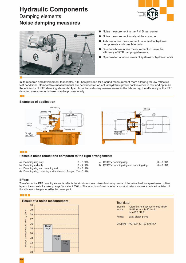
Hydraulic ComponentsDamping elementsNoise damping measures
For advanceddrive
technology
● Noise measurement in the R & D test center
● Noise measurement locally at the customer
● Airborne noise measurement on individual hydrauliccomponents and complete units
● Structure-borne noise measurement to prove the efficiency of KTR damping elements
● Optimization of noise levels of systems or hydraulic units
In its research and development test center, KTR has provided for a sound measurement room allowing for low reflectivetest conditions. Comparative measurements are performed on an actual hydraulic power pack in order to test and optimizethe efficiency of KTR damping elements. Apart from the stationary measurement in the laboratory, the efficiency of the KTRdamping measurements taken can be proven locally.
Examples of application
a) Damping ring only 3 – 6 dBAb) Damping rod only 3 – 4 dBAc) Damping ring and damping rod 6 – 8 dBAd) Damping ring, damping rod and elastic flange 7 – 10 dBA
Effect:The effect of the KTR damping elements reflects the structure-borne noise vibration by means of the vulcanized, non-prestressed rubberlayer in the acoustic frequency range from about 200 Hz. The reduction of structure-borne noise vibrations causes a reduced radiation ofthe airborne noise produced by the power pack.
Result of a noise measurement
Possible noise reductions compared to the rigid arrangement:
e) DT/DTV damping ring 3 – 6 dBAf) DT/DTV damping ring and damping ring 6 – 8 dBA
Test data:Electric rotary current asynchronous 180Mmotor: 18,5 kW, n = 1450 1/min
type B 3 / B 5
Pump: axial piston pump
Coupling: ROTEX® 42 - 92 Shore A
Electric MotorPump
Damping ring
Damping rod
Foot flange
Oil tank type BAK
Elastic flange
BellhousingDT ring
Integrated damping ring

165
80 68 4 6 78 60 6,6
100 82 5 8 95 65 9
130 110 6 10 125 95 9
80-2.11
80-2.10
80-2.9
80-2.8
80-2.7
80-2.6
80-2.5
80-2.4
80-2.3
80-2.2
80-2.1
100-2.5
100-2.4
100-2.3
100-2.2
100-2.1
130-2.4
130-2.3
130-2.2
130-2.1
Hyd
rau
lic
Co
mp
on
ents
Ste
el T
anks
Hydraulic ComponentsDamping elementsElastic flanges
For advanceddrive
technology
● For structure-borne noise separation on the pressure and suction lines to the tank
● Suitable for bulkhead pipe fitting SV6 - SV42
● Sealing surface is moulded on
● Made from oil-resistant perbunane
● Larger types on request
ERD 100 – 2.3
Size 100 Finish bore with thread M36 x 2
Elastic flange Bulkhead pipe fitting*
Size A B a b D1 D2 dL
SV 28-L SV 25-S M 36 x 2 Ø 34
SV 22-L SV 20-S M 30 x 2 Ø 28
SV 18-L – M 26 x 1,5 Ø 24,5
– SV 16-S M 24 x 1,5 Ø 22,5
SV 15-L – M 22 x 1,5 Ø 20,5
– SV 12-S M 20 x 1,5 Ø 18,5
SV 12-L SV 10-S M 18 x 1,5 Ø 16,5
SV 10-L SV 8-S M 16 x 1,5 Ø 14,5
SV 8-L SV 6-S M 14 x 1,5 Ø 12,5
SV 6-L – M 12 x 1,5 Ø 10,5
– – – Ø 10 Standard design
SV 42-L SV 38-S M 52 x 2 Ø 50
– SV 30-S M 42 x 2 Ø 40
SV 28-L SV 25-S M 36 x 2 Ø 34
SV 22-L SV 20-S M 30 x 2 Ø 28
– – – Ø 25 Standard design
SV 42-L SV 38-S M 52 x 2 Ø 50
SV 35-L – M 45 x 2 Ø 43
– SV 30-S M 42 x 2 Ø 40
– – – Ø 35 Standard design
Order form:
* Bulkhead pipe fitting and washer do not form part of our supply.
Available from stock
Type L Type S Thread Pilot bore Commentlight heavy M for M Ø d
View A
View A
WasherBulkhead pipe fitting
Thread M
or Ød
Elastic flange

166
D 84 / D 125 / D 145
D 150
100 100 100 200 200 200 250 250
650 1800 3000 2300 4100 4000 6000 10 000
D 190 D 230 D 260 D 330 D 84 D 125 D 145
1 2 3
B4B7 D1 D2 D3 D4 LD L2 L3 L4 L5 L6 z x M 2)
min. max.
D 150/.. 18 83 122 148 83 100 78 45 5 15 13 16 30 4 x M8
D 190/.. 30 121 150 190 116 130 100 45 5 15 14 18 33 4 x M10
D 230/.. 97 143 195 234 143 160 136 58 5 18 17 23 47 4 x M12
D 260/.. 97 164 210 264 164 180 156 58 4 20 18 23 46 4 x M16
D 330/.. 120 208 264 330 208 220 201 83 6 35 23 28 64 4 x M20
D 84/.../A147 224 280 360 210 224 - 83 5 35 25 25 18 4 x M20
D 84/.../C
D 125/.../A 260 320 360 484 285 315 - 125 10 33 25 25 40 M20 3)
D 145/.../A 390 400 1) 590 370 400 - 145 12 45 35 35 47 M24 3)
Fmax. · LFperm. = ––––––––––– [N]
Lx
1) Pitch circle diameter on request.2) Tightening torque of screw quality 5.6.3) Number of fixing holes on request.
Order form:
D 230 14
Damping ring Size Internal code
The permissible weight load Fperm.
must not be exceeded by the existing weight load FG (radial or axial).
With a different distance of center of gravity LX the permissible weight load is converted.
If LX < L, Fmax. = Fperm.
Distance of center of gravity for radial load
L [mm]Perm. weight load
Fmax. [N]
Permissible radial and axial weight load of damping rings based on an ambient temperature of + 60 °C
Arrangement of dampingring D up to D 330
Design V1
Bellhousing withdamping ring
Design B3/B5
● Vulcanized and failsafe (up to D 330, DBGM)
● High weight load permissible (e. g. multiple pumps)
● Excellent damping properties
● Excellent resistance to hydraulic oil
● Sealing lips are moulded on (up to size 330) – no additional sealing required
● For the bellhousing selection you require please eithersee our selection programme at www.ktr.com or order the selection stored on CD-ROM
Dimensions [mm]Dampingring
Size
Integrated seal
Cams for pumps withrectangular connectiononly for damping ring type D 150
Hydraulic ComponentsDamping elementsDamping rings D
For advanceddrive
technology

167
160 130 111 4 x M 8 16,5 35 4 x 9 4 x 14,5 18 12
200 165 145,2 4 x M 10 20 40 4 x 11 4 x 17,5 20 23
250 215 191 4 x M 12 17,5 45 4 x 13 4 x 19,5 22 40
300 265 235 4 x M 12 17,5 50 4 x 13 4 x 19 24 40
350 300 261 4 x M 16 31 60 4 x 17 4 x 25 26 100
400 350 301 4 x M 16 31 70 4 x 17 4 x 25 31 100
450 400 351 8 x M 16 31 80 8 x 17 8 x 25 41 100
550 500 451 8 x M 16 30 68 8 x 17 8 x 25 23 210
660 600 551 8 x M 20 30 68 8 x 22 8 x 33 23 410
71 DTV 160
80, 90 S / 90 L DT 200
100 L / 112 M DT 250
132 S / 132 M DT 300
160 M/160L,180M/180L DT 350
200 L DT 400
225 S / 225 M DT 450
250 M, 280 S / 280 M DT/DTV 550
315 S / 315 M DT/DTV 660
2 31
Hyd
rau
lic
Co
mp
on
ents
Ste
el T
anks
Hydraulic ComponentsDamping elementsDamping rings type DT (DBGM) and DTV
For advanceddrive
technology
● DTV for vertical assembly only!● To reduce noise between drive unit and tank by means
of rubber flexible separation
● Type DT for horizontal and vertical assembly
● Type DT is protected against separation (failsafe) by means of a special design (registered design of theinterconnected parts)
● Pressure-loaded elastomer due to the interconnectedparts
● High permissible radial, angular and axial load
● Sealing lips are moulded on - no additional sealings required
IEC -motor
Size
Damping ring
Size
Screwtightening torque
[Nm]
Dimensions [mm]
D D1 D2 z x G L L1 z x d z x d1 l
Permissible radial weight and bending load of DT damping rings with an operating temperature of + 60 °C
DT size 200 250 300 350 400 450 550 660
Fperm. [N] 370 720 1450 3600 4800 6600 13000 24000
Mb perm. [Nm] 30 65 175 740 1100 1600 4400 9000
Fperm. � FP + FM Mb perm. � FM · l1 - FP · l2
Example of assembly:
horizontal (type DT)with fixings installed reciprocally
Arrangement of DT ring
Sealing lips on both sides
Through holes for easy assembly in vertical design
Damping ringtype DT
Electric motor
Bellhousing
Tank wall
Dampingring
Pump
Damping ring type DT Damping ring type DT.../2

168 168
16 11 M 10 4 45 145 18 83
18 83
18 14 M 12 5 45 190
30 121
45 18 83
20 14 M 12 5 45 234 30 121
58 97 143
145 148
148
187
190
225
231 148
225
231 190
225
231 234
90
100
124
106
124
145
106
124
145
155
130
144
179
195
155
130
144
183
195
168
143
157
196
208
D 150/.. PTFL 200 200 165 130
D 150/..
D 190/..
D 150/..
D 190/..
D 230/..
PTFL 250 250 215 180
PTFL 300 300 265 230
90 S/90 L 1,1
(24x50) 1,5
132 S/ 5,5
132 M
(38x80) 7,5
2,2
3
100 L/
112 M
(28x60)
PK 200/11/...
PL 200/11/...
PK 200/30/...
PK 250/15/...
PL 250/15/...
PK 250/17/...
PK 250/15/...
PL 250/15/...
PK 250/17/...
PK 300/8/...
PK 300/9/...
PL 300/9/...
PK 300/15/...
PL 300/15/...
PK 300/8/...
PK 300/9/...
PL 300/9/...
PK 300/15/...
PL 300/15/...
PK 300/8/...
PK 300/9/...
PL 300/9/...
PK 300/15/...
PL 300/15/...
Min. Max.A1 B B1 L1 ges. L3 K M h LD B3 B4 B5 B5D
Hydraulic ComponentsDamping elementsDamping rings type D in combination with bellhousings 1)
For advanceddrive
technology
● The damping ring forms a centering unit with the bellhousing
● Combination also available for multiple pumps
● For the mounting of the damping ring special bellhousings are available to build a short design
● For the bellhousing selection you require please either see our selection programme at www.ktr.com or order the selection stored on CD-ROM
● Notice our mounting instructions
For IEC-motor from size 225 S / 225 M 8 fixing holesand through holes are offset 22,5° to the verticle.
Dimensions [mm]IEC - kW Bell- Damping FootMotor with housing ring flangesize n =
(shaft end) 1500
d1 x l3 1/min Size Size Size
Please mention inyour order if ventingholes or oil bleeds,respectively, are requested.For dimensions see page 158/159.
1) Preferred combinations with short bellhousings, other combinations on request (see pages 158 and 159), phone (0 59 71) 798-0.
• For your power pack please pay attention to a separation of the piping, e. g. by tubes or elastic flanges (see page 165).• For further measures of noise damping we recommend to use damping rods (see page 170/171) or DT/DTV rings (see page 167).

169
1)
PL PK 250 15 92 D 150 23
25
26
18 83
25 45
26
30 121
25 17 M 16 6 260
26
143
25
58 97
26
164
25
45 30 121
20 17 M 16 6 300 143
58 97
164
45 30 121
25 17 M 16 6 350 143
58 97
164
83 120 208
45 30 121
143
26 17 M 16 6 58 450* 97
164
83 120 208
58 97 164
32 22 M 20 8 550*83 120 208
125 260 320
148
190
252
234
264
290
190
234260
264
325
190
260
325
234
260
325
264
260
325 330
400
190
340
400
234
340
400
264
340
400
330
340
500
340264
500
340330
500 484
175
190
204
229
175
188
204
229
188
204
217
242
188
204
217
242
247
210
215
229
228
242
228
242
247
230
249
267
243
234
262
280
243
234
262
280
268
237
252
262
248
265
275
248
265
275
275
290
300
310
318
330
343
372
PTFL 350 300 300 250
D 190/..
D 150/..
D 230/..
D 190/..
D 260/..
D 230/..
D 260/..
D 190/..
D 230/..
D 260/..
D 330/..
D 190/..
D 230/..
D 260/..
D 330/..
D 260/..
D 125/../..
D 330/..
PTFL 550 550 500 450
PTFS 660 660 600 550
PTFS 450 450 400 350
PTFS 400 400 350 300
160 M/ 11160 L 15
(42x110)
180 M/ 18,5180 L 22
(48x110)
225 S 37
225 M 45
(60x140)
250 M 55
(65x140)
280 S 75
280 M 90
(75x140)
315 S 110
315 M 132
315 L 160
(80x170) 200
200 L/ 30
(55 x 110)
PK 350/11/...
PL 350/11/...
PK 350/18/...
PL 350/18/...
PK 350/11/...
PL 350/11/...
PK 350/18/...
PL 350/18/...
PK 350/11/...
PL 350/11/...
PK 350/18/...
PL 350/18/...
PK 350/11/...
PL 350/11/...
PK 350/18/...
PL 350/18/...
PL350/48/98
PL 400/03/...
PK 400/12/...
PL 400/12/...
PK 400/12/...
PL 400/12/...
PK 400/12/...
PL 400/12/...
PL400/48/98
PL450/05/94
PK450/12/94
PL450/12/94
PL450/05/96
PK450/06/96
PK450/12/96
PL450/12/96
PL450/05/98
PK450/06/98
PK450/12/98
PL450/12/98
PL 450/05/...
PK550/04/94
PL550/04/94
PK550/08/94
PK550/04/96
PL550/04/96
PK550/08/96
PK550/04/98
PL550/04/98
PK550/08/98
PK 550/04/...
PL 550/04/...
PK 550/08/...
PK660/03/98
PL660/03/98
PK 660/03/...
PL 660/03/...
PK 660/03/...
Min. Max.A1 B B1 L1 ges. L3 K M h LD B3 B4 B5 B5D
Hyd
rau
lic
Co
mp
on
ents
Ste
el T
anks
Hydraulic ComponentsDamping elementsDamping rings type D in combination with bellhousings 1)
For advanceddrive
technology
Preferred combinations with short bellhousings, other combinations on request (see pages 158 and 159), phone (0 59 71) 798-0.
Flange Model Internal Damp- Size Internaldiameter of code code ing codeIEC-Motor ring
New bellhousingdesign, short, “K”
New bellhousingdesign, Long
Order form:
Details of the order designation are shown in our computer selection programme, or please mention the IEC-motor size and the detailed pump type for a selection.
Dimensions [mm]
* Passing from dimension B3 to the flange with radius R = 5
IEC - kW Bellhousing Damping FootMotor with ring flangesize n =
(shaft end) 1500
d1 x l3 1/min Size Size Size
170
DSM 71
DSM 80
DSM 90 S
DSM 90 L
DSM 100 L
DSM 112 M
DSM 132 S
DSM 132 M
DSM 160 M
DSM 160 L
DSM 180 M
DSM 180 L
DSM 200 L
DSM 225 S
DSM 225 M
DSM 250 M
DSM 280 S
DSM 280 M
DSM 315 S
DSM 315 M
DSM 315 L
71
80
90 S
90 L
100 L
112 M
132 S
132 M
160 M
160 L
180 M
180 L
200 L
225 S
225 M
250 M
280 S
280 M
315 S
315 M
315 L
196
176
196
240
240
240
280
280
340
416
416
446
492
492
492
492
614
614
614
614
704
L L1 L2 h h1 h2 b b1 b2 d D M
156
146
156
205
205
205
245
245
300
370
370
400
430
430
445
445
570
570
570
570
660
90
100
100
125
140
140
140
178
210
254
241
279
305
286
311
349
368
419
406
457
508
40
40
40
40
40
40
45
45
60
60
60
60
60
60
60
60
60
60
60
60
60
8
8
8
8
8
8
8
8
15
15
15
15
15
15
15
15
15
15
15
15
15
12
12
12
12
12
12
12
12
15
15
15
15
15
15
15
15
15
15
15
15
15
50
50
50
50
50
50
50
50
70
70
70
70
70
70
70
100
100
100
120
120
120
21
22
24,5
24
24
20
20
20
28
28
35
35
35
35
35
50
50
50
60
60
60
25
25
25
25
25
25
25
25
35
35
35
35
35
35
35
50
50
50
60
60
60
14
14
14
14
14
14
14
14
18
18
18
18
22
22
22
22
22
22
22
22
22
20
20
20
20
20
20
20
20
26
26
26
26
33
33
33
33
33
33
33
33
33
M 6
M 8
M 8
M 8
M10
M10
M10
M10
M12
M12
M12
M12
M16
M16
M16
M20
M20
M20
M24
M24
M24
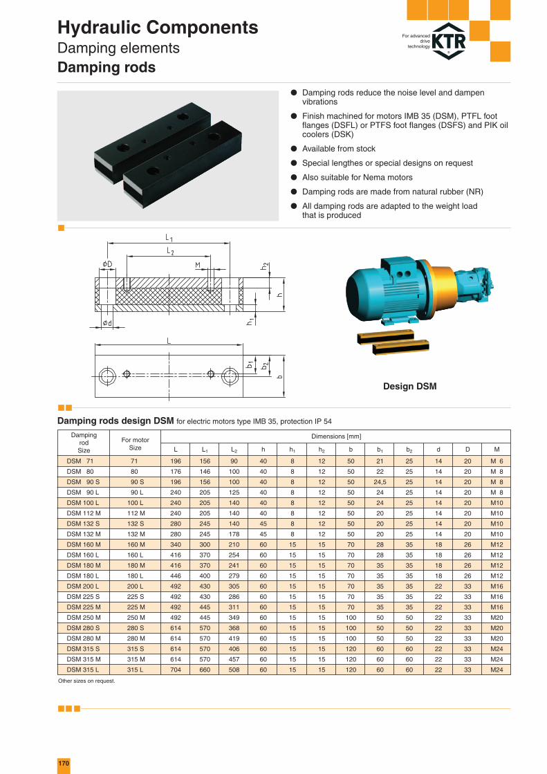
Design DSM
Hydraulic ComponentsDamping elementsDamping rods
For advanceddrive
technology
● Damping rods reduce the noise level and dampen vibrations
● Finish machined for motors IMB 35 (DSM), PTFL footflanges (DSFL) or PTFS foot flanges (DSFS) and PIK oilcoolers (DSK)
● Available from stock
● Special lengthes or special designs on request
● Also suitable for Nema motors
● Damping rods are made from natural rubber (NR)
● All damping rods are adapted to the weight load that is produced
Other sizes on request.
For motorSize
DampingrodSize
Dimensions [mm]
Damping rods design DSM for electric motors type IMB 35, protection IP 54

171
PTFL 160
PTFL 200
PTFL 250
PTFL 300
PTFL 350
DSFL 160
DSFL 200
DSFL 250
DSFL 300
DSFL 350
176
176
230
270
305
L L1 L2 h h1 h2 b b1 b2 d D M
130
130
140
170
200
50
60
60
80
110
40
40
40
40
60
8
8
8
8
15
12
12
12
12
15
50
50
50
50
70
10
15
15
15
25
25
25
25
25
35
14
14
14
14
18
20
20
20
20
26
M 8
M10
M12
M12
M16
PTFS 250
PTFS 300
PTFS 350
PTFS 400
PTFS 450
PTFS 550
PTFS 660
DSFS 250
DSFS 300
DSFS 350
DSFS 400
DSFS 450
DSFS 550
DSFS 660
240
280
325
350
385
490
635
L L1 L2 h h1 h2 b b1 b2 d D M
140
180
200
234
270
350
415
185
225
265
300
335
415
495
40
40
60
60
60
60
60
8
8
15
15
15
15
15
12
12
15
15
15
15
15
50
50
70
70
70
100
100
17,5
17,5
25
25
25
25
30
25
25
35
35
35
50
50
13
13
17
17
17
18
22
20
20
26
26
26
26
33
M12
M12
M16
M16
M16
M16
M20
PIK 200
PIK 250
PIK 300
PIK 350
DSK 200
DSK 250
DSK 300
DSK 350
240
270
280
325
L L1 L2 h h1 h2 b b1 b2 d D M
210
240
250
295
154,5
175,5
199,5
243,5
40
40
45
60
8
8
8
15
12
12
12
15
50
50
50
70
25
25
25
35
25
25
25
35
14
14
14
14
20
20
20
20
M12
M12
M12
M12
Hyd
rau
lic
Co
mp
on
ents
Ste
el T
anks
Hydraulic ComponentsDamping elementsDamping rods
For advanceddrive
technology
● Damping rods reduce the noise level and dampen vibrations
● Finish machined for motors IMB 35 (DSM), PTFL footflanges (DSFL) or PTFS foot flanges (DSFS) and PIK oilcoolers (DSK)
● Available from stock
● Special lengthes or special designs on request
● Also suitable for Nema motors
● Damping rods are made from natural rubber (NR)
● All damping rods are adapted to the weight load that is produced
Forfoot flange
DampingrodSize
Dimensions [mm]
Damping rods design DSFL for foot flange PTFL
Forfoot flange
DampingrodSize
Dimensions [mm]
Damping rods design DSFS for foot flange PTFS
For coolerSize
DampingrodSize
Dimensions [mm]
Damping rods design DSK for PIK bellhousings with integrated oil cooler with feet
Design DSFL Design DSFS Design DSK
172
L1 L2 L3 A A1 A2 A3 A4 B B1 B2 B3 D M h
100 154,5 94,5 275 225 163 112,5 180 165 130 130 145 20 167 M10 116,5
110 154,5 94,5 275 225 163 112,5 180 165 130 130 145 20 167 M10 116,5
124 154,5 94,5 275 225 163 112,5 180 165 130 130 145 20 167 M10 116,5
124 175,5 115,5 308 250 180 125 220 215 180 150 190 20 192 M12 129
135 175,5 115,5 305 250 180 125 220 215 180 150 190 20 192 M12 129
144 199,5 139,5 359 300 205 154 260 265 230 175 234 30 242 M12 154
155 199,5 139,5 359 300 205 154 260 265 230 175 234 30 242 M12 154
168 199,5 139,5 359 300 205 154 260 265 230 175 234 30 242 M12 154
188 243,5 183,5 405 360 230 175 310 300 250 200 260 50 292 M16 184
204 243,5 183,5 405 360 230 175 310 300 250 200 260 50 292 M16 184
100 L/ 2,2112 M 3(28x60) 4
90 S/90 L 1,1(24x50) 1,5
80 0,55(19x40) 0,75
132 S/ 5,5132 M 7,5(38x80)
1115
18,522
160 M/160 L(42x110)180 M/180 LØ 48x110
B4min.
PIK 200/1/...
PIK 200/2/...
PIK 200/4/...
PIK 250/2/...**
PIK 250/4/...**
PIK 300/1/...
PIK 300/3/...
PIK 300/4/...
PIK 350/1/...
PIK 350/2/...
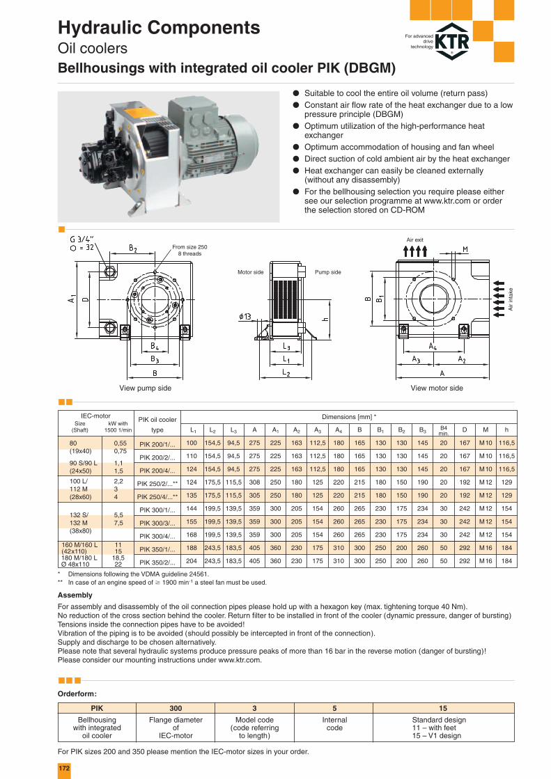
Hydraulic ComponentsOil coolersBellhousings with integrated oil cooler PIK (DBGM)
For advanceddrive
technology
* Dimensions following the VDMA guideline 24561.** In case of an engine speed of � 1900 min-1 a steel fan must be used.
● Suitable to cool the entire oil volume (return pass)● Constant air flow rate of the heat exchanger due to a low
pressure principle (DBGM)● Optimum utilization of the high-performance heat
exchanger● Optimum accommodation of housing and fan wheel● Direct suction of cold ambient air by the heat exchanger● Heat exchanger can easily be cleaned externally
(without any disassembly)● For the bellhousing selection you require please either
see our selection programme at www.ktr.com or orderthe selection stored on CD-ROM
Dimensions [mm] *IEC-motorSize kW with
(Shaft) 1500 1/min
PIK oil cooler
type
Orderform:
PIK 300 3 5 15
Bellhousing Flange diameter Model code Internal Standard designwith integrated of (code referring code 11 – with feet
oil cooler IEC-motor to length) 15 – V1 design
For PIK sizes 200 and 350 please mention the IEC-motor sizes in your order.
Assembly
For assembly and disassembly of the oil connection pipes please hold up with a hexagon key (max. tightening torque 40 Nm).No reduction of the cross section behind the cooler. Return filter to be installed in front of the cooler (dynamic pressure, danger of bursting)Tensions inside the connection pipes have to be avoided!Vibration of the piping is to be avoided (should possibly be intercepted in front of the connection).Supply and discharge to be chosen alternatively.Please note that several hydraulic systems produce pressure peaks of more than 16 bar in the reverse motion (danger of bursting)!Please consider our mounting instructions under www.ktr.com.
From size 2508 threads
Air exit
Air
inta
ke
View pump side View motor side
Pump sideMotor side

173
PIK 200
PIK 250
PIK 300
PIK 350
PIK 200
PIK 250
PIK 300
PIK 350
�T = 50 K
�T = 40 K
�T = 30 K
�T = 20 K
�T = 50 K
�T = 40 K
�T = 30 K
�T = 20 K
�T = 50 K
�T = 40 K
�T = 30 K
�T = 20 K
�T = 50 K
�T = 40 K
�T = 30 K
�T = 20 K
� = 100 mm2/s
� = 80 mm2/s� = 60 mm2/s� = 40 mm2/s
� = 100 mm2/s
� = 80 mm2/s� = 60 mm2/s� = 40 mm2/s
� = 100 mm2/s
� = 80 mm2/s� = 60 mm2/s� = 40 mm2/s
� = 100 mm2/s
� = 80 mm2/s� = 60 mm2/s� = 40 mm2/s
2,0
1,8
1,6
1,4
1,2
1,0
0,8
0,6
0,4
0,2
0,0
3,0
2,5
2,0
1,5
1,0
0,5
0,0
1,4
1,2
1,0
0,8
0,6
0,4
0,2
0,0
1,4
1,2
1,0
0,8
0,6
0,4
0,2
0,0
0 5 10 15 20 25 30 35 40 45 50 55 60 65 70 75 80
0 5 10 15 20 25 30 35 40 45 50 55 60 0 5 10 15 20 25 30 35 40 45 50 55 60
0 5 10 15 20 25 30 35 40 45 50 55 60 65 70 75 80
0 2 4 6 8 10 11 12 14 16 18 20 22 24 26 28 30 32 34 36 38 40
3,0
2,5
2,0
1,5
1,0
0,5
0,0
3,5
3,0
2,5
2,0
1,5
1,0
0,5
0,0
2,5
2,0
1,5
1,0
0,5
0,0
6
5
4
3
2
1
0
1,00,90,80,70,60,50,40,30,20,10,0
0 2 4 6 8 10 11 12 14 16 18 20 22 24 26 28 30 32 34 36 38 40
0 2 4 6 8 10 11 12 14 16 18 20 22 24 26 28 30 32 34 36 38 400 2 4 6 8 10 12 14 16 18 20 22 24 26 28 30 32 34 36 38 40
Electric motor
Damping rods design DSK
KTR productsavailable from stock
PIKfan wheel
ROTEX®-motor hub
PIK oil cooler
PIK feet
ROTEX®-pump hub
ROTEX®-spider
Hydraulicpump
Systemarrangement
2. Working pressureThe maximum permissible working pressure for the oil cooler is 16 bar. Max. operating pressure in case of static load 40 bar.(All values apply for the medium pressure cooler.)
The diagrammes shown are based on actual measurements of the PIK oil cooler performed in the KTR R & D test center.With 3000 1/min the cooling effect is increased by 50%.
4. Fan wheelTorsional direction looking onto the pump – right –standard design.
Performance of the fan with 1500 1/min
PIK 200 = 25 WPIK 250 = 40 WPIK 300 = 125 WPIK 350 = 230 W
Air pressure rate in m3/h at 1500 1/min
PIK 200 = abt. 90 m3/hPIK 250 = abt. 200 m3/hPIK 300 = abt. 400 m3/hPIK 350 = abt. 860 m3/h
5. Cooler connectionR 3/4“ internal thread
6. Oil flowFor a higher oil flow than indicated in the above diagramme, please consult with our Engineering Department, phone (0 59 71) 798-0.
Cooling effect PK (kW)
Hydraulic ComponentsOil coolersBellhousings with integrated oil cooler PIK (DBGM)
For advanceddrive
technology
1. Cooling effect for a speed of 1500 1/min depend-ing on the temperature difference between oil intake and air intake and oil volume
3. Pressure difference depending on oil flow andoil viscosity
Viscosity measured up to 100 mm2/s.Higher viscosity on request.
Volume flow Q (L/min)
Cooling effect PK (kW)
Volume flow Q (L/min)
Volume flow Q (L/min)
Cooling effect PK (kW)
Volume flow Q (L/min)
Cooling effect PK (kW)
Pressure difference p (bar)
Volume flow Q (L/min)
Pressure difference p (bar)
Volume flow Q (L/min)
Volume flow Q (L/min)
Pressure difference p (bar)
Volume flow Q (L/min)
Pressure difference p (bar)
Hyd
rau
lic
Co
mp
on
ents
Ste
el T
anks

TAK 1014 M O2W– FW– 1– 1–– –
174
4575
225
330
5..
7..
10..
90
210
22
46
106
-
23
53
17
34
82
-
16
40
26
52
122
-
24
58
TAK
TEK
TAK TEK
2) Operating temperatureThe max. operating temperatures are:TAK = 120 °C; TEK = 95 °C
3) Operating pressureThe max. operating pressure of TAK and TEK is:Shell = 35 bar; Tubes = 16 bar
Componentsmounting bracket
shellbaffle
end plates
cooling finstype designation plate
tubes
end caps
gaskets
additional installation
Standard coolers
steel
TAK = steel; TEK = brass
aluminium
TAK = copper/nickel; TEK = copper
grey cast iron
nitrile rubbercellulose fibres
Seawater coolers
steel
copper nickel alloy
aluminium
TAK = copper/nickel; TEK = copper
grey cast iron(with copper/nickel layer)
nitrile rubbercellulose fibres
zinc anode
Technical data
Orderform:
ATTENTION: Incorrect assembly can lead to a damage to the cooler!
1) Maximum flows
All flows l/min.
SeriesTAK/TEK
OilShell
1-pass 2-pass 4-pass
TAK = built-on cooler/TEK = built-in cooler
Unit size
Oil connection typeM = BSPF FM = SAE-flange (optional)
Cooling water connection system1W = 1-pass 2W = 2-pass 4W = 4-pass
Bypass valveO = without B = with
FW = fresh water SW = seawater
Tubes1 = copper - standard with TEK 2 = copper/nickel - standard with TAK
Tube sheet1 = steel - standard with TAK 2 = brass - standard with TEK 3 = saltwater-proof
For advanceddrive
technology
Hydraulic ComponentsOil coolersOil-water coolers
To define the cooling performance or the cooler please contact KTR (phone: +49-59 71/7 98-4 24).
● Öil-water coolers as tube-bank heat exchanger● Designs: TAK (built-on cooler)
TEK (built-in cooler)● Wide fields of applications in industry● Large cooling surface with low dimension● High effectivity - heat exchange performance up to
230 kW due to aluminium laminas pushed over bank oftubes (cooling surface = 0,43 m² up to 18,41 m²)
● Minimum flow resistance due to large oil connections● Maximum pressure: oil = 35 bar; water = 16 bar● Optionally available in saltwater-proof design● Easy to clean due to removable end caps
Materials
Water Water (tubes Cu) Water (tubes CN)
2-pass 4-pass 2-pass 4-pass

175
A
B
C
D
DC
B A
D
C
D
C
B A
A
B
C
D
A
TAK - 10..TAK - 7..TAK - 5..
1289065
B
201512
E
11610382*
G
11610383
I
16512789
L
10276
63,5M
Ø11x25Ø11x19Ø9x16
Q
G 1/4”G 1/4”
-R
G 1 1/2”G 1 1/4”G 3/4”
T
1026641
A
TAK - 10..TAK - 7..TAK - 5..
1289065
B
201512
E
1139183
G
1109585
I
16512789
L
10276
63,5M
Ø11x25Ø11x19Ø9x16
Q
G 1/4”--
R
G 1 1/4”G 1”
G 3/8”T
1026641
U
6041
TAK - 10..TAK - 7..
12890
2015
112107
11095
165127
10175
Ø11x25Ø11x19
G 1/4”G 1/4”
G 3/4”G 1/2”
10266
6444
28
1872633143654165176709752833854355376899943894405416949991303
1872653143654165176729762583604115136659953694205226749791284
--------
2623644155166699743634135156679721277
5597148199250351504809761772283304827871572073094617661071
5357575757575757737373737373929292929292
18926531636741851967297627237342452667898339244354469710021306
0,430,730,941,131,431,742,353,571,382,182,533,294,446,734,385,176,739,0613,7418,41
3,153,603,454,054,55,16,07,87,38,48,8
10,211,615,515,416,919,821,830,539,8
G 3/4”G 3/4”G 3/4”G 3/4”G 3/4”G 3/4”G 3/4”G 3/4”
G 1 1/2”G 1 1/2”G 1 1/2”G 1 1/2”G 1 1/2”G 1 1/2”G 1 1/2”G 1 1/2”G 1 1/2”G 1 1/2”G 1 1/2”G 1 1/2”
--------
SAE 1 1/2”SAE 1 1/2”SAE 1 1/2”SAE 1 1/2”SAE 1 1/2”SAE 1 1/2”
SAE 2”SAE 2”SAE 2”SAE 2”SAE 2”SAE 2”
--------
35,835,835,835,835,835,842,942,942,942,942,942,9
--------
69,969,969,969,969,969,977,777,777,777,777,777,7
TAK-505TAK-508TAK-510TAK-512TAK-514TAK-518TAK-524TAK-536TAK-708TAK-712TAK-714TAK-718TAK-724TAK-736TAK-1012TAK-1014TAK-1018TAK-1024TAK-1036TAK-1048
CD F H
WT1)
[m2] X V
Type „2-pass“ Type „4-pass“
1-pass 2-pass 4-pass
Weight[kg]
Oil connectionStandard
SOptional
SAE-flangeType
1) WT = Heat exchange surface [m2]Flange TAK 700 = 1 1/2”; flange TAK 1000 = 2”
TAK - Type “2-pass”
TAK - Type “4-pass”
* outside TAK - 505 = 66 mm
Dimensions [mm]
For advanceddrive
technology
Hydraulic ComponentsOil coolersOil-water coolers - Design TAK
Hyd
rau
lic
Co
mp
on
ents
Ste
el T
anks
- medium to be cooled
- cooled medium
- cooling water „on“
- cooling water „off“
TAK - Type „1-pass“
- medium to be cooled
- cooled medium
- cooling water „on“
- cooling water „off“
TAK - Type „2-pass“
Type
Unit dimensions
Dimensions [mm]Type

176
TEK-M-508
TEK-M-512
TEK-M-514
TEK-M-518
TEK-M-524
TEK-M-536
TEK-M-708
TEK-M-712
TEK-M-714
TEK-M-718
TEK-M-724
TEK-M-736
TEK-M-1012
TEK-M-1014
TEK-M-1018
TEK-M-1024
TEK-M-1036
TEK-M-1048
285
386
437
539
691
996
296
397
448
550
702
1007
425
476
578
730
1035
1340
140
241
292
394
546
851
141
242
293
395
547
852
220
271
373
525
830
1135
145
145
145
145
145
145
155
155
155
155
155
155
205
205
205
205
205
205
78
78
78
78
78
78
95
95
95
95
95
95
120
120
120
120
120
120
50
50
50
50
50
50
65
65
65
65
65
65
84
84
84
84
84
84
150
150
150
150
150
150
185
185
185
185
185
185
230
230
230
230
230
230
65
65
65
65
65
65
89
89
89
89
89
89
128
128
128
128
128
128
130
130
130
130
130
130
165
165
165
165
165
165
205
205
205
205
205
205
30
30
30
30
30
30
47
47
47
47
47
47
62
62
62
62
62
62
R 1/2”
R 1/2”
R 1/2”
R 1/2”
R 1/2”
R 1/2”
R 1”
R 1”
R 1”
R 1”
R 1”
R 1”
R 1 1/4”
R 1 1/4”
R 1 1/4”
R 1 1/4”
R 1 1/4”
R 1 1/4”
-
-
-
-
-
-
18
18
18
18
18
18
22
22
22
22
22
22
-
-
-
-
-
-
R 1/2”
R 1/2”
R 1/2”
R 1/2”
R 1/2”
R 1/2”
R 3/4”
R 3/4”
R 3/4”
R 3/4”
R 3/4”
R 3/4”
-
-
-
-
-
-
48
48
48
48
48
48
63
63
63
63
63
63
0,73
1,13
1,43
1,74
2,35
3,57
1,38
2,18
2,53
3,29
4,44
6,73
4,38
5,17
6,73
9,06
13,74
18,41
G 1”
G 1”
G 1”
G 1”
G 1”
G 1”
SAE 1 1/2”
SAE 1 1/2”
SAE 1 1/2”
SAE 1 1/2”
SAE 1 1/2”
SAE 1 1/2”
SAE 2”
SAE 2”
SAE 2”
SAE 2”
SAE 2”
SAE 2”
A B C D E G O H I K L M NF *
WT1)
[m2]
U V W X Y Z
SAE 1”
SAE 1 1/2”
SAE 2”
70
93
102
52,37
69,85
77,77
55
78
90
26,19
35,71
42,88
25
38
49
M10
M12
M12
Hydraulic ComponentsOil coolersOil-water coolers - Design TEK
For advanceddrive
technology
1) WT = Heat exchange surface [m2]
* Unit size 500: SAE 1“ optional. Unit sizes 700+1000: thread optional
TEK
Unit dimensions
TypeGeneral dimensions [mm] 2-pass 4-pass
SAE-connection3000 P.S.I.
„2-pass“ „4-pass“
WaterInlet - Outlet
OilInlet “F”

177
400 200 230600 300 230800 400 230
1000 500 2301200 600 2301400 700 2301600 800 2301800 900 2302000 1000 2302200 1100 2302400 1200 2302800 1400 2303200 1600 2303600 1800 3 x 4004000 2000 3 x 400
500 200 230750 300 230
1000 400 2301250 500 2301450 600 2301700 700 2301950 800 2302200 900 2302450 1000 2302700 1100 2302950 1200 2303450 1400 3 x 4003900 1600 3 x 4004400 1800 3 x 4004900 2000 3 x 400
450 300 230600 400 230750 500 230900 600 230
1050 700 2301200 800 2301350 900 2301500 1000 2301650 1100 2301800 1200 2301950 1300 2302100 1400 2302250 1500 2302400 1600 230
EHP 1950- 1300- G 2”- TI- 1 x 230 V-
NEWNEW
Hydraulic ComponentsTank heatersInserted heating cartridges type EHP
For advanceddrive
technology
Hyd
rau
lic
Co
mp
on
ents
Ste
el T
anks
Type TA
Type TI unheated
Without temperature control Without temperature control With temperature control
Heatingcapacity
[Watt]
Immersiondepth
T[mm]
Voltage
[V]
Heatingcapacity
[Watt]
Immersiondepth
T[mm]
Voltage
[V]
Heatingcapacity
[Watt]
Typ
e E
HP
(TA
/TI)
G 2
”w
ith
tem
per
atu
re c
on
tro
l
Typ
e E
HP
G 2
”
Typ
e E
HP
G 1
1/2
”
Immersiondepth
T[mm]
Voltage
[V]
Type EHP – G 1 1/2” Type EHP – G 2” Type EHP (TA/TI) – G 2”
As an alternative: Control of tank heater possible in combination with KTR industrial controls with more than one temperature switch point(see page 179 to 181). In this case the temperature control on the tank heater can be done without.
Order form:
Type
Capacity [W]
Immersion depth T [mm]
Size of screwing thread
TA = temperature control with external settingTI = temperature control with internal settingO = without temperature control
Please make sure to mention the voltage [V] in your order,e. g. 1 x 230 V; 2 x 400 V; 3 x 400 V
● Inserted heating cartridges to preheat hydraulic oil● Temperature control by internal or external setting
single-pole control 0 - 85 °C, 16 Ampere● Replaceable ceramic heating cartridges
(assembly without oil drain)● Steel cap from bright zinc coating● Suitable for horizontal assembly below oil level● Material: steel (other material on request)● Surface load 1.5 W/cm² for hydraulic oils● Protection class IP 65
(excluding design EHP (TA) IP 54)● Further designs available on request● The connector pin assignment is enclosed to the unit● Notice our mounting instructions (www.ktr.com)

178
EH 990- 450- G 1 1/2”- TI- 1 x 230 V-
380 200 230500 250 230750 350 230990 450 2301460 650 2301825 800 2302300 1000 230
250 240 230500 285 230
1000 380 230
TEHM 1000- 00-
NEWNEW
Technical Data:Shifting accuracy: ± 3° Surface load: 1,2 W/cm² (0,6 W/cm² on request)Voltage: 230 V (other on request) Connection cable: Three-pole, 2,5 m long including screwed cable gland M20x1,5
Hydraulic ComponentsTank heatersInserted tubular heatings type EH
For advanceddrive
technology
Without temperature control With temperature control
Cover
Max. oil level
Magneticclamp
Type TA
Type TI
Description of product:The coiled tubular heating elements to preheat hydraulic fluids in order to avoid breakdowns which may arise on machine tools,presses, hydraulic lifts etc. due to cooling of the hydraulic plants. Control with installed thermostat and cut-off temperature preset by the company to 20 °C, switching precision ~ 3 °C.
As an alternative: Control of tank heater possible in combination with KTR industrial controls with more than one temperatureswitch point (see page 179 to 181). In this case the temperature control on the tank heater can be done without.
Type EH – G 1 1/2” Type EH (TA/TI) – G 1 1/2”
Heatingcapacity[Watt]
Immersiondepth T
[mm]
Voltage
[V]
Typ
e E
HG
1 1
/2”
wit
ho
ut
or
wit
hte
mp
erat
ure
co
ntr
ol
● Inserted tubular heating element to preheat hydraulic oil● Suitable for horizontal assembly below oil level● With or without temperature control for internal or external
setting with single-pole control 0 - 85 °C, 16 Ampere● Surface load 1.5 W/cm² for hydraulic oil● Steel cap from bright zinc coating● Material: steel (other material on request)● Protection class IP 65 (excluding design EH (TA) IP 54)● Further designs available on request● The connector pin assignment is enclosed to the unit● Notice our mounting instructions (www.ktr.com)
● To preheat hydraulic oil● Inserted tank heater either horizontally to the tank ground or
vertically to the tank wall by means of magnetic clamps● Ideal solution to retrofit existing machines and plants● Assembly without oil drain● Internal control with preset cut-in or cut-off temperature (20 °C)● Shifting temperatures may be amended by KTR on customer’s
request● Other media/operating fluids available on request● The connector pin assignment is enclosed to the unit● Notice our mounting instructions (www.ktr.com)
Order form:
Inserted tank heater with magnetic clamp:Type TEHM
Type
Capacity [W]
Immersion depth T [mm]
Size of screwing thread
TA = temperature control with external settingTI = temperature control with internal settingO = without temperature control
Please make sure to mention the voltage [V] in your order,e. g. 1 x 230 V; 2 x 400 V; 3 x 400 V
Heatingcapacity
[Watt]
Overalllength L
[mm]
Voltage
[V]
Typ
e T
EH
M
Order form:Type
Capacity [W]
Cut-off temperature set bythe company to 20 °C = 00 (standard).Without temperature control = 01.Requested cut-off temperature e. g. 35 °C = 35.
179
➔
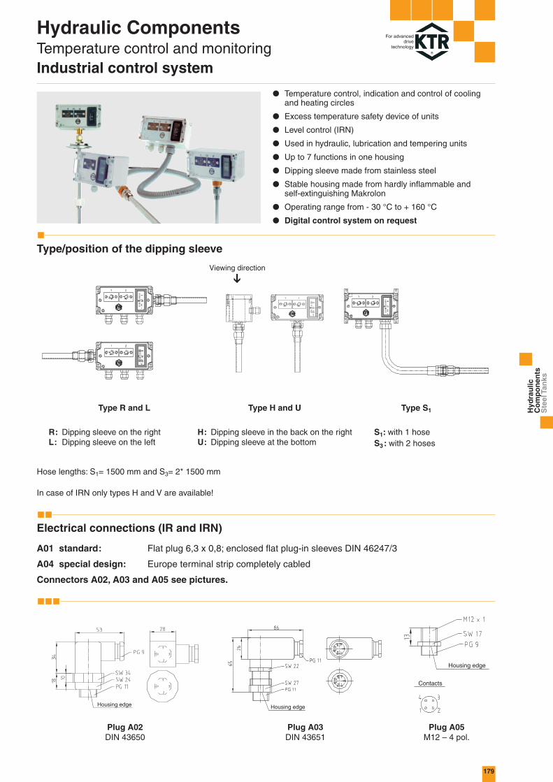
Hydraulic ComponentsTemperature control and monitoringIndustrial control system
For advanceddrive
technology
Type S1Type H and UType R and L
R: Dipping sleeve on the rightL: Dipping sleeve on the left
H: Dipping sleeve in the back on the rightU: Dipping sleeve at the bottom
S1: with 1 hoseS3: with 2 hoses
Hose lengths: S1= 1500 mm and S3= 2* 1500 mm
In case of IRN only types H and V are available!
Viewing direction
● Temperature control, indication and control of coolingand heating circles
● Excess temperature safety device of units
● Level control (IRN)
● Used in hydraulic, lubrication and tempering units
● Up to 7 functions in one housing
● Dipping sleeve made from stainless steel
● Stable housing made from hardly inflammable and self-extinguishing Makrolon
● Operating range from - 30 °C to + 160 °C
● Digital control system on request
Type/position of the dipping sleeve
Hyd
rau
lic
Co
mp
on
ents
Ste
el T
anks
Housing edge Housing edge
Housing edge
Contacts
Plug A02DIN 43650
Plug A03DIN 43651
Plug A05M12 – 4 pol.
Electrical connections (IR and IRN)
A01 standard: Flat plug 6,3 x 0,8; enclosed flat plug-in sleeves DIN 46247/3
A04 special design: Europe terminal strip completely cabled
Connectors A02, A03 and A05 see pictures.

180
A CHdED
BD1
82
120
160
240
80
80
80
120
40
30
44
44
85
85
85
100
25
45
35
40
5,2
5,2
5,2
5,2
94
94
94
134
70
108
148
228
1
2
3
4 / 5 / 6 / 7
RangeDegrees Celcius
Max. probe temperaturelimiting temperature
Shifting differenceKelvin
Controllers and temperature indication (IR and IRN)
* Manual adjustment
Type Function
00 Adjustable controller - 30 to 40 80 ~5
02 Adjustable controller 0 to 80 120 ~5
03 Adjustable controller 10 to 120 160 ~5
04 Adjustable controller 10 bis 120 160 ~10
05 Adjustable controller 60 to 160 200 ~5
07 Adjustable limiter* 0 to 150 200 ~5
T1 Thermometer 0 to 120 140
T2 Thermometer - 40 to 80 100
inst
alla
tion
leng
th
appr
ox.1
00 m
mea
ch c
ontro
ller
Hydraulic ComponentsTemperature control and monitoringIndustrial control system
For advanceddrive
technology
Type: IR
Dimensions of the housing (IR and IRN) Dimensions of the swimmer (IRN)
Type: IRN (with level switch)
Dimensions of the dipping sleeve IR
Length of the dipping sleeve IRN: EL = L1 + 100 mm/controllere. g. EL = installation length/ length of the dipping sleeve
Lowest switch point L1 = 250 mm, IRN with 2 controllersEL = 250 mm + 2 x 100 mmEL = 450 mm
FormSwimmerType S1 – S3 Dimensions
MaterialNumber offunctions
Cylinder
Cylinder
Cylinder
Ball
Hostaform C
Hostaform C
1.4571
1.4571
Standard
SW01
SW02
SW03
Type/ EL - mm installation length 100 200 300 400 500 900
ET - mm minimum depth of immersion referring to the number of installed functions1 – 3 functions 904 – 6 functions 1807 functions 270

181
IR 200 H 03A01 – 02– 02– T1–– –
PE
LED12 - 24 V
16 A (2,5)/250 VAC
10 A (1,5)/400 VAC
2
3
4
0,5 K/min.
IRN 400 U2 03 70A01 SW1200– –02– –– T1 –– –
LED240 V
5
6
Hydraulic ComponentsTemperature control and monitoringIndustrial control system
For advanceddrive
technology
Level contact(s)Connection terminal 2,5 mm2 for wire end ferruleslower (first) contact higher (second) contact
Technical data Technical data
Index
green
red
red + green
Index
green
red
Max. shifting power (W/VA) 60
Max. shifting voltage (V AC) 250
Max. shifting current (A) 1T max.dependenton the type
Type
Length of the dipping sleeve
Position of dipping sleeve
Connection
Requested controller or thermometer (max. 7).Arrangement according to requested assembly.If LED is requested, the figure 0 in the controller name is replaced by the respective index number (e. g. controller 02 and LED red = 32).
Controller 1 ... XConnection 6,3 AMP
Insulated plug
Pin connection each controller or level contactPE - connection (customer)
Orderform „IR“:
Hyd
rau
lic
Co
mp
on
ents
Ste
el T
anks
Orderform „IRN“ (with level switch):
Type
Length of the dipping sleeve
Pos. of dipping sleeve and number of switch points (max. 3)
Connection
Requested controller or thermometer (max. 6).Arrangement according to requested assembly.If LED is requested, the figure 0 in the controller name is replaced by the respective index number (e. g. controller 02 and LED red = 32).
Position of switch point L1
Position of switch point L2 (Indicate only if requested)
Float type (indicate only in case of special design)
Technical dataAccuracy of indication
Housing materialDipping sleeveCable screwingProbe + capillary tubeShifting power
Failsafety
Class 3 according to DIN 16203Polycarbonate (makrolon)1.4301PolyamideCu16 A (2,5)/250 VAC10 A (1,5)/400 VAC0,5 A/24 VDCfurther dataon request2000 VAC between unifiedcontacts and mass1150 VAC between open contacts
Contact selectionContact materialSetting gangeShifting accuracyAmbient temperatureTest Certificates
IsulationProtection classCable screwingMax. operating pressureof the dipping sleeveIndication of thermometer
Unipolar changerHard silver Ag~ 30 °C to 160 °C~ 4 °C~ 35 °C to 80 °CVDE 0631, NF, SEMKO,Demko, ÖVE, KEMAAccording to VDEIP 65M16 with strain relief16 bar
~ 30 °C to 160 °C
Index

182
BAK 13
BAK 44
BAK 30
BAK 70
11,5
40,0
27,0
63,0
For advanceddrive
technology
● Made from aluminium for depressurized operation(0,5 bar at maximum)
● With oil collecting groove moulded on periphery for collection of leakage oil (Water Resources Act)
● O-ring seal for all tank sizes, ready to use● No painting or priming of the tank required● Good heat loss capacity due to high caloric conductibility
and large heat dissipating surfaces● All tanks are 100 % tight and may be stacked without
jamming● All sizes available from stock● All tanks including drain plug similar to DIN 908● Temperature resistant up to + 100 °C
Hydraulic ComponentsAluminium tanksDesign BAK
Avail. volume [Litres] Seal
O-ring seal RS 13 NBR
Avail. volume [Litres] Seal
O-ring seal RS 44 NBR
Avail. volume [Litres] Seal
O-ring seal RS 30 NBR
Avail. volume [Litres] Seal
O-ring seal RS 70 NBR
Tanks with oil collecting groove BAK 13, BAK 30, BAK 44 and BAK 70

183
BAK 10
BAK 40
BAK 20
BAK 63
9,5
40,0
18,0
63,0
NEWNEW
Avail. volume [Litres] Seal
Flat seal FD 10
Avail. volume [Litres] Seal
O-ring seal RS 44 NBR
Avail. volume [Litres] Seal
Flat seal FD 20
Avail. volume [Litres] Seal
O-ring seal RS 70 NBR
Tanks without oil collecting groove BAK 10, BAK 20, BAK 40 and BAK 63
For advanceddrive
technology
Hyd
rau
lic
Co
mp
on
ents
Ste
el T
anks
● Made from aluminium for depressurized operation(0,5 bar at maximum)
● Without oil connecting groove● O-ring seal or flat seal for all tank sizes, ready to use● No painting or priming of the tank required● Good heat loss capacity due to high caloric conductibility
and large heat dissipating surfaces● All tanks are 100 % tight and may be stacked without
jamming● All sizes available from stock● All tanks including drain plug similar to DIN 908● Temperature resistant up to + 100 °C
Hydraulic ComponentsAluminium tanksDesign BAK

184
L1 L2 B1 B2 B3 H1 H2 t1 t2 z D
BAKW 13
BAKW 20
BAKW 30
BAKW 44
BAKW 70
BAK 13
BAK 20
BAK 30
BAK 40/BAK 44
BAK 63/BAK 70
11,8 l
20 l
33 l
45 l
63,5 l
380
570
550
600
730
188
400
300
341
422,5
310
350
400
500
580
60
60
60
60
60
118
150
150
241
282,5
110
110
160
160
160
100
100
150
150
150
3
3
3
3
3
3
3
5
5
5
4
4
4
4
4
9
12
12
12
12
A A1 A2 B B1 B2 St Al St Al
ST 30
ST 44
ST 70
AL 30
AL 44
AL 70
BAK 30
BAK 40/BAK 44
BAK 63/BAK 70
475
515
605
460
500
590
449
485
575
325
415
465
310
400
450
299
385
435
R
25
32
32
5
5
5
5
8
8
6
8,5
10,5
2,1
4,6
6,1
KE 01
KE 02
L l d1 G H J K SW
17,7
18
23,5
9,2
9,2
14
27,5
23,8
29
G1/2
G3/4
G1
2
2
2
27
32
40
21
27
34
27
32
40
G1/2A
G3/4A
G1A
For advanceddrive
technology
Oil sump For tankVolume of oil sump
Dimensions [mm]
Fortank
Dimensions [mm]Cover Cover thicknesss Weight [kg]
AlSteel
Oil sumps BAKW for KTR aluminium tanks BAK
Tank cover made of steel and aluminium, accessories for aluminium tank
Tank feet BF 150 made from
cast aluminium
Wheels LR 150with or
without lock
Order form: Tank cover for BAK 44 from steelOrder designation: ST 44
Feet for tank Order designation: BF 150
Plug for BAK 44Order designation: Plug DIN 908 with seal
G 1/2 A
BAK 10 - ST 10St: 3 mm thick; 1,9 kg
BAK 13 - ST 13 / AL 13St: 4 mm thick; 2,2 kgAl: 5 mm thick; 1,0 kg
BAK 20 - ST 20 / AL 20St: 5 mm thick; 5,8 kgAl: 5 mm thick; 2,0 kg
BAK 30-70ST 30-70AL 30-70
Air flow: KE 01 = 0,40 m3/minKE 02 = 0,45 m3/min
Filter breathers Oil level sight glass
KE 01 and KE 02filter grade 10 µm
KE 03filter grade 45 µm
Filler breather with aeration filter Oil level sight glass
Filler breatherSize
Dimensions [mm]
A B C D E F M
44,5 110 48,5 28 41,3 30 3xM5
79,9 134 54 48,7 73 53 6xM5
Oil level sightglass size
Dimensions [mm]
Hydraulic ComponentsAccessories for aluminium tanksDesign BAK
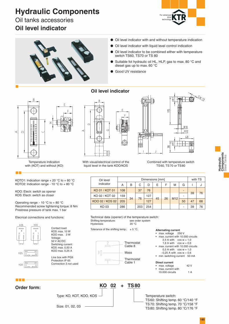
185
KO 01 / KOT 01
KO 02 / KOT 02
KOO 02 / KOS 02
KO 03
A B C D E F M G I J
108
159
205
286
34
37
76
203
76
127
127
254
45 26 M12
-
-
50
-
39
47
39
76
68
76
KO 02 TS80+
For advanceddrive
technology
Hyd
rau
lic
Co
mp
on
ents
Ste
el T
anks
Temperature indicationwith (KOT) and without (KO)
With visual/electrical control of theliquid level in the tank KOO/KOS
Combined with temperature switchTS60, TS70 or TS80
Order form:
Oil level indicator
Dimensions [mm] with TS
Type: KO, KOT, KOO, KOS
Size: 01, 02, 03
Temperature switch:TS60: Shifting temp. 60 °C/140 °FTS70: Shifting temp. 70 °C/158 °FTS80: Shifting temp. 80 °C/176 °F
ThermostatCable 8
Mass
ThermostatCable 1
● Oil level indicator with and without temperature indication
● Oil level indicator with liquid level control indication
● Oil level indicator to be combined either with temperatureswitch TS60, TS70 or TS 80
● Suitable fot hydraulic oil HL, HLP, gas to max. 80 °C anddiesel gas up to max. 60 °C
● Good UV resistance
Oil level indicator
KOTO1: Indication range + 20 °C to + 80 °CKOTO2: Indication range - 10 °C to + 80 °C
KOO: Electr. switch as openerKOS: Electr. switch as closer
Operating range: - 10 °C to + 80 °C Recommended screw tightening torque: 8 NmPrestress pressure of tank max. 1 bar
Elecrical connections and functions:
Contact load:KOS max. 10 WKOO max. 3 WVoltage:50 V AC/DCSwitching current:KOS max. 0,50 AKOO max. 0,25 A
Line box with PG9Protection IP 65Connection 3 not used
Alternating current• max. voltage 250 V• max. current with 10.000 circuits
2,5 A with cos w = 1,01,6 A with cos w = 0,6
• max. current with 10.000 circuits0,5 A with cos w = 1,0
~0,25 A with cos w = 0,6• min. switching current 50 mA
Direct current• max. voltage 42 V• max. current with
10.000 circuits 1 A
Technical data (opener) of the temperature switch:Shifting temperature: see order systemHysteresis 20 °C
Tolerance of the shifting temp.: ± 5 °C.
Hydraulic ComponentsOil tanks accessoriesOil level indicator

186
NVT 22 - 2 - 60 - D3
NVT22 NVT37 NVT45L 220 370 450L1 170 320 400L2 40 40 40
TE - PT-100 - 300
°C Ohm0 100,0010 103,9020 107,7930 111,6740 115,5450 119,4060 123,2470 127,0780 130,8990 134,70100 138,50
For advanceddrive
technology
Hydraulic ComponentsOil tanks accessoriesLevel temperature switch / accessories
Technical data
Orderform:
● Electrical level and temperature control
● Suitable for mineral oils
● Available with 1 or 2 level contacts and with 1 temperature probe
● Electrical switch: decreasing level „opener“increasing temperature „opener“
● Further lengths on request
Plug-in connection D03Three-pole + PE DIN 43650
Plug-in connection DM123pol.
IP65 protectionCable screwing PG11Max. voltage 230 V AC/DC
IP67** protectionCable screwing PG7**Max. voltage 24 V DC** with respective
upper part of plug
Switching tubeOperating pressure max. 1 barOperating temperature max. 80 °CDensity of fluid min. 0,8 kg/dm3
Swimmer SK 161 NBRSwitching tube MSFlange MS
Level contactsFunction NC (opener)Max. voltage operating 230 VMax. current 0,5 AContact load 10 VA
Temperature contactsMax. voltage operating 250 VMax. current switching 2 AMax. contact load 100 VASwitch-back difference 15 K ± 5 K
Table of dimensions
Type NVT Level temperature switch
Size 22 220 mm contact tube
37 370 mm contact tube
45 450 mm contact tube
Voltage D3 max. 230 Volt (Standard)
DM12 max. 24 Volt
Shifting-temperature
O without temperature switch
60 60 °C
70 70 °C
80 80 °C
Type* 1 2 switch contact area H a. L
2 1 switch contact area L and1 temperaure switch
With elastic nylonseal BD R3/4
* Type with level switch on request
Order form: Connection diagram:
Temperature probe - electronicResistance feeler elementLength of dipping sleeve
Inst
alla
tion
dept
hm
in.5
0
Flexibleseal(NBR)
Screwing and dipping sleeve: 1.4571 (stainless steel) – brass on requestAvailable lengths: 100, 200 and 300 mm from stock
(special lengths up to 1000 mm)Operating pressure: 10 bar (dipping sleeve of stainless steel)Operating temperature/ - 40 °C to + 100 °Cmeasuring range:Resistance feeler element: PT-100 Class B DIN/IEC 751Max. S-wire current PT-100: 1 mAPlug: according to DIN 43650 – 3 pl. + PE,
Protection class IP65, cable screwing PG11
Basic values of precisionresistance PT-100
Temperature probe „TE-PT-100“● Control of the operating temperature of the medium
● Value of resistance proportionally changeable to thetemperature
● Continuous signal change
● Flexible seal at the screwed thread head
● Optionally available with transmitter
Technical data
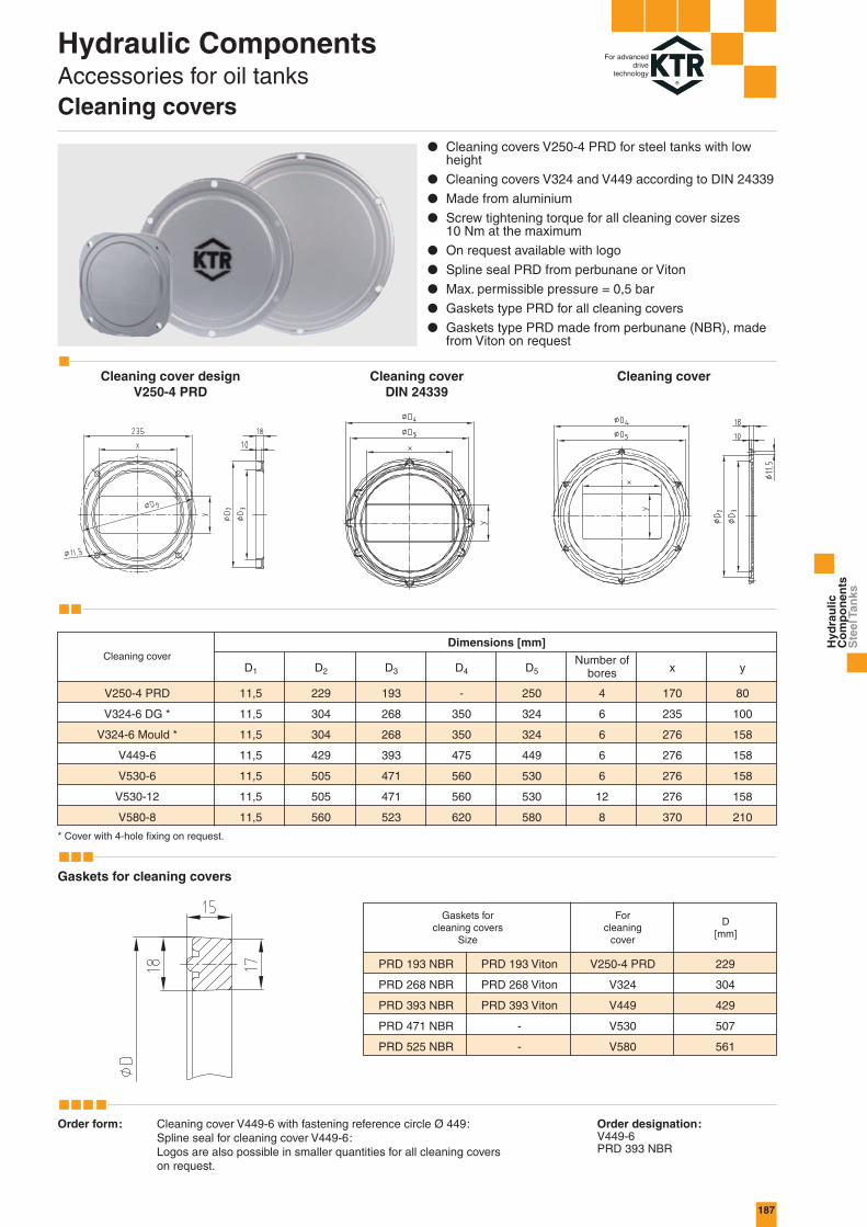
187
D1 D2 D3 D4 D5 x y
11,5
11,5
11,5
11,5
11,5
11,5
11,5
229
304
304
429
505
505
560
193
268
268
393
471
471
523
-
350
350
475
560
560
620
250
324
324
449
530
530
580
4
6
6
6
6
12
8
170
235
276
276
276
276
370
80
100
158
158
158
158
210
D[mm]
PRD 193 NBR
PRD 268 NBR
PRD 393 NBR
PRD 471 NBR
PRD 525 NBR
PRD 193 Viton
PRD 268 Viton
PRD 393 Viton
-
-
V250-4 PRD
V324
V449
V530
V580
229
304
429
507
561
For advanceddrive
technology
Hyd
rau
lic
Co
mp
on
ents
Ste
el T
anks
Order form: Cleaning cover V449-6 with fastening reference circle Ø 449:Spline seal for cleaning cover V449-6:Logos are also possible in smaller quantities for all cleaning coverson request.
Order designation:V449-6PRD 393 NBR
Cleaning coverDIN 24339
Cleaning cover
Cleaning coverDimensions [mm]
V250-4 PRD
V324-6 DG *
V324-6 Mould *
V449-6
V530-6
V530-12
V580-8
Number ofbores
* Cover with 4-hole fixing on request.
Cleaning cover designV250-4 PRD
Gaskets for cleaning covers
Gaskets forcleaning covers
Size
Forcleaning
cover
● Cleaning covers V250-4 PRD for steel tanks with lowheight
● Cleaning covers V324 and V449 according to DIN 24339
● Made from aluminium
● Screw tightening torque for all cleaning cover sizes 10 Nm at the maximum
● On request available with logo
● Spline seal PRD from perbunane or Viton
● Max. permissible pressure = 0,5 bar
● Gaskets type PRD for all cleaning covers
● Gaskets type PRD made from perbunane (NBR), madefrom Viton on request
Hydraulic ComponentsAccessories for oil tanksCleaning covers
