hydraulic conductivity of layered anisotropic media
TRANSCRIPT

6
Hydraulic Conductivity of Layered Anisotropic Media
Stanisław hak Wrocław University of Technology
Poland
1 Introduction
Calculating a flow in a multi-layered medium (material) requires entering geometric
boundaries of all layers boundary conditions in these areas and filtration parameters (Bear
1972) In the case of numerous layers entering these data is very laborious and sometimes
even impossible What we do then is try to model the flow by adopting one medium with
appropriate anisotropic filtration properties In such a case one should decide whether such
an assumption is possible from a theoretical point of view and what parameters of such a
medium should be adopted A full estimation of filtration properties of anisotropic media
requires defining the values of hydraulic conductivity in the direction of the principal axis of
permeability tensor (Bear 1972 Batu 1998 Rogoi 2007) For two-dimensional orthotropic
media including media composed of parallel homogeneous isotropic layers these will be
two values ndash one in parallel direction ( kE ) and the other - perpendicular ( kperp ) to layer
boundary (Snow 1969 Cheng 2000) These values can be determined by performing
permeameter measurements with a forced flow in the above directions If this is not
possible measurements are performed by realising flow in the direction diagonal to
layering and then calculating kE and kperp However this leads to errors in determining these
coefficients The aim of this work is to discuss the causes of these errors and estimate their
value
2 Theoretical basis
The possibility to replace a system of layers with different permeability parameters with one medium with specified parameters should be justified theoretically Based on the flow model adopted for calculations one should clearly state the conditions under which a system of layers can be treated as one medium what parameters should be adopted for such a medium and how to determine them correctly Hence theoretical issues have received a lot of attention so that the problems of flow through layered media can be presented in a possibly full scope which is essential for explaining the theses of the paper
21 Flow through a single layer
Let us consider a simple case of an incompressible fluid flow through a homogeneous and anisotropic aquifer with constant thickness M (Fig 1)
wwwintechopencom
Developments in Hydraulic Conductivity Research
160
Fig 1 Diagram of a flow through a single anisotropic layer
Let us accept that the flow occurs according to Darcys law Let us designate the hydraulic conductivity in a plane tangential to the aquifer floor and roof as kt and in the direction normal to that plane as kn Let the hydraulic head change linearly along line A-A (axis t) according to the equation
A AH at b= + (1)
and along line B-B according to
B BH at b= + (2)
where a bA and bB are constants and A Bb bgt Substituting sin
Ml ϕ= and
tan
Ms ϕ= one can
express hydraulic head drop along l in the form
ϕ ϕ+ minus minus= = minus +0 0( ) ( )sin cosB A A BH t s H t b b
I al M (3)
Filtration direction through an aquifer depends on the direction of hydraulic gradient It can
be determined by calculating the derivativedI
dϕ and comparing it to zero Then
wwwintechopencom
Hydraulic Conductivity of Layered Anisotropic Media
161
arctan A Bb b
aMϕ minus⎛ ⎞= minus⎜ ⎟⎝ ⎠ (4)
The hydraulic head drop for the above angle is
( )( )2
2
2
t
A Bn
A B
I a
b bI
M
b bI a
M
=minus= minusminus= minus +
(5)
while filtration velocity components are
t t
A Bn n
v k a
b bv k
M
= minusminus= (6)
The direction of filtration velocity can be determined from the formula
ϕα ϕϕpart partpart part= = = =part partpart part
sintan tan
cos
n nn n
t tt t
H Hk k
v kn lH Hv kk kt l
(7)
Hence for the discussed example
α ⎛ ⎞minus= minus⎜ ⎟⎝ ⎠arctan n A B
t
k b b
k aM (8)
As we can see from relation (7) the more different the values of hydraulic conductivity kn and kt the bigger the difference between hydraulic gradient direction and filtration velocity
vector If the layer is isotropic angle ϕ will be equal to angle α
22 Flow through layer boundary
If a flow occurs through the boundary between layers with different hydraulic conductivity values streamline refraction occurs Let us consider a flow through the boundary between two layers of soil media orthotropic in two dimensions (Fig 2) Two boundary conditions must be met in this area The hydraulic head H1 in layer 1 should be the same as H2 in layer 2 and the normal velocity component to layer boundary v1n in layer 1 and v2n in layer 2 should be also the same
1 2
1 2n n
H H
v v
== (9)
From the latter condition we obtain
part part=part part1 2
1 2n n
H Hk k
n n (10)
wwwintechopencom
Developments in Hydraulic Conductivity Research
162
Fig 2 Streamline refraction at the boundary of anisotropic layers
But
1 21 2
1 21 2
1 2
tan i tant t
n n
H Hk k
t tH H
k kn n
β βpart partpart part= =part partpart part
(11)
After substituting relations (11) equation (10) assumes the form
1 21 2
1 2tan tan
t t
H Hk k
t tβ βpart partpart part= (12)
Since H1=H2 we obtain
1 1
2 2
tan
tant
t
k
k
ββ= (13)
What emerges is that streamline refraction at the boundary of anisotropic media depends solely on the value of hydraulic conductivity in the direction tangential to layer boundary and does not depend on the values of hydraulic conductivity in the direction normal to layer boundary
23 Flow through a multi-layered medium
Let us consider an incompressible fluid flow through an undeformable soil medium composed of N homogeneous and 2-D orthotropic parallel layers Let us designate the hydraulic conductivity and thickness of the ith layer as kit kin and Mi respectively Let us assume that a steadyndashstate flow diagonal to layering takes place through such a system (Fig 3)
wwwintechopencom
Hydraulic Conductivity of Layered Anisotropic Media
163
Fig 3 Streamlines and filtration direction in a layered medium
Let us also assume that the gradient of hydraulic head along lines A-A and B-B changes according to equations (1) and (2) In such a case streamlines will take the shape of a polygonal chain composed of straight line segments The differences between hydraulic heads along each streamline during the flow through particular layers will have the constant
value ΔHi At layer boundaries according to relation (13) streamline refraction will take place which after adopting the symbols from Fig 3 will be expressed as
( )( )( 1) 1
tan
taniit
i t i
k
k
ββ+ +
= (14)
Water discharge between two streamlines through each layer must be the same For a flow through the ith layer it is
( ) ( )2 2 2 2
2 2 2 2
0
cos cosb
i i i iit in i i it in
H H H Hq k k dt b k k
t n t nβ βpart part part part⎛ ⎞ ⎛ ⎞ ⎛ ⎞ ⎛ ⎞= + = +⎜ ⎟ ⎜ ⎟ ⎜ ⎟ ⎜ ⎟part part part part⎝ ⎠ ⎝ ⎠ ⎝ ⎠ ⎝ ⎠int (15)
Taking into account the relations
( )cosi ii
i
H H
t lϕpart Δ=part (16)
( )sini ii
i
H H
n lϕpart Δ=part (17)
( )cosi
i
i
Ml β= (18)
We obtain the formula
( ) ( ) ( )2 2 2 2cos cos sinii it i in i
i
Hq b k k
lβ ϕ ϕΔ= + (19)
wwwintechopencom
Developments in Hydraulic Conductivity Research
164
For the symbols used in Fig 3 the relation corresponding to equation (13) between βi and ϕi
assumes the form
( ) ( )1tan
tanit
i
in i
k
kϕ β= (20)
On can also prove that
( ) ( )1
1
tan taniti
t
k
kβ β= (21)
Also considering the relations
( ) ( )2
2
11 tan
cosi
i
β β+ = (22)
And
( ) ( ) ( )1
1 1 1
11 1 1
tan
tan tan
n n n
i i t ii i i
n n n
i i i i iti i i
M M k M
a M M k
α β β= = =
= = =
= = =sum sum sumsum sum sum (23)
One can calculate the sum of hydraulic losses along all the flow path through N layers It
comes to
( ) ( ) ( ) ( ) ( )2 2
2 2
1 12 2 2 2
2 221 1
1 1
sin cos sin cossin
N N
it i in iN Ni ii
iN N
i i in
i it i iti i
k M k Mq M
H Hb k
M k M k
α α α αα = == =
= =
⎛ ⎞ ⎛ ⎞⎜ ⎟ ⎜ ⎟⎝ ⎠ ⎝ ⎠Δ = Δ = + +⎛ ⎞ ⎛ ⎞⎜ ⎟ ⎜ ⎟⎝ ⎠ ⎝ ⎠
sum sumsum sum sum sum (24)
In order to determine the hydraulic conductivity of all the layered structure let us replace
the system of layers between the streamlines spaced at b intervals with one homogeneous
layer with the same width b and length l in accordance with Fig 3 If we assume that the
hydraulic conductivity of this layer in the flow direction determined by angle α is ke then
the head loss will be
( )12sin
n
ii
e
q M
Hk b α=Δ = sum
(25)
Comparing the size of hydraulic losses in both cases one obtains the sought formula for the
value of equivalent hydraulic conductivity ke for a flow through a layered medium at any
angle α
wwwintechopencom
Hydraulic Conductivity of Layered Anisotropic Media
165
( ) ( ) ( ) ( )2 2
2 2
2 2 2 21 1
2 21
1 1
1
sin cos sin cos
1
N N
it i in iNi ii
N Ni in
i it i iti i
N
ei
i
k M k MM
kM k M k
kM
α α α α= ==
= =
=
⎛ ⎞ ⎛ ⎞⎜ ⎟ ⎜ ⎟⎝ ⎠ ⎝ ⎠+ +⎛ ⎞ ⎛ ⎞⎜ ⎟ ⎜ ⎟⎝ ⎠ ⎝ ⎠=
sum sumsum sum sumsum
(26)
For a flow parallel to layering (α = 0˚ or α = 180˚) hydraulic conductivity ke will be
designated as kE and according to the above formula it is
1
1
n
it ii
n
ii
k M
k
M
=
=
= sumsumE (27)
while in perpendicular direction (α = 90˚ or α = 270˚) hydraulic conductivity ke will be
designated as kperp and in this case according to formula (26) it is
1
1
n
iin
i
i in
M
kM
k
=perp
=
= sumsum (28)
It is worth emphasizing that equations (27) and (28) can be easily obtained by directly analysing a flow in two directions parallel and perpendicular to layering After substituting relation (27) in equation (26) we obtain
( ) ( ) ( ) ( )2 22 2 2 2
2 21
1
sin cos sin cos1
Ni it in
i in
N
ei
i
M k k
k k k
kM
α α α α=
=
+ +=
sumsum
E E (29)
It follows from equation (29) that in order to determine the equivalent hydraulic
conductivity of a medium composed of anisotropic layers for diagonal direction α it is essential to know all the values of hydraulic conductivity kit and kin of particular layers and their thickness Mi Therefore from the theoretical point of view it is not possible to model a flow through such a structure like that through a single layer On the other hand in the case when particular layers in this structure have isotropic
properties ie one can adopt it in ik k k= = for all the layers relation (29) can be expressed in
the following form (Bear 1972)
( ) ( ) ( ) ( )12 2 2 21
1 1
1 1 1cos sin cos sin
nni
iii i
n n
ei i i
i i
MM
k
k k kM k M
α α α α==perp
= =
= + = +sumsumsum sum E
(30)
wwwintechopencom
Developments in Hydraulic Conductivity Research
166
Then in order to calculate the flow in any direction α it is enough to know the value of hydraulic conductivity for all the layered structure in the direction parallel and perpendicular to the surface constituting layer boundary As expected the form of relation (30) is identical to the function representing hydraulic conductivity in orthotropic soils where two-dimensional anisotropy occurs (Batu 1998 Cheng 2000 Snow 1969 Wieczysty 1982)
( ) ( )2 21 1 1cos sin
e xx yyk k kα α= + (31)
In equation (31) kxx and kyy correspond to the values of hydraulic conductivity in the
principal directions of hydraulic conductivity tensor and xxk k=E while yyk kperp =
If based on equation (30) or (31) one determines the values of ek for various α values then
plotting them in a circle diagram (a graph in polar coordinates) will produce an ellipse It is
referred to as hydraulic conductivity ellipse
24 Angle between hydraulic gradient and filtration velocity
Angle γ between hydraulic gradient (gradH) and filtration velocity v can be determined from the ratio of the dot products of vectors gradH and v to the product of their lengths In the case of a 2D flow and adopting a Cartesian coordinate system whose axes are directed
along the principal axes of hydraulic conductivity tensor angle γ is (Fig 4)
2 22 2
2 2
gradarccos arccos
grad
xx yy
xx yy
H H H Hk k
H x x y y
HH H H H
k kx y x y
γ⎡ ⎤part part part part⎢ ⎥+⎢ ⎥⎛ ⎞ part part part part= = ⎢ ⎥⎜ ⎟⎜ ⎟ ⎢ ⎥⎝ ⎠ ⎛ ⎞ ⎛ ⎞part part part part⎛ ⎞ ⎛ ⎞⎢ ⎥+ +⎜ ⎟ ⎜ ⎟⎜ ⎟ ⎜ ⎟part part part part⎝ ⎠ ⎝ ⎠⎢ ⎥⎝ ⎠ ⎝ ⎠⎣ ⎦
v
v
i (32)
where kxx and kyy denote the values of hydraulic conductivity tensor k
0
0xx
yy
kk
k
⎛ ⎞= ⎜ ⎟⎜ ⎟⎝ ⎠ (33)
Remembering that
( )tanyy
xx
Hk
y
Hk
x
αpartpart= partpart
(34)
one obtains
( ) ( )( ) ( )
( ) ( )( ) ( )
2 2 2 2
2 2 2 2 2 2 2
cos sin cos sinarccos arccos
cos sin cos sin
yy xx
yy xx
k k
k k
α α α λ αγ α α α λ α⎛ ⎞ ⎛ ⎞+ +⎜ ⎟ ⎜ ⎟= =⎜ ⎟ ⎜ ⎟+ +⎝ ⎠⎝ ⎠ (35)
wwwintechopencom
Hydraulic Conductivity of Layered Anisotropic Media
167
Fig 4 Direction differences between hydraulic gradient and filtration velocity
where α denotes the angle between velocity vector and the principal axis of hydraulic conductivity tensor along which value k reaches the maximum values From the above relation one can determine the value of angle α for which angle γ has the
maximum value In order to do this one must determine the derivative d
d
γα and compare it
to zero The angle determined in this way is
1
arctan arctanyy
xx
k
kα λ= plusmn = plusmn (36)
Assuming that kxxgtkyy xx
yy
k
kλ = denotes anisotropy factor For layered media composed of
homogeneous isotropic and parallel layers value kxx corresponds to kE and value kyy ndash to kperp
3 Problems with determining the hydraulic conductivity of anisotropic media
Defining water permeability of anisotropic media requires determining values of hydraulic
conductivity in the direction of principal axes of hydraulic conductivity (Renard 2001
Mozely et al 1996) For media characterized by two-dimensional orthotropy including
layered media these will be two values ndash one in parallel direction and the other ndash
perpendicular to layering In accordance with equation (30) determining hydraulic
conductivity in these directions is possible based on tests of hydraulic conductivity ke for
any two known angles α Then one obtains two equations with two unknowns kE and kperp
When determining these values one can later calculate equivalent hydraulic conductivity ke
in any direction α However if there are any difficulties defining angles α for which water
permeability measurements are performed kE and kperp can be determined by performing a
larger number of measurements for various angles (at least three different angles) and then
matching the obtained results with the ellipse equation (Cheng 2000)
wwwintechopencom
Developments in Hydraulic Conductivity Research
168
This is the theory However determining hydraulic conductivity of layered media in permeameters involves additional problems Analysing relation (35) one can observe that the angle between gradH and v is equal to zero ie both directions coincide only when
angle α is equal to 0 90 180 and 270 degrees then if the flow occurs in the direction parallel or perpendicular to layering When performing measurements along these directions one does not make additional errors resulting from anisotropy However if such a measurement is not possible (eg samples are obtained from hole coring and the hole axis is diagonal to layering) determining the value of hydraulic conductivity in the direction diagonal to layering entails an error It results from the fact that during measurements inside permeameters the appropriate geometric shapes of the sample the proper size and the difference between filtration velocity v and gradH are not maintained Geometric dimensions should allow for maintaining the angle between filtration direction
and the plane through which water flows to the sample and the lateral surfaces of the
sample The inflow and outflow surfaces should be perpendicular to the gradient of
hydraulic head and the lateral surfaces ndash parallel to streamlines composed of straight line
segments (Fig 3)
Meeting the above conditions is very difficult technically moreover it would require prior
knowledge of filtration parameters of particular layers of the medium The knowledge of
these parameters would enable theoretical calculation of hydraulic conductivity without a
need to analyse all the layer structure If we assume however that we do not know these
parameters maintaining appropriate shapes of the sample is not possible In such a case as
an approximation of the abovementioned theoretical solution reflecting a flow diagonal to
layering one can adopt a flow through a medium sample whose geometric dimensions and
flow conditions are consistent with the idea presented in Fig 5 One should remember here
that the cross-section of the sample in the direction perpendicular to filtration direction
should be a rectangle
Fig 5 Diagram of the pattern of adopting a geometric shape for a layered medium sample for permeameter analysis
Unfortunately when performing permeameter tests on samples with the shape presented in
Fig 5 one cannot avoid errors in determination of hydraulic conductivity
wwwintechopencom
Hydraulic Conductivity of Layered Anisotropic Media
169
4 Model calculations
In order to estimate error values connected with determining hydraulic conductivity of
layered media tested in a permeameter water flow through an imaginary soil medium
composed of layers with known properties was calculated The calculations consisted of a
numerical solution of a flow through a specific arrangement of layers in a permeameter and
then defining equivalent hydraulic conductivity The hydraulic conductivity defined in this
way was then compared to theoretically calculated hydraulic conductivity of a layered
structure corresponding to the layer pattern in the permeameter
41 Characteristics of the medium
Model calculations were performed on a soil sample composed of five homogeneous and
isotropic layers with constant thickness (Fig 3) The thickness of particular layers Mi and
hydraulic conductivity ki are presented in Tab 1
Mi ki kE kperp λ Layer No
cm ms-1 ms-1 ms-1 -
1 21 7010-4
2 20 1010-5
3 19 6010-6
4 20 8010-5
5 31 2010-4
20610-4 19810-5 1037
Table 1 Basic properties of a layered medium
For such a layer pattern formula (30) was used to calculate theoretical values of hydraulic
conductivity ke(t) and the angle between vectors gradH and v for different values of angle α
between filtration velocity and the direction of principal axis t Based on the obtained
results hydraulic conductivity ellipse ( ek ) and the values of angles between gradH and
filtration velocity v (angles γ) depending on filtration direction were drawn (Figs 6 and 7) Table 1 also contains calculated hydraulic conductivity values for all the layered structure
in the direction parallel and perpendicular to layer boundaries as well as the anisotropy
factor
42 Numerical solution of permeameter flow
The problem of permeameter flow was solved based on Laplacersquos equation assuming the steady flow of an incompressible fluid through an undeformed medium On the surfaces forming the filtration area boundary boundary conditions were adopted according to Fig 5 while on the boundary of layers with different water permeability Hi = Hi+1 and vni = vni+1 were adopted with Hi Hi+1 denoting the hydraulic heads and vni and vni+1 ndash filtration velocity components normal to the boundary of ith and i+1th layers All the filtration area was divided into 110x14 blocks The calculations were performed with finite difference method in Excel spreadsheet using Gauss-Seidel iteration The calculation results for
different angles α are shown in Tab 2
wwwintechopencom
Developments in Hydraulic Conductivity Research
170
0000
0002
0004
0006
0008
0010
0012
0014
0016
90
8070
60
50
40
30
20
10
0
350
340
330
320
310
300
290280
270
260250
240
230
220
210
200
190
180
170
160
150
140
130
120
110100
k e
k n
k t
t
n
Fig 6 Hydraulic conductivity ellipse
0
10
20
30
40
50
60
90
8070
60
50
40
30
20
10
0
350
340
330
320
310
300
290280
270
260250
240
230
220
210
200
190
180
170
160
150
140
130
120
110100 γ o
t
n
Fig 7 Angle between hydraulic gradient and filtration velocity depending on filtration direction
wwwintechopencom
Hydraulic Conductivity of Layered Anisotropic Media
171
α γ ke(t) ke(num) ( )e t
k
k
Δ
sr
Q
Q
Δ No
˚ ˚ ms-1 ms-1
1 0 000 20610-4 20610-4 000 000
2 45 3949 36110-5 23110-5 3615 -003
3 50 3537 31610-5 21510-5 3201 382
4 55 3114 28210-5 21310-5 2439 304
5 60 2681 25610-5 21110-5 1740 243
6 65 2243 23610-5 20910-5 1145 168
7 70 1799 22210-5 20710-5 664 109
8 75 1352 21110-5 20410-5 318 061
9 80 903 20410-5 20110-5 108 027
10 85 452 20010-5 19910-5 017 006
11 90 000 19810-5 19810-5 009 000
Table 2 Results of numerical calculations of angle γ between hydraulic gradient and filtration velocity and equivalent hydraulic conductivity ke(num)
It contains theoretically and numerically defined values of equivalent hydraulic conductivity (ke(t) and ke(num)) theoretical values of angles γ between gradH and v error in numerical determination of conductivity in relation to the theoretical value
( ) ( )
( ) ( )
100e t e num
e t e t
k kk
k k
minusΔ = as well as error values ( ) 10005
w d
sr w d
Q Q Q
Q Q Q
Δ minus sdot+= resulting from a
numerical comparison of the quantity of water flowing into (Qd) and out of (Qw) the analysed sample This error was regarded as representative for estimating the accuracy of numerical calculation results
43 Error of hydraulic conductivity determination
In order to estimate the error in determining hydraulic conductivity of a layered medium it
was assumed that the analyses had been performed in a permeameter The tests were
carried out on a layered medium presented in Fig 5 for two flow directions in relation to the
principal axis of permeability tensor One direction corresponded to angle α of 45˚ while
the other - 80˚ The values of equivalent hydraulic conductivity determined correctly
through research should be consistent with Tab 2 and amount to 23110-5 ms-1 and 20110-5
ms-1 respectively Using them later to calculate the hydraulic conductivity in the direction
of the principal axis of permeability tensor from formula (30) one obtains kE = 27510-5 ms-1
and kperp = 19910-5 ms-1 The values calculated in this way were compared with the
theoretical properties of a layered medium presented in Tab1 On can see from the
comparison that the values of kperp are only slightly different (the theoretical value is 198 10-5
m s-1) while in the case of kE the difference is very distinct reaching 75 times One should
also emphasize that such a big difference between these results is not caused by the low
accuracy of numerical flow calculations This is proved by a very small difference in the
discharge of water flowing into and out of the sample no more than 03 (Tab 2)
wwwintechopencom
Developments in Hydraulic Conductivity Research
172
The error in hydraulic conductivity determination in a permeameter may be also caused by
the order of layering In order to estimate its value numerical calculations were performed
for the adopted flow through a layered medium composed of the same layers but arranged
in a different order One should emphasize that according to formula (30) the theoretical
value of equivalent hydraulic conductivity kt does not depend on the layering order The
calculation results for a flow at the angle α = 45˚ and for four layering variants are shown in
Tab 3
ke(t) ke(num) ( )e t
k
k
Δ
sr
Q
Q
Δ Variant
No Layering
order ms-1 ms-1
1 5-1-2-3-4-5 23110-5 3615 -0027
2 5-3-2-4-1-5 21610-5 4014 -0058
3 5-1-4-2-3-5 22710-5 3707 0033
4 5-2-4-3-1-5
36110-5
25510-5 2954 0012
Tab 3 Calculation results of hydraulic conductivity of a layered medium for various layering orders
One can see that depending on the considered variant different results are obtained and
anisotropy-related determination error is contained within wide limits In the analysed
examples it oscillates between 30 and over 40 in relation to the theoretical value In order
to illustrate the causes of differences in hydraulic conductivity calculations of streamline
pattern were also performed For the layering in variants 2 and 4 streamline patterns are
shown in Figs 6 and 7
Fig 6 Streamlines in a sample for layering variant 2
wwwintechopencom
Hydraulic Conductivity of Layered Anisotropic Media
173
0
5
10
15
20
25
-20 0 20 40 60 80 100 120 140 160 180
k5k2 k4 k3
k1 k5
Fig 7 Streamlines in a sample for layering variant 4
A distinct difference in streamline patterns is noticeable Certainly the streamline pattern is basically different from the theoretical streamlines shown in Fig 3 which are polygonal chains composed of straight line segments
5 Conclusion
The presented theoretical discussion has demonstrated that flows in layered media composed
of homogeneous and anisotropic layers cannot be modelled as flows in a homogeneous
medium However it is possible in the case of a structure composed of parallel layers
characterised by homogeneity and orthotropy in two dimensions A flow in such a structure
can be modelled as a flow in a single anisotropic layer In such a case one does not have to
know the permeability parameters and the thickness of particular layers In order to calculate
the flow it is then enough to know the hydraulic conductivity in the direction parallel and
perpendicular to layering These values can be determined theoretically by analysing a flow
through such a layered structure in any two directions to the boundary surfaces of the layers
However the calculation results point to a possibility of vital errors occurring while
determining the permeability of layered media in a permeameter This regards those tests
where flow occurs in the direction diagonal to layering The occurrence of major determination
errors is connected with a failure to maintain the appropriate directions of gradH and v and
the proper geometric shape of the sample in a permeameter The value of those errors depends
on the value of anisotropy factor λ and the angular difference between gradH and v In the
performed model calculations of a flow through a layered medium with anisotropy factor
λ = 1037 the obtained value of hydraulic conductivity in the direction perpendicular to layer
boundary was very close to the theoretical one while in the parallel direction it was 75 times
underrated Clearly then such analyses result in very serious underrating of anisotropy factor
The conducted calculations also reveal a considerable influence of layering order on the
determination results of hydraulic conductivity in a permeameter The differences obtained
from model calculations oscillated between c 30 to 40 in relation to the theoretical value
wwwintechopencom
Developments in Hydraulic Conductivity Research
174
To sum up one should clearly state that the correct determination results of hydraulic conductivity of layered media can be obtained by forcing a flow in the direction parallel and perpendicular to layering Any departures from this rule may lead to very large determination errors
6 References
Batu V (1998) Aquifer hydraulics A comprehensive quide to hydrogeologic data analysis John Wiley amp Sons ISBN 0-471-18502-7 New York
Bear J (1972) Dynamics of Fluids in Porous Media Dover Publications ISBN 0-486-65675-6 Cheng A (2000) Multilayered aquifer systems Fundamentals and applications Marcel Dekker
Inc ISBN 0-8247-9875-9 New York Basel Mozely PS amp Davis JM (1996) Relationship between oriented calcite concretions and
permeability correlation structure in alluvial aquifer Sierra Ladrones Formation New Mexiko Journal of Sedimentary Research Vol 66 No 1 (January 1996) pp (11-16) ISSN 1527-1404
Renard Ph Genty A Stauffer F (2001) Laboratory determination of full permeability tensor Journal of Geophysical Research Vol 106 No B11 (November 2001) pp 26443-26452 ISSN 0148-0227
Rogoi M (2007) Dynamika woacuted podziemnych GIG ISBN 978-83-87610-97-5 Katowice Snow D T (1969) Anisotropic permeability of fractured media Water Resour Res 5(6)
1273-1289 ISSN 0043-1397
wwwintechopencom
Developments in Hydraulic Conductivity ResearchEdited by Dr Oagile Dikinya
ISBN 978-953-307-470-2Hard cover 270 pagesPublisher InTechPublished online 28 February 2011Published in print edition February 2011
InTech EuropeUniversity Campus STeP Ri Slavka Krautzeka 83A 51000 Rijeka Croatia Phone +385 (51) 770 447 Fax +385 (51) 686 166wwwintechopencom
InTech ChinaUnit 405 Office Block Hotel Equatorial Shanghai No65 Yan An Road (West) Shanghai 200040 China Phone +86-21-62489820 Fax +86-21-62489821
This book provides the state of the art of the investigation and the in-depth analysis of hydraulic conductivityfrom the theoretical to semi-empirical models perspective as well as policy development associated withmanagement of land resources emanating from drainage-problem soils A group of international expertscontributed to the development of this book It is envisaged that this thought provoking book will excite andappeal to academics engineers researchers and University students who seek to explore the breadth and in-depth knowledge about hydraulic conductivity Investigation into hydraulic conductivity is important to theunderstanding of the movement of solutes and water in the terrestrial environment Transport of these fluidshas various implications on the ecology and quality of environment and subsequently sustenance of livelihoodsof the increasing world population In particular water flow in the vadose zone is of fundamental importance togeoscientists soil scientists hydrogeologists and hydrologists and allied professionals
How to referenceIn order to correctly reference this scholarly work feel free to copy and paste the following
Stanisław Żak (2011) Hydraulic Conductivity of Layered Anisotropic Media Developments in HydraulicConductivity Research Dr Oagile Dikinya (Ed) ISBN 978-953-307-470-2 InTech Available fromhttpwwwintechopencombooksdevelopments-in-hydraulic-conductivity-researchhydraulic-conductivity-of-layered-anisotropic-media
copy 2011 The Author(s) Licensee IntechOpen This chapter is distributedunder the terms of the Creative Commons Attribution-NonCommercial-ShareAlike-30 License which permits use distribution and reproduction fornon-commercial purposes provided the original is properly cited andderivative works building on this content are distributed under the samelicense

Developments in Hydraulic Conductivity Research
160
Fig 1 Diagram of a flow through a single anisotropic layer
Let us accept that the flow occurs according to Darcys law Let us designate the hydraulic conductivity in a plane tangential to the aquifer floor and roof as kt and in the direction normal to that plane as kn Let the hydraulic head change linearly along line A-A (axis t) according to the equation
A AH at b= + (1)
and along line B-B according to
B BH at b= + (2)
where a bA and bB are constants and A Bb bgt Substituting sin
Ml ϕ= and
tan
Ms ϕ= one can
express hydraulic head drop along l in the form
ϕ ϕ+ minus minus= = minus +0 0( ) ( )sin cosB A A BH t s H t b b
I al M (3)
Filtration direction through an aquifer depends on the direction of hydraulic gradient It can
be determined by calculating the derivativedI
dϕ and comparing it to zero Then
wwwintechopencom
Hydraulic Conductivity of Layered Anisotropic Media
161
arctan A Bb b
aMϕ minus⎛ ⎞= minus⎜ ⎟⎝ ⎠ (4)
The hydraulic head drop for the above angle is
( )( )2
2
2
t
A Bn
A B
I a
b bI
M
b bI a
M
=minus= minusminus= minus +
(5)
while filtration velocity components are
t t
A Bn n
v k a
b bv k
M
= minusminus= (6)
The direction of filtration velocity can be determined from the formula
ϕα ϕϕpart partpart part= = = =part partpart part
sintan tan
cos
n nn n
t tt t
H Hk k
v kn lH Hv kk kt l
(7)
Hence for the discussed example
α ⎛ ⎞minus= minus⎜ ⎟⎝ ⎠arctan n A B
t
k b b
k aM (8)
As we can see from relation (7) the more different the values of hydraulic conductivity kn and kt the bigger the difference between hydraulic gradient direction and filtration velocity
vector If the layer is isotropic angle ϕ will be equal to angle α
22 Flow through layer boundary
If a flow occurs through the boundary between layers with different hydraulic conductivity values streamline refraction occurs Let us consider a flow through the boundary between two layers of soil media orthotropic in two dimensions (Fig 2) Two boundary conditions must be met in this area The hydraulic head H1 in layer 1 should be the same as H2 in layer 2 and the normal velocity component to layer boundary v1n in layer 1 and v2n in layer 2 should be also the same
1 2
1 2n n
H H
v v
== (9)
From the latter condition we obtain
part part=part part1 2
1 2n n
H Hk k
n n (10)
wwwintechopencom
Developments in Hydraulic Conductivity Research
162
Fig 2 Streamline refraction at the boundary of anisotropic layers
But
1 21 2
1 21 2
1 2
tan i tant t
n n
H Hk k
t tH H
k kn n
β βpart partpart part= =part partpart part
(11)
After substituting relations (11) equation (10) assumes the form
1 21 2
1 2tan tan
t t
H Hk k
t tβ βpart partpart part= (12)
Since H1=H2 we obtain
1 1
2 2
tan
tant
t
k
k
ββ= (13)
What emerges is that streamline refraction at the boundary of anisotropic media depends solely on the value of hydraulic conductivity in the direction tangential to layer boundary and does not depend on the values of hydraulic conductivity in the direction normal to layer boundary
23 Flow through a multi-layered medium
Let us consider an incompressible fluid flow through an undeformable soil medium composed of N homogeneous and 2-D orthotropic parallel layers Let us designate the hydraulic conductivity and thickness of the ith layer as kit kin and Mi respectively Let us assume that a steadyndashstate flow diagonal to layering takes place through such a system (Fig 3)
wwwintechopencom
Hydraulic Conductivity of Layered Anisotropic Media
163
Fig 3 Streamlines and filtration direction in a layered medium
Let us also assume that the gradient of hydraulic head along lines A-A and B-B changes according to equations (1) and (2) In such a case streamlines will take the shape of a polygonal chain composed of straight line segments The differences between hydraulic heads along each streamline during the flow through particular layers will have the constant
value ΔHi At layer boundaries according to relation (13) streamline refraction will take place which after adopting the symbols from Fig 3 will be expressed as
( )( )( 1) 1
tan
taniit
i t i
k
k
ββ+ +
= (14)
Water discharge between two streamlines through each layer must be the same For a flow through the ith layer it is
( ) ( )2 2 2 2
2 2 2 2
0
cos cosb
i i i iit in i i it in
H H H Hq k k dt b k k
t n t nβ βpart part part part⎛ ⎞ ⎛ ⎞ ⎛ ⎞ ⎛ ⎞= + = +⎜ ⎟ ⎜ ⎟ ⎜ ⎟ ⎜ ⎟part part part part⎝ ⎠ ⎝ ⎠ ⎝ ⎠ ⎝ ⎠int (15)
Taking into account the relations
( )cosi ii
i
H H
t lϕpart Δ=part (16)
( )sini ii
i
H H
n lϕpart Δ=part (17)
( )cosi
i
i
Ml β= (18)
We obtain the formula
( ) ( ) ( )2 2 2 2cos cos sinii it i in i
i
Hq b k k
lβ ϕ ϕΔ= + (19)
wwwintechopencom
Developments in Hydraulic Conductivity Research
164
For the symbols used in Fig 3 the relation corresponding to equation (13) between βi and ϕi
assumes the form
( ) ( )1tan
tanit
i
in i
k
kϕ β= (20)
On can also prove that
( ) ( )1
1
tan taniti
t
k
kβ β= (21)
Also considering the relations
( ) ( )2
2
11 tan
cosi
i
β β+ = (22)
And
( ) ( ) ( )1
1 1 1
11 1 1
tan
tan tan
n n n
i i t ii i i
n n n
i i i i iti i i
M M k M
a M M k
α β β= = =
= = =
= = =sum sum sumsum sum sum (23)
One can calculate the sum of hydraulic losses along all the flow path through N layers It
comes to
( ) ( ) ( ) ( ) ( )2 2
2 2
1 12 2 2 2
2 221 1
1 1
sin cos sin cossin
N N
it i in iN Ni ii
iN N
i i in
i it i iti i
k M k Mq M
H Hb k
M k M k
α α α αα = == =
= =
⎛ ⎞ ⎛ ⎞⎜ ⎟ ⎜ ⎟⎝ ⎠ ⎝ ⎠Δ = Δ = + +⎛ ⎞ ⎛ ⎞⎜ ⎟ ⎜ ⎟⎝ ⎠ ⎝ ⎠
sum sumsum sum sum sum (24)
In order to determine the hydraulic conductivity of all the layered structure let us replace
the system of layers between the streamlines spaced at b intervals with one homogeneous
layer with the same width b and length l in accordance with Fig 3 If we assume that the
hydraulic conductivity of this layer in the flow direction determined by angle α is ke then
the head loss will be
( )12sin
n
ii
e
q M
Hk b α=Δ = sum
(25)
Comparing the size of hydraulic losses in both cases one obtains the sought formula for the
value of equivalent hydraulic conductivity ke for a flow through a layered medium at any
angle α
wwwintechopencom
Hydraulic Conductivity of Layered Anisotropic Media
165
( ) ( ) ( ) ( )2 2
2 2
2 2 2 21 1
2 21
1 1
1
sin cos sin cos
1
N N
it i in iNi ii
N Ni in
i it i iti i
N
ei
i
k M k MM
kM k M k
kM
α α α α= ==
= =
=
⎛ ⎞ ⎛ ⎞⎜ ⎟ ⎜ ⎟⎝ ⎠ ⎝ ⎠+ +⎛ ⎞ ⎛ ⎞⎜ ⎟ ⎜ ⎟⎝ ⎠ ⎝ ⎠=
sum sumsum sum sumsum
(26)
For a flow parallel to layering (α = 0˚ or α = 180˚) hydraulic conductivity ke will be
designated as kE and according to the above formula it is
1
1
n
it ii
n
ii
k M
k
M
=
=
= sumsumE (27)
while in perpendicular direction (α = 90˚ or α = 270˚) hydraulic conductivity ke will be
designated as kperp and in this case according to formula (26) it is
1
1
n
iin
i
i in
M
kM
k
=perp
=
= sumsum (28)
It is worth emphasizing that equations (27) and (28) can be easily obtained by directly analysing a flow in two directions parallel and perpendicular to layering After substituting relation (27) in equation (26) we obtain
( ) ( ) ( ) ( )2 22 2 2 2
2 21
1
sin cos sin cos1
Ni it in
i in
N
ei
i
M k k
k k k
kM
α α α α=
=
+ +=
sumsum
E E (29)
It follows from equation (29) that in order to determine the equivalent hydraulic
conductivity of a medium composed of anisotropic layers for diagonal direction α it is essential to know all the values of hydraulic conductivity kit and kin of particular layers and their thickness Mi Therefore from the theoretical point of view it is not possible to model a flow through such a structure like that through a single layer On the other hand in the case when particular layers in this structure have isotropic
properties ie one can adopt it in ik k k= = for all the layers relation (29) can be expressed in
the following form (Bear 1972)
( ) ( ) ( ) ( )12 2 2 21
1 1
1 1 1cos sin cos sin
nni
iii i
n n
ei i i
i i
MM
k
k k kM k M
α α α α==perp
= =
= + = +sumsumsum sum E
(30)
wwwintechopencom
Developments in Hydraulic Conductivity Research
166
Then in order to calculate the flow in any direction α it is enough to know the value of hydraulic conductivity for all the layered structure in the direction parallel and perpendicular to the surface constituting layer boundary As expected the form of relation (30) is identical to the function representing hydraulic conductivity in orthotropic soils where two-dimensional anisotropy occurs (Batu 1998 Cheng 2000 Snow 1969 Wieczysty 1982)
( ) ( )2 21 1 1cos sin
e xx yyk k kα α= + (31)
In equation (31) kxx and kyy correspond to the values of hydraulic conductivity in the
principal directions of hydraulic conductivity tensor and xxk k=E while yyk kperp =
If based on equation (30) or (31) one determines the values of ek for various α values then
plotting them in a circle diagram (a graph in polar coordinates) will produce an ellipse It is
referred to as hydraulic conductivity ellipse
24 Angle between hydraulic gradient and filtration velocity
Angle γ between hydraulic gradient (gradH) and filtration velocity v can be determined from the ratio of the dot products of vectors gradH and v to the product of their lengths In the case of a 2D flow and adopting a Cartesian coordinate system whose axes are directed
along the principal axes of hydraulic conductivity tensor angle γ is (Fig 4)
2 22 2
2 2
gradarccos arccos
grad
xx yy
xx yy
H H H Hk k
H x x y y
HH H H H
k kx y x y
γ⎡ ⎤part part part part⎢ ⎥+⎢ ⎥⎛ ⎞ part part part part= = ⎢ ⎥⎜ ⎟⎜ ⎟ ⎢ ⎥⎝ ⎠ ⎛ ⎞ ⎛ ⎞part part part part⎛ ⎞ ⎛ ⎞⎢ ⎥+ +⎜ ⎟ ⎜ ⎟⎜ ⎟ ⎜ ⎟part part part part⎝ ⎠ ⎝ ⎠⎢ ⎥⎝ ⎠ ⎝ ⎠⎣ ⎦
v
v
i (32)
where kxx and kyy denote the values of hydraulic conductivity tensor k
0
0xx
yy
kk
k
⎛ ⎞= ⎜ ⎟⎜ ⎟⎝ ⎠ (33)
Remembering that
( )tanyy
xx
Hk
y
Hk
x
αpartpart= partpart
(34)
one obtains
( ) ( )( ) ( )
( ) ( )( ) ( )
2 2 2 2
2 2 2 2 2 2 2
cos sin cos sinarccos arccos
cos sin cos sin
yy xx
yy xx
k k
k k
α α α λ αγ α α α λ α⎛ ⎞ ⎛ ⎞+ +⎜ ⎟ ⎜ ⎟= =⎜ ⎟ ⎜ ⎟+ +⎝ ⎠⎝ ⎠ (35)
wwwintechopencom
Hydraulic Conductivity of Layered Anisotropic Media
167
Fig 4 Direction differences between hydraulic gradient and filtration velocity
where α denotes the angle between velocity vector and the principal axis of hydraulic conductivity tensor along which value k reaches the maximum values From the above relation one can determine the value of angle α for which angle γ has the
maximum value In order to do this one must determine the derivative d
d
γα and compare it
to zero The angle determined in this way is
1
arctan arctanyy
xx
k
kα λ= plusmn = plusmn (36)
Assuming that kxxgtkyy xx
yy
k
kλ = denotes anisotropy factor For layered media composed of
homogeneous isotropic and parallel layers value kxx corresponds to kE and value kyy ndash to kperp
3 Problems with determining the hydraulic conductivity of anisotropic media
Defining water permeability of anisotropic media requires determining values of hydraulic
conductivity in the direction of principal axes of hydraulic conductivity (Renard 2001
Mozely et al 1996) For media characterized by two-dimensional orthotropy including
layered media these will be two values ndash one in parallel direction and the other ndash
perpendicular to layering In accordance with equation (30) determining hydraulic
conductivity in these directions is possible based on tests of hydraulic conductivity ke for
any two known angles α Then one obtains two equations with two unknowns kE and kperp
When determining these values one can later calculate equivalent hydraulic conductivity ke
in any direction α However if there are any difficulties defining angles α for which water
permeability measurements are performed kE and kperp can be determined by performing a
larger number of measurements for various angles (at least three different angles) and then
matching the obtained results with the ellipse equation (Cheng 2000)
wwwintechopencom
Developments in Hydraulic Conductivity Research
168
This is the theory However determining hydraulic conductivity of layered media in permeameters involves additional problems Analysing relation (35) one can observe that the angle between gradH and v is equal to zero ie both directions coincide only when
angle α is equal to 0 90 180 and 270 degrees then if the flow occurs in the direction parallel or perpendicular to layering When performing measurements along these directions one does not make additional errors resulting from anisotropy However if such a measurement is not possible (eg samples are obtained from hole coring and the hole axis is diagonal to layering) determining the value of hydraulic conductivity in the direction diagonal to layering entails an error It results from the fact that during measurements inside permeameters the appropriate geometric shapes of the sample the proper size and the difference between filtration velocity v and gradH are not maintained Geometric dimensions should allow for maintaining the angle between filtration direction
and the plane through which water flows to the sample and the lateral surfaces of the
sample The inflow and outflow surfaces should be perpendicular to the gradient of
hydraulic head and the lateral surfaces ndash parallel to streamlines composed of straight line
segments (Fig 3)
Meeting the above conditions is very difficult technically moreover it would require prior
knowledge of filtration parameters of particular layers of the medium The knowledge of
these parameters would enable theoretical calculation of hydraulic conductivity without a
need to analyse all the layer structure If we assume however that we do not know these
parameters maintaining appropriate shapes of the sample is not possible In such a case as
an approximation of the abovementioned theoretical solution reflecting a flow diagonal to
layering one can adopt a flow through a medium sample whose geometric dimensions and
flow conditions are consistent with the idea presented in Fig 5 One should remember here
that the cross-section of the sample in the direction perpendicular to filtration direction
should be a rectangle
Fig 5 Diagram of the pattern of adopting a geometric shape for a layered medium sample for permeameter analysis
Unfortunately when performing permeameter tests on samples with the shape presented in
Fig 5 one cannot avoid errors in determination of hydraulic conductivity
wwwintechopencom
Hydraulic Conductivity of Layered Anisotropic Media
169
4 Model calculations
In order to estimate error values connected with determining hydraulic conductivity of
layered media tested in a permeameter water flow through an imaginary soil medium
composed of layers with known properties was calculated The calculations consisted of a
numerical solution of a flow through a specific arrangement of layers in a permeameter and
then defining equivalent hydraulic conductivity The hydraulic conductivity defined in this
way was then compared to theoretically calculated hydraulic conductivity of a layered
structure corresponding to the layer pattern in the permeameter
41 Characteristics of the medium
Model calculations were performed on a soil sample composed of five homogeneous and
isotropic layers with constant thickness (Fig 3) The thickness of particular layers Mi and
hydraulic conductivity ki are presented in Tab 1
Mi ki kE kperp λ Layer No
cm ms-1 ms-1 ms-1 -
1 21 7010-4
2 20 1010-5
3 19 6010-6
4 20 8010-5
5 31 2010-4
20610-4 19810-5 1037
Table 1 Basic properties of a layered medium
For such a layer pattern formula (30) was used to calculate theoretical values of hydraulic
conductivity ke(t) and the angle between vectors gradH and v for different values of angle α
between filtration velocity and the direction of principal axis t Based on the obtained
results hydraulic conductivity ellipse ( ek ) and the values of angles between gradH and
filtration velocity v (angles γ) depending on filtration direction were drawn (Figs 6 and 7) Table 1 also contains calculated hydraulic conductivity values for all the layered structure
in the direction parallel and perpendicular to layer boundaries as well as the anisotropy
factor
42 Numerical solution of permeameter flow
The problem of permeameter flow was solved based on Laplacersquos equation assuming the steady flow of an incompressible fluid through an undeformed medium On the surfaces forming the filtration area boundary boundary conditions were adopted according to Fig 5 while on the boundary of layers with different water permeability Hi = Hi+1 and vni = vni+1 were adopted with Hi Hi+1 denoting the hydraulic heads and vni and vni+1 ndash filtration velocity components normal to the boundary of ith and i+1th layers All the filtration area was divided into 110x14 blocks The calculations were performed with finite difference method in Excel spreadsheet using Gauss-Seidel iteration The calculation results for
different angles α are shown in Tab 2
wwwintechopencom
Developments in Hydraulic Conductivity Research
170
0000
0002
0004
0006
0008
0010
0012
0014
0016
90
8070
60
50
40
30
20
10
0
350
340
330
320
310
300
290280
270
260250
240
230
220
210
200
190
180
170
160
150
140
130
120
110100
k e
k n
k t
t
n
Fig 6 Hydraulic conductivity ellipse
0
10
20
30
40
50
60
90
8070
60
50
40
30
20
10
0
350
340
330
320
310
300
290280
270
260250
240
230
220
210
200
190
180
170
160
150
140
130
120
110100 γ o
t
n
Fig 7 Angle between hydraulic gradient and filtration velocity depending on filtration direction
wwwintechopencom
Hydraulic Conductivity of Layered Anisotropic Media
171
α γ ke(t) ke(num) ( )e t
k
k
Δ
sr
Q
Q
Δ No
˚ ˚ ms-1 ms-1
1 0 000 20610-4 20610-4 000 000
2 45 3949 36110-5 23110-5 3615 -003
3 50 3537 31610-5 21510-5 3201 382
4 55 3114 28210-5 21310-5 2439 304
5 60 2681 25610-5 21110-5 1740 243
6 65 2243 23610-5 20910-5 1145 168
7 70 1799 22210-5 20710-5 664 109
8 75 1352 21110-5 20410-5 318 061
9 80 903 20410-5 20110-5 108 027
10 85 452 20010-5 19910-5 017 006
11 90 000 19810-5 19810-5 009 000
Table 2 Results of numerical calculations of angle γ between hydraulic gradient and filtration velocity and equivalent hydraulic conductivity ke(num)
It contains theoretically and numerically defined values of equivalent hydraulic conductivity (ke(t) and ke(num)) theoretical values of angles γ between gradH and v error in numerical determination of conductivity in relation to the theoretical value
( ) ( )
( ) ( )
100e t e num
e t e t
k kk
k k
minusΔ = as well as error values ( ) 10005
w d
sr w d
Q Q Q
Q Q Q
Δ minus sdot+= resulting from a
numerical comparison of the quantity of water flowing into (Qd) and out of (Qw) the analysed sample This error was regarded as representative for estimating the accuracy of numerical calculation results
43 Error of hydraulic conductivity determination
In order to estimate the error in determining hydraulic conductivity of a layered medium it
was assumed that the analyses had been performed in a permeameter The tests were
carried out on a layered medium presented in Fig 5 for two flow directions in relation to the
principal axis of permeability tensor One direction corresponded to angle α of 45˚ while
the other - 80˚ The values of equivalent hydraulic conductivity determined correctly
through research should be consistent with Tab 2 and amount to 23110-5 ms-1 and 20110-5
ms-1 respectively Using them later to calculate the hydraulic conductivity in the direction
of the principal axis of permeability tensor from formula (30) one obtains kE = 27510-5 ms-1
and kperp = 19910-5 ms-1 The values calculated in this way were compared with the
theoretical properties of a layered medium presented in Tab1 On can see from the
comparison that the values of kperp are only slightly different (the theoretical value is 198 10-5
m s-1) while in the case of kE the difference is very distinct reaching 75 times One should
also emphasize that such a big difference between these results is not caused by the low
accuracy of numerical flow calculations This is proved by a very small difference in the
discharge of water flowing into and out of the sample no more than 03 (Tab 2)
wwwintechopencom
Developments in Hydraulic Conductivity Research
172
The error in hydraulic conductivity determination in a permeameter may be also caused by
the order of layering In order to estimate its value numerical calculations were performed
for the adopted flow through a layered medium composed of the same layers but arranged
in a different order One should emphasize that according to formula (30) the theoretical
value of equivalent hydraulic conductivity kt does not depend on the layering order The
calculation results for a flow at the angle α = 45˚ and for four layering variants are shown in
Tab 3
ke(t) ke(num) ( )e t
k
k
Δ
sr
Q
Q
Δ Variant
No Layering
order ms-1 ms-1
1 5-1-2-3-4-5 23110-5 3615 -0027
2 5-3-2-4-1-5 21610-5 4014 -0058
3 5-1-4-2-3-5 22710-5 3707 0033
4 5-2-4-3-1-5
36110-5
25510-5 2954 0012
Tab 3 Calculation results of hydraulic conductivity of a layered medium for various layering orders
One can see that depending on the considered variant different results are obtained and
anisotropy-related determination error is contained within wide limits In the analysed
examples it oscillates between 30 and over 40 in relation to the theoretical value In order
to illustrate the causes of differences in hydraulic conductivity calculations of streamline
pattern were also performed For the layering in variants 2 and 4 streamline patterns are
shown in Figs 6 and 7
Fig 6 Streamlines in a sample for layering variant 2
wwwintechopencom
Hydraulic Conductivity of Layered Anisotropic Media
173
0
5
10
15
20
25
-20 0 20 40 60 80 100 120 140 160 180
k5k2 k4 k3
k1 k5
Fig 7 Streamlines in a sample for layering variant 4
A distinct difference in streamline patterns is noticeable Certainly the streamline pattern is basically different from the theoretical streamlines shown in Fig 3 which are polygonal chains composed of straight line segments
5 Conclusion
The presented theoretical discussion has demonstrated that flows in layered media composed
of homogeneous and anisotropic layers cannot be modelled as flows in a homogeneous
medium However it is possible in the case of a structure composed of parallel layers
characterised by homogeneity and orthotropy in two dimensions A flow in such a structure
can be modelled as a flow in a single anisotropic layer In such a case one does not have to
know the permeability parameters and the thickness of particular layers In order to calculate
the flow it is then enough to know the hydraulic conductivity in the direction parallel and
perpendicular to layering These values can be determined theoretically by analysing a flow
through such a layered structure in any two directions to the boundary surfaces of the layers
However the calculation results point to a possibility of vital errors occurring while
determining the permeability of layered media in a permeameter This regards those tests
where flow occurs in the direction diagonal to layering The occurrence of major determination
errors is connected with a failure to maintain the appropriate directions of gradH and v and
the proper geometric shape of the sample in a permeameter The value of those errors depends
on the value of anisotropy factor λ and the angular difference between gradH and v In the
performed model calculations of a flow through a layered medium with anisotropy factor
λ = 1037 the obtained value of hydraulic conductivity in the direction perpendicular to layer
boundary was very close to the theoretical one while in the parallel direction it was 75 times
underrated Clearly then such analyses result in very serious underrating of anisotropy factor
The conducted calculations also reveal a considerable influence of layering order on the
determination results of hydraulic conductivity in a permeameter The differences obtained
from model calculations oscillated between c 30 to 40 in relation to the theoretical value
wwwintechopencom
Developments in Hydraulic Conductivity Research
174
To sum up one should clearly state that the correct determination results of hydraulic conductivity of layered media can be obtained by forcing a flow in the direction parallel and perpendicular to layering Any departures from this rule may lead to very large determination errors
6 References
Batu V (1998) Aquifer hydraulics A comprehensive quide to hydrogeologic data analysis John Wiley amp Sons ISBN 0-471-18502-7 New York
Bear J (1972) Dynamics of Fluids in Porous Media Dover Publications ISBN 0-486-65675-6 Cheng A (2000) Multilayered aquifer systems Fundamentals and applications Marcel Dekker
Inc ISBN 0-8247-9875-9 New York Basel Mozely PS amp Davis JM (1996) Relationship between oriented calcite concretions and
permeability correlation structure in alluvial aquifer Sierra Ladrones Formation New Mexiko Journal of Sedimentary Research Vol 66 No 1 (January 1996) pp (11-16) ISSN 1527-1404
Renard Ph Genty A Stauffer F (2001) Laboratory determination of full permeability tensor Journal of Geophysical Research Vol 106 No B11 (November 2001) pp 26443-26452 ISSN 0148-0227
Rogoi M (2007) Dynamika woacuted podziemnych GIG ISBN 978-83-87610-97-5 Katowice Snow D T (1969) Anisotropic permeability of fractured media Water Resour Res 5(6)
1273-1289 ISSN 0043-1397
wwwintechopencom
Developments in Hydraulic Conductivity ResearchEdited by Dr Oagile Dikinya
ISBN 978-953-307-470-2Hard cover 270 pagesPublisher InTechPublished online 28 February 2011Published in print edition February 2011
InTech EuropeUniversity Campus STeP Ri Slavka Krautzeka 83A 51000 Rijeka Croatia Phone +385 (51) 770 447 Fax +385 (51) 686 166wwwintechopencom
InTech ChinaUnit 405 Office Block Hotel Equatorial Shanghai No65 Yan An Road (West) Shanghai 200040 China Phone +86-21-62489820 Fax +86-21-62489821
This book provides the state of the art of the investigation and the in-depth analysis of hydraulic conductivityfrom the theoretical to semi-empirical models perspective as well as policy development associated withmanagement of land resources emanating from drainage-problem soils A group of international expertscontributed to the development of this book It is envisaged that this thought provoking book will excite andappeal to academics engineers researchers and University students who seek to explore the breadth and in-depth knowledge about hydraulic conductivity Investigation into hydraulic conductivity is important to theunderstanding of the movement of solutes and water in the terrestrial environment Transport of these fluidshas various implications on the ecology and quality of environment and subsequently sustenance of livelihoodsof the increasing world population In particular water flow in the vadose zone is of fundamental importance togeoscientists soil scientists hydrogeologists and hydrologists and allied professionals
How to referenceIn order to correctly reference this scholarly work feel free to copy and paste the following
Stanisław Żak (2011) Hydraulic Conductivity of Layered Anisotropic Media Developments in HydraulicConductivity Research Dr Oagile Dikinya (Ed) ISBN 978-953-307-470-2 InTech Available fromhttpwwwintechopencombooksdevelopments-in-hydraulic-conductivity-researchhydraulic-conductivity-of-layered-anisotropic-media
copy 2011 The Author(s) Licensee IntechOpen This chapter is distributedunder the terms of the Creative Commons Attribution-NonCommercial-ShareAlike-30 License which permits use distribution and reproduction fornon-commercial purposes provided the original is properly cited andderivative works building on this content are distributed under the samelicense
Hydraulic Conductivity of Layered Anisotropic Media
161
arctan A Bb b
aMϕ minus⎛ ⎞= minus⎜ ⎟⎝ ⎠ (4)
The hydraulic head drop for the above angle is
( )( )2
2
2
t
A Bn
A B
I a
b bI
M
b bI a
M
=minus= minusminus= minus +
(5)
while filtration velocity components are
t t
A Bn n
v k a
b bv k
M
= minusminus= (6)
The direction of filtration velocity can be determined from the formula
ϕα ϕϕpart partpart part= = = =part partpart part
sintan tan
cos
n nn n
t tt t
H Hk k
v kn lH Hv kk kt l
(7)
Hence for the discussed example
α ⎛ ⎞minus= minus⎜ ⎟⎝ ⎠arctan n A B
t
k b b
k aM (8)
As we can see from relation (7) the more different the values of hydraulic conductivity kn and kt the bigger the difference between hydraulic gradient direction and filtration velocity
vector If the layer is isotropic angle ϕ will be equal to angle α
22 Flow through layer boundary
If a flow occurs through the boundary between layers with different hydraulic conductivity values streamline refraction occurs Let us consider a flow through the boundary between two layers of soil media orthotropic in two dimensions (Fig 2) Two boundary conditions must be met in this area The hydraulic head H1 in layer 1 should be the same as H2 in layer 2 and the normal velocity component to layer boundary v1n in layer 1 and v2n in layer 2 should be also the same
1 2
1 2n n
H H
v v
== (9)
From the latter condition we obtain
part part=part part1 2
1 2n n
H Hk k
n n (10)
wwwintechopencom
Developments in Hydraulic Conductivity Research
162
Fig 2 Streamline refraction at the boundary of anisotropic layers
But
1 21 2
1 21 2
1 2
tan i tant t
n n
H Hk k
t tH H
k kn n
β βpart partpart part= =part partpart part
(11)
After substituting relations (11) equation (10) assumes the form
1 21 2
1 2tan tan
t t
H Hk k
t tβ βpart partpart part= (12)
Since H1=H2 we obtain
1 1
2 2
tan
tant
t
k
k
ββ= (13)
What emerges is that streamline refraction at the boundary of anisotropic media depends solely on the value of hydraulic conductivity in the direction tangential to layer boundary and does not depend on the values of hydraulic conductivity in the direction normal to layer boundary
23 Flow through a multi-layered medium
Let us consider an incompressible fluid flow through an undeformable soil medium composed of N homogeneous and 2-D orthotropic parallel layers Let us designate the hydraulic conductivity and thickness of the ith layer as kit kin and Mi respectively Let us assume that a steadyndashstate flow diagonal to layering takes place through such a system (Fig 3)
wwwintechopencom
Hydraulic Conductivity of Layered Anisotropic Media
163
Fig 3 Streamlines and filtration direction in a layered medium
Let us also assume that the gradient of hydraulic head along lines A-A and B-B changes according to equations (1) and (2) In such a case streamlines will take the shape of a polygonal chain composed of straight line segments The differences between hydraulic heads along each streamline during the flow through particular layers will have the constant
value ΔHi At layer boundaries according to relation (13) streamline refraction will take place which after adopting the symbols from Fig 3 will be expressed as
( )( )( 1) 1
tan
taniit
i t i
k
k
ββ+ +
= (14)
Water discharge between two streamlines through each layer must be the same For a flow through the ith layer it is
( ) ( )2 2 2 2
2 2 2 2
0
cos cosb
i i i iit in i i it in
H H H Hq k k dt b k k
t n t nβ βpart part part part⎛ ⎞ ⎛ ⎞ ⎛ ⎞ ⎛ ⎞= + = +⎜ ⎟ ⎜ ⎟ ⎜ ⎟ ⎜ ⎟part part part part⎝ ⎠ ⎝ ⎠ ⎝ ⎠ ⎝ ⎠int (15)
Taking into account the relations
( )cosi ii
i
H H
t lϕpart Δ=part (16)
( )sini ii
i
H H
n lϕpart Δ=part (17)
( )cosi
i
i
Ml β= (18)
We obtain the formula
( ) ( ) ( )2 2 2 2cos cos sinii it i in i
i
Hq b k k
lβ ϕ ϕΔ= + (19)
wwwintechopencom
Developments in Hydraulic Conductivity Research
164
For the symbols used in Fig 3 the relation corresponding to equation (13) between βi and ϕi
assumes the form
( ) ( )1tan
tanit
i
in i
k
kϕ β= (20)
On can also prove that
( ) ( )1
1
tan taniti
t
k
kβ β= (21)
Also considering the relations
( ) ( )2
2
11 tan
cosi
i
β β+ = (22)
And
( ) ( ) ( )1
1 1 1
11 1 1
tan
tan tan
n n n
i i t ii i i
n n n
i i i i iti i i
M M k M
a M M k
α β β= = =
= = =
= = =sum sum sumsum sum sum (23)
One can calculate the sum of hydraulic losses along all the flow path through N layers It
comes to
( ) ( ) ( ) ( ) ( )2 2
2 2
1 12 2 2 2
2 221 1
1 1
sin cos sin cossin
N N
it i in iN Ni ii
iN N
i i in
i it i iti i
k M k Mq M
H Hb k
M k M k
α α α αα = == =
= =
⎛ ⎞ ⎛ ⎞⎜ ⎟ ⎜ ⎟⎝ ⎠ ⎝ ⎠Δ = Δ = + +⎛ ⎞ ⎛ ⎞⎜ ⎟ ⎜ ⎟⎝ ⎠ ⎝ ⎠
sum sumsum sum sum sum (24)
In order to determine the hydraulic conductivity of all the layered structure let us replace
the system of layers between the streamlines spaced at b intervals with one homogeneous
layer with the same width b and length l in accordance with Fig 3 If we assume that the
hydraulic conductivity of this layer in the flow direction determined by angle α is ke then
the head loss will be
( )12sin
n
ii
e
q M
Hk b α=Δ = sum
(25)
Comparing the size of hydraulic losses in both cases one obtains the sought formula for the
value of equivalent hydraulic conductivity ke for a flow through a layered medium at any
angle α
wwwintechopencom
Hydraulic Conductivity of Layered Anisotropic Media
165
( ) ( ) ( ) ( )2 2
2 2
2 2 2 21 1
2 21
1 1
1
sin cos sin cos
1
N N
it i in iNi ii
N Ni in
i it i iti i
N
ei
i
k M k MM
kM k M k
kM
α α α α= ==
= =
=
⎛ ⎞ ⎛ ⎞⎜ ⎟ ⎜ ⎟⎝ ⎠ ⎝ ⎠+ +⎛ ⎞ ⎛ ⎞⎜ ⎟ ⎜ ⎟⎝ ⎠ ⎝ ⎠=
sum sumsum sum sumsum
(26)
For a flow parallel to layering (α = 0˚ or α = 180˚) hydraulic conductivity ke will be
designated as kE and according to the above formula it is
1
1
n
it ii
n
ii
k M
k
M
=
=
= sumsumE (27)
while in perpendicular direction (α = 90˚ or α = 270˚) hydraulic conductivity ke will be
designated as kperp and in this case according to formula (26) it is
1
1
n
iin
i
i in
M
kM
k
=perp
=
= sumsum (28)
It is worth emphasizing that equations (27) and (28) can be easily obtained by directly analysing a flow in two directions parallel and perpendicular to layering After substituting relation (27) in equation (26) we obtain
( ) ( ) ( ) ( )2 22 2 2 2
2 21
1
sin cos sin cos1
Ni it in
i in
N
ei
i
M k k
k k k
kM
α α α α=
=
+ +=
sumsum
E E (29)
It follows from equation (29) that in order to determine the equivalent hydraulic
conductivity of a medium composed of anisotropic layers for diagonal direction α it is essential to know all the values of hydraulic conductivity kit and kin of particular layers and their thickness Mi Therefore from the theoretical point of view it is not possible to model a flow through such a structure like that through a single layer On the other hand in the case when particular layers in this structure have isotropic
properties ie one can adopt it in ik k k= = for all the layers relation (29) can be expressed in
the following form (Bear 1972)
( ) ( ) ( ) ( )12 2 2 21
1 1
1 1 1cos sin cos sin
nni
iii i
n n
ei i i
i i
MM
k
k k kM k M
α α α α==perp
= =
= + = +sumsumsum sum E
(30)
wwwintechopencom
Developments in Hydraulic Conductivity Research
166
Then in order to calculate the flow in any direction α it is enough to know the value of hydraulic conductivity for all the layered structure in the direction parallel and perpendicular to the surface constituting layer boundary As expected the form of relation (30) is identical to the function representing hydraulic conductivity in orthotropic soils where two-dimensional anisotropy occurs (Batu 1998 Cheng 2000 Snow 1969 Wieczysty 1982)
( ) ( )2 21 1 1cos sin
e xx yyk k kα α= + (31)
In equation (31) kxx and kyy correspond to the values of hydraulic conductivity in the
principal directions of hydraulic conductivity tensor and xxk k=E while yyk kperp =
If based on equation (30) or (31) one determines the values of ek for various α values then
plotting them in a circle diagram (a graph in polar coordinates) will produce an ellipse It is
referred to as hydraulic conductivity ellipse
24 Angle between hydraulic gradient and filtration velocity
Angle γ between hydraulic gradient (gradH) and filtration velocity v can be determined from the ratio of the dot products of vectors gradH and v to the product of their lengths In the case of a 2D flow and adopting a Cartesian coordinate system whose axes are directed
along the principal axes of hydraulic conductivity tensor angle γ is (Fig 4)
2 22 2
2 2
gradarccos arccos
grad
xx yy
xx yy
H H H Hk k
H x x y y
HH H H H
k kx y x y
γ⎡ ⎤part part part part⎢ ⎥+⎢ ⎥⎛ ⎞ part part part part= = ⎢ ⎥⎜ ⎟⎜ ⎟ ⎢ ⎥⎝ ⎠ ⎛ ⎞ ⎛ ⎞part part part part⎛ ⎞ ⎛ ⎞⎢ ⎥+ +⎜ ⎟ ⎜ ⎟⎜ ⎟ ⎜ ⎟part part part part⎝ ⎠ ⎝ ⎠⎢ ⎥⎝ ⎠ ⎝ ⎠⎣ ⎦
v
v
i (32)
where kxx and kyy denote the values of hydraulic conductivity tensor k
0
0xx
yy
kk
k
⎛ ⎞= ⎜ ⎟⎜ ⎟⎝ ⎠ (33)
Remembering that
( )tanyy
xx
Hk
y
Hk
x
αpartpart= partpart
(34)
one obtains
( ) ( )( ) ( )
( ) ( )( ) ( )
2 2 2 2
2 2 2 2 2 2 2
cos sin cos sinarccos arccos
cos sin cos sin
yy xx
yy xx
k k
k k
α α α λ αγ α α α λ α⎛ ⎞ ⎛ ⎞+ +⎜ ⎟ ⎜ ⎟= =⎜ ⎟ ⎜ ⎟+ +⎝ ⎠⎝ ⎠ (35)
wwwintechopencom
Hydraulic Conductivity of Layered Anisotropic Media
167
Fig 4 Direction differences between hydraulic gradient and filtration velocity
where α denotes the angle between velocity vector and the principal axis of hydraulic conductivity tensor along which value k reaches the maximum values From the above relation one can determine the value of angle α for which angle γ has the
maximum value In order to do this one must determine the derivative d
d
γα and compare it
to zero The angle determined in this way is
1
arctan arctanyy
xx
k
kα λ= plusmn = plusmn (36)
Assuming that kxxgtkyy xx
yy
k
kλ = denotes anisotropy factor For layered media composed of
homogeneous isotropic and parallel layers value kxx corresponds to kE and value kyy ndash to kperp
3 Problems with determining the hydraulic conductivity of anisotropic media
Defining water permeability of anisotropic media requires determining values of hydraulic
conductivity in the direction of principal axes of hydraulic conductivity (Renard 2001
Mozely et al 1996) For media characterized by two-dimensional orthotropy including
layered media these will be two values ndash one in parallel direction and the other ndash
perpendicular to layering In accordance with equation (30) determining hydraulic
conductivity in these directions is possible based on tests of hydraulic conductivity ke for
any two known angles α Then one obtains two equations with two unknowns kE and kperp
When determining these values one can later calculate equivalent hydraulic conductivity ke
in any direction α However if there are any difficulties defining angles α for which water
permeability measurements are performed kE and kperp can be determined by performing a
larger number of measurements for various angles (at least three different angles) and then
matching the obtained results with the ellipse equation (Cheng 2000)
wwwintechopencom
Developments in Hydraulic Conductivity Research
168
This is the theory However determining hydraulic conductivity of layered media in permeameters involves additional problems Analysing relation (35) one can observe that the angle between gradH and v is equal to zero ie both directions coincide only when
angle α is equal to 0 90 180 and 270 degrees then if the flow occurs in the direction parallel or perpendicular to layering When performing measurements along these directions one does not make additional errors resulting from anisotropy However if such a measurement is not possible (eg samples are obtained from hole coring and the hole axis is diagonal to layering) determining the value of hydraulic conductivity in the direction diagonal to layering entails an error It results from the fact that during measurements inside permeameters the appropriate geometric shapes of the sample the proper size and the difference between filtration velocity v and gradH are not maintained Geometric dimensions should allow for maintaining the angle between filtration direction
and the plane through which water flows to the sample and the lateral surfaces of the
sample The inflow and outflow surfaces should be perpendicular to the gradient of
hydraulic head and the lateral surfaces ndash parallel to streamlines composed of straight line
segments (Fig 3)
Meeting the above conditions is very difficult technically moreover it would require prior
knowledge of filtration parameters of particular layers of the medium The knowledge of
these parameters would enable theoretical calculation of hydraulic conductivity without a
need to analyse all the layer structure If we assume however that we do not know these
parameters maintaining appropriate shapes of the sample is not possible In such a case as
an approximation of the abovementioned theoretical solution reflecting a flow diagonal to
layering one can adopt a flow through a medium sample whose geometric dimensions and
flow conditions are consistent with the idea presented in Fig 5 One should remember here
that the cross-section of the sample in the direction perpendicular to filtration direction
should be a rectangle
Fig 5 Diagram of the pattern of adopting a geometric shape for a layered medium sample for permeameter analysis
Unfortunately when performing permeameter tests on samples with the shape presented in
Fig 5 one cannot avoid errors in determination of hydraulic conductivity
wwwintechopencom
Hydraulic Conductivity of Layered Anisotropic Media
169
4 Model calculations
In order to estimate error values connected with determining hydraulic conductivity of
layered media tested in a permeameter water flow through an imaginary soil medium
composed of layers with known properties was calculated The calculations consisted of a
numerical solution of a flow through a specific arrangement of layers in a permeameter and
then defining equivalent hydraulic conductivity The hydraulic conductivity defined in this
way was then compared to theoretically calculated hydraulic conductivity of a layered
structure corresponding to the layer pattern in the permeameter
41 Characteristics of the medium
Model calculations were performed on a soil sample composed of five homogeneous and
isotropic layers with constant thickness (Fig 3) The thickness of particular layers Mi and
hydraulic conductivity ki are presented in Tab 1
Mi ki kE kperp λ Layer No
cm ms-1 ms-1 ms-1 -
1 21 7010-4
2 20 1010-5
3 19 6010-6
4 20 8010-5
5 31 2010-4
20610-4 19810-5 1037
Table 1 Basic properties of a layered medium
For such a layer pattern formula (30) was used to calculate theoretical values of hydraulic
conductivity ke(t) and the angle between vectors gradH and v for different values of angle α
between filtration velocity and the direction of principal axis t Based on the obtained
results hydraulic conductivity ellipse ( ek ) and the values of angles between gradH and
filtration velocity v (angles γ) depending on filtration direction were drawn (Figs 6 and 7) Table 1 also contains calculated hydraulic conductivity values for all the layered structure
in the direction parallel and perpendicular to layer boundaries as well as the anisotropy
factor
42 Numerical solution of permeameter flow
The problem of permeameter flow was solved based on Laplacersquos equation assuming the steady flow of an incompressible fluid through an undeformed medium On the surfaces forming the filtration area boundary boundary conditions were adopted according to Fig 5 while on the boundary of layers with different water permeability Hi = Hi+1 and vni = vni+1 were adopted with Hi Hi+1 denoting the hydraulic heads and vni and vni+1 ndash filtration velocity components normal to the boundary of ith and i+1th layers All the filtration area was divided into 110x14 blocks The calculations were performed with finite difference method in Excel spreadsheet using Gauss-Seidel iteration The calculation results for
different angles α are shown in Tab 2
wwwintechopencom
Developments in Hydraulic Conductivity Research
170
0000
0002
0004
0006
0008
0010
0012
0014
0016
90
8070
60
50
40
30
20
10
0
350
340
330
320
310
300
290280
270
260250
240
230
220
210
200
190
180
170
160
150
140
130
120
110100
k e
k n
k t
t
n
Fig 6 Hydraulic conductivity ellipse
0
10
20
30
40
50
60
90
8070
60
50
40
30
20
10
0
350
340
330
320
310
300
290280
270
260250
240
230
220
210
200
190
180
170
160
150
140
130
120
110100 γ o
t
n
Fig 7 Angle between hydraulic gradient and filtration velocity depending on filtration direction
wwwintechopencom
Hydraulic Conductivity of Layered Anisotropic Media
171
α γ ke(t) ke(num) ( )e t
k
k
Δ
sr
Q
Q
Δ No
˚ ˚ ms-1 ms-1
1 0 000 20610-4 20610-4 000 000
2 45 3949 36110-5 23110-5 3615 -003
3 50 3537 31610-5 21510-5 3201 382
4 55 3114 28210-5 21310-5 2439 304
5 60 2681 25610-5 21110-5 1740 243
6 65 2243 23610-5 20910-5 1145 168
7 70 1799 22210-5 20710-5 664 109
8 75 1352 21110-5 20410-5 318 061
9 80 903 20410-5 20110-5 108 027
10 85 452 20010-5 19910-5 017 006
11 90 000 19810-5 19810-5 009 000
Table 2 Results of numerical calculations of angle γ between hydraulic gradient and filtration velocity and equivalent hydraulic conductivity ke(num)
It contains theoretically and numerically defined values of equivalent hydraulic conductivity (ke(t) and ke(num)) theoretical values of angles γ between gradH and v error in numerical determination of conductivity in relation to the theoretical value
( ) ( )
( ) ( )
100e t e num
e t e t
k kk
k k
minusΔ = as well as error values ( ) 10005
w d
sr w d
Q Q Q
Q Q Q
Δ minus sdot+= resulting from a
numerical comparison of the quantity of water flowing into (Qd) and out of (Qw) the analysed sample This error was regarded as representative for estimating the accuracy of numerical calculation results
43 Error of hydraulic conductivity determination
In order to estimate the error in determining hydraulic conductivity of a layered medium it
was assumed that the analyses had been performed in a permeameter The tests were
carried out on a layered medium presented in Fig 5 for two flow directions in relation to the
principal axis of permeability tensor One direction corresponded to angle α of 45˚ while
the other - 80˚ The values of equivalent hydraulic conductivity determined correctly
through research should be consistent with Tab 2 and amount to 23110-5 ms-1 and 20110-5
ms-1 respectively Using them later to calculate the hydraulic conductivity in the direction
of the principal axis of permeability tensor from formula (30) one obtains kE = 27510-5 ms-1
and kperp = 19910-5 ms-1 The values calculated in this way were compared with the
theoretical properties of a layered medium presented in Tab1 On can see from the
comparison that the values of kperp are only slightly different (the theoretical value is 198 10-5
m s-1) while in the case of kE the difference is very distinct reaching 75 times One should
also emphasize that such a big difference between these results is not caused by the low
accuracy of numerical flow calculations This is proved by a very small difference in the
discharge of water flowing into and out of the sample no more than 03 (Tab 2)
wwwintechopencom
Developments in Hydraulic Conductivity Research
172
The error in hydraulic conductivity determination in a permeameter may be also caused by
the order of layering In order to estimate its value numerical calculations were performed
for the adopted flow through a layered medium composed of the same layers but arranged
in a different order One should emphasize that according to formula (30) the theoretical
value of equivalent hydraulic conductivity kt does not depend on the layering order The
calculation results for a flow at the angle α = 45˚ and for four layering variants are shown in
Tab 3
ke(t) ke(num) ( )e t
k
k
Δ
sr
Q
Q
Δ Variant
No Layering
order ms-1 ms-1
1 5-1-2-3-4-5 23110-5 3615 -0027
2 5-3-2-4-1-5 21610-5 4014 -0058
3 5-1-4-2-3-5 22710-5 3707 0033
4 5-2-4-3-1-5
36110-5
25510-5 2954 0012
Tab 3 Calculation results of hydraulic conductivity of a layered medium for various layering orders
One can see that depending on the considered variant different results are obtained and
anisotropy-related determination error is contained within wide limits In the analysed
examples it oscillates between 30 and over 40 in relation to the theoretical value In order
to illustrate the causes of differences in hydraulic conductivity calculations of streamline
pattern were also performed For the layering in variants 2 and 4 streamline patterns are
shown in Figs 6 and 7
Fig 6 Streamlines in a sample for layering variant 2
wwwintechopencom
Hydraulic Conductivity of Layered Anisotropic Media
173
0
5
10
15
20
25
-20 0 20 40 60 80 100 120 140 160 180
k5k2 k4 k3
k1 k5
Fig 7 Streamlines in a sample for layering variant 4
A distinct difference in streamline patterns is noticeable Certainly the streamline pattern is basically different from the theoretical streamlines shown in Fig 3 which are polygonal chains composed of straight line segments
5 Conclusion
The presented theoretical discussion has demonstrated that flows in layered media composed
of homogeneous and anisotropic layers cannot be modelled as flows in a homogeneous
medium However it is possible in the case of a structure composed of parallel layers
characterised by homogeneity and orthotropy in two dimensions A flow in such a structure
can be modelled as a flow in a single anisotropic layer In such a case one does not have to
know the permeability parameters and the thickness of particular layers In order to calculate
the flow it is then enough to know the hydraulic conductivity in the direction parallel and
perpendicular to layering These values can be determined theoretically by analysing a flow
through such a layered structure in any two directions to the boundary surfaces of the layers
However the calculation results point to a possibility of vital errors occurring while
determining the permeability of layered media in a permeameter This regards those tests
where flow occurs in the direction diagonal to layering The occurrence of major determination
errors is connected with a failure to maintain the appropriate directions of gradH and v and
the proper geometric shape of the sample in a permeameter The value of those errors depends
on the value of anisotropy factor λ and the angular difference between gradH and v In the
performed model calculations of a flow through a layered medium with anisotropy factor
λ = 1037 the obtained value of hydraulic conductivity in the direction perpendicular to layer
boundary was very close to the theoretical one while in the parallel direction it was 75 times
underrated Clearly then such analyses result in very serious underrating of anisotropy factor
The conducted calculations also reveal a considerable influence of layering order on the
determination results of hydraulic conductivity in a permeameter The differences obtained
from model calculations oscillated between c 30 to 40 in relation to the theoretical value
wwwintechopencom
Developments in Hydraulic Conductivity Research
174
To sum up one should clearly state that the correct determination results of hydraulic conductivity of layered media can be obtained by forcing a flow in the direction parallel and perpendicular to layering Any departures from this rule may lead to very large determination errors
6 References
Batu V (1998) Aquifer hydraulics A comprehensive quide to hydrogeologic data analysis John Wiley amp Sons ISBN 0-471-18502-7 New York
Bear J (1972) Dynamics of Fluids in Porous Media Dover Publications ISBN 0-486-65675-6 Cheng A (2000) Multilayered aquifer systems Fundamentals and applications Marcel Dekker
Inc ISBN 0-8247-9875-9 New York Basel Mozely PS amp Davis JM (1996) Relationship between oriented calcite concretions and
permeability correlation structure in alluvial aquifer Sierra Ladrones Formation New Mexiko Journal of Sedimentary Research Vol 66 No 1 (January 1996) pp (11-16) ISSN 1527-1404
Renard Ph Genty A Stauffer F (2001) Laboratory determination of full permeability tensor Journal of Geophysical Research Vol 106 No B11 (November 2001) pp 26443-26452 ISSN 0148-0227
Rogoi M (2007) Dynamika woacuted podziemnych GIG ISBN 978-83-87610-97-5 Katowice Snow D T (1969) Anisotropic permeability of fractured media Water Resour Res 5(6)
1273-1289 ISSN 0043-1397
wwwintechopencom
Developments in Hydraulic Conductivity ResearchEdited by Dr Oagile Dikinya
ISBN 978-953-307-470-2Hard cover 270 pagesPublisher InTechPublished online 28 February 2011Published in print edition February 2011
InTech EuropeUniversity Campus STeP Ri Slavka Krautzeka 83A 51000 Rijeka Croatia Phone +385 (51) 770 447 Fax +385 (51) 686 166wwwintechopencom
InTech ChinaUnit 405 Office Block Hotel Equatorial Shanghai No65 Yan An Road (West) Shanghai 200040 China Phone +86-21-62489820 Fax +86-21-62489821
This book provides the state of the art of the investigation and the in-depth analysis of hydraulic conductivityfrom the theoretical to semi-empirical models perspective as well as policy development associated withmanagement of land resources emanating from drainage-problem soils A group of international expertscontributed to the development of this book It is envisaged that this thought provoking book will excite andappeal to academics engineers researchers and University students who seek to explore the breadth and in-depth knowledge about hydraulic conductivity Investigation into hydraulic conductivity is important to theunderstanding of the movement of solutes and water in the terrestrial environment Transport of these fluidshas various implications on the ecology and quality of environment and subsequently sustenance of livelihoodsof the increasing world population In particular water flow in the vadose zone is of fundamental importance togeoscientists soil scientists hydrogeologists and hydrologists and allied professionals
How to referenceIn order to correctly reference this scholarly work feel free to copy and paste the following
Stanisław Żak (2011) Hydraulic Conductivity of Layered Anisotropic Media Developments in HydraulicConductivity Research Dr Oagile Dikinya (Ed) ISBN 978-953-307-470-2 InTech Available fromhttpwwwintechopencombooksdevelopments-in-hydraulic-conductivity-researchhydraulic-conductivity-of-layered-anisotropic-media
copy 2011 The Author(s) Licensee IntechOpen This chapter is distributedunder the terms of the Creative Commons Attribution-NonCommercial-ShareAlike-30 License which permits use distribution and reproduction fornon-commercial purposes provided the original is properly cited andderivative works building on this content are distributed under the samelicense
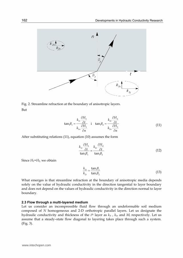
Developments in Hydraulic Conductivity Research
162
Fig 2 Streamline refraction at the boundary of anisotropic layers
But
1 21 2
1 21 2
1 2
tan i tant t
n n
H Hk k
t tH H
k kn n
β βpart partpart part= =part partpart part
(11)
After substituting relations (11) equation (10) assumes the form
1 21 2
1 2tan tan
t t
H Hk k
t tβ βpart partpart part= (12)
Since H1=H2 we obtain
1 1
2 2
tan
tant
t
k
k
ββ= (13)
What emerges is that streamline refraction at the boundary of anisotropic media depends solely on the value of hydraulic conductivity in the direction tangential to layer boundary and does not depend on the values of hydraulic conductivity in the direction normal to layer boundary
23 Flow through a multi-layered medium
Let us consider an incompressible fluid flow through an undeformable soil medium composed of N homogeneous and 2-D orthotropic parallel layers Let us designate the hydraulic conductivity and thickness of the ith layer as kit kin and Mi respectively Let us assume that a steadyndashstate flow diagonal to layering takes place through such a system (Fig 3)
wwwintechopencom
Hydraulic Conductivity of Layered Anisotropic Media
163
Fig 3 Streamlines and filtration direction in a layered medium
Let us also assume that the gradient of hydraulic head along lines A-A and B-B changes according to equations (1) and (2) In such a case streamlines will take the shape of a polygonal chain composed of straight line segments The differences between hydraulic heads along each streamline during the flow through particular layers will have the constant
value ΔHi At layer boundaries according to relation (13) streamline refraction will take place which after adopting the symbols from Fig 3 will be expressed as
( )( )( 1) 1
tan
taniit
i t i
k
k
ββ+ +
= (14)
Water discharge between two streamlines through each layer must be the same For a flow through the ith layer it is
( ) ( )2 2 2 2
2 2 2 2
0
cos cosb
i i i iit in i i it in
H H H Hq k k dt b k k
t n t nβ βpart part part part⎛ ⎞ ⎛ ⎞ ⎛ ⎞ ⎛ ⎞= + = +⎜ ⎟ ⎜ ⎟ ⎜ ⎟ ⎜ ⎟part part part part⎝ ⎠ ⎝ ⎠ ⎝ ⎠ ⎝ ⎠int (15)
Taking into account the relations
( )cosi ii
i
H H
t lϕpart Δ=part (16)
( )sini ii
i
H H
n lϕpart Δ=part (17)
( )cosi
i
i
Ml β= (18)
We obtain the formula
( ) ( ) ( )2 2 2 2cos cos sinii it i in i
i
Hq b k k
lβ ϕ ϕΔ= + (19)
wwwintechopencom
Developments in Hydraulic Conductivity Research
164
For the symbols used in Fig 3 the relation corresponding to equation (13) between βi and ϕi
assumes the form
( ) ( )1tan
tanit
i
in i
k
kϕ β= (20)
On can also prove that
( ) ( )1
1
tan taniti
t
k
kβ β= (21)
Also considering the relations
( ) ( )2
2
11 tan
cosi
i
β β+ = (22)
And
( ) ( ) ( )1
1 1 1
11 1 1
tan
tan tan
n n n
i i t ii i i
n n n
i i i i iti i i
M M k M
a M M k
α β β= = =
= = =
= = =sum sum sumsum sum sum (23)
One can calculate the sum of hydraulic losses along all the flow path through N layers It
comes to
( ) ( ) ( ) ( ) ( )2 2
2 2
1 12 2 2 2
2 221 1
1 1
sin cos sin cossin
N N
it i in iN Ni ii
iN N
i i in
i it i iti i
k M k Mq M
H Hb k
M k M k
α α α αα = == =
= =
⎛ ⎞ ⎛ ⎞⎜ ⎟ ⎜ ⎟⎝ ⎠ ⎝ ⎠Δ = Δ = + +⎛ ⎞ ⎛ ⎞⎜ ⎟ ⎜ ⎟⎝ ⎠ ⎝ ⎠
sum sumsum sum sum sum (24)
In order to determine the hydraulic conductivity of all the layered structure let us replace
the system of layers between the streamlines spaced at b intervals with one homogeneous
layer with the same width b and length l in accordance with Fig 3 If we assume that the
hydraulic conductivity of this layer in the flow direction determined by angle α is ke then
the head loss will be
( )12sin
n
ii
e
q M
Hk b α=Δ = sum
(25)
Comparing the size of hydraulic losses in both cases one obtains the sought formula for the
value of equivalent hydraulic conductivity ke for a flow through a layered medium at any
angle α
wwwintechopencom
Hydraulic Conductivity of Layered Anisotropic Media
165
( ) ( ) ( ) ( )2 2
2 2
2 2 2 21 1
2 21
1 1
1
sin cos sin cos
1
N N
it i in iNi ii
N Ni in
i it i iti i
N
ei
i
k M k MM
kM k M k
kM
α α α α= ==
= =
=
⎛ ⎞ ⎛ ⎞⎜ ⎟ ⎜ ⎟⎝ ⎠ ⎝ ⎠+ +⎛ ⎞ ⎛ ⎞⎜ ⎟ ⎜ ⎟⎝ ⎠ ⎝ ⎠=
sum sumsum sum sumsum
(26)
For a flow parallel to layering (α = 0˚ or α = 180˚) hydraulic conductivity ke will be
designated as kE and according to the above formula it is
1
1
n
it ii
n
ii
k M
k
M
=
=
= sumsumE (27)
while in perpendicular direction (α = 90˚ or α = 270˚) hydraulic conductivity ke will be
designated as kperp and in this case according to formula (26) it is
1
1
n
iin
i
i in
M
kM
k
=perp
=
= sumsum (28)
It is worth emphasizing that equations (27) and (28) can be easily obtained by directly analysing a flow in two directions parallel and perpendicular to layering After substituting relation (27) in equation (26) we obtain
( ) ( ) ( ) ( )2 22 2 2 2
2 21
1
sin cos sin cos1
Ni it in
i in
N
ei
i
M k k
k k k
kM
α α α α=
=
+ +=
sumsum
E E (29)
It follows from equation (29) that in order to determine the equivalent hydraulic
conductivity of a medium composed of anisotropic layers for diagonal direction α it is essential to know all the values of hydraulic conductivity kit and kin of particular layers and their thickness Mi Therefore from the theoretical point of view it is not possible to model a flow through such a structure like that through a single layer On the other hand in the case when particular layers in this structure have isotropic
properties ie one can adopt it in ik k k= = for all the layers relation (29) can be expressed in
the following form (Bear 1972)
( ) ( ) ( ) ( )12 2 2 21
1 1
1 1 1cos sin cos sin
nni
iii i
n n
ei i i
i i
MM
k
k k kM k M
α α α α==perp
= =
= + = +sumsumsum sum E
(30)
wwwintechopencom
Developments in Hydraulic Conductivity Research
166
Then in order to calculate the flow in any direction α it is enough to know the value of hydraulic conductivity for all the layered structure in the direction parallel and perpendicular to the surface constituting layer boundary As expected the form of relation (30) is identical to the function representing hydraulic conductivity in orthotropic soils where two-dimensional anisotropy occurs (Batu 1998 Cheng 2000 Snow 1969 Wieczysty 1982)
( ) ( )2 21 1 1cos sin
e xx yyk k kα α= + (31)
In equation (31) kxx and kyy correspond to the values of hydraulic conductivity in the
principal directions of hydraulic conductivity tensor and xxk k=E while yyk kperp =
If based on equation (30) or (31) one determines the values of ek for various α values then
plotting them in a circle diagram (a graph in polar coordinates) will produce an ellipse It is
referred to as hydraulic conductivity ellipse
24 Angle between hydraulic gradient and filtration velocity
Angle γ between hydraulic gradient (gradH) and filtration velocity v can be determined from the ratio of the dot products of vectors gradH and v to the product of their lengths In the case of a 2D flow and adopting a Cartesian coordinate system whose axes are directed
along the principal axes of hydraulic conductivity tensor angle γ is (Fig 4)
2 22 2
2 2
gradarccos arccos
grad
xx yy
xx yy
H H H Hk k
H x x y y
HH H H H
k kx y x y
γ⎡ ⎤part part part part⎢ ⎥+⎢ ⎥⎛ ⎞ part part part part= = ⎢ ⎥⎜ ⎟⎜ ⎟ ⎢ ⎥⎝ ⎠ ⎛ ⎞ ⎛ ⎞part part part part⎛ ⎞ ⎛ ⎞⎢ ⎥+ +⎜ ⎟ ⎜ ⎟⎜ ⎟ ⎜ ⎟part part part part⎝ ⎠ ⎝ ⎠⎢ ⎥⎝ ⎠ ⎝ ⎠⎣ ⎦
v
v
i (32)
where kxx and kyy denote the values of hydraulic conductivity tensor k
0
0xx
yy
kk
k
⎛ ⎞= ⎜ ⎟⎜ ⎟⎝ ⎠ (33)
Remembering that
( )tanyy
xx
Hk
y
Hk
x
αpartpart= partpart
(34)
one obtains
( ) ( )( ) ( )
( ) ( )( ) ( )
2 2 2 2
2 2 2 2 2 2 2
cos sin cos sinarccos arccos
cos sin cos sin
yy xx
yy xx
k k
k k
α α α λ αγ α α α λ α⎛ ⎞ ⎛ ⎞+ +⎜ ⎟ ⎜ ⎟= =⎜ ⎟ ⎜ ⎟+ +⎝ ⎠⎝ ⎠ (35)
wwwintechopencom
Hydraulic Conductivity of Layered Anisotropic Media
167
Fig 4 Direction differences between hydraulic gradient and filtration velocity
where α denotes the angle between velocity vector and the principal axis of hydraulic conductivity tensor along which value k reaches the maximum values From the above relation one can determine the value of angle α for which angle γ has the
maximum value In order to do this one must determine the derivative d
d
γα and compare it
to zero The angle determined in this way is
1
arctan arctanyy
xx
k
kα λ= plusmn = plusmn (36)
Assuming that kxxgtkyy xx
yy
k
kλ = denotes anisotropy factor For layered media composed of
homogeneous isotropic and parallel layers value kxx corresponds to kE and value kyy ndash to kperp
3 Problems with determining the hydraulic conductivity of anisotropic media
Defining water permeability of anisotropic media requires determining values of hydraulic
conductivity in the direction of principal axes of hydraulic conductivity (Renard 2001
Mozely et al 1996) For media characterized by two-dimensional orthotropy including
layered media these will be two values ndash one in parallel direction and the other ndash
perpendicular to layering In accordance with equation (30) determining hydraulic
conductivity in these directions is possible based on tests of hydraulic conductivity ke for
any two known angles α Then one obtains two equations with two unknowns kE and kperp
When determining these values one can later calculate equivalent hydraulic conductivity ke
in any direction α However if there are any difficulties defining angles α for which water
permeability measurements are performed kE and kperp can be determined by performing a
larger number of measurements for various angles (at least three different angles) and then
matching the obtained results with the ellipse equation (Cheng 2000)
wwwintechopencom
Developments in Hydraulic Conductivity Research
168
This is the theory However determining hydraulic conductivity of layered media in permeameters involves additional problems Analysing relation (35) one can observe that the angle between gradH and v is equal to zero ie both directions coincide only when
angle α is equal to 0 90 180 and 270 degrees then if the flow occurs in the direction parallel or perpendicular to layering When performing measurements along these directions one does not make additional errors resulting from anisotropy However if such a measurement is not possible (eg samples are obtained from hole coring and the hole axis is diagonal to layering) determining the value of hydraulic conductivity in the direction diagonal to layering entails an error It results from the fact that during measurements inside permeameters the appropriate geometric shapes of the sample the proper size and the difference between filtration velocity v and gradH are not maintained Geometric dimensions should allow for maintaining the angle between filtration direction
and the plane through which water flows to the sample and the lateral surfaces of the
sample The inflow and outflow surfaces should be perpendicular to the gradient of
hydraulic head and the lateral surfaces ndash parallel to streamlines composed of straight line
segments (Fig 3)
Meeting the above conditions is very difficult technically moreover it would require prior
knowledge of filtration parameters of particular layers of the medium The knowledge of
these parameters would enable theoretical calculation of hydraulic conductivity without a
need to analyse all the layer structure If we assume however that we do not know these
parameters maintaining appropriate shapes of the sample is not possible In such a case as
an approximation of the abovementioned theoretical solution reflecting a flow diagonal to
layering one can adopt a flow through a medium sample whose geometric dimensions and
flow conditions are consistent with the idea presented in Fig 5 One should remember here
that the cross-section of the sample in the direction perpendicular to filtration direction
should be a rectangle
Fig 5 Diagram of the pattern of adopting a geometric shape for a layered medium sample for permeameter analysis
Unfortunately when performing permeameter tests on samples with the shape presented in
Fig 5 one cannot avoid errors in determination of hydraulic conductivity
wwwintechopencom
Hydraulic Conductivity of Layered Anisotropic Media
169
4 Model calculations
In order to estimate error values connected with determining hydraulic conductivity of
layered media tested in a permeameter water flow through an imaginary soil medium
composed of layers with known properties was calculated The calculations consisted of a
numerical solution of a flow through a specific arrangement of layers in a permeameter and
then defining equivalent hydraulic conductivity The hydraulic conductivity defined in this
way was then compared to theoretically calculated hydraulic conductivity of a layered
structure corresponding to the layer pattern in the permeameter
41 Characteristics of the medium
Model calculations were performed on a soil sample composed of five homogeneous and
isotropic layers with constant thickness (Fig 3) The thickness of particular layers Mi and
hydraulic conductivity ki are presented in Tab 1
Mi ki kE kperp λ Layer No
cm ms-1 ms-1 ms-1 -
1 21 7010-4
2 20 1010-5
3 19 6010-6
4 20 8010-5
5 31 2010-4
20610-4 19810-5 1037
Table 1 Basic properties of a layered medium
For such a layer pattern formula (30) was used to calculate theoretical values of hydraulic
conductivity ke(t) and the angle between vectors gradH and v for different values of angle α
between filtration velocity and the direction of principal axis t Based on the obtained
results hydraulic conductivity ellipse ( ek ) and the values of angles between gradH and
filtration velocity v (angles γ) depending on filtration direction were drawn (Figs 6 and 7) Table 1 also contains calculated hydraulic conductivity values for all the layered structure
in the direction parallel and perpendicular to layer boundaries as well as the anisotropy
factor
42 Numerical solution of permeameter flow
The problem of permeameter flow was solved based on Laplacersquos equation assuming the steady flow of an incompressible fluid through an undeformed medium On the surfaces forming the filtration area boundary boundary conditions were adopted according to Fig 5 while on the boundary of layers with different water permeability Hi = Hi+1 and vni = vni+1 were adopted with Hi Hi+1 denoting the hydraulic heads and vni and vni+1 ndash filtration velocity components normal to the boundary of ith and i+1th layers All the filtration area was divided into 110x14 blocks The calculations were performed with finite difference method in Excel spreadsheet using Gauss-Seidel iteration The calculation results for
different angles α are shown in Tab 2
wwwintechopencom
Developments in Hydraulic Conductivity Research
170
0000
0002
0004
0006
0008
0010
0012
0014
0016
90
8070
60
50
40
30
20
10
0
350
340
330
320
310
300
290280
270
260250
240
230
220
210
200
190
180
170
160
150
140
130
120
110100
k e
k n
k t
t
n
Fig 6 Hydraulic conductivity ellipse
0
10
20
30
40
50
60
90
8070
60
50
40
30
20
10
0
350
340
330
320
310
300
290280
270
260250
240
230
220
210
200
190
180
170
160
150
140
130
120
110100 γ o
t
n
Fig 7 Angle between hydraulic gradient and filtration velocity depending on filtration direction
wwwintechopencom
Hydraulic Conductivity of Layered Anisotropic Media
171
α γ ke(t) ke(num) ( )e t
k
k
Δ
sr
Q
Q
Δ No
˚ ˚ ms-1 ms-1
1 0 000 20610-4 20610-4 000 000
2 45 3949 36110-5 23110-5 3615 -003
3 50 3537 31610-5 21510-5 3201 382
4 55 3114 28210-5 21310-5 2439 304
5 60 2681 25610-5 21110-5 1740 243
6 65 2243 23610-5 20910-5 1145 168
7 70 1799 22210-5 20710-5 664 109
8 75 1352 21110-5 20410-5 318 061
9 80 903 20410-5 20110-5 108 027
10 85 452 20010-5 19910-5 017 006
11 90 000 19810-5 19810-5 009 000
Table 2 Results of numerical calculations of angle γ between hydraulic gradient and filtration velocity and equivalent hydraulic conductivity ke(num)
It contains theoretically and numerically defined values of equivalent hydraulic conductivity (ke(t) and ke(num)) theoretical values of angles γ between gradH and v error in numerical determination of conductivity in relation to the theoretical value
( ) ( )
( ) ( )
100e t e num
e t e t
k kk
k k
minusΔ = as well as error values ( ) 10005
w d
sr w d
Q Q Q
Q Q Q
Δ minus sdot+= resulting from a
numerical comparison of the quantity of water flowing into (Qd) and out of (Qw) the analysed sample This error was regarded as representative for estimating the accuracy of numerical calculation results
43 Error of hydraulic conductivity determination
In order to estimate the error in determining hydraulic conductivity of a layered medium it
was assumed that the analyses had been performed in a permeameter The tests were
carried out on a layered medium presented in Fig 5 for two flow directions in relation to the
principal axis of permeability tensor One direction corresponded to angle α of 45˚ while
the other - 80˚ The values of equivalent hydraulic conductivity determined correctly
through research should be consistent with Tab 2 and amount to 23110-5 ms-1 and 20110-5
ms-1 respectively Using them later to calculate the hydraulic conductivity in the direction
of the principal axis of permeability tensor from formula (30) one obtains kE = 27510-5 ms-1
and kperp = 19910-5 ms-1 The values calculated in this way were compared with the
theoretical properties of a layered medium presented in Tab1 On can see from the
comparison that the values of kperp are only slightly different (the theoretical value is 198 10-5
m s-1) while in the case of kE the difference is very distinct reaching 75 times One should
also emphasize that such a big difference between these results is not caused by the low
accuracy of numerical flow calculations This is proved by a very small difference in the
discharge of water flowing into and out of the sample no more than 03 (Tab 2)
wwwintechopencom
Developments in Hydraulic Conductivity Research
172
The error in hydraulic conductivity determination in a permeameter may be also caused by
the order of layering In order to estimate its value numerical calculations were performed
for the adopted flow through a layered medium composed of the same layers but arranged
in a different order One should emphasize that according to formula (30) the theoretical
value of equivalent hydraulic conductivity kt does not depend on the layering order The
calculation results for a flow at the angle α = 45˚ and for four layering variants are shown in
Tab 3
ke(t) ke(num) ( )e t
k
k
Δ
sr
Q
Q
Δ Variant
No Layering
order ms-1 ms-1
1 5-1-2-3-4-5 23110-5 3615 -0027
2 5-3-2-4-1-5 21610-5 4014 -0058
3 5-1-4-2-3-5 22710-5 3707 0033
4 5-2-4-3-1-5
36110-5
25510-5 2954 0012
Tab 3 Calculation results of hydraulic conductivity of a layered medium for various layering orders
One can see that depending on the considered variant different results are obtained and
anisotropy-related determination error is contained within wide limits In the analysed
examples it oscillates between 30 and over 40 in relation to the theoretical value In order
to illustrate the causes of differences in hydraulic conductivity calculations of streamline
pattern were also performed For the layering in variants 2 and 4 streamline patterns are
shown in Figs 6 and 7
Fig 6 Streamlines in a sample for layering variant 2
wwwintechopencom
Hydraulic Conductivity of Layered Anisotropic Media
173
0
5
10
15
20
25
-20 0 20 40 60 80 100 120 140 160 180
k5k2 k4 k3
k1 k5
Fig 7 Streamlines in a sample for layering variant 4
A distinct difference in streamline patterns is noticeable Certainly the streamline pattern is basically different from the theoretical streamlines shown in Fig 3 which are polygonal chains composed of straight line segments
5 Conclusion
The presented theoretical discussion has demonstrated that flows in layered media composed
of homogeneous and anisotropic layers cannot be modelled as flows in a homogeneous
medium However it is possible in the case of a structure composed of parallel layers
characterised by homogeneity and orthotropy in two dimensions A flow in such a structure
can be modelled as a flow in a single anisotropic layer In such a case one does not have to
know the permeability parameters and the thickness of particular layers In order to calculate
the flow it is then enough to know the hydraulic conductivity in the direction parallel and
perpendicular to layering These values can be determined theoretically by analysing a flow
through such a layered structure in any two directions to the boundary surfaces of the layers
However the calculation results point to a possibility of vital errors occurring while
determining the permeability of layered media in a permeameter This regards those tests
where flow occurs in the direction diagonal to layering The occurrence of major determination
errors is connected with a failure to maintain the appropriate directions of gradH and v and
the proper geometric shape of the sample in a permeameter The value of those errors depends
on the value of anisotropy factor λ and the angular difference between gradH and v In the
performed model calculations of a flow through a layered medium with anisotropy factor
λ = 1037 the obtained value of hydraulic conductivity in the direction perpendicular to layer
boundary was very close to the theoretical one while in the parallel direction it was 75 times
underrated Clearly then such analyses result in very serious underrating of anisotropy factor
The conducted calculations also reveal a considerable influence of layering order on the
determination results of hydraulic conductivity in a permeameter The differences obtained
from model calculations oscillated between c 30 to 40 in relation to the theoretical value
wwwintechopencom
Developments in Hydraulic Conductivity Research
174
To sum up one should clearly state that the correct determination results of hydraulic conductivity of layered media can be obtained by forcing a flow in the direction parallel and perpendicular to layering Any departures from this rule may lead to very large determination errors
6 References
Batu V (1998) Aquifer hydraulics A comprehensive quide to hydrogeologic data analysis John Wiley amp Sons ISBN 0-471-18502-7 New York
Bear J (1972) Dynamics of Fluids in Porous Media Dover Publications ISBN 0-486-65675-6 Cheng A (2000) Multilayered aquifer systems Fundamentals and applications Marcel Dekker
Inc ISBN 0-8247-9875-9 New York Basel Mozely PS amp Davis JM (1996) Relationship between oriented calcite concretions and
permeability correlation structure in alluvial aquifer Sierra Ladrones Formation New Mexiko Journal of Sedimentary Research Vol 66 No 1 (January 1996) pp (11-16) ISSN 1527-1404
Renard Ph Genty A Stauffer F (2001) Laboratory determination of full permeability tensor Journal of Geophysical Research Vol 106 No B11 (November 2001) pp 26443-26452 ISSN 0148-0227
Rogoi M (2007) Dynamika woacuted podziemnych GIG ISBN 978-83-87610-97-5 Katowice Snow D T (1969) Anisotropic permeability of fractured media Water Resour Res 5(6)
1273-1289 ISSN 0043-1397
wwwintechopencom
Developments in Hydraulic Conductivity ResearchEdited by Dr Oagile Dikinya
ISBN 978-953-307-470-2Hard cover 270 pagesPublisher InTechPublished online 28 February 2011Published in print edition February 2011
InTech EuropeUniversity Campus STeP Ri Slavka Krautzeka 83A 51000 Rijeka Croatia Phone +385 (51) 770 447 Fax +385 (51) 686 166wwwintechopencom
InTech ChinaUnit 405 Office Block Hotel Equatorial Shanghai No65 Yan An Road (West) Shanghai 200040 China Phone +86-21-62489820 Fax +86-21-62489821
This book provides the state of the art of the investigation and the in-depth analysis of hydraulic conductivityfrom the theoretical to semi-empirical models perspective as well as policy development associated withmanagement of land resources emanating from drainage-problem soils A group of international expertscontributed to the development of this book It is envisaged that this thought provoking book will excite andappeal to academics engineers researchers and University students who seek to explore the breadth and in-depth knowledge about hydraulic conductivity Investigation into hydraulic conductivity is important to theunderstanding of the movement of solutes and water in the terrestrial environment Transport of these fluidshas various implications on the ecology and quality of environment and subsequently sustenance of livelihoodsof the increasing world population In particular water flow in the vadose zone is of fundamental importance togeoscientists soil scientists hydrogeologists and hydrologists and allied professionals
How to referenceIn order to correctly reference this scholarly work feel free to copy and paste the following
Stanisław Żak (2011) Hydraulic Conductivity of Layered Anisotropic Media Developments in HydraulicConductivity Research Dr Oagile Dikinya (Ed) ISBN 978-953-307-470-2 InTech Available fromhttpwwwintechopencombooksdevelopments-in-hydraulic-conductivity-researchhydraulic-conductivity-of-layered-anisotropic-media
copy 2011 The Author(s) Licensee IntechOpen This chapter is distributedunder the terms of the Creative Commons Attribution-NonCommercial-ShareAlike-30 License which permits use distribution and reproduction fornon-commercial purposes provided the original is properly cited andderivative works building on this content are distributed under the samelicense
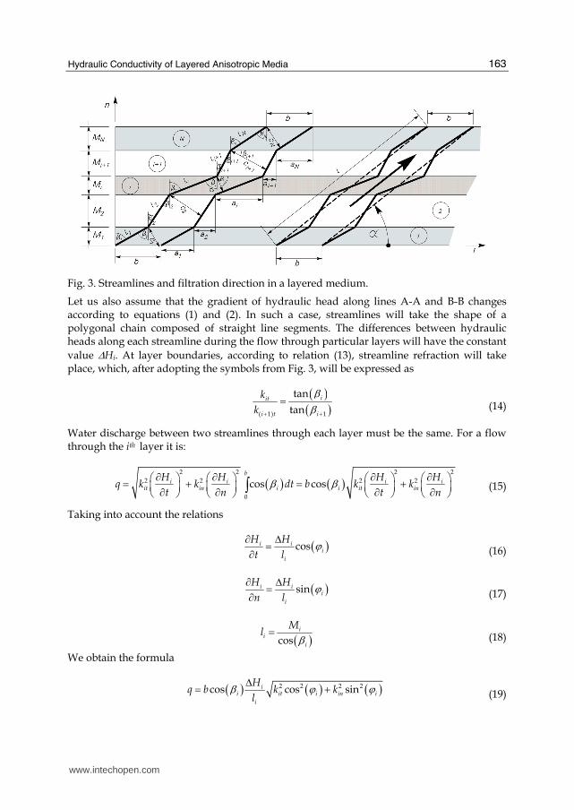
Hydraulic Conductivity of Layered Anisotropic Media
163
Fig 3 Streamlines and filtration direction in a layered medium
Let us also assume that the gradient of hydraulic head along lines A-A and B-B changes according to equations (1) and (2) In such a case streamlines will take the shape of a polygonal chain composed of straight line segments The differences between hydraulic heads along each streamline during the flow through particular layers will have the constant
value ΔHi At layer boundaries according to relation (13) streamline refraction will take place which after adopting the symbols from Fig 3 will be expressed as
( )( )( 1) 1
tan
taniit
i t i
k
k
ββ+ +
= (14)
Water discharge between two streamlines through each layer must be the same For a flow through the ith layer it is
( ) ( )2 2 2 2
2 2 2 2
0
cos cosb
i i i iit in i i it in
H H H Hq k k dt b k k
t n t nβ βpart part part part⎛ ⎞ ⎛ ⎞ ⎛ ⎞ ⎛ ⎞= + = +⎜ ⎟ ⎜ ⎟ ⎜ ⎟ ⎜ ⎟part part part part⎝ ⎠ ⎝ ⎠ ⎝ ⎠ ⎝ ⎠int (15)
Taking into account the relations
( )cosi ii
i
H H
t lϕpart Δ=part (16)
( )sini ii
i
H H
n lϕpart Δ=part (17)
( )cosi
i
i
Ml β= (18)
We obtain the formula
( ) ( ) ( )2 2 2 2cos cos sinii it i in i
i
Hq b k k
lβ ϕ ϕΔ= + (19)
wwwintechopencom
Developments in Hydraulic Conductivity Research
164
For the symbols used in Fig 3 the relation corresponding to equation (13) between βi and ϕi
assumes the form
( ) ( )1tan
tanit
i
in i
k
kϕ β= (20)
On can also prove that
( ) ( )1
1
tan taniti
t
k
kβ β= (21)
Also considering the relations
( ) ( )2
2
11 tan
cosi
i
β β+ = (22)
And
( ) ( ) ( )1
1 1 1
11 1 1
tan
tan tan
n n n
i i t ii i i
n n n
i i i i iti i i
M M k M
a M M k
α β β= = =
= = =
= = =sum sum sumsum sum sum (23)
One can calculate the sum of hydraulic losses along all the flow path through N layers It
comes to
( ) ( ) ( ) ( ) ( )2 2
2 2
1 12 2 2 2
2 221 1
1 1
sin cos sin cossin
N N
it i in iN Ni ii
iN N
i i in
i it i iti i
k M k Mq M
H Hb k
M k M k
α α α αα = == =
= =
⎛ ⎞ ⎛ ⎞⎜ ⎟ ⎜ ⎟⎝ ⎠ ⎝ ⎠Δ = Δ = + +⎛ ⎞ ⎛ ⎞⎜ ⎟ ⎜ ⎟⎝ ⎠ ⎝ ⎠
sum sumsum sum sum sum (24)
In order to determine the hydraulic conductivity of all the layered structure let us replace
the system of layers between the streamlines spaced at b intervals with one homogeneous
layer with the same width b and length l in accordance with Fig 3 If we assume that the
hydraulic conductivity of this layer in the flow direction determined by angle α is ke then
the head loss will be
( )12sin
n
ii
e
q M
Hk b α=Δ = sum
(25)
Comparing the size of hydraulic losses in both cases one obtains the sought formula for the
value of equivalent hydraulic conductivity ke for a flow through a layered medium at any
angle α
wwwintechopencom
Hydraulic Conductivity of Layered Anisotropic Media
165
( ) ( ) ( ) ( )2 2
2 2
2 2 2 21 1
2 21
1 1
1
sin cos sin cos
1
N N
it i in iNi ii
N Ni in
i it i iti i
N
ei
i
k M k MM
kM k M k
kM
α α α α= ==
= =
=
⎛ ⎞ ⎛ ⎞⎜ ⎟ ⎜ ⎟⎝ ⎠ ⎝ ⎠+ +⎛ ⎞ ⎛ ⎞⎜ ⎟ ⎜ ⎟⎝ ⎠ ⎝ ⎠=
sum sumsum sum sumsum
(26)
For a flow parallel to layering (α = 0˚ or α = 180˚) hydraulic conductivity ke will be
designated as kE and according to the above formula it is
1
1
n
it ii
n
ii
k M
k
M
=
=
= sumsumE (27)
while in perpendicular direction (α = 90˚ or α = 270˚) hydraulic conductivity ke will be
designated as kperp and in this case according to formula (26) it is
1
1
n
iin
i
i in
M
kM
k
=perp
=
= sumsum (28)
It is worth emphasizing that equations (27) and (28) can be easily obtained by directly analysing a flow in two directions parallel and perpendicular to layering After substituting relation (27) in equation (26) we obtain
( ) ( ) ( ) ( )2 22 2 2 2
2 21
1
sin cos sin cos1
Ni it in
i in
N
ei
i
M k k
k k k
kM
α α α α=
=
+ +=
sumsum
E E (29)
It follows from equation (29) that in order to determine the equivalent hydraulic
conductivity of a medium composed of anisotropic layers for diagonal direction α it is essential to know all the values of hydraulic conductivity kit and kin of particular layers and their thickness Mi Therefore from the theoretical point of view it is not possible to model a flow through such a structure like that through a single layer On the other hand in the case when particular layers in this structure have isotropic
properties ie one can adopt it in ik k k= = for all the layers relation (29) can be expressed in
the following form (Bear 1972)
( ) ( ) ( ) ( )12 2 2 21
1 1
1 1 1cos sin cos sin
nni
iii i
n n
ei i i
i i
MM
k
k k kM k M
α α α α==perp
= =
= + = +sumsumsum sum E
(30)
wwwintechopencom
Developments in Hydraulic Conductivity Research
166
Then in order to calculate the flow in any direction α it is enough to know the value of hydraulic conductivity for all the layered structure in the direction parallel and perpendicular to the surface constituting layer boundary As expected the form of relation (30) is identical to the function representing hydraulic conductivity in orthotropic soils where two-dimensional anisotropy occurs (Batu 1998 Cheng 2000 Snow 1969 Wieczysty 1982)
( ) ( )2 21 1 1cos sin
e xx yyk k kα α= + (31)
In equation (31) kxx and kyy correspond to the values of hydraulic conductivity in the
principal directions of hydraulic conductivity tensor and xxk k=E while yyk kperp =
If based on equation (30) or (31) one determines the values of ek for various α values then
plotting them in a circle diagram (a graph in polar coordinates) will produce an ellipse It is
referred to as hydraulic conductivity ellipse
24 Angle between hydraulic gradient and filtration velocity
Angle γ between hydraulic gradient (gradH) and filtration velocity v can be determined from the ratio of the dot products of vectors gradH and v to the product of their lengths In the case of a 2D flow and adopting a Cartesian coordinate system whose axes are directed
along the principal axes of hydraulic conductivity tensor angle γ is (Fig 4)
2 22 2
2 2
gradarccos arccos
grad
xx yy
xx yy
H H H Hk k
H x x y y
HH H H H
k kx y x y
γ⎡ ⎤part part part part⎢ ⎥+⎢ ⎥⎛ ⎞ part part part part= = ⎢ ⎥⎜ ⎟⎜ ⎟ ⎢ ⎥⎝ ⎠ ⎛ ⎞ ⎛ ⎞part part part part⎛ ⎞ ⎛ ⎞⎢ ⎥+ +⎜ ⎟ ⎜ ⎟⎜ ⎟ ⎜ ⎟part part part part⎝ ⎠ ⎝ ⎠⎢ ⎥⎝ ⎠ ⎝ ⎠⎣ ⎦
v
v
i (32)
where kxx and kyy denote the values of hydraulic conductivity tensor k
0
0xx
yy
kk
k
⎛ ⎞= ⎜ ⎟⎜ ⎟⎝ ⎠ (33)
Remembering that
( )tanyy
xx
Hk
y
Hk
x
αpartpart= partpart
(34)
one obtains
( ) ( )( ) ( )
( ) ( )( ) ( )
2 2 2 2
2 2 2 2 2 2 2
cos sin cos sinarccos arccos
cos sin cos sin
yy xx
yy xx
k k
k k
α α α λ αγ α α α λ α⎛ ⎞ ⎛ ⎞+ +⎜ ⎟ ⎜ ⎟= =⎜ ⎟ ⎜ ⎟+ +⎝ ⎠⎝ ⎠ (35)
wwwintechopencom
Hydraulic Conductivity of Layered Anisotropic Media
167
Fig 4 Direction differences between hydraulic gradient and filtration velocity
where α denotes the angle between velocity vector and the principal axis of hydraulic conductivity tensor along which value k reaches the maximum values From the above relation one can determine the value of angle α for which angle γ has the
maximum value In order to do this one must determine the derivative d
d
γα and compare it
to zero The angle determined in this way is
1
arctan arctanyy
xx
k
kα λ= plusmn = plusmn (36)
Assuming that kxxgtkyy xx
yy
k
kλ = denotes anisotropy factor For layered media composed of
homogeneous isotropic and parallel layers value kxx corresponds to kE and value kyy ndash to kperp
3 Problems with determining the hydraulic conductivity of anisotropic media
Defining water permeability of anisotropic media requires determining values of hydraulic
conductivity in the direction of principal axes of hydraulic conductivity (Renard 2001
Mozely et al 1996) For media characterized by two-dimensional orthotropy including
layered media these will be two values ndash one in parallel direction and the other ndash
perpendicular to layering In accordance with equation (30) determining hydraulic
conductivity in these directions is possible based on tests of hydraulic conductivity ke for
any two known angles α Then one obtains two equations with two unknowns kE and kperp
When determining these values one can later calculate equivalent hydraulic conductivity ke
in any direction α However if there are any difficulties defining angles α for which water
permeability measurements are performed kE and kperp can be determined by performing a
larger number of measurements for various angles (at least three different angles) and then
matching the obtained results with the ellipse equation (Cheng 2000)
wwwintechopencom
Developments in Hydraulic Conductivity Research
168
This is the theory However determining hydraulic conductivity of layered media in permeameters involves additional problems Analysing relation (35) one can observe that the angle between gradH and v is equal to zero ie both directions coincide only when
angle α is equal to 0 90 180 and 270 degrees then if the flow occurs in the direction parallel or perpendicular to layering When performing measurements along these directions one does not make additional errors resulting from anisotropy However if such a measurement is not possible (eg samples are obtained from hole coring and the hole axis is diagonal to layering) determining the value of hydraulic conductivity in the direction diagonal to layering entails an error It results from the fact that during measurements inside permeameters the appropriate geometric shapes of the sample the proper size and the difference between filtration velocity v and gradH are not maintained Geometric dimensions should allow for maintaining the angle between filtration direction
and the plane through which water flows to the sample and the lateral surfaces of the
sample The inflow and outflow surfaces should be perpendicular to the gradient of
hydraulic head and the lateral surfaces ndash parallel to streamlines composed of straight line
segments (Fig 3)
Meeting the above conditions is very difficult technically moreover it would require prior
knowledge of filtration parameters of particular layers of the medium The knowledge of
these parameters would enable theoretical calculation of hydraulic conductivity without a
need to analyse all the layer structure If we assume however that we do not know these
parameters maintaining appropriate shapes of the sample is not possible In such a case as
an approximation of the abovementioned theoretical solution reflecting a flow diagonal to
layering one can adopt a flow through a medium sample whose geometric dimensions and
flow conditions are consistent with the idea presented in Fig 5 One should remember here
that the cross-section of the sample in the direction perpendicular to filtration direction
should be a rectangle
Fig 5 Diagram of the pattern of adopting a geometric shape for a layered medium sample for permeameter analysis
Unfortunately when performing permeameter tests on samples with the shape presented in
Fig 5 one cannot avoid errors in determination of hydraulic conductivity
wwwintechopencom
Hydraulic Conductivity of Layered Anisotropic Media
169
4 Model calculations
In order to estimate error values connected with determining hydraulic conductivity of
layered media tested in a permeameter water flow through an imaginary soil medium
composed of layers with known properties was calculated The calculations consisted of a
numerical solution of a flow through a specific arrangement of layers in a permeameter and
then defining equivalent hydraulic conductivity The hydraulic conductivity defined in this
way was then compared to theoretically calculated hydraulic conductivity of a layered
structure corresponding to the layer pattern in the permeameter
41 Characteristics of the medium
Model calculations were performed on a soil sample composed of five homogeneous and
isotropic layers with constant thickness (Fig 3) The thickness of particular layers Mi and
hydraulic conductivity ki are presented in Tab 1
Mi ki kE kperp λ Layer No
cm ms-1 ms-1 ms-1 -
1 21 7010-4
2 20 1010-5
3 19 6010-6
4 20 8010-5
5 31 2010-4
20610-4 19810-5 1037
Table 1 Basic properties of a layered medium
For such a layer pattern formula (30) was used to calculate theoretical values of hydraulic
conductivity ke(t) and the angle between vectors gradH and v for different values of angle α
between filtration velocity and the direction of principal axis t Based on the obtained
results hydraulic conductivity ellipse ( ek ) and the values of angles between gradH and
filtration velocity v (angles γ) depending on filtration direction were drawn (Figs 6 and 7) Table 1 also contains calculated hydraulic conductivity values for all the layered structure
in the direction parallel and perpendicular to layer boundaries as well as the anisotropy
factor
42 Numerical solution of permeameter flow
The problem of permeameter flow was solved based on Laplacersquos equation assuming the steady flow of an incompressible fluid through an undeformed medium On the surfaces forming the filtration area boundary boundary conditions were adopted according to Fig 5 while on the boundary of layers with different water permeability Hi = Hi+1 and vni = vni+1 were adopted with Hi Hi+1 denoting the hydraulic heads and vni and vni+1 ndash filtration velocity components normal to the boundary of ith and i+1th layers All the filtration area was divided into 110x14 blocks The calculations were performed with finite difference method in Excel spreadsheet using Gauss-Seidel iteration The calculation results for
different angles α are shown in Tab 2
wwwintechopencom
Developments in Hydraulic Conductivity Research
170
0000
0002
0004
0006
0008
0010
0012
0014
0016
90
8070
60
50
40
30
20
10
0
350
340
330
320
310
300
290280
270
260250
240
230
220
210
200
190
180
170
160
150
140
130
120
110100
k e
k n
k t
t
n
Fig 6 Hydraulic conductivity ellipse
0
10
20
30
40
50
60
90
8070
60
50
40
30
20
10
0
350
340
330
320
310
300
290280
270
260250
240
230
220
210
200
190
180
170
160
150
140
130
120
110100 γ o
t
n
Fig 7 Angle between hydraulic gradient and filtration velocity depending on filtration direction
wwwintechopencom
Hydraulic Conductivity of Layered Anisotropic Media
171
α γ ke(t) ke(num) ( )e t
k
k
Δ
sr
Q
Q
Δ No
˚ ˚ ms-1 ms-1
1 0 000 20610-4 20610-4 000 000
2 45 3949 36110-5 23110-5 3615 -003
3 50 3537 31610-5 21510-5 3201 382
4 55 3114 28210-5 21310-5 2439 304
5 60 2681 25610-5 21110-5 1740 243
6 65 2243 23610-5 20910-5 1145 168
7 70 1799 22210-5 20710-5 664 109
8 75 1352 21110-5 20410-5 318 061
9 80 903 20410-5 20110-5 108 027
10 85 452 20010-5 19910-5 017 006
11 90 000 19810-5 19810-5 009 000
Table 2 Results of numerical calculations of angle γ between hydraulic gradient and filtration velocity and equivalent hydraulic conductivity ke(num)
It contains theoretically and numerically defined values of equivalent hydraulic conductivity (ke(t) and ke(num)) theoretical values of angles γ between gradH and v error in numerical determination of conductivity in relation to the theoretical value
( ) ( )
( ) ( )
100e t e num
e t e t
k kk
k k
minusΔ = as well as error values ( ) 10005
w d
sr w d
Q Q Q
Q Q Q
Δ minus sdot+= resulting from a
numerical comparison of the quantity of water flowing into (Qd) and out of (Qw) the analysed sample This error was regarded as representative for estimating the accuracy of numerical calculation results
43 Error of hydraulic conductivity determination
In order to estimate the error in determining hydraulic conductivity of a layered medium it
was assumed that the analyses had been performed in a permeameter The tests were
carried out on a layered medium presented in Fig 5 for two flow directions in relation to the
principal axis of permeability tensor One direction corresponded to angle α of 45˚ while
the other - 80˚ The values of equivalent hydraulic conductivity determined correctly
through research should be consistent with Tab 2 and amount to 23110-5 ms-1 and 20110-5
ms-1 respectively Using them later to calculate the hydraulic conductivity in the direction
of the principal axis of permeability tensor from formula (30) one obtains kE = 27510-5 ms-1
and kperp = 19910-5 ms-1 The values calculated in this way were compared with the
theoretical properties of a layered medium presented in Tab1 On can see from the
comparison that the values of kperp are only slightly different (the theoretical value is 198 10-5
m s-1) while in the case of kE the difference is very distinct reaching 75 times One should
also emphasize that such a big difference between these results is not caused by the low
accuracy of numerical flow calculations This is proved by a very small difference in the
discharge of water flowing into and out of the sample no more than 03 (Tab 2)
wwwintechopencom
Developments in Hydraulic Conductivity Research
172
The error in hydraulic conductivity determination in a permeameter may be also caused by
the order of layering In order to estimate its value numerical calculations were performed
for the adopted flow through a layered medium composed of the same layers but arranged
in a different order One should emphasize that according to formula (30) the theoretical
value of equivalent hydraulic conductivity kt does not depend on the layering order The
calculation results for a flow at the angle α = 45˚ and for four layering variants are shown in
Tab 3
ke(t) ke(num) ( )e t
k
k
Δ
sr
Q
Q
Δ Variant
No Layering
order ms-1 ms-1
1 5-1-2-3-4-5 23110-5 3615 -0027
2 5-3-2-4-1-5 21610-5 4014 -0058
3 5-1-4-2-3-5 22710-5 3707 0033
4 5-2-4-3-1-5
36110-5
25510-5 2954 0012
Tab 3 Calculation results of hydraulic conductivity of a layered medium for various layering orders
One can see that depending on the considered variant different results are obtained and
anisotropy-related determination error is contained within wide limits In the analysed
examples it oscillates between 30 and over 40 in relation to the theoretical value In order
to illustrate the causes of differences in hydraulic conductivity calculations of streamline
pattern were also performed For the layering in variants 2 and 4 streamline patterns are
shown in Figs 6 and 7
Fig 6 Streamlines in a sample for layering variant 2
wwwintechopencom
Hydraulic Conductivity of Layered Anisotropic Media
173
0
5
10
15
20
25
-20 0 20 40 60 80 100 120 140 160 180
k5k2 k4 k3
k1 k5
Fig 7 Streamlines in a sample for layering variant 4
A distinct difference in streamline patterns is noticeable Certainly the streamline pattern is basically different from the theoretical streamlines shown in Fig 3 which are polygonal chains composed of straight line segments
5 Conclusion
The presented theoretical discussion has demonstrated that flows in layered media composed
of homogeneous and anisotropic layers cannot be modelled as flows in a homogeneous
medium However it is possible in the case of a structure composed of parallel layers
characterised by homogeneity and orthotropy in two dimensions A flow in such a structure
can be modelled as a flow in a single anisotropic layer In such a case one does not have to
know the permeability parameters and the thickness of particular layers In order to calculate
the flow it is then enough to know the hydraulic conductivity in the direction parallel and
perpendicular to layering These values can be determined theoretically by analysing a flow
through such a layered structure in any two directions to the boundary surfaces of the layers
However the calculation results point to a possibility of vital errors occurring while
determining the permeability of layered media in a permeameter This regards those tests
where flow occurs in the direction diagonal to layering The occurrence of major determination
errors is connected with a failure to maintain the appropriate directions of gradH and v and
the proper geometric shape of the sample in a permeameter The value of those errors depends
on the value of anisotropy factor λ and the angular difference between gradH and v In the
performed model calculations of a flow through a layered medium with anisotropy factor
λ = 1037 the obtained value of hydraulic conductivity in the direction perpendicular to layer
boundary was very close to the theoretical one while in the parallel direction it was 75 times
underrated Clearly then such analyses result in very serious underrating of anisotropy factor
The conducted calculations also reveal a considerable influence of layering order on the
determination results of hydraulic conductivity in a permeameter The differences obtained
from model calculations oscillated between c 30 to 40 in relation to the theoretical value
wwwintechopencom
Developments in Hydraulic Conductivity Research
174
To sum up one should clearly state that the correct determination results of hydraulic conductivity of layered media can be obtained by forcing a flow in the direction parallel and perpendicular to layering Any departures from this rule may lead to very large determination errors
6 References
Batu V (1998) Aquifer hydraulics A comprehensive quide to hydrogeologic data analysis John Wiley amp Sons ISBN 0-471-18502-7 New York
Bear J (1972) Dynamics of Fluids in Porous Media Dover Publications ISBN 0-486-65675-6 Cheng A (2000) Multilayered aquifer systems Fundamentals and applications Marcel Dekker
Inc ISBN 0-8247-9875-9 New York Basel Mozely PS amp Davis JM (1996) Relationship between oriented calcite concretions and
permeability correlation structure in alluvial aquifer Sierra Ladrones Formation New Mexiko Journal of Sedimentary Research Vol 66 No 1 (January 1996) pp (11-16) ISSN 1527-1404
Renard Ph Genty A Stauffer F (2001) Laboratory determination of full permeability tensor Journal of Geophysical Research Vol 106 No B11 (November 2001) pp 26443-26452 ISSN 0148-0227
Rogoi M (2007) Dynamika woacuted podziemnych GIG ISBN 978-83-87610-97-5 Katowice Snow D T (1969) Anisotropic permeability of fractured media Water Resour Res 5(6)
1273-1289 ISSN 0043-1397
wwwintechopencom
Developments in Hydraulic Conductivity ResearchEdited by Dr Oagile Dikinya
ISBN 978-953-307-470-2Hard cover 270 pagesPublisher InTechPublished online 28 February 2011Published in print edition February 2011
InTech EuropeUniversity Campus STeP Ri Slavka Krautzeka 83A 51000 Rijeka Croatia Phone +385 (51) 770 447 Fax +385 (51) 686 166wwwintechopencom
InTech ChinaUnit 405 Office Block Hotel Equatorial Shanghai No65 Yan An Road (West) Shanghai 200040 China Phone +86-21-62489820 Fax +86-21-62489821
This book provides the state of the art of the investigation and the in-depth analysis of hydraulic conductivityfrom the theoretical to semi-empirical models perspective as well as policy development associated withmanagement of land resources emanating from drainage-problem soils A group of international expertscontributed to the development of this book It is envisaged that this thought provoking book will excite andappeal to academics engineers researchers and University students who seek to explore the breadth and in-depth knowledge about hydraulic conductivity Investigation into hydraulic conductivity is important to theunderstanding of the movement of solutes and water in the terrestrial environment Transport of these fluidshas various implications on the ecology and quality of environment and subsequently sustenance of livelihoodsof the increasing world population In particular water flow in the vadose zone is of fundamental importance togeoscientists soil scientists hydrogeologists and hydrologists and allied professionals
How to referenceIn order to correctly reference this scholarly work feel free to copy and paste the following
Stanisław Żak (2011) Hydraulic Conductivity of Layered Anisotropic Media Developments in HydraulicConductivity Research Dr Oagile Dikinya (Ed) ISBN 978-953-307-470-2 InTech Available fromhttpwwwintechopencombooksdevelopments-in-hydraulic-conductivity-researchhydraulic-conductivity-of-layered-anisotropic-media
copy 2011 The Author(s) Licensee IntechOpen This chapter is distributedunder the terms of the Creative Commons Attribution-NonCommercial-ShareAlike-30 License which permits use distribution and reproduction fornon-commercial purposes provided the original is properly cited andderivative works building on this content are distributed under the samelicense

Developments in Hydraulic Conductivity Research
164
For the symbols used in Fig 3 the relation corresponding to equation (13) between βi and ϕi
assumes the form
( ) ( )1tan
tanit
i
in i
k
kϕ β= (20)
On can also prove that
( ) ( )1
1
tan taniti
t
k
kβ β= (21)
Also considering the relations
( ) ( )2
2
11 tan
cosi
i
β β+ = (22)
And
( ) ( ) ( )1
1 1 1
11 1 1
tan
tan tan
n n n
i i t ii i i
n n n
i i i i iti i i
M M k M
a M M k
α β β= = =
= = =
= = =sum sum sumsum sum sum (23)
One can calculate the sum of hydraulic losses along all the flow path through N layers It
comes to
( ) ( ) ( ) ( ) ( )2 2
2 2
1 12 2 2 2
2 221 1
1 1
sin cos sin cossin
N N
it i in iN Ni ii
iN N
i i in
i it i iti i
k M k Mq M
H Hb k
M k M k
α α α αα = == =
= =
⎛ ⎞ ⎛ ⎞⎜ ⎟ ⎜ ⎟⎝ ⎠ ⎝ ⎠Δ = Δ = + +⎛ ⎞ ⎛ ⎞⎜ ⎟ ⎜ ⎟⎝ ⎠ ⎝ ⎠
sum sumsum sum sum sum (24)
In order to determine the hydraulic conductivity of all the layered structure let us replace
the system of layers between the streamlines spaced at b intervals with one homogeneous
layer with the same width b and length l in accordance with Fig 3 If we assume that the
hydraulic conductivity of this layer in the flow direction determined by angle α is ke then
the head loss will be
( )12sin
n
ii
e
q M
Hk b α=Δ = sum
(25)
Comparing the size of hydraulic losses in both cases one obtains the sought formula for the
value of equivalent hydraulic conductivity ke for a flow through a layered medium at any
angle α
wwwintechopencom
Hydraulic Conductivity of Layered Anisotropic Media
165
( ) ( ) ( ) ( )2 2
2 2
2 2 2 21 1
2 21
1 1
1
sin cos sin cos
1
N N
it i in iNi ii
N Ni in
i it i iti i
N
ei
i
k M k MM
kM k M k
kM
α α α α= ==
= =
=
⎛ ⎞ ⎛ ⎞⎜ ⎟ ⎜ ⎟⎝ ⎠ ⎝ ⎠+ +⎛ ⎞ ⎛ ⎞⎜ ⎟ ⎜ ⎟⎝ ⎠ ⎝ ⎠=
sum sumsum sum sumsum
(26)
For a flow parallel to layering (α = 0˚ or α = 180˚) hydraulic conductivity ke will be
designated as kE and according to the above formula it is
1
1
n
it ii
n
ii
k M
k
M
=
=
= sumsumE (27)
while in perpendicular direction (α = 90˚ or α = 270˚) hydraulic conductivity ke will be
designated as kperp and in this case according to formula (26) it is
1
1
n
iin
i
i in
M
kM
k
=perp
=
= sumsum (28)
It is worth emphasizing that equations (27) and (28) can be easily obtained by directly analysing a flow in two directions parallel and perpendicular to layering After substituting relation (27) in equation (26) we obtain
( ) ( ) ( ) ( )2 22 2 2 2
2 21
1
sin cos sin cos1
Ni it in
i in
N
ei
i
M k k
k k k
kM
α α α α=
=
+ +=
sumsum
E E (29)
It follows from equation (29) that in order to determine the equivalent hydraulic
conductivity of a medium composed of anisotropic layers for diagonal direction α it is essential to know all the values of hydraulic conductivity kit and kin of particular layers and their thickness Mi Therefore from the theoretical point of view it is not possible to model a flow through such a structure like that through a single layer On the other hand in the case when particular layers in this structure have isotropic
properties ie one can adopt it in ik k k= = for all the layers relation (29) can be expressed in
the following form (Bear 1972)
( ) ( ) ( ) ( )12 2 2 21
1 1
1 1 1cos sin cos sin
nni
iii i
n n
ei i i
i i
MM
k
k k kM k M
α α α α==perp
= =
= + = +sumsumsum sum E
(30)
wwwintechopencom
Developments in Hydraulic Conductivity Research
166
Then in order to calculate the flow in any direction α it is enough to know the value of hydraulic conductivity for all the layered structure in the direction parallel and perpendicular to the surface constituting layer boundary As expected the form of relation (30) is identical to the function representing hydraulic conductivity in orthotropic soils where two-dimensional anisotropy occurs (Batu 1998 Cheng 2000 Snow 1969 Wieczysty 1982)
( ) ( )2 21 1 1cos sin
e xx yyk k kα α= + (31)
In equation (31) kxx and kyy correspond to the values of hydraulic conductivity in the
principal directions of hydraulic conductivity tensor and xxk k=E while yyk kperp =
If based on equation (30) or (31) one determines the values of ek for various α values then
plotting them in a circle diagram (a graph in polar coordinates) will produce an ellipse It is
referred to as hydraulic conductivity ellipse
24 Angle between hydraulic gradient and filtration velocity
Angle γ between hydraulic gradient (gradH) and filtration velocity v can be determined from the ratio of the dot products of vectors gradH and v to the product of their lengths In the case of a 2D flow and adopting a Cartesian coordinate system whose axes are directed
along the principal axes of hydraulic conductivity tensor angle γ is (Fig 4)
2 22 2
2 2
gradarccos arccos
grad
xx yy
xx yy
H H H Hk k
H x x y y
HH H H H
k kx y x y
γ⎡ ⎤part part part part⎢ ⎥+⎢ ⎥⎛ ⎞ part part part part= = ⎢ ⎥⎜ ⎟⎜ ⎟ ⎢ ⎥⎝ ⎠ ⎛ ⎞ ⎛ ⎞part part part part⎛ ⎞ ⎛ ⎞⎢ ⎥+ +⎜ ⎟ ⎜ ⎟⎜ ⎟ ⎜ ⎟part part part part⎝ ⎠ ⎝ ⎠⎢ ⎥⎝ ⎠ ⎝ ⎠⎣ ⎦
v
v
i (32)
where kxx and kyy denote the values of hydraulic conductivity tensor k
0
0xx
yy
kk
k
⎛ ⎞= ⎜ ⎟⎜ ⎟⎝ ⎠ (33)
Remembering that
( )tanyy
xx
Hk
y
Hk
x
αpartpart= partpart
(34)
one obtains
( ) ( )( ) ( )
( ) ( )( ) ( )
2 2 2 2
2 2 2 2 2 2 2
cos sin cos sinarccos arccos
cos sin cos sin
yy xx
yy xx
k k
k k
α α α λ αγ α α α λ α⎛ ⎞ ⎛ ⎞+ +⎜ ⎟ ⎜ ⎟= =⎜ ⎟ ⎜ ⎟+ +⎝ ⎠⎝ ⎠ (35)
wwwintechopencom
Hydraulic Conductivity of Layered Anisotropic Media
167
Fig 4 Direction differences between hydraulic gradient and filtration velocity
where α denotes the angle between velocity vector and the principal axis of hydraulic conductivity tensor along which value k reaches the maximum values From the above relation one can determine the value of angle α for which angle γ has the
maximum value In order to do this one must determine the derivative d
d
γα and compare it
to zero The angle determined in this way is
1
arctan arctanyy
xx
k
kα λ= plusmn = plusmn (36)
Assuming that kxxgtkyy xx
yy
k
kλ = denotes anisotropy factor For layered media composed of
homogeneous isotropic and parallel layers value kxx corresponds to kE and value kyy ndash to kperp
3 Problems with determining the hydraulic conductivity of anisotropic media
Defining water permeability of anisotropic media requires determining values of hydraulic
conductivity in the direction of principal axes of hydraulic conductivity (Renard 2001
Mozely et al 1996) For media characterized by two-dimensional orthotropy including
layered media these will be two values ndash one in parallel direction and the other ndash
perpendicular to layering In accordance with equation (30) determining hydraulic
conductivity in these directions is possible based on tests of hydraulic conductivity ke for
any two known angles α Then one obtains two equations with two unknowns kE and kperp
When determining these values one can later calculate equivalent hydraulic conductivity ke
in any direction α However if there are any difficulties defining angles α for which water
permeability measurements are performed kE and kperp can be determined by performing a
larger number of measurements for various angles (at least three different angles) and then
matching the obtained results with the ellipse equation (Cheng 2000)
wwwintechopencom
Developments in Hydraulic Conductivity Research
168
This is the theory However determining hydraulic conductivity of layered media in permeameters involves additional problems Analysing relation (35) one can observe that the angle between gradH and v is equal to zero ie both directions coincide only when
angle α is equal to 0 90 180 and 270 degrees then if the flow occurs in the direction parallel or perpendicular to layering When performing measurements along these directions one does not make additional errors resulting from anisotropy However if such a measurement is not possible (eg samples are obtained from hole coring and the hole axis is diagonal to layering) determining the value of hydraulic conductivity in the direction diagonal to layering entails an error It results from the fact that during measurements inside permeameters the appropriate geometric shapes of the sample the proper size and the difference between filtration velocity v and gradH are not maintained Geometric dimensions should allow for maintaining the angle between filtration direction
and the plane through which water flows to the sample and the lateral surfaces of the
sample The inflow and outflow surfaces should be perpendicular to the gradient of
hydraulic head and the lateral surfaces ndash parallel to streamlines composed of straight line
segments (Fig 3)
Meeting the above conditions is very difficult technically moreover it would require prior
knowledge of filtration parameters of particular layers of the medium The knowledge of
these parameters would enable theoretical calculation of hydraulic conductivity without a
need to analyse all the layer structure If we assume however that we do not know these
parameters maintaining appropriate shapes of the sample is not possible In such a case as
an approximation of the abovementioned theoretical solution reflecting a flow diagonal to
layering one can adopt a flow through a medium sample whose geometric dimensions and
flow conditions are consistent with the idea presented in Fig 5 One should remember here
that the cross-section of the sample in the direction perpendicular to filtration direction
should be a rectangle
Fig 5 Diagram of the pattern of adopting a geometric shape for a layered medium sample for permeameter analysis
Unfortunately when performing permeameter tests on samples with the shape presented in
Fig 5 one cannot avoid errors in determination of hydraulic conductivity
wwwintechopencom
Hydraulic Conductivity of Layered Anisotropic Media
169
4 Model calculations
In order to estimate error values connected with determining hydraulic conductivity of
layered media tested in a permeameter water flow through an imaginary soil medium
composed of layers with known properties was calculated The calculations consisted of a
numerical solution of a flow through a specific arrangement of layers in a permeameter and
then defining equivalent hydraulic conductivity The hydraulic conductivity defined in this
way was then compared to theoretically calculated hydraulic conductivity of a layered
structure corresponding to the layer pattern in the permeameter
41 Characteristics of the medium
Model calculations were performed on a soil sample composed of five homogeneous and
isotropic layers with constant thickness (Fig 3) The thickness of particular layers Mi and
hydraulic conductivity ki are presented in Tab 1
Mi ki kE kperp λ Layer No
cm ms-1 ms-1 ms-1 -
1 21 7010-4
2 20 1010-5
3 19 6010-6
4 20 8010-5
5 31 2010-4
20610-4 19810-5 1037
Table 1 Basic properties of a layered medium
For such a layer pattern formula (30) was used to calculate theoretical values of hydraulic
conductivity ke(t) and the angle between vectors gradH and v for different values of angle α
between filtration velocity and the direction of principal axis t Based on the obtained
results hydraulic conductivity ellipse ( ek ) and the values of angles between gradH and
filtration velocity v (angles γ) depending on filtration direction were drawn (Figs 6 and 7) Table 1 also contains calculated hydraulic conductivity values for all the layered structure
in the direction parallel and perpendicular to layer boundaries as well as the anisotropy
factor
42 Numerical solution of permeameter flow
The problem of permeameter flow was solved based on Laplacersquos equation assuming the steady flow of an incompressible fluid through an undeformed medium On the surfaces forming the filtration area boundary boundary conditions were adopted according to Fig 5 while on the boundary of layers with different water permeability Hi = Hi+1 and vni = vni+1 were adopted with Hi Hi+1 denoting the hydraulic heads and vni and vni+1 ndash filtration velocity components normal to the boundary of ith and i+1th layers All the filtration area was divided into 110x14 blocks The calculations were performed with finite difference method in Excel spreadsheet using Gauss-Seidel iteration The calculation results for
different angles α are shown in Tab 2
wwwintechopencom
Developments in Hydraulic Conductivity Research
170
0000
0002
0004
0006
0008
0010
0012
0014
0016
90
8070
60
50
40
30
20
10
0
350
340
330
320
310
300
290280
270
260250
240
230
220
210
200
190
180
170
160
150
140
130
120
110100
k e
k n
k t
t
n
Fig 6 Hydraulic conductivity ellipse
0
10
20
30
40
50
60
90
8070
60
50
40
30
20
10
0
350
340
330
320
310
300
290280
270
260250
240
230
220
210
200
190
180
170
160
150
140
130
120
110100 γ o
t
n
Fig 7 Angle between hydraulic gradient and filtration velocity depending on filtration direction
wwwintechopencom
Hydraulic Conductivity of Layered Anisotropic Media
171
α γ ke(t) ke(num) ( )e t
k
k
Δ
sr
Q
Q
Δ No
˚ ˚ ms-1 ms-1
1 0 000 20610-4 20610-4 000 000
2 45 3949 36110-5 23110-5 3615 -003
3 50 3537 31610-5 21510-5 3201 382
4 55 3114 28210-5 21310-5 2439 304
5 60 2681 25610-5 21110-5 1740 243
6 65 2243 23610-5 20910-5 1145 168
7 70 1799 22210-5 20710-5 664 109
8 75 1352 21110-5 20410-5 318 061
9 80 903 20410-5 20110-5 108 027
10 85 452 20010-5 19910-5 017 006
11 90 000 19810-5 19810-5 009 000
Table 2 Results of numerical calculations of angle γ between hydraulic gradient and filtration velocity and equivalent hydraulic conductivity ke(num)
It contains theoretically and numerically defined values of equivalent hydraulic conductivity (ke(t) and ke(num)) theoretical values of angles γ between gradH and v error in numerical determination of conductivity in relation to the theoretical value
( ) ( )
( ) ( )
100e t e num
e t e t
k kk
k k
minusΔ = as well as error values ( ) 10005
w d
sr w d
Q Q Q
Q Q Q
Δ minus sdot+= resulting from a
numerical comparison of the quantity of water flowing into (Qd) and out of (Qw) the analysed sample This error was regarded as representative for estimating the accuracy of numerical calculation results
43 Error of hydraulic conductivity determination
In order to estimate the error in determining hydraulic conductivity of a layered medium it
was assumed that the analyses had been performed in a permeameter The tests were
carried out on a layered medium presented in Fig 5 for two flow directions in relation to the
principal axis of permeability tensor One direction corresponded to angle α of 45˚ while
the other - 80˚ The values of equivalent hydraulic conductivity determined correctly
through research should be consistent with Tab 2 and amount to 23110-5 ms-1 and 20110-5
ms-1 respectively Using them later to calculate the hydraulic conductivity in the direction
of the principal axis of permeability tensor from formula (30) one obtains kE = 27510-5 ms-1
and kperp = 19910-5 ms-1 The values calculated in this way were compared with the
theoretical properties of a layered medium presented in Tab1 On can see from the
comparison that the values of kperp are only slightly different (the theoretical value is 198 10-5
m s-1) while in the case of kE the difference is very distinct reaching 75 times One should
also emphasize that such a big difference between these results is not caused by the low
accuracy of numerical flow calculations This is proved by a very small difference in the
discharge of water flowing into and out of the sample no more than 03 (Tab 2)
wwwintechopencom
Developments in Hydraulic Conductivity Research
172
The error in hydraulic conductivity determination in a permeameter may be also caused by
the order of layering In order to estimate its value numerical calculations were performed
for the adopted flow through a layered medium composed of the same layers but arranged
in a different order One should emphasize that according to formula (30) the theoretical
value of equivalent hydraulic conductivity kt does not depend on the layering order The
calculation results for a flow at the angle α = 45˚ and for four layering variants are shown in
Tab 3
ke(t) ke(num) ( )e t
k
k
Δ
sr
Q
Q
Δ Variant
No Layering
order ms-1 ms-1
1 5-1-2-3-4-5 23110-5 3615 -0027
2 5-3-2-4-1-5 21610-5 4014 -0058
3 5-1-4-2-3-5 22710-5 3707 0033
4 5-2-4-3-1-5
36110-5
25510-5 2954 0012
Tab 3 Calculation results of hydraulic conductivity of a layered medium for various layering orders
One can see that depending on the considered variant different results are obtained and
anisotropy-related determination error is contained within wide limits In the analysed
examples it oscillates between 30 and over 40 in relation to the theoretical value In order
to illustrate the causes of differences in hydraulic conductivity calculations of streamline
pattern were also performed For the layering in variants 2 and 4 streamline patterns are
shown in Figs 6 and 7
Fig 6 Streamlines in a sample for layering variant 2
wwwintechopencom
Hydraulic Conductivity of Layered Anisotropic Media
173
0
5
10
15
20
25
-20 0 20 40 60 80 100 120 140 160 180
k5k2 k4 k3
k1 k5
Fig 7 Streamlines in a sample for layering variant 4
A distinct difference in streamline patterns is noticeable Certainly the streamline pattern is basically different from the theoretical streamlines shown in Fig 3 which are polygonal chains composed of straight line segments
5 Conclusion
The presented theoretical discussion has demonstrated that flows in layered media composed
of homogeneous and anisotropic layers cannot be modelled as flows in a homogeneous
medium However it is possible in the case of a structure composed of parallel layers
characterised by homogeneity and orthotropy in two dimensions A flow in such a structure
can be modelled as a flow in a single anisotropic layer In such a case one does not have to
know the permeability parameters and the thickness of particular layers In order to calculate
the flow it is then enough to know the hydraulic conductivity in the direction parallel and
perpendicular to layering These values can be determined theoretically by analysing a flow
through such a layered structure in any two directions to the boundary surfaces of the layers
However the calculation results point to a possibility of vital errors occurring while
determining the permeability of layered media in a permeameter This regards those tests
where flow occurs in the direction diagonal to layering The occurrence of major determination
errors is connected with a failure to maintain the appropriate directions of gradH and v and
the proper geometric shape of the sample in a permeameter The value of those errors depends
on the value of anisotropy factor λ and the angular difference between gradH and v In the
performed model calculations of a flow through a layered medium with anisotropy factor
λ = 1037 the obtained value of hydraulic conductivity in the direction perpendicular to layer
boundary was very close to the theoretical one while in the parallel direction it was 75 times
underrated Clearly then such analyses result in very serious underrating of anisotropy factor
The conducted calculations also reveal a considerable influence of layering order on the
determination results of hydraulic conductivity in a permeameter The differences obtained
from model calculations oscillated between c 30 to 40 in relation to the theoretical value
wwwintechopencom
Developments in Hydraulic Conductivity Research
174
To sum up one should clearly state that the correct determination results of hydraulic conductivity of layered media can be obtained by forcing a flow in the direction parallel and perpendicular to layering Any departures from this rule may lead to very large determination errors
6 References
Batu V (1998) Aquifer hydraulics A comprehensive quide to hydrogeologic data analysis John Wiley amp Sons ISBN 0-471-18502-7 New York
Bear J (1972) Dynamics of Fluids in Porous Media Dover Publications ISBN 0-486-65675-6 Cheng A (2000) Multilayered aquifer systems Fundamentals and applications Marcel Dekker
Inc ISBN 0-8247-9875-9 New York Basel Mozely PS amp Davis JM (1996) Relationship between oriented calcite concretions and
permeability correlation structure in alluvial aquifer Sierra Ladrones Formation New Mexiko Journal of Sedimentary Research Vol 66 No 1 (January 1996) pp (11-16) ISSN 1527-1404
Renard Ph Genty A Stauffer F (2001) Laboratory determination of full permeability tensor Journal of Geophysical Research Vol 106 No B11 (November 2001) pp 26443-26452 ISSN 0148-0227
Rogoi M (2007) Dynamika woacuted podziemnych GIG ISBN 978-83-87610-97-5 Katowice Snow D T (1969) Anisotropic permeability of fractured media Water Resour Res 5(6)
1273-1289 ISSN 0043-1397
wwwintechopencom
Developments in Hydraulic Conductivity ResearchEdited by Dr Oagile Dikinya
ISBN 978-953-307-470-2Hard cover 270 pagesPublisher InTechPublished online 28 February 2011Published in print edition February 2011
InTech EuropeUniversity Campus STeP Ri Slavka Krautzeka 83A 51000 Rijeka Croatia Phone +385 (51) 770 447 Fax +385 (51) 686 166wwwintechopencom
InTech ChinaUnit 405 Office Block Hotel Equatorial Shanghai No65 Yan An Road (West) Shanghai 200040 China Phone +86-21-62489820 Fax +86-21-62489821
This book provides the state of the art of the investigation and the in-depth analysis of hydraulic conductivityfrom the theoretical to semi-empirical models perspective as well as policy development associated withmanagement of land resources emanating from drainage-problem soils A group of international expertscontributed to the development of this book It is envisaged that this thought provoking book will excite andappeal to academics engineers researchers and University students who seek to explore the breadth and in-depth knowledge about hydraulic conductivity Investigation into hydraulic conductivity is important to theunderstanding of the movement of solutes and water in the terrestrial environment Transport of these fluidshas various implications on the ecology and quality of environment and subsequently sustenance of livelihoodsof the increasing world population In particular water flow in the vadose zone is of fundamental importance togeoscientists soil scientists hydrogeologists and hydrologists and allied professionals
How to referenceIn order to correctly reference this scholarly work feel free to copy and paste the following
Stanisław Żak (2011) Hydraulic Conductivity of Layered Anisotropic Media Developments in HydraulicConductivity Research Dr Oagile Dikinya (Ed) ISBN 978-953-307-470-2 InTech Available fromhttpwwwintechopencombooksdevelopments-in-hydraulic-conductivity-researchhydraulic-conductivity-of-layered-anisotropic-media
copy 2011 The Author(s) Licensee IntechOpen This chapter is distributedunder the terms of the Creative Commons Attribution-NonCommercial-ShareAlike-30 License which permits use distribution and reproduction fornon-commercial purposes provided the original is properly cited andderivative works building on this content are distributed under the samelicense

Hydraulic Conductivity of Layered Anisotropic Media
165
( ) ( ) ( ) ( )2 2
2 2
2 2 2 21 1
2 21
1 1
1
sin cos sin cos
1
N N
it i in iNi ii
N Ni in
i it i iti i
N
ei
i
k M k MM
kM k M k
kM
α α α α= ==
= =
=
⎛ ⎞ ⎛ ⎞⎜ ⎟ ⎜ ⎟⎝ ⎠ ⎝ ⎠+ +⎛ ⎞ ⎛ ⎞⎜ ⎟ ⎜ ⎟⎝ ⎠ ⎝ ⎠=
sum sumsum sum sumsum
(26)
For a flow parallel to layering (α = 0˚ or α = 180˚) hydraulic conductivity ke will be
designated as kE and according to the above formula it is
1
1
n
it ii
n
ii
k M
k
M
=
=
= sumsumE (27)
while in perpendicular direction (α = 90˚ or α = 270˚) hydraulic conductivity ke will be
designated as kperp and in this case according to formula (26) it is
1
1
n
iin
i
i in
M
kM
k
=perp
=
= sumsum (28)
It is worth emphasizing that equations (27) and (28) can be easily obtained by directly analysing a flow in two directions parallel and perpendicular to layering After substituting relation (27) in equation (26) we obtain
( ) ( ) ( ) ( )2 22 2 2 2
2 21
1
sin cos sin cos1
Ni it in
i in
N
ei
i
M k k
k k k
kM
α α α α=
=
+ +=
sumsum
E E (29)
It follows from equation (29) that in order to determine the equivalent hydraulic
conductivity of a medium composed of anisotropic layers for diagonal direction α it is essential to know all the values of hydraulic conductivity kit and kin of particular layers and their thickness Mi Therefore from the theoretical point of view it is not possible to model a flow through such a structure like that through a single layer On the other hand in the case when particular layers in this structure have isotropic
properties ie one can adopt it in ik k k= = for all the layers relation (29) can be expressed in
the following form (Bear 1972)
( ) ( ) ( ) ( )12 2 2 21
1 1
1 1 1cos sin cos sin
nni
iii i
n n
ei i i
i i
MM
k
k k kM k M
α α α α==perp
= =
= + = +sumsumsum sum E
(30)
wwwintechopencom
Developments in Hydraulic Conductivity Research
166
Then in order to calculate the flow in any direction α it is enough to know the value of hydraulic conductivity for all the layered structure in the direction parallel and perpendicular to the surface constituting layer boundary As expected the form of relation (30) is identical to the function representing hydraulic conductivity in orthotropic soils where two-dimensional anisotropy occurs (Batu 1998 Cheng 2000 Snow 1969 Wieczysty 1982)
( ) ( )2 21 1 1cos sin
e xx yyk k kα α= + (31)
In equation (31) kxx and kyy correspond to the values of hydraulic conductivity in the
principal directions of hydraulic conductivity tensor and xxk k=E while yyk kperp =
If based on equation (30) or (31) one determines the values of ek for various α values then
plotting them in a circle diagram (a graph in polar coordinates) will produce an ellipse It is
referred to as hydraulic conductivity ellipse
24 Angle between hydraulic gradient and filtration velocity
Angle γ between hydraulic gradient (gradH) and filtration velocity v can be determined from the ratio of the dot products of vectors gradH and v to the product of their lengths In the case of a 2D flow and adopting a Cartesian coordinate system whose axes are directed
along the principal axes of hydraulic conductivity tensor angle γ is (Fig 4)
2 22 2
2 2
gradarccos arccos
grad
xx yy
xx yy
H H H Hk k
H x x y y
HH H H H
k kx y x y
γ⎡ ⎤part part part part⎢ ⎥+⎢ ⎥⎛ ⎞ part part part part= = ⎢ ⎥⎜ ⎟⎜ ⎟ ⎢ ⎥⎝ ⎠ ⎛ ⎞ ⎛ ⎞part part part part⎛ ⎞ ⎛ ⎞⎢ ⎥+ +⎜ ⎟ ⎜ ⎟⎜ ⎟ ⎜ ⎟part part part part⎝ ⎠ ⎝ ⎠⎢ ⎥⎝ ⎠ ⎝ ⎠⎣ ⎦
v
v
i (32)
where kxx and kyy denote the values of hydraulic conductivity tensor k
0
0xx
yy
kk
k
⎛ ⎞= ⎜ ⎟⎜ ⎟⎝ ⎠ (33)
Remembering that
( )tanyy
xx
Hk
y
Hk
x
αpartpart= partpart
(34)
one obtains
( ) ( )( ) ( )
( ) ( )( ) ( )
2 2 2 2
2 2 2 2 2 2 2
cos sin cos sinarccos arccos
cos sin cos sin
yy xx
yy xx
k k
k k
α α α λ αγ α α α λ α⎛ ⎞ ⎛ ⎞+ +⎜ ⎟ ⎜ ⎟= =⎜ ⎟ ⎜ ⎟+ +⎝ ⎠⎝ ⎠ (35)
wwwintechopencom
Hydraulic Conductivity of Layered Anisotropic Media
167
Fig 4 Direction differences between hydraulic gradient and filtration velocity
where α denotes the angle between velocity vector and the principal axis of hydraulic conductivity tensor along which value k reaches the maximum values From the above relation one can determine the value of angle α for which angle γ has the
maximum value In order to do this one must determine the derivative d
d
γα and compare it
to zero The angle determined in this way is
1
arctan arctanyy
xx
k
kα λ= plusmn = plusmn (36)
Assuming that kxxgtkyy xx
yy
k
kλ = denotes anisotropy factor For layered media composed of
homogeneous isotropic and parallel layers value kxx corresponds to kE and value kyy ndash to kperp
3 Problems with determining the hydraulic conductivity of anisotropic media
Defining water permeability of anisotropic media requires determining values of hydraulic
conductivity in the direction of principal axes of hydraulic conductivity (Renard 2001
Mozely et al 1996) For media characterized by two-dimensional orthotropy including
layered media these will be two values ndash one in parallel direction and the other ndash
perpendicular to layering In accordance with equation (30) determining hydraulic
conductivity in these directions is possible based on tests of hydraulic conductivity ke for
any two known angles α Then one obtains two equations with two unknowns kE and kperp
When determining these values one can later calculate equivalent hydraulic conductivity ke
in any direction α However if there are any difficulties defining angles α for which water
permeability measurements are performed kE and kperp can be determined by performing a
larger number of measurements for various angles (at least three different angles) and then
matching the obtained results with the ellipse equation (Cheng 2000)
wwwintechopencom
Developments in Hydraulic Conductivity Research
168
This is the theory However determining hydraulic conductivity of layered media in permeameters involves additional problems Analysing relation (35) one can observe that the angle between gradH and v is equal to zero ie both directions coincide only when
angle α is equal to 0 90 180 and 270 degrees then if the flow occurs in the direction parallel or perpendicular to layering When performing measurements along these directions one does not make additional errors resulting from anisotropy However if such a measurement is not possible (eg samples are obtained from hole coring and the hole axis is diagonal to layering) determining the value of hydraulic conductivity in the direction diagonal to layering entails an error It results from the fact that during measurements inside permeameters the appropriate geometric shapes of the sample the proper size and the difference between filtration velocity v and gradH are not maintained Geometric dimensions should allow for maintaining the angle between filtration direction
and the plane through which water flows to the sample and the lateral surfaces of the
sample The inflow and outflow surfaces should be perpendicular to the gradient of
hydraulic head and the lateral surfaces ndash parallel to streamlines composed of straight line
segments (Fig 3)
Meeting the above conditions is very difficult technically moreover it would require prior
knowledge of filtration parameters of particular layers of the medium The knowledge of
these parameters would enable theoretical calculation of hydraulic conductivity without a
need to analyse all the layer structure If we assume however that we do not know these
parameters maintaining appropriate shapes of the sample is not possible In such a case as
an approximation of the abovementioned theoretical solution reflecting a flow diagonal to
layering one can adopt a flow through a medium sample whose geometric dimensions and
flow conditions are consistent with the idea presented in Fig 5 One should remember here
that the cross-section of the sample in the direction perpendicular to filtration direction
should be a rectangle
Fig 5 Diagram of the pattern of adopting a geometric shape for a layered medium sample for permeameter analysis
Unfortunately when performing permeameter tests on samples with the shape presented in
Fig 5 one cannot avoid errors in determination of hydraulic conductivity
wwwintechopencom
Hydraulic Conductivity of Layered Anisotropic Media
169
4 Model calculations
In order to estimate error values connected with determining hydraulic conductivity of
layered media tested in a permeameter water flow through an imaginary soil medium
composed of layers with known properties was calculated The calculations consisted of a
numerical solution of a flow through a specific arrangement of layers in a permeameter and
then defining equivalent hydraulic conductivity The hydraulic conductivity defined in this
way was then compared to theoretically calculated hydraulic conductivity of a layered
structure corresponding to the layer pattern in the permeameter
41 Characteristics of the medium
Model calculations were performed on a soil sample composed of five homogeneous and
isotropic layers with constant thickness (Fig 3) The thickness of particular layers Mi and
hydraulic conductivity ki are presented in Tab 1
Mi ki kE kperp λ Layer No
cm ms-1 ms-1 ms-1 -
1 21 7010-4
2 20 1010-5
3 19 6010-6
4 20 8010-5
5 31 2010-4
20610-4 19810-5 1037
Table 1 Basic properties of a layered medium
For such a layer pattern formula (30) was used to calculate theoretical values of hydraulic
conductivity ke(t) and the angle between vectors gradH and v for different values of angle α
between filtration velocity and the direction of principal axis t Based on the obtained
results hydraulic conductivity ellipse ( ek ) and the values of angles between gradH and
filtration velocity v (angles γ) depending on filtration direction were drawn (Figs 6 and 7) Table 1 also contains calculated hydraulic conductivity values for all the layered structure
in the direction parallel and perpendicular to layer boundaries as well as the anisotropy
factor
42 Numerical solution of permeameter flow
The problem of permeameter flow was solved based on Laplacersquos equation assuming the steady flow of an incompressible fluid through an undeformed medium On the surfaces forming the filtration area boundary boundary conditions were adopted according to Fig 5 while on the boundary of layers with different water permeability Hi = Hi+1 and vni = vni+1 were adopted with Hi Hi+1 denoting the hydraulic heads and vni and vni+1 ndash filtration velocity components normal to the boundary of ith and i+1th layers All the filtration area was divided into 110x14 blocks The calculations were performed with finite difference method in Excel spreadsheet using Gauss-Seidel iteration The calculation results for
different angles α are shown in Tab 2
wwwintechopencom
Developments in Hydraulic Conductivity Research
170
0000
0002
0004
0006
0008
0010
0012
0014
0016
90
8070
60
50
40
30
20
10
0
350
340
330
320
310
300
290280
270
260250
240
230
220
210
200
190
180
170
160
150
140
130
120
110100
k e
k n
k t
t
n
Fig 6 Hydraulic conductivity ellipse
0
10
20
30
40
50
60
90
8070
60
50
40
30
20
10
0
350
340
330
320
310
300
290280
270
260250
240
230
220
210
200
190
180
170
160
150
140
130
120
110100 γ o
t
n
Fig 7 Angle between hydraulic gradient and filtration velocity depending on filtration direction
wwwintechopencom
Hydraulic Conductivity of Layered Anisotropic Media
171
α γ ke(t) ke(num) ( )e t
k
k
Δ
sr
Q
Q
Δ No
˚ ˚ ms-1 ms-1
1 0 000 20610-4 20610-4 000 000
2 45 3949 36110-5 23110-5 3615 -003
3 50 3537 31610-5 21510-5 3201 382
4 55 3114 28210-5 21310-5 2439 304
5 60 2681 25610-5 21110-5 1740 243
6 65 2243 23610-5 20910-5 1145 168
7 70 1799 22210-5 20710-5 664 109
8 75 1352 21110-5 20410-5 318 061
9 80 903 20410-5 20110-5 108 027
10 85 452 20010-5 19910-5 017 006
11 90 000 19810-5 19810-5 009 000
Table 2 Results of numerical calculations of angle γ between hydraulic gradient and filtration velocity and equivalent hydraulic conductivity ke(num)
It contains theoretically and numerically defined values of equivalent hydraulic conductivity (ke(t) and ke(num)) theoretical values of angles γ between gradH and v error in numerical determination of conductivity in relation to the theoretical value
( ) ( )
( ) ( )
100e t e num
e t e t
k kk
k k
minusΔ = as well as error values ( ) 10005
w d
sr w d
Q Q Q
Q Q Q
Δ minus sdot+= resulting from a
numerical comparison of the quantity of water flowing into (Qd) and out of (Qw) the analysed sample This error was regarded as representative for estimating the accuracy of numerical calculation results
43 Error of hydraulic conductivity determination
In order to estimate the error in determining hydraulic conductivity of a layered medium it
was assumed that the analyses had been performed in a permeameter The tests were
carried out on a layered medium presented in Fig 5 for two flow directions in relation to the
principal axis of permeability tensor One direction corresponded to angle α of 45˚ while
the other - 80˚ The values of equivalent hydraulic conductivity determined correctly
through research should be consistent with Tab 2 and amount to 23110-5 ms-1 and 20110-5
ms-1 respectively Using them later to calculate the hydraulic conductivity in the direction
of the principal axis of permeability tensor from formula (30) one obtains kE = 27510-5 ms-1
and kperp = 19910-5 ms-1 The values calculated in this way were compared with the
theoretical properties of a layered medium presented in Tab1 On can see from the
comparison that the values of kperp are only slightly different (the theoretical value is 198 10-5
m s-1) while in the case of kE the difference is very distinct reaching 75 times One should
also emphasize that such a big difference between these results is not caused by the low
accuracy of numerical flow calculations This is proved by a very small difference in the
discharge of water flowing into and out of the sample no more than 03 (Tab 2)
wwwintechopencom
Developments in Hydraulic Conductivity Research
172
The error in hydraulic conductivity determination in a permeameter may be also caused by
the order of layering In order to estimate its value numerical calculations were performed
for the adopted flow through a layered medium composed of the same layers but arranged
in a different order One should emphasize that according to formula (30) the theoretical
value of equivalent hydraulic conductivity kt does not depend on the layering order The
calculation results for a flow at the angle α = 45˚ and for four layering variants are shown in
Tab 3
ke(t) ke(num) ( )e t
k
k
Δ
sr
Q
Q
Δ Variant
No Layering
order ms-1 ms-1
1 5-1-2-3-4-5 23110-5 3615 -0027
2 5-3-2-4-1-5 21610-5 4014 -0058
3 5-1-4-2-3-5 22710-5 3707 0033
4 5-2-4-3-1-5
36110-5
25510-5 2954 0012
Tab 3 Calculation results of hydraulic conductivity of a layered medium for various layering orders
One can see that depending on the considered variant different results are obtained and
anisotropy-related determination error is contained within wide limits In the analysed
examples it oscillates between 30 and over 40 in relation to the theoretical value In order
to illustrate the causes of differences in hydraulic conductivity calculations of streamline
pattern were also performed For the layering in variants 2 and 4 streamline patterns are
shown in Figs 6 and 7
Fig 6 Streamlines in a sample for layering variant 2
wwwintechopencom
Hydraulic Conductivity of Layered Anisotropic Media
173
0
5
10
15
20
25
-20 0 20 40 60 80 100 120 140 160 180
k5k2 k4 k3
k1 k5
Fig 7 Streamlines in a sample for layering variant 4
A distinct difference in streamline patterns is noticeable Certainly the streamline pattern is basically different from the theoretical streamlines shown in Fig 3 which are polygonal chains composed of straight line segments
5 Conclusion
The presented theoretical discussion has demonstrated that flows in layered media composed
of homogeneous and anisotropic layers cannot be modelled as flows in a homogeneous
medium However it is possible in the case of a structure composed of parallel layers
characterised by homogeneity and orthotropy in two dimensions A flow in such a structure
can be modelled as a flow in a single anisotropic layer In such a case one does not have to
know the permeability parameters and the thickness of particular layers In order to calculate
the flow it is then enough to know the hydraulic conductivity in the direction parallel and
perpendicular to layering These values can be determined theoretically by analysing a flow
through such a layered structure in any two directions to the boundary surfaces of the layers
However the calculation results point to a possibility of vital errors occurring while
determining the permeability of layered media in a permeameter This regards those tests
where flow occurs in the direction diagonal to layering The occurrence of major determination
errors is connected with a failure to maintain the appropriate directions of gradH and v and
the proper geometric shape of the sample in a permeameter The value of those errors depends
on the value of anisotropy factor λ and the angular difference between gradH and v In the
performed model calculations of a flow through a layered medium with anisotropy factor
λ = 1037 the obtained value of hydraulic conductivity in the direction perpendicular to layer
boundary was very close to the theoretical one while in the parallel direction it was 75 times
underrated Clearly then such analyses result in very serious underrating of anisotropy factor
The conducted calculations also reveal a considerable influence of layering order on the
determination results of hydraulic conductivity in a permeameter The differences obtained
from model calculations oscillated between c 30 to 40 in relation to the theoretical value
wwwintechopencom
Developments in Hydraulic Conductivity Research
174
To sum up one should clearly state that the correct determination results of hydraulic conductivity of layered media can be obtained by forcing a flow in the direction parallel and perpendicular to layering Any departures from this rule may lead to very large determination errors
6 References
Batu V (1998) Aquifer hydraulics A comprehensive quide to hydrogeologic data analysis John Wiley amp Sons ISBN 0-471-18502-7 New York
Bear J (1972) Dynamics of Fluids in Porous Media Dover Publications ISBN 0-486-65675-6 Cheng A (2000) Multilayered aquifer systems Fundamentals and applications Marcel Dekker
Inc ISBN 0-8247-9875-9 New York Basel Mozely PS amp Davis JM (1996) Relationship between oriented calcite concretions and
permeability correlation structure in alluvial aquifer Sierra Ladrones Formation New Mexiko Journal of Sedimentary Research Vol 66 No 1 (January 1996) pp (11-16) ISSN 1527-1404
Renard Ph Genty A Stauffer F (2001) Laboratory determination of full permeability tensor Journal of Geophysical Research Vol 106 No B11 (November 2001) pp 26443-26452 ISSN 0148-0227
Rogoi M (2007) Dynamika woacuted podziemnych GIG ISBN 978-83-87610-97-5 Katowice Snow D T (1969) Anisotropic permeability of fractured media Water Resour Res 5(6)
1273-1289 ISSN 0043-1397
wwwintechopencom
Developments in Hydraulic Conductivity ResearchEdited by Dr Oagile Dikinya
ISBN 978-953-307-470-2Hard cover 270 pagesPublisher InTechPublished online 28 February 2011Published in print edition February 2011
InTech EuropeUniversity Campus STeP Ri Slavka Krautzeka 83A 51000 Rijeka Croatia Phone +385 (51) 770 447 Fax +385 (51) 686 166wwwintechopencom
InTech ChinaUnit 405 Office Block Hotel Equatorial Shanghai No65 Yan An Road (West) Shanghai 200040 China Phone +86-21-62489820 Fax +86-21-62489821
This book provides the state of the art of the investigation and the in-depth analysis of hydraulic conductivityfrom the theoretical to semi-empirical models perspective as well as policy development associated withmanagement of land resources emanating from drainage-problem soils A group of international expertscontributed to the development of this book It is envisaged that this thought provoking book will excite andappeal to academics engineers researchers and University students who seek to explore the breadth and in-depth knowledge about hydraulic conductivity Investigation into hydraulic conductivity is important to theunderstanding of the movement of solutes and water in the terrestrial environment Transport of these fluidshas various implications on the ecology and quality of environment and subsequently sustenance of livelihoodsof the increasing world population In particular water flow in the vadose zone is of fundamental importance togeoscientists soil scientists hydrogeologists and hydrologists and allied professionals
How to referenceIn order to correctly reference this scholarly work feel free to copy and paste the following
Stanisław Żak (2011) Hydraulic Conductivity of Layered Anisotropic Media Developments in HydraulicConductivity Research Dr Oagile Dikinya (Ed) ISBN 978-953-307-470-2 InTech Available fromhttpwwwintechopencombooksdevelopments-in-hydraulic-conductivity-researchhydraulic-conductivity-of-layered-anisotropic-media
copy 2011 The Author(s) Licensee IntechOpen This chapter is distributedunder the terms of the Creative Commons Attribution-NonCommercial-ShareAlike-30 License which permits use distribution and reproduction fornon-commercial purposes provided the original is properly cited andderivative works building on this content are distributed under the samelicense
Developments in Hydraulic Conductivity Research
166
Then in order to calculate the flow in any direction α it is enough to know the value of hydraulic conductivity for all the layered structure in the direction parallel and perpendicular to the surface constituting layer boundary As expected the form of relation (30) is identical to the function representing hydraulic conductivity in orthotropic soils where two-dimensional anisotropy occurs (Batu 1998 Cheng 2000 Snow 1969 Wieczysty 1982)
( ) ( )2 21 1 1cos sin
e xx yyk k kα α= + (31)
In equation (31) kxx and kyy correspond to the values of hydraulic conductivity in the
principal directions of hydraulic conductivity tensor and xxk k=E while yyk kperp =
If based on equation (30) or (31) one determines the values of ek for various α values then
plotting them in a circle diagram (a graph in polar coordinates) will produce an ellipse It is
referred to as hydraulic conductivity ellipse
24 Angle between hydraulic gradient and filtration velocity
Angle γ between hydraulic gradient (gradH) and filtration velocity v can be determined from the ratio of the dot products of vectors gradH and v to the product of their lengths In the case of a 2D flow and adopting a Cartesian coordinate system whose axes are directed
along the principal axes of hydraulic conductivity tensor angle γ is (Fig 4)
2 22 2
2 2
gradarccos arccos
grad
xx yy
xx yy
H H H Hk k
H x x y y
HH H H H
k kx y x y
γ⎡ ⎤part part part part⎢ ⎥+⎢ ⎥⎛ ⎞ part part part part= = ⎢ ⎥⎜ ⎟⎜ ⎟ ⎢ ⎥⎝ ⎠ ⎛ ⎞ ⎛ ⎞part part part part⎛ ⎞ ⎛ ⎞⎢ ⎥+ +⎜ ⎟ ⎜ ⎟⎜ ⎟ ⎜ ⎟part part part part⎝ ⎠ ⎝ ⎠⎢ ⎥⎝ ⎠ ⎝ ⎠⎣ ⎦
v
v
i (32)
where kxx and kyy denote the values of hydraulic conductivity tensor k
0
0xx
yy
kk
k
⎛ ⎞= ⎜ ⎟⎜ ⎟⎝ ⎠ (33)
Remembering that
( )tanyy
xx
Hk
y
Hk
x
αpartpart= partpart
(34)
one obtains
( ) ( )( ) ( )
( ) ( )( ) ( )
2 2 2 2
2 2 2 2 2 2 2
cos sin cos sinarccos arccos
cos sin cos sin
yy xx
yy xx
k k
k k
α α α λ αγ α α α λ α⎛ ⎞ ⎛ ⎞+ +⎜ ⎟ ⎜ ⎟= =⎜ ⎟ ⎜ ⎟+ +⎝ ⎠⎝ ⎠ (35)
wwwintechopencom
Hydraulic Conductivity of Layered Anisotropic Media
167
Fig 4 Direction differences between hydraulic gradient and filtration velocity
where α denotes the angle between velocity vector and the principal axis of hydraulic conductivity tensor along which value k reaches the maximum values From the above relation one can determine the value of angle α for which angle γ has the
maximum value In order to do this one must determine the derivative d
d
γα and compare it
to zero The angle determined in this way is
1
arctan arctanyy
xx
k
kα λ= plusmn = plusmn (36)
Assuming that kxxgtkyy xx
yy
k
kλ = denotes anisotropy factor For layered media composed of
homogeneous isotropic and parallel layers value kxx corresponds to kE and value kyy ndash to kperp
3 Problems with determining the hydraulic conductivity of anisotropic media
Defining water permeability of anisotropic media requires determining values of hydraulic
conductivity in the direction of principal axes of hydraulic conductivity (Renard 2001
Mozely et al 1996) For media characterized by two-dimensional orthotropy including
layered media these will be two values ndash one in parallel direction and the other ndash
perpendicular to layering In accordance with equation (30) determining hydraulic
conductivity in these directions is possible based on tests of hydraulic conductivity ke for
any two known angles α Then one obtains two equations with two unknowns kE and kperp
When determining these values one can later calculate equivalent hydraulic conductivity ke
in any direction α However if there are any difficulties defining angles α for which water
permeability measurements are performed kE and kperp can be determined by performing a
larger number of measurements for various angles (at least three different angles) and then
matching the obtained results with the ellipse equation (Cheng 2000)
wwwintechopencom
Developments in Hydraulic Conductivity Research
168
This is the theory However determining hydraulic conductivity of layered media in permeameters involves additional problems Analysing relation (35) one can observe that the angle between gradH and v is equal to zero ie both directions coincide only when
angle α is equal to 0 90 180 and 270 degrees then if the flow occurs in the direction parallel or perpendicular to layering When performing measurements along these directions one does not make additional errors resulting from anisotropy However if such a measurement is not possible (eg samples are obtained from hole coring and the hole axis is diagonal to layering) determining the value of hydraulic conductivity in the direction diagonal to layering entails an error It results from the fact that during measurements inside permeameters the appropriate geometric shapes of the sample the proper size and the difference between filtration velocity v and gradH are not maintained Geometric dimensions should allow for maintaining the angle between filtration direction
and the plane through which water flows to the sample and the lateral surfaces of the
sample The inflow and outflow surfaces should be perpendicular to the gradient of
hydraulic head and the lateral surfaces ndash parallel to streamlines composed of straight line
segments (Fig 3)
Meeting the above conditions is very difficult technically moreover it would require prior
knowledge of filtration parameters of particular layers of the medium The knowledge of
these parameters would enable theoretical calculation of hydraulic conductivity without a
need to analyse all the layer structure If we assume however that we do not know these
parameters maintaining appropriate shapes of the sample is not possible In such a case as
an approximation of the abovementioned theoretical solution reflecting a flow diagonal to
layering one can adopt a flow through a medium sample whose geometric dimensions and
flow conditions are consistent with the idea presented in Fig 5 One should remember here
that the cross-section of the sample in the direction perpendicular to filtration direction
should be a rectangle
Fig 5 Diagram of the pattern of adopting a geometric shape for a layered medium sample for permeameter analysis
Unfortunately when performing permeameter tests on samples with the shape presented in
Fig 5 one cannot avoid errors in determination of hydraulic conductivity
wwwintechopencom
Hydraulic Conductivity of Layered Anisotropic Media
169
4 Model calculations
In order to estimate error values connected with determining hydraulic conductivity of
layered media tested in a permeameter water flow through an imaginary soil medium
composed of layers with known properties was calculated The calculations consisted of a
numerical solution of a flow through a specific arrangement of layers in a permeameter and
then defining equivalent hydraulic conductivity The hydraulic conductivity defined in this
way was then compared to theoretically calculated hydraulic conductivity of a layered
structure corresponding to the layer pattern in the permeameter
41 Characteristics of the medium
Model calculations were performed on a soil sample composed of five homogeneous and
isotropic layers with constant thickness (Fig 3) The thickness of particular layers Mi and
hydraulic conductivity ki are presented in Tab 1
Mi ki kE kperp λ Layer No
cm ms-1 ms-1 ms-1 -
1 21 7010-4
2 20 1010-5
3 19 6010-6
4 20 8010-5
5 31 2010-4
20610-4 19810-5 1037
Table 1 Basic properties of a layered medium
For such a layer pattern formula (30) was used to calculate theoretical values of hydraulic
conductivity ke(t) and the angle between vectors gradH and v for different values of angle α
between filtration velocity and the direction of principal axis t Based on the obtained
results hydraulic conductivity ellipse ( ek ) and the values of angles between gradH and
filtration velocity v (angles γ) depending on filtration direction were drawn (Figs 6 and 7) Table 1 also contains calculated hydraulic conductivity values for all the layered structure
in the direction parallel and perpendicular to layer boundaries as well as the anisotropy
factor
42 Numerical solution of permeameter flow
The problem of permeameter flow was solved based on Laplacersquos equation assuming the steady flow of an incompressible fluid through an undeformed medium On the surfaces forming the filtration area boundary boundary conditions were adopted according to Fig 5 while on the boundary of layers with different water permeability Hi = Hi+1 and vni = vni+1 were adopted with Hi Hi+1 denoting the hydraulic heads and vni and vni+1 ndash filtration velocity components normal to the boundary of ith and i+1th layers All the filtration area was divided into 110x14 blocks The calculations were performed with finite difference method in Excel spreadsheet using Gauss-Seidel iteration The calculation results for
different angles α are shown in Tab 2
wwwintechopencom
Developments in Hydraulic Conductivity Research
170
0000
0002
0004
0006
0008
0010
0012
0014
0016
90
8070
60
50
40
30
20
10
0
350
340
330
320
310
300
290280
270
260250
240
230
220
210
200
190
180
170
160
150
140
130
120
110100
k e
k n
k t
t
n
Fig 6 Hydraulic conductivity ellipse
0
10
20
30
40
50
60
90
8070
60
50
40
30
20
10
0
350
340
330
320
310
300
290280
270
260250
240
230
220
210
200
190
180
170
160
150
140
130
120
110100 γ o
t
n
Fig 7 Angle between hydraulic gradient and filtration velocity depending on filtration direction
wwwintechopencom
Hydraulic Conductivity of Layered Anisotropic Media
171
α γ ke(t) ke(num) ( )e t
k
k
Δ
sr
Q
Q
Δ No
˚ ˚ ms-1 ms-1
1 0 000 20610-4 20610-4 000 000
2 45 3949 36110-5 23110-5 3615 -003
3 50 3537 31610-5 21510-5 3201 382
4 55 3114 28210-5 21310-5 2439 304
5 60 2681 25610-5 21110-5 1740 243
6 65 2243 23610-5 20910-5 1145 168
7 70 1799 22210-5 20710-5 664 109
8 75 1352 21110-5 20410-5 318 061
9 80 903 20410-5 20110-5 108 027
10 85 452 20010-5 19910-5 017 006
11 90 000 19810-5 19810-5 009 000
Table 2 Results of numerical calculations of angle γ between hydraulic gradient and filtration velocity and equivalent hydraulic conductivity ke(num)
It contains theoretically and numerically defined values of equivalent hydraulic conductivity (ke(t) and ke(num)) theoretical values of angles γ between gradH and v error in numerical determination of conductivity in relation to the theoretical value
( ) ( )
( ) ( )
100e t e num
e t e t
k kk
k k
minusΔ = as well as error values ( ) 10005
w d
sr w d
Q Q Q
Q Q Q
Δ minus sdot+= resulting from a
numerical comparison of the quantity of water flowing into (Qd) and out of (Qw) the analysed sample This error was regarded as representative for estimating the accuracy of numerical calculation results
43 Error of hydraulic conductivity determination
In order to estimate the error in determining hydraulic conductivity of a layered medium it
was assumed that the analyses had been performed in a permeameter The tests were
carried out on a layered medium presented in Fig 5 for two flow directions in relation to the
principal axis of permeability tensor One direction corresponded to angle α of 45˚ while
the other - 80˚ The values of equivalent hydraulic conductivity determined correctly
through research should be consistent with Tab 2 and amount to 23110-5 ms-1 and 20110-5
ms-1 respectively Using them later to calculate the hydraulic conductivity in the direction
of the principal axis of permeability tensor from formula (30) one obtains kE = 27510-5 ms-1
and kperp = 19910-5 ms-1 The values calculated in this way were compared with the
theoretical properties of a layered medium presented in Tab1 On can see from the
comparison that the values of kperp are only slightly different (the theoretical value is 198 10-5
m s-1) while in the case of kE the difference is very distinct reaching 75 times One should
also emphasize that such a big difference between these results is not caused by the low
accuracy of numerical flow calculations This is proved by a very small difference in the
discharge of water flowing into and out of the sample no more than 03 (Tab 2)
wwwintechopencom
Developments in Hydraulic Conductivity Research
172
The error in hydraulic conductivity determination in a permeameter may be also caused by
the order of layering In order to estimate its value numerical calculations were performed
for the adopted flow through a layered medium composed of the same layers but arranged
in a different order One should emphasize that according to formula (30) the theoretical
value of equivalent hydraulic conductivity kt does not depend on the layering order The
calculation results for a flow at the angle α = 45˚ and for four layering variants are shown in
Tab 3
ke(t) ke(num) ( )e t
k
k
Δ
sr
Q
Q
Δ Variant
No Layering
order ms-1 ms-1
1 5-1-2-3-4-5 23110-5 3615 -0027
2 5-3-2-4-1-5 21610-5 4014 -0058
3 5-1-4-2-3-5 22710-5 3707 0033
4 5-2-4-3-1-5
36110-5
25510-5 2954 0012
Tab 3 Calculation results of hydraulic conductivity of a layered medium for various layering orders
One can see that depending on the considered variant different results are obtained and
anisotropy-related determination error is contained within wide limits In the analysed
examples it oscillates between 30 and over 40 in relation to the theoretical value In order
to illustrate the causes of differences in hydraulic conductivity calculations of streamline
pattern were also performed For the layering in variants 2 and 4 streamline patterns are
shown in Figs 6 and 7
Fig 6 Streamlines in a sample for layering variant 2
wwwintechopencom
Hydraulic Conductivity of Layered Anisotropic Media
173
0
5
10
15
20
25
-20 0 20 40 60 80 100 120 140 160 180
k5k2 k4 k3
k1 k5
Fig 7 Streamlines in a sample for layering variant 4
A distinct difference in streamline patterns is noticeable Certainly the streamline pattern is basically different from the theoretical streamlines shown in Fig 3 which are polygonal chains composed of straight line segments
5 Conclusion
The presented theoretical discussion has demonstrated that flows in layered media composed
of homogeneous and anisotropic layers cannot be modelled as flows in a homogeneous
medium However it is possible in the case of a structure composed of parallel layers
characterised by homogeneity and orthotropy in two dimensions A flow in such a structure
can be modelled as a flow in a single anisotropic layer In such a case one does not have to
know the permeability parameters and the thickness of particular layers In order to calculate
the flow it is then enough to know the hydraulic conductivity in the direction parallel and
perpendicular to layering These values can be determined theoretically by analysing a flow
through such a layered structure in any two directions to the boundary surfaces of the layers
However the calculation results point to a possibility of vital errors occurring while
determining the permeability of layered media in a permeameter This regards those tests
where flow occurs in the direction diagonal to layering The occurrence of major determination
errors is connected with a failure to maintain the appropriate directions of gradH and v and
the proper geometric shape of the sample in a permeameter The value of those errors depends
on the value of anisotropy factor λ and the angular difference between gradH and v In the
performed model calculations of a flow through a layered medium with anisotropy factor
λ = 1037 the obtained value of hydraulic conductivity in the direction perpendicular to layer
boundary was very close to the theoretical one while in the parallel direction it was 75 times
underrated Clearly then such analyses result in very serious underrating of anisotropy factor
The conducted calculations also reveal a considerable influence of layering order on the
determination results of hydraulic conductivity in a permeameter The differences obtained
from model calculations oscillated between c 30 to 40 in relation to the theoretical value
wwwintechopencom
Developments in Hydraulic Conductivity Research
174
To sum up one should clearly state that the correct determination results of hydraulic conductivity of layered media can be obtained by forcing a flow in the direction parallel and perpendicular to layering Any departures from this rule may lead to very large determination errors
6 References
Batu V (1998) Aquifer hydraulics A comprehensive quide to hydrogeologic data analysis John Wiley amp Sons ISBN 0-471-18502-7 New York
Bear J (1972) Dynamics of Fluids in Porous Media Dover Publications ISBN 0-486-65675-6 Cheng A (2000) Multilayered aquifer systems Fundamentals and applications Marcel Dekker
Inc ISBN 0-8247-9875-9 New York Basel Mozely PS amp Davis JM (1996) Relationship between oriented calcite concretions and
permeability correlation structure in alluvial aquifer Sierra Ladrones Formation New Mexiko Journal of Sedimentary Research Vol 66 No 1 (January 1996) pp (11-16) ISSN 1527-1404
Renard Ph Genty A Stauffer F (2001) Laboratory determination of full permeability tensor Journal of Geophysical Research Vol 106 No B11 (November 2001) pp 26443-26452 ISSN 0148-0227
Rogoi M (2007) Dynamika woacuted podziemnych GIG ISBN 978-83-87610-97-5 Katowice Snow D T (1969) Anisotropic permeability of fractured media Water Resour Res 5(6)
1273-1289 ISSN 0043-1397
wwwintechopencom
Developments in Hydraulic Conductivity ResearchEdited by Dr Oagile Dikinya
ISBN 978-953-307-470-2Hard cover 270 pagesPublisher InTechPublished online 28 February 2011Published in print edition February 2011
InTech EuropeUniversity Campus STeP Ri Slavka Krautzeka 83A 51000 Rijeka Croatia Phone +385 (51) 770 447 Fax +385 (51) 686 166wwwintechopencom
InTech ChinaUnit 405 Office Block Hotel Equatorial Shanghai No65 Yan An Road (West) Shanghai 200040 China Phone +86-21-62489820 Fax +86-21-62489821
This book provides the state of the art of the investigation and the in-depth analysis of hydraulic conductivityfrom the theoretical to semi-empirical models perspective as well as policy development associated withmanagement of land resources emanating from drainage-problem soils A group of international expertscontributed to the development of this book It is envisaged that this thought provoking book will excite andappeal to academics engineers researchers and University students who seek to explore the breadth and in-depth knowledge about hydraulic conductivity Investigation into hydraulic conductivity is important to theunderstanding of the movement of solutes and water in the terrestrial environment Transport of these fluidshas various implications on the ecology and quality of environment and subsequently sustenance of livelihoodsof the increasing world population In particular water flow in the vadose zone is of fundamental importance togeoscientists soil scientists hydrogeologists and hydrologists and allied professionals
How to referenceIn order to correctly reference this scholarly work feel free to copy and paste the following
Stanisław Żak (2011) Hydraulic Conductivity of Layered Anisotropic Media Developments in HydraulicConductivity Research Dr Oagile Dikinya (Ed) ISBN 978-953-307-470-2 InTech Available fromhttpwwwintechopencombooksdevelopments-in-hydraulic-conductivity-researchhydraulic-conductivity-of-layered-anisotropic-media
copy 2011 The Author(s) Licensee IntechOpen This chapter is distributedunder the terms of the Creative Commons Attribution-NonCommercial-ShareAlike-30 License which permits use distribution and reproduction fornon-commercial purposes provided the original is properly cited andderivative works building on this content are distributed under the samelicense

Hydraulic Conductivity of Layered Anisotropic Media
167
Fig 4 Direction differences between hydraulic gradient and filtration velocity
where α denotes the angle between velocity vector and the principal axis of hydraulic conductivity tensor along which value k reaches the maximum values From the above relation one can determine the value of angle α for which angle γ has the
maximum value In order to do this one must determine the derivative d
d
γα and compare it
to zero The angle determined in this way is
1
arctan arctanyy
xx
k
kα λ= plusmn = plusmn (36)
Assuming that kxxgtkyy xx
yy
k
kλ = denotes anisotropy factor For layered media composed of
homogeneous isotropic and parallel layers value kxx corresponds to kE and value kyy ndash to kperp
3 Problems with determining the hydraulic conductivity of anisotropic media
Defining water permeability of anisotropic media requires determining values of hydraulic
conductivity in the direction of principal axes of hydraulic conductivity (Renard 2001
Mozely et al 1996) For media characterized by two-dimensional orthotropy including
layered media these will be two values ndash one in parallel direction and the other ndash
perpendicular to layering In accordance with equation (30) determining hydraulic
conductivity in these directions is possible based on tests of hydraulic conductivity ke for
any two known angles α Then one obtains two equations with two unknowns kE and kperp
When determining these values one can later calculate equivalent hydraulic conductivity ke
in any direction α However if there are any difficulties defining angles α for which water
permeability measurements are performed kE and kperp can be determined by performing a
larger number of measurements for various angles (at least three different angles) and then
matching the obtained results with the ellipse equation (Cheng 2000)
wwwintechopencom
Developments in Hydraulic Conductivity Research
168
This is the theory However determining hydraulic conductivity of layered media in permeameters involves additional problems Analysing relation (35) one can observe that the angle between gradH and v is equal to zero ie both directions coincide only when
angle α is equal to 0 90 180 and 270 degrees then if the flow occurs in the direction parallel or perpendicular to layering When performing measurements along these directions one does not make additional errors resulting from anisotropy However if such a measurement is not possible (eg samples are obtained from hole coring and the hole axis is diagonal to layering) determining the value of hydraulic conductivity in the direction diagonal to layering entails an error It results from the fact that during measurements inside permeameters the appropriate geometric shapes of the sample the proper size and the difference between filtration velocity v and gradH are not maintained Geometric dimensions should allow for maintaining the angle between filtration direction
and the plane through which water flows to the sample and the lateral surfaces of the
sample The inflow and outflow surfaces should be perpendicular to the gradient of
hydraulic head and the lateral surfaces ndash parallel to streamlines composed of straight line
segments (Fig 3)
Meeting the above conditions is very difficult technically moreover it would require prior
knowledge of filtration parameters of particular layers of the medium The knowledge of
these parameters would enable theoretical calculation of hydraulic conductivity without a
need to analyse all the layer structure If we assume however that we do not know these
parameters maintaining appropriate shapes of the sample is not possible In such a case as
an approximation of the abovementioned theoretical solution reflecting a flow diagonal to
layering one can adopt a flow through a medium sample whose geometric dimensions and
flow conditions are consistent with the idea presented in Fig 5 One should remember here
that the cross-section of the sample in the direction perpendicular to filtration direction
should be a rectangle
Fig 5 Diagram of the pattern of adopting a geometric shape for a layered medium sample for permeameter analysis
Unfortunately when performing permeameter tests on samples with the shape presented in
Fig 5 one cannot avoid errors in determination of hydraulic conductivity
wwwintechopencom
Hydraulic Conductivity of Layered Anisotropic Media
169
4 Model calculations
In order to estimate error values connected with determining hydraulic conductivity of
layered media tested in a permeameter water flow through an imaginary soil medium
composed of layers with known properties was calculated The calculations consisted of a
numerical solution of a flow through a specific arrangement of layers in a permeameter and
then defining equivalent hydraulic conductivity The hydraulic conductivity defined in this
way was then compared to theoretically calculated hydraulic conductivity of a layered
structure corresponding to the layer pattern in the permeameter
41 Characteristics of the medium
Model calculations were performed on a soil sample composed of five homogeneous and
isotropic layers with constant thickness (Fig 3) The thickness of particular layers Mi and
hydraulic conductivity ki are presented in Tab 1
Mi ki kE kperp λ Layer No
cm ms-1 ms-1 ms-1 -
1 21 7010-4
2 20 1010-5
3 19 6010-6
4 20 8010-5
5 31 2010-4
20610-4 19810-5 1037
Table 1 Basic properties of a layered medium
For such a layer pattern formula (30) was used to calculate theoretical values of hydraulic
conductivity ke(t) and the angle between vectors gradH and v for different values of angle α
between filtration velocity and the direction of principal axis t Based on the obtained
results hydraulic conductivity ellipse ( ek ) and the values of angles between gradH and
filtration velocity v (angles γ) depending on filtration direction were drawn (Figs 6 and 7) Table 1 also contains calculated hydraulic conductivity values for all the layered structure
in the direction parallel and perpendicular to layer boundaries as well as the anisotropy
factor
42 Numerical solution of permeameter flow
The problem of permeameter flow was solved based on Laplacersquos equation assuming the steady flow of an incompressible fluid through an undeformed medium On the surfaces forming the filtration area boundary boundary conditions were adopted according to Fig 5 while on the boundary of layers with different water permeability Hi = Hi+1 and vni = vni+1 were adopted with Hi Hi+1 denoting the hydraulic heads and vni and vni+1 ndash filtration velocity components normal to the boundary of ith and i+1th layers All the filtration area was divided into 110x14 blocks The calculations were performed with finite difference method in Excel spreadsheet using Gauss-Seidel iteration The calculation results for
different angles α are shown in Tab 2
wwwintechopencom
Developments in Hydraulic Conductivity Research
170
0000
0002
0004
0006
0008
0010
0012
0014
0016
90
8070
60
50
40
30
20
10
0
350
340
330
320
310
300
290280
270
260250
240
230
220
210
200
190
180
170
160
150
140
130
120
110100
k e
k n
k t
t
n
Fig 6 Hydraulic conductivity ellipse
0
10
20
30
40
50
60
90
8070
60
50
40
30
20
10
0
350
340
330
320
310
300
290280
270
260250
240
230
220
210
200
190
180
170
160
150
140
130
120
110100 γ o
t
n
Fig 7 Angle between hydraulic gradient and filtration velocity depending on filtration direction
wwwintechopencom
Hydraulic Conductivity of Layered Anisotropic Media
171
α γ ke(t) ke(num) ( )e t
k
k
Δ
sr
Q
Q
Δ No
˚ ˚ ms-1 ms-1
1 0 000 20610-4 20610-4 000 000
2 45 3949 36110-5 23110-5 3615 -003
3 50 3537 31610-5 21510-5 3201 382
4 55 3114 28210-5 21310-5 2439 304
5 60 2681 25610-5 21110-5 1740 243
6 65 2243 23610-5 20910-5 1145 168
7 70 1799 22210-5 20710-5 664 109
8 75 1352 21110-5 20410-5 318 061
9 80 903 20410-5 20110-5 108 027
10 85 452 20010-5 19910-5 017 006
11 90 000 19810-5 19810-5 009 000
Table 2 Results of numerical calculations of angle γ between hydraulic gradient and filtration velocity and equivalent hydraulic conductivity ke(num)
It contains theoretically and numerically defined values of equivalent hydraulic conductivity (ke(t) and ke(num)) theoretical values of angles γ between gradH and v error in numerical determination of conductivity in relation to the theoretical value
( ) ( )
( ) ( )
100e t e num
e t e t
k kk
k k
minusΔ = as well as error values ( ) 10005
w d
sr w d
Q Q Q
Q Q Q
Δ minus sdot+= resulting from a
numerical comparison of the quantity of water flowing into (Qd) and out of (Qw) the analysed sample This error was regarded as representative for estimating the accuracy of numerical calculation results
43 Error of hydraulic conductivity determination
In order to estimate the error in determining hydraulic conductivity of a layered medium it
was assumed that the analyses had been performed in a permeameter The tests were
carried out on a layered medium presented in Fig 5 for two flow directions in relation to the
principal axis of permeability tensor One direction corresponded to angle α of 45˚ while
the other - 80˚ The values of equivalent hydraulic conductivity determined correctly
through research should be consistent with Tab 2 and amount to 23110-5 ms-1 and 20110-5
ms-1 respectively Using them later to calculate the hydraulic conductivity in the direction
of the principal axis of permeability tensor from formula (30) one obtains kE = 27510-5 ms-1
and kperp = 19910-5 ms-1 The values calculated in this way were compared with the
theoretical properties of a layered medium presented in Tab1 On can see from the
comparison that the values of kperp are only slightly different (the theoretical value is 198 10-5
m s-1) while in the case of kE the difference is very distinct reaching 75 times One should
also emphasize that such a big difference between these results is not caused by the low
accuracy of numerical flow calculations This is proved by a very small difference in the
discharge of water flowing into and out of the sample no more than 03 (Tab 2)
wwwintechopencom
Developments in Hydraulic Conductivity Research
172
The error in hydraulic conductivity determination in a permeameter may be also caused by
the order of layering In order to estimate its value numerical calculations were performed
for the adopted flow through a layered medium composed of the same layers but arranged
in a different order One should emphasize that according to formula (30) the theoretical
value of equivalent hydraulic conductivity kt does not depend on the layering order The
calculation results for a flow at the angle α = 45˚ and for four layering variants are shown in
Tab 3
ke(t) ke(num) ( )e t
k
k
Δ
sr
Q
Q
Δ Variant
No Layering
order ms-1 ms-1
1 5-1-2-3-4-5 23110-5 3615 -0027
2 5-3-2-4-1-5 21610-5 4014 -0058
3 5-1-4-2-3-5 22710-5 3707 0033
4 5-2-4-3-1-5
36110-5
25510-5 2954 0012
Tab 3 Calculation results of hydraulic conductivity of a layered medium for various layering orders
One can see that depending on the considered variant different results are obtained and
anisotropy-related determination error is contained within wide limits In the analysed
examples it oscillates between 30 and over 40 in relation to the theoretical value In order
to illustrate the causes of differences in hydraulic conductivity calculations of streamline
pattern were also performed For the layering in variants 2 and 4 streamline patterns are
shown in Figs 6 and 7
Fig 6 Streamlines in a sample for layering variant 2
wwwintechopencom
Hydraulic Conductivity of Layered Anisotropic Media
173
0
5
10
15
20
25
-20 0 20 40 60 80 100 120 140 160 180
k5k2 k4 k3
k1 k5
Fig 7 Streamlines in a sample for layering variant 4
A distinct difference in streamline patterns is noticeable Certainly the streamline pattern is basically different from the theoretical streamlines shown in Fig 3 which are polygonal chains composed of straight line segments
5 Conclusion
The presented theoretical discussion has demonstrated that flows in layered media composed
of homogeneous and anisotropic layers cannot be modelled as flows in a homogeneous
medium However it is possible in the case of a structure composed of parallel layers
characterised by homogeneity and orthotropy in two dimensions A flow in such a structure
can be modelled as a flow in a single anisotropic layer In such a case one does not have to
know the permeability parameters and the thickness of particular layers In order to calculate
the flow it is then enough to know the hydraulic conductivity in the direction parallel and
perpendicular to layering These values can be determined theoretically by analysing a flow
through such a layered structure in any two directions to the boundary surfaces of the layers
However the calculation results point to a possibility of vital errors occurring while
determining the permeability of layered media in a permeameter This regards those tests
where flow occurs in the direction diagonal to layering The occurrence of major determination
errors is connected with a failure to maintain the appropriate directions of gradH and v and
the proper geometric shape of the sample in a permeameter The value of those errors depends
on the value of anisotropy factor λ and the angular difference between gradH and v In the
performed model calculations of a flow through a layered medium with anisotropy factor
λ = 1037 the obtained value of hydraulic conductivity in the direction perpendicular to layer
boundary was very close to the theoretical one while in the parallel direction it was 75 times
underrated Clearly then such analyses result in very serious underrating of anisotropy factor
The conducted calculations also reveal a considerable influence of layering order on the
determination results of hydraulic conductivity in a permeameter The differences obtained
from model calculations oscillated between c 30 to 40 in relation to the theoretical value
wwwintechopencom
Developments in Hydraulic Conductivity Research
174
To sum up one should clearly state that the correct determination results of hydraulic conductivity of layered media can be obtained by forcing a flow in the direction parallel and perpendicular to layering Any departures from this rule may lead to very large determination errors
6 References
Batu V (1998) Aquifer hydraulics A comprehensive quide to hydrogeologic data analysis John Wiley amp Sons ISBN 0-471-18502-7 New York
Bear J (1972) Dynamics of Fluids in Porous Media Dover Publications ISBN 0-486-65675-6 Cheng A (2000) Multilayered aquifer systems Fundamentals and applications Marcel Dekker
Inc ISBN 0-8247-9875-9 New York Basel Mozely PS amp Davis JM (1996) Relationship between oriented calcite concretions and
permeability correlation structure in alluvial aquifer Sierra Ladrones Formation New Mexiko Journal of Sedimentary Research Vol 66 No 1 (January 1996) pp (11-16) ISSN 1527-1404
Renard Ph Genty A Stauffer F (2001) Laboratory determination of full permeability tensor Journal of Geophysical Research Vol 106 No B11 (November 2001) pp 26443-26452 ISSN 0148-0227
Rogoi M (2007) Dynamika woacuted podziemnych GIG ISBN 978-83-87610-97-5 Katowice Snow D T (1969) Anisotropic permeability of fractured media Water Resour Res 5(6)
1273-1289 ISSN 0043-1397
wwwintechopencom
Developments in Hydraulic Conductivity ResearchEdited by Dr Oagile Dikinya
ISBN 978-953-307-470-2Hard cover 270 pagesPublisher InTechPublished online 28 February 2011Published in print edition February 2011
InTech EuropeUniversity Campus STeP Ri Slavka Krautzeka 83A 51000 Rijeka Croatia Phone +385 (51) 770 447 Fax +385 (51) 686 166wwwintechopencom
InTech ChinaUnit 405 Office Block Hotel Equatorial Shanghai No65 Yan An Road (West) Shanghai 200040 China Phone +86-21-62489820 Fax +86-21-62489821
This book provides the state of the art of the investigation and the in-depth analysis of hydraulic conductivityfrom the theoretical to semi-empirical models perspective as well as policy development associated withmanagement of land resources emanating from drainage-problem soils A group of international expertscontributed to the development of this book It is envisaged that this thought provoking book will excite andappeal to academics engineers researchers and University students who seek to explore the breadth and in-depth knowledge about hydraulic conductivity Investigation into hydraulic conductivity is important to theunderstanding of the movement of solutes and water in the terrestrial environment Transport of these fluidshas various implications on the ecology and quality of environment and subsequently sustenance of livelihoodsof the increasing world population In particular water flow in the vadose zone is of fundamental importance togeoscientists soil scientists hydrogeologists and hydrologists and allied professionals
How to referenceIn order to correctly reference this scholarly work feel free to copy and paste the following
Stanisław Żak (2011) Hydraulic Conductivity of Layered Anisotropic Media Developments in HydraulicConductivity Research Dr Oagile Dikinya (Ed) ISBN 978-953-307-470-2 InTech Available fromhttpwwwintechopencombooksdevelopments-in-hydraulic-conductivity-researchhydraulic-conductivity-of-layered-anisotropic-media
copy 2011 The Author(s) Licensee IntechOpen This chapter is distributedunder the terms of the Creative Commons Attribution-NonCommercial-ShareAlike-30 License which permits use distribution and reproduction fornon-commercial purposes provided the original is properly cited andderivative works building on this content are distributed under the samelicense

Developments in Hydraulic Conductivity Research
168
This is the theory However determining hydraulic conductivity of layered media in permeameters involves additional problems Analysing relation (35) one can observe that the angle between gradH and v is equal to zero ie both directions coincide only when
angle α is equal to 0 90 180 and 270 degrees then if the flow occurs in the direction parallel or perpendicular to layering When performing measurements along these directions one does not make additional errors resulting from anisotropy However if such a measurement is not possible (eg samples are obtained from hole coring and the hole axis is diagonal to layering) determining the value of hydraulic conductivity in the direction diagonal to layering entails an error It results from the fact that during measurements inside permeameters the appropriate geometric shapes of the sample the proper size and the difference between filtration velocity v and gradH are not maintained Geometric dimensions should allow for maintaining the angle between filtration direction
and the plane through which water flows to the sample and the lateral surfaces of the
sample The inflow and outflow surfaces should be perpendicular to the gradient of
hydraulic head and the lateral surfaces ndash parallel to streamlines composed of straight line
segments (Fig 3)
Meeting the above conditions is very difficult technically moreover it would require prior
knowledge of filtration parameters of particular layers of the medium The knowledge of
these parameters would enable theoretical calculation of hydraulic conductivity without a
need to analyse all the layer structure If we assume however that we do not know these
parameters maintaining appropriate shapes of the sample is not possible In such a case as
an approximation of the abovementioned theoretical solution reflecting a flow diagonal to
layering one can adopt a flow through a medium sample whose geometric dimensions and
flow conditions are consistent with the idea presented in Fig 5 One should remember here
that the cross-section of the sample in the direction perpendicular to filtration direction
should be a rectangle
Fig 5 Diagram of the pattern of adopting a geometric shape for a layered medium sample for permeameter analysis
Unfortunately when performing permeameter tests on samples with the shape presented in
Fig 5 one cannot avoid errors in determination of hydraulic conductivity
wwwintechopencom
Hydraulic Conductivity of Layered Anisotropic Media
169
4 Model calculations
In order to estimate error values connected with determining hydraulic conductivity of
layered media tested in a permeameter water flow through an imaginary soil medium
composed of layers with known properties was calculated The calculations consisted of a
numerical solution of a flow through a specific arrangement of layers in a permeameter and
then defining equivalent hydraulic conductivity The hydraulic conductivity defined in this
way was then compared to theoretically calculated hydraulic conductivity of a layered
structure corresponding to the layer pattern in the permeameter
41 Characteristics of the medium
Model calculations were performed on a soil sample composed of five homogeneous and
isotropic layers with constant thickness (Fig 3) The thickness of particular layers Mi and
hydraulic conductivity ki are presented in Tab 1
Mi ki kE kperp λ Layer No
cm ms-1 ms-1 ms-1 -
1 21 7010-4
2 20 1010-5
3 19 6010-6
4 20 8010-5
5 31 2010-4
20610-4 19810-5 1037
Table 1 Basic properties of a layered medium
For such a layer pattern formula (30) was used to calculate theoretical values of hydraulic
conductivity ke(t) and the angle between vectors gradH and v for different values of angle α
between filtration velocity and the direction of principal axis t Based on the obtained
results hydraulic conductivity ellipse ( ek ) and the values of angles between gradH and
filtration velocity v (angles γ) depending on filtration direction were drawn (Figs 6 and 7) Table 1 also contains calculated hydraulic conductivity values for all the layered structure
in the direction parallel and perpendicular to layer boundaries as well as the anisotropy
factor
42 Numerical solution of permeameter flow
The problem of permeameter flow was solved based on Laplacersquos equation assuming the steady flow of an incompressible fluid through an undeformed medium On the surfaces forming the filtration area boundary boundary conditions were adopted according to Fig 5 while on the boundary of layers with different water permeability Hi = Hi+1 and vni = vni+1 were adopted with Hi Hi+1 denoting the hydraulic heads and vni and vni+1 ndash filtration velocity components normal to the boundary of ith and i+1th layers All the filtration area was divided into 110x14 blocks The calculations were performed with finite difference method in Excel spreadsheet using Gauss-Seidel iteration The calculation results for
different angles α are shown in Tab 2
wwwintechopencom
Developments in Hydraulic Conductivity Research
170
0000
0002
0004
0006
0008
0010
0012
0014
0016
90
8070
60
50
40
30
20
10
0
350
340
330
320
310
300
290280
270
260250
240
230
220
210
200
190
180
170
160
150
140
130
120
110100
k e
k n
k t
t
n
Fig 6 Hydraulic conductivity ellipse
0
10
20
30
40
50
60
90
8070
60
50
40
30
20
10
0
350
340
330
320
310
300
290280
270
260250
240
230
220
210
200
190
180
170
160
150
140
130
120
110100 γ o
t
n
Fig 7 Angle between hydraulic gradient and filtration velocity depending on filtration direction
wwwintechopencom
Hydraulic Conductivity of Layered Anisotropic Media
171
α γ ke(t) ke(num) ( )e t
k
k
Δ
sr
Q
Q
Δ No
˚ ˚ ms-1 ms-1
1 0 000 20610-4 20610-4 000 000
2 45 3949 36110-5 23110-5 3615 -003
3 50 3537 31610-5 21510-5 3201 382
4 55 3114 28210-5 21310-5 2439 304
5 60 2681 25610-5 21110-5 1740 243
6 65 2243 23610-5 20910-5 1145 168
7 70 1799 22210-5 20710-5 664 109
8 75 1352 21110-5 20410-5 318 061
9 80 903 20410-5 20110-5 108 027
10 85 452 20010-5 19910-5 017 006
11 90 000 19810-5 19810-5 009 000
Table 2 Results of numerical calculations of angle γ between hydraulic gradient and filtration velocity and equivalent hydraulic conductivity ke(num)
It contains theoretically and numerically defined values of equivalent hydraulic conductivity (ke(t) and ke(num)) theoretical values of angles γ between gradH and v error in numerical determination of conductivity in relation to the theoretical value
( ) ( )
( ) ( )
100e t e num
e t e t
k kk
k k
minusΔ = as well as error values ( ) 10005
w d
sr w d
Q Q Q
Q Q Q
Δ minus sdot+= resulting from a
numerical comparison of the quantity of water flowing into (Qd) and out of (Qw) the analysed sample This error was regarded as representative for estimating the accuracy of numerical calculation results
43 Error of hydraulic conductivity determination
In order to estimate the error in determining hydraulic conductivity of a layered medium it
was assumed that the analyses had been performed in a permeameter The tests were
carried out on a layered medium presented in Fig 5 for two flow directions in relation to the
principal axis of permeability tensor One direction corresponded to angle α of 45˚ while
the other - 80˚ The values of equivalent hydraulic conductivity determined correctly
through research should be consistent with Tab 2 and amount to 23110-5 ms-1 and 20110-5
ms-1 respectively Using them later to calculate the hydraulic conductivity in the direction
of the principal axis of permeability tensor from formula (30) one obtains kE = 27510-5 ms-1
and kperp = 19910-5 ms-1 The values calculated in this way were compared with the
theoretical properties of a layered medium presented in Tab1 On can see from the
comparison that the values of kperp are only slightly different (the theoretical value is 198 10-5
m s-1) while in the case of kE the difference is very distinct reaching 75 times One should
also emphasize that such a big difference between these results is not caused by the low
accuracy of numerical flow calculations This is proved by a very small difference in the
discharge of water flowing into and out of the sample no more than 03 (Tab 2)
wwwintechopencom
Developments in Hydraulic Conductivity Research
172
The error in hydraulic conductivity determination in a permeameter may be also caused by
the order of layering In order to estimate its value numerical calculations were performed
for the adopted flow through a layered medium composed of the same layers but arranged
in a different order One should emphasize that according to formula (30) the theoretical
value of equivalent hydraulic conductivity kt does not depend on the layering order The
calculation results for a flow at the angle α = 45˚ and for four layering variants are shown in
Tab 3
ke(t) ke(num) ( )e t
k
k
Δ
sr
Q
Q
Δ Variant
No Layering
order ms-1 ms-1
1 5-1-2-3-4-5 23110-5 3615 -0027
2 5-3-2-4-1-5 21610-5 4014 -0058
3 5-1-4-2-3-5 22710-5 3707 0033
4 5-2-4-3-1-5
36110-5
25510-5 2954 0012
Tab 3 Calculation results of hydraulic conductivity of a layered medium for various layering orders
One can see that depending on the considered variant different results are obtained and
anisotropy-related determination error is contained within wide limits In the analysed
examples it oscillates between 30 and over 40 in relation to the theoretical value In order
to illustrate the causes of differences in hydraulic conductivity calculations of streamline
pattern were also performed For the layering in variants 2 and 4 streamline patterns are
shown in Figs 6 and 7
Fig 6 Streamlines in a sample for layering variant 2
wwwintechopencom
Hydraulic Conductivity of Layered Anisotropic Media
173
0
5
10
15
20
25
-20 0 20 40 60 80 100 120 140 160 180
k5k2 k4 k3
k1 k5
Fig 7 Streamlines in a sample for layering variant 4
A distinct difference in streamline patterns is noticeable Certainly the streamline pattern is basically different from the theoretical streamlines shown in Fig 3 which are polygonal chains composed of straight line segments
5 Conclusion
The presented theoretical discussion has demonstrated that flows in layered media composed
of homogeneous and anisotropic layers cannot be modelled as flows in a homogeneous
medium However it is possible in the case of a structure composed of parallel layers
characterised by homogeneity and orthotropy in two dimensions A flow in such a structure
can be modelled as a flow in a single anisotropic layer In such a case one does not have to
know the permeability parameters and the thickness of particular layers In order to calculate
the flow it is then enough to know the hydraulic conductivity in the direction parallel and
perpendicular to layering These values can be determined theoretically by analysing a flow
through such a layered structure in any two directions to the boundary surfaces of the layers
However the calculation results point to a possibility of vital errors occurring while
determining the permeability of layered media in a permeameter This regards those tests
where flow occurs in the direction diagonal to layering The occurrence of major determination
errors is connected with a failure to maintain the appropriate directions of gradH and v and
the proper geometric shape of the sample in a permeameter The value of those errors depends
on the value of anisotropy factor λ and the angular difference between gradH and v In the
performed model calculations of a flow through a layered medium with anisotropy factor
λ = 1037 the obtained value of hydraulic conductivity in the direction perpendicular to layer
boundary was very close to the theoretical one while in the parallel direction it was 75 times
underrated Clearly then such analyses result in very serious underrating of anisotropy factor
The conducted calculations also reveal a considerable influence of layering order on the
determination results of hydraulic conductivity in a permeameter The differences obtained
from model calculations oscillated between c 30 to 40 in relation to the theoretical value
wwwintechopencom
Developments in Hydraulic Conductivity Research
174
To sum up one should clearly state that the correct determination results of hydraulic conductivity of layered media can be obtained by forcing a flow in the direction parallel and perpendicular to layering Any departures from this rule may lead to very large determination errors
6 References
Batu V (1998) Aquifer hydraulics A comprehensive quide to hydrogeologic data analysis John Wiley amp Sons ISBN 0-471-18502-7 New York
Bear J (1972) Dynamics of Fluids in Porous Media Dover Publications ISBN 0-486-65675-6 Cheng A (2000) Multilayered aquifer systems Fundamentals and applications Marcel Dekker
Inc ISBN 0-8247-9875-9 New York Basel Mozely PS amp Davis JM (1996) Relationship between oriented calcite concretions and
permeability correlation structure in alluvial aquifer Sierra Ladrones Formation New Mexiko Journal of Sedimentary Research Vol 66 No 1 (January 1996) pp (11-16) ISSN 1527-1404
Renard Ph Genty A Stauffer F (2001) Laboratory determination of full permeability tensor Journal of Geophysical Research Vol 106 No B11 (November 2001) pp 26443-26452 ISSN 0148-0227
Rogoi M (2007) Dynamika woacuted podziemnych GIG ISBN 978-83-87610-97-5 Katowice Snow D T (1969) Anisotropic permeability of fractured media Water Resour Res 5(6)
1273-1289 ISSN 0043-1397
wwwintechopencom
Developments in Hydraulic Conductivity ResearchEdited by Dr Oagile Dikinya
ISBN 978-953-307-470-2Hard cover 270 pagesPublisher InTechPublished online 28 February 2011Published in print edition February 2011
InTech EuropeUniversity Campus STeP Ri Slavka Krautzeka 83A 51000 Rijeka Croatia Phone +385 (51) 770 447 Fax +385 (51) 686 166wwwintechopencom
InTech ChinaUnit 405 Office Block Hotel Equatorial Shanghai No65 Yan An Road (West) Shanghai 200040 China Phone +86-21-62489820 Fax +86-21-62489821
This book provides the state of the art of the investigation and the in-depth analysis of hydraulic conductivityfrom the theoretical to semi-empirical models perspective as well as policy development associated withmanagement of land resources emanating from drainage-problem soils A group of international expertscontributed to the development of this book It is envisaged that this thought provoking book will excite andappeal to academics engineers researchers and University students who seek to explore the breadth and in-depth knowledge about hydraulic conductivity Investigation into hydraulic conductivity is important to theunderstanding of the movement of solutes and water in the terrestrial environment Transport of these fluidshas various implications on the ecology and quality of environment and subsequently sustenance of livelihoodsof the increasing world population In particular water flow in the vadose zone is of fundamental importance togeoscientists soil scientists hydrogeologists and hydrologists and allied professionals
How to referenceIn order to correctly reference this scholarly work feel free to copy and paste the following
Stanisław Żak (2011) Hydraulic Conductivity of Layered Anisotropic Media Developments in HydraulicConductivity Research Dr Oagile Dikinya (Ed) ISBN 978-953-307-470-2 InTech Available fromhttpwwwintechopencombooksdevelopments-in-hydraulic-conductivity-researchhydraulic-conductivity-of-layered-anisotropic-media
copy 2011 The Author(s) Licensee IntechOpen This chapter is distributedunder the terms of the Creative Commons Attribution-NonCommercial-ShareAlike-30 License which permits use distribution and reproduction fornon-commercial purposes provided the original is properly cited andderivative works building on this content are distributed under the samelicense
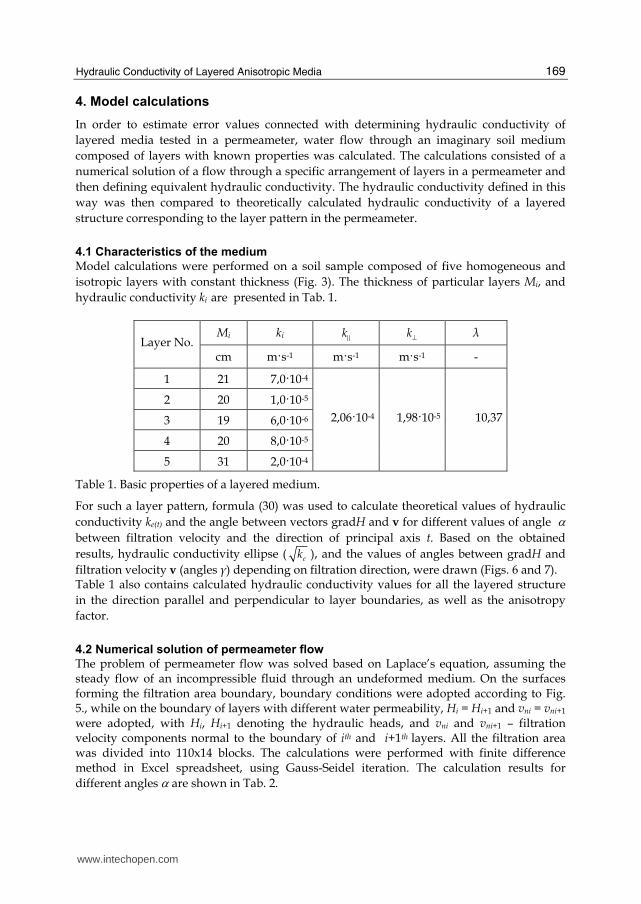
Hydraulic Conductivity of Layered Anisotropic Media
169
4 Model calculations
In order to estimate error values connected with determining hydraulic conductivity of
layered media tested in a permeameter water flow through an imaginary soil medium
composed of layers with known properties was calculated The calculations consisted of a
numerical solution of a flow through a specific arrangement of layers in a permeameter and
then defining equivalent hydraulic conductivity The hydraulic conductivity defined in this
way was then compared to theoretically calculated hydraulic conductivity of a layered
structure corresponding to the layer pattern in the permeameter
41 Characteristics of the medium
Model calculations were performed on a soil sample composed of five homogeneous and
isotropic layers with constant thickness (Fig 3) The thickness of particular layers Mi and
hydraulic conductivity ki are presented in Tab 1
Mi ki kE kperp λ Layer No
cm ms-1 ms-1 ms-1 -
1 21 7010-4
2 20 1010-5
3 19 6010-6
4 20 8010-5
5 31 2010-4
20610-4 19810-5 1037
Table 1 Basic properties of a layered medium
For such a layer pattern formula (30) was used to calculate theoretical values of hydraulic
conductivity ke(t) and the angle between vectors gradH and v for different values of angle α
between filtration velocity and the direction of principal axis t Based on the obtained
results hydraulic conductivity ellipse ( ek ) and the values of angles between gradH and
filtration velocity v (angles γ) depending on filtration direction were drawn (Figs 6 and 7) Table 1 also contains calculated hydraulic conductivity values for all the layered structure
in the direction parallel and perpendicular to layer boundaries as well as the anisotropy
factor
42 Numerical solution of permeameter flow
The problem of permeameter flow was solved based on Laplacersquos equation assuming the steady flow of an incompressible fluid through an undeformed medium On the surfaces forming the filtration area boundary boundary conditions were adopted according to Fig 5 while on the boundary of layers with different water permeability Hi = Hi+1 and vni = vni+1 were adopted with Hi Hi+1 denoting the hydraulic heads and vni and vni+1 ndash filtration velocity components normal to the boundary of ith and i+1th layers All the filtration area was divided into 110x14 blocks The calculations were performed with finite difference method in Excel spreadsheet using Gauss-Seidel iteration The calculation results for
different angles α are shown in Tab 2
wwwintechopencom
Developments in Hydraulic Conductivity Research
170
0000
0002
0004
0006
0008
0010
0012
0014
0016
90
8070
60
50
40
30
20
10
0
350
340
330
320
310
300
290280
270
260250
240
230
220
210
200
190
180
170
160
150
140
130
120
110100
k e
k n
k t
t
n
Fig 6 Hydraulic conductivity ellipse
0
10
20
30
40
50
60
90
8070
60
50
40
30
20
10
0
350
340
330
320
310
300
290280
270
260250
240
230
220
210
200
190
180
170
160
150
140
130
120
110100 γ o
t
n
Fig 7 Angle between hydraulic gradient and filtration velocity depending on filtration direction
wwwintechopencom
Hydraulic Conductivity of Layered Anisotropic Media
171
α γ ke(t) ke(num) ( )e t
k
k
Δ
sr
Q
Q
Δ No
˚ ˚ ms-1 ms-1
1 0 000 20610-4 20610-4 000 000
2 45 3949 36110-5 23110-5 3615 -003
3 50 3537 31610-5 21510-5 3201 382
4 55 3114 28210-5 21310-5 2439 304
5 60 2681 25610-5 21110-5 1740 243
6 65 2243 23610-5 20910-5 1145 168
7 70 1799 22210-5 20710-5 664 109
8 75 1352 21110-5 20410-5 318 061
9 80 903 20410-5 20110-5 108 027
10 85 452 20010-5 19910-5 017 006
11 90 000 19810-5 19810-5 009 000
Table 2 Results of numerical calculations of angle γ between hydraulic gradient and filtration velocity and equivalent hydraulic conductivity ke(num)
It contains theoretically and numerically defined values of equivalent hydraulic conductivity (ke(t) and ke(num)) theoretical values of angles γ between gradH and v error in numerical determination of conductivity in relation to the theoretical value
( ) ( )
( ) ( )
100e t e num
e t e t
k kk
k k
minusΔ = as well as error values ( ) 10005
w d
sr w d
Q Q Q
Q Q Q
Δ minus sdot+= resulting from a
numerical comparison of the quantity of water flowing into (Qd) and out of (Qw) the analysed sample This error was regarded as representative for estimating the accuracy of numerical calculation results
43 Error of hydraulic conductivity determination
In order to estimate the error in determining hydraulic conductivity of a layered medium it
was assumed that the analyses had been performed in a permeameter The tests were
carried out on a layered medium presented in Fig 5 for two flow directions in relation to the
principal axis of permeability tensor One direction corresponded to angle α of 45˚ while
the other - 80˚ The values of equivalent hydraulic conductivity determined correctly
through research should be consistent with Tab 2 and amount to 23110-5 ms-1 and 20110-5
ms-1 respectively Using them later to calculate the hydraulic conductivity in the direction
of the principal axis of permeability tensor from formula (30) one obtains kE = 27510-5 ms-1
and kperp = 19910-5 ms-1 The values calculated in this way were compared with the
theoretical properties of a layered medium presented in Tab1 On can see from the
comparison that the values of kperp are only slightly different (the theoretical value is 198 10-5
m s-1) while in the case of kE the difference is very distinct reaching 75 times One should
also emphasize that such a big difference between these results is not caused by the low
accuracy of numerical flow calculations This is proved by a very small difference in the
discharge of water flowing into and out of the sample no more than 03 (Tab 2)
wwwintechopencom
Developments in Hydraulic Conductivity Research
172
The error in hydraulic conductivity determination in a permeameter may be also caused by
the order of layering In order to estimate its value numerical calculations were performed
for the adopted flow through a layered medium composed of the same layers but arranged
in a different order One should emphasize that according to formula (30) the theoretical
value of equivalent hydraulic conductivity kt does not depend on the layering order The
calculation results for a flow at the angle α = 45˚ and for four layering variants are shown in
Tab 3
ke(t) ke(num) ( )e t
k
k
Δ
sr
Q
Q
Δ Variant
No Layering
order ms-1 ms-1
1 5-1-2-3-4-5 23110-5 3615 -0027
2 5-3-2-4-1-5 21610-5 4014 -0058
3 5-1-4-2-3-5 22710-5 3707 0033
4 5-2-4-3-1-5
36110-5
25510-5 2954 0012
Tab 3 Calculation results of hydraulic conductivity of a layered medium for various layering orders
One can see that depending on the considered variant different results are obtained and
anisotropy-related determination error is contained within wide limits In the analysed
examples it oscillates between 30 and over 40 in relation to the theoretical value In order
to illustrate the causes of differences in hydraulic conductivity calculations of streamline
pattern were also performed For the layering in variants 2 and 4 streamline patterns are
shown in Figs 6 and 7
Fig 6 Streamlines in a sample for layering variant 2
wwwintechopencom
Hydraulic Conductivity of Layered Anisotropic Media
173
0
5
10
15
20
25
-20 0 20 40 60 80 100 120 140 160 180
k5k2 k4 k3
k1 k5
Fig 7 Streamlines in a sample for layering variant 4
A distinct difference in streamline patterns is noticeable Certainly the streamline pattern is basically different from the theoretical streamlines shown in Fig 3 which are polygonal chains composed of straight line segments
5 Conclusion
The presented theoretical discussion has demonstrated that flows in layered media composed
of homogeneous and anisotropic layers cannot be modelled as flows in a homogeneous
medium However it is possible in the case of a structure composed of parallel layers
characterised by homogeneity and orthotropy in two dimensions A flow in such a structure
can be modelled as a flow in a single anisotropic layer In such a case one does not have to
know the permeability parameters and the thickness of particular layers In order to calculate
the flow it is then enough to know the hydraulic conductivity in the direction parallel and
perpendicular to layering These values can be determined theoretically by analysing a flow
through such a layered structure in any two directions to the boundary surfaces of the layers
However the calculation results point to a possibility of vital errors occurring while
determining the permeability of layered media in a permeameter This regards those tests
where flow occurs in the direction diagonal to layering The occurrence of major determination
errors is connected with a failure to maintain the appropriate directions of gradH and v and
the proper geometric shape of the sample in a permeameter The value of those errors depends
on the value of anisotropy factor λ and the angular difference between gradH and v In the
performed model calculations of a flow through a layered medium with anisotropy factor
λ = 1037 the obtained value of hydraulic conductivity in the direction perpendicular to layer
boundary was very close to the theoretical one while in the parallel direction it was 75 times
underrated Clearly then such analyses result in very serious underrating of anisotropy factor
The conducted calculations also reveal a considerable influence of layering order on the
determination results of hydraulic conductivity in a permeameter The differences obtained
from model calculations oscillated between c 30 to 40 in relation to the theoretical value
wwwintechopencom
Developments in Hydraulic Conductivity Research
174
To sum up one should clearly state that the correct determination results of hydraulic conductivity of layered media can be obtained by forcing a flow in the direction parallel and perpendicular to layering Any departures from this rule may lead to very large determination errors
6 References
Batu V (1998) Aquifer hydraulics A comprehensive quide to hydrogeologic data analysis John Wiley amp Sons ISBN 0-471-18502-7 New York
Bear J (1972) Dynamics of Fluids in Porous Media Dover Publications ISBN 0-486-65675-6 Cheng A (2000) Multilayered aquifer systems Fundamentals and applications Marcel Dekker
Inc ISBN 0-8247-9875-9 New York Basel Mozely PS amp Davis JM (1996) Relationship between oriented calcite concretions and
permeability correlation structure in alluvial aquifer Sierra Ladrones Formation New Mexiko Journal of Sedimentary Research Vol 66 No 1 (January 1996) pp (11-16) ISSN 1527-1404
Renard Ph Genty A Stauffer F (2001) Laboratory determination of full permeability tensor Journal of Geophysical Research Vol 106 No B11 (November 2001) pp 26443-26452 ISSN 0148-0227
Rogoi M (2007) Dynamika woacuted podziemnych GIG ISBN 978-83-87610-97-5 Katowice Snow D T (1969) Anisotropic permeability of fractured media Water Resour Res 5(6)
1273-1289 ISSN 0043-1397
wwwintechopencom
Developments in Hydraulic Conductivity ResearchEdited by Dr Oagile Dikinya
ISBN 978-953-307-470-2Hard cover 270 pagesPublisher InTechPublished online 28 February 2011Published in print edition February 2011
InTech EuropeUniversity Campus STeP Ri Slavka Krautzeka 83A 51000 Rijeka Croatia Phone +385 (51) 770 447 Fax +385 (51) 686 166wwwintechopencom
InTech ChinaUnit 405 Office Block Hotel Equatorial Shanghai No65 Yan An Road (West) Shanghai 200040 China Phone +86-21-62489820 Fax +86-21-62489821
This book provides the state of the art of the investigation and the in-depth analysis of hydraulic conductivityfrom the theoretical to semi-empirical models perspective as well as policy development associated withmanagement of land resources emanating from drainage-problem soils A group of international expertscontributed to the development of this book It is envisaged that this thought provoking book will excite andappeal to academics engineers researchers and University students who seek to explore the breadth and in-depth knowledge about hydraulic conductivity Investigation into hydraulic conductivity is important to theunderstanding of the movement of solutes and water in the terrestrial environment Transport of these fluidshas various implications on the ecology and quality of environment and subsequently sustenance of livelihoodsof the increasing world population In particular water flow in the vadose zone is of fundamental importance togeoscientists soil scientists hydrogeologists and hydrologists and allied professionals
How to referenceIn order to correctly reference this scholarly work feel free to copy and paste the following
Stanisław Żak (2011) Hydraulic Conductivity of Layered Anisotropic Media Developments in HydraulicConductivity Research Dr Oagile Dikinya (Ed) ISBN 978-953-307-470-2 InTech Available fromhttpwwwintechopencombooksdevelopments-in-hydraulic-conductivity-researchhydraulic-conductivity-of-layered-anisotropic-media
copy 2011 The Author(s) Licensee IntechOpen This chapter is distributedunder the terms of the Creative Commons Attribution-NonCommercial-ShareAlike-30 License which permits use distribution and reproduction fornon-commercial purposes provided the original is properly cited andderivative works building on this content are distributed under the samelicense

Developments in Hydraulic Conductivity Research
170
0000
0002
0004
0006
0008
0010
0012
0014
0016
90
8070
60
50
40
30
20
10
0
350
340
330
320
310
300
290280
270
260250
240
230
220
210
200
190
180
170
160
150
140
130
120
110100
k e
k n
k t
t
n
Fig 6 Hydraulic conductivity ellipse
0
10
20
30
40
50
60
90
8070
60
50
40
30
20
10
0
350
340
330
320
310
300
290280
270
260250
240
230
220
210
200
190
180
170
160
150
140
130
120
110100 γ o
t
n
Fig 7 Angle between hydraulic gradient and filtration velocity depending on filtration direction
wwwintechopencom
Hydraulic Conductivity of Layered Anisotropic Media
171
α γ ke(t) ke(num) ( )e t
k
k
Δ
sr
Q
Q
Δ No
˚ ˚ ms-1 ms-1
1 0 000 20610-4 20610-4 000 000
2 45 3949 36110-5 23110-5 3615 -003
3 50 3537 31610-5 21510-5 3201 382
4 55 3114 28210-5 21310-5 2439 304
5 60 2681 25610-5 21110-5 1740 243
6 65 2243 23610-5 20910-5 1145 168
7 70 1799 22210-5 20710-5 664 109
8 75 1352 21110-5 20410-5 318 061
9 80 903 20410-5 20110-5 108 027
10 85 452 20010-5 19910-5 017 006
11 90 000 19810-5 19810-5 009 000
Table 2 Results of numerical calculations of angle γ between hydraulic gradient and filtration velocity and equivalent hydraulic conductivity ke(num)
It contains theoretically and numerically defined values of equivalent hydraulic conductivity (ke(t) and ke(num)) theoretical values of angles γ between gradH and v error in numerical determination of conductivity in relation to the theoretical value
( ) ( )
( ) ( )
100e t e num
e t e t
k kk
k k
minusΔ = as well as error values ( ) 10005
w d
sr w d
Q Q Q
Q Q Q
Δ minus sdot+= resulting from a
numerical comparison of the quantity of water flowing into (Qd) and out of (Qw) the analysed sample This error was regarded as representative for estimating the accuracy of numerical calculation results
43 Error of hydraulic conductivity determination
In order to estimate the error in determining hydraulic conductivity of a layered medium it
was assumed that the analyses had been performed in a permeameter The tests were
carried out on a layered medium presented in Fig 5 for two flow directions in relation to the
principal axis of permeability tensor One direction corresponded to angle α of 45˚ while
the other - 80˚ The values of equivalent hydraulic conductivity determined correctly
through research should be consistent with Tab 2 and amount to 23110-5 ms-1 and 20110-5
ms-1 respectively Using them later to calculate the hydraulic conductivity in the direction
of the principal axis of permeability tensor from formula (30) one obtains kE = 27510-5 ms-1
and kperp = 19910-5 ms-1 The values calculated in this way were compared with the
theoretical properties of a layered medium presented in Tab1 On can see from the
comparison that the values of kperp are only slightly different (the theoretical value is 198 10-5
m s-1) while in the case of kE the difference is very distinct reaching 75 times One should
also emphasize that such a big difference between these results is not caused by the low
accuracy of numerical flow calculations This is proved by a very small difference in the
discharge of water flowing into and out of the sample no more than 03 (Tab 2)
wwwintechopencom
Developments in Hydraulic Conductivity Research
172
The error in hydraulic conductivity determination in a permeameter may be also caused by
the order of layering In order to estimate its value numerical calculations were performed
for the adopted flow through a layered medium composed of the same layers but arranged
in a different order One should emphasize that according to formula (30) the theoretical
value of equivalent hydraulic conductivity kt does not depend on the layering order The
calculation results for a flow at the angle α = 45˚ and for four layering variants are shown in
Tab 3
ke(t) ke(num) ( )e t
k
k
Δ
sr
Q
Q
Δ Variant
No Layering
order ms-1 ms-1
1 5-1-2-3-4-5 23110-5 3615 -0027
2 5-3-2-4-1-5 21610-5 4014 -0058
3 5-1-4-2-3-5 22710-5 3707 0033
4 5-2-4-3-1-5
36110-5
25510-5 2954 0012
Tab 3 Calculation results of hydraulic conductivity of a layered medium for various layering orders
One can see that depending on the considered variant different results are obtained and
anisotropy-related determination error is contained within wide limits In the analysed
examples it oscillates between 30 and over 40 in relation to the theoretical value In order
to illustrate the causes of differences in hydraulic conductivity calculations of streamline
pattern were also performed For the layering in variants 2 and 4 streamline patterns are
shown in Figs 6 and 7
Fig 6 Streamlines in a sample for layering variant 2
wwwintechopencom
Hydraulic Conductivity of Layered Anisotropic Media
173
0
5
10
15
20
25
-20 0 20 40 60 80 100 120 140 160 180
k5k2 k4 k3
k1 k5
Fig 7 Streamlines in a sample for layering variant 4
A distinct difference in streamline patterns is noticeable Certainly the streamline pattern is basically different from the theoretical streamlines shown in Fig 3 which are polygonal chains composed of straight line segments
5 Conclusion
The presented theoretical discussion has demonstrated that flows in layered media composed
of homogeneous and anisotropic layers cannot be modelled as flows in a homogeneous
medium However it is possible in the case of a structure composed of parallel layers
characterised by homogeneity and orthotropy in two dimensions A flow in such a structure
can be modelled as a flow in a single anisotropic layer In such a case one does not have to
know the permeability parameters and the thickness of particular layers In order to calculate
the flow it is then enough to know the hydraulic conductivity in the direction parallel and
perpendicular to layering These values can be determined theoretically by analysing a flow
through such a layered structure in any two directions to the boundary surfaces of the layers
However the calculation results point to a possibility of vital errors occurring while
determining the permeability of layered media in a permeameter This regards those tests
where flow occurs in the direction diagonal to layering The occurrence of major determination
errors is connected with a failure to maintain the appropriate directions of gradH and v and
the proper geometric shape of the sample in a permeameter The value of those errors depends
on the value of anisotropy factor λ and the angular difference between gradH and v In the
performed model calculations of a flow through a layered medium with anisotropy factor
λ = 1037 the obtained value of hydraulic conductivity in the direction perpendicular to layer
boundary was very close to the theoretical one while in the parallel direction it was 75 times
underrated Clearly then such analyses result in very serious underrating of anisotropy factor
The conducted calculations also reveal a considerable influence of layering order on the
determination results of hydraulic conductivity in a permeameter The differences obtained
from model calculations oscillated between c 30 to 40 in relation to the theoretical value
wwwintechopencom
Developments in Hydraulic Conductivity Research
174
To sum up one should clearly state that the correct determination results of hydraulic conductivity of layered media can be obtained by forcing a flow in the direction parallel and perpendicular to layering Any departures from this rule may lead to very large determination errors
6 References
Batu V (1998) Aquifer hydraulics A comprehensive quide to hydrogeologic data analysis John Wiley amp Sons ISBN 0-471-18502-7 New York
Bear J (1972) Dynamics of Fluids in Porous Media Dover Publications ISBN 0-486-65675-6 Cheng A (2000) Multilayered aquifer systems Fundamentals and applications Marcel Dekker
Inc ISBN 0-8247-9875-9 New York Basel Mozely PS amp Davis JM (1996) Relationship between oriented calcite concretions and
permeability correlation structure in alluvial aquifer Sierra Ladrones Formation New Mexiko Journal of Sedimentary Research Vol 66 No 1 (January 1996) pp (11-16) ISSN 1527-1404
Renard Ph Genty A Stauffer F (2001) Laboratory determination of full permeability tensor Journal of Geophysical Research Vol 106 No B11 (November 2001) pp 26443-26452 ISSN 0148-0227
Rogoi M (2007) Dynamika woacuted podziemnych GIG ISBN 978-83-87610-97-5 Katowice Snow D T (1969) Anisotropic permeability of fractured media Water Resour Res 5(6)
1273-1289 ISSN 0043-1397
wwwintechopencom
Developments in Hydraulic Conductivity ResearchEdited by Dr Oagile Dikinya
ISBN 978-953-307-470-2Hard cover 270 pagesPublisher InTechPublished online 28 February 2011Published in print edition February 2011
InTech EuropeUniversity Campus STeP Ri Slavka Krautzeka 83A 51000 Rijeka Croatia Phone +385 (51) 770 447 Fax +385 (51) 686 166wwwintechopencom
InTech ChinaUnit 405 Office Block Hotel Equatorial Shanghai No65 Yan An Road (West) Shanghai 200040 China Phone +86-21-62489820 Fax +86-21-62489821
This book provides the state of the art of the investigation and the in-depth analysis of hydraulic conductivityfrom the theoretical to semi-empirical models perspective as well as policy development associated withmanagement of land resources emanating from drainage-problem soils A group of international expertscontributed to the development of this book It is envisaged that this thought provoking book will excite andappeal to academics engineers researchers and University students who seek to explore the breadth and in-depth knowledge about hydraulic conductivity Investigation into hydraulic conductivity is important to theunderstanding of the movement of solutes and water in the terrestrial environment Transport of these fluidshas various implications on the ecology and quality of environment and subsequently sustenance of livelihoodsof the increasing world population In particular water flow in the vadose zone is of fundamental importance togeoscientists soil scientists hydrogeologists and hydrologists and allied professionals
How to referenceIn order to correctly reference this scholarly work feel free to copy and paste the following
Stanisław Żak (2011) Hydraulic Conductivity of Layered Anisotropic Media Developments in HydraulicConductivity Research Dr Oagile Dikinya (Ed) ISBN 978-953-307-470-2 InTech Available fromhttpwwwintechopencombooksdevelopments-in-hydraulic-conductivity-researchhydraulic-conductivity-of-layered-anisotropic-media
copy 2011 The Author(s) Licensee IntechOpen This chapter is distributedunder the terms of the Creative Commons Attribution-NonCommercial-ShareAlike-30 License which permits use distribution and reproduction fornon-commercial purposes provided the original is properly cited andderivative works building on this content are distributed under the samelicense

Hydraulic Conductivity of Layered Anisotropic Media
171
α γ ke(t) ke(num) ( )e t
k
k
Δ
sr
Q
Q
Δ No
˚ ˚ ms-1 ms-1
1 0 000 20610-4 20610-4 000 000
2 45 3949 36110-5 23110-5 3615 -003
3 50 3537 31610-5 21510-5 3201 382
4 55 3114 28210-5 21310-5 2439 304
5 60 2681 25610-5 21110-5 1740 243
6 65 2243 23610-5 20910-5 1145 168
7 70 1799 22210-5 20710-5 664 109
8 75 1352 21110-5 20410-5 318 061
9 80 903 20410-5 20110-5 108 027
10 85 452 20010-5 19910-5 017 006
11 90 000 19810-5 19810-5 009 000
Table 2 Results of numerical calculations of angle γ between hydraulic gradient and filtration velocity and equivalent hydraulic conductivity ke(num)
It contains theoretically and numerically defined values of equivalent hydraulic conductivity (ke(t) and ke(num)) theoretical values of angles γ between gradH and v error in numerical determination of conductivity in relation to the theoretical value
( ) ( )
( ) ( )
100e t e num
e t e t
k kk
k k
minusΔ = as well as error values ( ) 10005
w d
sr w d
Q Q Q
Q Q Q
Δ minus sdot+= resulting from a
numerical comparison of the quantity of water flowing into (Qd) and out of (Qw) the analysed sample This error was regarded as representative for estimating the accuracy of numerical calculation results
43 Error of hydraulic conductivity determination
In order to estimate the error in determining hydraulic conductivity of a layered medium it
was assumed that the analyses had been performed in a permeameter The tests were
carried out on a layered medium presented in Fig 5 for two flow directions in relation to the
principal axis of permeability tensor One direction corresponded to angle α of 45˚ while
the other - 80˚ The values of equivalent hydraulic conductivity determined correctly
through research should be consistent with Tab 2 and amount to 23110-5 ms-1 and 20110-5
ms-1 respectively Using them later to calculate the hydraulic conductivity in the direction
of the principal axis of permeability tensor from formula (30) one obtains kE = 27510-5 ms-1
and kperp = 19910-5 ms-1 The values calculated in this way were compared with the
theoretical properties of a layered medium presented in Tab1 On can see from the
comparison that the values of kperp are only slightly different (the theoretical value is 198 10-5
m s-1) while in the case of kE the difference is very distinct reaching 75 times One should
also emphasize that such a big difference between these results is not caused by the low
accuracy of numerical flow calculations This is proved by a very small difference in the
discharge of water flowing into and out of the sample no more than 03 (Tab 2)
wwwintechopencom
Developments in Hydraulic Conductivity Research
172
The error in hydraulic conductivity determination in a permeameter may be also caused by
the order of layering In order to estimate its value numerical calculations were performed
for the adopted flow through a layered medium composed of the same layers but arranged
in a different order One should emphasize that according to formula (30) the theoretical
value of equivalent hydraulic conductivity kt does not depend on the layering order The
calculation results for a flow at the angle α = 45˚ and for four layering variants are shown in
Tab 3
ke(t) ke(num) ( )e t
k
k
Δ
sr
Q
Q
Δ Variant
No Layering
order ms-1 ms-1
1 5-1-2-3-4-5 23110-5 3615 -0027
2 5-3-2-4-1-5 21610-5 4014 -0058
3 5-1-4-2-3-5 22710-5 3707 0033
4 5-2-4-3-1-5
36110-5
25510-5 2954 0012
Tab 3 Calculation results of hydraulic conductivity of a layered medium for various layering orders
One can see that depending on the considered variant different results are obtained and
anisotropy-related determination error is contained within wide limits In the analysed
examples it oscillates between 30 and over 40 in relation to the theoretical value In order
to illustrate the causes of differences in hydraulic conductivity calculations of streamline
pattern were also performed For the layering in variants 2 and 4 streamline patterns are
shown in Figs 6 and 7
Fig 6 Streamlines in a sample for layering variant 2
wwwintechopencom
Hydraulic Conductivity of Layered Anisotropic Media
173
0
5
10
15
20
25
-20 0 20 40 60 80 100 120 140 160 180
k5k2 k4 k3
k1 k5
Fig 7 Streamlines in a sample for layering variant 4
A distinct difference in streamline patterns is noticeable Certainly the streamline pattern is basically different from the theoretical streamlines shown in Fig 3 which are polygonal chains composed of straight line segments
5 Conclusion
The presented theoretical discussion has demonstrated that flows in layered media composed
of homogeneous and anisotropic layers cannot be modelled as flows in a homogeneous
medium However it is possible in the case of a structure composed of parallel layers
characterised by homogeneity and orthotropy in two dimensions A flow in such a structure
can be modelled as a flow in a single anisotropic layer In such a case one does not have to
know the permeability parameters and the thickness of particular layers In order to calculate
the flow it is then enough to know the hydraulic conductivity in the direction parallel and
perpendicular to layering These values can be determined theoretically by analysing a flow
through such a layered structure in any two directions to the boundary surfaces of the layers
However the calculation results point to a possibility of vital errors occurring while
determining the permeability of layered media in a permeameter This regards those tests
where flow occurs in the direction diagonal to layering The occurrence of major determination
errors is connected with a failure to maintain the appropriate directions of gradH and v and
the proper geometric shape of the sample in a permeameter The value of those errors depends
on the value of anisotropy factor λ and the angular difference between gradH and v In the
performed model calculations of a flow through a layered medium with anisotropy factor
λ = 1037 the obtained value of hydraulic conductivity in the direction perpendicular to layer
boundary was very close to the theoretical one while in the parallel direction it was 75 times
underrated Clearly then such analyses result in very serious underrating of anisotropy factor
The conducted calculations also reveal a considerable influence of layering order on the
determination results of hydraulic conductivity in a permeameter The differences obtained
from model calculations oscillated between c 30 to 40 in relation to the theoretical value
wwwintechopencom
Developments in Hydraulic Conductivity Research
174
To sum up one should clearly state that the correct determination results of hydraulic conductivity of layered media can be obtained by forcing a flow in the direction parallel and perpendicular to layering Any departures from this rule may lead to very large determination errors
6 References
Batu V (1998) Aquifer hydraulics A comprehensive quide to hydrogeologic data analysis John Wiley amp Sons ISBN 0-471-18502-7 New York
Bear J (1972) Dynamics of Fluids in Porous Media Dover Publications ISBN 0-486-65675-6 Cheng A (2000) Multilayered aquifer systems Fundamentals and applications Marcel Dekker
Inc ISBN 0-8247-9875-9 New York Basel Mozely PS amp Davis JM (1996) Relationship between oriented calcite concretions and
permeability correlation structure in alluvial aquifer Sierra Ladrones Formation New Mexiko Journal of Sedimentary Research Vol 66 No 1 (January 1996) pp (11-16) ISSN 1527-1404
Renard Ph Genty A Stauffer F (2001) Laboratory determination of full permeability tensor Journal of Geophysical Research Vol 106 No B11 (November 2001) pp 26443-26452 ISSN 0148-0227
Rogoi M (2007) Dynamika woacuted podziemnych GIG ISBN 978-83-87610-97-5 Katowice Snow D T (1969) Anisotropic permeability of fractured media Water Resour Res 5(6)
1273-1289 ISSN 0043-1397
wwwintechopencom
Developments in Hydraulic Conductivity ResearchEdited by Dr Oagile Dikinya
ISBN 978-953-307-470-2Hard cover 270 pagesPublisher InTechPublished online 28 February 2011Published in print edition February 2011
InTech EuropeUniversity Campus STeP Ri Slavka Krautzeka 83A 51000 Rijeka Croatia Phone +385 (51) 770 447 Fax +385 (51) 686 166wwwintechopencom
InTech ChinaUnit 405 Office Block Hotel Equatorial Shanghai No65 Yan An Road (West) Shanghai 200040 China Phone +86-21-62489820 Fax +86-21-62489821
This book provides the state of the art of the investigation and the in-depth analysis of hydraulic conductivityfrom the theoretical to semi-empirical models perspective as well as policy development associated withmanagement of land resources emanating from drainage-problem soils A group of international expertscontributed to the development of this book It is envisaged that this thought provoking book will excite andappeal to academics engineers researchers and University students who seek to explore the breadth and in-depth knowledge about hydraulic conductivity Investigation into hydraulic conductivity is important to theunderstanding of the movement of solutes and water in the terrestrial environment Transport of these fluidshas various implications on the ecology and quality of environment and subsequently sustenance of livelihoodsof the increasing world population In particular water flow in the vadose zone is of fundamental importance togeoscientists soil scientists hydrogeologists and hydrologists and allied professionals
How to referenceIn order to correctly reference this scholarly work feel free to copy and paste the following
Stanisław Żak (2011) Hydraulic Conductivity of Layered Anisotropic Media Developments in HydraulicConductivity Research Dr Oagile Dikinya (Ed) ISBN 978-953-307-470-2 InTech Available fromhttpwwwintechopencombooksdevelopments-in-hydraulic-conductivity-researchhydraulic-conductivity-of-layered-anisotropic-media
copy 2011 The Author(s) Licensee IntechOpen This chapter is distributedunder the terms of the Creative Commons Attribution-NonCommercial-ShareAlike-30 License which permits use distribution and reproduction fornon-commercial purposes provided the original is properly cited andderivative works building on this content are distributed under the samelicense
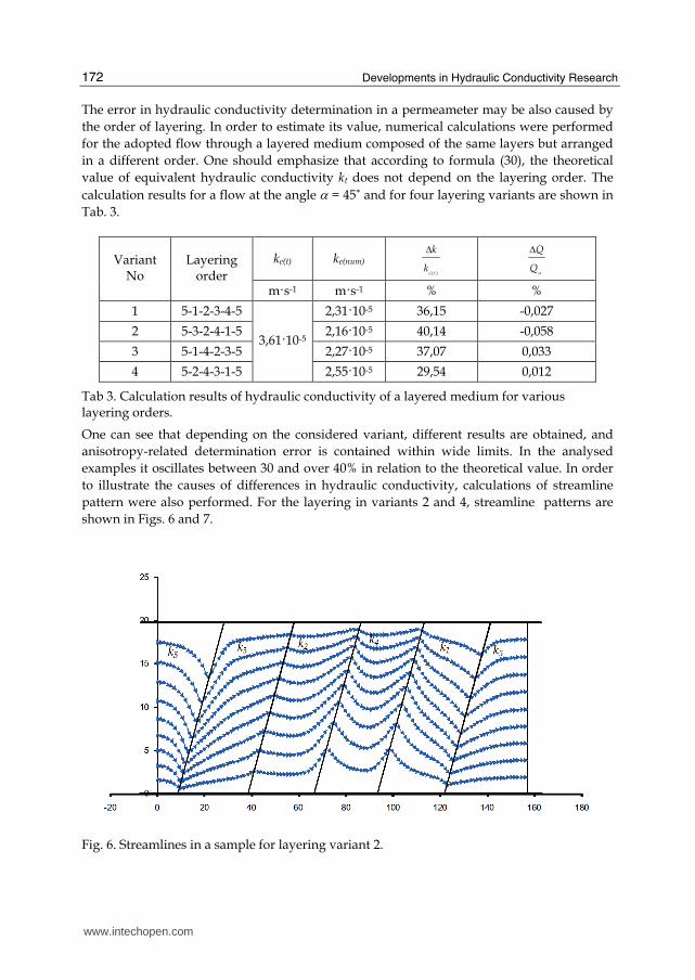
Developments in Hydraulic Conductivity Research
172
The error in hydraulic conductivity determination in a permeameter may be also caused by
the order of layering In order to estimate its value numerical calculations were performed
for the adopted flow through a layered medium composed of the same layers but arranged
in a different order One should emphasize that according to formula (30) the theoretical
value of equivalent hydraulic conductivity kt does not depend on the layering order The
calculation results for a flow at the angle α = 45˚ and for four layering variants are shown in
Tab 3
ke(t) ke(num) ( )e t
k
k
Δ
sr
Q
Q
Δ Variant
No Layering
order ms-1 ms-1
1 5-1-2-3-4-5 23110-5 3615 -0027
2 5-3-2-4-1-5 21610-5 4014 -0058
3 5-1-4-2-3-5 22710-5 3707 0033
4 5-2-4-3-1-5
36110-5
25510-5 2954 0012
Tab 3 Calculation results of hydraulic conductivity of a layered medium for various layering orders
One can see that depending on the considered variant different results are obtained and
anisotropy-related determination error is contained within wide limits In the analysed
examples it oscillates between 30 and over 40 in relation to the theoretical value In order
to illustrate the causes of differences in hydraulic conductivity calculations of streamline
pattern were also performed For the layering in variants 2 and 4 streamline patterns are
shown in Figs 6 and 7
Fig 6 Streamlines in a sample for layering variant 2
wwwintechopencom
Hydraulic Conductivity of Layered Anisotropic Media
173
0
5
10
15
20
25
-20 0 20 40 60 80 100 120 140 160 180
k5k2 k4 k3
k1 k5
Fig 7 Streamlines in a sample for layering variant 4
A distinct difference in streamline patterns is noticeable Certainly the streamline pattern is basically different from the theoretical streamlines shown in Fig 3 which are polygonal chains composed of straight line segments
5 Conclusion
The presented theoretical discussion has demonstrated that flows in layered media composed
of homogeneous and anisotropic layers cannot be modelled as flows in a homogeneous
medium However it is possible in the case of a structure composed of parallel layers
characterised by homogeneity and orthotropy in two dimensions A flow in such a structure
can be modelled as a flow in a single anisotropic layer In such a case one does not have to
know the permeability parameters and the thickness of particular layers In order to calculate
the flow it is then enough to know the hydraulic conductivity in the direction parallel and
perpendicular to layering These values can be determined theoretically by analysing a flow
through such a layered structure in any two directions to the boundary surfaces of the layers
However the calculation results point to a possibility of vital errors occurring while
determining the permeability of layered media in a permeameter This regards those tests
where flow occurs in the direction diagonal to layering The occurrence of major determination
errors is connected with a failure to maintain the appropriate directions of gradH and v and
the proper geometric shape of the sample in a permeameter The value of those errors depends
on the value of anisotropy factor λ and the angular difference between gradH and v In the
performed model calculations of a flow through a layered medium with anisotropy factor
λ = 1037 the obtained value of hydraulic conductivity in the direction perpendicular to layer
boundary was very close to the theoretical one while in the parallel direction it was 75 times
underrated Clearly then such analyses result in very serious underrating of anisotropy factor
The conducted calculations also reveal a considerable influence of layering order on the
determination results of hydraulic conductivity in a permeameter The differences obtained
from model calculations oscillated between c 30 to 40 in relation to the theoretical value
wwwintechopencom
Developments in Hydraulic Conductivity Research
174
To sum up one should clearly state that the correct determination results of hydraulic conductivity of layered media can be obtained by forcing a flow in the direction parallel and perpendicular to layering Any departures from this rule may lead to very large determination errors
6 References
Batu V (1998) Aquifer hydraulics A comprehensive quide to hydrogeologic data analysis John Wiley amp Sons ISBN 0-471-18502-7 New York
Bear J (1972) Dynamics of Fluids in Porous Media Dover Publications ISBN 0-486-65675-6 Cheng A (2000) Multilayered aquifer systems Fundamentals and applications Marcel Dekker
Inc ISBN 0-8247-9875-9 New York Basel Mozely PS amp Davis JM (1996) Relationship between oriented calcite concretions and
permeability correlation structure in alluvial aquifer Sierra Ladrones Formation New Mexiko Journal of Sedimentary Research Vol 66 No 1 (January 1996) pp (11-16) ISSN 1527-1404
Renard Ph Genty A Stauffer F (2001) Laboratory determination of full permeability tensor Journal of Geophysical Research Vol 106 No B11 (November 2001) pp 26443-26452 ISSN 0148-0227
Rogoi M (2007) Dynamika woacuted podziemnych GIG ISBN 978-83-87610-97-5 Katowice Snow D T (1969) Anisotropic permeability of fractured media Water Resour Res 5(6)
1273-1289 ISSN 0043-1397
wwwintechopencom
Developments in Hydraulic Conductivity ResearchEdited by Dr Oagile Dikinya
ISBN 978-953-307-470-2Hard cover 270 pagesPublisher InTechPublished online 28 February 2011Published in print edition February 2011
InTech EuropeUniversity Campus STeP Ri Slavka Krautzeka 83A 51000 Rijeka Croatia Phone +385 (51) 770 447 Fax +385 (51) 686 166wwwintechopencom
InTech ChinaUnit 405 Office Block Hotel Equatorial Shanghai No65 Yan An Road (West) Shanghai 200040 China Phone +86-21-62489820 Fax +86-21-62489821
This book provides the state of the art of the investigation and the in-depth analysis of hydraulic conductivityfrom the theoretical to semi-empirical models perspective as well as policy development associated withmanagement of land resources emanating from drainage-problem soils A group of international expertscontributed to the development of this book It is envisaged that this thought provoking book will excite andappeal to academics engineers researchers and University students who seek to explore the breadth and in-depth knowledge about hydraulic conductivity Investigation into hydraulic conductivity is important to theunderstanding of the movement of solutes and water in the terrestrial environment Transport of these fluidshas various implications on the ecology and quality of environment and subsequently sustenance of livelihoodsof the increasing world population In particular water flow in the vadose zone is of fundamental importance togeoscientists soil scientists hydrogeologists and hydrologists and allied professionals
How to referenceIn order to correctly reference this scholarly work feel free to copy and paste the following
Stanisław Żak (2011) Hydraulic Conductivity of Layered Anisotropic Media Developments in HydraulicConductivity Research Dr Oagile Dikinya (Ed) ISBN 978-953-307-470-2 InTech Available fromhttpwwwintechopencombooksdevelopments-in-hydraulic-conductivity-researchhydraulic-conductivity-of-layered-anisotropic-media
copy 2011 The Author(s) Licensee IntechOpen This chapter is distributedunder the terms of the Creative Commons Attribution-NonCommercial-ShareAlike-30 License which permits use distribution and reproduction fornon-commercial purposes provided the original is properly cited andderivative works building on this content are distributed under the samelicense
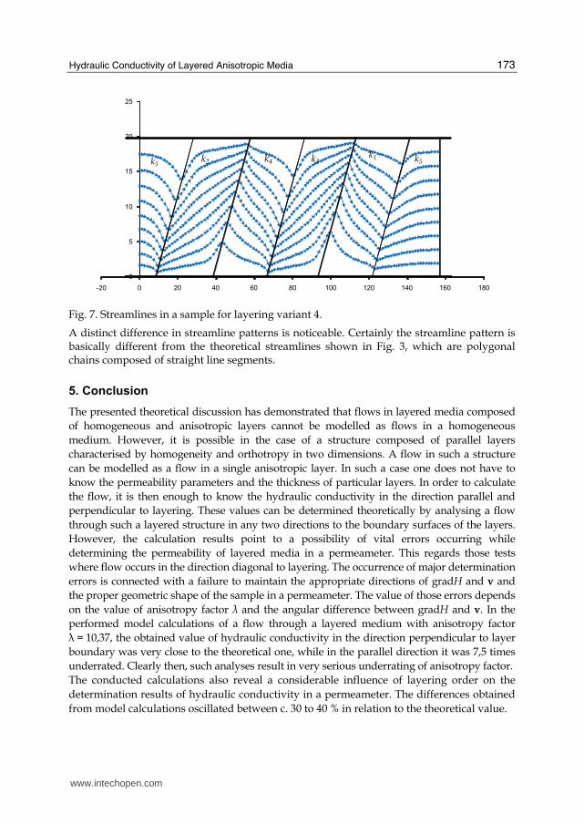

copy 2011 The Author(s) Licensee IntechOpen This chapter is distributedunder the terms of the Creative Commons Attribution-NonCommercial-ShareAlike-30 License which permits use distribution and reproduction fornon-commercial purposes provided the original is properly cited andderivative works building on this content are distributed under the samelicense