hydraulic cylinder 7mpa nominal pressure series chn · hydraulic cylinder 7mpa nominal pressure...
TRANSCRIPT

Hydraulic Cylinder7MPa Nominal Pressure
Series CHNø20, ø25, ø32, ø40
Our Series CHN stainless steel tube hydraulic cylinder comes in four small bore sizes and can handle nominal pressures of up to 7MPa.
CAT.ES110-11 A

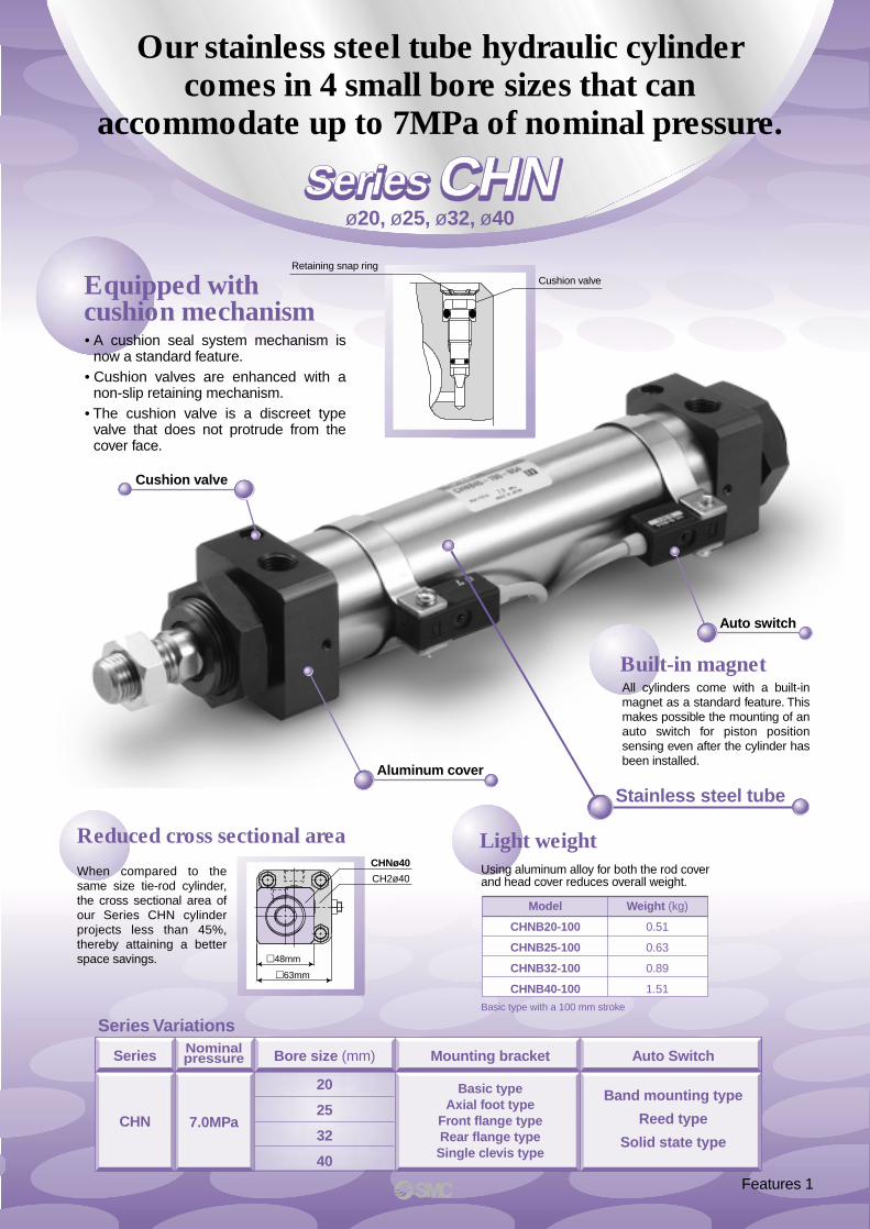
Our stainless steel tube hydraulic cylindercomes in 4 small bore sizes that can
accommodate up to 7MPa of nominal pressure.
Equipped withcushion mechanism
Light weight
Stainless steel tube
Auto switch
Cushion valve
Built-in magnet
Series
CHN
Nominalpressure
7.0MPa
Bore size (mm)
20
25
32
40
Mounting bracket
Basic typeAxial foot type
Front flange typeRear flange typeSingle clevis type
Model
CHNB20-100
CHNB25-100
CHNB32-100
CHNB40-100
Weight (kg)
0.51
0.63
0.89
1.51
Basic type with a 100 mm stroke
Series Variations
Reduced cross sectional area
Aluminum cover
ø20, ø25, ø32, ø40
Auto Switch
Band mounting type
Reed type
Solid state type
CHN Series CHN Series
Features 1
48mm
63mm
Cushion valve
Retaining snap ring
CHNø40
CH2ø40When compared to the same size tie-rod cylinder, the cross sectional area of our Series CHN cylinder projects less than 45%, thereby attaining a better space savings.
• A cushion seal system mechanism is now a standard feature.
• Cushion valves are enhanced with a non-slip retaining mechanism.
• The cushion valve is a discreet type valve that does not protrude from the cover face.
All cylinders come with a built-in magnet as a standard feature. This makes possible the mounting of an auto switch for piston position sensing even after the cylinder has been installed.
Using aluminum alloy for both the rod cover and head cover reduces overall weight.
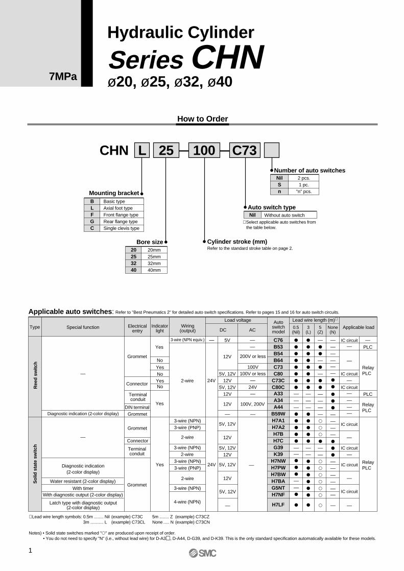
2 pcs.1 pc.
"n" pcs.
NilSn
Number of auto switches
Without auto switchNilAuto switch type
Bore size Cylinder stroke (mm)Refer to the standard stroke table on page 2.
1
Hydraulic Cylinder
Series CHNø20, ø25, ø32, ø40
CHN 25 100 C73L
20253240
20mm25mm32mm40mm
Mounting bracketBLFGC
Basic typeAxial foot typeFront flange typeRear flange typeSingle clevis type
Applicable auto switches:
Type Electricalentry
Connector
Connector
3-wire (NPN equiv.)
Load voltage
——
ACDC
Lead wire length (m)∗
0.5(Nil)
3(L)
5(Z)
None(N)
———
——————
IC circuit—
Applicable load
100V or less—
24V—
200V or less
5V
Yes
Yes
Yes
Diagnostic indication (2-color display)
Diagnostic indication(2-color display)
With diagnostic output (2-color display)
Latch type with diagnostic output(2-color display)
With timer
Water resistant (2-color display)
YesNoYesNo
2-wire
2-wire
2-wire
2-wire
IC circuit
—IC circuit
—
Ree
d s
witc
hS
olid
sta
te s
witc
h
C76B53B54B64C73C80
C73CC80C
H7LF
—No
—
—
∗ Lead wire length symbols: 0.5m ........ Nil (example) C73C 5m ........ Z (example) C73CZ3m ........... L (example) C73CL None ..... N (example) C73CN
Notes) • Solid state switches marked "" are produced upon receipt of order.• You do not need to specify "N" (i.e., without lead wire) for D-A3, D-A44, D-G39, and D-K39. This is the only standard specification automatically available for these models.
RelayPLC
RelayPLC
RelayPLC
PLC
PLC
12V
24V
—
24V
Grommet
Grommet
Grommet
DIN terminal
Terminalconduit
Terminalconduit
Grommet
Wiring(output)
Special functionAuto
switchmodel
—
100V
100V, 200V
—
IC circuit
—
3-wire (PNP)
3-wire (PNP)
3-wire (NPN)
3-wire (NPN)
3-wire (NPN)
3-wire (NPN)
4-wire (NPN)
5V, 12V12V
5V, 12V12V
5V, 12V12V
5V, 12V
12V
12V
5V, 12V
5V, 12V
12V
—
—
A33A34A44
B59WH7A1H7A2H7BH7CG39K39
H7NWH7PWH7BWH7BAG5NTH7NF
———————
—————
——————
——————————
———
—
—
—
—
IC circuit
IC circuit
IC circuit
—
Refer to "Best Pneumatics 2" for detailed auto switch specifications. Refer to pages 15 and 16 for auto switch circuits.
7MPa
How to Order
∗ Select applicable auto switches from the table below.
Indicatorlight

2
Hydraulic Cylinder: 7MPa Series CHN
Action
Fluid
Nominal pressure
Proof pressure
Maximum allowable pressure
Minimum operating pressure
Ambient and fluid temperature
Piston speed
Cushion
Rod end thread
Thread tolerance
Double acting/Single rod
Hydraulic fluid
7MPa
10.5MPa
9MPa
0.3MPa
Without auto switch: –10° to 80°CWith auto switch: –10° to 60°C
8 to 300mm/s
Cushion seal
Male thread
JIS class 2
to 250mm251 to 800mm
Basic type, Axial foot typeRear flange type, Front flange type
Single clevis type
Note) Refer to page 26 for definitions of terms related to pressure.
Bore size (mm)
20
25
32
40
Standard strokes (mm) Long stroke
∗ Standard strokes above have a minimal delivery time.Consult with SMC for the manufacture of strokes other thanthe above.
∗ Consult with SMC.
25 to 300
25 to 400
25 to 500
800
Specifications
Standard Strokes:
Mounting types
Accessories
Hydraulic Fluid Compatibility
JIS symbol
Mounting types
Stroke length tolerance+1.0
0+1.4
0
Stan
dard
Op
tion
Mounting nut
Knuckle bracket
Rod end nutClevis pinSingle knuckle joint
Double knuckle joint(with pin)
Basic Axial foot Rear flange Front flange Single clevis
(2 pcs.)
—
—
—
—
—
(2 pcs.)
(1 pc.)
(1 pc.) —
Auto Switch Mounting Brackets: Part Nos. (incl. band & screws)
Bore size (mm) 20
∗ When ordering the axial foot type, order 2 pieces for each cylinder.
Axial foot∗
Flange
CHN-L020
CHN-F020
CHN-L025
CHN-F025
CHN-L032
CHN-F032
CHN-L040
CHN-F040
25 32 40
Mounting Brackets: Part Nos.
Bore size(mm)
Auto switch models
20
25
32
40
D-C7, D-C8D-H7
D-B5, D-B6D-G5, D-K5
D-A3, D-A4
BMA2-020
BHN3-025
BHN3-032
BHN3-040
BA-01
BHN2-025
BGS1-032
BH2-040
BD1-01M
BD1-02M
BHN1-032
BDS-04M[Stainless steel mounting screw kits]The following stainless steel mounting screw kits are available for use depending on the operating environment. (Switch mounting bands are not included and should be ordered separately.)
BBA3: D-B5, D-B6, D-G5, and D-K5BBA4: D-C7, D-C8, D-H7
∗ When D-H7BAL switches are shipped mounted on a cylinder, the above stainless steel screws are used. Also, when switches are shipped separately, BBA4 is included.
Refer to page 3 for minimum strokes for auto switch mounting.
Hydraulic fluid Compatibility
Compatible
Compatible
Compatible
∗Not compatible
Standard mineral hydraulic fluid
W/O hydraulic fluids
O/W hydraulic fluids
Water/Glycol hydraulic fluids
Phosphate hydraulic fluids
3
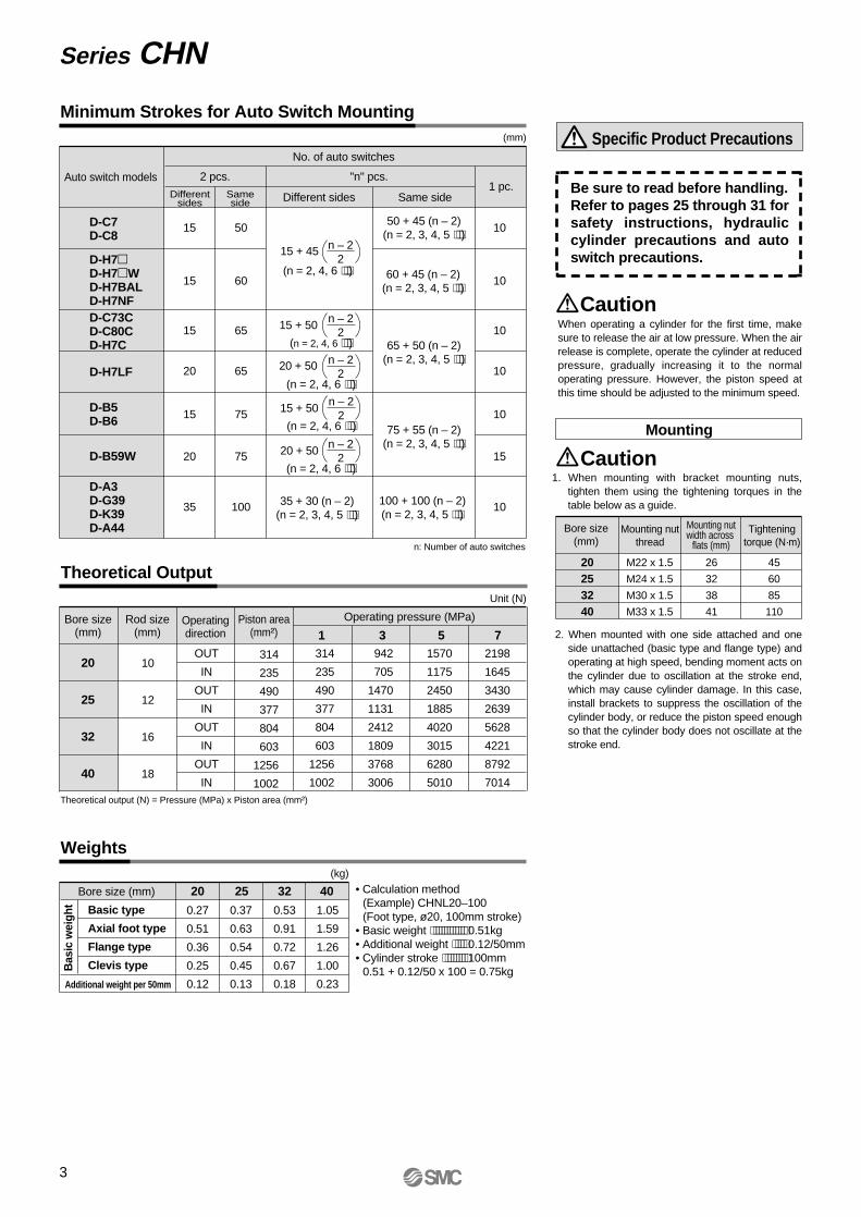
Minimum Strokes for Auto Switch Mounting
Specific Product Precautions
CautionWhen operating a cylinder for the first time, make sure to release the air at low pressure. When the air release is complete, operate the cylinder at reduced pressure, gradually increasing it to the normal operating pressure. However, the piston speed at this time should be adjusted to the minimum speed.
1. When mounting with bracket mounting nuts, tighten them using the tightening torques in the table below as a guide.
2. When mounted with one side attached and one side unattached (basic type and flange type) and operating at high speed, bending moment acts on the cylinder due to oscillation at the stroke end, which may cause cylinder damage. In this case, install brackets to suppress the oscillation of the cylinder body, or reduce the piston speed enough so that the cylinder body does not oscillate at the stroke end.
Theoretical Output
Weights
Bore size (mm) 20 25 32 40
(kg)
0.27
0.51
0.36
0.25
0.12
0.37
0.63
0.54
0.45
0.13
0.53
0.91
0.72
0.67
0.18
1.05
1.59
1.26
1.00
0.23
Bas
ic w
eigh
t Basic type
Axial foot type
Flange type
Clevis type
Additional weight per 50mm
• Calculation method(Example) CHNL20–100(Foot type, ø20, 100mm stroke)
• Basic weight ⋅⋅⋅⋅⋅⋅⋅⋅⋅⋅⋅⋅⋅ 0.51kg• Additional weight ⋅⋅⋅⋅⋅ 0.12/50mm• Cylinder stroke ⋅⋅⋅⋅⋅⋅⋅⋅⋅ 100mm
0.51 + 0.12/50 x 100 = 0.75kg
CautionMounting
Theoretical output (N) = Pressure (MPa) x Piston area (mm²)
Bore size(mm)
Piston area(mm²)
Rod size(mm)
20
25
32
40
10
12
16
18
OUT
IN
OUT
IN
OUT
IN
OUT
IN
314
235
490
377
804
603
1256
1002
1 3 7Operatingdirection
Operating pressure (MPa)
Unit (N)
314
235
490
377
804
603
1256
1002
942
705
1470
1131
2412
1809
3768
3006
2198
1645
3430
2639
5628
4221
8792
7014
51570
1175
2450
1885
4020
3015
6280
5010
Series CHN
Bore size(mm)
20253240
Mounting nutthread
Mounting nutwidth across
flats (mm)
Tighteningtorque (N·m)
M22 x 1.5
M24 x 1.5
M30 x 1.5
M33 x 1.5
45
60
85
110
26
32
38
41
Be sure to read before handling.Refer to pages 25 through 31 for safety instructions, hydraulic cylinder precautions and auto switch precautions.
(mm)
Auto switch models
No. of auto switches
D-C7D-C8
D-H7D-H7WD-H7BALD-H7NF
D-B5D-B6
D-C73CD-C80CD-H7C
D-H7LF
D-B59W
D-A3D-G39D-K39D-A44
15 + 45 n – 22
(n = 2, 4, 6 ⋅⋅⋅)
Differentsides
2 pcs. "n" pcs.
15
15
15
15
20
20
35
Sameside Different sides
50
60
65
75
65
75
100
1 pc.
10
10
10
10
10
15
10
Same side
50 + 45 (n – 2)(n = 2, 3, 4, 5 ⋅⋅⋅)
60 + 45 (n – 2)(n = 2, 3, 4, 5 ⋅⋅⋅)
65 + 50 (n – 2)(n = 2, 3, 4, 5 ⋅⋅⋅)
75 + 55 (n – 2)(n = 2, 3, 4, 5 ⋅⋅⋅)
100 + 100 (n – 2)(n = 2, 3, 4, 5 ⋅⋅⋅)
n: Number of auto switches
15 + 50 n – 22
(n = 2, 4, 6 ⋅⋅⋅)
20 + 50 n – 22
(n = 2, 4, 6 ⋅⋅⋅)
15 + 50 n – 22
(n = 2, 4, 6 ⋅⋅⋅)
20 + 50 n – 22
(n = 2, 4, 6 ⋅⋅⋅)
35 + 30 (n – 2)(n = 2, 3, 4, 5 ⋅⋅⋅)
4
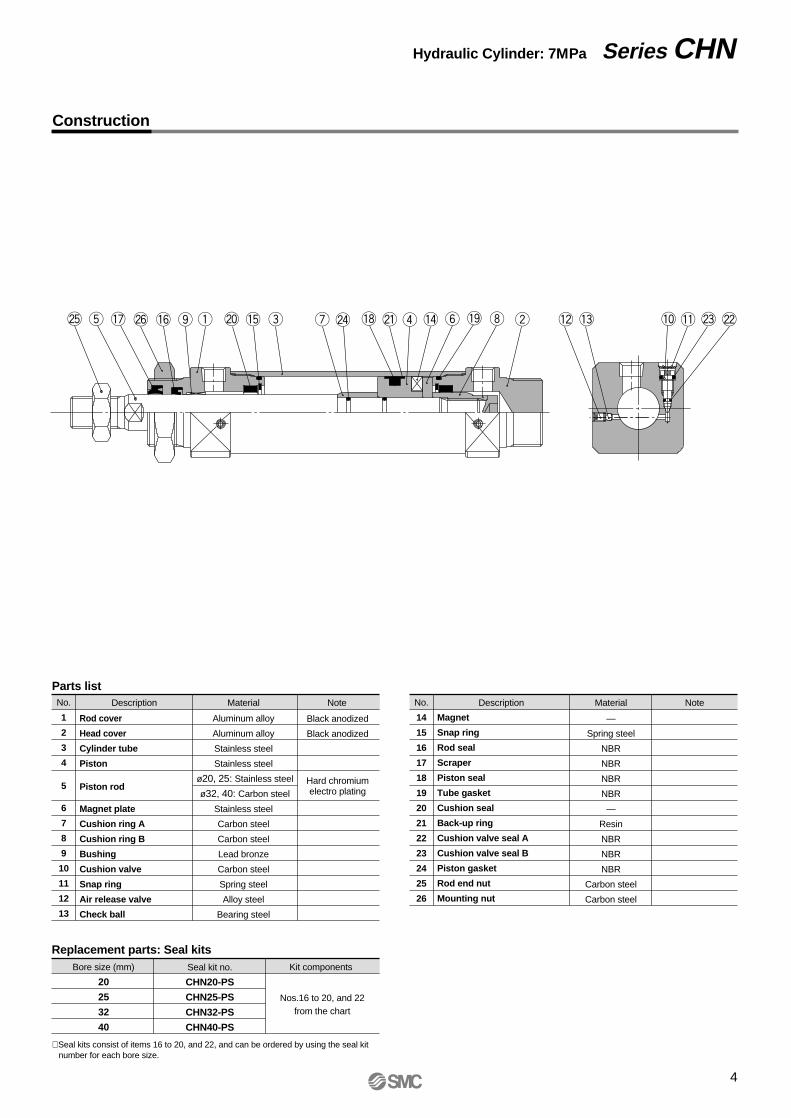
Hydraulic Cylinder: 7MPa Series CHN
Construction
No.
1
2
3
4
5
6
7
8
9
10
11
12
13
Description Material Note
Rod cover
Head cover
Cylinder tube
Piston
Piston rod
Magnet plate
Cushion ring A
Cushion ring B
Bushing
Cushion valve
Snap ring
Air release valve
Check ball
Aluminum alloy
Aluminum alloy
Stainless steel
Stainless steel
Stainless steel
Carbon steel
Carbon steel
Lead bronze
Carbon steel
Spring steel
Alloy steel
Bearing steel
Black anodized
Black anodized
Hard chromiumelectro plating
Parts listNo.
14
15
16
17
18
19
20
21
22
23
24
25
26
Description Material Note
Magnet
Snap ring
Rod seal
Scraper
Piston seal
Tube gasket
Cushion seal
Back-up ring
Cushion valve seal A
Cushion valve seal B
Piston gasket
Rod end nut
Mounting nut
—
Spring steel
NBR
NBR
NBR
NBR
—
Resin
NBR
NBR
NBR
Carbon steel
Carbon steel
Replacement parts: Seal kits
20
25
32
40
Bore size (mm) Seal kit no.
CHN20-PS
CHN25-PS
CHN32-PS
CHN40-PS
Kit components
Nos.16 to 20, and 22from the chart
ø20, 25: Stainless steel
ø32, 40: Carbon steel
@5 t !7 !6@6 o q @0 !5 e u @4 !8 @1 r !4 y !9 i w !2 !3 !0 !1 @3 @2
∗ Seal kits consist of items 16 to 20, and 22, and can be ordered by using the seal kit number for each bore size.
5
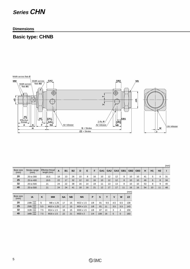
Dimensions
Basic type: CHNB
Bore size(mm)
Stroke range(mm)
25 to 300
25 to 400
25 to 500
25 to 500
Effective threadlength (mm)
15.5
19.5
21
21
20
25
32
40
A
18
22
24
24
B1
13
17
22
24
B2
26
32
38
41
D
10
12
16
18
E
8
10
14
16
F
16
16
19
21
GA1
10
10
11
12
GA2
12
12
13
17
GA3
12
12
13
17
GB1
8
8
8
11
GB3
10
10
10
16
GB2
10
10
10
16
H
41
46
53
54
H1
5
6
8
10
H2
8
8
9
11
I
31
34
40
48
(mm)
øD
TV
øIA
MM GA2 GB2 NN
Air release Air releaseAir release
S + StrokeZZ + Stroke
2-Rc PEffectivethread
Width acrossflats B1
Width acrossflats B2
H1H2 GA1 GB1
W
I
GA33 GB3A K F NA
HNB
Series CHN
Bore size(mm)
20
25
32
40
K
5
5.5
7.5
7.5
MM
M8 x 1.25
M10 x 1.25
M14 x 1.5
M16 x 1.5
NA
17
17
18
22
NB
15
15
15
21
NN
M22 x 1.5
M24 x 1.5
M30 x 1.5
M33 x 2
P
1/8
1/8
1/8
1/4
S
81
81
87
108
T
9.5
11
13
16
W
6.5
5.5
4
0
V
4.5
3.5
3
5
ZZ
138
143
159
183
(mm)
Width across flats E
IA
23f8
25f8
31f8
34f8
-0.020-0.053-0.020-0.053-0.025-0.064-0.025-0.064

6
Axial foot type: CHNL
Bore size(mm)
Stroke range(mm)
25 to 300
25 to 400
25 to 500
25 to 500
Effective threadlength (mm)
15.5
19.5
21
21
20
25
32
40
A
18
22
24
24
B1
13
17
22
24
B2
26
32
38
41
D
10
12
16
18
E
8
10
14
16
F
16
16
19
21
GA1
10
10
11
12
GA2
12
12
13
17
GA3
12
12
13
17
GB1
8
8
8
11
GB3
10
10
10
16
GB2
10
10
10
16
H
41
46
53
54
H1
5
6
8
10
H2
8
8
9
11
I
31
34
40
48
(mm)
K
5
5.5
7.5
7.5
Hydraulic Cylinder: 7MPa Series CHN
Bore size(mm)
20
25
32
40
LH
25
28
30
35
LS
121
121
133
158
LX
40
40
45
55
LZ
55
55
60
75
LT
5.5
5.5
6
6
MM
M8 x 1.25
M10 x 1.25
M14 x 1.5
M16 x 1.5
NA
17
17
18
22
NB
15
15
15
21
P
1/8
1/8
1/8
1/4
S
81
81
87
108
T
9.5
11
13
16
W
6.5
5.5
4
0
X
20
20
23
25
Y
9
9
9
11
V
4.5
3.5
3
5
ZZ
151
156
172
198
(mm)
GA2
GA1
GB2
GB1 TV
LT LH
GA3
Y Y
NA
GB3
NBS + Stroke
LS + Stroke
ZZ + Stroke
X X
F
W
KA
øD
Effectivethread
H
MM
Rc P Rc P Rc P
Air release
Cushion valve Cushion valve
Cushion valve
Air release
4-øLD
I
LX
LZ
LD
7
7
7
9
H1 width across flats B1
Width across flats E
H2 width across flats B2
7
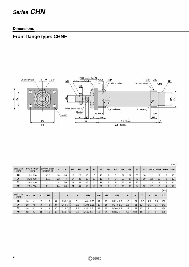
Front flange type: CHNF
Bore size(mm)
Stroke range(mm)
25 to 300
25 to 400
25 to 500
25 to 500
Effective threadlength (mm)
15.5
19.5
21
21
20
25
32
40
A
18
22
24
24
B
38
44
50
60
B1
13
17
22
24
B2
26
32
38
41
D
10
12
16
18
E
8
10
14
16
F
16
16
19
21
FD
7
7
7
9
FT
6
9
9
9
FX
51
53
55
66
FY
21
27
33
36
FZ
68
70
72
84
GA1
10
10
11
12
GA2
12
12
13
17
GA3
12
12
13
17
GB1
8
8
8
11
GB2
10
10
10
16
(mm)
øIA
S + Stroke
Cushion valve
Cushion valve
Cushion valve
ZZ + Stroke
Effectivethread
H1
MM
FT GA3
A K
H
F
Series CHN
NA
GB3
NB
T V
FYB øD
FZ
FX
I
Bore size(mm)
20
25
32
40
K
5
5.5
7.5
7.5
H2
8
8
9
11
I
31
34
40
48
IA
23f8
25f8
31f8
34f8
MM
M8 x 1.25
M10 x 1.25
M14 x 1.5
M16 x 1.5
NA
17
17
18
22
NB
15
15
15
21
NN
M22 x 1.5
M24 x 1.5
M30 x 1.5
M33 x 2
P
1/8
1/8
1/8
1/4
S
81
81
87
108
T
9.5
11
13
16
W
6.5
5.5
4
0
V
4.5
3.5
3
5
ZZ
138
143
159
183
(mm)
3
Width across flats B1H2 GA1
W
GA2
GB1NN
GB2Width across flats B2
Rc PRc P
4-øFD
Rc P
-0.020-0.053-0.020-0.053-0.025-0.064-0.025-0.064
H1
5
6
8
10
Air release Air release
Dimensions
GB3
10
10
10
16
H
41
46
53
54
Width across flats E
8
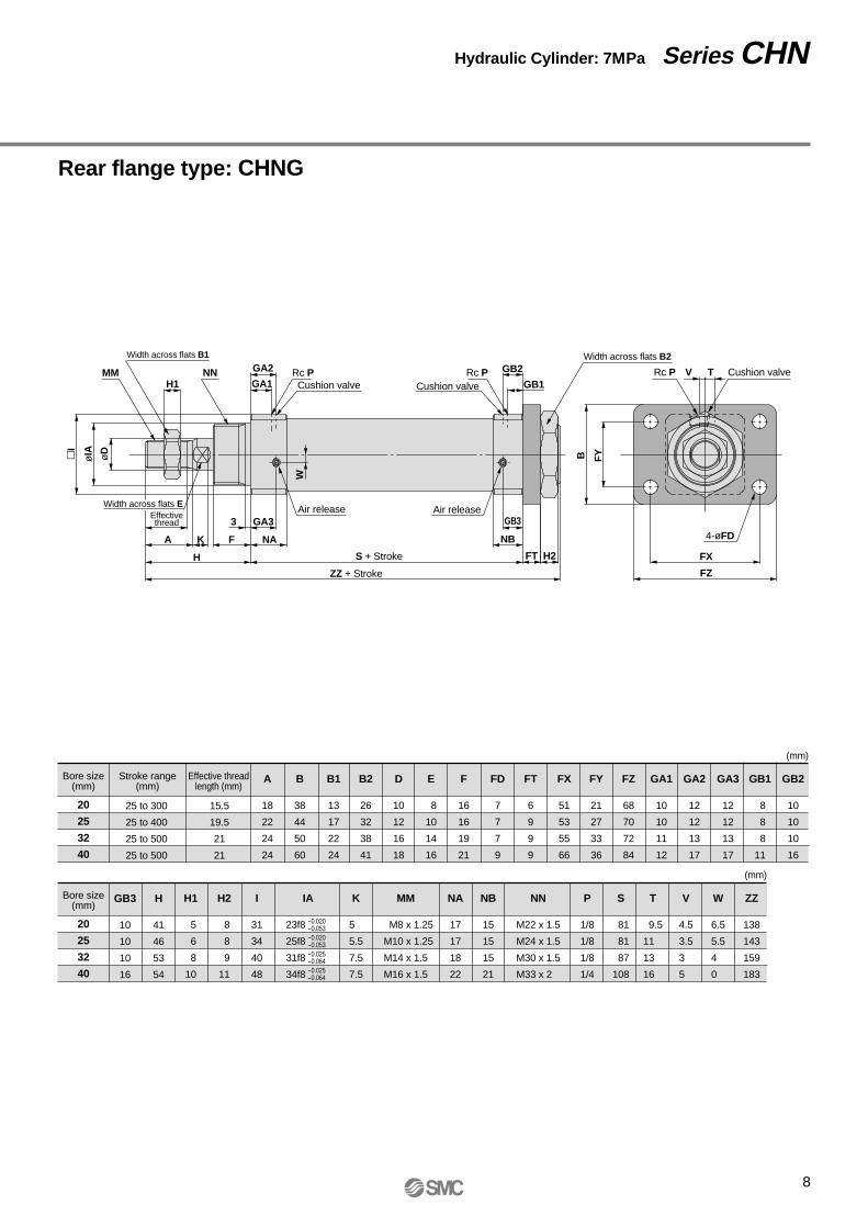
Rear flange type: CHNG
Hydraulic Cylinder: 7MPa Series CHNø
IA øDI
MM
Width across flats B1
Air release Air release
4-øFD
H1 GA1
W
GA2
GB1
GB2NN Rc P Rc P Rc P
Width across flats B2
Cushion valveCushion valve
Cushion valve
FYB
TV
FZ
FX
Effectivethread GA33
A K
H
F NA
S + Stroke
ZZ + Stroke
GB3
NB
FT H2
Bore size(mm)
Stroke range(mm)
25 to 300
25 to 400
25 to 500
25 to 500
Effective threadlength (mm)
15.5
19.5
21
21
20
25
32
40
A
18
22
24
24
B1
13
17
22
24
B2
26
32
38
41
D
10
12
16
18
B
38
44
50
60
E
8
10
14
16
F
16
16
19
21
FD
7
7
7
9
FT
6
9
9
9
FX
51
53
55
66
FY
21
27
33
36
FZ
68
70
72
84
GA1
10
10
11
12
GA2
12
12
13
17
GA3
12
12
13
17
GB1
8
8
8
11
GB2
10
10
10
16
(mm)
Bore size(mm)
20
25
32
40
K
5
5.5
7.5
7.5
H2
8
8
9
11
I
31
34
40
48
IA
23f8
25f8
31f8
34f8
MM
M8 x 1.25
M10 x 1.25
M14 x 1.5
M16 x 1.5
NA
17
17
18
22
NB
15
15
15
21
NN
M22 x 1.5
M24 x 1.5
M30 x 1.5
M33 x 2
P
1/8
1/8
1/8
1/4
S
81
81
87
108
T
9.5
11
13
16
W
6.5
5.5
4
0
V
4.5
3.5
3
5
ZZ
138
143
159
183
(mm)
-0.020-0.053-0.020-0.053-0.025-0.064-0.025-0.064
H1
5
6
8
10
GB3
10
10
10
16
H
41
46
53
54
Width across flats E
9
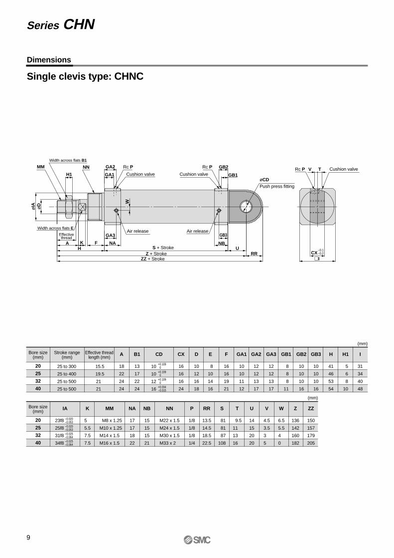
Single clevis type: CHNC
Bore size(mm)
Stroke range(mm)
25 to 300
25 to 400
25 to 500
25 to 500
Effective threadlength (mm)
15.5
19.5
21
21
20
25
32
40
A
18
22
24
24
B1
13
17
22
24
CD CX
16
16
16
24
D
10
12
16
18
E
8
10
14
16
F
16
16
19
21
GA1
10
10
11
12
GA2
12
12
13
17
GA3
12
12
13
17
GB1
8
8
8
11
GB2
10
10
10
16
GB3
10
10
10
16
H1
5
6
8
10
H
41
46
53
54
I
31
34
40
48
(mm)
Series CHN
Bore size(mm)
20
25
32
40
NB
15
15
15
21
K
5
5.5
7.5
7.5
NA
17
17
18
22
IA
23f8
25f8
31f8
34f8
MM
M8 x 1.25
M10 x 1.25
M14 x 1.5
M16 x 1.5
P
1/8
1/8
1/8
1/4
RR
13.5
14.5
18.5
22.5
NN
M22 x 1.5
M24 x 1.5
M30 x 1.5
M33 x 2
S
81
81
87
108
T
9.5
11
13
16
U
14
15
20
20
W
6.5
5.5
4
0
V
4.5
3.5
3
5
ZZ
150
157
179
205
Z
136
142
160
182
(mm)
-0.020-0.053
+0.1090
+0.1090
+0.1090
+0.034-0.015
-0.020-0.053-0.025-0.064-0.025-0.064
H1
MMWidth across flats B1
GA1
GA2NN Rc P
Cushion valve
Air release Air release
Cushion valveCushion valve GB1
GB2Rc P Rc P
øCDPush press fitting
T
I
øIA øD
V
CX
Effectivethread GA3
A KH
F
W
NAS + Stroke
ZZ + StrokeZ + Stroke
GB3
NBU
RR-0.1-0.2
Dimensions
10
10
12
16
Width across flats E
10
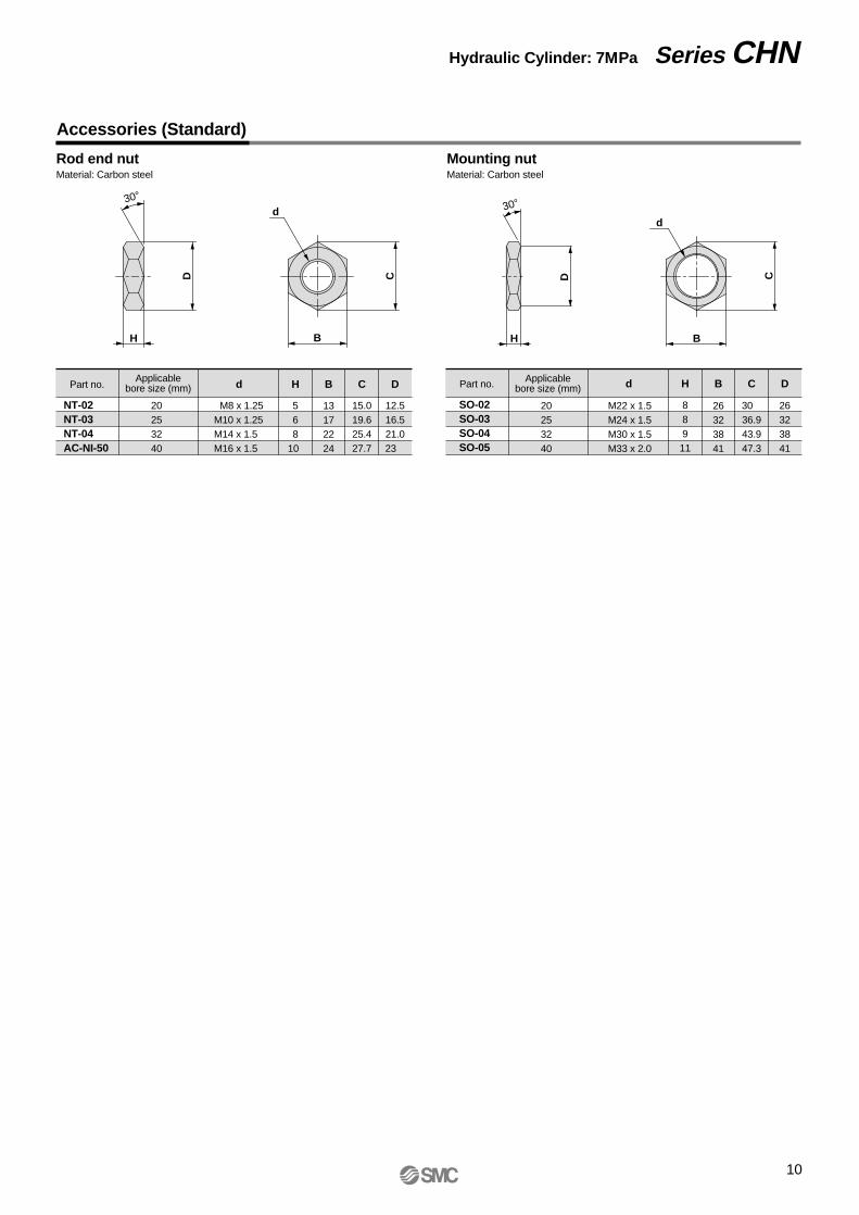
Accessories (Standard)
Rod end nutMaterial: Carbon steel
Mounting nutMaterial: Carbon steel
H B
d
D
H B
D CC
30°30°
Part no. d H B C DApplicablebore size (mm)
NT-02NT-03NT-04AC-NI-50
M8 x 1.25M10 x 1.25M14 x 1.5M16 x 1.5
20253240
568
10
13172224
15.019.625.427.7
12.516.521.023
Part no. d H B C DApplicablebore size (mm)
SO-02SO-03SO-04SO-05
M22 x 1.5M24 x 1.5M30 x 1.5M33 x 2.0
20253240
88911
26323841
3036.943.947.3
26323841
d
Hydraulic Cylinder: 7MPa Series CHN

11
MM
U1U1A1
L1 L1
L tap4-J counter bore
A1
øE
1 øE
1
NX
ø8.
6
ø9d
9-0
.040
-0.0
76
ø12
d9-0
.050
-0.0
93
NZ
NX
øE
1
øE
1
øC
f7
NX
NZ
EF
G
H
I
A B
D+0
.2+0
.1
Accessory Brackets (Optional)
I-shaped single knuckle joint Bracket for clevis typeMaterial: Cast iron
Part no. A1 L1 R1 U1 NDH10 UH8E1 MM NXApplicablebore size
(mm)
Applicablebore size
(mm)
I-02I-03I-04IHN-04
M8 x 1.25M10 x 1.25M14 x 1.5M16 x 1.5
20253240
101015.515.5
16182222
20202424
36385555
14142020
99
1215
99
1616
Part no. HG I J K L
AD-FI-20AD-FI-25AD-FI-32AD-CHN-40
20253240
6.56.51010
5.55.599
M R
5.55.5710
A B C D E F
46465664
60608088
22223030
16161624
10101216
30303644
7779
28304043
10101313
10101212
12121216
M4M4M5M5
+0.0580
-0.1-0.2-0.1-0.2-0.1-0.3-0.1-0.3
+0.0580
+0.0700
+0.0700
+0.027 0 +0.027 0 +0.027 0 +0.027 0
ø20: I-02ø25: I-03Material: Rolled steel plate
ø32: I-04ø40: IHN-04Material: Rolled steel plate
øNDH10
øNDH10RR1
RR1MM
NX
øNDH10øNDH10
RR1 RR1
45°
4-øK
M C
R øUH8
Y-shaped double knuckle joint Bracket pinMaterial: Carbon steel
Part no. A1 L1 R1 U1 NDH10 Cf7E1 MM NX NZApplicablebore size
(mm)Bore size
(mm) Cotter pin
Y-02Y-03Y-04CYHN-04
M8 x 1.25M10 x 1.25M14 x 1.5M16 x 1.5
20253240
12121313
16182222
20202424
36385555
14142525
18183838
99
1215
99
1616
Part no.
AD-EI-20AD-EI-25AD-EI-32AD-CHN-40
20253240
A B D
45.545.55260
35.535.54250
3.23.244
10101216
+0.058 0
+0.2+0.1+0.2+0.1+0.3+0.1+0.3+0.1
+0.058 0 +0.070 0 +0.070 0
-0.016-0.034-0.016-0.034-0.016-0.034-0.016-0.034
ø20: Y-02ø25: Y-03Material: Rolled steel plate
ø32: Y-04Cø40: YHN-04Material: Cast iron
MM
A1 A1 U1
L1
A
B
2-øD drill through
L1
25
19.2 1.75 41.7
49.7
41.75
U1
Knuckle pinø20, ø25Part no.: CDP-1Material: Carbon steel
ø32Part no.: CDP-3Material: Carbon steel
ø3.2 x 16l
ø4 x 20l
C1Chamfer
C1Chamfer
1.15 1.15
2-ø3 drill through
Snap ring: C type 9 for shaft Cotter pin: ø3 x 18l
ø15
d9-0
.050
-0.0
93
41.7
49.7
5
ø40Part no.: CDPN-4Material: Carbon steel
2-ø3.2 drill through
Cotter pin: ø3.2 x 20l
Series CHN
12
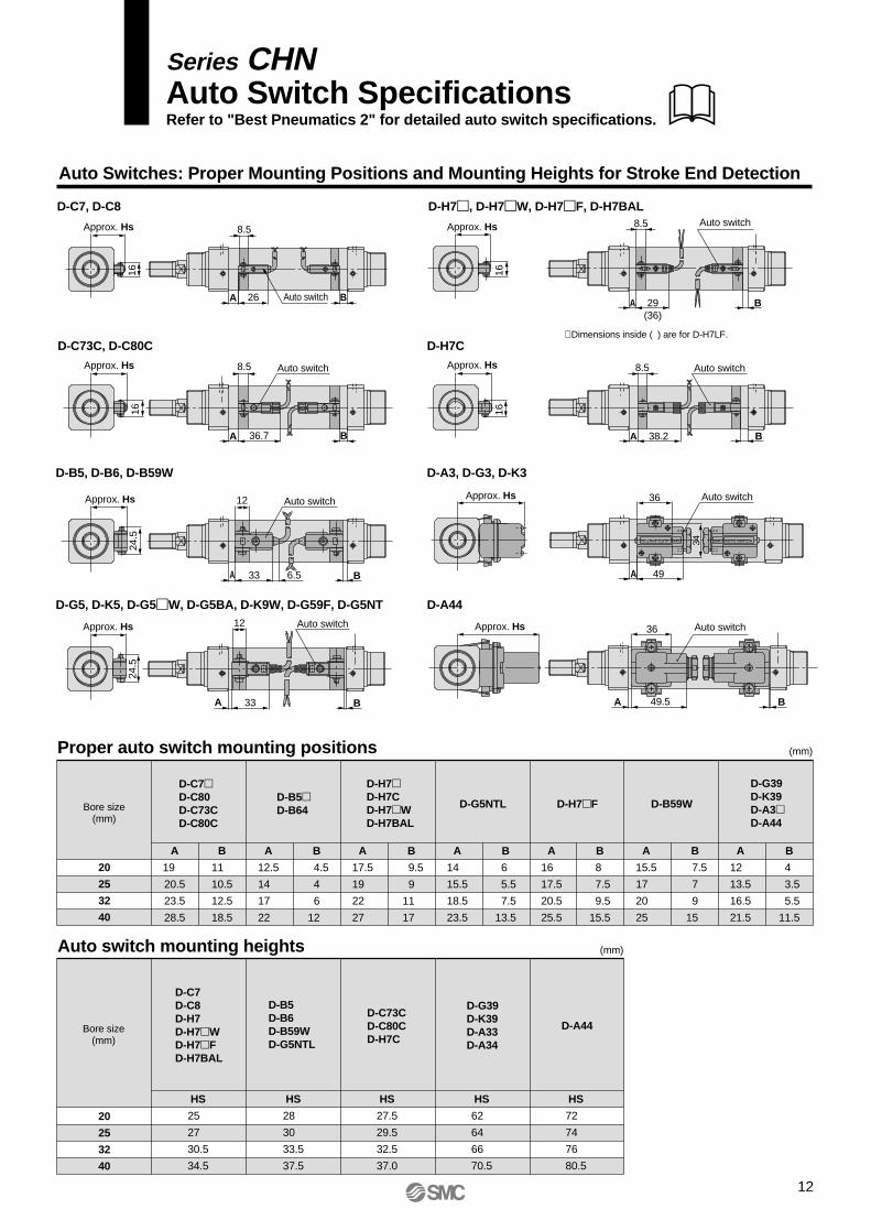
Series CHNAuto Switch SpecificationsRefer to "Best Pneumatics 2" for detailed auto switch specifications.
Auto Switches: Proper Mounting Positions and Mounting Heights for Stroke End Detection
D-C7, D-C8 D-H7, D-H7W, D-H7F, D-H7BAL
D-G5, D-K5, D-G5W, D-G5BA, D-K9W, D-G59F, D-G5NT D-A44
D-C73C, D-C80C D-H7C
D-B5, D-B6, D-B59W D-A3, D-G3, D-K3
20
25
32
40
D-C7D-C80D-C73CD-C80C
D-B5D-B64
D-H7D-H7CD-H7WD-H7BAL
D-H7F D-B59W
D-G39D-K39D-A3D-A44
D-G5NTL
A
19
20.5
23.5
28.5
B
11
10.5
12.5
18.5
A
12.5
14
17
22
B
4.5
4
6
12
A
17.5
19
22
27
B
9.5
9
11
17
A
14
15.5
18.5
23.5
B
6
5.5
7.5
13.5
A
15.5
17
20
25
B
7.5
7
9
15
A
12
13.5
16.5
21.5
B
4
3.5
5.5
11.5
A
16
17.5
20.5
25.5
B
8
7.5
9.5
15.5
Proper auto switch mounting positions
Auto switch mounting heights
Bore size(mm)
20
25
32
40
Bore size(mm)
D-B5D-B6D-B59WD-G5NTL
D-C7D-C8D-H7D-H7WD-H7FD-H7BAL
D-C73CD-C80CD-H7C
D-G39D-K39D-A33D-A34
D-A44
HS
25
27
30.5
34.5
HS
28
30
33.5
37.5
HS
27.5
29.5
32.5
37.0
HS
62
64
66
70.5
HS
72
74
76
80.5
(mm)
(mm)
Approx. Hs
16
Approx. Hs
16
8.5
A 26 BAuto switch
Approx. Hs
16
8.5
A 29(36)
B
Auto switch
Approx. Hs
16
8.5
A 38.2 B
Auto switch
Approx. Hs
Approx. Hs 36
A B49.5
Auto switch
8.5
A 36.7 B
Auto switch
Approx. Hs
24.5
12
A 33 6.5 B
Auto switch
Approx. Hs
24.5
12
A 33 B
Auto switch
∗ Dimensions inside ( ) are for D-H7LF.
36
A 49
Auto switch
34 SMC AUTO SWITCH
SMCAUTO SWITCH
13
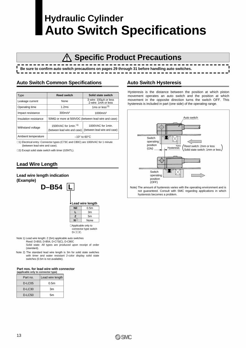
Auto Switch Hysteresis
Specific Product PrecautionsBe sure to confirm auto switch precautions on pages 29 through 31 before handling auto switches.
Auto Switch Common Specifications
Lead Wire Length
Lead wire length indication(Example)
D–B54 L
Lead wire lengthNilLZ
N∗
0.5m3m5m
None
Part nos. for lead wire with connector(applicable only to connector type)
Lead wire length
0.5m
3m
5m
Part no.
D-LC05
D-LC30
D-LC50
Note) The amount of hysteresis varies with the operating environment and is not guaranteed. Consult with SMC regarding applications in which hysteresis becomes a problem.
Switchoperatingposition(OFF)
Switchoperatingposition(ON)
Note)Hysteresis Reed switch: 2mm or less
Solid state switch: 1mm or less
Auto switch
Hydraulic CylinderAuto Switch Specifications
Type
Leakage current
Operating time
Impact resistance
Insulation resistance
Withstand voltage
Ambient temperature
Reed switch
None
1.2ms
300m/s²
Solid state switch
3-wire: 100µA or less2-wire: 1mA or less
1ms or less∗ 2)
1000m/s²
1500VAC for 1min.∗ 1)
(between lead wire and case)
1000VAC for 1min.(between lead wire and case)
–10° to 60°C
50MΩ or more at 500VDC (between lead wire and case)
∗ 1) Electrical entry: Connector types (C73C and C80C) are 1000VAC for 1 minute (between lead wire and case).
∗ 2) Except solid state switch with timer (G5NTL).
∗ Applicable only toconnector type switch D-C.
Note 1) Lead wire length: Z (5m) applicable auto switchesReed: D-B53, D-B54, D-C73(C), D-C80CSolid state: All types are produced upon receipt of order (standard).
Note 2) The standard lead wire length is 3m for solid state switches with timer and water resistant 2-color display solid state switches (0.5m is not available).
Hysteresis is the distance between the position at which piston movement operates an auto switch and the position at which movement in the opposite direction turns the switch OFF. This hysteresis is included in part (one side) of the operating range.

14
Internal circuitsLead wire colors inside [ ] are those prior to conformity with IEC standards.
Part no.Load voltageMaximum load current
Contact Protection Boxes: CD-P11, CD-P12
100VAC25mA
CD-P1224VDC50mA
CD-P11200VAC12.5mA
Contact protection box specifications
Dimensions
Connection
CD-P
VOLT SW
ITC
H
4.4
38
4615.5ø3.4
3.4
9 18
Auto Switch Specifications
<Applicable switch models>D-C7, D-C8, D-C73C, D-C80C
The above auto switches do not have built-in contact protection circuits.
1. The operating load is an induction load.2. The length of wiring to the load is 5m or more 3. The load voltage is 100VAC or 200VAC.A contact protection box should be used in any of the above conditions. Otherwise, the life of the contacts may be reduced. (They may stay on continuously.)
Furthermore, even in the case of a type having an internal contact protection circuit (D-A34, D-A44, D-B54, D-B64, D-B59W), if the length of the wiring to the load is extremely long (30m or more) and a PLC having a large rush current is used, consult with SMC as a contact protection box may be necessary.
Surge absorber
Chokecoil
Chokecoil
Zener diode
CD-P11
CD-P12OUT (+) Brown [Red]
OUT (–) Blue [Black]
OUTBrown [Red]
OUTBlue [Black]
To connect a switch unit to a contact protection box, connect the lead wire from the side of the contact protection box marked SWITCH to the lead wire coming out of the switch unit.
The length of the lead wires between the switch unit and contact protection box should be no more than 1m, and they should be placed as close together as possible.
∗ Lead wire length ––– Switch connection side: 0.5m Load connection side: 0.5m
15
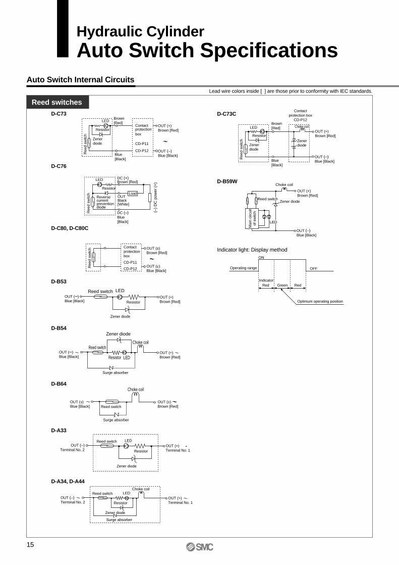
Auto Switch Internal CircuitsLead wire colors inside [ ] are those prior to conformity with IEC standards.
Reed switches
Hydraulic CylinderAuto Switch Specifications
D-C73
D-C76
D-C80, D-C80C
D-B53
D-B54
D-B64
D-A33
D-A34, D-A44
LED
Ree
d sw
itch
Resistor
Zenerdiode
Contactprotectionbox
CD-P11
CD-P12
Brown[Red]
Blue[Black]
OUT (+) Brown [Red]
OUT (–) Blue [Black
LED
Ree
d sw
itch
Resistor
Reversecurrent preventiondiode
OUTBlack[White]
DC (+)Brown [Red]
DC (–)Blue[Black]
Load
(–)
DC
pow
er (
+)
Ree
d sw
itch Contact
protection box
CD-P11
CD-P12
OUT (±) Brown [Red]
OUT ( ) Blue [Black]
Zener diode
Reed switch LED
Resistor
OUT (–)Blue [Black]
OUT (+)Brown [Red]
Zener diode
Reed switch
LEDResistor
Choke coil
Surge absorber
OUT (–)Blue [Black]
OUT (+) Brown [Red]
Reed switch
Choke coil
Surge absorber
OUT (±) Brown [Red]
OUT ( ) Blue [Black]
±
Zener diode
Reed switch LED
Resistor
OUT (–)Terminal No. 2
OUT (+) Terminal No. 1
Zener diode
Reed switch LED
Resistor
Choke coil
Surge absorber
OUT (+) Terminal No. 1
OUT (–) Terminal No. 2
±
D-C73C
Blue[Black]
LED
Ree
d sw
itch
Resistor
Zenerdiode
Brown[Red]
OUT (–) Blue [Black]
OUT (+) Brown [Red]
Choke coil
Contactprotection box
CD-P12
Zener diode
D-B59W
Indicator light: Display method
Choke coil
Zener diode
Mai
n ci
rcui
tof
sw
itch
Reed switch
LED
OUT (+) Brown [Red]
OUT (–) Blue [Black]
Optimum operating position
Operating range OFF
ON
RedIndicator
Green Red

Solid state switches
16
Lead wire colors inside [ ] are those prior to conformity with IEC standards.
Auto Switch Specifications
D-H7A1
D-G39, D-G39C
D-H7A2
D-H7B, D-H7C
D-K39, D-K39C
OUTBlack [White]
DC (+)Brown [Red]
DC (–)Blue [Black]
Mai
n ci
rcui
tof
sw
itch
OUTTerminal No. 2
DC (+)Terminal No. 1
DC (–)Terminal No. 3
Mai
n ci
rcui
tof
sw
itch
Mai
n ci
rcui
tof
sw
itch
Mai
n ci
rcui
tof
sw
itch
Mai
n ci
rcui
tof
sw
itch
OUTBlack [White]
DC (+)Brown [Red]
DC (–)Blue [Black]
OUT (+)Brown [Red]
OUT (–)Blue [Black]
OUT (+)Terminal No. 1
OUT (–)Terminal No. 2
D-H7PW
D-H7BAL, D-H7BW
Mai
n ci
rcui
tof
sw
itch
OUTBlack [White]
DC (+)Brown [Red]
DC (–)Blue [Black]
Mai
n ci
rcui
tof
sw
itch
OUT (+)Brown [Red]
OUT (–)Blue [Black]
D-H7NW
D-H7NF
D-G5NTL
Diagnosis OUT(diagnostic output)Orange [Yellow]
Mai
n ci
rcui
tof
sw
itch
Mai
n ci
rcui
tof
sw
itch
Mai
n ci
rcui
tof
sw
itch
OUTBlack [White]
DC (+)Brown [Red]
DC (–)Blue [Black]
OUT (normal output)Black [White]
DC (+)Brown [Red]
DC (–)Blue [Black]
OUTBlack [White]
DC (+)Brown [Red]
DC (–)Blue [Black]
D-H7LF
Diagnosis OUT(diagnostic output)Orange [Blue]
Mai
n ci
rcui
tof
sw
itch
OUT (normal output)Black [White]
DC (+)Brown [Red]
DC (–)Blue [Black]

17
Hydraulic CylinderAuto Switch Connections and Examples
Basic Wiring
Solid state 3-wire, NPN
Sink input specifications
Solid state 2-wire
Source input specifications
2-wire with 2-switch AND connection 2-wire with 2-switch OR connection
2-wire 2-wire
Solid state 3-wire, PNP
Example: Power supply is 24VDC. Internal voltage drop in switch is 4V.
Example: Load impedance is 3kΩ.Leakage current from switch is 1mA.
(Power supplies for switch and load are separate.)
Connection Examples for AND (Series) and OR (Parallel)
Examples of Connection to PLC
The connection method will vary depending on the PLC input specifications. Connect accordingly.
When 2 switches are con-nected in series, the load may malfunction because the load voltage will decline when in the ON state.The indicator lights will light up when both of the switches are in the ON state.
<Solid state>When 2 switches are connected in parallel, malfunction may occur because the load voltage will increase when in the OFF state.
Blue[Black]
Maincircuit
of switchLoad
Brown [Red]
Black[White]
Maincircuit
of switch
Brown[Red]
Load
Blue[Black]
Black[White]
Maincircuit
of switch
LoadBlue[Black]
Brown[Red]
Maincircuit
of switch
Load
Blue[Black]
Brown[Red]
Maincircuit
of switch
Load
Brown[Red]
Blue[Black]
Black[White]
PLC internal circuitCOM
Switch
InputBlack[White]
Brown[Red]
Blue[Black]
PLC internal circuitCOM
Switch
InputBrown[Red]
Blue[Black] PLC internal circuit
Switch
Input
COM
Blue[Black]
Brown[Red]
PLC internal circuitCOM
Switch
InputBlack[White]
Brown[Red]
Blue[Black]
Switch 1
Switch 2
Load
Blue[Black]
Brown[Red]
Blue[Black]
Brown[Red]
Switch 1
Switch 2
Load
Brown[Red]
Blue[Black]
Brown[Red]
Blue[Black]
3-wireOR connection for NPN output
Switch 1
Switch 2
LoadSwitch 1
Brown[Red]
Switch 2
Black[White]
Blue[Black]
Relay
RelayBlack[White]
Load
Relaycontact
AND connection for NPN output(using relays)
Switch 1
Brown[Red]
Switch 2
Load
Brown[Red]
AND connection for NPN output(performed with switches only)
The indicator lights will light up when both switches are turned ON.
<Reed switch>
Reed switch 2-wire
Indicatorlight,
protectioncircuit,
etc.
Brown[Red]
Blue[Black]
Load
Brown[Red]
Blue[Black]
Load
3-wire, NPN 3-wire, PNP
Brown [Red]
Blue[Black]
Blue[Black]
Black[White]
Black[White]
Blue[Black]
Brown[Red]
Blue[Black]
Black[White]
Blue[Black]
Black[White]
Brown[Red]
Because there is no current leakage, the load voltage will not increase when turned OFF. However, depending on the number of switches in the ON state, the indicator lights may sometimes grow dim or not light up because of the dispersion and reduction of current flowing to the switches.
Indicatorlight,
protectioncircuit,
etc.
Load voltage at ON = – x 2 pcs.
= 24V – 4V x 2 pcs. = 16V
Power supply voltage
Residual voltage
Leakagecurrent
LoadimpedanceLoad voltage at OFF = x 2 pcs. x
= 1mA x 2 pcs. x 3kΩ= 6V

18
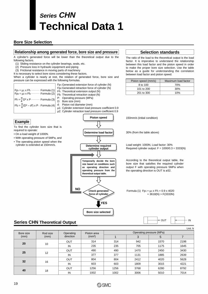
Bore Size Selection
Relationship among generated force, bore size and pressure
19
Series CHN
Technical Data 1
Example
Selection standards
Piston speed (mm/s)8 to 100
101 to 200201 to 300
Maximum load factor70%30%10%
Series CHN Theoretical Output
Bore size(mm)
Rod size(mm)
Piston area(mm²)
OUT
IN
OUT
IN
OUT
IN
OUT
IN
20
25
32
40
10
12
16
18
314
235
490
377
804
603
1256
1002
1314
235
490
377
804
603
1256
1002
3942
705
1470
1131
2412
1809
3768
3006
51570
1175
2450
1885
4020
3015
6280
5010
72198
1645
3430
2639
5628
4221
8792
7014
Operating pressure (MPa)
Unit: N
OUT IN
Check generatedforce of cylinder
Piston speed
Bore size selected
Determine load factor
Determine requiredcylinder output
150mm/s (initial condition)
30% (from the table above)
Load weight: 1000N, Load factor: 30%Required cylinder output: F = 1000/0.3 = 3333(N)
Formula (1) Fp1 = µ1 x Ff1 = 0.9 x 4020= 3618(N) > F(3333N)
NO
YES
Fp₁:Generated extension force of cylinder (N) Fp₂:Generated retraction force of cylinder (N) Ff₁: Theoretical extension output (N) Ff₂: Theoretical retraction output (N) P: Operating pressure (MPa) D: Bore size (mm) d: Piston rod diameter (mm) µ1: Cylinder extension load pressure coefficient 0.9µ2: Cylinder retraction load pressure coefficient 0.9
Fp₁ = µ1 x Ff₁Fp₂ = µ2 x Ff₂
Ff₁ = D² x P
Ff₂ = (D² – d²) x P
Formula (1)Formula (2)
Formula (3)
Formula (4)
π4π4
A cylinder's generated force will be lower than the theoretical output due to the following factors.
(1) Sliding resistance on the cylinder bearings, seals, etc.(2) Pressure loss in hydraulic equipment and piping(3) Frictional resistance in moving parts of machinery
It is necessary to select bore sizes considering these factors.When a cylinder is nearly at rest, the relation of generated force, bore size and pressure can be expressed with the following formulas.
The ratio of the load to the theoretical output is the load factor. It is imperative to understand the relationship between this load factor and the piston speed in order to make the proper bore size selection. Use the table below as a guide for understanding the correlation between load factor and piston speed.
To find the cylinder bore size that is required to operate:• On a load weight of 1000N.• With operating pressure of 5MPa, and• The operating piston speed when the
cylinder is extended at 150mm/s.
Temporarily decide the bore size based on conditions such as operating direction and operating pressure from the theoretical output table.
According to the theoretical output table, the bore size that satisfies the required cylinder output F with operating pressure 5MPa when the operating direction is OUT is ø32.
Operatingdirection

Series CHN
Technical Data 2Stroke Selection (Maximum Usable Stroke Based on Buckling Strength)
Series CHN Stroke range limit charts: Bore size ø20, ø25, ø32, ø40
Symbol
q
r
u
t
u
e
t
i
e
y
Mounting orientation Symbol Mounting orientation Symbol Mounting orientation Symbol Mounting orientation
20
Bore size ø20 Bore size ø25
Load (kN) Load (kN)
Str
oke
(mm
)
800
500
100
500.05 0.1 0.5 1 2 0.05 0.1 0.5 1 2
F
F
F
F F
F F
F
F
F
6 4
1 58 3 7 6 5 4 8 3 71
Load (kN) Load (kN)
Str
oke
(mm
)
800
500
100
500.05 0.1 0.5 1 2 3 0.1 0.05 0.5 1 2 5
6 8 6 4 8 3 75
1
3 74
5
1
Bore size ø32 Bore size ø40
Refer to stroke range limit charts regarding rod buckling due to load weight.The values in these tables indicate the maximum stroke that can be used in a situation when air is being supplied while the cylinder is stopped in an intermediate position by a) an external force acting on
the piston rod and/or b) by an external stopper.Since the maximum usable stroke varies depending on the diameter of the piston rod and operating conditions, verify the applicability using the stroke range limit charts.

Cylinder Cushion Selection
Procedure
21
Series CHN
Technical Data 3-1
Calculation Example
<Design conditions>Cylinder: CHN25Set pressure P1: 5MPaLoad weight M: 50kgPiston speed V: 0.3m/s (at the cushion seal contact point)Load transfer direction: Downward θ: 30°
(External force applied to the cylinder is gravity only).Operating direction: OutGravitational acceleration g: 9.8m/s²
Install a shock absorber
ConfirmE1 + E2 ≤ E
Lower theset pressure
Use largerbore size
Available for use
YES
YESYESYES
Reduceinertial load
NO
NO NO NO
Caution
30°Mg
Mg sin θθ
<Calculation>1. Load inertial energy E1 at the cushion seal
contact pointE1 = MV²/2 = 50 x 0.3²/2 = 2.25J
2. External force F applied in axial direction of the cylinder at the cushion seal contact pointF = Mg sin θ = 50 x 9.8 x sin 30° = 245N
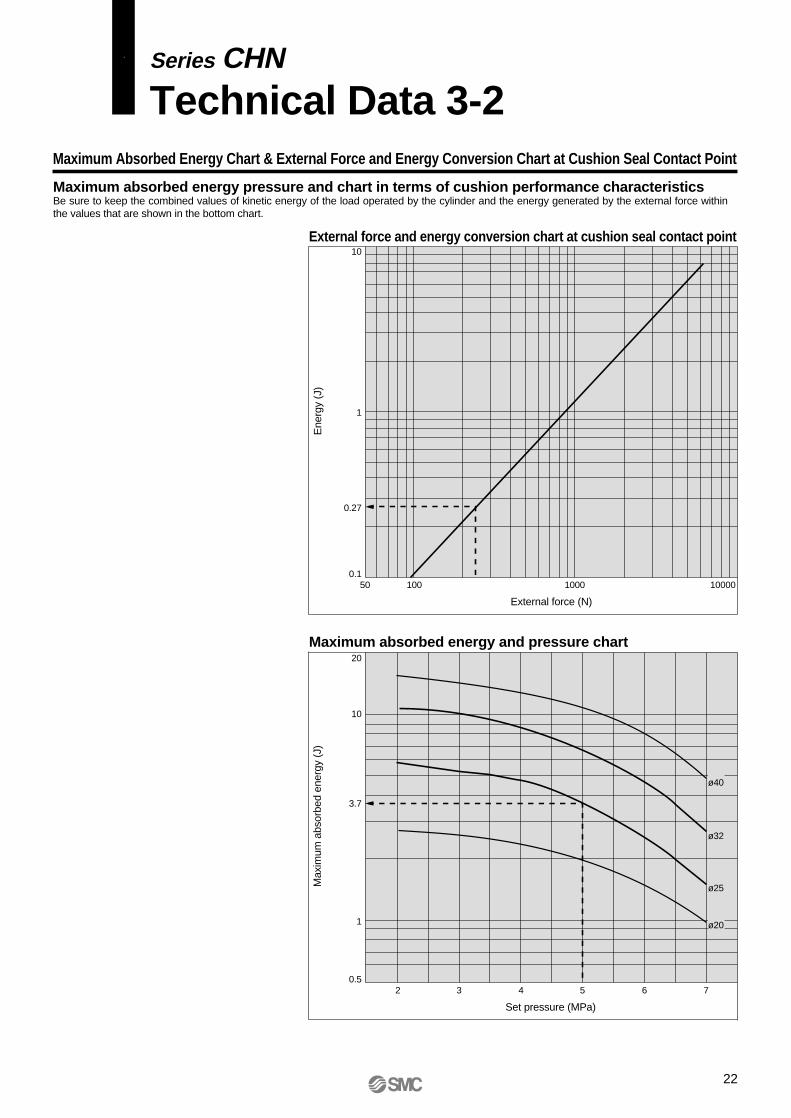
3. Convert the external force calculated in step 2 into energy E2.In the "External force and energy conversion chart" on page 22, draw a vertical line from the value of F (= 245N). The point where this line intersects with the diagonal line (0.27J) is the energy caused by external force.
E2 = 0.27J
4. Find the maximum absorbed energy E for a cylinder.In the "Maximum absorbed energy and pressure chart" on page 22, draw a vertical line from the set pressure 5MPa. The point where this line intersects with the line for ø25 (3.7J) is the maximum absorbed energy.
E = 3.7J
5. Confirm that E1 + E2 ≤ EE1 + E2 = 2.25 + 0.27 = 2.52JSince E = 3.7J, E1 + E2 ≤ ETherefore, the cylinder cushion is available for use.
Convert the external force calculated in step 2 above into energy E2 using the external force energy conversion chart.
From the maximum absorbed energy-pressure chart, find the maximum absorbed energy E for the corresponding cylinder.
Use a cylinder cushion within the maximum absorbed energy range.When used outside the allowable range, it may cause damage to cylinders and peripheral devices.Find the inertial energy E1 for
the load at the cushion seal contact point.
Find the external force F applied in the axial direction of the cylinder at the cushion seal contact point.
Series CHN
Technical Data 3-2Maximum Absorbed Energy Chart & External Force and Energy Conversion Chart at Cushion Seal Contact Point
Maximum absorbed energy and pressure chart
Set pressure (MPa)
Max
imum
abs
orbe
d en
ergy
(J)
ø40
ø25
ø20
ø32
2 3 4 5 6 70.5
1
3.7
10
20
22
Ene
rgy
(J)
External force and energy conversion chart at cushion seal contact point
External force (N)
50 100 1000 100000.1
0.27
1
10
Maximum absorbed energy pressure and chart in terms of cushion performance characteristicsBe sure to keep the combined values of kinetic energy of the load operated by the cylinder and the energy generated by the external force within the values that are shown in the bottom chart.

23
ø4 (steel pipe I.D.)
Flow velocity inside pipe (m/s) Piston speed (mm/s)
30
20
12
109
8
7
6
5(approx. 4.5)
4
3
2
Flo
w r
ate
(l/m
in)
7 6 5 4 3 2 20 30 40 50 60 80 100 200 3002.8
ø5
ø7
ø8
3/8" (ø9.5) rubber hose
ø9
ø12 rubber hose
ø10 ø13
ø15
ø17
1/2" (ø12.7 ) rubber hose 5/8" (ø15.3) rubber hose
3/4" (ø19) rubber hose
ø61/4" (ø6.3) rubber hose
Piston Speed, Required Fluid Volume, and Piping Size Selection
Relationship between piston speedand fluid volume
Effective inside diameter of piping
Rubber hose
Steel piping
5m/s
4.5m/s
Fluid flow velocity
Series CHN
Technical Data 4
General range of rubber hose (max. 5m/s)
General range of steel pipe (max. 4.5m/s)
Q₁ = D²⋅ υ⋅π__4
6_____1000
Q₂ = (D² – d²) ⋅ υ ⋅π__4
6_____1000
…………… Formula (1)
.…… Formula (2)
……… Formula (3)din² x 10-₃π__
4
V = ⋅Q 1___60
: Fluid flow velocity (m/s): Fluid volume (l/min): Effective inside diameter of piping (mm)
VQdin
: Required fluid volume for extension (l/min): Required fluid volume for retraction (l/min): Bore size (cm): Piston rod diameter (cm): Piston speed (mm/s)
Q₁
Q₂
Ddυ
In general, it is necessary to select a piping diameter that will not allow the fluid flow velocity to exceed the values shown in the chart below.If the fluid flow velocity exceeds this value, turbulent flow and overheating may occur in conjunction with pressure loss.
How to read the chart: Example) The required flow rate to operate a ø40 cylinder at a speed of 60mm/s is approximately 4.5l/min.
When a ø6 (I.D.) steel pipe is used for piping, the flow velocity in the piping will be approximately 2.7m/s.
This information is intended to help you find the required fluid volume and piping size to operate a cylinder at a specified speed.
Cyl
inde
r bor
e si
ze ø
40
Cyl
inde
r bor
e si
ze ø
32
Cyl
inde
r bor
e si
ze ø
25
Cyl
inde
r bor
e si
ze ø
20

24
Series CHN
Safety Instructions
Note 1) ISO 4413: Hydraulic fluid power — General rules for the application of equipment to transmission and control systems
Note 2) JIS B 8361: General Rules for Hydraulic Equipment
Warning
Caution : Operator error could result in injury or equipment damage.
Warning : Operator error could result in serious injury or loss of life.
Danger : In extreme conditions, there is a possible result of serious injury or loss of life.
These safety instructions are intended to prevent a hazardous situation and/or equipment damage. These instructions indicate the level of potential hazard by a label of "Caution", "Warning", or "Danger". To ensure safety, be sure to observe ISO 4413 Note 1), JIS B 8361 Note 2) and other safety practices.
1. The compatibility of hydraulic cylinders is the responsibility of the person who designs the hydraulic system or decides its specifications.Since the products specified here are used in various operating conditions, their compatibility with the specific hydraulic system must be based on specifications or after analysis and/or tests to meet your specific requirements.
2. Only trained personnel should operate hydraulic machinery and equipment.Oil hydraulics can be dangerous if an operator is unfamiliar with it. Assembly, handling, or repair of hydraulic systems should be performed by trained and experienced operators.
3. Do not service machinery/equipment or attempt to remove components until safety is confirmed.1. Inspection and maintenance of machinery/equipment should only be performed after confirmation of
safe locked-out control positions.2. When equipment is to be removed, confirm the safety process as mentioned above. Cut the oil supply
pressure and electric power for this equipment and confirm that there is no pressure in the system.3. Before machinery/equipment is restarted, take measures to prevent shooting-out of cylinder piston
rod, etc., and proceed with caution.
4. Contact SMC if the product is to be used in any of the following conditions:1. Conditions and environments beyond the given specifications, or if product is used outdoors.2. Installation on equipment in conjunction with atomic energy, railway, air navigation, vehicles, medical
equipment, food and beverages, recreation equipment, emergency stop circuits, press applications, or safety equipment.
3. An application which has the possibility of having negative effects on people, property, or animals, and therefore requires special safety analysis.
25

Series CHNHydraulic Cylinder Precautions 1Be sure to read before handling.
1. There is a danger of sudden erratic action by air cylinders if sliding parts of machinery are twisted, causing changes in forces to occur.In such cases, human injury may occur, e.g., by catching hands or feet in the machinery, or damage to the machinery itself may occur. Therefore, the machine should be adjusted to operate smoothly and designed to prevent such dangers.
2. A protective cover is recommended to minimize the risk of personal injury.If driven objects and moving parts of a cylinder pose a likely threat of personal injury, design the structure to avoid direct human contact with that area.
3. Securely tighten all of the cylinder's stationary parts and connected parts so that they will not become loose.Especially when a cylinder operates with high frequency or is installed where there is a lot of vibration, ensure tightening so that all parts remain secure.
4. Cases when a deceleration circuit or shock absorber may be requiredWhen a driven object is operated at high speed or the load is heavy, a cylinder's cushion will most likely not be sufficient to absorb the impact. Install a deceleration circuit to reduce the speed before cushioning, or install an external shock absorber to relieve the impact. In this case, the rigidity of the machinery should also be examined.
5. Take into account a possible drop in circuit pressure due to a power outage.When the cylinder is used as a clamping mechanism, there is a danger of work pieces dropping out of it if there is a decrease in clamping force due to a drop in circuit pressure caused by a power outage. Therefore, safety equipment should be installed to prevent damage to machinery and human injury. Also apply drop prevention measures to suspension mechanisms and lifting devices.
6. Take into account a possible loss of power supply.Measures should be taken to protect against human injury and equipment damage in the event that there is a loss of power to equipment controlled by air pressure, electricity, or hydraulics.
7. Design circuitry to prevent sudden lurching of driven objects.When hydraulic pressure in a cylinder is zero, the driven object will lurch at high speed if pressure is applied to one side of the piston. Therefore, equipment should be selected and circuits designed to prevent sudden lurching because there is a danger of human injury and/or damage to equipment when this occurs.
8. Take into account emergency stops.Design the system so that human injury and/or damage to machinery and equipment will not occur when machinery is stopped by a manual emergency stop or a safety device triggered by abnormal conditions such as a power outage.
1. Confirm the specifications.The products featured in this catalog are designed strictly for use in industrial oil hydraulic system applications. If the products are used in conditions that are outside the range of pressure and temperature specifications, damage and/or malfunction may occur. Do not use in these conditions. (Refer to specifications.)Consult with SMC if a fluid other than hydraulic fluid is to be used.
2. Intermediate stopsSince hydraulic cylinders are not guaranteed for zero oil leakage, it may not be possible to hold a stopped position for an extended period of time.
3. Take surge pressure into consideration.Use cylinders which can withstand the surge pressures (maximum allowable pressure) generated in hydraulic systems. (Refer to specifications.)Inside cylinders, pressure may be generated that is higher than the set pressure for the relief valve, e.g., internal pressure due to load inertia or surge pressure when switching valves.Consider these factors and determine the operating pressure so that the pressure generated inside cylinders will be within the maximum allowable pressure.Pressure terminology used in this catalog is defined as follows:Nominal pressure: Pressure assigned to a cylinder for convenient identification. It is not necessarily the same as the operating pressure which guarantees performance under specified conditions.Maximum allowable pressure: The maximum allowable value for the pressure that is generated inside cylinders (such as surge pressure).Proof pressure: Test pressure that the cylinder must be able to withstand without lowering system performance when returning to the nominal pressure.Minimum operating pressure: Minimum pressure at which a horizontally installed cylinder operates with no-load.
4. Take into account compatibility with hydraulic fluids.
Selection
Design
Warning
Warning
Hydraulic fluid Compatibility
Compatible
Compatible
Compatible
∗Not compatible
∗ Consult with SMC.
Standard mineral hydraulic fluid
W/O hydraulic fluids
O/W hydraulic fluids
Water/Glycol hydraulic fluids
Phosphate hydraulic fluids
Design
Warning9. Consider the action of the system when
operation is restarted after an emergency stop or abnormal stop.Design machinery so that human injury or equipment damage will not occur upon restart of operation. In the case that the cylinder needs to be reset at the starting position, install safe manual control equipment.
26

1. Operate within the limits of the maximum stroke.The piston rod will be damaged if operated beyond the maximum stroke. Refer to the stroke selection on page 20 for maximum strokes.
2. Operate the piston within a range that will prevent impact damage from occuring at the stroke end.Ensure a safety margin so that damage will not occur when the piston, having inertial force, stops by striking the cover at the stroke end. Take load factors and piston speed on page 19 into consideration and determine the operability by referring to the chart under "Selection Standards".
3. Use a flow control valve to adjust the hydraulic cylinder drive speed, gradually increasing from a low speed to the desired speed setting.
4. Provide intermediate supports for long stroke cylinders.Provide intermediate supports for cylinders with long strokes to prevent piston rod damage due to sagging of the piston rod, deflection of the tube, vibration, and external loads.
Caution
Selection
Series CHNHydraulic Cylinder Precautions 2Be sure to read before handling.
Mounting
Caution1. Make sure to align the axis center of the
piston with the load and direction of movement when connecting.When not properly aligned, twisting of the piston rod and tubing may occur, and damage may be caused due to wear on areas such as the inner tube surface, bushings, piston rod surface and seals.Allow for decentering of the axis either by aligning the axis center or using a floating joint.
2. When an external guide is used, connect the piston rod end and the load in such a way that there is no interference at any point within the stroke.
3. Do not scratch or gouge the sliding parts of the cylinder tube by striking or grasping it with other objects.Cylinder bores are manufactured to precise tolerances, so that even a slight deformation may cause faulty operation.
4. Do not use until you can verify that equip-ment can operate properly.Following mounting, repairs, or conversions, verify correct mounting by conducting suitable function and leakage tests after piping and power connections have been made.
5. Instruction manualThe product should be mounted and operated only after thoroughly reading the manual and understanding its contents.Keep the instruction manual readily available for easy reference as needed.
1. Preparation before pipingBefore piping is connected, it should be thoroughly flushed out with air or water to remove chips, cutting oil and other debris.
2. Wrapping of sealant tapeWhen screwing together pipes and fittings, be certain that chips from the pipe threads and sealing material do not get inside the piping.Also, when sealant tape is used, leave 1.5 to 2 thread ridges exposed at the end of the threads.
Piping
Caution
3. Set up so that air cannot accumulate inside piping.
Wrapping direction
Sealant tape
Expose approx. 2 threads
27
1. Readjust using the cushion needle.Cushions are adjusted at the time of shipment. However, the cushion needle on the cover should be readjusted when the product is put into service, based on factors such as the size of the load and the operating speed. When the cushion needle is turned clockwise, the restriction becomes smaller and the cushion's effectiveness is increased.
2. Do not operate with the cushion needle fully closed.This will contribute to the generation of surge pressure, and the cylinder or equipment can be damaged.
Cushion
Caution
1. Operate after opening the air release valve and completely releasing any internal air.Residual air can cause a malfunction.
2. When adjusting the air release, do not loosen the plug too much.Use caution, since loosening the plug too much may cause it to fly out or fluid to blow out, posing a danger of human injury.
Air Release
Caution

1. Install hydraulic fluid filters.Provide your hydraulic system with hydraulic fluid filters with a filtration degree of 10mm or finer.Refer to SMC's hydraulic filter specifications.
2. Use the product within the specified range of fluid and ambient temperature.Take measures to prevent freezing, since moisture in hydraulic fluid will freeze at 0°C or below, and this may cause damage to seals and lead to a malfunction.
3. Use hydraulic fluid with a viscosity grade equivalent to ISO VG32 or VG46.
Caution
1. Use clean fluid.Do not use deteriorated fluid or fluid containing foreign matter, moisture or corrosive additives, as this can cause the malfunction and damage or corrosion of parts.
Hydraulic Fluid
Warning
Series CHNHydraulic Cylinder Precautions 3Be sure to read before handling.
Operating Environment
Warning1. Do not use in environments where there is a
danger of corrosion.Refer to the construction drawings for cylinder materials.
2. Install a protective cover if the product is to be used in a dusty environment or where it will be exposed to chips and spatter.
1. Perform maintenance according to the proce-dures indicated in the instruction manual.Improper handling and maintenance may cause malfunctioning and damage of machinery or equipment to occur.
2. Removal of equipmentWhen machinery is removed, first ensure that there are measures in place to prevent the fall or sudden, erratic movement of driven objects and equipment. Then cut off the air supply and electric power, and reduce the pressure in the system to zero.When machinery is restarted, proceed with caution after confirming measures to prevent cylinder lurching.
1. Perform periodic maintenance on filters installed in a hydraulic system in order to keep the fluid clean.If the fluid used in hydraulic cylinders contains foreign matter, parts such as the piston seals and rod seals will be damaged.
Maintenance
Warning
Caution
28

Series CHNAuto Switch Precautions 1Be sure to read before handling.
Warning
Design and Selection
1. Confirm the specifications.Read the specifications carefully and use this product appropriately. The product may be damaged or malfunction if it is used outside the range of specifications for current load, voltage, temperature, or impact.
2. Take precautions when cylinders are used close together.When two or more cylinders with auto switches are lined up in close proximity to each other, magnetic field interference may cause the switches to malfunction. Maintain a minimum cylinder separation of 40mm.
3. Monitor the length of time that a switch is ON at an intermediate stroke position.When an auto switch is placed at an intermediate position of the stroke and a load is driven at the time the piston passes, the auto switch will operate, but if the speed is too great the operating time will be shortened and the load may not move properly. The maximum detectable piston speed is:
V(mm/s) = x 1000
In case of a high piston speed, it is possible to extend the operating time of the load by using an auto switch (G5NT) with a built-in off delay timer (approximately 200ms).
4. Keep wiring as short as possible.<Reed switches>As the length of the wiring to a load gets longer, the rush current at switching ON becomes greater, and this may shorten the product’s life. (The switch will stay ON all the time.)1) For an auto switch without a contact protection circuit, use a
contact protection box when the wire length is 5m or longer.2) Even when an auto switch has a built-in contact protection
circuit, if the lead wire length is 30m or more, the rush current cannot be adequately absorbed and the life of the switch may be shortened. Contact SMC, as it is also necessary in this case to connect a contact protection box to extend the switch life.
<Solid state switches>3) Although wire length should not affect switch function, use a
wire 100m or shorter.
5. Monitor the internal voltage drop of the switch.<Reed switches>
1) Switches with an indicator light• If auto switches are connected in series as shown below,
take note that there will be a large voltage drop because of internal resistance in the light emitting diodes. (Refer to internal voltage drop in the auto switch specifications.)
[The voltage drop will be “n” times larger when “n” auto switches are connected.]
Even though an auto switch operates normally, the load may not move.
Auto switch operating range (mm)____________________________Load operating time (ms)
• Similarly, when operating below a specified voltage, although an auto switch may operate normally, the load may not operate. Therefore, the formula below should be satisfied after confirming the minimum operating voltage of the load.
2) If the internal resistance of a light emitting diode causes a problem, select a switch without an indicator light (D-C80 or D-B64).
<Solid state switch>3) Generally, the internal voltage drop will be greater with a 2-
wire solid state auto switch than with a reed switch. Take the same precautions as in 1).Also, note that a 12VDC relay is not applicable.
6. Be careful of leakage current.<Solid state switch>With a 2-wire solid state auto switch, current (leakage current) flows to the load to operate the internal circuit even when in the OFF state.
If the condition given in the above formula is not met, it will not reset correctly (stays ON). Use a 3-wire switch if this specification cannot be satisfied.Moreover, leakage current flow to the load will be “n” times larger when “n” auto switches are connected in parallel.
7. Do not use a load that generates surge voltage.<Reed switches>
If driving a load such as a relay that generates surge voltage, use a switch with a built-in contact protection circuit or a contact protection box.
<Solid state switch>Although a zener diode for surge protection is connected at the output side of a solid state auto switch, damage may still occur if the surge is applied repeatedly. When a load, such as a relay or solenoid, which generates surge is directly driven, use a type of switch with a built-in surge absorbing element.
8. Cautions for use in an interlock circuitWhen an auto switch is used for an interlock signal requiring high reliability, devise a double interlock system to avoid trouble by providing a mechanical protection function, or by also using another switch (sensor) together with the auto switch.Also perform periodic maintenance and confirm proper operation.
9. Ensure sufficient clearance for maintenance activities.When designing an application, be sure to allow sufficient clearance for maintenance and inspections.
29
Load
Minimum operatingvoltage of loadSupply voltage – >Internal voltage
drop of switch
Operating current of load (OFF condition) > Leakage current
Series CHNAuto Switch Precautions 2Be sure to read before handling.
Warning Warning
30
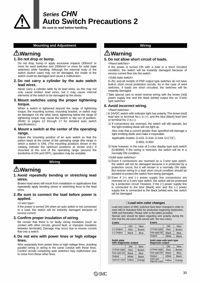
Mounting and Adjustment
1. Do not drop or bump.Do not drop, bump or apply excessive impacts (300m/s² or more for reed switches and 1000m/s² or more for solid state switches) while handling. Although the external body of the switch (switch case) may not be damaged, the inside of the switch could be damaged and cause a malfunction.
2. Do not carry a cylinder by the auto switch lead wires.Never carry a cylinder table by its lead wires, as this may not only cause broken lead wires, but it may cause internal elements of the switch to be damaged by the stress.
3. Mount switches using the proper tightening torque.When a switch is tightened beyond the range of tightening torque, the mounting screws, mounting bracket, or switch may be damaged. On the other hand, tightening below the range of tightening torque may cause the switch to slip out of position. (Refer to pages 12 through 17 for detailed auto switch specifications.)
4. Mount a switch at the center of the operating range.Adjust the mounting position of an auto switch so that the piston stops at the center of the operating range (the range in which a switch is ON). (The mounting positions shown in the catalog indicate the optimum positions at stroke end.) If mounted at the end of the operating range (around the borderline of ON and OFF), operation may be unstable.
Wiring
Warning1. Avoid repeatedly bending or stretching lead
wires.Broken lead wires will result from installation or applications that repeatedly apply bending stress or stretching force to the lead wires.
2. Be sure to connect the load before power is applied.<2-wire type>If the power is turned ON when an auto switch is not connected to a load, the switch will be instantly damaged because of excess current.
3. Confirm proper insulation of wiring.Be certain that there is no faulty wiring insulation (such as contact with other circuits, ground fault, or improper insulation between terminals). Damage may occur due to excess current flow into a switch.
4. Do not wire with power lines or high voltage lines.Wire separately from power lines or high voltage lines, avoiding parallel wiring or wiring in the same conduit with these lines. Control circuits containing auto switches may malfunction due to noise from these other lines.
Wiring
5. Do not allow short circuit of loads.<Reed switches>If the power is turned ON with a load in a short circuited condition, the switch will be instantly damaged because of excess current flow into the switch.
<Solid state switch>D-J51 and all models of PNP output type switches do not have built-in short circuit protection circuits. As in the case of reed switches, if loads are short circuited, the switches will be instantly damaged.
∗ Take special care to avoid reverse wiring with the brown [red] power supply line and the black [white] output line on 3-wire type switches.
6. Avoid incorrect wiring.<Reed switches>
∗ A 24VDC switch with indicator light has polarity. The brown [red] lead wire or terminal No.1 is (+), and the blue [black] lead wire or terminal No. 2 is (–).1) If connections are reversed, the switch will still operate, but
the light emitting diode will not light up.Also note that a current greater than specified will damage a light emitting diode and make it inoperable.Applicable models: D-A33, D-A34, D-A44, D-C73,
D-B53, D-B54
2) Note however, in the case of 2-color display type auto switch (D-B59W), if the wiring is reversed, the switch will be in a normally ON condition.
<Solid state switches>1) Event if connections are reversed on a 2-wire type switch,
the switch will not be damaged because it is protected by a protection circuit, but it will remain in a normally ON state. But reverse wiring in a load short circuit condition should be avoided to protect the switch from being damaged.
∗ 2) Even if (+) and (–) power supply line connections are reversed on a 3-wire type switch, the switch will be protected by a protection circuit. However, if the (+) power supply line is connected to the blue [black] wire and the (–) power supply line is connected to the black [white] wire, the switch will be damaged.
∗ Lead wire color changes
OldRed
Black
NewBrownBlue
(+) Output(–) Output
2-wireOldRed
BlackWhite
NewBrownBlueBlack
(+) Power supplyPower supply GNDOutput
3-wire
OldRed
BlackWhiteYellow
NewBrownBlueBlack
Orange
(+) Power supplyPower supply GNDOutputDiagnostic output
Solid state with diagnostic output
OldRed
BlackWhite
Yellow
NewBrownBlueBlack
Orange
(+) Power supplyPower supply GNDOutputLatch typediagnostic output
Solid state with latch typediagnostic output
Lead wire colors of SMC switches have been changed in order to meet NECA Standard 0402 for production beginning September, 1996 and thereafter. Please refer to the tables provided.Special care should be taken regarding wire polarity during the time that the old colors still coexist with the new colors.

Series CHNAuto Switch Precautions 3Be sure to read before handling.
Warning Warning
Operating Environment
1. Never use in an atmosphere of explosive gases. The construction of auto switches is not intended to prevent explosion. Never use in an atmosphere with an explosive gas since this may cause a serious explosion.
2. Do not use in an area where a magnetic field is generated.Auto switches will malfunction or magnets inside cylinders will become demagnetized. (Consult with SMC regarding the availability of a magnetic field resistant auto switches.)
3. Do not use in an environment where the auto switch will be continually exposed to water.With the exception of some models (D-A3, D-A44, D-G39, D-K39), switches satisfy IEC standard IP67 construction (JIS C 0920: watertight construction). Nevertheless, they should not be used in applications where they are continually exposed to water splash or spray. This may cause deterioration of the insulation or swelling of the potting resin inside switches and may cause a malfunction.
4. Do not use in an environment with oil or chemicals.Consult with SMC if auto switches will be used in an environment laden with coolants, cleaning solvents, various oils, or chemicals. If auto switches are used under these conditions for even a short time, they may be adversely affected by a deterioration of the insulation, a malfunction due to swelling of the potting resin, or hardening of the lead wires.
5. Do not use in an environment with tempera-ture cycles.Consult with SMC if switches are to be used where there are temperature cycles other than normal temperature changes, as they may be adversely affected internally.
6. Do not use in an environment where there is excessive impact shock.<Reed switches>When excessive impact (300m/s² or more) is applied to a reed switch during operation, the contact point may malfunction and generate or cut off a signal momentarily (1ms or less). Consult with SMC regarding the need to use a solid state switch depending on the environment.
7. Do not use in an area where surges are generated.<Solid state switch>When there are units (such as solenoid type lifters, high frequency induction furnaces, motors) that generate a large amount of surge in the area around cylinders with solid state auto switches, their proximity or presence may cause deterioration or damage to the internal circuit elements of the switches. Avoid sources of surge generation and crossed lines.
8. Avoid accumulation of iron waste or close contact with magnetic substances.When a large accumulated amount of ferrous waste such as machining chips or welding spatter, or a magnetic substance (something attracted by a magnet) is brought into close proximity to an cylinder with auto switches, this may cause the auto switches to malfunction due to a loss of the magnetic force inside the cylinder.
Maintenance
1. Perform the following maintenance practices periodically in order to prevent possible dan-ger due to unexpected auto switch malfunc-tion.1) Securely tighten switch mounting screws.
If screws become loose or the mounting position is dislocated, retighten them after readjusting the mounting position.
2) Confirm that there is no damage to lead wires.To prevent faulty insulation, replace switches or repair lead wires if damage is discovered.
3) Confirm that the green light on the 2-color display type switch lights up.Confirm that the green LED is on when stopped at the set position. If the red LED is on, the mounting position is not appropriate. Readjust the mounting position until the green LED lights up.
Other
Warning1. Consult with SMC concerning water resist-
ance, elasticity of lead wires and usage at welding sites.
31

EUROPESLOVENIASMC Industrijska Avtomatika d.o.o.
SPAIN/PORTUGALSMC España, S.A.
SWEDENSMC Pneumatics Sweden AB
SWITZERLANDSMC Pneumatik AG.
UKSMC Pneumatics (U.K.) Ltd.
ASIACHINASMC (China) Co., Ltd.
HONG KONGSMC Pneumatics (Hong Kong) Ltd.
INDIASMC Pneumatics (India) Pvt. Ltd.
MALAYSIASMC Malaysia (S.E.A.) Sdn. Bhd.
PHILIPPINESSMC Pneumatics (Philippines), Inc.
SINGAPORESMC Pneumatics (S.E.A.) Pte. Ltd.SOUTH KOREASMC Pneumatics Korea Co., Ltd.
TAIWANSMC Pneumatics (Taiwan) Co., Ltd.
THAILANDSMC Thailand Ltd.
NORTH AMERICACANADASMC Pneumatics (Canada) Ltd.
MEXICOSMC Corporation (Mexico) S.A. de C.V.USASMC Corporation of America
SOUTH AMERICAARGENTINASMC Argentina S.A.
BOLIVIASMC Pneumatics Bolivia S.R.L.
BRAZILSMC Pneumaticos Do Brazil Ltda.
CHILESMC Pneumatics (Chile) S.A.
VENEZUELASMC Neumatica Venezuela S.A.
OCEANIAAUSTRALIASMC Pneumatics (Australia) Pty. Ltd.
NEW ZEALANDSMC Pneumatics (N.Z.) Ltd.
EUROPEAUSTRIASMC Pneumatik GmbH
CZECHSMC Industrial Automation CZ s.r.o.
DENMARKSMC Pneumatik A/S
FINLANDSMC Pneumatiikka OY
FRANCESMC Pneumatique SA
GERMANYSMC Pneumatik GmbH
HUNGARYSMC Hungary Ipari Automatizálási Kft.
IRELANDSMC Pneumatics (Ireland) Ltd.
ITALYSMC Italia S.p.A.
NETHERLANDSSMC Pnuematics BV.
NORWAYSMC Pneumatics Norway A/S
POLANDSMC Industrial Automation Polska Sp.z.o.o.
ROMANIASMC Romania s.r.l.
RUSSIA SMC Pneumatik LLC.
SLOVAKIASMC Priemyselná automatizáciá, s.r.o.
SMC'S GLOBAL MANUFACTURING, DISTRIBUTION AND SERVICE NETWORK
1-16-4 Shimbashi, Minato-ku, Tokyo 105-0004, JAPANTel: 03-3502-2740 Fax: 03-3508-2480URL http://www.smcworld.com© 2001 SMC CORPORATION All Rights Reserved
1st printing June, 2001 D-SMC.L.A. P-80 (D)This catalog is printed on recycled paper with concern for the global environment.
All specifications in this catalog are subject to change without notice.Printed in Japan.