hydraulic steering systems - propulsion-marine hydraulic steer… · s y s t e m s hydraulic...
TRANSCRIPT

HYDRAULIC
STEERING
SYSTEMS
HYDRAULIC STEERING SYSTEMS
2
INDEX
Introduction 5Company profi le
Hydraulic steering systems composition and working principle 8 Formula for rudder torque calculation 9
Helm pumps 10-17
Outboard cylinders 18-23
Inboard steering systems: 24
>>>Application guide 25-30
>>>Inboard cylinders 31-32
Heavy duty inboard steering systems: 35
>>>Helm pumps 36-38
>>>Order guide 40-49
>>>Inboard cylinders 50-53
Auto-pilot power units 54-59
Power-assisted inboard steering systems: 60-66
>>>Inboard cylinders 67-69
>>>Electro-hydraulic power units 70-71
Accessories 72
Non return valves 72
Rudder angle indicator kits 73
Steering hydraulic oil 73
Filling kit 73
Electric by-pass for auto-pilot power units 73
Steering fl exible hose 74
Inch hoses kit 74-75
Flexible hoses for heavy duty cylinders 76
Fittings kit for inboard and outboard steerings 76
Ball-cock with lever 76
Fittings kit for heavy duty steerings 76
By-pass 76
Fittings 77-79
2

3
Spare parts 80
Helm pumps 80
Outboard steering cylinders 80
Inboard steering cylinders 81-82
Solenoid valves auto-pilot power units 83-84
Reversible auto-pilot power units 84
Solenoid valves auto-pilot power units with automatic fi lling 85
Power-assisted electro-hydraulic power units 85
Warranty conditions 86
International distributors network 87
NOTE: Twin Disc declines any liability for possible mistackes in this catalogue due to printing errors and reserves the right to make any modifi cation that is considered to be necessary or useful for its products. Publishing rights, trade marks, part numbers and photographs present on this catalogue are Twin Disc property or Twin Disc has the necessary authorization to use them. So, all rights are reserved and any reproduction, even partial, is forbidden.Our products cannot be installed on racing boats without our previous authorization.

44
Twin Disc - BCS: solutions, innovation, quality.

5
Production plants of Limite sull’Arno
1956, BCS s.r.l. was founded2006, Twin Disc Inc. acquired BCS s.r.l.2007, Incorporation of BCS s.r.l. in Twin Disc S.r.l.
BCS has been the leading company for the last 50 years in the manufacturing and distribution of marine equipments worldwide. The acquisition by Twin Disc Inc. – leader in several different areas such as marine and industrial, heavy duty transmissions and the oil extraction industry – has consolidated Twin Disc position on the market as a part of a multinational group. BCS, BCS Service, Twin Disc Technodrive, Twin Disc Propulsion have then merged together creating one company, Twin Disc S.r.l., supported by the additional value of the sister-company Rolla SP Propellers.
Global “package”Twin Disc S.r.l. offers to boat builders and design engineers a complete ”package” of products, such as propulsion systems, gearboxes, transmissions, control and steering systems, together with customized solutions and effi cient technical support. Twin Disc offers a global customer service for the development and realization of the whole kinematics system. A dynamic team of engineers, technicians and professional people is devoted to help customers in any step: development, planning, prototyping, design defi nition, bench and fi eldtesting, production, assembly, installation and service on board. Day by day, Twin Disc S.r.l. works alongside customers.
The ability to understand and anticipate market needs, the certifi ed products, specialized service, together with the continuous research and innovation technology, forms a unique worldwide system dedicated to the marine industry.
Twin Disc provides the following product range: hydraulic and electronic steering systems, complete shaft lines for boats up to 40 meters, trim tab systems either in stainless steel or aluminum, bow and stern thrusters, both electric and hydraulic, electro-hydraulic gangways and side ladders for big applications, as well as a large variety of stainless steel hydraulic actuators and multi-function electro-hydraulic power units.

66

7
From the concept to the production:
prototype development, care for design, field testing, product definition.
Twin Disc Srl is certifi ed by Registro Italiano Navale (RINA) according to the requirements of the standards UNI EN ISO 9001:2000.
All the management and production processes of the company, from the material research and the design of products, up to the planning of the production cycles, checking tests and shipping management, undergo the constant verifi cation of the strictest quality criteria in order to guarantee the highest reliability level.
As a result of more than 50 years of experience, the steering systems are a synthesis between selected materials, innovative design and state-of-art technical solutions.All the components are built with high precision systems and tooling and meet the requirements of the best survey authorities such as: Rina Lloyd’s Register, ABS, Bureau Veritas etc. As a further guarantee of effi ciency and durability, certifi cates for special applications are also available upon request.
Conforming with the Standard 94/25/CE, as amended by the Standard 2003/44/CE, and also included in the Type Accepted of Program NMMA, hydraulic pumps and cylinders covers any type of application: outboard, stern-drives and inboard systems for pleasure and commercial vessels.

8
HYDRAULIC STEERING SYSTEMSCOMPOSITION AND WORKING PRINCIPLE
4. Fly helm pump
1. Main station helm pump
3. Hoses
Cylinder fl exible hosing2. Hydraulic cylinder
A
C
5. Auto-pilot power unit6. Relief valve
B
Note: in case of dual station, the oil cap of the pilot house shall be closed. If a power unit with automatic filling is installed both caps shall be closed.
In order to get the best control with the minimum effort, the steering system must match the specifi c vessel’s requirements.A standard steering system in its basic composition is composed by three major elements such as:- hydraulic helm pump (1) of the axial piston type, which pumps
oil into the system each time the steering wheel is turned. The pump is provided with a non return (lock) valve, to prevent any uncontrolled movement of the rudder, and with a relief valve to protect the steering system from any sudden and excessive increase in pressure;
- hydraulic cylinder (2) is the real rudder actuator and determines the power of the system. It is therefore important to select the right cylinder model for the required torque (see page 27-44-66 for cylinder selection).
The pump and the cylinder are connected together by means of:- rigid or fl exible hoses (3) suitable for hydraulic applications
and sized according to the pump displacement. The rigid piping system guarantees the best steering performance. A fl exible hose system can be used for rudder torque not higher than 290 Kg/m (24.675 lb.in.).
To satisfy different needs, or adapt to specifi c solutions, this basic confi guration can be integrated with many other steering components such as:- hydraulic helm pumps for additional control stations (4);- auto-pilot power units (5) are available in a wide range of
displacements and they can be combined with different steering cylinders with a capacity of up to 3900 cc;
- valves and accessories (6) (see section “steering accessories” from page 75).
The working principle of the basic steering system is very simple:A. By turning the steering wheel in one direction oil fl ow goes
from the helm pump to the steering cylinder.B. This fl ow, which enters the cylinder, moves the piston, as well
as the rod connected to the tiller arm, in order to allow the rudder to rotate.
C. Oil displaced from the opposite side of the cylinder fl ows back to the helm pump.
D. By rotating the rudder in the opposite direction, simply turn the helm pump the other way.
HYD
RAU
LIC STEERIN
GS

9
HYD
RAU
LIC
STE
ERIN
GS
Formula for rudder torque calculationfor each rudder with an angle of 35°
a = rudder height in metersb = rudder beam in metersc = compensation distance in metersd = arm = distance between the rudder axis
and pressure pointS = forceV = max speed in knotsA = total area in square meters=(axb)
d = (0,372 x b) – cS = 8,16 x V2 x A
Mt = rudder torque in Kgm = S x d
Example:
a = 1,10 mtb = 0,65 mtc = 0,21 mt V = 18 knotsd = (0,372 x 0,65) – 0,21 = 0,03A = 1,10x0,65 = 0,71 mt2
S = 8,16 x 324 x 0,71 = 1.877,12 Kg
Mt = 1.877,12 x 0,03 = 56,31 Kgm
Note: in case the vessel is equipped with two rudders the total torque will be:
Mt = 2 x 56,31 = 112,62 Kgm
HOW TO SELECT THE SUITABLE SYSTEM
The steering system determines boat maneuverability, ease of control and reliability. Model choice and confi guration will be based on boat’s requirements and user’s needs.Below is a list of the necessary steps to select the most suitable system, either for boats equipped with outboard engines (A), or for boats equipped with inboard engines (B). The following pages provide customers with a range of steering components and an Order Guide helps in the selection and suggests how to size them.
A. BOATS EQUIPPED WITH OUTBOARD ENGINES
1. Determine the number of outboard engines the boat has;2. Determine the total engines power (i.e.: horsepower) reminding that: - if there are two engines with the same rotation direction you need to add their powers; - if there are two counter-rotating engines, you need to consider the one engine power.
Example:no. 1 engine of 300 Hp total power 300 Hpno. 2 engine of 150 Hp - same rotation direction total power 300 Hpno. 1 engine of 300 Hp - opposite rotation direction total power 150 Hp
B. BOATS EQUIPPED WITH RUDDERS WHOSE MAX speed is below 28 knots
1. Calculate the required rudder torque (i.e.: Kgm or lb.in.) according to the formula below. Bear in mind that the max rudder torque of a boat depends on:
- boat max speed;- rudder’s dimensions and shape;- rudder compensation surface.
2. Determine the number of rudders in order to obtain the total rudder torque.
Note: an important factor for the choice of the steering cylinder is the type of hull (i.e.: planing or displacement) as it can infl uence the vessel speed:• planing hull: max speed > 18 knots • displacement hull: max speed < 18 knots.
Once the rudder torque has been calculated and the most suitable steering cylinder has been selected, you need to determine the size of the hydraulic helm pump, whose choice depends on the following options:
A. total number of wheel turns lock-to-lock (*);
B. number of the control stations;
C. helm pump mounting confi guration (frontal, intermediate, rear or tilt mounting).
(*) Note: the total number of wheel turns lock-to-lock depends on cylinder volume and helm displacement (divide the cylinder volume by the helm pump displacement).
The necessary effort on the steering wheel is inversely proportional to the total number of wheel turns lock-to-lock. Therefore:- less wheel turns lock-to-lock result in more wheel effort on the steering wheel;- more wheel turns lock-to-lock result in less wheel effort on the steering wheel.
ATTENTION! In case a helm pump with a higher displacement is chosen, to decrease the total wheel turns lock-to-lock (within the limitations indicated on the tables), you need to install a wheel with a bigger diameter.
10
FRONTAL mount helm(basic helm)
Basic helm + REAR mounting kit
Basic helm + INTERMEDIATE mounting kit
HELM PUMPS
Helm with Tilt SPORT
HELM
PUM
PS
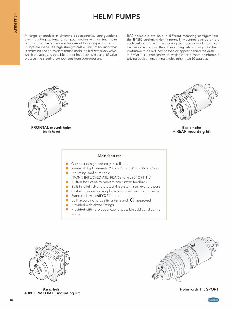
A range of models in different displacements, confi gurations and mounting options: a compact design with minimal helm protrusion is one of the main features of this axial-piston pump. Pumps are made of a high strength cast aluminum housing, that is corrosion and abrasion resistant, and supplied with a lock valve, which prevents any possible rudder feedback, while a relief valve protects the steering components from over-pressure.
BCS helms are available in different mounting confi gurations: the BASIC version, which is normally mounted outside on the dash surface and with the steering shaft perpendicular to it, can be combined with different mounting kits allowing the helm protrusion to be reduced or even disappear behind the dash.A SPORT TILT mechanism is available for a more comfortable driving position (mounting angles other than 90 degrees).
Compact design and easy installationRange of displacements: 20 cc - 25 cc - 30 cc - 35 cc - 42 ccMounting confi gurations: FRONT, INTERMEDIATE, REAR and with SPORT TILTBuilt-in lock valve to prevent any rudder feedbackBuilt-in relief valve to protect the system from over-pressureCast aluminium housing for a high resistance to corrosionPump shaft with ABYC 3/4 taperBuilt according to quality criteria and approvedProvided with elbow fi ttings Provided with no-bleeder cap for possible additional control station
Main features

11
HELM PUMP
Model Displacement Code
P20BAP 20 cc/rev 21173
P20BA 1.22 cu.in/rev 16192
P30BAP 30 cc/rev 21174
P30BA 1.83 cu.in/rev 16193
P42BAP 42cc/rev 21175
P42BA 2.56 cu.in/rev 16194
Helm pumps 20 cc - 30 cc - 42 ccFRONTAL mounting (basic helm)
Mounting configurationFRONTAL mounting
FRONTAL mounting helm - Technical specifi cations
Model Mountingconfiguration
Non return valve
Reilef valve Displacement Nr
pistons
Relief valve setting
pressureFittings included Min. wheel Max.
wheel Weight
P20BAPFrontal Yes Yes
20 cc/rev 5
70 bar 1/4”NPTF - 3/8” D.E. 350 mm 711 mm 2.6 Kg
P20BA 1.22 cu.in/rev 1000 psi G1/4” - hose d. 10 13,78 in. 28 in. 5.8 lb
P30BAPFrontal Yes Yes
30 cc/rev5
70 bar 1/4”NPTF - 3/8” D.E. 350 mm 711 mm 3.0 Kg
P30BA 1.83 cu.in/rev 1000 psi G1/4” - hose d. 10 13,78 in. 28 in. 6.7 lb
P42BAPFrontal Yes Yes
42 cc/rev7
70 bar 1/4”NPTF - 3/8” D.E.1/4”NPTF - 1/2” D.E.
450 mm 711 mm 3.0 Kg
P42BA 2.56 cu.in/rev 1000 psiG1/4” - hose d. 10G1/4” - hose d. 12 17,72 in. 28 in. 6.7 lb
N° 4 M6 (0,24”)
67 mm (2,6”)
ø 76
mm
(3”)
67 m
m (2
,6”)
31,5 mm (1,25”)
20 mm (0,79”)
203,5 mm (8”)
109 mm (4,25”)
8,5 mm (0,35”)
54 mm (2,13”)
45 mm (1,8”)
ø25
mm
(0,9
8”)
ø111
mm
(4,3
5”)
5 m
m (0
,2”)
ø115
mm
(4,5
”)2,386°(2°23’9,5”)
19,7
4 m
m (0
,78”
)
HEL
M P
UM
PS
Order Guide
Metrical fittingsImperial fittings

12
HELM
PUM
PS
HELM PUMP
Model Displacement Code
P20BAP + Kit MK10 20 cc/rev 21173+16199
P20BA + Kit MK10 1.22 cu.in/rev 16192+16199
P30BAP + Kit MK10 30 cc/rev 21174+16199
P30BA + Kit MK10 1.83 cu.in/rev 16193+16199
P42BAP + Kit MK10 42 cc/rev 21175+16199
P42BA + Kit MK10 2.56 cu.in/rev 16194+16199
102 mm (4”)132,5 mm (5,22”)
132,
5 m
m (5
,22”
)
102
mm
(4”)
203,8 mm (8”)41 mm (1,61”) 113 mm (4,41”) 50 mm
(1,97”)15 mm(0,59”) M
6
4 mm (0,16”)
MAX 50 mm - MIN 10 mm(MAX. 1,97” - MIN 0,39”)
2,38
6°2°
23’9,
5”
19,74 mm (0,78”)
Model Mountingconfiguration
Non return valve
Reilef valve Displacement Nr
pistons
Relief valve setting
pressureFittings included Min.
wheelMax. wheel Weight
P20BAP + MK10Intermediate Yes Yes
20 cc/rev5
70 bar 1/4”NPTF - 3/8” D.E. 350 mm 711 mm 2.6 Kg
P20BA + MK10 1.22 cu.in/rev 1000 psi G1/4” - hose d. 10 13,78 in. 28 in. 5.8 lb
P30BAP + MK10Intermediate Yes Yes
30 cc/rev5
70 bar 1/4”NPTF - 3/8” D.E. 350 mm 711 mm 3.0 Kg
P30BA + MK10 1.83 cu.in/rev 1000 psi G1/4” - hose d. 10 13,78 in. 28 in. 6.7 lb
P42BAP + MK10Intermediate Yes Yes
42 cc/rev7
70 bar 1/4”NPTF - 3/8” D.E.1/4”NPTF - 1/2” D.E.
450 mm 711 mm 3.0 Kg
P42BA + MK10 2.56 cu.in/rev 1000 psi G1/4” - hose d. 10G1/4” - hose d. 12
17,72 in. 28 in. 6.7 lb
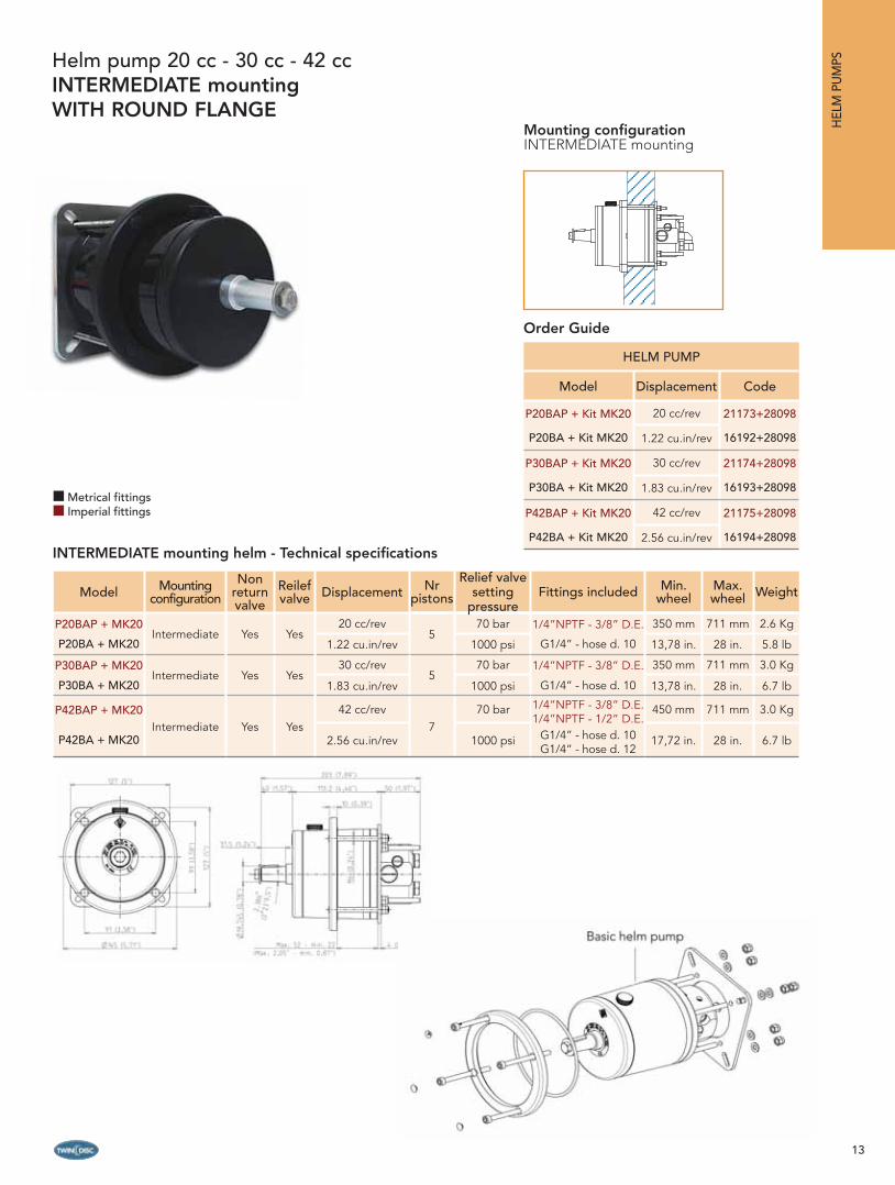
Helm pump 20 cc - 30 cc - 42 ccINTERMEDIATE mounting
Mounting configurationINTERMEDIATE mounting
INTERMEDIATE mounting helm - Technical specifi cations
Metrical fittingsImperial fittings
Order Guide
Intermediate Mount Kit mod. MK10
Basic Helm
13
HEL
M P
UM
PS
HELM PUMP
Model Displacement Code
P20BAP + Kit MK20 20 cc/rev 21173+28098
P20BA + Kit MK20 1.22 cu.in/rev 16192+28098
P30BAP + Kit MK20 30 cc/rev 21174+28098
P30BA + Kit MK20 1.83 cu.in/rev 16193+28098
P42BAP + Kit MK20 42 cc/rev 21175+28098
P42BA + Kit MK20 2.56 cu.in/rev 16194+28098
Model Mountingconfiguration
Non return valve
Reilef valve Displacement Nr
pistons
Relief valve setting
pressureFittings included Min.
wheelMax. wheel Weight
P20BAP + MK20Intermediate Yes Yes
20 cc/rev5
70 bar 1/4”NPTF - 3/8” D.E. 350 mm 711 mm 2.6 Kg
P20BA + MK20 1.22 cu.in/rev 1000 psi G1/4” - hose d. 10 13,78 in. 28 in. 5.8 lb
P30BAP + MK20Intermediate Yes Yes
30 cc/rev5
70 bar 1/4”NPTF - 3/8” D.E. 350 mm 711 mm 3.0 Kg
P30BA + MK20 1.83 cu.in/rev 1000 psi G1/4” - hose d. 10 13,78 in. 28 in. 6.7 lb
P42BAP + MK20Intermediate Yes Yes
42 cc/rev7
70 bar 1/4”NPTF - 3/8” D.E.1/4”NPTF - 1/2” D.E.
450 mm 711 mm 3.0 Kg
P42BA + MK20 2.56 cu.in/rev 1000 psi G1/4” - hose d. 10G1/4” - hose d. 12
17,72 in. 28 in. 6.7 lb
Helm pump 20 cc - 30 cc - 42 ccINTERMEDIATE mountingWITH ROUND FLANGE
Mounting configurationINTERMEDIATE mounting
INTERMEDIATE mounting helm - Technical specifi cations
Metrical fittingsImperial fittings
Order Guide

14
HELM
PUM
PS
20 mm (0,79”)2 mm (0,08”)
5 m
m (0
,2”)
ø116mm (4,6”)
59 (2,4”)
31,5 mm (1,24”)
2,38
6°2°
23’9,
5”
250 mm (9,84”)
106 mm (4,17”) 53 mm (2,09”)
ø115
mm
(4,5
3”)
ø30
(1,1
8”) m
m
27 mm (1”)
Model Mountingconfiguration
Non return valve
Reilef valve Displacement Nr
pistons
Relief valve setting
pressureFittings included Min.
wheelMax. wheel Weight
P20BAP + MK30Rear Yes Yes
20 cc/rev5
70 bar 1/4”NPTF - 3/8” D.E. 350 mm 711 mm 2.6 Kg
P20BA + MK30 1.22 cu.in/rev 1000 psi G1/4” - hose d. 10 13,78 in. 28 in. 5.8 lb
P30BAP + MK30Rear Yes Yes
30 cc/rev5
70 bar 1/4”NPTF - 3/8” D.E. 350 mm 711 mm 3.0 Kg
P30BA + MK30 1.83 cu.in/rev 1000 psi G1/4” - hose d. 10 13,78 in. 28 in. 6.7 lb
P42BAP + MK30Rear Yes Yes
42 cc/rev7
70 bar 1/4”NPTF - 3/8” D.E.1/4”NPTF - 1/2” D.E.
450 mm 711 mm 3.0 Kg
P42BA + MK30 2.56 cu.in/rev 1000 psiG1/4” - hose d. 10G1/4” - hose d. 12 17,72 in. 28 in. 6.7 lb
HELM PUMP
Model Displacement Code
P20BAP + Kit MK30 20 cc/rev 21173+16198
P20BA + Kit MK30 1.22 cu.in/rev 16192+16198
P30BAP + Kit MK30 30 cc/rev 21174+16198
P30BA + Kit MK30 1.83 cu.in/rev 16193+16198
P42BAP + Kit MK30 42 cc/rev 21175+16198
P42BA + Kit MK30 2.56 cu.in/rev 16194+16198
Helm pump 20 cc - 30 cc - 42 ccREAR mounting
Mounting configurationREAR mounting
REAR mounting helm - Technical specifi cations
Note: this pump is also available with plastic cromate cover (Kit MK31 - cod. 23277). All rear mounting helm pumps are also available without fl ange (Kit MK50 - cod. 23180). For this model we suggest purchasing the fi lling kit mod. K100 (oil fi lling kit code 18599). See the “Steering accessories” section on page 73.
Metrical fittingsImperial fittings
Order Guide
Basic Helm
Rear mount kitmod. MK30

15
Model Mountingconfiguration
Non return valve
Reilef valve Displacement Nr
pistons
Relief valve setting
pressureFittings included Min.
wheelMax. wheel Weight
P20BAP + MK60Rear Yes Yes
20 cc/rev5
70 bar 1/4”NPTF - 3/8” D.E. 350 mm 711 mm 2.6 Kg
P20BA + MK60 1.22 cu.in/rev 1000 psi G1/4” - hose d. 10 13,78 in. 28 in. 5.8 lb
P30BAP + MK60Rear Yes Yes
30 cc/rev5
70 bar 1/4”NPTF - 3/8” D.E. 350 mm 711 mm 3.0 Kg
P30BA + MK60 1.83 cu.in/rev 1000 psi G1/4” - hose d. 10 13,78 in. 28 in. 6.7 lb
P42BAP + MK60Rear Yes Yes
42 cc/rev7
70 bar 1/4”NPTF - 3/8” D.E.1/4”NPTF - 1/2” D.E.
450 mm 711 mm 3.0 Kg
P42BA + MK60 2.56 cu.in/rev 1000 psiG1/4” - hose d. 10G1/4” - hose d. 12 17,72 in. 28 in. 6.7 lb
HELM PUMP
Model Displacement Code
P20BAP + Kit MK60 20 cc/rev 21173+28064
P20BA + Kit MK60 1.22 cu.in/rev 16192+28064
P30BAP + Kit MK60 30 cc/rev 21174+28064
P30BA + Kit MK60 1.83 cu.in/rev 16193+28064
P42BAP + Kit MK60 42 cc/rev 21175+28064
P42BA + Kit MK60 2.56 cu.in/rev 16194+28064
Helm pump 20 cc - 30 cc - 42 ccREAR mountingWITH OPEN STAINLESS STEEL COVER
Mounting configurationREAR mounting
REAR mounting helm - Technical specifi cations
Note: all rear mounting helm pumps are also available without fl ange (Kit MK50 - cod. 23180). For this model we suggest purchasing the fi lling kit mod. K100 (oil fi lling kit code 18599). See the “Steering accessories” section on page 73.
Metrical fittingsImperial fittings
Order Guide
HEL
M P
UM
PS
16
HELM
PUM
PS
20 mm (0,79”)2 mm (0,08”)
5 m
m (0
,2”)
ø116mm (4,6”)
59 (2,4”)
31,5 mm (1,24”)
2,38
6°2°
23’9,
5”
250 mm (9,84”)
106 mm (4,17”) 53 mm (2,09”)
ø115
mm
(4,5
3”)
ø30
(1,1
8”) m
m
27 mm (1”)
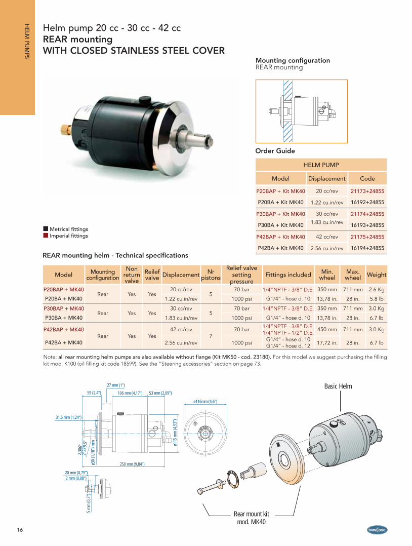
Model Mountingconfiguration
Non return valve
Reilef valve Displacement Nr
pistons
Relief valve setting
pressureFittings included Min.
wheelMax. wheel Weight
P20BAP + MK40Rear Yes Yes
20 cc/rev5
70 bar 1/4”NPTF - 3/8” D.E. 350 mm 711 mm 2.6 Kg
P20BA + MK40 1.22 cu.in/rev 1000 psi G1/4” - hose d. 10 13,78 in. 28 in. 5.8 lb
P30BAP + MK40Rear Yes Yes
30 cc/rev5
70 bar 1/4”NPTF - 3/8” D.E. 350 mm 711 mm 3.0 Kg
P30BA + MK40 1.83 cu.in/rev 1000 psi G1/4” - hose d. 10 13,78 in. 28 in. 6.7 lb
P42BAP + MK40Rear Yes Yes
42 cc/rev7
70 bar 1/4”NPTF - 3/8” D.E.1/4”NPTF - 1/2” D.E.
450 mm 711 mm 3.0 Kg
P42BA + MK40 2.56 cu.in/rev 1000 psiG1/4” - hose d. 10G1/4” - hose d. 12 17,72 in. 28 in. 6.7 lb
HELM PUMP
Model Displacement Code
P20BAP + Kit MK40 20 cc/rev 21173+24855
P20BA + Kit MK40 1.22 cu.in/rev 16192+24855
P30BAP + Kit MK40 30 cc/rev 21174+24855
P30BA + Kit MK40 1.83 cu.in/rev 16193+24855
P42BAP + Kit MK40 42 cc/rev 21175+24855
P42BA + Kit MK40 2.56 cu.in/rev 16194+24855
Helm pump 20 cc - 30 cc - 42 ccREAR mountingWITH CLOSED STAINLESS STEEL COVER
Mounting configurationREAR mounting
Note: all rear mounting helm pumps are also available without fl ange (Kit MK50 - cod. 23180). For this model we suggest purchasing the fi lling kit mod. K100 (oil fi lling kit code 18599). See the “Steering accessories” section on page 73.
Metrical fittingsImperial fittings
REAR mounting helm - Technical specifi cations
Order Guide
Basic Helm
Rear mount kitmod. MK40
17
Model Mountingconfiguration
Non return valve
Reilef valve Displacement Nr
pistons
Relief valve setting
pressureFittings included Min.
wheelMax. wheel Weight
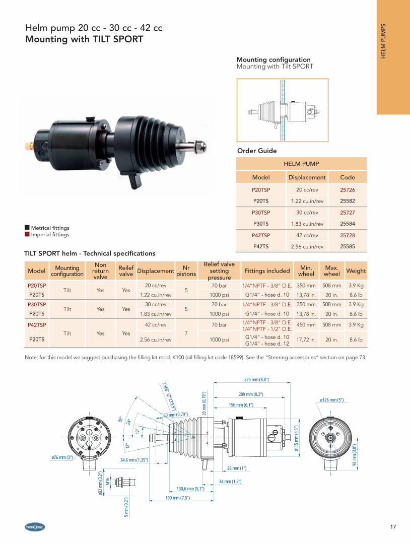
P20TSPTilt Yes Yes
20 cc/rev5
70 bar 1/4”NPTF - 3/8” D.E. 350 mm 508 mm 3.9 Kg
P20TS 1.22 cu.in/rev 1000 psi G1/4” - hose d. 10 13,78 in. 20 in. 8.6 lb
P30TSPTilt Yes Yes
30 cc/rev5
70 bar 1/4”NPTF - 3/8” D.E. 350 mm 508 mm 3.9 Kg
P20TS 1.83 cu.in/rev 1000 psi G1/4” - hose d. 10 13,78 in. 20 in. 8.6 lb
P42TSP
Tilt Yes Yes
42 cc/rev
7
70 bar 1/4”NPTF - 3/8” D.E.1/4”NPTF - 1/2” D.E.
450 mm 508 mm 3.9 Kg
P20TS 2.56 cu.in/rev 1000 psi G1/4” - hose d. 10G1/4” - hose d. 12
17,72 in. 20 in. 8.6 lb
Helm pump 20 cc - 30 cc - 42 ccMounting with TILT SPORT
TILT SPORT helm - Technical specifi cations
Mounting configurationMounting with Tilt SPORT
ø76 mm (3”)
ø82
mm
(3,2
”)M
16
5 m
m (0
,2”)
34,6 mm (1,35”)
190 mm (7,5”)
130,6 mm (5,1”)
34 mm (1,3”)
26 mm (1”)
156 mm (6,1”)
209 mm (8,2”)
225 mm (8,8”)
ø126 mm (5”)
98 m
m (3
,8”)
ø115
mm
(4,5
”)
20 m
m (0
,79”
)
20 mm (0,79”)
2.386° (2°23’9,5”)
36°
24°
12°
12°
HELM PUMP
Model Displacement Code
P20TSP 20 cc/rev 25726
P20TS 1.22 cu.in/rev 25582
P30TSP 30 cc/rev 25727
P30TS 1.83 cu.in/rev 25584
P42TSP 42 cc/rev 25728
P42TS 2.56 cu.in/rev 25585
Note: for this model we suggest purchasing the fi lling kit mod. K100 (oil fi lling kit code 18599). See the “Steering accessories” section on page 73.
HEL
M P
UM
PS
Metrical fittingsImperial fittings
Order Guide

18
OUTBOARD CYLINDERSFRONT MOUNTING
Reliability, quality and comfort.Outboard steering can be adapted to the different mounting confi gurations to cover any outboard application: this is the best alternative for mechanical steering.Suitable for single and multiple outboards up to 300 hp (600 hp with combined counter-rotating engines), the outboard steering is the ideal solution for runabouts, cruisers, and infl atables, with either single or dual engine; they can also be used on work, commercial or rescue boats, which normally require high performances in severe service conditions.
Built with high-quality materials, suitable to work in a marine environment, compact design; the outboard steering cylinders are suitable for most splash-well confi gurations.The balanced front mounting cylinders allow the engine full and free movement with minimum dimensions.They can be combined with a wide range of accessories, such as helm pumps, hoses in the necessary length, inch fi ttings and hydraulic oil for a complete steering package.
SINGLE STATION DUAL STATION
OU
TBOA
RD C
YLIND
ERS
Elegant and compact design that fi ts most splashwellsHard chromed stainless steel piston rodBalanced frontal mounting cylinderSuitable for single and twin engine applicationsSuitable for outboards up to 150 hp for the model OB-108 and 300 hp for the model OB-133 (600 hp if combined with counter-rotating outboard engines) with a max speed of 60 ktsCombined with BCS helms, tubing, fi ttings and oil provides a complete package of easy installation Meets ABYC standards approved
Main features
19
DUAL STATIONSINGLE STATION
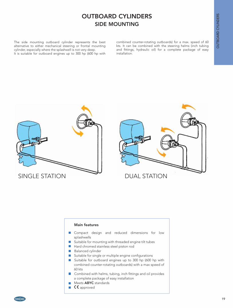
OUTBOARD CYLINDERSSIDE MOUNTING
OU
TBO
ARD
CYL
IND
ERS
The side mounting outboard cylinder represents the best alternative to either mechanical steering or frontal mounting cylinder, especially where the splashwell is not very deep.It is suitable for outboard engines up to 300 hp (600 hp with
combined counter-rotating outboards) for a max. speed of 60 kts. It can be combined with the steering helms (inch tubing and fi ttings, hydraulic oil) for a complete package of easy installation.
Main features
Compact design and reduced dimensions for low splashwellsSuitable for mounting with threaded engine tilt tubesHard chromed stainless steel piston rodBalanced cylinder Suitable for single or multiple engine confi gurationsSuitable for outboard engines up to 300 hp (600 hp with combined counter-rotating outboards) with a max speed of 60 ktsCombined with helms, tubing, inch fi ttings and oil provides a complete package of easy installationMeets ABYC standards approved

20
Minimum splashwell dimensions
Cylinder model
Number of engines A B C
OB-108
1609,6 mm 203 mm 153 mm
24 in. 7.99 in. 6.02 in.
21219,2 mm 203 mm 178 mm
48 in. 7.99 in. 7 in.
OB-133
1698,5 mm 203 mm 153 mm
27.5 in. 7.99 in. 6.02 in.
21397 mm 203 mm 178 mm
55 in. 7.99 in. 7 in.
Front mounting outboard cylindersCylinder mod. OB-108
Dimensions A+B+C
Dimensions
Model A B C D E F G H I L M
OB-108576 mm 75 mm 320 mm 125 mm 18 mm 15,8 mm 432 mm 38 mm 25mm 51 mm 146,5 mm
22.67 in. 2.95 in. 12.59 in. 4.92 in. 0.70 in. 0.62 in. 17 in. 1.49 in. 0.98 in. 2 in. 7.76 in.
OB-133667.3 mm 75 mm 317.3 mm 147 mm 18 mm 15.8 mm 430 mm 38 mm 25 mm 51 mm 147 mm26,27 in. 2,95 in. 12.49 in. 5.7 in. 0.70 in. 0.62 in. 16.92 in. 1.49 in. 0.98 in. 2.0 in. 5.78 in.
Technical specifi cations
Mod. Code Stroke Force at 70 bar/ 1000 psi
Vol. Fittings Engine power
Max. speed
OB-108 19304
197.0 mm 385 Kgf 108 cc 1/4”
NPTF -
3/8” D.E.
150 Hp 85 Km/h
7.75 in 848 lbf 6.6 cu.in 110 Kw 45 kts
OB-133 20932
241.3 mm 385 Kgf 133 cc 1/4”
NPTF -
3/8” D.E.
300 Hp 110 Km/h
9.5 in 848 lbf 8.1 cu.in 221 Kw 60 kts
Note: the front mounting cylinders mod. OB-108 and OB-133 are not suitable for installations where the boat max speed exceeds 85 km/h (45 kts) for mod. OB-108 and 110 Km/h (60 kts) for mod. OB-133 and for any application on racing boats.
OU
TBOA
RD C
YLIND
ERS
21
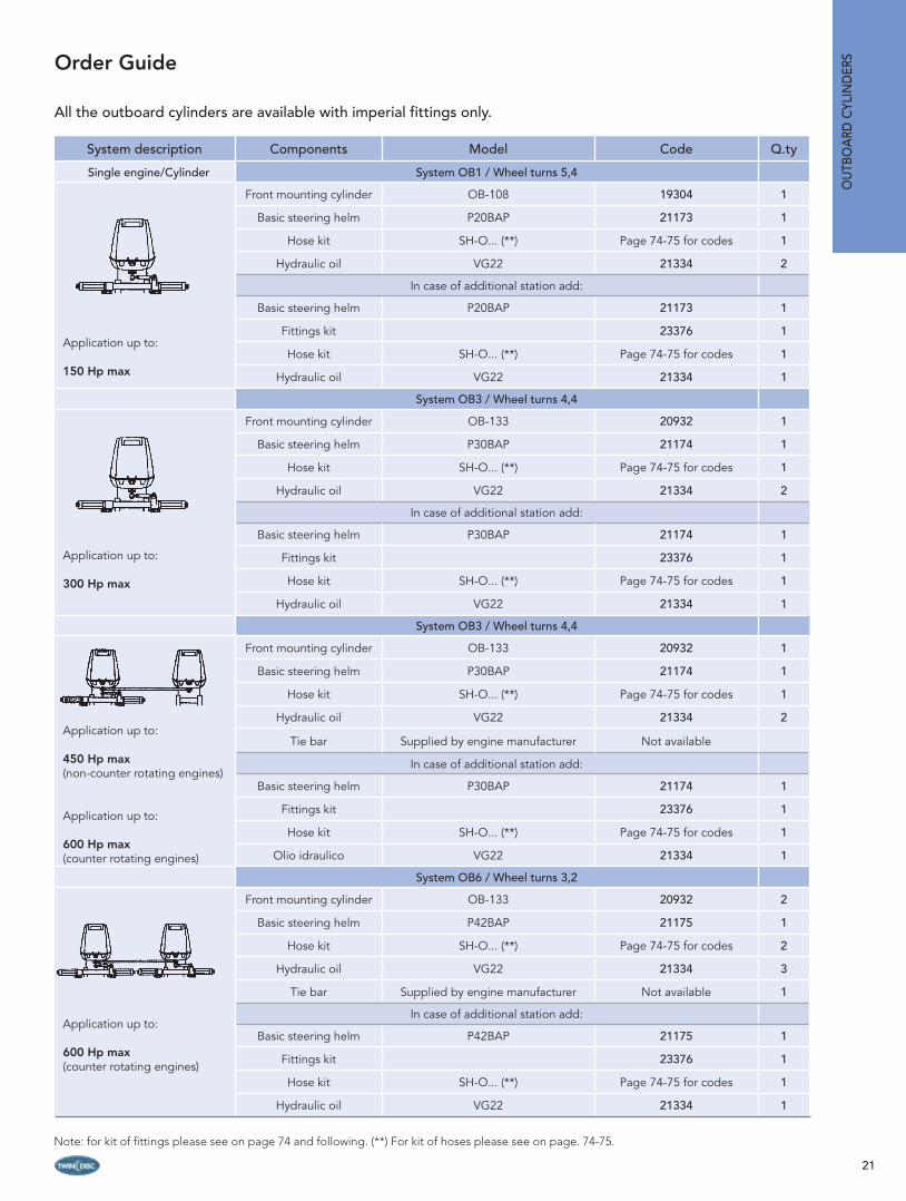
Note: for kit of fi ttings please see on page 74 and following. (**) For kit of hoses please see on page. 74-75.
Order Guide
System description Components Model Code Q.ty
Single engine/Cylinder System OB1 / Wheel turns 5,4
Application up to:
150 Hp max
Front mounting cylinder OB-108 19304 1
Basic steering helm P20BAP 21173 1
Hose kit SH-O... (**) Page 74-75 for codes 1
Hydraulic oil VG22 21334 2
In case of additional station add:
Basic steering helm P20BAP 21173 1
Fittings kit 23376 1
Hose kit SH-O... (**) Page 74-75 for codes 1
Hydraulic oil VG22 21334 1
System OB3 / Wheel turns 4,4
Application up to:
300 Hp max
Front mounting cylinder OB-133 20932 1
Basic steering helm P30BAP 21174 1
Hose kit SH-O... (**) Page 74-75 for codes 1
Hydraulic oil VG22 21334 2
In case of additional station add:
Basic steering helm P30BAP 21174 1
Fittings kit 23376 1
Hose kit SH-O... (**) Page 74-75 for codes 1
Hydraulic oil VG22 21334 1
System OB3 / Wheel turns 4,4
Application up to:
450 Hp max (non-counter rotating engines)
Application up to:
600 Hp max (counter rotating engines)
Front mounting cylinder OB-133 20932 1
Basic steering helm P30BAP 21174 1
Hose kit SH-O... (**) Page 74-75 for codes 1
Hydraulic oil VG22 21334 2
Tie bar Supplied by engine manufacturer Not available
In case of additional station add:
Basic steering helm P30BAP 21174 1
Fittings kit 23376 1
Hose kit SH-O... (**) Page 74-75 for codes 1
Olio idraulico VG22 21334 1
System OB6 / Wheel turns 3,2
Application up to:
600 Hp max(counter rotating engines)
Front mounting cylinder OB-133 20932 2
Basic steering helm P42BAP 21175 1
Hose kit SH-O... (**) Page 74-75 for codes 2
Hydraulic oil VG22 21334 3
Tie bar Supplied by engine manufacturer Not available 1
In case of additional station add:
Basic steering helm P42BAP 21175 1
Fittings kit 23376 1
Hose kit SH-O... (**) Page 74-75 for codes 1
Hydraulic oil VG22 21334 1
OU
TBO
ARD
CYL
IND
ERS
All the outboard cylinders are available with imperial fittings only.

22
Minimum splashwell dimensions
Cylindermodel
Number of engines A
OB-163SY 1530 mm20,8 in.
Technical specifi cations
Model Code Stroke Force at 70 bar/1000 psi Volume Engine
power Max.
speed
OB-163SY 20928203.0 mm 455 - 562 Kgf 132.11 - 163.34 cc. 300 Hp 85 Km/h
8.0 in 1003 -1238 lbf 8.05 - 9.97 cu.in 221 Kw 45 kts
Note: the side mounting cylinder mod. OB-163SY is not suitable for installations where the boat max speed exceeds 110 Km/h (60 kts) and for any application on racing boats.
Side mounting outboard cylinder Cylinder mod. OB-163SY
Dimensions
653 mm (25,7”)
344,5 mm (13,56”)ø3
2 m
m (1
,25”
)
ø38
mm
(1,5
”)
ø9,8 mm (0,38”)
9,5
mm
(0,3
7”)
ø15,8 mm (0,62”)
327 mm (12,87”)
OU
TBOA
RD C
YLIND
ERS

23
Order Guide
System description Components Model Code Q.ty
Single engine/Cylinder System OB8 / Wheel turns 6,6 / 8,1
Application up to:
300 Hp max
Side mounting cylinder OB-163SY 20928 1
Basic steering helm P20BAP 21173 1
Hose kit SH-O... (**) Page 74-75 for codes 1
Hydraulic oil VG22 21334 3
In case of additional station add:
Basic steering helm P20BAP 21173 1
Fittings kit 23376 1
Hose kit SH-O... (**) Page 74-75 for codes 1
Hydraulic oil VG22 21334 1
Double engine/Single cylinder System OB10 / Wheel turns 4,4 / 5,4
Application up to:
300 Hp max (non-counter rotating engines)
Application up to:
600 Hp max(counter rotating engines)
Side mounting cylinder OB-163SY 20928 1
Basic steering helm P30BAP 21174 1
Hose kit SH-O... (**) Page 74-75 for codes 1
Hydraulic oil VG22 21334 3
Tie bar supplied by engine manufacturer Not available 1
In case of additional station add:
Basic steering helm P30BAP 21174 1
Fittings kit 23376 1
Hose kit SH-O... (**) Page 74-75 for codes 1
Hydraulic oil VG22 21334 1
Double engine/Cylinder System OB12 / Wheel turns 3,1 / 3,8
Application up to:
600 Hp max(counter rotating engines)
Side mounting cylinder OB-163SY 20928 2
Basic steering helm P42BAP 21175 1
Hose kit SH-O... (**) Page 74-75 for codes 2
Hydraulic oil VG22 21334 3
Tie bar supplied by engine manufacturer Not available 1
In case of additional station add:
Basic steering helm P42BAP 21175 1
Fittings kit 23376 1
Hose kit SH-O... (**) Page 74-75 for codes 1
Hydraulic oil VG22 21334 1
Note: for kit of fi ttings please see on page 74 and following. (**) For kit of hoses please see on page. 74-75.
OU
TBO
ARD
CYL
IND
ERS
All the outboard cylinders are available with imperial fittings only.

24
INBOARD STEERING SYSTEMS
The steering system is of crucial importance to ensure the best boat maneuverability. Therefore, it is very important to choose the model and confi guration that best satisfy the boat requirements and the user’s needs.
Please, see at pages 8-9 the guide for system selection and the calculation of the max rudder torque, while the following pages help in the selection of steering components.For any questions, please contact the Twin Disc Technical Dept.Precision and high quality materials are the main features of every component of the BCS inboard steerings. Specifi c certifi cates are available on request from the major classifi cation bodies, such as RINA, American Bureau of Shipping, Lloyd’s Register of Shipping, Bureau Veritas, etc.
Inboard cylinders are available either in anodized aluminum or brass versions. The piston rod is made of stainless steel to ensure a longer, trouble-free life and to prevent rust or corrosion. The ball joint is easily available in the most popular sizes. The cylinder base moves both horizontally, to follow the complete cylinder arch, and vertically, to follow and adapt to any excursion of the tiller arm.
Every cylinder is supplied with Tee fi ttings provided with bleeders and with all the connection fi ttings needed.All the materials used for production of inboard steering cylinders are suitable for applications in marine environment, even when high level of salt is found.
INBO
ARD
STEERING
S
Main features
Compact design Available in a wide variety of volumes and strokes for an extraordinary fl exibility of applicationsProvided with bleedersPiston rod in stainless steelBase moving either horizontally or verticallyHigh resistance to corrosionBuilt according to ABYC standards approved
25
INBO
ARD
STE
ERIN
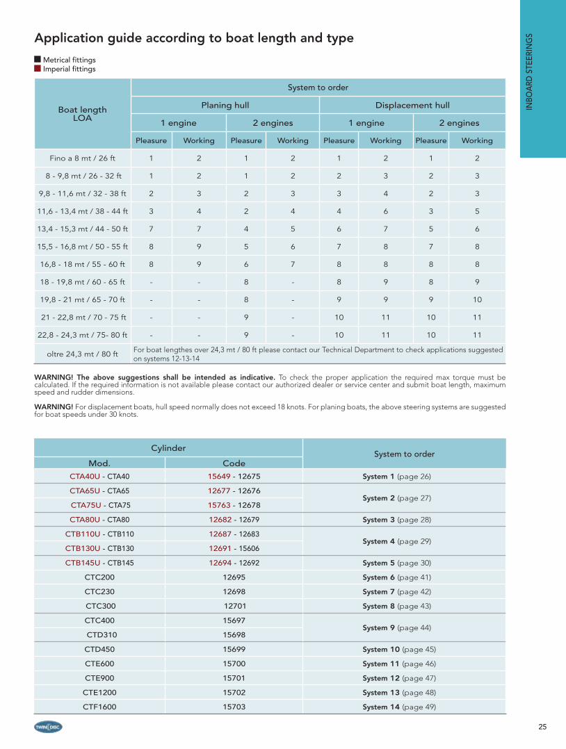
GSApplication guide according to boat length and type
WARNING! The above suggestions shall be intended as indicative. To check the proper application the required max torque must be calculated. If the required information is not available please contact our authorized dealer or service center and submit boat length, maximum speed and rudder dimensions.
WARNING! For displacement boats, hull speed normally does not exceed 18 knots. For planing boats, the above steering systems are suggested for boat speeds under 30 knots.
Boat lengthLOA
System to order
Planing hull Displacement hull
1 engine 2 engines 1 engine 2 engines
Pleasure Working Pleasure Working Pleasure Working Pleasure Working
Fino a 8 mt / 26 ft 1 2 1 2 1 2 1 2
8 - 9,8 mt / 26 - 32 ft 1 2 1 2 2 3 2 3
9,8 - 11,6 mt / 32 - 38 ft 2 3 2 3 3 4 2 3
11,6 - 13,4 mt / 38 - 44 ft 3 4 2 4 4 6 3 5
13,4 - 15,3 mt / 44 - 50 ft 7 7 4 5 6 7 5 6
15,5 - 16,8 mt / 50 - 55 ft 8 9 5 6 7 8 7 8
16,8 - 18 mt / 55 - 60 ft 8 9 6 7 8 8 8 8
18 - 19,8 mt / 60 - 65 ft - - 8 - 8 9 8 9
19,8 - 21 mt / 65 - 70 ft - - 8 - 9 9 9 10
21 - 22,8 mt / 70 - 75 ft - - 9 - 10 11 10 11
22,8 - 24,3 mt / 75- 80 ft - - 9 - 10 11 10 11
oltre 24,3 mt / 80 ft For boat lengthes over 24,3 mt / 80 ft please contact our Technical Department to check applications suggested on systems 12-13-14
CylinderSystem to order
Mod. Code
CTA40U - CTA40 15649 - 12675 System 1 (page 26)
CTA65U - CTA65 12677 - 12676System 2 (page 27)
CTA75U - CTA75 15763 - 12678
CTA80U - CTA80 12682 - 12679 System 3 (page 28)
CTB110U - CTB110 12687 - 12683System 4 (page 29)
CTB130U - CTB130 12691 - 15606
CTB145U - CTB145 12694 - 12692 System 5 (page 30)
CTC200 12695 System 6 (page 41)
CTC230 12698 System 7 (page 42)
CTC300 12701 System 8 (page 43)
CTC400 15697System 9 (page 44)
CTD310 15698
CTD450 15699 System 10 (page 45)
CTE600 15700 System 11 (page 46)
CTE900 15701 System 12 (page 47)
CTE1200 15702 System 13 (page 48)
CTF1600 15703 System 14 (page 49)
Metrical fittingsImperial fittings

26
INBO
ARD
STEERING
S
ALUMINUM cylinder
Components Model Code Q.ty
Cylinder CTA40U - CTA40 15649 - 12675 1
Helm pump Choose the pump model according to the desired wheel turns number in the table here below 1
Hose kit SH-O... (**) See on pages 74-75 for codes 1
Hydraulic oil VG22 21334 3
By-pass Choose the by-pass model according to the pump-cylinder combination in the table here below 1
In case of additional station add:
Second station helm pump Same pump model as above (see table on page bottom) 1
Second station fi ttings kit 23376 - 23487 1
Hose kit SH-O... (**) See on pages 74-75 for codes 1
Hydraulic oil VG22 21334 1
In case of auto-pilot installation please add:
Auto-pilot power unit Choose auto-pilot power unit model on the Selection Guide on pages 55-58-59 1
Auto-pilot fi ttings kit 23377 - 23489 1
System 1
Rudder torque calculated at the working pressure of 70 bar (1000 psi).(*) For more details, see the basic helm section on page 11 and following and to choose the desired mounting confi guration.(**) See on page 74-75 to choose the model and code of the preferred kit. Flexible hose can be used up to a max length of 15 mt - 45’ between pump and cylinder.
Choose combination between pump and cylinder according to the wished number of wheel turns lock-to-lock.Note: the requested effort on the steering wheel is inversely proportional to the wheel turns number lock-to-lock:• less wheel turns, more effort • more wheel turns, less effort Note: by increasing the wheel diameter, the requested effort is reduced.
HELM PUMP
(*)P20BAP Cod. 21173 P20BA Cod. 16192
(*)P30BAP Cod. 21174P30BA Cod. 16193
(*)P42BAP Cod. 21175 P42BA Cod. 16194
CY
LIN
DE
R
CTA40U - Cod. / Part # 15649CTA40 - Cod. / Part # 12675
No. of wheel turns: 5,8Min. hose size: 5/16” I.D. (**)Tiller: 153 mm - 6,02 inAngle: 35° + 35°Torque: 57,83 Kgm - 5028 lb.in.Min. wheel diam.: 350 mm-13,77 in.By-pass: cod. 23186 - 12216
No. of wheel turns: 3,9Min. hose size: 5/16” I.D. (**)Tiller: 153 mm - 6,02 inAngle: 35° + 35°Torque: 57,83 Kgm - 5028 lb.in.Min. wheel diam.:350 mm-13,77 in.By-pass: cod. 23186 - 12216
Pump-cylinder combinationSteering effort
LIGHT NORMAL HEAVY
Metrical fittings Imperial fittings
27
INBO
ARD
STE
ERIN
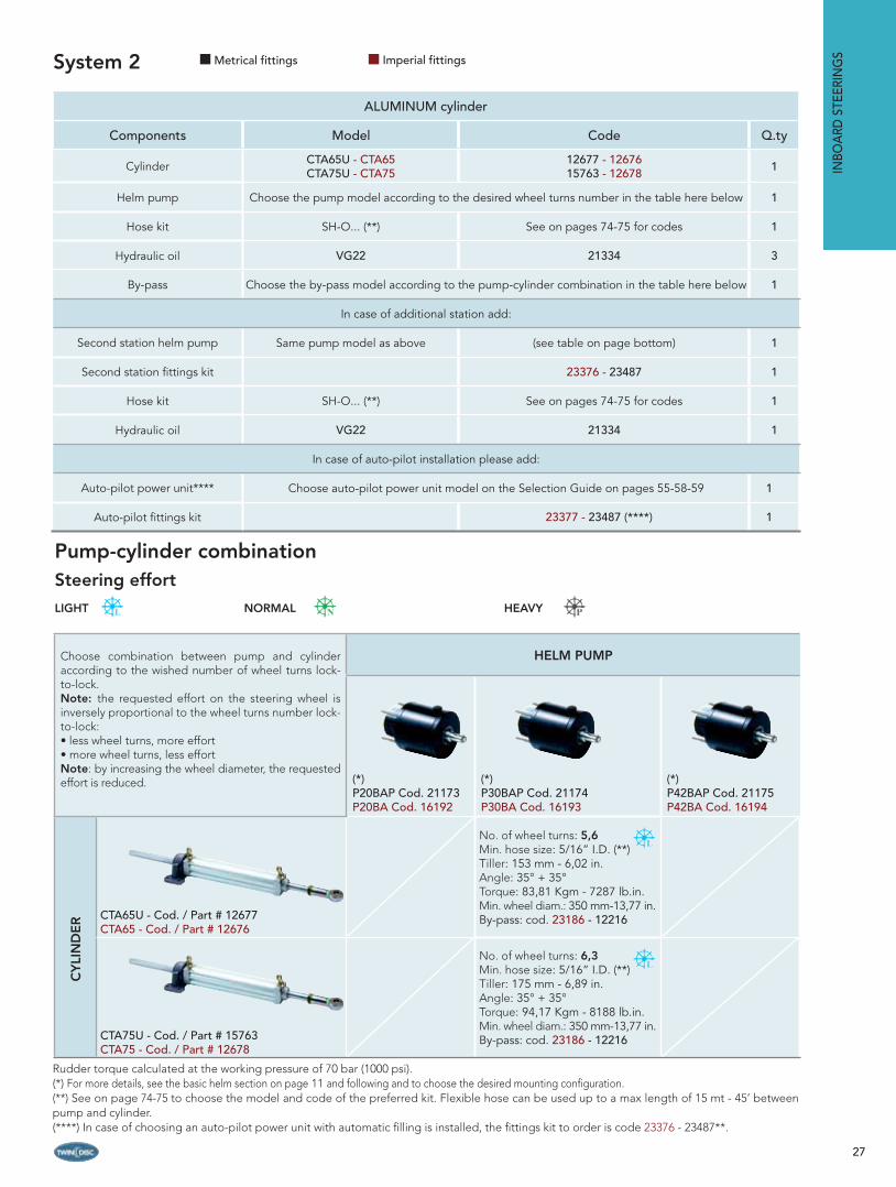
GSSystem 2
ALUMINUM cylinder
Components Model Code Q.ty
Cylinder CTA65U - CTA65CTA75U - CTA75
12677 - 1267615763 - 12678 1
Helm pump Choose the pump model according to the desired wheel turns number in the table here below 1
Hose kit SH-O... (**) See on pages 74-75 for codes 1
Hydraulic oil VG22 21334 3
By-pass Choose the by-pass model according to the pump-cylinder combination in the table here below 1
In case of additional station add:
Second station helm pump Same pump model as above (see table on page bottom) 1
Second station fi ttings kit 23376 - 23487 1
Hose kit SH-O... (**) See on pages 74-75 for codes 1
Hydraulic oil VG22 21334 1
In case of auto-pilot installation please add:
Auto-pilot power unit**** Choose auto-pilot power unit model on the Selection Guide on pages 55-58-59 1
Auto-pilot fi ttings kit 23377 - 23487 (****) 1
Rudder torque calculated at the working pressure of 70 bar (1000 psi).(*) For more details, see the basic helm section on page 11 and following and to choose the desired mounting confi guration.(**) See on page 74-75 to choose the model and code of the preferred kit. Flexible hose can be used up to a max length of 15 mt - 45’ between pump and cylinder.(****) In case of choosing an auto-pilot power unit with automatic fi lling is installed, the fi ttings kit to order is code 23376 - 23487**.
Choose combination between pump and cylinder according to the wished number of wheel turns lock-to-lock.Note: the requested effort on the steering wheel is inversely proportional to the wheel turns number lock-to-lock:• less wheel turns, more effort • more wheel turns, less effort Note: by increasing the wheel diameter, the requested effort is reduced.
HELM PUMP
(*)P20BAP Cod. 21173 P20BA Cod. 16192
(*)P30BAP Cod. 21174P30BA Cod. 16193
(*)P42BAP Cod. 21175 P42BA Cod. 16194
CY
LIN
DE
R CTA65U - Cod. / Part # 12677CTA65 - Cod. / Part # 12676
No. of wheel turns: 5,6Min. hose size: 5/16” I.D. (**)Tiller: 153 mm - 6,02 in.Angle: 35° + 35°Torque: 83,81 Kgm - 7287 lb.in.Min. wheel diam.: 350 mm-13,77 in.By-pass: cod. 23186 - 12216
CTA75U - Cod. / Part # 15763CTA75 - Cod. / Part # 12678
No. of wheel turns: 6,3Min. hose size: 5/16” I.D. (**)Tiller: 175 mm - 6,89 in.Angle: 35° + 35°Torque: 94,17 Kgm - 8188 lb.in.Min. wheel diam.: 350 mm-13,77 in.By-pass: cod. 23186 - 12216
Metrical fittings Imperial fittings
Pump-cylinder combinationSteering effort
LIGHT NORMAL HEAVY
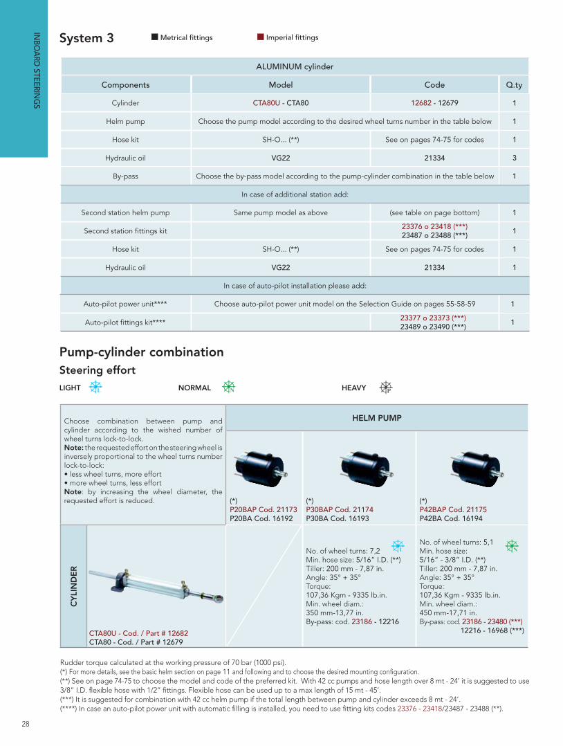
ALUMINUM cylinder
Components Model Code Q.ty
Cylinder CTA80U - CTA80 12682 - 12679 1
Helm pump Choose the pump model according to the desired wheel turns number in the table below 1
Hose kit SH-O... (**) See on pages 74-75 for codes 1
Hydraulic oil VG22 21334 3
By-pass Choose the by-pass model according to the pump-cylinder combination in the table below 1
In case of additional station add:
Second station helm pump Same pump model as above (see table on page bottom) 1
Second station fi ttings kit 23376 o 23418 (***)23487 o 23488 (***) 1
Hose kit SH-O... (**) See on pages 74-75 for codes 1
Hydraulic oil VG22 21334 1
In case of auto-pilot installation please add:
Auto-pilot power unit**** Choose auto-pilot power unit model on the Selection Guide on pages 55-58-59 1
Auto-pilot fi ttings kit**** 23377 o 23373 (***)23489 o 23490 (***)
1
System 3
28
Choose combination between pump and cylinder according to the wished number of wheel turns lock-to-lock.Note: the requested effort on the steering wheel is inversely proportional to the wheel turns number lock-to-lock:• less wheel turns, more effort • more wheel turns, less effort Note: by increasing the wheel diameter, the requested effort is reduced.
HELM PUMP
(*)P20BAP Cod. 21173 P20BA Cod. 16192
(*)P30BAP Cod. 21174P30BA Cod. 16193
(*)P42BAP Cod. 21175 P42BA Cod. 16194
C
YLI
ND
ER
CTA80U - Cod. / Part # 12682CTA80 - Cod. / Part # 12679
No. of wheel turns: 7,2Min. hose size: 5/16” I.D. (**)Tiller: 200 mm - 7,87 in.Angle: 35° + 35°Torque: 107,36 Kgm - 9335 lb.in.Min. wheel diam.: 350 mm-13,77 in.By-pass: cod. 23186 - 12216
No. of wheel turns: 5,1Min. hose size: 5/16” - 3/8” I.D. (**)Tiller: 200 mm - 7,87 in.Angle: 35° + 35°Torque: 107,36 Kgm - 9335 lb.in.Min. wheel diam.: 450 mm-17,71 in.By-pass: cod. 23186 - 23480 (***) 12216 - 16968 (***)
INBO
ARD
STEERING
S
Rudder torque calculated at the working pressure of 70 bar (1000 psi).(*) For more details, see the basic helm section on page 11 and following and to choose the desired mounting confi guration.(**) See on page 74-75 to choose the model and code of the preferred kit. With 42 cc pumps and hose length over 8 mt - 24’ it is suggested to use 3/8” I.D. fl exible hose with 1/2” fi ttings. Flexible hose can be used up to a max length of 15 mt - 45’.(***) It is suggested for combination with 42 cc helm pump if the total length between pump and cylinder exceeds 8 mt - 24’. (****) In case an auto-pilot power unit with automatic fi lling is installed, you need to use fi tting kits codes 23376 - 23418/23487 - 23488 (**).
Metrical fittings Imperial fittings
Pump-cylinder combinationSteering effort
LIGHT NORMAL HEAVY

BRASS cylinder
Components Model Code Q.ty
CylinderCTB110U - CTB130U 12687 - 12691
1CTB110 - CTB130 12683 - 15606
Helm pump Choose the pump model according to the desired wheel turns number in the table below 1
Hose kit SH-O... (**) See on pages 74-75 for codes 1
Hydraulic oil VG22 21334 3
By-pass Choose the by-pass model according to the pump-cylinder combination in the table below 1
In case of additional station add:
Second station helm pump Same pump model as above (see table on page bottom) 1
Second station fi ttings kit 23376 o 23418 (***)23487 o 23488 (***) 1
Hose kit SH-O... (**) See on pages 74-75 for codes 1
Hydraulic oil VG22 23377 o 23373 (***)23489 o 23490 (***) 1
In case of auto-pilot installation please add:
Auto-pilot power unit**** Choose auto-pilot power unit model on the Selection Guide on pages 55-58-59 1
Auto-pilot fi ttings kit 23373 (****) - 23490 (***) 1
System 4
29
Choose combination between pump and cylinder according to the wished number of wheel turns lock-to-lock.Note: the requested effort on the steering wheel is inversely proportional to the wheel turns number lock-to-lock: less wheel turns, more effort - more wheel turns, less effort.Note: by increasing the wheel diameter, therequested effort is reduced.
HELM PUMP
(*)P20BAP Cod. 21173 P20BA Cod. 16192
(*)P30BAP Cod. 21174P30BA Cod. 16193
(*)P42BAP Cod. 21175 P42BA Cod. 16194
CY
LIN
DE
R CTB110U - Cod. / Part # 12687CTB110 - Cod. / Part # 12683
No. of wheel turns: 6,7Min. hose size: 3/8” I.D. (**)Tiller: 153 mm - 6,02 in.Angle: 35° + 35°Torque: 140,85 Kgm - 12247 lb.in.Min. wheel diam.: 450 mm-17,71 in.By-pass: cod. 23186 - 23480 (***) 12216 - 16968 (***)
CTB130U - Cod. / Part # 12691CTB130 - Cod. / Part # 15606
No. of wheel turns: 7,7Min. hose size: 3/8” I.D. (**)Tiller: 180 mm - 7 in.Angle: 35° + 35°Torque: 140,85 Kgm - 12247 lb.in.Min. wheel diam.: 450 mm-17,71 in.By-pass: cod. 23186 - 23480 (***) 12216 - 16968 (***)
Rudder torque calculated at the working pressure of 70 bar (1000 psi).(*) For more details, see the basic helm section on page 11 and following and to choose the desired mounting confi guration.(**) See on page 74-75 to choose the model and code of the preferred kit. With 42 cc pumps and hose length over 8 mt - 24’ it is suggested to use 3/8” I.D. fl exible hose with 1/2” fi ttings. Flexible hose can be used up to a max length of 15 mt - 45’.(***) It is suggested for combination with 42 cc helm pump if the total length between pump and cylinder exceeds 8 mt - 24’. (****) In case an auto-pilot power unit with automatic fi lling is installed, you need to use fi tting kits codes 23376 - 23418/23487 - 23488 (**).
INBO
ARD
STE
ERIN
GSMetrical fittings Imperial fittings
Pump-cylinder combinationSteering effort
LIGHT NORMAL HEAVY
30
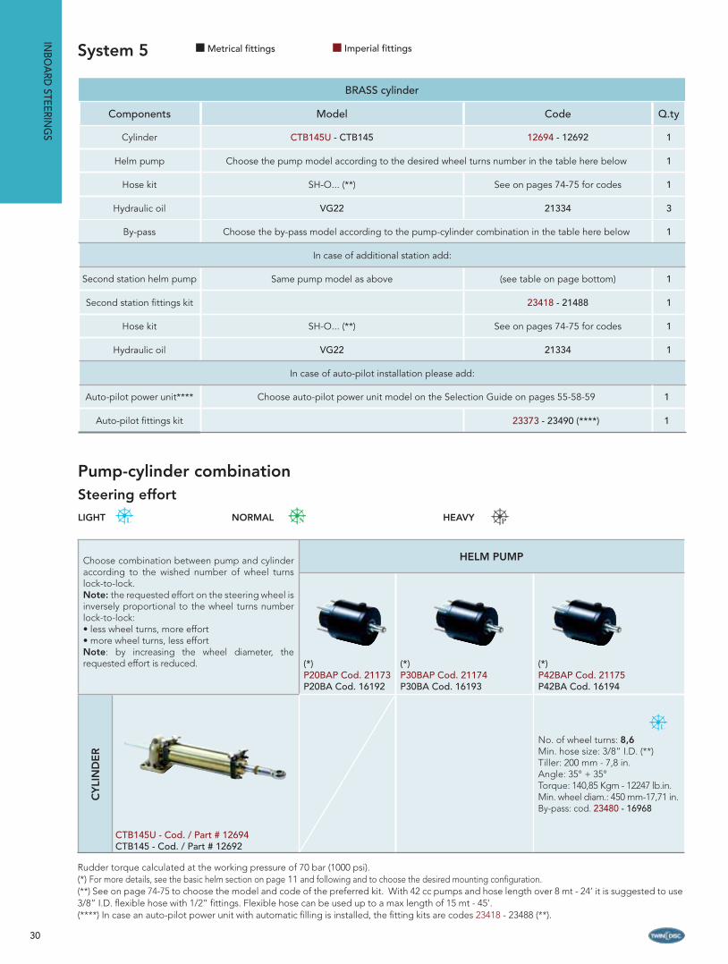
BRASS cylinder
Components Model Code Q.ty
Cylinder CTB145U - CTB145 12694 - 12692 1
Helm pump Choose the pump model according to the desired wheel turns number in the table here below 1
Hose kit SH-O... (**) See on pages 74-75 for codes 1
Hydraulic oil VG22 21334 3
By-pass Choose the by-pass model according to the pump-cylinder combination in the table here below 1
In case of additional station add:
Second station helm pump Same pump model as above (see table on page bottom) 1
Second station fi ttings kit 23418 - 21488 1
Hose kit SH-O... (**) See on pages 74-75 for codes 1
Hydraulic oil VG22 21334 1
In case of auto-pilot installation please add:
Auto-pilot power unit**** Choose auto-pilot power unit model on the Selection Guide on pages 55-58-59 1
Auto-pilot fi ttings kit 23373 - 23490 (****) 1
System 5
Rudder torque calculated at the working pressure of 70 bar (1000 psi).(*) For more details, see the basic helm section on page 11 and following and to choose the desired mounting confi guration.(**) See on page 74-75 to choose the model and code of the preferred kit. With 42 cc pumps and hose length over 8 mt - 24’ it is suggested to use 3/8” I.D. fl exible hose with 1/2” fi ttings. Flexible hose can be used up to a max length of 15 mt - 45’.(****) In case an auto-pilot power unit with automatic fi lling is installed, the fi tting kits are codes 23418 - 23488 (**).
INBO
ARD
STEERING
S
Choose combination between pump and cylinder according to the wished number of wheel turns lock-to-lock.Note: the requested effort on the steering wheel is inversely proportional to the wheel turns number lock-to-lock:• less wheel turns, more effort • more wheel turns, less effort Note: by increasing the wheel diameter, therequested effort is reduced.
HELM PUMP
(*)P20BAP Cod. 21173 P20BA Cod. 16192
(*)P30BAP Cod. 21174P30BA Cod. 16193
(*)P42BAP Cod. 21175 P42BA Cod. 16194
C
YLI
ND
ER
CTB145U - Cod. / Part # 12694CTB145 - Cod. / Part # 12692
No. of wheel turns: 8,6Min. hose size: 3/8” I.D. (**)Tiller: 200 mm - 7,8 in.Angle: 35° + 35°Torque: 140,85 Kgm - 12247 lb.in.Min. wheel diam.: 450 mm-17,71 in.By-pass: cod. 23480 - 16968
Metrical fittings Imperial fittings
Pump-cylinder combinationSteering effort
LIGHT NORMAL HEAVY

31
B C
H
F
G
A
QE
D
R
35° 35°
NL
P M
S
Dimensions
Model Stroke A B C D E F G H L M N P Q R S
CTA40UCTA40
178 mm 555 mm 459 mm 96 mm 14 mm 19,05 mm 35 mm 86 mm 298 mm 62 mm 90 mm 40 mm 73 mm 8,5 mm 153 mm 127 mm
7.0 in. 21.85 in. 18 in. 3.78 in 0.55 in. 3/4 in. 1.38 in. 3.39 in. 11.73 in. 2.44 in. 3.54 in. 1.57 in. 2.87 in. 0.33 in. 6.0 in. 5.0 in.
CTA65UCTA65
178 mm 586 mm 495 mm 91 mm 20 mm 19,05 mm 40 mm 91 mm 305 mm 60 mm 125 mm 40 mm 105 mm 8,5 mm 153 mm 127 mm
7.0 in. 23 in. 19.49 in. 3.58 in. 0.79 in. 3/4 in. 1.57 in. 3.58 in. 12.0 in. 2.36 in. 4.92 in. 1.57 in. 4.13 in. 0.33 in. 6.0 in. 5.0 in.
CTA75UCTA75
200 mm 630 mm 528 mm 102 mm 20 mm 19,05 mm 40 mm 91 mm 327 mm 60 mm 125 mm 40 mm 105 mm 8,5 mm 175 mm 143 mm
7.87 in. 24.8 in. 20.79 in. 4.0 in. 0.79 in. 3/4 in. 1.57 in. 3.58 in. 12.87 in. 2.36 in. 4.92 in. 1.57 in. 4.13 in. 0.33 in. 6.89 in. 5.6 in.
CTA80UCTA80
228 mm 690 mm 573 mm 117 mm 20 mm 19,05 mm 40 mm 91 mm 355 mm 60 mm 125 mm 40 mm 105 mm 8,5 mm 200 mm 164 mm
9.0 in. 27.16 in. 22.56 in. 4.61 in. 0.79 in. 3/4 in. 1.57 in. 3.58 in. 13.98 in. 2.36 in. 4.92 in. 1.57 in. 4.13 in. 0.33 in. 7.87 in. 6.5 in.
Technical specifi cations
Inboard steering cylinders Series CTA
INBO
ARD
STE
ERIN
GS
Main features
Cylinder body in anodized aluminumPiston rod in stainless steel for a high corrosion resistanceAdjustable base either horizontally or verticallyAvailable in a range of volumes between 115 to 215 ccSupplied with bleedersMeet ABYC standards
Technical specifi cations
Model Code Stroke Torque Thrust at 70 bar1000 psi Volume Tiller Angle Fittings Weight
CTA40U 15649 178 mm 57.83 Kgm 455 Kgf 115.7 cc 153 mm35°+35°
1/4” NPTF - 3/8” D.E. 2,2 Kg
CTA40 12675 7.0 in 5008 lb.in. 1002 lbf 7.1 cu.in 6 in. G1/4” - hose d. 10 4,85 lb
CTA65U 12677 178 mm 83.81 Kgm 659.4 Kgf 167.68 cc 153 mm35°+35°
1/4” NPTF - 3/8” D.E. 2,6 Kg
CTA65 12676 7.0 in 7257 lb.in. 1453 lbf 10.23 cu.in 6 in. G1/4” - hose d. 10 5,73 lb
CTA75U 15763 200 mm 94.17 Kgm 659.4 Kgf 188.4 cc 175 mm35°+35°
1/4” NPTF - 3/8” D.E. 3,0 Kg
CTA75 12678 7.78 in 8155 lb.in. 1453 lbf 11.5 cu.in 6.9 in. G1/4” - hose d. 10 6,61 lb
CTA80U 12682 228 mm 107.36 Kgm 659.4 Kgf 214.78 cc 200 mm35°+35°
1/4” NPTF - 3/8” D.E. 3,2 Kg
CTA80 12679 9.0 in 9297 lb.in. 1453 lbf 13.11 cu.in 7.8 in. G1/4” - hose d. 10 7,05 lb
Note: the inboard cylinders mod. CTA are not suitable for installations on racing boats.
Metrical fittings Imperial fittings
32
B C
G
F
H
R
E
35° 35°
D
A
Q
NL
M
S
P
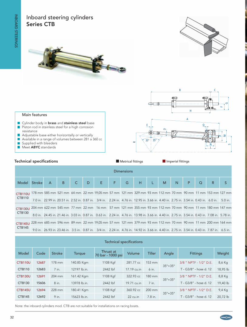
Technical specifi cations
Model Code Stroke Torque Thrust at 70 bar - 1000 psi Volume Tiller Angle Fittings Weight
CTB110U 12687 178 mm 140.85 Kgm 1108 Kgf 281.77 cc 153 mm35°+35°
3/8 ” NPTF - 1/2” D.E. 8,6 Kg
CTB110 12683 7 in. 12197 lb.in. 2442 lbf 17.19 cu.in 6 in. T - G3/8” - hose d. 12 18,95 lb
CTB130U 12691 204 mm 161.42 Kgm 1108 Kgf 322.93 cc 180 mm35°+35°
3/8 ” NPTF - 1/2” D.E. 8,8 Kg
CTB130 15606 8 in. 13978 lb.in. 2442 lbf 19.71 cu.in 7 in. T - G3/8” - hose d. 12 19,40 lb
CTB145U 12694 228 mm 180.41 Kgm 1108 Kgf 360.92 cc 200 mm35°+35°
3/8 ” NPTF - 1/2” D.E. 9,4 Kg
CTB145 12692 9 in. 15623 lb.in. 2442 lbf 22 cu.in 7.8 in. T - G3/8” - hose d. 12 20,72 lb
Note: the inboard cylinders mod. CTB are not suitable for installations on racing boats.
Dimensions
Model Stroke A B C D E F G H L M N P Q R S
CTB110UCTB110
178 mm 585 mm 521 mm 64 mm 22 mm 19,05 mm 57 mm 121 mm 329 mm 93 mm 112 mm 70 mm 90 mm 11 mm 153 mm 127 mm
7.0 in. 22.99 in. 20.51 in. 2.52 in. 0.87 in. 3/4 in. 2.24 in. 4.76 in. 12.95 in. 3.66 in. 4.40 in. 2.75 in. 3.54 in. 0.43 in. 6.0 in. 5.0 in.
CTB130UCTB130
204 mm 622 mm 545 mm 77 mm 22 mm 16 mm 57 mm 121 mm 355 mm 93 mm 112 mm 70 mm 90 mm 11 mm 180 mm 147 mm
8.0 in. 24.45 in. 21.46 in. 3.03 in. 0.87 in. 0.63 in. 2.24 in. 4.76 in. 13.98 in. 3.66 in. 4.40 in. 2.75 in. 3.54 in. 0.43 in. 7.08 in. 5.78 in.
CTB145UCTB145
228 mm 685 mm 596 mm 89 mm 22 mm 19,05 mm 57 mm 121 mm 379 mm 93 mm 112 mm 70 mm 90 mm 11 mm 200 mm 164 mm
9.0 in. 26.93 in. 23.46 in. 3.5 in. 0.87 in. 3/4 in. 2.24 in. 4.76 in. 14.92 in. 3.66 in. 4.40 in. 2.75 in. 3.54 in. 0.43 in. 7.87 in. 6.5 in.
Technical specifi cations
Inboard steering cylinders Series CTB
INBO
ARD
STEERING
S
Main features
Cylinder body in brass and stainless steel basePiston rod in stainless steel for a high corrosion resistanceAdjustable base either horizontally or verticallyAvailable in a range of volumes between 281 a 360 ccSupplied with bleedersMeet ABYC standards
Metrical fittings Imperial fittings

33

34
By-pass non return valve
Cross relief valve
Non return valve
Cross relief valve
INBO
ARD
STEERING
SH
EAVY DU
TY
35
INBO
ARD
STE
ERIN
GS
HEA
VY D
UTY
HEAVY DUTY INBOARD STEERING SYSTEMS
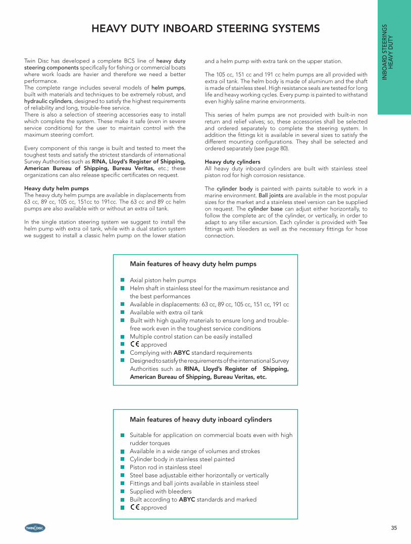
Twin Disc has developed a complete BCS line of heavy duty steering components specifi cally for fi shing or commercial boats where work loads are havier and therefore we need a better performance.The complete range includes several models of helm pumps, built with materials and techniques to be extremely robust, and hydraulic cylinders, designed to satisfy the highest requirements of reliability and long, trouble-free service.There is also a selection of steering accessories easy to install which complete the system. These make it safe (even in severe service conditions) for the user to maintain control with the maximum steering comfort.
Every component of this range is built and tested to meet the toughest tests and satisfy the strictest standards of international Survey Authorities such as RINA, Lloyd’s Register of Shipping, American Bureau of Shipping, Bureau Veritas, etc.; these organizations can also release specifi c certifi cates on request.
Heavy duty helm pumpsThe heavy duty helm pumps are available in displacements from 63 cc, 89 cc, 105 cc, 151cc to 191cc. The 63 cc and 89 cc helm pumps are also available with or without an extra oil tank.
In the single station steering system we suggest to install the helm pump with extra oil tank, while with a dual station system we suggest to install a classic helm pump on the lower station
and a helm pump with extra tank on the upper station.
The 105 cc, 151 cc and 191 cc helm pumps are all provided with extra oil tank. The helm body is made of aluminum and the shaft is made of stainless steel. High resistance seals are tested for long life and heavy working cycles. Every pump is painted to withstand even highly saline marine environments.
This series of helm pumps are not provided with built-in non return and relief valves; so, these accessories shall be selected and ordered separately to complete the steering system. In addition the fi ttings kit is available in several sizes to satisfy the different mounting confi gurations. They shall be selected and ordered separately (see page 80).
Heavy duty cylindersAll heavy duty inboard cylinders are built with stainless steel piston rod for high corrosion resistance.
The cylinder body is painted with paints suitable to work in a marine environment. Ball joints are available in the most popular sizes for the market and a stainless steel version can be supplied on request. The cylinder base can adjust either horizontally, to follow the complete arc of the cylinder, or vertically, in order to adapt to any tiller excursion. Each cylinder is provided with Tee fi ttings with bleeders as well as the necessary fi ttings for hose connection.
Main features of heavy duty helm pumps
Axial piston helm pumpsHelm shaft in stainless steel for the maximum resistance and the best performancesAvailable in displacements: 63 cc, 89 cc, 105 cc, 151 cc, 191 cc Available with extra oil tankBuilt with high quality materials to ensure long and trouble-free work even in the toughest service conditionsMultiple control station can be easily installed approved Complying with ABYC standard requirementsDesigned to satisfy the requirements of the international Survey Authorities such as RINA, Lloyd’s Register of Shipping, American Bureau of Shipping, Bureau Veritas, etc.
Main features of heavy duty inboard cylinders
Suitable for application on commercial boats even with high rudder torquesAvailable in a wide range of volumes and strokes Cylinder body in stainless steel paintedPiston rod in stainless steelSteel base adjustable either horizontally or verticallyFittings and ball joints available in stainless steelSupplied with bleedersBuilt according to ABYC standards and marked approved
36
HELM
PUM
PSH
EAVY DU
TY
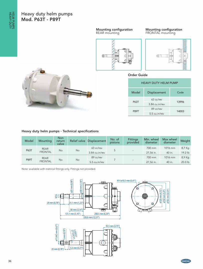
HEAVY DUTY HELM PUMP
Model Displacement Code
P63T63 cc/rev
139963.84 cu.in/rev
P89T89 cc/rev
140035.5 cu.in/rev
Model MountingNon
return valve
Relief valve Displacement No. of pistons
Fittings provided
Min. wheel diameter
Max wheel diameter Weight
P63T REAR FRONTAL No No
63 cc/rev5 -
700 mm 1016 mm 8,7 Kg
3.84 cu.in/rev 27,56 in. 40 in. 19.2 lb
P89T REAR FRONTAL No No
89 cc/rev7 -
700 mm 1016 mm 8,9 Kg
5.5 cu.in/rev 27,56 in. 40 in. 20.0 lb
Note: available with metrical fi ttings only. Fittings not provided.
Heavy duty helm pumps - Technical specifications
Heavy duty helm pumpsMod. P63T - P89T
N°4 ø10,5 mm (0,41”)
ø120
mm
(4,7
2”)
ø150
mm
(5,9
”)
ø166
mm
(6,5
3”)
20 mm (0,78”) 31,1 mm (1,22”)
80 mm (3,14”)
ø30
mm
(1,1
8”)
ø25
mm
(0,9
8”)
M16
131,1 mm (5,16°) 208,5 mm (8,20”)339,6 mm (13,37”)
20 mm (0,78”) 5,5 mm (0,21”)
ø17,
042
mm
(0,6
7”)
5 m
m (0
,19”
) 2,35972°(2°23’9,5”)
95,5 mm (3,75”)
Mounting configurationREAR mounting
Mounting configurationFRONTAL mounting
Order Guide

37
Model MountingNon
return valve
Relief valve Displacement No. of pistons
Fittings provided
Min. wheel diameter
Max wheel diameter Weight
P63S REAR FRONTAL No No
63 cc/rev5 -
700 mm 1016 mm 9,3 Kg
3.84 cu.in/rev 27,56 in. 40 in. 20.5 lb
P89S REAR FRONTAL No No
89 cc/rev7 -
700 mm 1016 mm 9,5 Kg
5.5 cu.in/rev 27,56 in. 40 in. 21.0 lb
Note: available with metrical fi ttings only. Fittings not provided
Heavy duty helm pumpsMod. P63S - P89S with oil tank
Heavy duty helm pumps with oil tank - Technical specifications
HEAVY DUTY HELM PUMP
Model Displacement Code
P63S 63 cc/rev
139953.84 cu.in/rev
P89S89 cc/rev
140025.5 cu.in/rev
140 mm (5,51”)
N°4 ø10,5 mm(0,41”)
135
mm
(5,3
1”)
ø120
mm
(4,7
2”)
ø150
mm
(5,9
”)
110 mm (4,33”)
ø30
mm
(1,1
8”)
ø25
mm
(0,9
8”)
M16
20 mm (0,78”)31,1 mm(1,22”)80 mm(3,14”)
131,1 mm (5,16”) 208,5 mm (8,20”)339,6 mm (13,37”)
20 mm (0,78”)5,5 mm (0,21”)
ø17,
042
mm
(0,6
7”)
5 m
m (0
,19”
) 2,35972°
(2°23’9,5”)
Mounting configurationREAR mounting
Mounting configurationFRONTAL mounting
HEL
M P
UM
PSH
EAVY
DU
TY
Order Guide

38
Model MountingNon
return valve
Relief valve Displace-ment
No. of pistons
Fittings provided
Min. wheel diameter
Max wheel diameter Weight
P105 REAR No No105 cc/rev
5G1/2”
18 mm D.E.1000 mm 1220 mm 21,5 Kg
6,4 cu.in/rev 39,37 in. 48 in. 47,39 lb
P151 REAR No No151 cc/rev
7G1/2”
18 mm D.E. 1000 mm 1220 mm 23,2 Kg
9,2 cu.in/rev 39,37 in. 48 in. 51,14 lb
P191 REAR No No191 cc/rev
7G1/2”
18 mm D.E.1000 mm 1220 mm 24,5 Kg
11,7 cu.in/rev 39,37 in. 48 in. 54,00 lb
Note: available with metrical fi ttings only. Fittings provided.
Heavy duty helm pumpsMod. P105 - P151 - P191 with oil tank
Heavy duty helm pumps with oil tank - Technical specifications
196 mm (7,72”)
164 mm (6,46”)
70 mm(2,76”)
280 mm (11”)
198 mm (7,8”)
158 mm (6,22”)
40 mm(1,57”) 12 mm
(0,04”)
76 mm(3”)
161 mm (6,34”)196 mm (7,72”)
166 mm (6,54”)
5 mm(0,2”)
5 mm(0,2”)
40 mm(1,57”)
50 mm(1,97”)
76 mm(2,99”)
70 mm (2,76”)
20 mm(0,79”) 4,5 mm
(0,18”)
ø100 mm(3,94”)
145
mm
(5,7
”)
ø35
mm
(1,3
8”) ø12,5 mm
(0,5”)
161
mm
(6,3
4”)
196
mm
(7,7
2”)
ø35
mn
(1,3
8”)
10 m
m (0
,39”
)
ø30
mm
(1,1
8”)
M22
x1,5
Mounting configurationFRONTAL mounting
HEAVY DUTY HELM PUMP
Model Displacement Code
P105 105 cc/rev
140526,4 cu.in/rev
P151151 cc/rev
140829,2 cu.in/rev
P191191cc/rev
1408411,7 cu.in/rev
HELM
PUM
PSH
EAVY DU
TY
Order Guide

39

40
Order Guide
CylinderSystem to order
Model Code
CTC200 12695 System 6 (page 41)
CTC230 12698 System 7 (page 42)
CTC300 12701 System 8 (page 43)
CTC400 15697System 9 (page 44)
CTD310 15698
CTD450 15699 System 10 (page 45)
CTE600 15700 System 11 (page 46)
CTE900 15701 System 12 (page 47)
CTE1200 15702 System 13 (page 48)
CTF1600 15703 System 14 (page 49)
Boat length LOA
System to order
Planing hull Displacement hull
1 engine 2 engines 1 engine 2 engines
Pleasure Working Pleasure Working Pleasure Working Pleasure Working
11,6 - 13,4 mt / 38 - 44 ft 3 4 3 4 4 6 3 5
13,4 - 15,3 mt / 44 - 50 ft 7 7 4 5 6 7 5 6
15,5 - 16,8 mt / 50 - 55 ft 8 9 5 6 7 8 7 8
16,8 - 18 mt / 55 - 60 ft 8 9 6 7 8 8 8 8
18 - 19,8 mt / 60 - 65 ft - - 8 - 8 9 8 9
19,8 - 21 mt / 65 - 70 ft - - 8 - 9 9 9 10
21 - 22,8 mt / 70 - 75 ft - - 9 - 10 11 10 11
22,8 - 24,3 mt / 75- 80 ft - - 9 - 10 11 10 11
oltre 24,3 mt / 80 ft For boat lengthes over 24,3 mt/ 80 ft please contact our technical department to check applications suggested on systems 12-13-14
WARNING! The above suggestions shall be intended as indicative. To check the proper application the required max torque must be calculated. If the required information is not available please contact our authorized dealer or service center and submit boat length, maximum speed and rudder dimensions.
WARNING! For displacement boats, hull speed normally does not exceed 18 knots. For planing boats, the above steering systems are suggested for boat speeds under 30 knots.
INBO
ARD
STEERING
SH
EAVY DU
TY

41
INBO
ARD
STE
ERIN
GS
HEA
VY D
UTY
SINGLE-station steering system DOUBLE-station steering system
Components Model Code Q.ty Components Model Code Q.ty
Cylinder CTC200 12695 1 Cylinder CTC200 12695 1
Flexible hoses for cylinder Included - 2 Flexible hoses for cylinder Included - 2
Main station pump P63S 13995 1 Main station pump P63T 13996 1
Second station pump - - - Second station pump P63S 13995 1
Pump fi ttings kit14359
o 14360**
2 Pump fi ttings kit23492
o 23493**
1
Suggested min. hose size
Copper tube d.e.12 x 1 mmCopper tube d.e. 14 x 1 mm** - - Suggested min. hose size Copper tube d.e.12 x 1 mm
Copper tube d.e. 14 x 1 mm** - -
Hydraulic oil VG22 21334 4 Hydraulic oil VG22 21334 4
See on page bottom for by-pass and valve selection according to pump type and tube length
In case of auto-pilot installation please add:
Auto-pilot power unitChoose auto-pilot power unit model on the selection guides
on pages 55-58-591 Auto-pilot power unit
Choose auto-pilot power unit model on the selection guides on pages 55-58-59
1
Pump No. of stations
Kit fi ttings code Valve and by-pass codeType and length of copper tube
between pump and cylinder<15 mt - 45’ >15 mt - 45’
Non return valve
Relief valve
Non return valve
by-pass
Manual by-pass
P63
1 14359 x 2 q.ty 23500 15707 Copper tube d.e. 12 x 1 mm <15 mt - 45’
1 14360 x 2 q.ty 23501 17672 Copper tube d.e. 14 x 1 mm >15 mt - 45’
2 23492 15708 23500 16968 Copper tube d.e. 12 x 1 mm <15 mt - 45’
2 23493 23513 23501 12134 Copper tube d.e. 14 x 1 mm >15 mt - 45’
For additional information on the fi ttings kit see the section on page 74-75
System 6
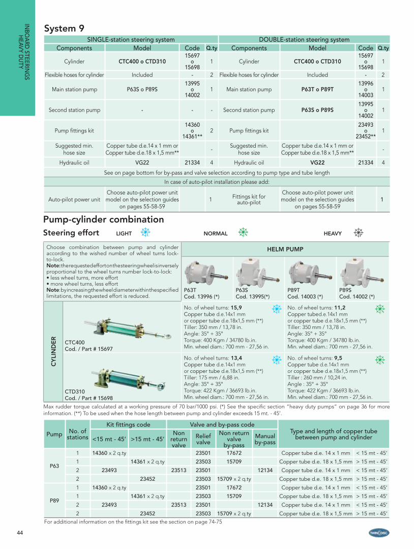
Max rudder torque calculated at a working pressure of 70 bar/1000 psi. (*) See the specifi c section “heavy duty pumps” on page 36 for more information. (**) To be used when the hose length between pump and cylinder exceeds 15 mt. - 45’.
Choose combination between pump and cylinder according to the wished number of wheel turns lock-to-lock.Note: the requested effort on the steering wheel is inversely proportional to the wheel turns number lock-to-lock:• less wheel turns, more effort • more wheel turns, less effort Note: by increasing the wheel diameter, the requested effort is reduced.
HELM PUMP
P63TCod. 13996 (*)
P63SCod. 13995 (*)
CY
LIN
DE
R
CTC200Cod. / Part # 12695
No. of wheel turns: 7,9Min. hose size: copper tube d.e.12 x 1 mm or copper tube d.e. 14 x 1 mm (**) Tiller: 175 mm / 6.9 in.Angle: 35° + 35°Torque: 249,93 Kgm / 21643 lb.in.Min. wheel diam.: 700 mm - 27,56 in.
Pump-cylinder combinationSteering effort
LIGHT NORMAL HEAVY
42
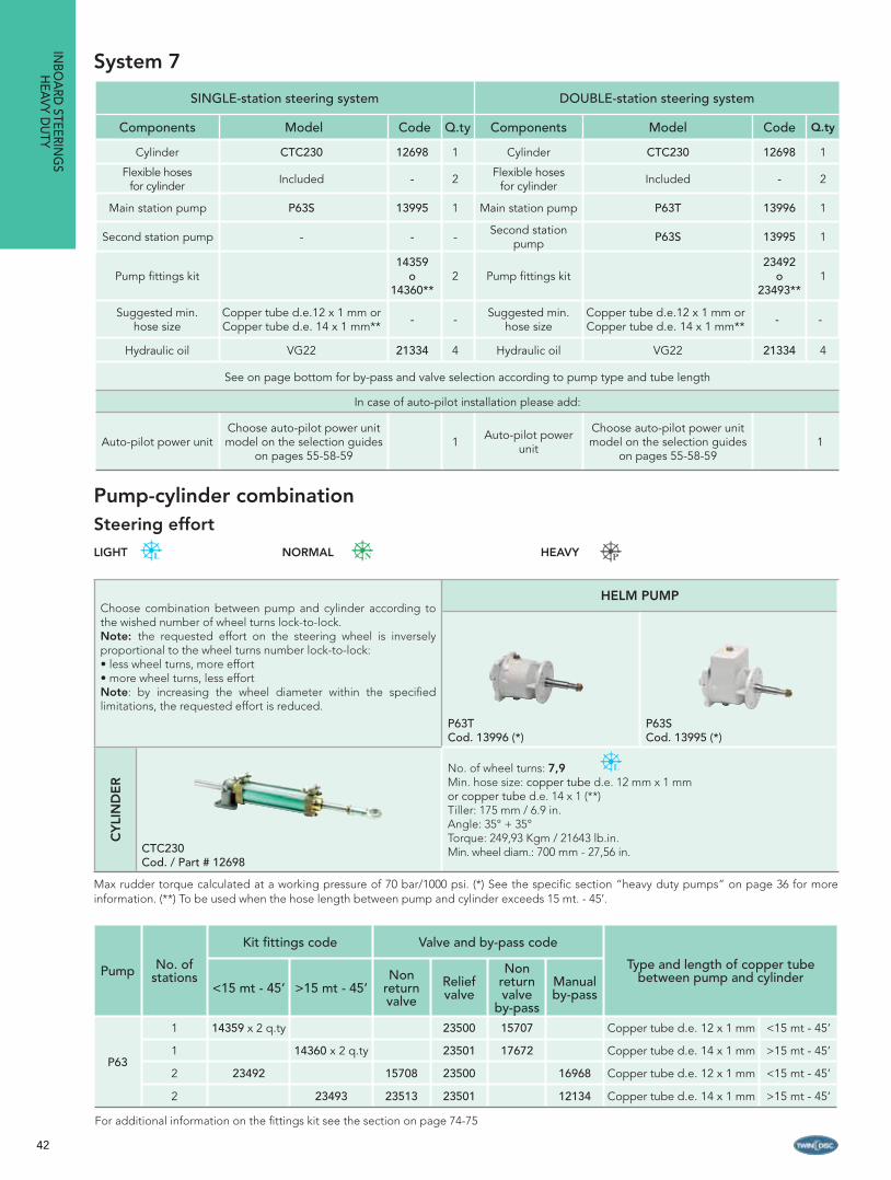
System 7
SINGLE-station steering system DOUBLE-station steering system
Components Model Code Q.ty Components Model Code Q.ty
Cylinder CTC230 12698 1 Cylinder CTC230 12698 1
Flexible hoses for cylinder Included - 2 Flexible hoses
for cylinder Included - 2
Main station pump P63S 13995 1 Main station pump P63T 13996 1
Second station pump - - - Second station pump P63S 13995 1
Pump fi ttings kit14359
o 14360**
2 Pump fi ttings kit23492
o 23493**
1
Suggested min. hose size
Copper tube d.e.12 x 1 mm orCopper tube d.e. 14 x 1 mm** - - Suggested min.
hose sizeCopper tube d.e.12 x 1 mm orCopper tube d.e. 14 x 1 mm** - -
Hydraulic oil VG22 21334 4 Hydraulic oil VG22 21334 4
See on page bottom for by-pass and valve selection according to pump type and tube length
In case of auto-pilot installation please add:
Auto-pilot power unitChoose auto-pilot power unit model on the selection guides
on pages 55-58-591 Auto-pilot power
unit
Choose auto-pilot power unit model on the selection guides
on pages 55-58-591
Pump No. of stations
Kit fi ttings code Valve and by-pass code
Type and length of copper tube between pump and cylinder
<15 mt - 45’ >15 mt - 45’Non
return valve
Relief valve
Non return valve
by-pass
Manual by-pass
P63
1 14359 x 2 q.ty 23500 15707 Copper tube d.e. 12 x 1 mm <15 mt - 45’
1 14360 x 2 q.ty 23501 17672 Copper tube d.e. 14 x 1 mm >15 mt - 45’
2 23492 15708 23500 16968 Copper tube d.e. 12 x 1 mm <15 mt - 45’
2 23493 23513 23501 12134 Copper tube d.e. 14 x 1 mm >15 mt - 45’
For additional information on the fi ttings kit see the section on page 74-75
INBO
ARD
STEERING
SH
EAVY DU
TY
Choose combination between pump and cylinder according to the wished number of wheel turns lock-to-lock.Note: the requested effort on the steering wheel is inversely proportional to the wheel turns number lock-to-lock:• less wheel turns, more effort • more wheel turns, less effort Note: by increasing the wheel diameter within the specifi ed limitations, the requested effort is reduced.
HELM PUMP
P63TCod. 13996 (*)
P63SCod. 13995 (*)
CY
LIN
DE
R
CTC230Cod. / Part # 12698
No. of wheel turns: 7,9Min. hose size: copper tube d.e. 12 mm x 1 mm or copper tube d.e. 14 x 1 (**)Tiller: 175 mm / 6.9 in.Angle: 35° + 35°Torque: 249,93 Kgm / 21643 lb.in.Min. wheel diam.: 700 mm - 27,56 in.
Max rudder torque calculated at a working pressure of 70 bar/1000 psi. (*) See the specifi c section “heavy duty pumps” on page 36 for more information. (**) To be used when the hose length between pump and cylinder exceeds 15 mt. - 45’.
Pump-cylinder combinationSteering effort
LIGHT NORMAL HEAVY
43
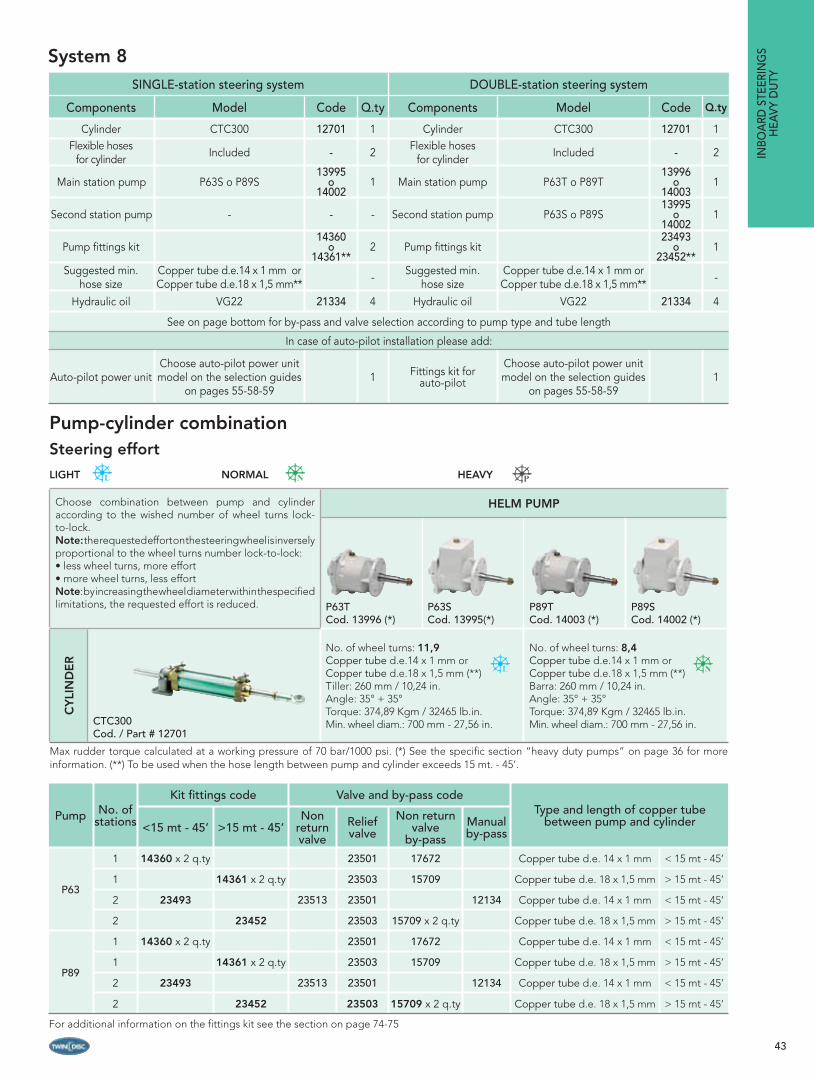
SINGLE-station steering system DOUBLE-station steering system
Components Model Code Q.ty Components Model Code Q.ty
Cylinder CTC300 12701 1 Cylinder CTC300 12701 1Flexible hoses
for cylinder Included - 2 Flexible hoses for cylinder Included - 2
Main station pump P63S o P89S13995
o 14002
1 Main station pump P63T o P89T13996
o 14003
1
Second station pump - - - Second station pump P63S o P89S13995
o 14002
1
Pump fi ttings kit14360
o 14361**
2 Pump fi ttings kit23493
o 23452**
1
Suggested min. hose size
Copper tube d.e.14 x 1 mm orCopper tube d.e.18 x 1,5 mm** - Suggested min.
hose sizeCopper tube d.e.14 x 1 mm orCopper tube d.e.18 x 1,5 mm** -
Hydraulic oil VG22 21334 4 Hydraulic oil VG22 21334 4
See on page bottom for by-pass and valve selection according to pump type and tube length
In case of auto-pilot installation please add:
Auto-pilot power unitChoose auto-pilot power unit model on the selection guides
on pages 55-58-591 Fittings kit for
auto-pilot
Choose auto-pilot power unit model on the selection guides
on pages 55-58-591
System 8
Pump No. of stations
Kit fi ttings code Valve and by-pass codeType and length of copper tube
between pump and cylinder<15 mt - 45’ >15 mt - 45’Non
return valve
Relief valve
Non return valve
by-passManual by-pass
P63
1 14360 x 2 q.ty 23501 17672 Copper tube d.e. 14 x 1 mm < 15 mt - 45’
1 14361 x 2 q.ty 23503 15709 Copper tube d.e. 18 x 1,5 mm > 15 mt - 45’
2 23493 23513 23501 12134 Copper tube d.e. 14 x 1 mm < 15 mt - 45’
2 23452 23503 15709 x 2 q.ty Copper tube d.e. 18 x 1,5 mm > 15 mt - 45’
P89
1 14360 x 2 q.ty 23501 17672 Copper tube d.e. 14 x 1 mm < 15 mt - 45’
1 14361 x 2 q.ty 23503 15709 Copper tube d.e. 18 x 1,5 mm > 15 mt - 45’
2 23493 23513 23501 12134 Copper tube d.e. 14 x 1 mm < 15 mt - 45’
2 23452 23503 15709 x 2 q.ty Copper tube d.e. 18 x 1,5 mm > 15 mt - 45’
For additional information on the fi ttings kit see the section on page 74-75
INBO
ARD
STE
ERIN
GS
HEA
VY D
UTY
Choose combination between pump and cylinder according to the wished number of wheel turns lock-to-lock.Note: the requested effort on the steering wheel is inversely proportional to the wheel turns number lock-to-lock:• less wheel turns, more effort • more wheel turns, less effort Note: by increasing the wheel diameter within the specifi ed limitations, the requested effort is reduced.
HELM PUMP
P63TCod. 13996 (*)
P63SCod. 13995(*)
P89TCod. 14003 (*)
P89SCod. 14002 (*)
CY
LIN
DE
R
CTC300Cod. / Part # 12701
No. of wheel turns: 11,9Copper tube d.e.14 x 1 mm orCopper tube d.e.18 x 1,5 mm (**)Tiller: 260 mm / 10,24 in.Angle: 35° + 35°Torque: 374,89 Kgm / 32465 lb.in.Min. wheel diam.: 700 mm - 27,56 in.
No. of wheel turns: 8,4Copper tube d.e.14 x 1 mm orCopper tube d.e.18 x 1,5 mm (**)Barra: 260 mm / 10,24 in.Angle: 35° + 35°Torque: 374,89 Kgm / 32465 lb.in.Min. wheel diam.: 700 mm - 27,56 in.
Max rudder torque calculated at a working pressure of 70 bar/1000 psi. (*) See the specifi c section “heavy duty pumps” on page 36 for more information. (**) To be used when the hose length between pump and cylinder exceeds 15 mt. - 45’.
Pump-cylinder combinationSteering effort
LIGHT NORMAL HEAVY
44
System 9
Pump No. of stations
Kit fi ttings code Valve and by-pass codeType and length of copper tube
between pump and cylinder<15 mt - 45’ >15 mt - 45’Non
return valve
Relief valve
Non return valve
by-passManual by-pass
P63
1 14360 x 2 q.ty 23501 17672 Copper tube d.e. 14 x 1 mm < 15 mt - 45’
1 14361 x 2 q.ty 23503 15709 Copper tube d.e. 18 x 1,5 mm > 15 mt - 45’
2 23493 23513 23501 12134 Copper tube d.e. 14 x 1 mm < 15 mt - 45’
2 23452 23503 15709 x 2 q.ty Copper tube d.e. 18 x 1,5 mm > 15 mt - 45’
P89
1 14360 x 2 q.ty 23501 17672 Copper tube d.e. 14 x 1 mm < 15 mt - 45’
1 14361 x 2 q.ty 23503 15709 Copper tube d.e. 18 x 1,5 mm > 15 mt - 45’
2 23493 23513 23501 12134 Copper tube d.e. 14 x 1 mm < 15 mt - 45’
2 23452 23503 15709 x 2 q.ty Copper tube d.e. 18 x 1,5 mm > 15 mt - 45’For additional information on the fi ttings kit see the section on page 74-75
SINGLE-station steering system DOUBLE-station steering systemComponents Model Code Q.ty Components Model Code Q.ty
Cylinder CTC400 o CTD31015697
o 15698
1 Cylinder CTC400 o CTD31015697
o15698
1
Flexible hoses for cylinder Included - 2 Flexible hoses for cylinder Included - 2
Main station pump P63S o P89S13995
o 14002
1 Main station pump P63T o P89T13996
o 14003
1
Second station pump - - - Second station pump P63S o P89S13995
o 14002
1
Pump fi ttings kit14360
o 14361**
2 Pump fi ttings kit23493
o 23452**
1
Suggested min. hose size
Copper tube d.e.14 x 1 mm orCopper tube d.e.18 x 1,5 mm** - Suggested min.
hose sizeCopper tube d.e.14 x 1 mm orCopper tube d.e.18 x 1,5 mm** -
Hydraulic oil VG22 21334 4 Hydraulic oil VG22 21334 4
See on page bottom for by-pass and valve selection according to pump type and tube length
In case of auto-pilot installation please add:
Auto-pilot power unitChoose auto-pilot power unit model on the selection guides
on pages 55-58-591 Fittings kit for
auto-pilot
Choose auto-pilot power unit model on the selection guides
on pages 55-58-591
INBO
ARD
STEERING
SH
EAVY DU
TY
Max rudder torque calculated at a working pressure of 70 bar/1000 psi. (*) See the specifi c section “heavy duty pumps” on page 36 for more information. (**) To be used when the hose length between pump and cylinder exceeds 15 mt. - 45’.
Choose combination between pump and cylinder according to the wished number of wheel turns lock-to-lock.Note: the requested effort on the steering wheel is inversely proportional to the wheel turns number lock-to-lock:• less wheel turns, more effort • more wheel turns, less effort Note: by increasing the wheel diameter within the specifi ed limitations, the requested effort is reduced.
HELM PUMP
P63TCod. 13996 (*)
P63SCod. 13995(*)
P89TCod. 14003 (*)
P89SCod. 14002 (*)
CY
LIN
DE
R
CTC400Cod. / Part # 15697
No. of wheel turns: 15,9Copper tube d.e.14x1 mm or copper tube d.e.18x1,5 mm (**)Tiller: 350 mm / 13,78 in.Angle: 35° + 35°Torque: 400 Kgm / 34780 lb.in.Min. wheel diam.: 700 mm - 27,56 in.
No. of wheel turns: 11,2Copper tubed.e.14x1 mm or copper tube d.e.18x1,5 mm (**)Tiller: 350 mm / 13,78 in.Angle: 35° + 35°Torque: 400 Kgm / 34780 lb.in.Min. wheel diam.: 700 mm - 27,56 in.
CTD310Cod. / Part # 15698
No. of wheel turns: 13,4Copper tube d.e.14x1 mm or copper tube d.e.18x1,5 mm (**)Tiller: 175 mm / 6,88 in.Angle: 35° + 35°Torque: 422 Kgm / 36693 lb.in.Min. wheel diam.: 700 mm - 27,56 in.
No. of wheel turns: 9,5Copper tube d.e.14x1 mm or copper tube d.e.18x1,5 mm (**)Tiller : 260 mm / 10,24 in.Angle : 35° + 35°Torque: 422 Kgm / 36693 lb.in.Min. wheel diam.: 700 mm - 27,56 in.
Pump-cylinder combinationSteering effort LIGHT NORMAL HEAVY

45
System 10
Pump No. of stations
Kit fi ttings code Valve and by-pass codeType and length of copper tube
between pump and cylinder<15 mt - 45’ >15 mt - 45’Non
return valve
Relief valve
Non return valve
by-passManual by-pass
P89
1 14360 x 2 q.ty 23501 17672 Copper tube d.e. 14 x 1 mm < 15 mt - 45’
1 14361 x 2 q.tà 23503 15709 Copper tube d.e. 18 x 1,5 mm > 15 mt - 45’
2 23493 23513 23501 12134 Copper tube d.e. 14 x 1 mm < 15 mt - 45’
2 23452 23503 15709 x 2 q.ty Copper tube d.e. 18 x 1,5 mm > 15 mt - 45’
P1051 Included 23503 15709 Copper tube d.e. 18 x 1,5 mm Any length
2 23518 23503 15709 x 2 q.ty Copper tube d.e. 18 x 1,5 mm Any length
SINGLE-station steering system DOUBLE-station steering systemComponents Model Code Q.ty Components Model Code Q.ty
Cylinder CTD450 15699 1 Cylinder CTD450 15699 1
Flexible hoses for cylinder Included - 2 Flexible hoses for cylinder Included - 2
Main station pump P89S o P10514002
o14052
1 Main station pump P89T o P10514003
o14052
1
Second station pump - - - Second station pump P89S o P10514002
o14052
1
Pump fi ttings kit14360
o 14361**
2 Pump fi ttings kit See table on page bottom 1
Suggested min. hose size
Copper tube d.e.14 x 1 mm orCopper tube d.e.18 x 1,5 mm** - Suggested min.
hose sizeCopper tube d.e.14 x 1 mm or Copper tube d.e.18 x 1,5 mm** -
Hydraulic oil VG22 21334 4 Hydraulic oil VG22 21334 4
See on page bottom for by-pass and valve selection according to pump type and tube length
In case of auto-pilot installation please add:
Auto-pilot power unitChoose auto-pilot power unit model on the selection guides
on pages 55-58-591 Fittings kit for
auto-pilot
Choose auto-pilot power unit model on the selection guides
on pages 55-58-591
INBO
ARD
STE
ERIN
GS
HEA
VY D
UTY
Choose combination between pump and cylinder according to the wished number of wheel turns lock-to-lock.Note: the requested effort on the steering wheel is inversely proportional to the wheel turns number lock-to-lock:• less wheel turns, more effort • more wheel turns, less effort Note: by increasing the wheel diameter, the requested effort is reduced.
HELM PUMP
P89TCod. 14003 (*)
P89SCod. 14002 (*)
P105Cod. 14052 (*)
CY
LIN
DE
R
CTD450Cod. / Part # 15699
No. of wheel turns: 14,2Copper tube d.e.14 x 1 mm orcopper tube d.e.18 x 1,5 mm**Tiller: 260 mm / 10,24 in.Angle: 35° + 35°Torque: 633 Kgm / 55040 lb.in.Min. wheel diam.: 700 mm-27,56 in.
No. of wheel turns: 14,2Copper tube d.e.14 x 1 mm -copper tube d.e.18 x 1,5 mm**Tiller: 260 mm / 10,24 in.Angle: 35° + 35°Torque: 633 Kgm / 55040 lb.in.Min. wheel diam.: 700 mm-27,56 in.
No. of wheel turns: 12,1Copper tube d.e.14 x 1 mm -copper tube d.e.18 x 1,5 mm**Tiller: 260 mm / 10,24 in.Angle: 35° + 35°Torque: 633 Kgm / 55040 lb.in.Min. wheel diam.: 1000 mm-39,37in.
Max rudder torque calculated at a working pressure of 70 bar/1000 psi. (*) See the specifi c section “heavy duty pumps” on page 36 for more information. (**) To be used when the hose length between pump and cylinder exceeds 15 mt. - 45’.
For additional information on the fi ttings kit see the section on page 74-75
Pump-cylinder combinationSteering effort LIGHT NORMAL HEAVY
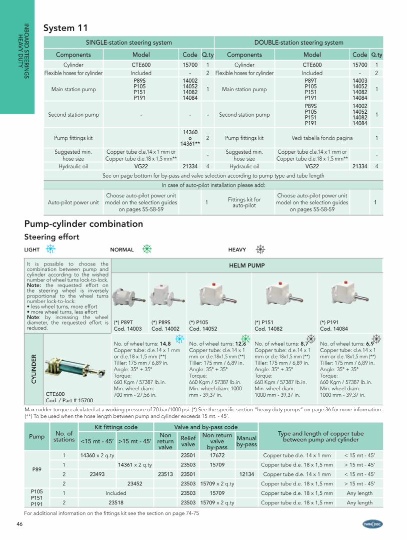
46
System 11
Pump No. of stations
Kit fi ttings code Valve and by-pass codeType and length of copper tube
between pump and cylinder<15 mt - 45’ >15 mt - 45’Non
return valve
Relief valve
Non return valve
by-passManual by-pass
P89
1 14360 x 2 q.ty 23501 17672 Copper tube d.e. 14 x 1 mm < 15 mt - 45’
1 14361 x 2 q.ty 23503 15709 Copper tube d.e. 18 x 1,5 mm > 15 mt - 45’
2 23493 23513 23501 12134 Copper tube d.e. 14 x 1 mm < 15 mt - 45’
2 23452 23503 15709 x 2 q.ty Copper tube d.e. 18 x 1,5 mm > 15 mt - 45’P105P151P191
1 Included 23503 15709 Copper tube d.e. 18 x 1,5 mm Any length
2 23518 23503 15709 x 2 q.ty Copper tube d.e. 18 x 1,5 mm Any length
SINGLE-station steering system DOUBLE-station steering system
Components Model Code Q.ty Components Model Code Q.ty
Cylinder CTE600 15700 1 Cylinder CTE600 15700 1Flexible hoses for cylinder Included - 2 Flexible hoses for cylinder Included - 2
Main station pumpP89S P105 P151 P191
14002140521408214084
1 Main station pumpP89T P105 P151 P191
14003140521408214084
1
Second station pump - - - Second station pumpP89S P105 P151 P191
14002140521408214084
1
Pump fi ttings kit14360
o 14361**
2 Pump fi ttings kit Vedi tabella fondo pagina 1
Suggested min. hose size
Copper tube d.e.14 x 1 mm orCopper tube d.e.18 x 1,5 mm**
- Suggested min. hose size
Copper tube d.e.14 x 1 mm orCopper tube d.e.18 x 1,5 mm**
-
Hydraulic oil VG22 21334 4 Hydraulic oil VG22 21334 4
See on page bottom for by-pass and valve selection according to pump type and tube length
In case of auto-pilot installation please add:
Auto-pilot power unitChoose auto-pilot power unit model on the selection guides
on pages 55-58-591 Fittings kit for
auto-pilot
Choose auto-pilot power unit model on the selection guides
on pages 55-58-591
INBO
ARD
STEERING
SH
EAVY DU
TY
Max rudder torque calculated at a working pressure of 70 bar/1000 psi. (*) See the specifi c section “heavy duty pumps” on page 36 for more information. (**) To be used when the hose length between pump and cylinder exceeds 15 mt. - 45’.
It is possible to choose the combination between pump and cylinder according to the wished number of wheel turns lock-to-lock.Note: the requested effort on the steering wheel is inversely proportional to the wheel turns number lock-to-lock:• less wheel turns, more effort • more wheel turns, less effort Note: by increasing the wheel diameter, the requested effort is reduced.
HELM PUMP
(*) P89TCod. 14003
(*) P89SCod. 14002
(*) P105Cod. 14052
(*) P151Cod. 14082
(*) P191Cod. 14084
CY
LIN
DE
R
CTE600Cod. / Part # 15700
No. of wheel turns: 14,8Copper tube: d.e.14 x 1 mmor d.e.18 x 1,5 mm (**)Tiller: 175 mm / 6,89 in.Angle: 35° + 35°Torque: 660 Kgm / 57387 lb.in.Min. wheel diam: 700 mm - 27,56 in.
No. of wheel turns: 12,6Copper tube: d.e.14 x 1 mm or d.e.18x1,5 mm (**)Tiller: 175 mm / 6,89 in.Angle: 35° + 35°Torque: 660 Kgm / 57387 lb.in.Min. wheel diam: 1000 mm - 39,37 in.
No. of wheel turns: 8,7Copper tube: d.e.14 x 1 mm or d.e.18x1,5 mm (**)Tiller: 175 mm / 6,89 in.Angle: 35° + 35°Torque: 660 Kgm / 57387 lb.in.Min. wheel diam: 1000 mm - 39,37 in.
No. of wheel turns: 6,9Copper tube: d.e.14 x 1 mm or d.e.18x1,5 mm (**)Tiller: 175 mm / 6,89 in.Angle: 35° + 35°Torque: 660 Kgm / 57387 lb.in.Min. wheel diam: 1000 mm - 39,37 in.
For additional information on the fi ttings kit see the section on page 74-75
Pump-cylinder combinationSteering effort
LIGHT NORMAL HEAVY
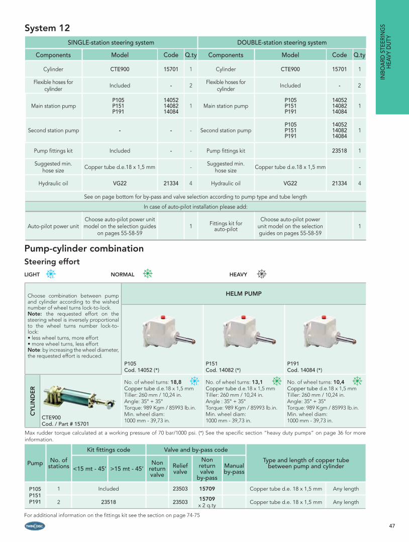
47
System 12
Choose combination between pump and cylinder according to the wished number of wheel turns lock-to-lock.Note: the requested effort on the steering wheel is inversely proportional to the wheel turns number lock-to-lock:• less wheel turns, more effort • more wheel turns, less effort Note: by increasing the wheel diameter, the requested effort is reduced.
HELM PUMP
P105Cod. 14052 (*)
P151Cod. 14082 (*)
P191Cod. 14084 (*)
CY
LIN
DE
R
CTE900Cod. / Part # 15701
No. of wheel turns: 18,8Copper tube d.e.18 x 1,5 mmTiller: 260 mm / 10,24 in.Angle: 35° + 35°Torque: 989 Kgm / 85993 lb.in.Min. wheel diam: 1000 mm - 39,73 in.
No. of wheel turns: 13,1Copper tube d.e.18 x 1,5 mmTiller: 260 mm / 10,24 in.Angle : 35° + 35°Torque: 989 Kgm / 85993 lb.in.Min. wheel diam: 1000 mm - 39,73 in.
No. of wheel turns: 10,4Copper tube d.e.18 x 1,5 mmTiller: 260 mm / 10,24 in.Angle: 35° + 35°Torque: 989 Kgm / 85993 lb.in.Min. wheel diam: 1000 mm - 39,73 in.
Pump No. of stations
Kit fi ttings code Valve and by-pass code
Type and length of copper tube between pump and cylinder<15 mt - 45’ >15 mt - 45’
Non return valve
Relief valve
Non return valve
by-pass
Manual by-pass
P105P151P191
1 Included 23503 15709 Copper tube d.e. 18 x 1,5 mm Any length
2 23518 23503 15709 x 2 q.ty Copper tube d.e. 18 x 1,5 mm Any length
SINGLE-station steering system DOUBLE-station steering system
Components Model Code Q.ty Components Model Code Q.ty
Cylinder CTE900 15701 1 Cylinder CTE900 15701 1
Flexible hoses for cylinder Included - 2
Flexible hoses for cylinder Included - 2
Main station pumpP105 P151 P191
140521408214084
1 Main station pumpP105 P151 P191
140521408214084
1
Second station pump - - - Second station pumpP105 P151 P191
140521408214084
1
Pump fi ttings kit Included - - Pump fi ttings kit 23518 1
Suggested min. hose size Copper tube d.e.18 x 1,5 mm -
Suggested min. hose size Copper tube d.e.18 x 1,5 mm -
Hydraulic oil VG22 21334 4 Hydraulic oil VG22 21334 4
See on page bottom for by-pass and valve selection according to pump type and tube length
In case of auto-pilot installation please add:
Auto-pilot power unitChoose auto-pilot power unit model on the selection guides
on pages 55-58-591 Fittings kit for
auto-pilot
Choose auto-pilot power unit model on the selection guides on pages 55-58-59
1
INBO
ARD
STE
ERIN
GS
HEA
VY D
UTY
Max rudder torque calculated at a working pressure of 70 bar/1000 psi. (*) See the specifi c section “heavy duty pumps” on page 36 for more information.
For additional information on the fi ttings kit see the section on page 74-75
Pump-cylinder combinationSteering effort
LIGHT NORMAL HEAVY

48
System 13
Pump No. of stations
Kit fi ttings code Valve and by-pass code
Type and length of copper tube between pump and cylinder
<15 mt - 45’ >15 mt - 45’Non
return valve
Relief valve
Non return valve
by-pass
Manual by-pass
P151P191
1 Included 23503 15709 Copper tube d.e. 18 x 1,5 mm Any length
2 23518 23503 15709 x 2 q.ty Copper tube d.e. 18 x 1,5 mm Any length
SINGLE-station steering system DOUBLE-station steering system
Components Model Code Q.ty Components Model Code Q.ty
Cylinder CTE1200 15702 1 Cylinder CTE1200 15702 1
Flexible hoses for cylinder Included - 2 Flexible hoses
for cylinder Included - 2
Main station pump P151 P191
1408214084 1 Main station pump P151
P191 1408214084 1
Second station pump - - - Second station pump P151 P191
1408214084 1
Pump fi ttings kit Included - - Pump fi ttings kit 23518 1
Suggested min. hose size Copper tube d.e.18 x 1,5 mm - Suggested min.
hose size Copper tube d.e.18 x 1,5 mm -
Hydraulic oil VG22 21334 4 Hydraulic oil VG22 21334 4
See on page bottom for by-pass and valve selection according to pump type and tube length
In case of auto-pilot installation please add:
Auto-pilot power unitChoose auto-pilot power unit model on the selection guides
on pages 55-58-591 Fittings kit for
auto-pilot
Choose auto-pilot power unit model on the selection guides on pages 55-58-59
1
Choose combination between pump and cylinder according to the wished number of wheel turns lock-to-lock.Note: the requested effort on the steering wheel is inversely proportional to the wheel turns number lock-to-lock:• less wheel turns, more effort • more wheel turns, less effort Note: by increasing the wheel diameter within the specifi ed limitations, the requested effort is reduced.
HELM PUMP
P151Cod. 14082 (*)
P191Cod. 14084 (*)
CY
LIN
DE
R
CTE1200Cod. / Part # 15702
No. of wheel turns: 17,5Copper tube d.e.18 x 1,5 mm Tiller: 350 mm / 13,78 in.Angle: 35° + 35°Torque: 1318 Kgm / 114601 lb.in.Min. wheel diam.: 1000 mm - 39,37 in.
No. of wheel turns: 13,8Copper tube d.e.18 x 1,5 mmTiller: 350 mm / 13,78 in.Angle: 35° + 35°Torque: 1318 Kgm / 114601 lb.in.Min. wheel diam.: 1000 mm - 39,37 in.
INBO
ARD
STEERING
SH
EAVY DU
TY
Max rudder torque calculated at a working pressure of 70 bar/1000 psi. (*) See the specifi c section “heavy duty pumps” on page 36 for more information.
For additional information on the fi ttings kit see the section on page 74-75
Pump-cylinder combinationSteering effort
LIGHT NORMAL HEAVY

49
System 14
Choose combination between pump and cylinder according to the wished number of wheel turns lock-to-lock.Note: the requested effort on the steering wheel is inversely proportional to the wheel turns number lock-to-lock:• less wheel turns, more effort • more wheel turns, less effort Note: by increasing the wheel diameter within the specifi ed limitations, the requested effort is reduced.
HELM PUMP
P191 Cod. 14084 (*)
CY
LIN
DE
R
CTF1600Cod. / Part # 15703
No. of wheel turns: 20,2Copper tube d.e.18 x 1,5 mm Tiller: 350 mm / 13,78 in.Angle: 35° + 35°Torque: 1928 Kgm / 167640 lb.in.Min. wheel diam.: 1000 mm - 39,37 in.
Pump No. of stations
Kit fi ttings code Valve and by-pass codeType and length of copper tube
between pump and cylinder<15 mt - 45’ >15 mt - 45’
Non return valve
Relief valve
Non return valve
by-passManual by-pass
P1911 Included 23503 15709 Copper tube d.e. 18 x 1,5 mm Any length
2 23518 23503 15709 x 2 q.ty Copper tube d.e. 18 x 1,5 mm Any length
SINGLE-station steering system DOUBLE-station steering system
Components Model Code Q.ty Components Model Code Q.ty
Cylinder CTF1600 15703 1 Cylinder CTF1600 15703 1
Flexible hoses for cylinder Included - 2 Flexible hoses f
or cylinder Included - 2
Main station pump P191 14084 1 Main station pump P191 14084 1
Second station pump - - - Second station pump P191 14084 1
Pump fi ttings kit Included - - Pump fi ttings kit 23518 1
Suggested min. hose size Copper tube d.e.18 x 1,5 mm - Suggested min.
hose size Copper tube d.e.18 x 1,5 mm -
Hydraulic oil VG22 21334 4 Hydraulic oil VG22 21334 4
See on page bottom for by-pass and valve selection according to pump type and tube length
In case of auto-pilot installation please add:
Auto-pilot power unitChoose auto-pilot power unit model on the selection guides
on pages 55-58-591 Fittings kit for
auto-pilot
Choose auto-pilot power unit model on the selection guides on pages 55-58-59
1
INBO
ARD
STE
ERIN
GS
HEA
VY D
UTY
Max rudder torque calculated at a working pressure of 70 bar/1000 psi. (*) See the specifi c section “heavy duty pumps” on page 36 for more information.
For additional information on the fi ttings kit see the section on page 74-75
Pump-cylinder combinationSteering effort
LIGHT NORMAL HEAVY

50
INBO
ARD
CYLIN
DERS
HEAVY D
UTY
B C
H
FG
E
35°35°
R
D
P M
S
A
Q
NL
Technical specifi cations
Model Code Stroke Torque Thrust at 70 bar - 1000 psi Volume Tiller Angle Fittings Weight
CTC200 12695200 mm 249.93 Kgm 1750 Kgf 500 cc 175 mm
35°+35° G1/2” - d.12mm13,2 Kg
7.87 in. 21643 lb.in. 3857 lbf 30.5 cu.in 6.9 in. 29,10 lb
CTC230 12698228 mm 284.92 Kgm 1750 Kgf 570 cc 200 mm
35°+35° G1/2” - d.12mm15,3 Kg
9 in. 24674 lb.in. 3857 lbf 34.78 cu.in 7.8 in. 33,73 lb
CTC300 12701300 mm 374.89 Kgm 1750 Kgf 750 cc 260 mm
35°+35° G1/2” - d.12mm17,7 Kg
11.81 in. 32465 lb.in. 3857 lbf 45.77 cu.in 10.2 in. 39,02 lb
CTC400 15697400 mm 499.85 Kgm 1750 Kgf 1000 cc 350 mm
35°+35° G1/2” - d.12mm20,0 Kg
15.75 in. 43287 lb.in. 3857 lbf 61.02 cu.in 13.7 in. 44,1 lb
Note: the inboard cylinders mod CTC are not suitable for installations on racing boats. They are provided with fl exible hoses type SAE100 R1.
Dimensions
Model Stroke A B C D E F G H L M N P Q R S
CTC200200 mm 733 mm 607 mm 127 mm 28 mm 25 mm 55 mm 133 mm 385 mm 100 mm 140 mm 72 mm 112 mm 11 mm 175 mm 143 mm
7.87in. 28.86 in. 23.9 in. 5.0 in. 1.10 in. 0.98 in. 2.17 in. 5,25 in. 16.16 in. 3.94 in. 5.51 in. 2.83 in. 4.41 in. 0.43 in. 6.89 in. 5.6 in.
CTC230228 mm 789 mm 649 mm141 mm 28 mm 25 mm 55 mm 133 mm 413 mm 100 mm 140 mm 72 mm 112 mm 11 mm 200 mm 164 mm
9.0 in. 31.0 in. 25.55 in. 5.55 in. 1.10 in. 0.98 in. 2.17 in. 5,25 in. 16.26 in. 3.94 in. 5.51 in. 2.83 in. 4.41 in. 0.43 in. 7.87 in. 6.5 in.
CTC300300 mm 933 mm 757 mm177 mm 28 mm 25 mm 55 mm 133 mm 485 mm 100 mm 140 mm 72 mm 112 mm 11 mm 260 mm 215 mm
11.81 in. 36.73 in. 29.8 in. 6.97 in. 1.10 in. 0.98 in. 2.17 in. 5,25 in. 19.09 in. 3.94 in. 5.51 in. 2.83 in. 4.41 in. 0.43 in. 10.24 in. 8.5 in.
CTC400400 mm 1133 mm 907 mm 227 mm 28 mm 25 mm 55 mm 133 mm 585 mm 100 mm 140 mm 72 mm 112 mm 11 mm 350 mm 286 mm
15.75 in. 44.61 in. 35.71 in. 8.94 in. 1.10 in. 0.98 in. 2.17 in. 5,25 in. 23.0 in. 3.94 in. 5.51 in. 2.83 in. 4.41 in. 0.43 in. 13.78 in. 11.3 in.
Heavy duty inboard steering cylinders Series CTC
Technical specifi cations
Main features
Cilinder in stainless steel and brass paintedPiston rod in stainless steel for a high corrosion resistanceStainless steel cylinder baseAdjustable base either horizontally or verticallyAvailable in a range of volumes between 500 and 1000 cc Supplied with bleeders Meet ABYC standards
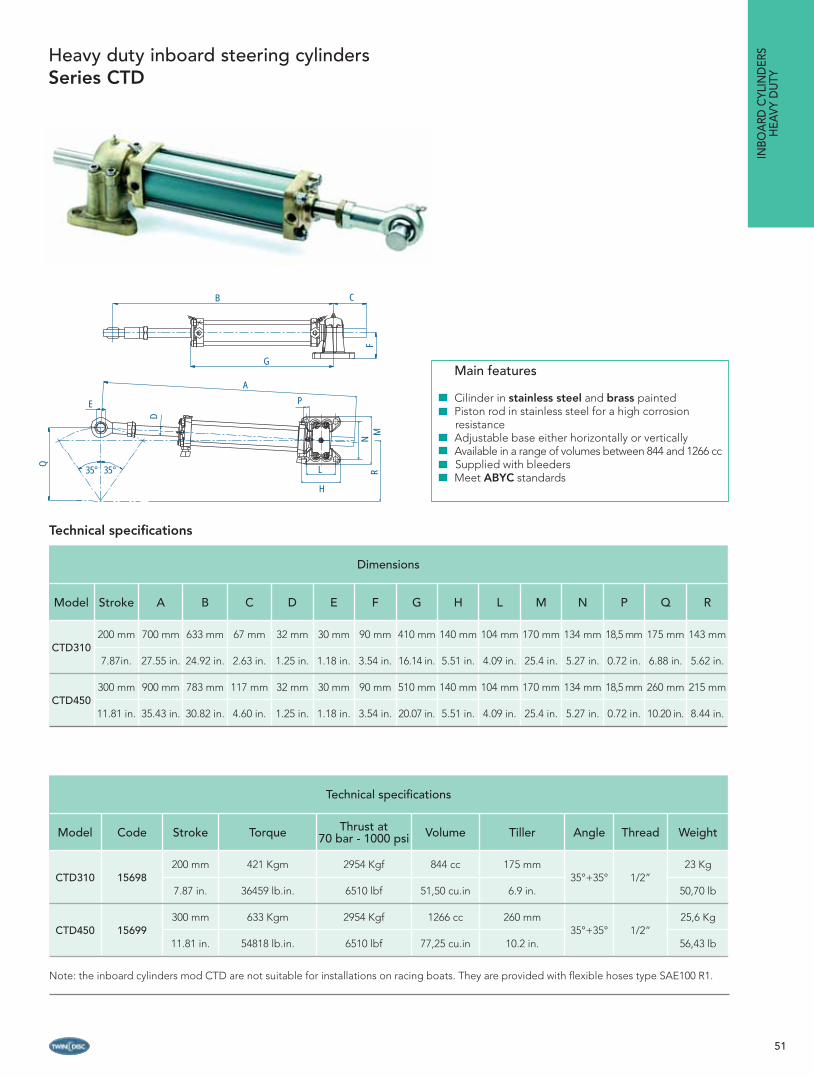
51
C
GF
B
A
E
35°35°
Q
D
P
L
H
NM
R
Technical specifi cations
Model Code Stroke Torque Thrust at 70 bar - 1000 psi Volume Tiller Angle Thread Weight
CTD310 15698200 mm 421 Kgm 2954 Kgf 844 cc 175 mm
35°+35° 1/2”23 Kg
7.87 in. 36459 lb.in. 6510 lbf 51,50 cu.in 6.9 in. 50,70 lb
CTD450 15699300 mm 633 Kgm 2954 Kgf 1266 cc 260 mm
35°+35° 1/2”25,6 Kg
11.81 in. 54818 lb.in. 6510 lbf 77,25 cu.in 10.2 in. 56,43 lb
Note: the inboard cylinders mod CTD are not suitable for installations on racing boats. They are provided with fl exible hoses type SAE100 R1.
Dimensions
Model Stroke A B C D E F G H L M N P Q R
CTD310200 mm 700 mm 633 mm 67 mm 32 mm 30 mm 90 mm 410 mm 140 mm 104 mm 170 mm 134 mm 18,5 mm 175 mm 143 mm
7.87in. 27.55 in. 24.92 in. 2.63 in. 1.25 in. 1.18 in. 3.54 in. 16.14 in. 5.51 in. 4.09 in. 25.4 in. 5.27 in. 0.72 in. 6.88 in. 5.62 in.
CTD450300 mm 900 mm 783 mm 117 mm 32 mm 30 mm 90 mm 510 mm 140 mm 104 mm 170 mm 134 mm 18,5 mm 260 mm 215 mm
11.81 in. 35.43 in. 30.82 in. 4.60 in. 1.25 in. 1.18 in. 3.54 in. 20.07 in. 5.51 in. 4.09 in. 25.4 in. 5.27 in. 0.72 in. 10.20 in. 8.44 in.
Heavy duty inboard steering cylinders Series CTD
Technical specifi cations
INBO
ARD
CYL
IND
ERS
HEA
VY D
UTY
Main features
Cilinder in stainless steel and brass paintedPiston rod in stainless steel for a high corrosion resistanceAdjustable base either horizontally or verticallyAvailable in a range of volumes between 844 and 1266 cc Supplied with bleeders Meet ABYC standards
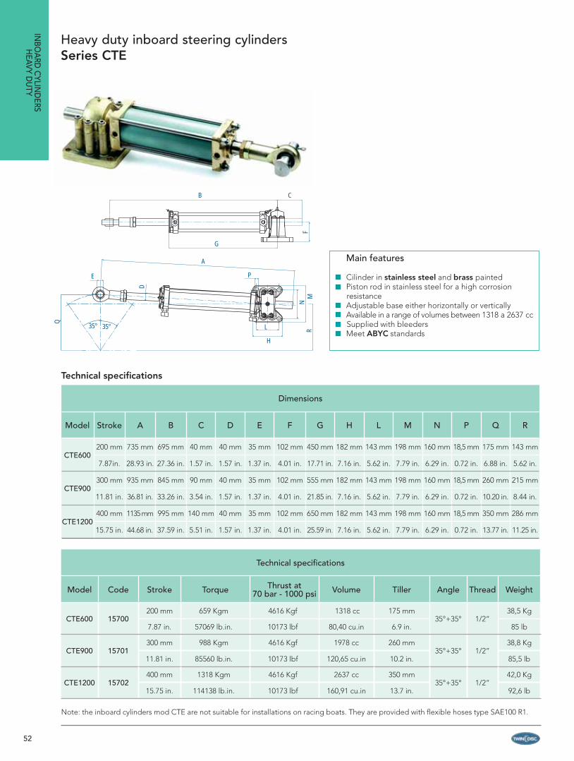
52
INBO
ARD
CYLIN
DERS
HEAVY D
UTY
F
CB
G
E
35°35°
Q
D
P
L
H
NM
R
A
Technical specifi cations
Model Code Stroke Torque Thrust at 70 bar - 1000 psi Volume Tiller Angle Thread Weight
CTE600 15700200 mm 659 Kgm 4616 Kgf 1318 cc 175 mm
35°+35° 1/2”38,5 Kg
7.87 in. 57069 lb.in. 10173 lbf 80,40 cu.in 6.9 in. 85 lb
CTE900 15701300 mm 988 Kgm 4616 Kgf 1978 cc 260 mm
35°+35° 1/2”38,8 Kg
11.81 in. 85560 lb.in. 10173 lbf 120,65 cu.in 10.2 in. 85,5 lb
CTE1200 15702400 mm 1318 Kgm 4616 Kgf 2637 cc 350 mm
35°+35° 1/2”42,0 Kg
15.75 in. 114138 lb.in. 10173 lbf 160,91 cu.in 13.7 in. 92,6 lb
Note: the inboard cylinders mod CTE are not suitable for installations on racing boats. They are provided with fl exible hoses type SAE100 R1.
Dimensions
Model Stroke A B C D E F G H L M N P Q R
CTE600200 mm 735 mm 695 mm 40 mm 40 mm 35 mm 102 mm 450 mm 182 mm 143 mm 198 mm 160 mm 18,5 mm 175 mm 143 mm
7.87in. 28.93 in. 27.36 in. 1.57 in. 1.57 in. 1.37 in. 4.01 in. 17.71 in. 7.16 in. 5.62 in. 7.79 in. 6.29 in. 0.72 in. 6.88 in. 5.62 in.
CTE900300 mm 935 mm 845 mm 90 mm 40 mm 35 mm 102 mm 555 mm 182 mm 143 mm 198 mm 160 mm 18,5 mm 260 mm 215 mm
11.81 in. 36.81 in. 33.26 in. 3.54 in. 1.57 in. 1.37 in. 4.01 in. 21.85 in. 7.16 in. 5.62 in. 7.79 in. 6.29 in. 0.72 in. 10.20 in. 8.44 in.
CTE1200400 mm 1135 mm 995 mm 140 mm 40 mm 35 mm 102 mm 650 mm 182 mm 143 mm 198 mm 160 mm 18,5 mm 350 mm 286 mm
15.75 in. 44.68 in. 37.59 in. 5.51 in. 1.57 in. 1.37 in. 4.01 in. 25.59 in. 7.16 in. 5.62 in. 7.79 in. 6.29 in. 0.72 in. 13.77 in. 11.25 in.
Technical specifi cations
Heavy duty inboard steering cylinders Series CTE
Main features
Cilinder in stainless steel and brass paintedPiston rod in stainless steel for a high corrosion resistanceAdjustable base either horizontally or verticallyAvailable in a range of volumes between 1318 a 2637 cc Supplied with bleeders Meet ABYC standards

53
B
G
C
F
E
35°35°
Q
D
AP
L H
NM
R
Technical specifi cations
Model Code Stroke Torque Thrust at 70 bar - 1000 psi Volume Tiller Angle Thread Weight
CTF1600 15703400 mm 1928 Kgm 6750 Kgf 3857 cc 350 mm
35°+35° 1/2”78,8 Kg
15.75 in. 166964 lb.in. 14850 lbf 235,27 cu.in 13,77 in. 173,72 lb
Note: the inboard cylinders mod CTF are not suitable for installations on racing boats. They are provided with fl exible hoses type SAE100 R1.
Dimensions
Model Stroke A B C D E F G H L M N P Q R
CTF1600400 mm 1205 mm 935 mm 270 mm 46 mm 36 mm 130 mm 580 mm 240 mm 190 mm 300 mm 250 mm 20,5 mm 350 mm 286 mm
15.75 in. 47.44 in. 36.81 in. 10.62 in. 1.81 in. 1.41 in. 5.11 in. 22.83 in. 9.44 in. 7.48 in. 11.81 in. 9.84 in. 0.80 in. 13.77 in. 11.25 in.
Heavy duty inboard steering cylinders Series CTF
Technical specifi cations
INBO
ARD
CYL
IND
ERS
HEA
VY D
UTY
Main features
Cilinder in stainless steel and brass paintedPiston rod in stainless steel for a high corrosion resistanceAdjustable base either horizontally or verticallyAvailable in a range of volumes from 3857 cc Supplied with bleeders Meet ABYC standards

54
AUTO-PILOT POWER UNITS
AU
TO-PILO
T POW
ER UN
ITS
The automatic pilot and other electronic navigation systems are more popular, even on small vessels: it is necessary for the equipment to be able to exchange information and work together to guarantee safe navigation.
Twin Disc has developed a complete range of auto-pilot power units that represent the best interface for your auto-pilot.
The auto-pilot power unit range can give very simple solutions in terms of working principle and installation, but extremely reliable, accurate performance.
It is possible to choose among several types of units:
- Solenoid-valve power units- Solenoid-valve power units with automatic filling- Reversible power units
Please check the different tables for the products characteristics and technical details.In order to choose the most suitable unit it is necessary to have the steering cylinder volume, from which the actuation time is calculated and the suitable model selected.
Main features
Interface with any auto-pilot Reduced dimensionsModels for any kind of applicationHigh quality materials and components for the best reliability and performanceSteering automatic fi lling device available on certain models for an easier and faster bleedingReversible and solenoid-valve power units

55
The latest version of the auto-pilot power unit with solenoid valves has a safe and accurate interface for the automatic pilot. It is equipped with a special device that allows the automatic fi lling of the steering system. This additional device allows oil to go automatically through steering hoses and any remaining air goes out the designed bleeders.By turning occasionally the steering wheel from port to starboard and vice-versa; the bleeding procedure becomes quick and easy.For any other technical specifi cations please refer to previous section under “Solenoid-valve power units”.
Auto-pilot solenoid-valve power units with automatic filling deviceMod. C03RA - C04RA
AU
TO-P
ILO
T PO
WER
UN
ITS
Order guide and technical specifi cations
Model Code Typical cylinder application
Cylinder application
Application time in
sec.Displacement Setting
pressure
Max power cons.
Therm protection
Motor nominal power
Tank capacity Weight*
CO3RAU 12V CO3RA 12V
CO3RAU 24VCO3RA 24V
23338 18044
1255212551
130 - 360 ccCTA65UCTA65
CTA75UCTA75
CTA80UCTA80
CTB110UCTB110
12,2
13,8
15,8
20,7
816 cc/min. 50 bar 11 A 16 A
125 W
7 lt 10 Kg - 20,04 lb
7,93 - 21,96 cu.in. 49,77 cu.in. 725 psi 6 A 10 A 427 in.cu 10,5 Kg - 23,14 lb
CO4RAU 12V
CO4RAU 24VCO4RA 24V
23339
1256912568
360 - 500 ccCTB130UCTB130
CTB145UCTB145CTC200CTC300
10
11,2
15,423,2
1940 cc/min.
50 bar 26 A 32 A
150 W
12 lt 15 Kg - 33,06 lb
21,96 - 30,5 cu.in. 118,34 cu.in 725 psi 13 A 16 A 732 in.cu 15,5 Kg - 34,16 lb
Dimensions
Modello A B C
CO3RAUCO3RA
370 mm 230 mm 240 mm
14,56 in. 9 in. 9,44 in.
CO4RAUCO4RA
370 mm 230 mm 380 mm
14,56 in. 9 in. 14,96 in.
Technical specifi cations and applications
Main features
Available in two models for application with steering cylinders having a volume up to 500 ccSafe and precise interface with any automatic pilotCompact design and reduced dimensionsSolenoid-valves electro-magnetically actuatedSpecial device for the steering automatic fi llingEasy and fast steering bleeding
Metrical fittings Imperial fittings
(*) Weight is intended without oil.
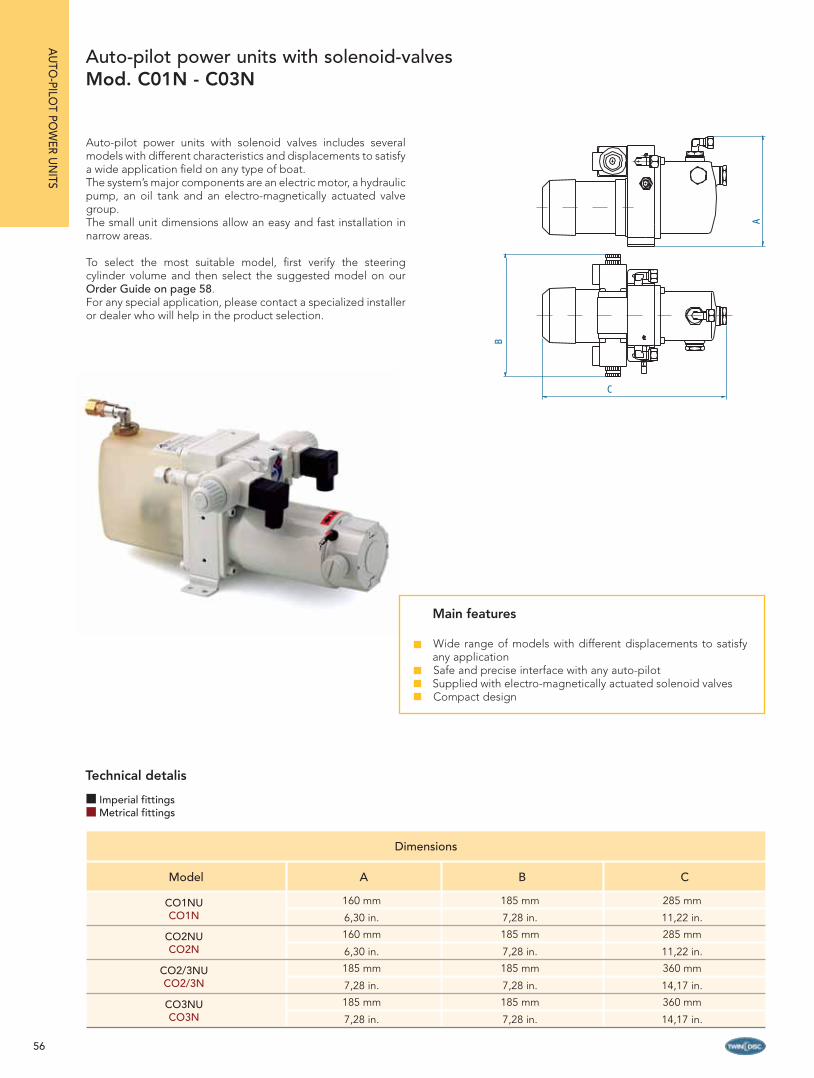
56
Dimensions
Model A B C
CO1NUCO1N
160 mm 185 mm 285 mm
6,30 in. 7,28 in. 11,22 in.
CO2NUCO2N
160 mm 185 mm 285 mm
6,30 in. 7,28 in. 11,22 in.
CO2/3NUCO2/3N
185 mm 185 mm 360 mm
7,28 in. 7,28 in. 14,17 in.
CO3NUCO3N
185 mm 185 mm 360 mm
7,28 in. 7,28 in. 14,17 in.
Auto-pilot power units with solenoid valves includes several models with different characteristics and displacements to satisfy a wide application fi eld on any type of boat.The system’s major components are an electric motor, a hydraulic pump, an oil tank and an electro-magnetically actuated valve group.The small unit dimensions allow an easy and fast installation in narrow areas.
To select the most suitable model, fi rst verify the steering cylinder volume and then select the suggested model on our Order Guide on page 58.For any special application, please contact a specialized installer or dealer who will help in the product selection.
Auto-pilot power units with solenoid-valvesMod. C01N - C03N
A
B
C
AU
TO-PILO
T POW
ER UN
ITS
Main features
Wide range of models with different displacements to satisfy any applicationSafe and precise interface with any auto-pilotSupplied with electro-magnetically actuated solenoid valvesCompact design
Technical detalis
Imperial fittingsMetrical fittings
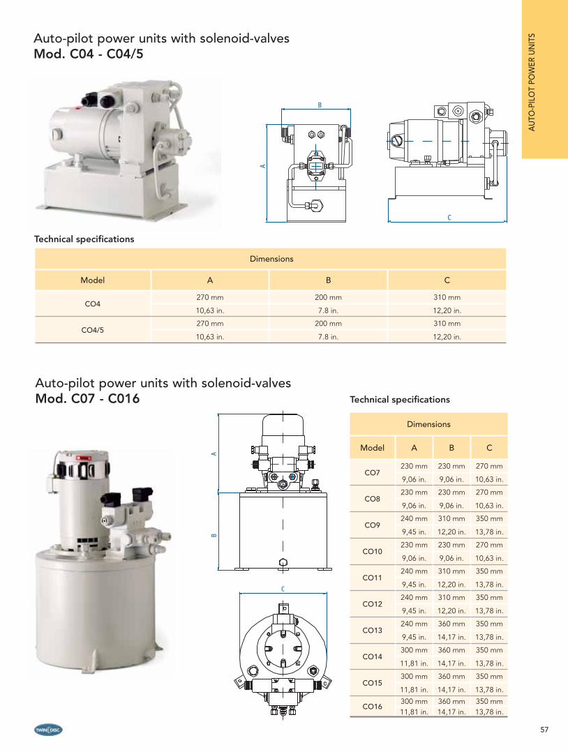
57
Dimensions
Model A B C
CO7230 mm 230 mm 270 mm
9,06 in. 9,06 in. 10,63 in.
CO8230 mm 230 mm 270 mm
9,06 in. 9,06 in. 10,63 in.
CO9240 mm 310 mm 350 mm
9,45 in. 12,20 in. 13,78 in.
CO10230 mm 230 mm 270 mm
9,06 in. 9,06 in. 10,63 in.
CO11240 mm 310 mm 350 mm
9,45 in. 12,20 in. 13,78 in.
CO12240 mm 310 mm 350 mm
9,45 in. 12,20 in. 13,78 in.
CO13240 mm 360 mm 350 mm
9,45 in. 14,17 in. 13,78 in.
CO14300 mm 360 mm 350 mm
11,81 in. 14,17 in. 13,78 in.
CO15300 mm 360 mm 350 mm
11,81 in. 14,17 in. 13,78 in.
CO16300 mm 360 mm 350 mm11,81 in. 14,17 in. 13,78 in.
Auto-pilot power units with solenoid-valvesMod. C04 - C04/5
Dimensions
Model A B C
CO4270 mm 200 mm 310 mm
10,63 in. 7.8 in. 12,20 in.
CO4/5270 mm 200 mm 310 mm
10,63 in. 7.8 in. 12,20 in.
Technical specifi cations
Auto-pilot power units with solenoid-valvesMod. C07 - C016
C
A
B
C
AB
Technical specifi cations
AU
TO-P
ILO
T PO
WER
UN
ITS

58
Order Guide and technical specifi cations
Model Code Typical cylinder application
Cylinderapplication
Application time
in sec.Displacement Setting
pressure
Max power cons.
Therm protection
Motor nominal power
Tank capacity Weight*
CO1NU 12VCO1N 12V
CO1NU 24VCO1N 24V
21313 12517
2131412518
70 - 100 cc
-
depending on the
cylinder volume
360 cc/min 50 bar 7 A 10 A
60 W
0,55 lt 6.5 Kg
4.27 - 6.1 cu.in 21.97 cu.in/min 725 psi 4.5 A 10 A33,56in.cu
14.33 lb
CO2NU 12VCO2N 12V
CO2NU 24VCO2N 24V
2131512532
2131612533
115 - 130 ccCTA40UCTA40 14,5
480 cc/min 50 bar 9.4 A 10 A
60 W
0,55 lt 6.5 Kg
6.1 - 7.93 cu.in 29.30 cu.in/min 725 psi 6 A 10 A33,56in.cu
14.33 lb
CO2/3NU 12VCO2/3N 12V
CO2/3NU 24VCO2/3N 24V
21317 12521
2131812522
130 - 220 cc CTA65UCTA65
CTA75U CTA75
CTA80U CTA80
14
15,6
17,9
720 cc/min 50 bar 16 A 20 A
100 W
0,95 lt 8.5 Kg
7.93 - 13.42 cu.in 43.95 cu.in/min 725 psi 10 A 16 A57,97in.cu
18.73 lb
CO3NU 12VCO3N 12V
CO3NU 24VCO3N 24V
2131915314
2132012549
220 - 360 cc CTB110U CTB110
CTB130UCTB130
CTB145UCTB145
13,8
15,8
17,7
1220 cc/min 50 bar 18 A 20 A
100 W
0,95 lt 8.5 Kg
13.42 - 21.96 cu.in 74.48 cu.in/min 725 psi 12 A 16 A57,97in.cu
18.73 lb
CO4 12V CO4 24V
1255911342
360 - 500 cc CTC200 CTC230
1618
1860 cc/min 45 bar 18 A 20 A150 W
3,0 lt 14 Kg
21.96 - 30.5 cu.in113.55 cu.in/
min652 psi 10 A 16 A 183 in.cu 30.86 lb
CO4/5 12V CO4/5 24V
1255512556
500 - 570 cc CTC200CTC230 CTC300
12,314
18,4
2440 cc/min 45 bar 20 A 25 A150 W
3,0 lt 14 Kg
30.50 - 34.77 cu.in148.96
cu.in/min652 psi 12 A 16 A 183 in.cu 30.86 lb
CO7 24V 12581500 - 570 cc
CTC300 212100 cc/min 55 bar - -
300 W12,0 lt 25 Kg
30.50 - 34.77 cu.in128.20
cu.in/min797 psi 18 A 20 A 732 in.cu 55.11 lb
CO8 24V 12582570 - 750 cc
CTC300 15,72850 cc/min 55 bar - -
300 W12,0 lt 25 Kg
34.77 - 45.75 cu.in173.99
cu.in/min797 psi 21 A 25 A 732 in.cu 55.11 lb
CO9 24V 12584750 - 1000 cc CTC400
CTD31016,614
3600 cc/min 55 bar - -550 W
25,0 lt 40 Kg
45.75 - 61.00 cu.in219.78
cu.in/min797 psi 21 A 25 A
1525in.cu
88.18 lb
CO10 24V 124971000 - 1200 cc CTC400
CTD31013
10,9
4650 cc/min 55 bar - -300 W
12,0 lt 40 Kg
61.00 - 73.3 cu.in283.88
cu.in/min797 psi 30 A 32 A 732 in.cu 88.18 lb
CO11 24V 124991200 - 1250 cc
CTD450 16,34650 cc/min 55 bar - -
550 W25,0 lt 40 Kg
73,28 - 76,27 cu.in283.88
cu.in/min797 psi 35 A 40 A
1525in.cu
88.18 lb
CO12 24V 125001250 - 1350 cc
CTE600 14,65400 cc/min 55 bar - -
550 W25,0 lt 40 Kg
76,27 - 82,38 cu.in. 329.4 cu.in/min 797 psi 35 A 40 A1525in.cu
88,18 lb
CO13 24V 125021350 - 1750 cc
CTE600 117200 cc/min 55 bar - -
550 W32,0 lt 43 Kg
82,38 - 106,79 cu.in.
439.2 cu.in/min 797 psi 40 A 50 A1952in.cu
94,80 lb
CO14 24V 125031250 - 1350 cc
CTE600 12,56300 cc/min 55 bar - -
1100 W32,0 lt 43 Kg
76,27 - 84,38 cu.in. 384.3 cu.in/min 797 psi 55 A 63 A1952in.cu
94,80 lb
CO15 24V 125041750 - 2000 cc
CTE900 139150 cc/min 55 bar - -
1100 W32,0 lt 43 Kg
106,79 - 122 cu.in.558.15
cu.in/min797 psi 55 A 63 A
1952in.cu
94,80 lb
CO16 24V 125072000 - 3900 cc CTE1200
CTF160013,319,5
11850 cc/min 55 bar - -1100 W
32,0 lt 43 Kg
122 - 238 cu.in722.85
cu.in/min797 psi 65 A 80 A
1952in.cu
94,80 lb
Technical specifi cations and applications of solenoid-valve auto-pilot power units
AU
TO-PILO
T POW
ER UN
ITS
(*) Weight is intended without oil.
Metrical fittings Imperial fittings

59
A
B
C
Dimensions
Model A B C
CO1RU - CO1R 160 mm - 6,30 in. 155 mm - 6,10 in. 285 mm - 11,22 in.
CO2RU - CO2R 160 mm - 6,30 in. 155 mm - 6,10 in. 285 mm - 11,22 in.
CO3RU - CO3R 185 mm - 7,28 in. 155 mm - 6,10 in. 360 mm - 14,17 in.
CO4NRU - CO4NR 185 mm - 7,28 in. 155 mm - 6,10 in. 360 mm - 14,17 in.
Order Guide and technical specifi cations
Model Code Typical cylinder application
Cylinderapplication
Application time
in sec.Displacement Setting
pressure
Max power cons.
Therm protection
Motor nominal power
Tank capacity Weight*
CO1RU 12VCO1R 12V
CO1RU 24VCO1R 24V
2130512519
2130611341
70 - 100 cc
-
depending on the
cylinder volume
360 cc/min 50 bar 7 A 10 A
80 W
0.55 lt 6.5 Kg
4.27 - 6.1 cu.in 21.97 cu.in 725 psi 4.5 A 10 A 33,56 in.cu 14,33 lb
CO2RU 12V CO2R 12V
CO2RU 24VCO2R 24V
21307 12535
2130812536
115 - 130 cc
CTA40U - CTA40 14,5
480 cc/min 50 bar 8,5 A 10 A
80 W
0.55 lt 6.5 Kg
6.1 - 7.93 cu.in 29.30 cu.in 725 psi 4,5 A 10 A 33,56 in.cu 14,33 lb
CO3RU 12VCO3R 12V
CO3RU 24VCO3R 24V
2130915710
2131012550
130 - 360 ccCTA40U - CTA40CTA75U - CTA75CTA80U - CTA80
CTB110U - CTB110 CTB130U - CTB130CTB145U - CTB145
10,511,713,417,620,1822,5
960 cc/min 50 bar 10 A 16 A
125 W
0.95 lt 8.5 Kg
7.93 - 13.42 cu.in 58.56 cu.in 725 psi 7 A 10 A 33,56 in.cu 18,73 lb
CO4NRU 12VCO4NR 12V
CO4NRU 24VCO4NR 24V
2131115711
2131215712
360 - 500 cc
CTC200CT230
15,617,8
1920 cc/min 50 bar 22 A 25 A
150 W
0.95 lt 8.5 Kg
21.96 - 30,5 cu.in 117.12 cu.in 725 psi 11 A 16 A 33,56 in.cu 18,73 lb
Four different models of reversible power units are available for auto-pilot application with steering cylinders with a volume up to 500 cc. They should be used for all applications where the power consumption is critical and needs to be as low as possible. They have the same performances as the solenoid-valve units, ensuring an accurate and reliable interface with the auto-pilot software.
The small dimensions allow installation in very narrow places.The unit comprised of a reversible electric motor, a reversible hydraulic pump, an oil tank and a fi lter group.
For the selection of the most suitable system, please determine the steering cylinder volume and then choose the appropriate model listed in the Order Guide here below.
Technical specifi cations and applications
Reversible auto-pilot power unitsMod. C01R - C04R
AU
TO-P
ILO
T PO
WER
UN
ITS
Main features
Available in four models for steering cylinder volumes up to 500 ccPrecise and reliable interface with the auto-pilotVery low electric consumptionCompact design and reduced dimensions
Metrical fittings Imperial fittings
(*) Weight is intended without oil.

60
POWER-ASSISTED INBOARD STEERING SYSTEM
Cruising towards the horizon of innovation, reliability and comfort with the BCS power-assisted steering.A prompt responsiveness and total control with just 3,5 wheel turns lock-to-lock even at high speeds (over 28 Knots).The compact design and the reduced number of components (3 vs. 6-7 in other brands) allows the system to be easy to install and service.BCS power-assisted steering assures maximum comfort, minimum effort, total effi ciency in any sea condition.
The system.The hydraulic helm pump is available in all displacements and mounting confi gurations (see helm pump section from page 11 for the model selection).Simple design with reduced dimensions for the steering cylin-der, which are available either in anodized aluminum body (for
applications up to 45’), or in a brass body for heavier applications, has the servo cylinder mounted directly to the main cylinder.
The BCS power-assisted steering is completely independent from the vessel’s main engines and all necessary power is provided by a single electro-hydraulic power unit.The system has all the necessary valves for the servo system in order to ensure safe steering (non return valves, relief valves etc.). It also includes an interface for the auto-pilot and a special device for the system automatic fi lling (see description of the working principle for this device at the section “Auto-pilot power units with automatic fi lling” page 54). In order to ensure the best safety and total boat control in emergency conditions, the BCS steering system automatically turns into a manual system if there is any problem with the power unit.
POW
ER ASSISTED
INBO
ARD
STEERING
S
Main features of the power-assisted steering system
Totally independent from the vessel propulsion systemEffortless navigation comfort in any conditionHigh quality, safety and reliabilityInnovative concept and working principle3 elements of the basic system vs. 6-7 elements in other brandsStrong reduction of installation time (over 30% in comparison with competitors steering)Prompt responsiveness and total control in just 3.5 turns lock-to-lock (this number can be varied)Cooling system is not necessarySupplied with interface for the auto-pilotSpecial device for automatic fi lling of the systemBleeding procedure easy and fastSteering helm pump available in 5 displacements and 4 mounting confi gurationsProvided with automatic manual back-up steeringSimplifi ed service and repair procedures (the system is not pressurized)Limited number of spare partsHelm pumps and cylinders meet ABYC standards and are approved Helm pumps are NMMA Type Approved

61
WORKING PRINCIPLE
POW
ER A
SSIS
TED
INBO
ARD
STE
ERIN
GS
The power-assisted steering is totally independent: the electro-hydraulic power unit provides all the necessary power.The steering system consists of an axial piston helm pump and a power assisted cylinder, which has the servo cylinder mounted on its body.
1. By turning the steering wheel, an oil fl ow is sent from the helm pump to the small servo cylinder mounted on the main one.
2. This fl ow enters the cylinder and makes the piston move. The pressure resulting from this movement is used to open a distributor placed on the electro-hydraulic power unit.
3. As the distributor opens, an oil fl ow reaches the main cylinder moving the piston as well as the rod connected to the tiller arm. This causes the rudder to rotate.
4. Oil displaced from the opposite side of the main cylinder fl ows back to the helm pump.
5. To rotate the rudder in the opposite direction, simply turn the helm pump the other way.
In case of emergency.In case of electrical failure (i.e.: power unit cannot be turned on or is out of order), by turning the helm pump oil fl ows automatically into the main cylinder which then allows rudder to rotate. The power-assisted steering automatically becomes a manual hydraulic back-up system with no need for switching anything or open/close any by-pass.
CYLINDERS
The power-assisted steering cylinders are available with anodized aluminum body (for applications up to 45’), or with a brass body (for applications over 45’).The small servo cylinder is mounted directly to the main cylinder. This results in an extremely simple design with reduced dimensions for an easy installation in very narrow spaces.The piston rod is made of stainless steel for both the servo and main cylinders allowing longer life and higher resistance to rust and corrosion.The standard dimensions of ball joints can be easily ordered and
can be supplied in stainless steel upon request.The cylinder base can be adjusted either horizontally, to follow the complete arc of the cylinder, or vertically, in order to be adapted to any tiller extension.Every cylinder is supplied with Tee fi ttings with bleeders as well as the necessary fi ttings for hose connection.All cylinders are built with materials suitable for application in marine environment, where there is high level of salinity.In case of particularly diffi cult environment conditions, we recommend the use of stainless steel ball joints and fi ttings.
Main features of the power-assisted cylinders
Compact design with reduced dimensions Servo cylinder integrally fi xed to the main oneAvailable in a wide variety of volumes and strokes for application fl exibilityProvided with bleedersAvailable with anodized aluminum or bronze bodyPiston rod in stainless steelCylinder base twisting either horizontally or verticallyHigh resistance to corrosionMeet ABYC standards marked
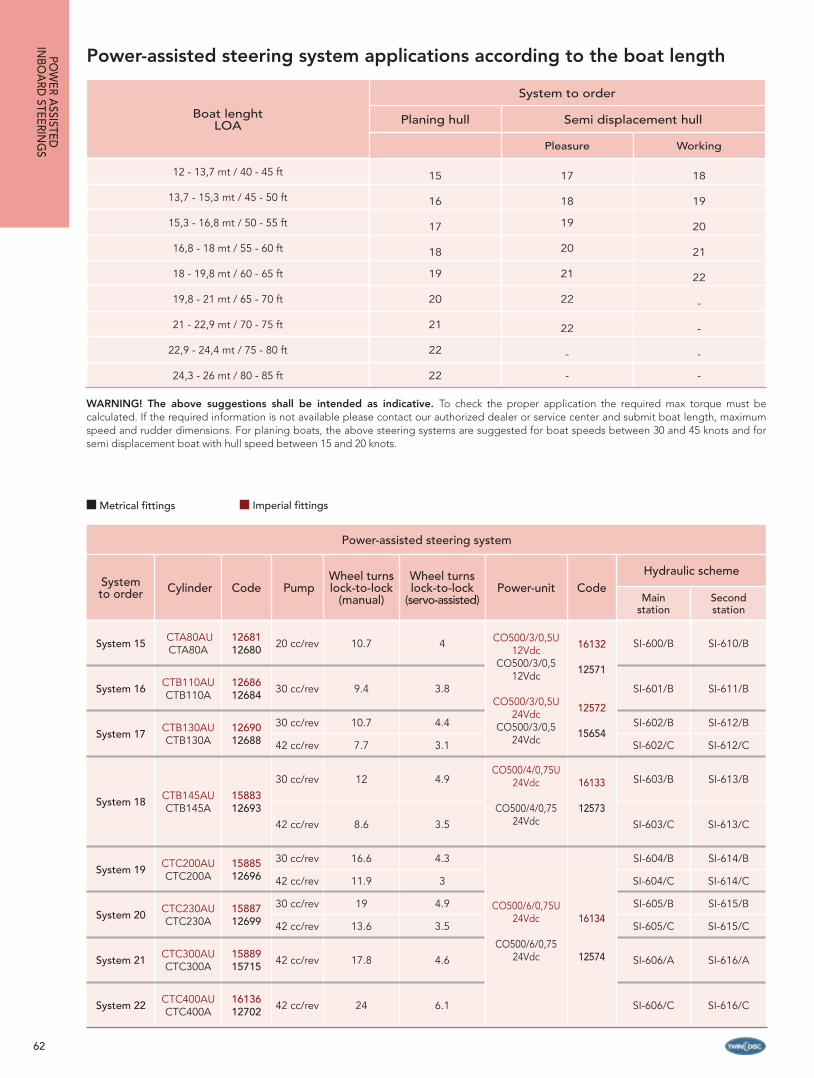
62
Power-assisted steering system applications according to the boat length
Power-assisted steering system
System to order Cylinder Code Pump
Wheel turns lock-to-lock
(manual)
Wheel turns lock-to-lock
(servo-assisted)Power-unit Code
Hydraulic scheme
Main station
Second station
System 15 CTA80AU CTA80A
1268112680 20 cc/rev 10.7 4 CO500/3/0,5U
12Vdc CO500/3/0,5
12Vdc
CO500/3/0,5U 24Vdc
CO500/3/0,5 24Vdc
16132
12571
12572
15654
SI-600/B SI-610/B
System 16 CTB110AU CTB110A
1268612684 30 cc/rev 9.4 3.8 SI-601/B SI-611/B
System 17 CTB130AU CTB130A
1269012688
30 cc/rev 10.7 4.4 SI-602/B SI-612/B
42 cc/rev 7.7 3.1 SI-602/C SI-612/C
System 18 CTB145AU CTB145A
1588312693
30 cc/rev 12 4.9CO500/4/0,75U
24Vdc
CO500/4/0,7524Vdc
16133
12573
SI-603/B SI-613/B
42 cc/rev 8.6 3.5 SI-603/C SI-613/C
System 19 CTC200AU CTC200A
1588512696
30 cc/rev 16.6 4.3
CO500/6/0,75U 24Vdc
CO500/6/0,75 24Vdc
16134
12574
SI-604/B SI-614/B
42 cc/rev 11.9 3 SI-604/C SI-614/C
System 20 CTC230AU CTC230A
1588712699
30 cc/rev 19 4.9 SI-605/B SI-615/B
42 cc/rev 13.6 3.5 SI-605/C SI-615/C
System 21 CTC300AU CTC300A
1588915715 42 cc/rev 17.8 4.6 SI-606/A SI-616/A
System 22 CTC400AU CTC400A
1613612702 42 cc/rev 24 6.1 SI-606/C SI-616/C
WARNING! The above suggestions shall be intended as indicative. To check the proper application the required max torque must becalculated. If the required information is not available please contact our authorized dealer or service center and submit boat length, maximum speed and rudder dimensions. For planing boats, the above steering systems are suggested for boat speeds between 30 and 45 knots and for semi displacement boat with hull speed between 15 and 20 knots.
Boat lenghtLOA
System to order
Planing hull Semi displacement hull
Pleasure Working
12 - 13,7 mt / 40 - 45 ft 15 17 18
13,7 - 15,3 mt / 45 - 50 ft 16 18 19
15,3 - 16,8 mt / 50 - 55 ft 17 19 20
16,8 - 18 mt / 55 - 60 ft 18 20 21
18 - 19,8 mt / 60 - 65 ft 19 21 22
19,8 - 21 mt / 65 - 70 ft 20 22 -
21 - 22,9 mt / 70 - 75 ft 21 22 -
22,9 - 24,4 mt / 75 - 80 ft 22 - -
24,3 - 26 mt / 80 - 85 ft 22 - -
POW
ER ASSISTED
INBO
ARD
STEERING
S
Metrical fittings Imperial fittings

63
POW
ER A
SSIS
TED
INBO
ARD
STE
ERIN
GS
Components Model Code Q.ty
Cylinder CTA80AUCTA80A
1268112680 1
Helm pump P20BAPP20BA
2117316192 1
Fittings for single station
1278413685
21
Electro-hydraulic power unit
CO500/3/0,5U 12 VdcCO500/3/0,5 12 Vdc
CO500/3/0,5U 24 VdcCO500/3/0,5 24 Vdc
1613212571
1257215654
1
Hydraulic oil VG22 21334 3
In case of a second station please add:
2° station helm pump P20BAPP20BA
2117316192
1
Fittings kit for additional station
2337623942 1
Hydraulic oil VG22 21334 1
Components Model Code Q.ty
Cylinder CTB110AUCTB110A
1268612684 1
Helm pump P30BAPP30BA
2117416193 1
Fittings for single station
1278413685
21
Electro-hydraulic power unit
CO500/3/0,5U 12 VdcCO500/3/0,5 12 Vdc
CO500/3/0,5U 24 VdcCO500/3/0,5 24 Vdc
1613212571
1257215654
1
Hydraulic oil VG22 21334 3
In case of a second station please add:
2° station helm pump P30BAPP30BA
2117416193 1
Fittings kit for additional station
2337623942 1
Hydraulic oil VG22 21334 1
System 15 System 16
Choose combination between pump and cylinder according to the wished number of wheel turns lock-to-lock.Note: the requested effort on the steering wheel is inversely proportional to the wheel turns number lock-to-lock:• less wheel turns, more effort • more wheel turns, less effort
HELM PUMP
(*)P20BAP Cod. 21173 P20BA Cod. 16192
(*)P30BAP Cod. 21174P30BA Cod. 16193
(*)P42BAP Cod. 21175 P42BA Cod. 16194
CY
LIN
DE
R CTA80AU - Cod. / Part # 12681CTA80A - Cod. / Part # 12680
No. of wheel turnsManual: 10,7Servo-control system: 4,0Suggested min hose (**)Tiller: 200 mm / 7.8 in.Angle: 35° + 35° Torque: 107,36 Kgm / 92,97 lb.in.Min. wheel diam: 350 mm - 13,77 in.
CTB110AU - Cod. / Part # 12686CTB110A - Cod. / Part # 12684
No. of wheel turnsManual: 9,4Servo-control system: 3,8Suggested min hose (**)Tiller: 153 mm / 6.0 in.Angle: 35° + 35° Torque: 140. 85 Kgm / 121,97 lb.in.Min. wheel diam: 350 mm - 13,77 in.
(*) For more details, see the basic helm section on page 11 and choose the desired mounting confi guration.(**) For the choice of the hydraulic hose, please see the relative scheme.
Pump-cylinder combination
Metrical fittings Imperial fittings
Responsiveness
SLOW MEDIUM FAST
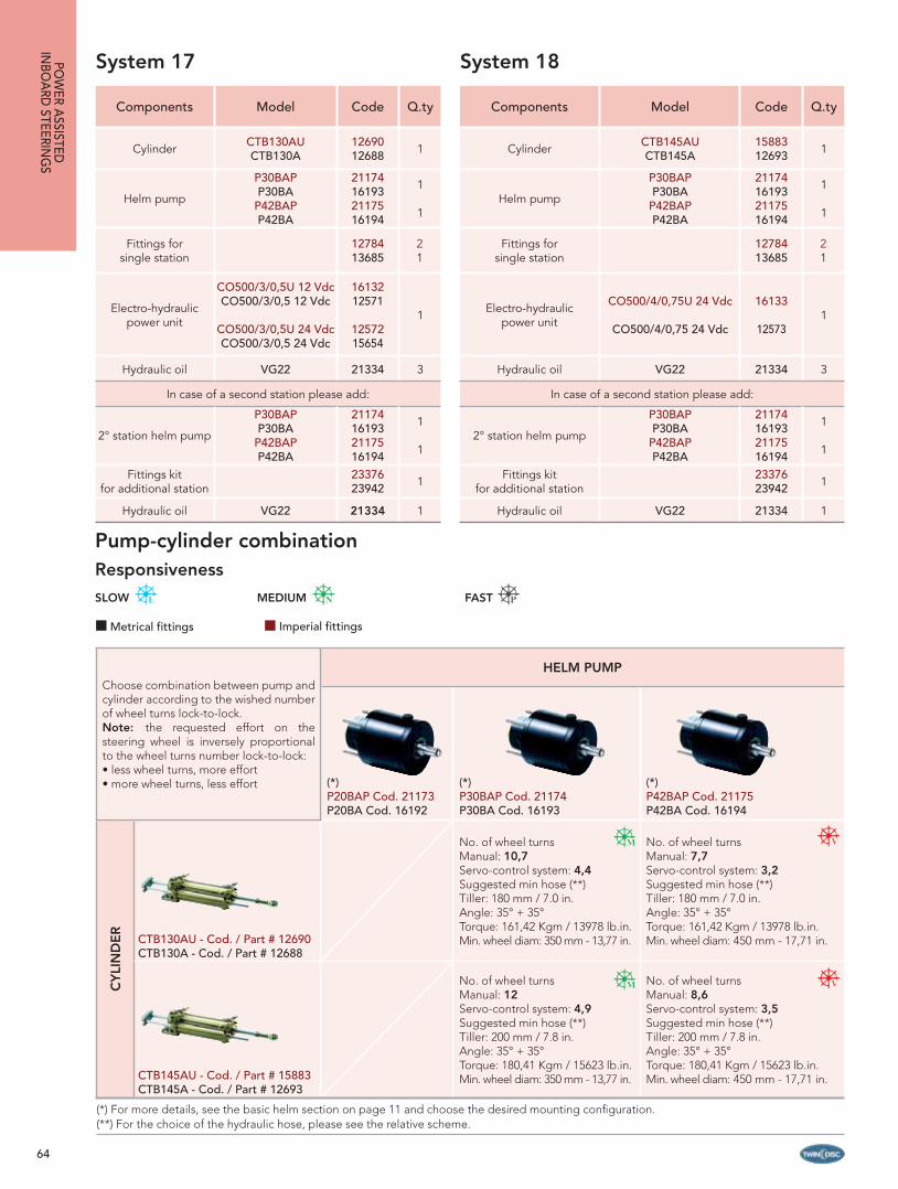
64
Components Model Code Q.ty
Cylinder CTB130AUCTB130A
1269012688 1
Helm pump
P30BAPP30BA
P42BAPP42BA
21174161932117516194
1
1
Fittings for single station
1278413685
21
Electro-hydraulic power unit
CO500/3/0,5U 12 VdcCO500/3/0,5 12 Vdc
CO500/3/0,5U 24 VdcCO500/3/0,5 24 Vdc
1613212571
1257215654
1
Hydraulic oil VG22 21334 3
In case of a second station please add:
2° station helm pump
P30BAPP30BA
P42BAPP42BA
21174161932117516194
1
1
Fittings kit for additional station
2337623942 1
Hydraulic oil VG22 21334 1
Components Model Code Q.ty
Cylinder CTB145AUCTB145A
1588312693 1
Helm pump
P30BAPP30BA
P42BAPP42BA
21174161932117516194
1
1
Fittings for single station
1278413685
21
Electro-hydraulic power unit
CO500/4/0,75U 24 Vdc
CO500/4/0,75 24 Vdc
16133
125731
Hydraulic oil VG22 21334 3
In case of a second station please add:
2° station helm pump
P30BAPP30BA
P42BAPP42BA
21174161932117516194
1
1
Fittings kit for additional station
2337623942 1
Hydraulic oil VG22 21334 1
System 17 System 18
Choose combination between pump and cylinder according to the wished number of wheel turns lock-to-lock.Note: the requested effort on the steering wheel is inversely proportional to the wheel turns number lock-to-lock:• less wheel turns, more effort • more wheel turns, less effort
HELM PUMP
(*)P20BAP Cod. 21173 P20BA Cod. 16192
(*)P30BAP Cod. 21174P30BA Cod. 16193
(*)P42BAP Cod. 21175 P42BA Cod. 16194
CY
LIN
DE
R
CTB130AU - Cod. / Part # 12690CTB130A - Cod. / Part # 12688
No. of wheel turnsManual: 10,7Servo-control system: 4,4Suggested min hose (**)Tiller: 180 mm / 7.0 in.Angle: 35° + 35° Torque: 161,42 Kgm / 13978 lb.in.Min. wheel diam: 350 mm - 13,77 in.
No. of wheel turnsManual: 7,7Servo-control system: 3,2Suggested min hose (**)Tiller: 180 mm / 7.0 in.Angle: 35° + 35° Torque: 161,42 Kgm / 13978 lb.in.Min. wheel diam: 450 mm - 17,71 in.
CTB145AU - Cod. / Part # 15883CTB145A - Cod. / Part # 12693
No. of wheel turnsManual: 12Servo-control system: 4,9Suggested min hose (**)Tiller: 200 mm / 7.8 in.Angle: 35° + 35° Torque: 180,41 Kgm / 15623 lb.in.Min. wheel diam: 350 mm - 13,77 in.
No. of wheel turnsManual: 8,6Servo-control system: 3,5Suggested min hose (**)Tiller: 200 mm / 7.8 in.Angle: 35° + 35° Torque: 180,41 Kgm / 15623 lb.in.Min. wheel diam: 450 mm - 17,71 in.
(*) For more details, see the basic helm section on page 11 and choose the desired mounting confi guration.(**) For the choice of the hydraulic hose, please see the relative scheme.
POW
ER ASSISTED
INBO
ARD
STEERING
S
Pump-cylinder combinationResponsiveness
SLOW MEDIUM FAST
Metrical fittings Imperial fittings
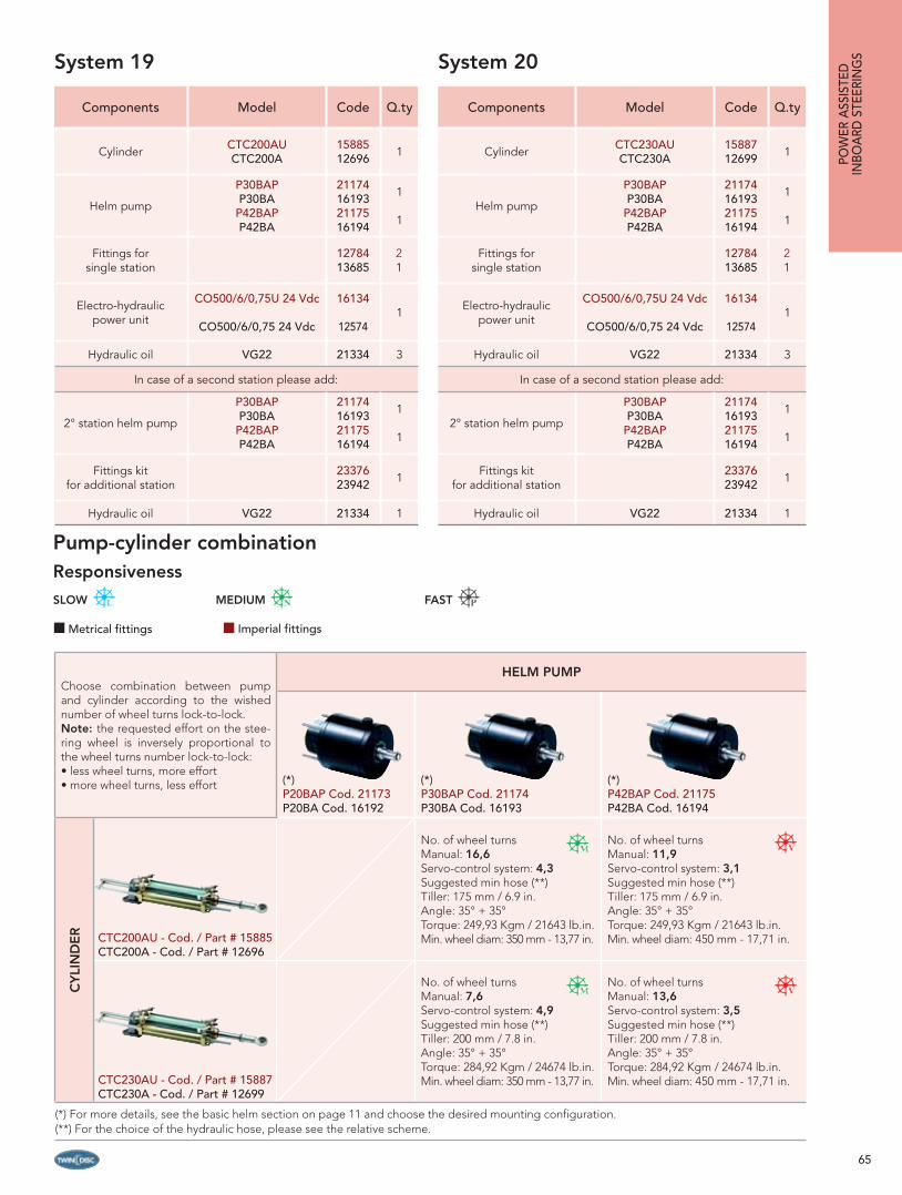
65
Components Model Code Q.ty
Cylinder CTC200AUCTC200A
1588512696 1
Helm pump
P30BAPP30BA
P42BAPP42BA
21174161932117516194
1
1
Fittings for single station
1278413685
21
Electro-hydraulic power unit
CO500/6/0,75U 24 Vdc
CO500/6/0,75 24 Vdc
16134
125741
Hydraulic oil VG22 21334 3
In case of a second station please add:
2° station helm pump
P30BAPP30BA
P42BAPP42BA
21174161932117516194
1
1
Fittings kit for additional station
2337623942 1
Hydraulic oil VG22 21334 1
Components Model Code Q.ty
Cylinder CTC230AUCTC230A
1588712699 1
Helm pump
P30BAPP30BA
P42BAPP42BA
21174161932117516194
1
1
Fittings for single station
1278413685
21
Electro-hydraulic power unit
CO500/6/0,75U 24 Vdc
CO500/6/0,75 24 Vdc
16134
125741
Hydraulic oil VG22 21334 3
In case of a second station please add:
2° station helm pump
P30BAPP30BA
P42BAPP42BA
21174161932117516194
1
1
Fittings kit for additional station
2337623942 1
Hydraulic oil VG22 21334 1
System 19 System 20
Choose combination between pump and cylinder according to the wished number of wheel turns lock-to-lock.Note: the requested effort on the stee-ring wheel is inversely proportional to the wheel turns number lock-to-lock:• less wheel turns, more effort • more wheel turns, less effort
HELM PUMP
(*)P20BAP Cod. 21173 P20BA Cod. 16192
(*)P30BAP Cod. 21174P30BA Cod. 16193
(*)P42BAP Cod. 21175 P42BA Cod. 16194
CY
LIN
DE
R CTC200AU - Cod. / Part # 15885CTC200A - Cod. / Part # 12696
No. of wheel turnsManual: 16,6Servo-control system: 4,3Suggested min hose (**)Tiller: 175 mm / 6.9 in.Angle: 35° + 35° Torque: 249,93 Kgm / 21643 lb.in.Min. wheel diam: 350 mm - 13,77 in.
No. of wheel turnsManual: 11,9Servo-control system: 3,1Suggested min hose (**)Tiller: 175 mm / 6.9 in.Angle: 35° + 35° Torque: 249,93 Kgm / 21643 lb.in.Min. wheel diam: 450 mm - 17,71 in.
CTC230AU - Cod. / Part # 15887CTC230A - Cod. / Part # 12699
No. of wheel turnsManual: 7,6Servo-control system: 4,9Suggested min hose (**)Tiller: 200 mm / 7.8 in.Angle: 35° + 35° Torque: 284,92 Kgm / 24674 lb.in.Min. wheel diam: 350 mm - 13,77 in.
No. of wheel turnsManual: 13,6Servo-control system: 3,5Suggested min hose (**)Tiller: 200 mm / 7.8 in.Angle: 35° + 35° Torque: 284,92 Kgm / 24674 lb.in.Min. wheel diam: 450 mm - 17,71 in.
(*) For more details, see the basic helm section on page 11 and choose the desired mounting confi guration.(**) For the choice of the hydraulic hose, please see the relative scheme.
POW
ER A
SSIS
TED
INBO
ARD
STE
ERIN
GS
Pump-cylinder combinationResponsiveness
SLOW MEDIUM FAST
Metrical fittings Imperial fittings

66
Components Model Code Q.ty
Cylinder CTC300AUCTC300A
1588915715 1
Helm pump P42BAPP42BA
2117516194 1
Fittings for single station
1278413685
21
Electro-hydraulic power unit
CO500/6/0,75U 24 Vdc
CO500/6/0,75 24 Vdc
16134
125741
Hydraulic oil VG22 21334 3
In case of a second station please add:
2° station helm pump P42BAPP42BA
2117516194 1
Fittings kit for additional station
2394423943 1
Hydraulic oil VG22 21334 1
Components Model Code Q.ty
Cylinder CTC400AUCTC400A
1613612702 1
Helm pump P42BAPP42BA
2117516194 1
Fittings for single station
1278413685
21
Electro-hydraulic power unit
CO500/6/0,75U 24 Vdc
CO500/6/0,75 24 Vdc
16134
125741
Hydraulic oil VG22 21334 3
In case of a second station please add:
2° station helm pump P42BAPP42BA
2117516194 1
Fittings kit for additional station
2394423943 1
Hydraulic oil VG22 21334 1
System 21 System 22
Choose combination between pump and cylinder according to the wished number of wheel turns lock-to-lock.Note: the requested effort on the stee-ring wheel is inversely proportional to the wheel turns number lock-to-lock:• less wheel turns, more effort • more wheel turns, less effort
HELM PUMP
(*)P20BAP Cod. 21173 P20BA Cod. 16192
(*)P30BAP Cod. 21174P30BA Cod. 16193
(*)P42BAP Cod. 21175 P42BA Cod. 16194
CY
LIN
DE
R CTC300AU - Cod. / Part # 15889CTC300A - Cod. / Part # 15715
No. of wheel turnsManual: 17,8Servo-control system: 4,6Suggested min hose (**)Tiller: 260 mm / 10,2 in.Angle: 35° + 35° Torque: 374,89 Kgm / 32465 lb.in.Min. wheel diam: 450 mm - 17,71 in.
CTC400AU - Cod. / Part # 16136CTC400A - Cod. / Part # 12702
No. of wheel turnsManual: 24,0Servo-control system: 6,1Suggested min hose (**)Tiller: 350mm / 13,7 in.Angle: 35° + 35° Torque: 499,85 Kgm / 43287 lb.in.Min. wheel diam: 450 mm - 17,71 in.
(*) For more details, see the basic helm section on page 11 and choose the desired mounting confi guration.(**) For the choice of the hydraulic hose, please see the relative scheme.
POW
ER ASSISTED
INBO
ARD
STEERING
S
Pump-cylinder combinationResponsiveness
SLOW MEDIUM FAST
Metrical fittings Imperial fittings

67
POW
ER A
SSIS
TED
INBO
ARD
STE
ERIN
G C
ILYN
DER
S
GLF
M
CB
H
A
D
D1
E
35° 35°T
SQ
N
R PU
Technical specifi cations
Model Code Stroke Torque Thrust at 70 bar - 1000 psi Volume Tiller Angle Thread Weight
CTA80AUCTA80A
1268112680
228 mm 107.33 Kgm 659,4 Kgf 214.78 cc 200 mm35° + 35° 1/4”NPTF - 3/8” O.D.
G1/4 - hose d. 10
5,5 Kg
9.0 in 9297 lb.in. 1453 lbf 13.11 cu.in 7,8 in. 12,13 lb
Dimensions
Model Stroke A B C D D1 E F G H L M N P Q R S T U
CTA80AUCTA80A
228 mm
741 mm
578mm
162mm
20mm
14 mm
19,05 mm
40mm
130mm
360mm
45mm
120mm
60mm
125 mm
40mm
105mm
8,5mm
200mm
165 mm
9,0 in.
29,17 in.
22,77 in.
6,38 in.
0,79 in.
0,55 in.
3/4 in.
1,57 in.
5,11 in.
13,17 in.
1,77 in.
4,72 in.
2,36in.
4,92in.
1,57 in.
4,13in.
0.33 in.
7,87in.
6,5in.
Power-assisted inboard steering cylinders Series CTA_A
Technical specifi cations
Main features
Cylinder body in anodized aluminumPiston rod in stainless steel for a high corrosion resistanceAdjustable base either horizontally or verticallySupplied with bleeders Meets ABYC standards
Note: the power-assisted inboard steering cylinders mod CTA_A are not suitable for installations on racing boats.
Metrical fittings Imperial fittings
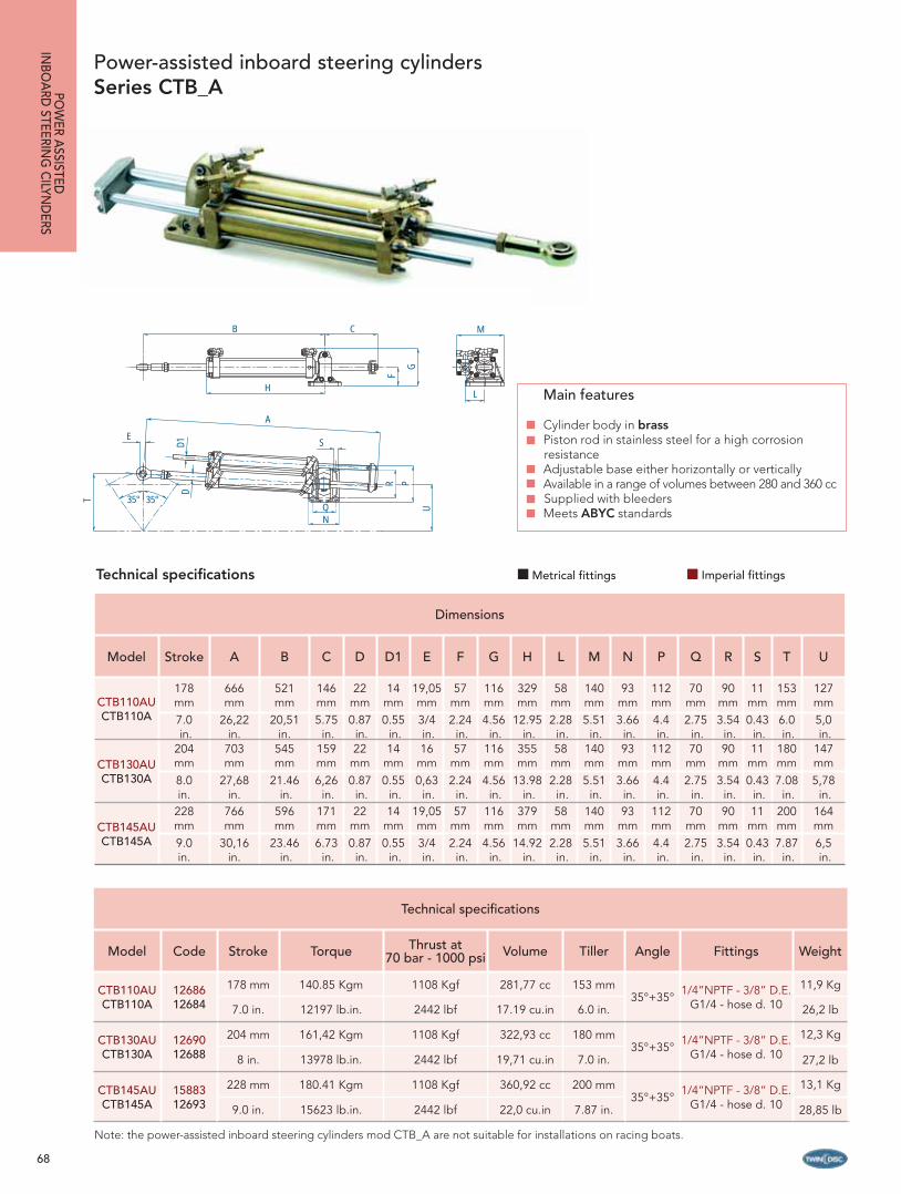
68
B C
HF
G
M
L
E
35°35°T
DD1
A
S
R P
UQN
Dimensions
Model Stroke A B C D D1 E F G H L M N P Q R S T U
CTB110AUCTB110A
178 mm
666 mm
521 mm
146 mm
22 mm
14 mm
19,05mm
57mm
116mm
329mm
58mm
140mm
93mm
112mm
70mm
90mm
11mm
153mm
127 mm
7.0 in.
26,22 in.
20,51 in.
5.75 in.
0.87 in.
0.55 in.
3/4 in.
2.24 in.
4.56 in.
12.95 in.
2.28 in.
5.51 in.
3.66 in.
4.4 in.
2.75 in.
3.54 in.
0.43 in.
6.0 in.
5,0 in.
CTB130AUCTB130A
204 mm
703 mm
545mm
159mm
22mm
14 mm
16mm
57mm
116mm
355mm
58mm
140mm
93mm
112mm
70mm
90mm
11mm
180mm
147 mm
8.0 in.
27,68 in.
21.46 in.
6,26 in.
0.87 in.
0.55 in.
0,63 in.
2.24 in.
4.56 in.
13.98 in.
2.28 in.
5.51 in.
3.66 in.
4.4 in.
2.75 in.
3.54 in.
0.43 in.
7.08 in.
5,78 in.
CTB145AUCTB145A
228 mm
766 mm
596mm
171mm
22mm
14 mm
19,05mm
57mm
116mm
379mm
58mm
140mm
93mm
112mm
70mm
90mm
11mm
200mm
164 mm
9.0 in.
30,16 in.
23.46 in.
6.73 in.
0.87 in.
0.55 in.
3/4 in.
2.24 in.
4.56 in.
14.92 in.
2.28 in.
5.51 in.
3.66 in.
4.4 in.
2.75 in.
3.54 in.
0.43 in.
7.87 in.
6,5 in.
Technical specifi cations
Model Code Stroke Torque Thrust at 70 bar - 1000 psi Volume Tiller Angle Fittings Weight
CTB110AUCTB110A
1268612684
178 mm 140.85 Kgm 1108 Kgf 281,77 cc 153 mm35°+35° 1/4”NPTF - 3/8” D.E.
G1/4 - hose d. 10
11,9 Kg
7.0 in. 12197 lb.in. 2442 lbf 17.19 cu.in 6.0 in. 26,2 lb
CTB130AUCTB130A
1269012688
204 mm 161,42 Kgm 1108 Kgf 322,93 cc 180 mm35°+35° 1/4”NPTF - 3/8” D.E.
G1/4 - hose d. 10
12,3 Kg
8 in. 13978 lb.in. 2442 lbf 19,71 cu.in 7.0 in. 27,2 lb
CTB145AUCTB145A
1588312693
228 mm 180.41 Kgm 1108 Kgf 360,92 cc 200 mm35°+35° 1/4”NPTF - 3/8” D.E.
G1/4 - hose d. 10
13,1 Kg
9.0 in. 15623 lb.in. 2442 lbf 22,0 cu.in 7.87 in. 28,85 lb
Power-assisted inboard steering cylinders Series CTB_APO
WER A
SSISTEDIN
BOA
RD STEERIN
G C
ILYND
ERS
Main features
Cylinder body in brass Piston rod in stainless steel for a high corrosion resistanceAdjustable base either horizontally or vertically Available in a range of volumes between 280 and 360 cc Supplied with bleeders Meets ABYC standards
Note: the power-assisted inboard steering cylinders mod CTB_A are not suitable for installations on racing boats.
Technical specifi cations Metrical fittings Imperial fittings

69
M
L
C
F
G
B
H
EA
35° 35°
S
QN
R P
U
D1D
T
Technical specifi cations
Model Code Stroke Torque Thrust at 70 bar - 1000 psi Volume Tiller Angle Fittings Weight
CTC200AUCTC200A
1588512696
200 mm 249,93 Kgm 1750 Kgf 500,0 cc 175 mm35°+35°
1/4”NPTF - 3/8” D.E. for servo-control cylinder
1/4”NPTF - 1/2” D.E. for main cylinder
G1/4 - hose d. 10 e T - G1/2 - hose d. 10
16,8 Kg
7,87 in. 21643 lb.in. 3857 lbf 30.5 cu.in 6.9 in. 37,1 lb
CTC230AUCTC230A
1588712699
228 mm 284,92 Kgm 1750 Kgf 570,0 cc 200 mm35°+35°
1/4”NPTF - 3/8” D.E. for servo-control cylinder
1/4”NPTF - 1/2” D.E. for main cylinder
G1/4 - hose d. 10 e T - G1/2 - hose d. 10
19,2 Kg
9.0 in. 24674 lb.in. 3857 lbf 34,78 cu.in 7.87 in. 42,3 lb
CTC300AUCTC300A
1588915715
300 mm 374.89 Kgm 1750 Kgf 750,0 cc 260 mm35°+35°
1/4”NPTF - 3/8” D.E. for servo-control cylinder
1/4”NPTF - 1/2” D.E. for main cylinder
G1/4 - hose d. 10 e T - G1/2 - hose d. 10
21,8 Kg
11.81 in. 32465 lb.in. 3857 lbf 45.77 cu.in 10.2 in. 48,1 lb.
CTC400AUCTC400A
1613612702
400 mm 499.85 Kgm 1750 Kgf 1000,0 cc 350 mm35°+35°
1/4”NPTF - 3/8” D.E. for servo-control cylinder
1/4”NPTF - 1/2” D.E. for main cylinder
G1/4 - hose d. 10 e T - G1/2 - hose d. 10
26,8 Kg
15.75 in. 43287 lb.in. 3857 lbf 61,02 cu.in 13.7 in. 59 lb
Dimensions
Model Stroke A B C D D1 E F G H L M N P Q R S T U
CTC200AUCTC200A
200 mm
767mm
607mm
161mm
28 mm
14 mm
25 mm
55 mm
132,5mm
385mm
65 mm
162mm
100mm
140mm
72mm
112 mm
11 mm
175mm
143mm
7.87 in.
30.2in.
23.9in.
6.34in.
1,10in.
0,55in.
0,98in.
2,17in.
5,22in.
15,16in.
2,56in.
6,38in.
3,94in.
5,51in.
2,83in.
4,41in.
0,43in.
6,89in.
5,6in.
CTC230AUCTC230A
228 mm
823mm
649mm
175mm
28 mm
14 mm
25mm
55mm
132,5mm
413mm
65mm
162mm
100mm
140mm
72mm
112mm
11mm
200mm
164mm
9.0 in.
32.4in.
25.55in.
6.89in.
1,10in.
0,55in.
0,98in.
2,17in.
5,22in.
16,26in.
2,56in.
6,38in.
3,94in.
5,51in.
2,83in.
4,41in.
0,43in.
7,87in.
6,5in.
CTC300AUCTC300A
300 mm
967mm
757mm
211mm
28mm
14mm
25mm
55mm
132,5mm
485mm
65mm
162mm
100mm
140mm
72mm
112mm
11mm
260mm
215mm
11,81 in.
38in.
29.8in.
8.3in.
1,10in.
0,55in.
0,98in.
2,17in.
5,22in.
19,09in.
2,56in.
6,38in.
3,94in.
5,51in.
2,83in.
4,41in.
0,43in.
10,24in.
8,5in.
CTC400AUCTC400A
400 mm
1167mm
907mm
261mm
28mm
14mm
25mm
55mm
132,5mm
585mm
65mm
162mm
100mm
140mm
72mm
112mm
11mm
350mm
286mm
15.75 in.
46in.
35.7in.
10.27in.
1,10in.
0,55in.
0,98in.
2,17in.
5,22in.
23,0in.
2,56in.
6,38in.
3,94in.
5,51in.
2,83in.
4,41in.
0,43in.
13,78in.
11,3in.
Power-assisted inboard steering cylinders Serie CTC_A
POW
ER A
SSIS
TED
INBO
ARD
STE
ERIN
G C
ILYN
DER
S
Main features
Cylinder body in stainless steel and brass paintedPiston rod in stainless steel for a high corrosion resistanceAdjustable base either horizontally or verticallyAvailable in a range of volumes between 500 and 1000 cc Supplied with bleeders Meets ABYC standards
Note: the power-assisted inboard steering cylinders mod CTC_A are not suitable for installations on racing boats.
Technical specifi cations Metrical fittings Imperial fittings

70
POW
ER ASSISTED
ELECTRO
HYD
RAU
LIC PO
WER U
NITS
POWER-ASSISTED ELECTRO-HYDRAULIC POWER UNITS
The BCS power-assisted electro-hydraulic power unit ensures the best performance of the steering system: it guarantees all the power necessary to the steering system and is completely independent from the boat’s main engines.
Composition.Extremely compact, it is composed of:- a hard plastic tank, allowing the oil level to be easily checked;- an electric motor;- a hydraulic pump; - a fi lter group; - all necessary valves for both the steering operation and safety
(non return valves, relief valves, servo-control groups, pressure adjusters, etc.).
This power unit is provided with:
- an interface for the auto-pilot;- a special device for automatic fi lling of the system makes the bleeding procedure easy and fast (more details at page 55 “Auto-pilot power units with automatic fi lling”); - a speed adjuster, which can be adapted to any auto-pilot manufacturer’s requirements.
The servo-control power unit can be excluded from the steering system at any time by pressing the red button mounted on the unit top. This immediately converts the system into a manual steering system (please, also see the steering working principle on page 61).
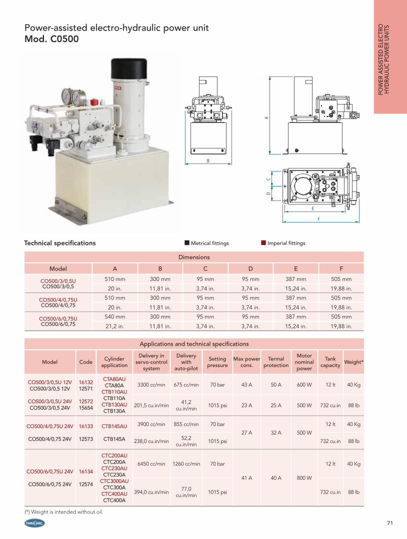
71
Dimensions
Model A B C D E F
CO500/3/0,5UCO500/3/0,5
510 mm 300 mm 95 mm 95 mm 387 mm 505 mm
20 in. 11,81 in. 3,74 in. 3,74 in. 15,24 in. 19,88 in.
CO500/4/0,75UCO500/4/0,75
510 mm 300 mm 95 mm 95 mm 387 mm 505 mm
20 in. 11,81 in. 3,74 in. 3,74 in. 15,24 in. 19,88 in.
CO500/6/0,75UCO500/6/0,75
540 mm 300 mm 95 mm 95 mm 387 mm 505 mm
21,2 in. 11,81 in. 3,74 in. 3,74 in. 15,24 in. 19,88 in.
Applications and technical specifi cations
Model Code Cylinder application
Delivery in servo-control
system
Delivery with
auto-pilot
Setting pressure
Max power cons.
Termal protection
Motor nominal power
Tank capacity Weight*
CO500/3/0,5U 12VCO500/3/0,5 12V
CO500/3/0,5U 24VCO500/3/0,5 24V
1613212571
1257215654
CTA80AUCTA80A
CTB110AUCTB110A
CTB130AUCTB130A
3300 cc/min 675 cc/min 70 bar 43 A 50 A 600 W 12 lt 40 Kg
201,5 cu.in/min 41,2 cu.in/min 1015 psi 23 A 25 A 500 W 732 cu.in 88 lb
CO500/4/0,75U 24V
CO500/4/0,75 24V
16133
12573
CTB145AU
CTB145A
3900 cc/min 855 cc/min 70 bar
27 A 32 A 500 W
12 lt 40 Kg
238,0 cu.in/min 52,2 cu.in/min 1015 psi 732 cu.in 88 lb
CO500/6/0,75U 24V
CO500/6/0,75 24V
16134
12574
CTC200AU CTC200A
CTC230AU CTC230A
CTC3000AU CTC300A
CTC400AU CTC400A
6450 cc/min 1260 cc/min 70 bar
41 A 40 A 800 W
12 lt 40 Kg
394,0 cu.in/min 77,0 cu.in/min 1015 psi 732 cu.in 88 lb
Power-assisted electro-hydraulic power unit Mod. C0500
Technical specifi cations
B
AC
D
E
F
POW
ER A
SSIS
TED
ELE
CTR
OH
YDRA
ULI
C P
OW
ER U
NIT
S
(*) Weight is intended without oil.
Metrical fittings Imperial fittings
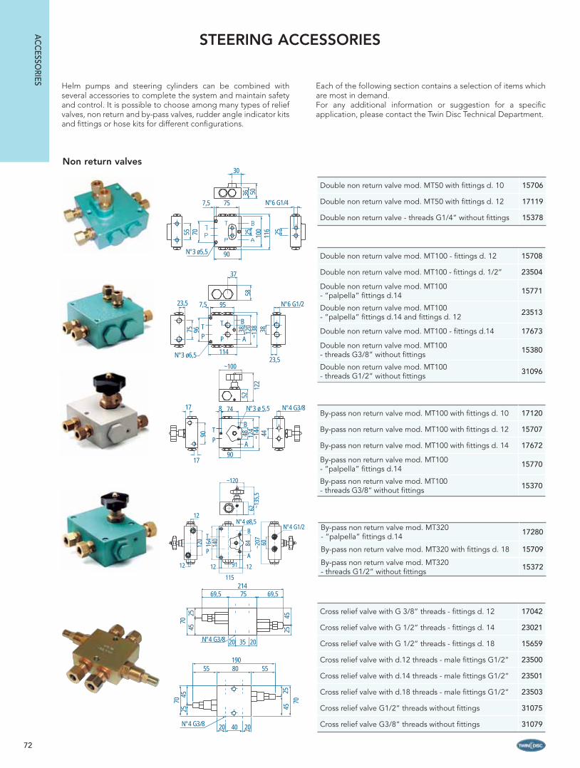
72
30
36 50
N°6 G1/4
2555
7,5 7570
N°3 ø5,5 9025 10
011
6
~120
62 ~135
,5~2
07 60
N°4 G1/2
12
12
120
N°4 ø8,5
T
P
B
A
84164
140
12 1291
115
STEERING ACCESSORIES
75 96
23,5
N°3 ø6,5
PT
P
T
A
B
114
957,5
38 120
~138 38
23,5
N°6 G1/2
37
58
90
17
17
PT
90
748
A
B
N°3 ø 5,5
48 124
~144 44
N°4 G3/8
~100
52
122
Non return valves
Double non return valve mod. MT100 - fi ttings d. 12 15708
Double non return valve mod. MT100 - fi ttings d. 1/2” 23504
Double non return valve mod. MT100 - “palpella” fi ttings d.14 15771
Double non return valve mod. MT100 - “palpella” fi ttings d.14 and fi ttings d. 12 23513
Double non return valve mod. MT100 - fi ttings d.14 17673
Double non return valve mod. MT100 - threads G3/8” without fi ttings 15380
Double non return valve mod. MT100 - threads G1/2” without fi ttings 31096
By-pass non return valve mod. MT100 with fi ttings d. 10 17120
By-pass non return valve mod. MT100 with fi ttings d. 12 15707
By-pass non return valve mod. MT100 with fi ttings d. 14 17672
By-pass non return valve mod. MT100 - “palpella” fi ttings d.14 15770
By-pass non return valve mod. MT100 - threads G3/8” without fi ttings 15370
By-pass non return valve mod. MT320 - “palpella” fi ttings d.14 17280
By-pass non return valve mod. MT320 with fi ttings d. 18 15709
By-pass non return valve mod. MT320 - threads G1/2” without fi ttings 15372
Cross relief valve with G 3/8” threads - fi ttings d. 12 17042
Cross relief valve with G 1/2” threads - fi ttings d. 14 23021
Cross relief valve with G 1/2” threads - fi ttings d. 18 15659
Cross relief valve with d.12 threads - male fi ttings G1/2” 23500
Cross relief valve with d.14 threads - male fi ttings G1/2” 23501
Cross relief valve with d.18 threads - male fi ttings G1/2” 23503
Cross relief valve G1/2” threads without fi ttings 31075
Cross relief valve G3/8” threads without fi ttings 31079
Helm pumps and steering cylinders can be combined with several accessories to complete the system and maintain safety and control. It is possible to choose among many types of relief valves, non return and by-pass valves, rudder angle indicator kits and fi ttings or hose kits for different confi gurations.
Each of the following section contains a selection of items which are most in demand.For any additional information or suggestion for a specifi c application, please contact the Twin Disc Technical Department.
21469,5 75 69,5
20 2035N°4 G3/8
7025
45 2545
19055 80 55
20 40 20N°4 G3/8
7045
25
7045
25
Double non return valve mod. MT50 with fi ttings d. 10 15706
Double non return valve mod. MT50 with fi ttings d. 12 17119
Double non return valve - threads G1/4” without fi ttings 15378
AC
CESSO
RIES

73
Rudder angle indicator set
Steering hydraulic oil
Steering hydraulic oil type ISO VG 22 – 1 litre bottle cod. 21334
Electric by-pass 12Vdc for auto-pilot power units mod. CO2-CO2/3-CO3 - fi ttings for d. 10 hose 12140
Electric by-pass 24Vdc for auto-pilot power units mod. CO2-CO2/3-CO3 - fi ttings for d. 10 hose 12141
Electric by-pass 12Vdc for auto-pilot power units mod. CO4 - fi ttings for d. 10 hose 15713
Electric by-pass 24Vdc for auto-pilot power units mod. CO4 - fi ttings for d. 10 hose 15714
Electric by-pass 12Vdc for auto-pilot power units mod. CO2-CO2/3-CO3 - fi ttings for d. 3/8” hose 21330
Electric by-pass 24vdc for auto-pilot power units mod. CO2-CO2/3-CO3 - fi ttings for d. 3/8” hose 21331
Electric by-pass 12Vdc for auto-pilot power units mod. CO4 - fi ttings for d. 1/2” hose 21332
Electric by-pass 24Vdc for auto-pilot power units mod. CO4 - fi ttings for d. 1/2” hose 21333
Electric by-pass for auto-pilot power units
Single-station rudder angle indicator kit cod. 13608
Double-station rudder angle indicator kit cod. 13609
ø37 mm (1,45”)
G 1/4”
ø20 mm (0,78”)
20 m
m M
AX (
0,78
”)ø12 mm (0,47”)
Filling kit helm pumpIn all those cases where the helm pump mounting confi guration does not allow easy access to the fi lling cap, which is placed on the helm top, (i.e. rear mounting or tilt mounting) a fi lling kit should be purchased. This kit is directly screwed on the helm cap in order to move the fi lling point to a new one which is accessed more easily by means of a hose prolongation.
MK100 cod. 18599
Note: the choice of the electric by-pass depends on cylinder volume and power unit displacement, as shown on table at page 58.
AC
CES
SORI
ES
BCS steering range contains a kit of rudder angle indicators and transmitters: a simple and precise system that allows to control the exact position of the rudder and provides higher level of safety.
This set includes: rudder angle indicators which has a range from 0° to + 40°, as well as a kit of angle transmitters, which comprises lever mechanism, a ball joint together with a rod to connect to the tiller.
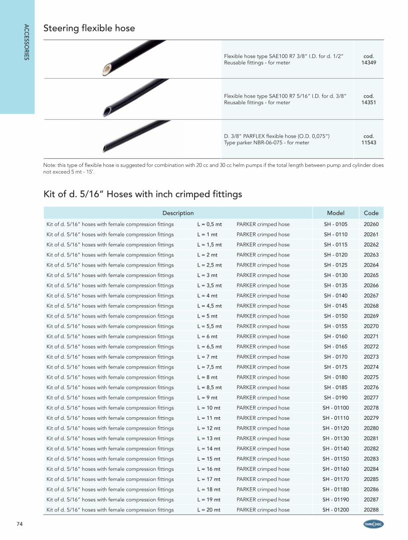
74
Flexible hose type SAE100 R7 3/8” I.D. for d. 1/2” Reusable fi ttings - for meter
cod. 14349
Flexible hose type SAE100 R7 5/16” I.D. for d. 3/8” Reusable fi ttings - for meter
cod. 14351
D. 3/8” PARFLEX fl exible hose (O.D. 0,075”) Type parker NBR-06-075 - for meter
cod. 11543
Steering flexible hose
Description Model Code
Kit of d. 5/16” hoses with female compression fi ttings L = 0,5 mt PARKER crimped hose SH - 0105 20260
Kit of d. 5/16” hoses with female compression fi ttings L = 1 mt PARKER crimped hose SH - 0110 20261
Kit of d. 5/16” hoses with female compression fi ttings L = 1,5 mt PARKER crimped hose SH - 0115 20262
Kit of d. 5/16” hoses with female compression fi ttings L = 2 mt PARKER crimped hose SH - 0120 20263
Kit of d. 5/16” hoses with female compression fi ttings L = 2,5 mt PARKER crimped hose SH - 0125 20264
Kit of d. 5/16” hoses with female compression fi ttings L = 3 mt PARKER crimped hose SH - 0130 20265
Kit of d. 5/16” hoses with female compression fi ttings L = 3,5 mt PARKER crimped hose SH - 0135 20266
Kit of d. 5/16” hoses with female compression fi ttings L = 4 mt PARKER crimped hose SH - 0140 20267
Kit of d. 5/16” hoses with female compression fi ttings L = 4,5 mt PARKER crimped hose SH - 0145 20268
Kit of d. 5/16” hoses with female compression fi ttings L = 5 mt PARKER crimped hose SH - 0150 20269
Kit of d. 5/16” hoses with female compression fi ttings L = 5,5 mt PARKER crimped hose SH - 0155 20270
Kit of d. 5/16” hoses with female compression fi ttings L = 6 mt PARKER crimped hose SH - 0160 20271
Kit of d. 5/16” hoses with female compression fi ttings L = 6,5 mt PARKER crimped hose SH - 0165 20272
Kit of d. 5/16” hoses with female compression fi ttings L = 7 mt PARKER crimped hose SH - 0170 20273
Kit of d. 5/16” hoses with female compression fi ttings L = 7,5 mt PARKER crimped hose SH - 0175 20274
Kit of d. 5/16” hoses with female compression fi ttings L = 8 mt PARKER crimped hose SH - 0180 20275
Kit of d. 5/16” hoses with female compression fi ttings L = 8,5 mt PARKER crimped hose SH - 0185 20276
Kit of d. 5/16” hoses with female compression fi ttings L = 9 mt PARKER crimped hose SH - 0190 20277
Kit of d. 5/16” hoses with female compression fi ttings L = 10 mt PARKER crimped hose SH - 01100 20278
Kit of d. 5/16” hoses with female compression fi ttings L = 11 mt PARKER crimped hose SH - 01110 20279
Kit of d. 5/16” hoses with female compression fi ttings L = 12 mt PARKER crimped hose SH - 01120 20280
Kit of d. 5/16” hoses with female compression fi ttings L = 13 mt PARKER crimped hose SH - 01130 20281
Kit of d. 5/16” hoses with female compression fi ttings L = 14 mt PARKER crimped hose SH - 01140 20282
Kit of d. 5/16” hoses with female compression fi ttings L = 15 mt PARKER crimped hose SH - 01150 20283
Kit of d. 5/16” hoses with female compression fi ttings L = 16 mt PARKER crimped hose SH - 01160 20284
Kit of d. 5/16” hoses with female compression fi ttings L = 17 mt PARKER crimped hose SH - 01170 20285
Kit of d. 5/16” hoses with female compression fi ttings L = 18 mt PARKER crimped hose SH - 01180 20286
Kit of d. 5/16” hoses with female compression fi ttings L = 19 mt PARKER crimped hose SH - 01190 20287
Kit of d. 5/16” hoses with female compression fi ttings L = 20 mt PARKER crimped hose SH - 01200 20288
Kit of d. 5/16” Hoses with inch crimped fittings
AC
CESSO
RIES
Note: this type of fl exible hose is suggested for combination with 20 cc and 30 cc helm pumps if the total length between pump and cylinder does not exceed 5 mt - 15’.

75
Description Model Code
Kit of d. 5/16” hoses L = 0,5 mt with 3/8” straight reusable fi ttings SH-0505 23098
Kit of d. 5/16” hoses L = 1 mt with 3/8” straight reusable fi ttings SH-0510 23099
Kit of d. 5/16” hoses L = 1,5 mt with 3/8” straight reusable fi ttings SH-0515 23100
Kit of d. 5/16” hoses L = 2 mt with 3/8” straight reusable fi ttings SH-0520 23101
Kit of d. 5/16” hoses L = 2,5 mt with 3/8” straight reusable fi ttings SH-0525 23102
Kit of d. 5/16” hoses L = 3 mt with 3/8” straight reusable fi ttings SH-0530 23103
Kit of d. 5/16” hoses L = 3,5 mt with 3/8” straight reusable fi ttings SH-0535 23104
Kit of d. 5/16” hoses L = 4 mt with 3/8” straight reusable fi ttings SH-0540 23105
Kit of d. 5/16” hoses L = 4,5 mt with 3/8” straight reusable fi ttings SH-0545 23106
Kit of d. 5/16” hoses L = 5 mt with 3/8” straight reusable fi ttings SH-0550 23107
Kit of d. 5/16” hoses L = 5,5 mt with 3/8” straight reusable fi ttings SH-0555 23108
Kit of d. 5/16” hoses L = 6 mt with 3/8” straight reusable fi ttings SH-0560 23109
Kit of d. 5/16” hoses L = 6,5 m with 3/8” straight reusable fi ttings SH-0565 23110
Kit of d. 5/16” hoses L = 7 mt with 3/8” straight reusable fi ttings SH-0570 23111
Kit of d. 5/16” hoses L = 7,5 mt with 3/8” straight reusable fi ttings SH-0575 23112
Kit of d. 5/16” hoses L = 8 mt with 3/8” straight reusable fi ttings SH-0580 23113
Kit of d. 5/16” hoses L = 8,5 mt with 3/8” straight reusable fi ttings SH-0585 23114
Kit of d. 5/16” hoses L = 9 mt with 3/8” straight reusable fi ttings SH-0590 23115
Kit of d. 5/16” hoses L = 10 mt with 3/8” straight reusable fi ttings SH-05100 23381
Kit of d. 5/16” hoses L = 11 mt with 3/8” straight reusable fi ttings SH-05110 23382
Kit of d. 5/16” hoses L = 12 mt with 3/8” straight reusable fi ttings SH-05120 23383
Kit of d. 5/16” hoses L = 13 mt with 3/8” straight reusable fi ttings SH-05130 23384
Kit of d. 5/16” hoses L = 14 mt with 3/8” straight reusable fi ttings SH-05140 23385
Kit of d. 5/16” hoses L = 15 mt with 3/8” straight reusable fi ttings SH-05150 23386
Kit of d. 5/16” hoses L = 16 mt with 3/8” straight reusable fi ttings SH-05160 23387
Kit of d. 5/16” hoses L = 17 mt with 3/8” straight reusable fi ttings SH-05170 23388
Kit of d. 5/16” hoses L = 18 mt with 3/8” straight reusable fi ttings SH-05180 23389
Kit of d. 5/16” hoses L = 19 mt with 3/8” straight reusable fi ttings SH-05190 23390
Kit of d. 5/16” hoses L = 20 mt with 3/8” straight reusable fi ttings SH-05200 23391
Kit of d. 5/16” hoses with inch reusable fittings
AC
CES
SORI
ES

76
Flexible hoses for heavy duty steering cylinders
Flexible hose SAE100 R1 1/2” with d.12 fi tting - G 1/2” female compression fi tting L = 0,6 mt single hose 11374
Flexible hose SAE100 R1 1/2” with d.12 fi tting - G 1/2” female compression fi tting L = 1 mt single hose 20954
Flexible hose SAE100 R1 1/2” with d.12 fi tting - G 1/2” female compression fi tting L = 1,5 mt single hose 22157
Flexible hose SAE100 R1 1/2” with d.14 fi tting - G 1/2” female compression fi tting L = 0,6 mt single hose 11371
Flexible hose SAE100 R1 1/2” - 1/2” male fi tting - G 1/2” female compression fi tting L = 1 mt single hose 23404
Flexible hose SAE100 R1 1/2” - 1/2” male fi tting - G 1/2” female compression fi tting L = 1,5 mt single hose 23405
Flexible hose SAE100 R1 3/8” - 3/8” male fi tting - G 3/8” female compression fi tting L = 0,6 mt single hose 23406
Flexible hose SAE100 R1 3/8” - 3/8” male fi tting - G 3/8” female compression fi tting L = 1 mt single hose 23407
Flexible hose SAE100 R1 3/8” - 3/8” male fi tting - G 3/8” female compression fi tting L = 1,5 mt single hose 23408
Fitting kit for outboard and inboard steerings
Fitting kit for double station pump BAP installations - fi ttings d. 3/8” 23376
Fitting kit for double station pump BAP installations - fi ttings 1/2” 23418
Fitting kit for single station pump BAP installations - fi ttings d. 3/8” 23377
Fitting kit for single station pump BAP installations - fi ttings d. 1/2” 23373
Fitting kit for double station pump BA - fi ttings d. 10 23487
Fitting kit for double station pump BA - fi ttings d. 12 23488
Fitting kit for single station pump BA with power unit - fi ttings d. 10 23489
Fitting kit for single station pump BA with power unit - fi ttings d. 12 23490
Fitting kit and bolts for pump installation - elbow fi tting 1/4 NPTF - hose 3/8” 17981
Fitting kit for double station P63 heavy duty pump installations - d.12 fi ttings 23492
Fitting kit for double station P63 and P89 heavy duty pump installations - d. 14 fi ttings 23493
Fitting kit for double station P63 and P89 heavy duty pump installations - d. 18 fi ttings 23452
Fitting kit for double station P105, P151 and P191 heavy duty pump installations - d. 18 fi ttings 23518
Fitting kit for heavy duty steerings
Ball-cock with lever - 1/2” female - 1/2” female fi ttings 14524
Ball-cock with lever - 1/4” female - 1/4” female fi ttings 14526
Ball-cock with lever - 3/8” female - 3/8” female fi ttings 14529
Ball-cock with lever
By-pass
Manual by-pass with 1/4” cocks and fi ttings for d. 3/8” hose 23186
Manual by-pass with 1/4” cocks and fi ttings for d. 10 hose 12216
Manual by-pass with 3/8” cocks and fi ttings for d. 12 hose 16968
Manual by-pass with 3/8” cocks and fi ttings for d. 1/2” hose 23480
Manual by-pass with 1/2” cocks and fi ttings for d. 14 hose 23036
Manual by-pass with 1/2” cocks and fi ttings for d. 18 hose 23037
High pressure by-pass with cocks of 1/2” 12132*
Manual high pressure by-pass with cocks of 1/2” type B 12134
AC
CESSO
RIES
(*) Available in different confi gurations. For more details please contact Twin Disc Technical Department.

77
AC
CES
SORI
ESFitting kit for steering systems with auto-pilot power unit and automatic filling
Fitting kit for pump P63 and P89 single station and auto-pilot with automatic fi lling - hose d. 14 23511
Fitting kit for pump P63 single station and auto-pilot with automatic fi lling - hose d. 1/2” 23512
Fitting kit for pump P63 single station and auto-pilot with automatic fi lling - hose d. 12 23510
Fitting kit for pump P63 single station and auto-pilot - power unit CO4NR - hose d. 12 23514
Fitting kit for pump P63 single station and auto-pilot - power unit CO4NRU - hose d. 1/2” 23516
Fitting kit for pump P63 and P69 single station and auto-pilot - power unit CO4NR - hose d. 14 23515
Fitting kit for pump P63 and P69 single station and auto-pilot - power units CO7, CO16 - hose d. 18 23517
Fitting kit for pump P63 and P69 single station and auto-pilot - hose d. 14 23507
Fitting kit for pump P63 and P69 single station and auto-pilot - hose d. 18 23509
Fitting kit for pump P63 single station and auto-pilot - hose d. 1/2” 23508
Fitting kit for pump P63 single station and auto-pilot - hose d. 12 23506
Fitting kit for pump P105, P151, P191 single station and auto-pilot - hose d. 18 23520
Fitting kit for pump timoneria asservita doppio comando 1/4” NPTF hose d. 1/2” and fi lling hose d. 3/8” 23944
Fitting kit for pump power assisted steering system double station G 1/4” - hose d. 10 23942
Fitting kit for pump power assisted steering system double station G 1/4” hose d. 12 and fi lling hose d. 10 23943
Fitting kit for pump single station G 1/4” - hose d. 10 13685

78
AC
CESSO
RIES
Fittings
DescriptionCode
for zincplated
Code for brass
Code for chromium
plated
Seal kit and fi ttings for CTA cylinder bleeder 23048
Seal kit and fi ttings for CTB cylinder bleeder 23049
Seal kit and fi ttings for CTC cylinder bleeder 23050
Seal kit and fi ttings for power-assisted CTA_A cylinder bleeder 23051
Seal kit and fi ttings for power-assisted CTB_A cylinder bleeder 23052
Seal kit and fi ttings for power-assisted CTC_A cylinder bleeder 23053
Seal kit and fi ttings for CTAU and OB108-133 cylinder bleeder 23054
Seal kit and fi ttings for CTBU cylinder bleeder 23055
Seal kit and fi ttings for CTCU cylinder bleeder 23056
Seal kit and fi ttings for power-assisted CTA_AU cylinder bleeder 23057
Seal kit and fi ttings for power-assisted CTB_AU cylinder bleeder 23058
Seal kit and fi ttings for power-assisted CTC_AU cylinder bleeder 23059
Straight connection fi tting G1/2” - G1/2” 21199
Straight connection fi tting G3/8” - G3/8” 21198
Straight connection fi tting d. 10 hose - d. 10 hose 17038
Straight connection fi tting d. 12 hose - d. 12 hose 12877
Straight connection fi tting d. 14 hose - d. 14 hose 12879
Straight connection fi tting d. 16 hose - d. 16 hose 12880
Straight connection fi tting d. 18 hose - d. 18 hose 12881
Straight fi tting G 3/8” - d. 10 hose 12800 14358
Straight fi tting G 3/8” - d. 12 hose 12801 14359 12791
Straight fi tting G 3/8” - d. 14 hose 12802 14360
Straight fi tting G 3/8” - d. 18 hose 14361
Straight fi tting G 3/8” - d. 1/2” hose 12809
Straight fi tting G 1/2” - d. 14 hose 12793 12808
Straight fi tting G 1/2” - d. 16 hose 12794
Straight fi tting G 1/2” - d. 18 hose 12795 14355
Straight fi tting G 1/4” - d. 10 hose 14356
Straight fi tting G 1/4” - d. 12 hose 16043
Straight fi tting 1/4” NPTF - 1/2” hose 21077
Straight fi tting 1/4”NPTF - 3/8” hose 12784

79
DescriptionCode
for zincplated
Code for brass
Code for chromium
plated
Reduction G 3/8” male - G1/2” female 12836
Reduction G 3/8” male - G1/4” female 12851
Reduction G 1/2” male - G3/8” female 12844 12839
Reduction G 1/4” male - G3/8” female 12848 12826
Reduction G 1/2” male - 1/4”NPTF female 11211
Reduction G 1/4” male - 1/4”NPTF female 14352
Reduction 1/4” NPTF male - 3/8” NPTF female 23546
Straight reusable fi tting R7 5/16” - hose d. 10 15610
Straight reusable fi tting for R7 5/16” - hose d. 3/8” 15613
Straight reusable fi tting for R7 3/8” - hose d. 12 15720
Straight reusable fi tting for R7 3/8” - hose d. 1/2” 23477
Elbow reusable fi tting for R7 5/16” - hose d. 3/8” 23476
Elbow reusable fi tting for R7 5/16” - hose d. 10 15718
Elbow reusable fi tting for R7 3/8” - hose d. 12 15721
Tee fi tting d. 3/8” hose - 1/4” NPTF - hose d. 3/8” 14734
Tee fi tting d. 3/8” hose - 3/8” NPTF - hose d. 3/8” 20837
Tee fi tting d. 1/2” hose - 3/8” NPTF - hose d. 1/2” 14733
Tee fi tting d. 10 hose - G 1/4” - hose d. 10 14735
Tee fi tting d. 12 hose - G 3/8” - hose d. 12 14750
Tee fi tting d. 18 hose - G 1/2” - hose d. 18 22482
Tee fi tting d. 10 hose - G 1/4” - hose d. 10 14996+11795
Elbow fi tting 1/4” NPTF - hose d. 1/2” 20574
Elbow fi tting 1/4” NPTF - hose d. 3/8” 11676
Elbow fi tting G 1/4” - hose d. 10 11687 11678
Elbow fi tting G 1/4” - hose d. 12 11688
Equal Tee fi tting d. 3/8” - hose d. 3/8” 21092
Equal Tee fi tting d. 1/2” - hose d. 1/2” 21093
Equal Tee fi tting d. 10 - hose d. 10 14873 14874
Equal Tee fi tting d. 12 - hose d. 12 14882
Equal Tee fi tting d. 14 - hose d. 14 14877
Equal Tee fi tting d. 18 - hose d. 18 14878
AC
CES
SORI
ES

80
Position Description Code
1
Seal kit for OB133 and OB108 cylinders 20797
Seal kit for OB163SY cylinder 11514
2
Black side bracket for OB133 cylinder 12056
Black side bracket for OB108 cylinder 19297
3
Through-tube stainless steel rod for OB133 cylinder 11855
Through-tube stainless steel rod for OB108 cylinder 19301
4 Link arm kit for OB133 cylinder 23038
5 Kit of spacers for OB133 and OB108 cylinder 19495
6 Extention rod kit for OB163SY cylinder (extention rod + pin) 23018
Position Description Code
1
Seal kit for helm pumps 20 cc - 30 cc 42 cc series BAP - BA - TSP - TS 23041
Seal kit for helm pumps P63T - P63S - P89T - P89S 23042
Seal kit for helm pumps P105 - P151 - P191 21987
2
Kit for no-bleeder cap (cap + seal + washer) for helm pumps20 cc - 25 cc - 30 cc - 35 cc - 42 cc series BAP - BA - TSP - TS 23009
Kit for no-bleeder cap (cap + seal + washer) for helm pumps20 cc - 25 cc - 30 cc - 35 cc - 42 cc series BAP - BA - TSP - TS 23006
3 Cover fl ange for helm pumps 20 cc - 30 cc - 42 cc series BAP - BA 16390
4 Prolongation for helm shaft - rear mounting kit MK31 - MK40 - MK50 16405
5
Bolts kit and fi ttings d. 10 and d. 12 for helm pump 42 cc/rev with TS 25612
Bolts kit and fi ttings d. 10 for helm pump 20 cc/rev - 30 cc/rev 18638
Bolts kit and fi ttings d. 10 for helm pump 20 cc/rev - 30 cc/rev with TS 25586
Bolts kit and fi ttings d. 3/8” and d. 1/2” for helm pump 42 cc/rev with TS 25725
Bolts kit and fi ttings d. 3/8” for helm pump 20 cc/rev - 30 cc/rev with TS 25724
Helm pump
Outboard steering cylinders
SPAR
E PA
RTS
SPARE PARTS

81
Position Description Code
1
Seal kit for CTA40 - CTA40U cylinders 21407
Seal kit for CTA65 - CTA65U - CTA75 - CTA75U - CTA80 - CTA80U cylinders 11601
Fitting and seal kit for bleeder for CTA cylinders 23048
Fitting and seal kit for bleeder for CTAU cylinders 23054
Seal kit for CTB110 - CTB110U - CTB130 - CTB130U - CTB145 - CTB145U cylinders 11603
Fitting and seal kit for bleeder for CTB cylinders 23049
Fitting and seal kit for bleeder for CTBU cylinders 23055
Seal kit for CTC200 - CTC200U - CTC230 - CTC230U - CTC300 - CTC300U - CTC400 - CTC400U cylinders 11602
Fitting and seal kit for bleeder for CTC cylinders 23050
Fitting and seal kit for bleeder for CTCU cylinders 23056
Seal kit for CTD310 - CTD450 cylinders 11556
Seal kit for CTE600 - CTE900 - CTE1200 cylinders 11586
Seal kit for CTF1600 cylinders 20709
Seal kit for power-assisted CTA80A - CTA80AU cylinders 22698
Fitting and seal kit for bleeder for CTAA power-assisted cylinders 23051
Fitting and seal kit for bleeder for CTAAU power-assisted cylinders 23057
Seal kit for power-assisted CTB110A - CTB110AU - CTB130A - CTB130AU - CTB145A - CTB145AU cylinders 22699
Fitting and seal kit for bleeder for CTBA power-assisted cylinders 23052
Fitting and seal kit for bleeder for CTBAU power-assisted cylinders 23058
Seal kit for power-assisted CTC200A - CTC200AU - CTC230A - CTC230AU - CTC300A - CTC300AU - CTC400A - CTC400AU cylinders 22700
Fitting and seal kit for bleeder for CTCA power-assisted cylinders 23053
Fitting and seal kit for bleeder for CTCAU power-assisted cylinders 23059
2
Rod+piston kit for CTA40 - CTA40U cylinders 10753
Rod+piston kit for CTA65 - CTA65U cylinders 10677
Rod+piston kit for CTA75 - CTA75U cylinders 10682
Rod+piston kit for CTA80 - CTA80U cylinders 10684
Rod+piston kit for CTB110 - CTB110U cylinders 10740
Rod+piston kit for CTB130 - CTB130U cylinders 10692
Rod+piston kit for CTB145 - CTB145U cylinders 10746
Rod+piston kit for CTC200 - CTC200U cylinders 25648
Rod+piston kit for CTC230 - CTC230U cylinders 25647
Rod+piston kit for CTC300 - CTC300U cylinders 25649
Rod+piston kit for CTC400 - CTC400U cylinders 25650
Rod+piston kit for CTD310 cylinder 25560
Rod+piston kit for CTD450 cylinder 25559
Rod+piston kit for CTE600 cylinder 25564
Rod+piston kit for CTE900 cylinder 25565
Rod+piston kit for CTE1200 cylinder 25566
Rod+piston kit for CTF1600 cylinder 23027
6
Rod+piston kit for main cylinder of CTA80A - CTA80AU 10757
Rod+piston kit for main cylinder of CTB110A - CTB110AU 15880
Rod+piston kit for main cylinder of CTB130A - CTB130AU 10697
Rod+piston kit for main cylinder of CTB145A - CTB145AU 10749
Inboard steering cylinders
4
63
11
11
1 75
SPA
RE
PA
RTS

82
Position Description Code
6
Rod+piston kit for main cylinder of CTC200A - CTC200AU 25698
Rod+piston kit for main cylinder of CTC230A - CTC230AU 25696
Rod+piston kit for main cylinder of CTC300A - CTC300AU 25697
Rod+piston kit for main cylinder of CTC400A - CTC400AU 25699
7
Rod+piston kit for servo-control cylinder of CTA80A - CTA80AU 10760
Rod+piston kit for servo-control cylinder of CTB110A - CTB110AU 10743
Rod+piston kit for servo-control cylinder of CTB130A - CTB130AU 10698
Rod+piston kit for servo-control cylinder of CTB145A - CTB145AU 10750
Rod+piston kit for servo-control cylinder of CTC200A - CTC200AU 10738
Rod+piston kit for servo-control cylinder of CTC230A - CTC230AU 10719
Rod+piston kit for servo-control cylinder of CTC300A - CTC300AU 10731
Rod+piston kit for servo-control cylinder of CTC400A - CTC400AU 10784
3
Ball joint for CTA40 - CTA40U cylinders 14712
Ball joint for CTA65 - CTA65U - CTA75 - CTA75U - CTA80 - CTA80U - CTA80A - CTA80AU - CTB110 - CTB110U - CTB110A - CTB110AU - CTB145 - CTB145U - CTB145A - CTB145AU cylinders
14713
Ball joint for CTB130 - CTB130U - CTB130A - CTB130AU cylinders 14706
Ball joint for CTC200 - CTC200U - CTC200A - CTC200AU - CTC230 - CTC230U - CTC230A - CTC230AU - CTC300 - CTC300U - CTC300A - CTC300AU - CTC400 - CTC400U - CTC400A - CTC400AU cylinders
14711
Ball joint for CTD310 - CTD450 cylinders 14703
Ball joint for CTE600 - CTE900 - CTE1200 cylinders 14702
4
Complete base for CTA40 - CTA40U cylinders (screws + base + ball bearings) 22994
Complete base for CTA65 - CTA65U - CTA75 - CTA75U - CTA80 - CTA80U - CTA80A - CTA80AU cylinders (screws + base + 2 ball bearings) 22995
Complete base for CTB110 - CTB110U - CTB110A - CTB110AU - CTB130 - CTB130U - CTB130A - CTB130AU - CTB145 - CTB145U - CTB145A - CTB145AU cylinders (screws + base + ball bearings)
22999
Complete base for CTC200 - CTC200U - CTC200A - CTC200AU - CTC230 - CTC230U - CTC230A - CTC230AU -CTC300 - CTC300U - CTC300A - CTC300AU -CTC400 - CTC400U - CTC400A - CTC400AU cylinders (screws + base + ball bearings)
23001
Complete base for CTD310 - CTD450 cylinders (screws + base + ball bearings) 23002
Complete base for CTE600 - CTE900 - CTE1200 cylinders (screws + base + ball bearings) 23003
5
Pin of d. 12,7-60 for CTA40 - CTA40U cylinders 15643
Pin of d. 19,05-84,5 for CTA65 - CTA65U - CTA75 - CTA75U - CTA80 - CTA80U - CTA80A - CTA80AU - CTB110 - CTB110U - CTB110A - CTB110AU - CTB145 - CTB145U - CTB145A - CTB145AU cylinders
11159
Pin of d. 16-73,5 for cylinders CTB130 - CTB130U - CTB130A - CTB130AU 11121
Pin of d. 25-103 for CTC200 - CTC200U - CTC200A - CTC200AU - CTC230 - CTC230U - CTC230A - CTC230AU - CTC300 - CTC300U - CTC300A - CTC300AU - CTC400 - CTC400U - CTC400A - CTC400AU cylinders
11133
Pin of d. 30-108 for CTD310 - CTD450 cylinders 14125
Pin of d. 35-128 for CTE600 - CTE900 - CTE1200 cylinders 11128
Pin of d. 36-143 for CTF1600 cylinders 15863
SPAR
E PA
RTS

83
Position Description Code
1
Electric motor 80W 12Vdc - S1 9A for power unit mod. CO1NU-CO1N and CO2NU-CO2N at 12V 11587
Electric motor 80W 24Vdc - S1 5A for power unit mod. CO1NU-CO1N and CO2NU-CO2N at 24V 11589
Electric motor 125W 12Vdc - S1 13A for power unit mod. CO2/3NU-CO2/3N and CO3NU-CO3N at 12V 11292
Electric motor 125W 24Vdc - S1 7A for power unit mod. CO2/3NU-CO2/3N and CO3NU-CO3N at 24V 11293
Electric motor 200W 12Vdc - S1 22A for power unit mod. CO4 and CO4/5 at 12V 11294
Electric motor 200W 24Vdc - S2 10A for power unit mod. CO4 and CO4/5 at 24V 11295
Electric motor 300W 24Vdc - S2 19A for power unit mod. C07 - CO8 - CO9 - CO10 at 24V 11297
Electric motor 550W 24Vdc - S2 32A for power unit mod. CO11 - CO12 - C013 at 24V 11299
Electric motor 1000W 24Vdc - S2 52A for power unit mod. CO14 - CO15 - CO16 at 24V 11446
2
Gear pump for power units mod. CO1NU-CO1N at 12-24V 11308
Gear pump for power units mod. CO2NU-CO2N at 12-24V 11309
Gear pump for power units mod. CO2/3NU-CO2/3N at 12-24V 11311
Gear pump for power units mod. CO3NU-CO3N at 12-24 V 11325
Gear pump for power units mod. CO4-12V and CO4-24V 11328
Gear pump for power units mod. CO4/5-12V and CO4/5-24V 11329
Gear pump for power unit mod. CO7 at 24V 11365
Gear pump for power unit mod. CO8 at 24V 11368
Gear pump for power unit mod. C09 at 24V 11375
Gear pump for power units mod. CO10 - CO11 at 24V 11391
Gear pump for power unit mod. CO12 at 24V 11392
Gear pump for power unit mod. CO13 at 24V 11397
Gear pump for power unit mod. CO14 at 24V 11396
Gear pump for power unit mod. CO15 at 24V 11409
Gear pump for power unit mod. CO16 at 24V 11428
3
Pump coupling for power units mod. CO1NU-CO1N-CO2NU-CO2N at 12-24V 13204
Pump coupling for power units mod. CO3NU-CO3N-CO2/3NU-CO2/3N at 12-24V 13205
Pump coupling for power units mod. CO4-12V - CO4-24V - CO4/5-12V - CO4/5-24V 10468
Pump coupling for power units mod. CO7 - CO8 - CO9 - CO10 at 24V 10486
Pump coupling for power units mod. CO11 - CO12 - CO13 at 24V 10488
Pump coupling for power units mod. CO14 - CO15 - CO16 at 24V 10487
Solenoid valves auto-pilot power units
SPA
RE
PA
RTS
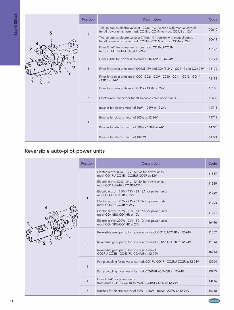
84
Position Description Code
1
Electric motor 80W - 12V - S1 9A for power units mod. CO1RU-CO1R - CO2RU-CO2R at 12V 11587
Electric motor 80W - 24V - S1 5A for power units mod. CO1RU-24V - CO2RU-24V 11589
Electric motor 125W - 12V - S1 13A for power units mod. CO3RU-CO3R at 12V 11292
Electric motor 125W - 24V - S1 7A for power units mod. CO3RU-CO3R at 24V 11293
Electric motor 150W - 12V - S1 16A for power units mod. CO4NRU-CO4NR at 12V 11291
Electric motor 200W - 24V - S2 10A for power units mod. CO4NRU-CO4NR at 24V 16446
2
Reversible gear pump for power units mod. CO1RU-CO1R at 12-24V 11307
Reversible gear pump for power units mod. CO2RU-CO2R at 12-24V 11314
Reversible gear pump for power units mod. CO3RU-CO3R - CO4NRU-CO4NR at 12-24V 16083
3
Pump coupling for power units mod. CO1RU-CO1R - CO2RU-CO2R at 12-24V 13204
Pump coupling for power units mod. CO4NRU-CO4NR at 12-24V 13205
4 Filter G1/4” for power units from mod. CO1RU-CO1R to mod. CO3RU-CO3R at 12-24V 13176
5 Brushes for electric motor of 80W - 125W - 150W - 200W at 12-24V 14718
Position Description Code
4
Two-solenoids electro valve at 12Vdc - “C” version with manual control for all power units from mod. CO1NU-CO1N to mod. CO4/5 at 12V 20610
Two-solenoids electro valve at 24Vdc - C” version with manual control for all power units from mod. CO1NU-CO1N to mod. CO16 at 24V 20611
5
Filter G1/4” for power units from mod. CO1NU-CO1N to mod. CO3NU-CO3N at 12-24V 13176
Filter G3/8” for power units mod. CO4-12V - CO4-24V 13177
Filter for power units mod. CO4/5-12V and CO4/5-24V - CO4-12 and CO4-24V 13179
Filter for power units mod. CO7- CO8 - CO9 - C010 - C011 - C013 - CO14 - C015 at 24V 13182
Filter for power units mod. CO12 - CO16 at 24V 13183
6 Electrovalve connector for all solenoid valve power units 12632
7
Brushes for electric motor of 80W - 125W at 12-24V 14718
Brushes for electric motor of 200W at 12-24V 14719
Brushes for electric motor of 300W - 550W at 24V 14720
Brushes for electric motor of 1000W 14721
Reversible auto-pilot power units
SPAR
E PA
RTS

85
Position Description Code
1
Electric motor 600W - S2 65A for power unit mod. CO500/3/0,5U-CO500/3/0,5 at 12V 11301
Electric motor 500W - S2 30A for power unit mod. CO500/3/0,5U-CO500/3/0,5 - CO500/4/0,75U-CO500/4/0,75 at 24V 11302
Electric motor 800W - S2 42A for power unit mod. CO500/6/0,75U-CO500/6/0,75 at 24V 11613
2
Gear pump for power unit mod. CO500/3/0,5U-CO500/3/0,5 at 12V - CO500/3/0,5U-CO500/3/0,5 at 24V 11664
Gear pump for power unit mod. CO500/4/0,75U-CO500/4/0,75 at 24V 11665
Gear pump for power unit mod. CO500/6/0,75U-CO500/6/0,75 at 24V 11666
3 Pump coupling for all CO500 power units 10486
4
Two-solenoids electrovalve at 12Vdc - C” version with manual control for power units mod. CO500/3/0,5U-CO500/3/0,5 at 12V 20610
Two-solenoids electrovalve at 24Vdc - C” version with manual control for power units mod. CO500/3/0,5U-CO500/3/0,5 - CO500/4/0,75U- CO500/4/0,75 - CO500/6/0,75U-CO500/6/0,75 at 24V
20611
5 Suction fi lter for all CO500 power units 13180
6 Filter for all CO500 power units 13182
7 Electrovalve connector for all solenoid valve power units 12632
8 Spacer for electric motor for all CO500 power units 12912
9 Brushes for electric motor of 500W - 600W at 12-24V 14720
Position Description Code
1
Electric motor 125W 12Vdc - S1 13A for power unit mod. CO3RAU-CO3RA at 12V 11292
Electric motor 125W 24Vdc - S1 7A for power unit mod. CO3RAU-CO3RA at 24V 11293
Electric motor 200W 12Vdc - S1 22A for power unit mod. CO4RAU-CO4RA at 12V 11294
Electric motor 200W 24Vdc - S1 10A for power unit mod. CO4RAU-CO4RA at 24V 11295
2Gear pump for power unit mod. CO3RAU-CO3RA at 12-24V 11321
Gear pump for power unit mod. CO4RAU-CO4RA at 12-24V 11328
3Pump coupling for power unit mod. CO3RAU-CO3RA at 12-24V 13201
Pump coupling for power unit mod. CO4RAU-CO4RA at 12-24V 10468
4
Two-solenoids electrovalve at 12Vdc - C” version with manual control for power units mod. CO3RAU-CO3RA - CO4RAU-CO4RA at 12V 20610
Two-solenoids electrovalve at 24Vdc - C” version with manual control for power units mod. CO3RAU-CO3RA - CO4RAU-CO4RA at 24V 20611
5 Filters for power units mod. CO3RAU-CO3RA-CO4RAU-CO4RA at 12-24V 13182
6 Electrovalve connector for all solenoid valve power units 12632
7Brushes for electric motor of 125W at 12-24V 14718
Brushes for electric motor of 200W at 12-24V 14719
Power-assisted electro-hydraulic power units
Solenoid valves auto-pilot power units with automatic filling
SPA
RE
PA
RTS

86
WARRANTY CONDITIONS
Twin Disc guarantees his equipment are sold and supplied against any faulty manufacturing or defects whether they are the result of the design, the raw material or construction under the terms and restrictions indicated below:1) Warranty validity period1.a. The period of warranty is twenty four (24) months starting from the date of the first use by the original consumer or thirty (30) months from the date of delivery of the products to the forwarder, distributor or wholesaler. In case our systems are mounted or used on work or commercial boats the guarantee period is of twelve (12) months from the date of production. The manufacturer has the right to require from the client proof of the commissioning date specified on the guarantee request. 1.b. This period is neither extended nor interrupted through legal or amicable claims on the part of the client. At the end of this period, the guarantee is terminated without further consideration.1.c. The warranty will not be renewed following repairs or replacement or if the item is resold.2) Conditions that make the warranty null and void2.a. The obligation of guarantee does not apply in case of negligence, faulty maintenance or supervision, operators responsibility, imprudence, non observance of recommended or operating instructions, incidents resulting from a cause of force majeure or the use of oil of insufficient quality for the equipment. The manufacturer is not responsible for any damage caused by loss of oil or leaks.2.b. The guarantee also does not apply for any incidents resulting from a cause of force major or Acts of God, as well as any damage, replacement or repairs exceeding the normal wear.2.c. The guarantee is not valid in case some of our components are installed on a control system together with other manufacturers’ products.2.d. The guarantee does not apply if the equipment is not returned to the manufacturer in the state in which it broke down or if it has previously been disassembled, repaired, modified either by a third party, the user or the client.2.e. The warranty does not cover failure due to construction or the choice of unsuitable materials whenever the customer has order the product with such characteristics in spite of prior advice given by Twin Disc.3) Conditions of call-out3.a. In case of equipment failure within its warranty period the manufacturer or service center, dealer and distributor, must be contacted to authorized any work. The client must do his best for the assistant to be able to ascertain these defects and to perform corrective actions. After receiving proper notification of the equipment defect, the assistance shall correct this fault as soon as possible, reserving the right, if applicable, to modify all or part of equipment in order to fulfil the obligations.3.b. The repair or replacement of the defective components under warranty condition is left to the technical staff judgement and the warranty is limited both to repair in the manufacturer’s shop or the nearest authorized service center, at its own cost within the shortest possible time of the equipment and parts supplied or to the article replacement, in case it is not reparable.
3.c. The defective products must be sent pre-paid togheter with a copy of invoice as well as the return form.3.d. Twin Disc or its assistance, agrees to repair the vessel in a good workmanlike manner. In case the repairing is not under warranty as specified in the condition paragraph 2, the owner agrees to pay Twin Disc for said work, labour and materials at Twin Disc usual and customary time and material charge unless specifics prices for specific items or job are agreed upon. Price quotes by personnel are rough estimates and are not binding upon, unless the quote is in writing and signed by the owner and/or representative.3.e. During the guarantee period, the cost of labour, dismantling and reassembly of the faulty items, repairing, travelling and accommodation expenses for technicians are the responsibility of Twin Disc. The shipping costs for repaired or replaced products, as well as for hauling or furniture dismantling shall be paid by the client.3.f. Emergencies: Twin Disc prefers to do work on vessels only with owner’s specific instruction. However Twin Disc does reserve the right to repair owner’s vessel if in the opinion of Twin Disc an emergency arises making such action necessary to protect the vessel. Owner agrees to pay for emergency hauling and/or necessary repairs at regular prevailing rates in case the job is not under warranty.3.g. Twin Disc reserves all rights against the vessel and personally against the owner for payment of all charges in full.3.h. Twin Disc shall not be responsible for any damage to said vessel while accessed by Twin Disc nor shall Twin Disc be responsible for damage to or loss of any items or personal property, gear or any other appurtenances left aboard the vessel, whether vessel’s owner, representative and agents have at all time access to the vessel and, accordingly, Twin Disc does not have exclusive custody, care and control of the boat. 3.i. Twin Disc does not provide insurance for vessels; Twin Disc insurance liability coverage for Twin Disc only. Owner agree that he will provide his own insurance for his vessel, will keep coverage in effect for the time period the vessel being accessed by or in custody of Twin Disc and release Twin Disc from any damage.4) General warranty terms4.a. The obligation of the guarantee only applies if the defect appeared under normal operating conditions stipulated for this type of supply or indicated by the manufacturer in writing.4.b.The components replaced under warranty must return immediately to Twin Disc as they are no longer customer’s property.4.c. Twin Disc reserves the right to change its models or parts of them without any obligation to make the same alterations to any products previously manufactured.4.d. The client agrees that the manufacturer will not be responsible for damage resulting form the client non compliance with any of the obligations defined above.4.e. No claim may be made for compensation such as personal injury, damage to goods other than those concerned in this document, privation of possession, operating losses, commercial damage or loss of earnings.
Printed by Nova Arti Grafi che - Signa (FI) - Italia
All rights reserved.Copywright © Twin Disc S.r.l. - Limite sull’Arno
Revision 6, printed on September 2010

TM 1
International Distributors NetworkNORTH AMERICAU.S.A.Twin Disc South East Inc.11700 N.W. 101st Road, Suite 19 Medley, FL 33178Ph: +1 (305) 885.07.07 Fax: +1 (305) [email protected] AMERICAARGENTINATurbodiesel S.A.Osvaldo Cruz 1910 Capital Federal1293 Buenos Aires Ph/Fax: +54 (114) [email protected] www.turbodiesel.com.arBRASILMarine Express Com. Imp. Exp. Ltda.Rod. BR 101 Km164, 90 Centro88200-000 Tijucas - SC Ph: +55 (11) 503.571.65 Fax: +55 (11) [email protected] Belmar IngenieriaAinavillo 633 - 4070544 Concepciòn Ph: +56 (41) 46.55.32 - Fax: +56 (41) [email protected] - www.belmar.clEUROPEDENMARKFred Rasmussen - Odense APSOve Gjeddes Vej 23 - DK5220 OdensePh: +45 (65) 56.05.60 - Fax: +45 (65) [email protected] www.fred-rasmussen.dkFINLAND Meredin - Ulkoiluaitta OYPuolalankatu 6 - 20100 Turku Ph: +358 (2) 27.52.75 - Fax: +358 (2) [email protected] - www.meredin.fi FRANCE Esco Transmissions S.A.34, Rue de la ferme St Ladre - BP 4002395471 FossesPh: +33 (0) 134 31.95.95 Fax: +33 (0) 134 31.95.99 [email protected]
GREECE Internaftiki A.E.B.E. 6, Alipedou str. - GR 18531 PiraeusPh: +30 (210) 412.69.97 Fax: +30 (210) [email protected] Italia S.r.l.Via Salani, 1 - 50050 Limite S/A - FirenzePh: +39 (0) 571 97.91.1 Fax: +39 (0) 571 [email protected] BV Krommewetering 61A - Utrecht 3543 AMPh: +31 (0) 30 24.08.040 Fax: +31 (0) 30 [email protected] - www.belship.nlPOLAND Taurus Sea Power Ltd.Ul. Dzwigowa 13A - 80-414 Gdansk Ph: +48 (58) 34.43.050 Fax: +48 (58) [email protected] www.taurus.gda.plPORTUGAL Nautiradar Lda. Rua Antònio Saldanha, 65 1400-020 LisboaPh: +351 (21) 300.50.50 Fax: +351 (21) [email protected] www.nautiradar.ptSPAIN Ecamar Propulsores Marinos S.L.Juan de La Cierva, 15 - Local 1708339 Vilassar de Dalt - BarcelonaPh: +34 (93) 55.552.30 Fax: +34 (93) [email protected] Mitab Marin Industriteknik ABBox 1073 - 475 22 Ockero Ph: +46 (31) [email protected] www.mitabmarin.se
UNITED KINGDOMMarine & Industrial Transmissions Ltd.South Street - QueenboroughKENT ME 11 5EE - GBPh: +44 (0) 1795 58.08.08 Fax: +44 (0) 1795 [email protected] - www.mitgroup.co.uk MEDITERRANEAN-BASINEGYPTDolphin Marine Co.66, El Taweniate, Smouha - AlexandriaPh/Fax: +20 (34) 25.21.79 Mob: +20 (12) [email protected] MALTGeneral Automation Services Ltd. 13 - 15, Telleritu Street Ghaxaq GXQ 1333 Mob: +356 99 [email protected] TURKEY Nautique Denizcilik Otomotiv San. ve Tic. Ltd. Sti.Sahil yolu cad. Inci Sk.Efe Emir Is Mrk. No:1/1-3 Guzelyali34903 Pendik - IstanbulPh: +90 (216) 494.65.60Fax: +90 (216) 494.65.04erol.degerli@nautiqueproducts.comwww.nautiqueproducts.comOCEANIA AUSTRALIA Twin Disc Pacifi c Pty Ltd.40 Telford Street - BrisbaneVirginia, Queensland 4014Ph: +61 (07) 326.512.00 Fax: +61 (07) [email protected] ASIA SINGAPORE Twin Disc (Far East) Pte Ltd.10 Fifth Lok Yang RoadSingapore 629761Ph: +65 (62) 67.08.00 Fax: +65 (62) [email protected]

Twin Disc S.r.l. - Via E. e P. Salani, 1 - 50050 Limite Sull’Arno (Fi) Italy Ph. +39 0571 97911 - Fax +39 0571 979143 - [email protected]
www.bcsmarine.com - www.twindisc.com